INSTRUCTIONS BOTTLE FILLER WITHOUT PUMP
|
|
|
- Rodger Chandler
- 5 years ago
- Views:
Transcription
1 INSTRUCTIONS BOTTLE FILLER WITHOUT PUMP CHAPTER 1: DESCRIPTION OF THE MACHINE We thank you for choosing our linear gravity FILLER series RIM. IF YOU FOLLOW THESE INSTRUCTIONS CAREFULLY, PAYING FULL ATTENTION TO ALL PARTS OF THE INSTRUCTIONS, this device will permit you to bottle all so-called flat, i.e., non-carbonated, liquids, of densities comparable to sweet liqueurs, disposing of liquids specified as follows, placed on a height slightly higher than the float chamber, ON A CONSTANT LEVEL. OTA CHAPTER 2 GENERAL SAFETY WARNINGS Before putting the device into functioning, the user should know how to carry out all the operations described in the present manual, skilfully and with complete safety. CHAPTER 3: INTENDED AND UNINTENDED USES MATERIALS DEVICE RESTRICTED TO USE BY ONE SINGLE OPERATOR KEEP OUT OF REACH OF CHILDREN. 3.1 Designed for gravity filling, ON A CONSTANT LEVEL, of bottles and flasks (hereinafter referred to as BT/FL) with ROUND GLASS MOUTHS. Other materials, for example, PET and plastic materials in general, can only be bottled after inspection and experimentation with the recipient provided by the client. 3.2 REFILLABLE LIQUIDS IN THE STANDARD VERSION: all liquids compatible with stainless steel AISI 304 (18/10) may be filled using the float chamber and distributors the chromed brass of the a and fittings, the moplen with brass insert on the mechanical float 68b, the noryl of the internal part of the e.p. Using standard equipment, it may fill: WATER, PERFUMES, HAIR LOTIONS, ANTI-CRYPTOGRAM products, PETROLEUM DERIVATIVES. 3.3 FILLABLE LIQUIDS WITH THE FOODSTUFF VERSION (see TECHNICAL TABLE): WINES-DRY VINEGARS BEERS-SWEET AND DRY LIQUEURS-OILS, SEMI-GRAPE and FRUIT JUICES 3.4 OTHER LIQUIDS NOT MENTIONED MAY ALSO BE FILLED UPON REQUEST AND WITH OUR WRITTEN AUTHORISATION. EXTREME WORKING TEMPERATURES C. DO NOT USE THIS DEVICE TO FILL OR TRANSFER FLAMMABLE LIQUIDS. DO NOT USE THIS MACHINE IN AN EXPLOSIVE ENVIRONMENT. DO NOT USE THIS MACHINE TO FILL OR TRANSFER LIQUIDS WHICH ARE HAZARDOUS BY CONTACT OR INHALATION.
2 CHAPTER 4: MOVEMENT AND DISASSEMBLY The standard version device is delivered protected by a plastic sack, wrapped in an undulated cardboard box, completely sealed with a plastic safety strap. CHECK THE INTEGRITY OF THE PACKING IMMEDIATELY UPON DELIVERY. IF THE PACKING IS DAMAGED, THIS MUST BE REPORTED TO THE SHIPPER WITH AN ANNOTATION ON THE DOCUMENT ACCOMPANYING THE MACHINE. THE BUILDER WILL NOT BE HELD LIABLE FOR DAMAGE CAUSED IN TRANSPORT. Check (see TAB. i) the presence of the EQUIPMENT PARTS inside the wrapping. The limited weight permits easy movement of the device with an ordinary two-wheeled forklift to the intended area of use. FOLLOW THE INSTRUCTIONS. HIGHLY FRAGILE. DO NOT TIP CONTROL THE CORRESPONDENCE BETWEEN OF THE PARTICULAR PARTS LISTED IN TECHNICAL TABLE WITH THE CONTENTS OF THE BAG NORMALLY FOUND INSIDE THE FLOAT CHAMBER 68 ALL PACKAGING WASTE MATERIAL SHOULD BE REMOVED AND DISPOSED OF IMMEDIATELY USING NORMAL WASTE DISPOSAL METHODS. CHAPTER 5: Choice of the WORKSITE BOTTLES TRIMMINGS 5.1 The working area of the machine should be in compliance with all legislation governing the product involved. In particular, check to ensure that the support surface beneath the feet of the device is level. The environment must be well lit, and the working environment to the front and both sides must be left completely unencumbered for a radius of at least 1.5 metres. It should be noted that the device, when functioning, must be constantly supplied with empty bottles (production of approximately 130 litres hour/distributor). To work comfortably and in safety, we recommend that you arrange an adequate quantity of empty BT/FL upstream from the device, with a broad plane surface support table downstream, so as to avoid long and/or or continual displacements, or that you use a conveyor belt to transfer the BT/FL to the area for corking: 5.2 BOTTLES AND RECIPIENTS TO BE FILLED The recipients should be connected to round-shaped filling mouths without defects and/or cracks, simultaneously permit the passage of a minimum of air. For dimensions, see bottle technical table. The BT/FL to be filled should be sub-divided by height. It is not possible to fill BT/FL of different height simultaneously. 5.3 TRIMMING To avoid accidental bottle breakage, the operator trimming must include: gloves, heavy long apron, footwear with anti-slip soles. NOTA CHAPTER 6: GENERAL STANDARDS OF IMPLEMENTATION 6.1 Hydraulic connection: connect the device to a tube which can also be supplied by ourselves at request, diameter 15-16mm, if standard, or mm 19 if with stainless steel taps and fittings, attach with clips to the pipe union hose fitting supplied. Use flexible tubes of a plastic or metallic spiral type, maximum tube length: recommended 5 metres.
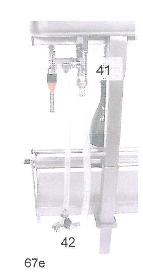
3 6.2 BT/FL filling level regulation see figs. 3a-b-c-d-e-f- 6.4a Loosen the two wing nuts pos 67c to release the rear support, remove it by lowering it from the BT/FL the float chamber drop stop group pos 63. Position any distributor in a vertical position. 6.4b Take a BT/FL to be filled and support it at the sealing cone fig3a, do not press upwards. The measure, L fig3a A or L1 fig3a B, will correspond to the filling level of the BT/FL 6.4f Pull the cone 60 downwards if it desired to fill the bottle more. 6.4g Pull the cone 60 upwards if it is desired to fill the bottle less. 6.4h To prevent the flow upwards of cone 60, combine the filling of the grey space with the thickness of cut rubber (supplied) pos , respectively by , mm. 6.4i Pull the B/F upwards approximately 20mm, until it completely exposes the two BT/FL liquid entry and air outlet holes during filling. 6.4l Close in this position and simultaneously pull the drop stop group upwards, fig.3b CD until the lower support tube 67b touches the bottle. 6.4m Allow the drop stop group automatically to block the flow downwards by means of the blocking lever 67d. 6.4n Position the bottle and distributor vertically, support the rear support bar pos 67a on the bottle, check that it is parallel to the fixed bar, and pull the wing lock screws 67c. 6.4o Proceed to equip the rest of the distributors with the same thicknesses of the first distributor prepared. NOTA NOTA CHAPTER 7 FUNCTIONING 7.1 FILLER FUNCTION (standard version see Figs b). For liquids ready for filling, or already pre-filtered. 7.1a Open the liquid intake, tap pos 41f, originating from the storage container, the liquid begins to exit into the float chamber pos 68, wait a few moments until the level in the float chamber reaches 100mm (the sphere of the float must not be closed). 7.1b Insert the empty bottles into the distributors (levels previously established 6.4). 7.1c Remove the full bottles. 7.1d Any possible drops of liquid which may flow down from the outside of the distributors in a closed position, are gathered in the drop stop float chamber 67 of the latter, through the tube pos 67e and conveyed into the empty bottle previously placed for the purpose. 7.1n The procedure described above permits the user to leave the machine unattended with complete safety, with the liquid enclosed in the float chamber, for the time strictly necessary to solve minor problems, for example: renewing the empty bottle supply, moving tubes from empty recipients to full ones, making phone calls. NEVER LEAVE THE DEVICE UNATTENDED WITH THE INLET TAP pos 41f OPEN IF PARTICULARLY LONG ABSENCES FROM THE FILLING ROOM ARE ANTICIPATED. TURN OFF THE TAP. CHAPTER 8 CLEANING AND MAINTENANCE OF THE DEVICE 8.1 PREVENTIVE CLEANING (new machine). Prearrange a quantity of approximately litres of hot water 60/80 C with non-foaming dish-washing detergent or other detergent for kitchen hygiene (such as Detersol or Sanaton). Operate the device as described under 9, with the float chamber pos 68 full of detergent water, continue to insert and remove the empty bottles at all distributors until the float chamber is empty. Rinse abundantly with hot water. Allow to dry in open air. Option upon request: for perfect rinsing and drying of the internal conduits of the distributor we advise closing the open distributor locking flasks afterwards (see fig 2b art.56232) The device with the distributor lock flasks assembled can be subjected to flowing steam sterilization treatment at 120 C.
4 8.2 DAILY CLEANING Every time you finish the day s work, especially if you are working with edible liquids, it is indispensable to proceed with careful cleaning of the tubes, the tub and distributors (see 8.1). 8.3 EXTRAORDINARY MAINTENANCE AND CLEANING OF DISTRIBUTORS: 8.3a Unscrew the ring nut 58 Fig9 8.3b Immerse the entire device in detergent solution pushing the sliding tube upwards 51 (we advise closing the locking flask art.56232) afterwards, and moving the device energetically). 8.3c Allow the device to sit for a while to facilitate removal of any incrustation. 8.3d Rinse abundantly in water. Let dry. Reassemble entire unit. 8.4 DISTRIBUTOR DISASSEMBLY DUE TO LOSS OF LIQUID Procedure to be followed to substitute parts which may become damaged through wear and tear. See fig 9 8.4a Leave the distributor assembled on the float chamber pos b Push the sliding tube upwards pos c Using a small screwdriver remove the peak O-ring pos d Withdraw the sliding tube 51+ lip packing seal 52)+washer 53 +spring e REPLACEMENT OF LIP PACKING SEAL (hereinafter referred to as LIP PACKING) NOTE: Every time you disassemble the sliding tube 51 until it withdraws the LIP PACKING it becomes necessary to replace the LIP PACKING52 as well, since the lower internal sealing lip in the disassembly phase is easily damaged beyond repair. Lubricate the new LIP PACKING 54 using oil or Vaseline. Also lubricate [CHECK] the tube 56. The LIP PACKING 52 should be inserted beforehand, with the sealing lips turned downwards, in the suitable seat based in the tube 51. Using a small screwdriver or knife, facilitate the insertion, NOTE: TAKE CARE TO AVOID DAMAGING the sealing lips on the LIP PACKING. Take in hand the sliding tube 51 with the LIP PACKING 52 inserted. Insert the entire unit into the tube 56, rotating slowly in one direction, and pushing only forwards, slowly, until it completely passes the liquid entry holes. Continue to push upwards slowly, until you uncover the cutting seat on the O-ring 59. Place the O-ring f Reassemble the spring 54 and the washer g REPLACEMENT OF O-ring 59 Push the sliding tube upwards into pos 51. Release the cutting seat of the O-ring59. withdraw the damaged O-ring using a small screwdriver or knife. Do NOT allow the sliding tube 51 to slide downwards, since it could cause it to escape from its own seat on the LIP PACKING 52, with consequent repetition of the above, at 8.4e. Using simple pressure, install the new O-ring DISASSEMBLY FOR CLEANING OF THE FLOAT AND SEALING BALL Remove the lid 68a, unscrew the two split pins pos 68c, using a wrench, unscrew 14mm pos 68e unscrew pos 68d. To remove incrustations, use appropriate chemical products. DO NOT USE ABRASIVES OR SHARP METAL DEVICES to clean the sealing ball and the support seat. Pos 6 6b Denomination 68b Stainless steel ball float with spindle 68c n.2 Split pins mm2x16 68d Spindle with stainless steel ball 68e Guide nut spindle hole6 68f Connection total discharge 68g Lock nut ball mount
5 CHAPTER 9 TROUBLE SHOOTING REFILL THE PUMP BODY WITH LIQUID BEFORE STARTING THE MOTOR Refiller with distributors Nr PROBLEM REASON FOR DAMAGE SOLUTION The liquid enters from a height exceeding 10 metres. Crust or impediments to the closing of the liquid intake ball 7 The float 68b does not close the maximum level of liquid entering the float chamber 68 8 The float 68b does not close the level between the float chamber 68 9 The float 68b does not close the fill level in the float chamber 68 The liquid enters from the pump under too much pressure. Failure of hand wheel 45 to open on the by-pass on the suction pump. Encrusted Ball and/or sealing seat. Presence of foreign bodies in the closing area of the ball 10 The fill level of the bottles is not constant. Bottles of various heights 11 Failure to stop fill level with escape of air and liquid between the sealing cone and the neck of the recipient to be filled 12 Loss of liquid between sliding tube 51 and washer 53 dripping between tube 51 and O-ring pos 59 Mouth of recipient not round, has cutting edges or slight cracks Sealing cone pos 60 worn spring 54 worn or broken Loss of lip packing seal pos 52 Loss from O-ring pos 59 Lower the level to 10 metres Disassemble float 8.6 Eliminate the impediment. Lower the range of the pump closing the valve placed on the delivery or open the pump bypass v.5.3b Disassemble 68d spindle with ball. 8.6 Clean ball control and clean ledge area. Select the bottles to be filled based on heights Eliminate the defective containers 4.2 Replace sealing cone Replace spring pos Replace trimming pos g Replace or pos e

6 CHAPTER 10 FIGURES

7

8

9


10
INTRODUCING SCHEDULE. Lawful owner Stefano Gollini. The paragraphs preceded by this symbol, if not respected can lead to damages to the machine
 RIBAGAS Page. 2 of 5 ART. 1 0 7 0 RIBAGAS 4 INTRODUCING SCHEDULE REGISTER N YEAR STATEMENT OF CONFORMITY UR Chill Tech. srl DECLARE UNDER ITS OWN RESPONSIBILITY THAT THE ABOVE MENTIONED MACHINE SUITS THE
12S 1st Stage. -Maintenance Procedure-
 12S 1st Stage -Maintenance Procedure- 1 Warning! All maintenance and repair procedures MUST be performed by a Mares authorized Service Center and/or Distributor. Therefore, the information provided below
Poollift Delphin. Version: February, 2015 MANUAL AND OPERATING INSTRUCTIONS
 Poollift Delphin Version: February, 2015 MANUAL AND OPERATING INSTRUCTIONS Content 1. Introduction... 3 2. Technical Specifications... 3 Used materials... 3 3. Installation Instructions... 4 Fastening
Operation Manual. PEGAS NovoTap, PEGAS NovoTap+
 Operation Manual PEGAS NovoTap, PEGAS NovoTap+ www.beerinnovations.com Operation Manual 3 1. Assembling Diagram PEGAS NovoTap Assembling Diagram 1. Body 2. Front part of the body 3. Front part of the body
WHEATLEY WHEATLEY SERIES 500 SWING CHECK VALVE. Installation, Operation and Maintenance Manual
 WHEATLEY SERIES 500 SWING CHECK VALVE STANDARD INTEGRAL SEAT & OPTIONAL REMOVABLE SEAT 2" FP - 6" FP 150# - 1500# 8" FP - 12" FP 150# - 900# API 6D and B16.34 2" FP - 4" FP 5000# DRILLING PRODUCTION VALVE
MAINTENANCE PROCEDURE FOR X 650
 MAINTENANCE PROCEDURE FOR X 650 X 650 25. juli 2005-1/6 MAINTENANCE PROCEDURE FOR X 650 2 ND STAGE WARNING: This maintenance procedure is only for appointed Scubapro technicians that completed a course
DISASSEMBLY AND ASSEMBLY INSTRUCTIONS FOR LIQUID RING COMPRESSORS
 DISASSEMBLY AND ASSEMBLY INSTRUCTIONS FOR LIQUID RING COMPRESSORS SA INTRODUCTION These instructions are for the maintenance personnel for maintenance and repair of compressors series SA. Disassembly and
RG1200 Service and Repair Manual
 Dive Rite RG 1200 Regulator Service and Repair Manual Page 1 Text and Photography by Pete Nawrocky Copyright ( ) 1999-2000, Lamartek, Inc., dba Dive Rite RG1200 Service and Repair Manual First Stage.........................................
THE HF-300 SERIES. Operating and Service Manual. Series includes all variants of HF-300/301
 THE HF-300 SERIES Operating and Service Manual Series includes all variants of HF-300/301 Issue A July 2015 1 TABLE OF CONTENTS 1. Description... 3 2. Installation... 3 3. Operation... 4 3.1. Spring Loaded...
ATD LB PRESSURE BLASTER INSTRUCTION MANUAL
 ATD-8402 90LB PRESSURE BLASTER INSTRUCTION MANUAL SAVE THESE INSTRUCTIONS SAFETY INSTRUCTIONS FOR SANDBLASTER 1. Before opening the tank release the air pressure on the sand tank. To do this, turn off
Needle valve. Contents. User s Manual. (1) Be sure to read the following warranty clauses of our product 1. (2) General operating instructions 2
 Be sure to read the following warranty clauses of our product 1. (2) General operating instructions 2") Serial No. H-V024-E-7 Needle valve User s Manual Contents (1) Be sure to read the following warranty clauses of our product 1 (2) General operating instructions 2 (3) General instructions for transportation,
Serial No. H-V024-E-7 Needle valve User s Manual Contents (1) Be sure to read the following warranty clauses of our product 1 (2) General operating instructions 2 (3) General instructions for transportation,
Assembly-, installation- and maintenance instruction manual for bladder accumulators IBV / EBV , top reparable
 Page 1 von 8 Assembly-, installation- and maintenance instruction manual for bladder accumulators IBV / EBV 100-575, top reparable Content Seite 0 Legend 2 1 Overview 2 2 Accumulator assembly and installation
Pectoral Machine. User manual E S S E N T I A L S T R E N G T H
 E L E M E N T and the cable E S S E N T I A L S T R E N G T H User manual 1 and the cable and The identification plate of and manufacturer, affixed on the back panel of the weight stack, gives the following
BioAerosol Nebulizing Generator. Operation and Maintenance User Manual
 BioAerosol Nebulizing Generator Operation and Maintenance User Manual INTRODUCTION The BANG or BioAerosol Nebulizing Generator is a unique nebulizer for the generation of aqueous aerosols at a low air
Pure Water Power Purification System 4-Stage RODI Operations Manual
 Pure Water Power Purification System 4-Stage RODI Operations Manual Flush Valve Lever Quick Disconnect for RO Water Testing Water Supply In Drain Hose Pure Water Out to Waterfed Pole New Machine Setup
Combination Air Valve
 Combination Air Valve For Sewage and Wastewater Model C50 Installation, Operation and Maintenance Manual (IOM) Table of Contents General... Page 2 Safety... Page 2 Operational Data... Page 3 Materials
Regulators repair and maintenance. XS Compact 2nd stage. January 2014 Rev XSC /3 Ed. C /14 1
 XS Compact 2nd stage January 2014 Rev XSC /3 Ed. C /14 1 XS Compact 2nd stage WARNING! This manual is intended for use by expert technicians who have already received training in equipment repairs and
KTM OM-2 SPLIT BODY FLOATING BALL VALVES INSTALLATION AND MAINTENANCE INSTRUCTIONS
 Before installation these instructions must be fully read and understood SECTION 1 - STORAGE 1.1 Preparation and preservation for storage All valves should be properly packed in order to protect the parts
User's Manual. MixRite TF 10. Edition 05.08
 User's Manual MixRite TF 10 Edition 05.08 1 Tefen MixRite TF 10 fertilizer and chemicals Injector Congratulations on your purchase of one of Tefen s high quality products. To get the best results from
IMPORTANT PLEASE READ BEFORE COMMENCING INSTALLATION
 IMPORTANT PLEASE READ BEFORE COMMENCING INSTALLATION This Fitting Guide is designed to assist in the Installation of your Reverse Osmosis System. Some of the parts that are supplied with each system may
Standard Operating and Maintenance Instructions for Pumping System Model PS-90
 Standard Operating and Maintenance Instructions for Pumping System Model PS-90 High Pressure Equipment Company 2955 West 17th Street, Suite 6 PO Box 8248 Erie, PA 16505 USA 814-838-2028 (phone) 814-838-6075
Code AWC20HP Air Compressor
 Code 951816 AWC20HP Air Compressor Index of Contents Index of Contents 02 Declaration of Conformity 02 What s Included 03 Safety Precautions 03 Specifications (AWC20HP Air Compressor) 04 Assembly Instructions
Wafer Check Valve. Contents. User s Manual. (1) Be sure to read the following description of our product warranty 1
 Be sure to read the following description of our product warranty 1") Serial No. H-V066-E-3 Wafer Check Valve User s Manual Contents (1) Be sure to read the following description of our product warranty 1 (2) General operating instructions 2 (3) General instructions for
Serial No. H-V066-E-3 Wafer Check Valve User s Manual Contents (1) Be sure to read the following description of our product warranty 1 (2) General operating instructions 2 (3) General instructions for
Hydraulic Punch Drivers
 SERVICE MANUAL 7804SB / 7806SB Quick Draw 7704SB / 7706SB Quick Draw Flex Quick Draw Hydraulic Punch Drivers Serial Codes AHJ and YZ Read and understand all of the instructions and safety information in
PENBERTHY SUBMERSIBLE AUTOMATIC SUMP DRAINER INSTALLATION, OPERATION AND MAINTENANCE INSTRUCTIONS
 Before installation, these instructions must be read carefully and understood. PRODUCT WARRANTY Emerson warrants its Penberthy products as designed and manufactured to be free of defects in the material
THE MF-400 SERIES. Operating and Service Manual. Series includes all variants of MF-400/401
 THE MF-400 SERIES Operating and Service Manual Series includes all variants of MF-400/401 Issue A October 2013 1 TABLE OF CONTENTS 1. Description... 3 2. Installation... 3 3. Operation... 4 4. Special
MUD 1. Vent check valves. Instruction and maintenance manual.
 MUD 1 Vent check valves Instruction and maintenance manual. Version: 04-02-2011. 2 List of Contents 1. INTRODUCTION 3 1.1 The Problem... 3 1.2 The Solution... 3 2. RULES AND REGULATIONS 3 2.1 General requirements....
WHEATLEY Series 500 Swing Check Valve
 Document Number: TC003001-13 Revision: 02 WHEATLEY Series 500 Swing Check Valve Installation, Operation, and Maintenance Manual TABLE OF CONTENTS BILL OF MATERIALS...3 SCOPE...5 INSTALLATION AND OPERATION
Operating instructions - Translation of the original -
 Operating instructions - Translation of the original - 6001-6010 Sample valve KIESELMANN GmbH Paul-Kieselmann-Str.4-10 D - 75438 Knittlingen +49 (0) 7043 371-0 Fax: +49 (0) 7043 371-125 www.kieselmann.de
Assembly Drawing: W-311B-A01, or as applicable Parts List: W-311B-A01-1, or as applicable Special Tools: , , &
 REDQ Regulators Model 411B Barstock Design Powreactor Dome Regulator OPERATION AND MAINTENANCE Contents Scope..............................1 Installation..........................1 General Description....................1
THE BP-301 SERIES. Operating and Service Manual. Series includes all variants of BP-301 (LF 0.1Cv / MF 0.5Cv)
") THE BP-301 SERIES Operating and Service Manual Series includes all variants of BP-301 (LF 0.1Cv / MF 0.5Cv) Issue B October 2015 1 TABLE OF CONTENTS 1. Description... 3 2. Installation... 3 3. Operation...
THE BP-301 SERIES Operating and Service Manual Series includes all variants of BP-301 (LF 0.1Cv / MF 0.5Cv) Issue B October 2015 1 TABLE OF CONTENTS 1. Description... 3 2. Installation... 3 3. Operation...
PRO SINK -R 1 and 2. Dilution system CONTENTS
 PRO SINK -R 1 and 2 Dilution system CONTENTS 1.0 Product description 2 2.0 Warnings.. 3 3.0 Installation procedure 4 4.0 Plumbing connections 4 5.0 Technical features.. 5 6.0 Maintenance... 6 7.0 Troubleshooting......6
Operation and Maintenance Instructions
 Hydratight Limited Bentley Road South Darlaston West Midlands WS10 8LQ United Kingdom Tel: +44 121 50 50 600 Fax: +44 121 50 50 800 E-mail: enquiry@hydratight.com Website: www.hydratight.com TOP COLLAR
POOL ROVER ST POOL CLEANER Installation Instructions
 POOL ROVER ST POOL CLEANER Installation Instructions A. ASSEMBLY FIG 1 - Place the seal over the top of the pool cleaner body and slide it down to the mouth. FIG 2 - Secure the seal beneath the flange
Booster Pump PB4-60 Replacement Kits
 Booster Pump PB4-60 Replacement Kits FOR YOUR SAFETY - This product must be installed and serviced by a contractor who is licensed and qualified in pool equipment by the jurisdiction in which the product
Pipettor. User Manual
 Pipettor User Manual Product Code Description Single Chanel Pipettor Variable 550.002.055 Volume 0.5 to 10ul 550.002.060 2 to 20ul 550.002.065 10 to 100ul 550.002.070 20 to 200ul 550.002.075 100 to 100ul
Right-Angle Tube Roller Model
 SPECIFICATIONS Model no. Free Speed (RPM) Throttle Rotation Max. Torque Ft-Lb Air Pressure psi Air Inlet Hose Air Flow @Free Speed Spindle Weight 909-1700 95 Lever type Reversible 240 90 1/2 NPT 1/2 I.D.
Filling valves AL, ALM Series Automatic filling units ALOMDIW, ALOMDNW Series
 Filling valves AL, ALM Series Automatic filling units ALOMDIW, ALOMDNW Series Main features Designed for automatic filling of sealed heating systems and for protection of the water mains from risk of contamination.
Car Baby Walker 2-in-1 Baby walker
 Car Baby Walker 2-in-1 Baby walker INSTRUCTIONS: Read the instructions carefully before use and keep them for future reference. The child may be hurt if you do not follow these instructions. EN 1273:2005.
BOSS PULISCI PROVA IMPIANTI MEDIA
 BOSS PULISCI PROVA IMPIANTI MEDIA Pump for power flushing operations and removal of impurities, suitable for hydraulic, solar, floor systems and for cooling circuits of medium size. Suitable for buildings,
DIRECT DRIVE DIXIE DOUBLE SEAMER Model 25D
 OPERATOR'S MANUAL DIRECT DRIVE DIXIE DOUBLE SEAMER Model 25D LUBRICATE DAILY: A. Gears inside gear housing at chuck shaft (1) Oil B. Seam rolls and cam rolls (4) - Oil C. Seam roll levers through gear
RARS5000 AIR BODY SAW OWNER S OPERATING MANUAL
 RARS5000 AIR BODY SAW OWNER S OPERATING MANUAL DESCRIPTION 1. No mar 2. No mar tip 3. Housing grip 4. Trigger 5. Air inlet 6. Air inlet plug 7. Plastic board Important! It is essential that you read the
RayPette Plus Autoclavable Pipette. User Manual
 RayPette Plus Autoclavable Pipette User Manual CONTENTS 1. YOUR NEW PIPETTE... 1 1.1. Adjustable volume pipettes... 1 1.3 Fully autoclavable... 2 2. UNPACKING... 3 3. INSTALLING THE PIPETTE HOLDER... 4
Procedure 85 Attaching The Humidifier To The Oxygen Flow Meter Or Regulator. Procedure 86 Administering Oxygen Through A Nasal Cannula
 Chapter 12 Respiratory Procedures Procedure 81 Checking Capillary Refill Procedure 82 Using A Pulse Oximeter Procedure 83 Preparing Wall-Outlet Oxygen Procedure 84 Preparing The Oxygen Cylinder Procedure
Pressure Dump Valve Service Kit for Series 3000 Units
 Instruction Sheet Pressure Dump Valve Service Kit for Series 000 Units. Overview The Nordson pressure dump valve is used to relieve hydraulic pressure instantly in Series 00, 400, 500, and 700 applicator
BRAKE WINCH RUP 503-[T/BT] EQUIPMENT FOR LIFTING LOADS. AT 053-[T/BT] xx
![BRAKE WINCH RUP 503-[T/BT] EQUIPMENT FOR LIFTING LOADS. AT 053-[T/BT] xx](/thumbs/88/115945274.jpg "BRAKE WINCH RUP 503-[T/BT] EQUIPMENT FOR LIFTING LOADS. AT 053-[T/BT] xx") Reference number: BRAKE WINCH RUP 503-[T/BT] EQUIPMENT FOR LIFTING LOADS DESIGNATED USE The brake winch RUP 503-[...]T series is a load lifting / lowering device. Device is equipped with safety brake for
Reference number: BRAKE WINCH RUP 503-[T/BT] EQUIPMENT FOR LIFTING LOADS DESIGNATED USE The brake winch RUP 503-[...]T series is a load lifting / lowering device. Device is equipped with safety brake for
Service and Repair Operative Manual MC9 1 st STAGE. MC9 1 st Stage. 1 st STAGE MC9. Jannuary Rev. MC9 /B Ed. C/13
 MC9 1 st Stage 137 1 st STAGE MC9 Jannuary 2009 - Rev. MC9 /B Ed. C/13 138 WARNING! This manual is intended for use by expert technicians who should attend or have already received training in equipment
Assembling & Installing your Pool Cleaner
 Assembling & Installing your Pool Cleaner STEP 1: Check Contents of the Box Remove the Badu Clean Supreme body and all parts from the box and check that the following components are included. Refer to
Santa Fe Cycles Assembly Guide Introduction
 Santa Fe Cycles Assembly Guide Introduction Congratulations on your purchase of your new Santa Fe bicycle. You have purchased a bicycle that has many features and qualities. Please take a few minutes and
INSTRUCTION MANUAL. Slavia 630/631
 INSTRUCTION MANUAL Slavia 630/631 Before handling the air rifle read this manual carefully and observe the following safety instructions. Improper and careless handling of the air rifle could result in
AIR/OVER HYDRAULIC JACK 20 TON
 AIR/OVER HYDRAULIC JACK 0 TON 4487 ASSEMBLY AND OPERATING INSTRUCTIONS 349 Mission Oaks Blvd., Camarillo, CA 930 Visit our Web site at http://www.harborfreight.com Copyright 999 by Harbor Freight Tools.
MODEL 200 KNIFE GATE VALVES INSTALLATION & MAINTENANCE MANUAL
 MODEL 200 KNIFE GATE VALVES INSTALLATION & MAINTENANCE MANUAL Index 1. List of components / General arrangement 2. Description 3. Handling 4. Installation 5. Actuators / Operation 6. Maintenance a. Changing
Engineering Data Sheet
 Page 1 of 6 CE MARKING AND THE PRESSURE EQUIPMENT DIRECTIVE 97/23/EC Valves must be installed into a well designed system and it is recommended that the system be inspected in accordance with the appropriate
RB70 Automatic Diluent Valve Maintenance Manual. Version 1.1 November 2006 Written by Tino de Rijk. Page 1 of 23
 RB70 Automatic Diluent Valve Maintenance Manual Version 1.1 November 2006 Written by Tino de Rijk Page 1 of 23 Table of Contents 1. Introduction... 3 2. ADV diagram and parts list (Pre June 2006)... 4
3/8" Dr. Air Butterfly Impact Wrench
 8192106 3/8" Dr. Air Butterfly Impact Wrench Owner s Manual Read and understand all instructions before use. Retain this manual for future reference. Specifications Construction: Polished aluminum and
Yoke Block Instruction Manual
 Yoke Block Instruction Manual ! WARNING IMPORTANT: READ MANUAL COMPLETELY BEFORE OPERATING THIS DEVICE This manual contains instructions on periodically required checks to be performed by the user. These
SAILTEC, INC CONGER COURT, OSHKOSH, WI USA
 OK to make this valve hand tight. Pin Mount Style Integral lies 4-5 Degrees above Horizontal. If you store your Hunter "bow down" you will get air-lock in the Integral. Slot Mount Style Pump Body "Down"
INFLATOR TDUX-IT-16 AND GAS CYLINDER E
 INFLATOR TDUX-IT-16 AND GAS CYLINDER E7512-0160 Operating manual Inflator TDUX-IT-16 together with the special gas cylinder E7512-0160 is specifically designed for inflating TDUX duct seals. The inflator
INSTRUCTION MANUAL CZ 630/631
 INSTRUCTION MANUAL CZ 630/631 Before handling the air rifle read this manual carefully and observe the following safety instructions. Improper and careless handling of the air rifle could result in unintentional
3:1 High Ratio Oil Pump W. Extn. Kit
 3:1 High Ratio Oil Pump W. Extn. Kit OWNER S MANUAL WARNING: Read carefully and understand all INSTRUCTIONS before operating. Failure to follow the safety rules and other basic safety precautions may result
Hydraulic Piston Accumulators
 Ride Control Engineering Services PWCE Extendavator Paul Wever Construction Equipment Co., Inc. P.O. Box 85 401 Martin Drive Goodfield, IL 61742-0085 Phone (309) 965-2005 Fax (309) 965-2905 1-800-990-PWCE
Installation, Operation, and Maintenance Manual
 Installation, Operation, and Maintenance Manual Welker The information in this manual has been carefully checked for accuracy and is intended to be used as a guide for the installation, operation, and
Instruction Manual. Alfa Laval SB Membrane Sample Valve ESE02963-EN Original manual
 Instruction Manual Alfa Laval SB Membrane Sample Valve ESE02963-EN2 2016-02 Original manual Table of contents The information herein is correct at the time of issue but may be subject to change without
STEYR evo 10 E STEYR evo 10 E Compact
 TM STEYR evo 10 E STEYR evo 10 E Compact MATCH Bedienungsanleitung Operator's manual Mode d'emploi Instrucciones de funcionamiento STEYR evo 10 E STANDARD STEYR evo 10 E COMPACT ATTENTION This operator
200 / 300 Upgrade Kits
 NEXUS 210 / 310 UPGRADE KIT INSTALLATION 200 / 300 Upgrade Kits Installation and instruction manual for: Type 2 - Nexus 200 and 300 Upgrade Kit (Upgrades Nexus 200 and 300 Models Manufactured Between 2006-2009
Differential Pressure Regulator Type Type 45-6 (0.1 to 1 bar, DN 15) Mounting and Operating Instructions EB 3226 EN
 Mounting and Operating Instructions EB 3226 EN") Differential Pressure Regulator Type 45-6 Type 45-6 (0.1 to 1 bar, DN 15) Mounting and Operating Instructions EB 3226 EN Edition March 2008 Contents Contents Page 1 Design and principle of operation...................
Differential Pressure Regulator Type 45-6 Type 45-6 (0.1 to 1 bar, DN 15) Mounting and Operating Instructions EB 3226 EN Edition March 2008 Contents Contents Page 1 Design and principle of operation...................
TABLE OF CONTENTS SAFETY FIRST!...3 BASIC OPERATION...4 ADJUSTMENTS...5. Cocking Pressure...5. Three-Way Valve Adjustment...6
 TABLE OF CONTENTS SAFETY FIRST!...3 BASIC OPERATION...4 ADJUSTMENTS...5 Cocking Pressure...5 Three-Way Valve Adjustment...6 External Three-Way adjustment...6 In-Line Regulator...6 Ram to Cocking Block
TURBO SET 1000 E D $'9 5(9
 TURBO SET 1000 Instructions for use and maintenance HOW TO GAS WELD WITH TURBO SET 1000 With gas welding always work methodically : before starting a weld ensure that the parent metal in the weld area
RS(H)10,15 USER MANUAL. Read the complete manual before installing and using the regulator.
10,15 USER MANUAL. Read the complete manual before installing and using the regulator.") RS(H)10,15 USER MANUAL Read the complete manual before installing and using the regulator. WARNING INCORRECT OR IMPROPER USE OF THIS PRODUCT CAN CAUSE SERIOUS PERSONAL INJURY AND PROPERTY DAMAGE. Due to
RS(H)10,15 USER MANUAL Read the complete manual before installing and using the regulator. WARNING INCORRECT OR IMPROPER USE OF THIS PRODUCT CAN CAUSE SERIOUS PERSONAL INJURY AND PROPERTY DAMAGE. Due to
Model No Product Name Handpiece Only Complete System
 Ney QC 700 E 30,000 RPM IECE 30,000 R N HANDPIE IVEN HA R DRIV AIR D Owner & Operator's Manual Model No Product Name 7201326 Handpiece Only 7201325 Complete System Description Page Safety... 2 Setup...
Latvin Luxury Shower Panel. Telephone Product Specification. ~ Minimum Working Pressure 1.0 bar ~ Maximum Working Pressure 3.
 Product Specification ~ Minimum Working Pressure 1.0 bar ~ Maximum Working Pressure 3.0 bar Latvin Luxury Shower Panel ~ Fixing Centres 150mm +/- 10mm ~ Outlet size 1/2" Bottom Outlet Always maintain a
A3S Bellows Sealed Stop Valve Installation and Maintenance Instructions
 1326050/3 IM-P132-11 ST Issue 3 A3S Bellows Sealed Stop Valve Installation and Maintenance Instructions 1 General safety information 2 General product information 3 Installation 4 Commissioning 5 Operation
The pipettes cover a volume range from 0.1µl to 10ml.
 CONTENTS 1. YOUR NEW PIPETTE 1 1.1. Adjustable volume pipettes 1 1.2. Fixed volume pipettes 2 1.3 Fully autoclavable 3 2. UNPACKING 3 3. INSTALLING THE PIPETTE HOLDER 4 4. PIPETTE COMPONENTS 5 5. PIPETTE
WARNING TABLE OF CONTENTS:
 WARNING WARNING: This is not a toy. Misuse may cause serious injury or death. Eye protection designed specifically for paintball must be worn by the user and persons within range. Recommend 18 years of
Attention: This operator's manual should be read carefully before using the pistol! ENGLISH
 Attention: This operator's manual should be read carefully before using the pistol! 03-2003 23 Important measures when using arms: TABLE OF CONTENTS All firearms are dangerous objects, they should be used
Installation Instructions
 Installation Instructions COLONY SOFT 7.0 Centerset Lavatory Faucet 7.0 with Speed Connect Drain Congratulations on purchasing your American Standard faucet with the Speed Connect drain, a features found
LITERIDER 2&3 IMPORTANT WARNING. 2Bike (1x) Bolt (1x) Nut (1x) Small Hex Wrench (1x)
 Bolt (1x) Nut (1x) Small Hex Wrench (1x)") LITERIDER 2&3 3 Bike (1x) Bolt (1x) Flat Washer (2x) Nut (1x) Large Hex Wrench (1x) 2Bike (1x) wrench (1x) Small Hex Wrench (1x) keys (2x) Long Strap (1x) 2-Zip Strips (6x) 3-Zip Strips (9x) Wheel strap
LITERIDER 2&3 3 Bike (1x) Bolt (1x) Flat Washer (2x) Nut (1x) Large Hex Wrench (1x) 2Bike (1x) wrench (1x) Small Hex Wrench (1x) keys (2x) Long Strap (1x) 2-Zip Strips (6x) 3-Zip Strips (9x) Wheel strap
VB85/ Pressure regulating valve (Unloader)
") Ultimo aggiornamento: 20/09/12 VB85/160 280 Pressure regulating valve (Unloader) At gun closure, the waterflow is discharged in bypass reducing the pressure in the system upstream of the valve. Technical
Ultimo aggiornamento: 20/09/12 VB85/160 280 Pressure regulating valve (Unloader) At gun closure, the waterflow is discharged in bypass reducing the pressure in the system upstream of the valve. Technical
SCUBAPRO Repair Guide. S600-S550 Second Stages
 SCUBAPRO Repair Guide S600-S550 Second Stages S600 Configuration A S600 Configuration B USE THIS GUIDE AS A REFERENCE WHEN SERVICING THE S600 AND S550 SECOND STAGES S550 P/N 41-047-000 FOR REPAIR OF S600-S550
1305 Series Pressure Reducing Regulators
 Instruction Manual Form 1095 1305 Series October 2009 1305 Series Pressure Reducing Regulators! Warning Fisher regulators must be installed, operated, and maintained in accordance with federal, state,
MODEL 1410 OWNER S MANUAL
 2111 S. 8th, Rogers, Ar 72758 U.S.A. (501) 636-1200 Fax (501)636-0573 http://www.brasseagle.com THIS BOOKLET CONTAINS: Safety Information Warranty Registration Annotated Diagram Operating Instructions
D05 Pressure Regulating Valves
 D05 Pressure Regulating Valves FEATURES PRODUCT DATA Noncorroding unitized cartridge contains all working parts and is easily replaceable. Includes built-in strainer and thermal bypass. Balanced seat construction
Discontinued. Powers Controls. Technical Instructions Document No P25 RV Rev. 1, May, RV 201 Pressure Reducing Valves.
 Powers Controls RV 201 Pressure Reducing Valves Description Features Product Numbers Dual Pressure PRV Technical Instructions Document No. 155-049P25 RV 201-1 Single Pressure PRV The RV 201 Pressure Reducing
Type S301 & S302 Gas Regulators INTRODUCTION INSTALLATION. Scope of Manual. Description. Specifications. Type S301 and S302. Instruction Manual
 Fisher Controls Instruction Manual Type S301 & S302 Gas Regulators October 1981 Form 5180 WARNING Fisher regulators must be installed, operated, and maintained in accordance with federal, state, and local
SAPAG. Safety valves, type 5700 Storage, Use, Operation and Maintenance Instructions. IMPORTANT NOTICE
 SAPAG IMPORTANT NOTICE Contents Important notice 1 0 Valve identification 2 1 Storage 2 2 Installation 2 3 Operation 2 4 Maintenance 3 4.1 Dismantling 3 4.2 Inspection 3 4.3 Repair 3 4.4 Assembly 4 4.5
OWNER S MANUAL. Page: 1 of 8
 Air Needle Scaler OWNER S MANUAL WARNING: Read carefully and understand all INSTRUCTIONS before operating. Failure to follow the safety rules and other basic safety precautions may result in serious personal
Paintball Marker. User s Manual. 530 South Springbrook Road Newberg, OR 97132
 Paintball Marker User s Manual 530 South Springbrook Road Newberg, OR 97132 Component Concepts, Inc., 530 South Springbrook Road, Newberg, OR 97132 Phone: (503) 554-8095 Fax: (503) 554-9370 www.phantomonline.com
THE BP-690 SERIES. Operating and Service Manual. Series includes all variants of BP-LF/MF-690/691
 THE BP-690 SERIES Operating and Service Manual Series includes all variants of BP-LF/MF-690/691 Issue B April 2015 1 TABLE OF CONTENTS 1. Description... 3 2. Installation... 3 3. Operation... 4 4. Special
Art PRESSURE REDUCER
 FUNCTION ICMA pressure reducers are devices that reduce and stabilize the incoming pressure from the water supply. Pressure reducers allow correct use on domestic systems, reducing malfunctions due to
Model 23H Hand Crank Seamer
 OPERATOR'S MANUAL Model 23H Hand Crank Seamer If you are not experienced with your seamer, please read and understand this manual before operating the machine. If you have a question discuss it with your
Natural Gas Conversion Kit
 SERIAL #: Attention: Centro recommends that a qualified gas technician perform the gas supply conversion and orifice replacement for this BBQ model. Natural Gas Conversion Kit F O R U S E W I T H M O D
DS05C,D,G Dial Set Pressure Regulating Valves
 DS05C,D,G Dial Set Pressure Regulating Valves APPLICATION The Honeywell DS05C,D,G Dial Set Pressure Regulating Valve is a high quality pressure regulating valve that maintains a constant outlet pressure
Installation of Your SprayMaster System
 Installation of Your SprayMaster System 1. At the installation site, remove all equipment from the corrugated box and the polyethylene drum and replace the drum lid. Check the picture to identify each
BSA6T and BSA64T Stainless Steel Bellows Sealed Stop Valves Installation and Maintenance Instructions
 1843950/3 IM-P184-03 ST Issue 3 BSA6T and BSA64T Stainless Steel Bellows Sealed Stop Valves Installation and Maintenance Instructions 1. General safety information 2. General product information 3. Installation
Serie ECO 3F. Flanged back flow preventer with controllable reduced pressure zone. made in. Application fields. Protection
 Flanged back flow preventer with controllable reduced pressure zone made in Application fields WATER FIRE FIGHTING DRINKING WATER 64 www.brandoni.it The ECO 3F flanged backflow preventers, which have a
THE OWNER'S MANUAL IS IN TWO VOLUMES: VOLUME 2 TECHNICAL SPECIFICATIONS - ASSEMBLY PROCEDURE ZODIAC
 CAUTION NOTICE: CAREFULLY READ THIS MANUAL BEFORE OPERATING YOUR BOAT. THIS OWNER S MANUAL IS IN TWO VOLUMES THAT MUST BE KEPT TOGETHER. THE OWNER'S MANUAL IS IN TWO VOLUMES: - VOLUME 1 DEALS WITH OPERATING
AR STYLE FIREARMS OWNER'S MANUAL: OPERATION, HANDLING, DISASSEMBLY / REASSEMBLY & SAFETY INSTRUCTIONS
 AR STYLE FIREARMS OWNER'S MANUAL: OPERATION, HANDLING, DISASSEMBLY / REASSEMBLY & SAFETY INSTRUCTIONS - DO NOT DISCARD THIS MANUAL - READ THIS MANUAL CAREFULLY, PAYING CLOSE ATTENTION TO THE INSTRUCTIONS
Yoke Block Instruction Manual
 Yoke Block Instruction Manual ! WARNING IMPORTANT: READ MANUAL COMPLETELY BEFORE OPERATING THIS DEVICE This manual contains instructions on periodically required checks to be performed by the user. These
Supplementary Operation, Assembly, Maintenance Manual for F3-42 model and optional attachments
 FERMENATOR TM Supplementary Operation, Assembly, Maintenance Manual for F3-42 model and optional attachments Congratulations on your purchase, and thank you for selecting the Fermenator TM stainless conical
ROTATING DISK VALVES INSTALLATION AND MAINTENANCE 1. SCOPE 3 2. INFORMATION ON USAGE 3 3. VALVE TYPES 3 4. OPERATORS 5 5. VALVE CONSTRUCTION 6
 Sub Section INDEX Page Number 1. SCOPE 3 2. INFORMATION ON USAGE 3 3. VALVE TYPES 3 4. OPERATORS 5 5. VALVE CONSTRUCTION 6 6. INSTALLATION AND OPERATION 6 7. MAINTENANCE 8 8. REPAIR 9 9. ASSEMBLY 10 10.