Product information. Pressure. Pressure switches Pressure transmitters CERTIFIED ISO 9001 ISO DVGW TÜV
|
|
|
- Nathan Mitchell
- 5 years ago
- Views:
Transcription


1 Product information Pressure Pressure switches Pressure transmitters CERTIFIED ISO 9001 ISO DVGW TÜV
2 Product Overview 3 Contents PRESSURE SWITCHES 5 Electronic pressure switches / pressure transmitters Smart Press PST/PST-R 6 Applications, technical data 6 Product Summary 7 Definitions 8/9 Electrical connection 10 Switch outputs, analogue output and relay output 11 Indicators and display 12 Settings at user level 13 Settings at expert level 14 Overview of adjustable parameters 15 Dimensioned drawings 16/17 Mechanical pressure switches 18 Technical features (sectional drawing) 18 Definitions 19/20 General information about explosion protection 21/23 Pressure monitoring in areas at risk of explosion selection criteria 25 Pressure switches General Description 26 General technical data valid for all pressure switches 27 ZF additional functions for pressure switches and pressure monitors 28/29 Setting instructions 30 Pressure switch with switching state interlock (reclosing lockout) 31 Explanation of type designations type codes 32 DCM pressure switches and pressure monitors for overpressure 33 VCM vacuum switches 34 DNM pressure switches free of non-ferrous metal 35 DNS pressure switches with stainless steel sensor system 36 DDCM differential pressure switches 37 DPS differential pressure switches for ventilation and air-conditioning systems 38 HCD pressure and differential pressure switches for neutral gases (DVGW-tested) 39 Pressure switches with 2 microswitches technical data, switching intervals 40/41 Switching schemes for ZF (additional function) Examples of use for two-stage pressure switches 43 Pressure switches of special construction 44/45 Definitions and information 44/45 Safety analysis for maximum pressure monitoring 46 Further observations and summary 47 Standards Directives Component tests 48 Selection according to function and application, equipment of a boiler 49 DA pressure monitors and limiters for maximum pressure monitoring 50 DWR pressure monitors for steam and hot water, fuel gases and liquid fuels 51/52 FD safety-engineered maximum pressure limiters for liquid gas installations 53 DBS series pressure monitors and pressure limiters for particularly safety-critical applications 54 Safety-engineered maximum pressure monitors 55 Safety-engineered minimum pressure monitors 56 Features of safety-engineered pressure monitors and pressure limiters 56 Mechanical pressure switches, pressure monitors for fuel gases (DVGW tested) 57 Dimensioned drawings for switch housings and pressure sensors 58/59 Accessories 60 EX 011, EX041 series isolating amplifiers 60/61 Pressure mediators attached to pressure switches 62 Siphons, NPT adapters 63 Threaded joints and valve combinations 63 Specifications for pressure switches and isolating amplifiers 64
3 4 Product Overview PRESSURE SWITCHES 65 Product overview 66 Pressure transmitters, pressure regulators, mechanical-inductive F type series 67 Pressure transmitters with terminal connection type series F... + ED1 68 Pressure transmitters with plug connection type series F... + ED3 69 Technical data 70 Setting, operation and testing 71/72 Dimensioned drawings 73 Pressure transmitters; piezoresistive, 3-conductor system SN 3 74 Pressure transmitters; piezoresistive, 2-conductor system SN 2 75 Operator interface / operating ranges 76 Setting and testing 77 Dimensioned drawings 78 DPT type series differential pressure transmitters for gaseous, non-aggressive media 79 AZ type series plug-in digital display 80 GT type series signal separator 81 AP type series programmable digital display 82 Specifications for pressure transmitters 83 Alphabetical type index Type Page Type Page APT 82 APV 82 AZ DCM 33 DDCM 37 DGM 57 DMW 63 DNM 35 DNS 36 DPS 38 DPT 79 DWAM 50, 55 DWAMV 50 DWR 51/52 EX EX Ex DCM 33 Ex DDCM 37 Ex DGM 57 Ex DNM 35 Ex DNS 36 Ex DWR 51 Ex VCM 34 Ex VNM 34 Ex VNS 36 FD 53 FHBN... 68/69 FN 68/69 FVN... 68, 69 GT 81 HCD 39 K 430 D/480 D 63 MAU8 63 NPT1 63 PST 7 PST...-R 7 SDBAM 50 SN2 75 SN3 74 ST STA U 430 B/480 B 63 VCM VCMV VKD 63 VNM 34 VNMV 34 VNS 36 ZF 28/29 ZFV... 62


4 Pressure switches 5

5 6 Pressure switches Electronic pressure switches / pressure transmitters PST, PST -R / Smart Press Smart Press Electronic pressure switches / pressure transmitters PST, PST -R PST, PST...R Applications Honeywell Fema PST and PST -R series pressure switches are highly flexible and can be adjusted and configured in two modes, namely user mode and expert mode, and are used for fine adjustment and monitoring of system pressures in plant engineering, fluidics, process engineering and pneumatics, and for monitoring and control of pumps and compressors. Self-monitored versions are used in manufacturing lines in the automotive industry and in many areas of mechanical and special-purpose engineering. With an overall accuracy of 0.5% of full scale, these pressure switches/transmitters are also suitable for measurement monitoring in many laboratory applications. Technical data Housing and cover Polybutylene terephthalate (PBT) Ambient temperature -20 to + 60 C, from 36 V DC 50 C Storage temperature -35 to + 80 C Medium temperature -20 to C Relative humidity 0 to 95%, non-condensing Total accuracy 0.5% of final value, bar 1% of final value, mbar Medium temperature drift 0.3% per 10 K Weight 380 grams Parts in contact with medium (high pressure) (low-pressure/flush) Process connection Pressure gauge connection G 1/2 external thread Flush connection G 3/4 external thread Electrical connection PST versions 5-prong M12 plug, A-coded as per DIN IEC PST -R version Extra 3-prong M12 plug Protection class II as per EN Degree of protection IP65 according to EN Climate class C as per DIN EN Power supply V DC, max. 100 ma EMC compatible as per EN61326/A1 Electronic Outputs 2, configurable as high/low side or switch outputs push-pull switches, V DC, (all versions) max. 250 ma Reaction time 30 ms Switching differential (SP/RP) selectable via software Minimum Switching differential = ^ resolution of the display Relay outputs Contact type 1 switch-over contact (1 x UM) (PST..-R series) Min. electrical lifetime 250,000 switching cycles Switching capacity AC1 (resistive load) 1.5VA (24 VDC/60 ma, 230 VAC/6.5 ma) Gold contacts AC15 (inductive load) unsuitable (AgSnO2+Au [5 μm]) Max. switching capacity 60 ma for < 5 ms Min. switching capacity 50 mw (>5 V or >2 ma) Switching capacity AC1 (resistive load) 690 VA (230 V AC / 3 A) Silver contacts AC15 (inductive load) 230 VA (230 V AC / 1 A) (AgSnO2) Max. switching capacity 30 A for < 5 ms Min. switching capacity 500 mw (>12 V or >10 ma) Diagnostic output Output configuration WARN output (plug 2) max. 20 ma, V DC Transmitter output Voltage/current 0 10 V and 4 20 ma, configurable (analogue output) in expert mode Range limitation Measuring range can be limited by up to 50% FS Step response approx. 300 ms Simulation mode System pressure simulation via pressure range Reaction test on sensor signals 4 x/sec 1 x/16 sec
6 Pressure switches Electronic pressure switches / pressure transmitters PST, PST -R / Smart Press 7 Product Summary PST = Pressure Switch + Transmitter PST R = Pressure Switch + Transmitter + Relay 01 = 1 +1 bar 002 = bar 004 = 0 4 bar 010 = 0 10 bar 025 = 0 25 bar 060 = 0 60 bar 100 = bar 250 = bar 600 = bar 250 = mbar 400 = mbar 600 = mbar 001 = mbar G12S G34F = G 1/2 Standard pressure gauge version = G 3/4 quasi-flush version PST V 01 R G34F -R V M = Vacuum version = Millibar version R A = Relative pressure sensor = Absolute pressure sensor R = Relay output of electrically isolated changeover contact Ordering data Smart Press with 2 electronic switching channels + transmitteroutput Order no. Pressure in bar PSTM250RG12S mbar PSTM400RG12S mbar PSTM600RG12S mbar PSTV01RG12S 1 +1 PST001RG12S 0 1 PST002RG12S PST004RG12S 0 4 PST010RG12S 0 10 PST025RG12S 0 25 PST060RG12S 0 60 PST100RG12S PST250RG12S PST600RG12S PSTM250RG34F mbar PSTM400RG34F mbar PSTM600RG34F mbar PSTV01RG34F 1 +1 PST001RG34F 0 1 PST002RG34F PST004RG34F 0 4 PST010RG34F 0 10 PST025RG34F 0 25 Smart Press with 2 electronic switching channels + transmitteroutput and relay output Order no. Pressure in bar PSTM250RG12S-R mbar PSTM400RG12S-R mbar PSTM600RG12S-R mbar PSTV01RG12S-R 1 +1 PST001RG12S-R 0 1 PST002RG12S-R PST004RG12S-R 0 4 PST010RG12S-R 0 10 PST025RG12S-R 0 25 PST060RG12S-R 0 60 PST100RG12S-R PST250RG12S-R PST600RG12S-R PSTM250RG34F-R mbar PSTM400RG34F-R mbar PSTM600RG34F-R mbar PSTV01RG34F-R 1 +1 PST001RG34F-R 0 1 PST002RG34F-R PST004RG34F-R 0 4 PST010RG34F-R 0 10 PST025RG34F-R 0 25 Max. Bursting Dimensioned permissible pressure drawing pressure in bar Page Fig. in bar 1 > = > = > = > = 10 6 > = 10 6 > = > = > = > = > = > = > = > = > = > = > = > = 10 6 > = > = > = > = > = 125 PST002AG12S 0 2 PST010AG12S 0 10 PST002AG12S-R 0 2 PST010AG12S-R > = > = PST002AG34F 0 2 PST010AG34F 0 10 PST002AG34F-R 0 2 PST010AG34F-R > = > =

7 8 Pressure switches Electronic pressure switches / pressure transmitters PST, PST -R / Smart Press Definitions e.g. 3.5 bar Maximum pressure monitoring Pressure Maximum pressure monitoring If an output is configured as a maximum detector, the electronic pressure switch monitors a programmed upper pressure limit. A switching process is triggered as soon as the pressure exceeds this limit. e.g. 3.0 bar = active = inactive Time Minimum pressure monitoring If an output is configured as a minimum detector, the electronic pressure switch monitors a programmed lower pressure limit. A switching process is triggered as soon as the pressure falls below this limit. Minimum pressure monitoring Pressure e.g. 1.0 bar e.g. 0.5 bar = active Window monitoring If an output is configured for pressure window monitoring, the electronic pressure switch monitors a programmed pressure window, i.e. the range between a defined lower limit and a defined upper limit. A switching process is triggered as soon as the pressure falls below the lower pressure limit or exceeds the upper pressure limit. Electronic pressure switch PST and PST -R series electronic pressure switches consist of an electronic, piezoresistive pressure sensor and a downstream analyser with 2 independently programmable switching channels, an analogue output and an optionally configurable relay output. = inactive Window monitoring Time Switching differential In contrast to mechanical pressure switches, where the switching differential is essentially determined by the design, with electronic pressure switches any switching differential may be chosen. The difference between the switching point and the reset point (the switching differential) is defined at user level by entering and saving the switching and reset points via the software. The smallest definable switching differential corresponds to the display resolution. Switching point and reset point Any switching point (SP) and reset point (RP) across the entire nominal pressure range of the electronic pressure switch can be selected at user level via the software. Switching point deviation Illegal settings are automatically detected by the software. The value most recently set has priority over the value first set. If the electronic pressure switch is configured as a maximum detector, for example, the switching point (SP) must lie above the reset point (RP). If the reset point is above the switching point, or the switching point is below the reset point, no error will be displayed, but the switching points will be shifted accordingly until they are finally saved. Time Out function Time Out refers to the time window in which values can be entered without the display automatically reverting to pressure display mode. For all settings at user level the setting window is 1 minute. This means that if the user does not enter anything for one minute during the setting process, the unit automatically reverts to display mode and shows the current pressure in the display, disregarding any values that have been entered but not saved. However, when the unit is in setting mode at expert level, this Time Out function is turned off. In other words, the display (and thus the unit) remain in setting mode until the settings are saved in expert mode.
8 Pressure switches Electronic pressure switches / pressure transmitters PST, PST -R / Smart Press 9 Escape function After entering a valid 4-digit code, the user is able to parameterise and configure the unit at user or expert level. However, the unit automatically reverts to the locked state if no adjustment activity takes place within 60 seconds. Any manipulation of the rotary/push button extends the setting time by a further 60 seconds. On returning to the locked state, the word CODE (instead of EXP ) appears in the corresponding screen. Once the correct code has been entered, the settings can be changed both in user mode and in expert mode. In expert mode it is also possible to change the code. While the unit is in expert mode, if values or settings are changed but not saved (with SAVE ), the unit will remain in expert mode until a defined state is chosen with SAVE or REST (restore data). If the code is set to 0000 in expert mode and this state is saved (with SAVE ), the unit remains in the unlocked condition. In this case the Escape function is disabled. Simulation To check the connection configuration or the reaction of the system to output signals, the SIM setting can be used to simulate the pressure for which the unit is designed. The pressure can be varied from 0-100% of the total value with a rotary switch. To show the reaction limits of the system it is also possible to set an alternating output signal with a variable pulse frequency (0-100% = 4x/sec 1x/16 sec). If simulation mode is not used for 30 minutes, the unit automatically reverts to display mode. Electronic slave pointer Smart Press allows you to trace a failure event back in time. The hours are counted, starting from the failure event until the readout date. This enables the system operator to determine when the failure occurred and so draw conclusions about any plant errors. Zero adjustment Zero adjustment is used to compensate any drift error of the sensor, which is liable to occur on all sensors during the lifecycle of the product. With zero adjustment, SmartPress allows you to set the display precisely to zero at zero pressure. The position of the adjustment curve is simply moved in parallel. The basic adjustment of the sensor is not changed. Zero adjustment is only possible within a range of +/ 2% of the overall pressure range. Therefore a position error, which is particularly liable to occur on sensors in the range of 0-1 bar, can easily be compensated. As the setting range is very small, it is virtually impossible for the sensor to be accidentally zeroed on pressurization. Push/pull output In expert mode the switch outputs can be configured as traditional open collector or push/pull outputs. The outputs always assume defined states (e.g.: unswitched: minus potential, switched: plus potential). If the outputs are applied to the input of a PLC, any pull-down resistors that would otherwise be necessary can be dispensed with. Adjustment dynamics The bit generator of the SmartPress has been redesigned. The time-consuming job of scanning with the adjusting knob has given way to a convenient, dynamic setting strategy. This allows the user to find the desired setting with just a few turns of the handwheel.
 or 3 (PST -R) M12 connector plugs are available (not supplied with the unit).")
9 10 Pressure switches Electronic pressure switches / pressure transmitters PST, PST -R / Smart Press Electrical connection Electrical connection and contact assignment Electrical connection is via M12 plugs on the back of the unit. Depending on the version, either 2 (PST) or 3 (PST -R) M12 connector plugs are available (not supplied with the unit). Contact assignment on plug 1 Pin 1: Supply voltage VDC Pin 2: OUT 2 (output 2) open collector output Pin 3: 0 volt (ground) Pin 4: OUT 1 (output 1) open collector output Pin 5: Serial interface (locked for calibration) Special characteristic of open collector outputs: Depending on the design, the output voltage at open collector outputs can be up to 2.5 V lower than the applied supply voltage. Example: Supply voltage 14 V output voltage OUT 1 approx V. Contact assignment on plug 2 All versions of series PST and PST -R are also equipped with an A-coded M 12 plug. Pin 1: Supply voltage VDC Pin 2: WARN (warning output max. 20 ma) Pin 3: 0 V (ground) Pin 4: Analogue output AOUT Pin 5: Serial interface (for factory calibration only) Units of the PST series can be powered both via plug 1 and via plug 2. If the PST is used purely as a transmitter, only one connection via plug 2 is needed, because the supply voltage can be connected here too (see Contact assignment on plug 1 ). Contact assignment on plug 3 All versions of series PST R are also equipped with a B-coded M 12 plug. Suitable cable sockets should be ordered at the same time for the electrical connection. Optional accessories Cable socket 5-pole ST12-5-G straight version 5-pole ST12-5-A right-angle version 4-pole ST12-4-G straight version with 2 m cable 4-pole ST12-4-A right-angle version with 2 m cable Plug protection cap IP67 STA12 NB For IP65 special plug protection cap STA12 is required Observance of IP65 water and dust proofing requires the secure sealing of electrical connections not closed with plugs. The soft rubber dust caps fitted for shipping do not fulfil this requirement. A reliable seal can only be achieved by the STA12 protection cap.
10 Pressure switches Electronic pressure switches / pressure transmitters PST, PST -R / Smart Press 11 Switch outputs Switch output OUT1 and OUT2: The switch outputs can be configured via the software (at expert level) both as normally closed / normally open, and as high-side and low-side switching. low-side switching high-side switching In normally closed configuration, the selected voltage potential (ground or supply voltage) occurs at the output in the unswitched state. In normally open configuration, the selected voltage potential (ground or supply voltage) occurs at the output in the switched state. In the low-side switching configuration, the outputs switch the voltage potential 0V (ground) with respect to a consumer connected to OUT1 or OUT2. In the high-side switching configuration, the outputs switch the supply voltage potential (minus approx. 2V) with respect to a consumer connected to OUT1 or OUT2. If the power supplies of the pressure switch and connected load are independent of one another, the following must be taken into account: The potential difference between OC output and ground and OC output and supply voltage must not exceed 36 VDC. If the unit is configured for low-side switching, the external supply voltage must have the same ground reference as the unit itself. If the unit is defined as high-side switching, the external supply voltage must be linked to the supply voltage of the unit. It is important to note that the voltage drop in the through-connected state can be as much as 2 V. The maximum permitted current at the OC is 250 ma per switch output (OUT1, OUT2). A maximum switching current of 250 ma may flow through each channel. The switching channels are short-circuit-proof and they are monitored for current and temperature. Where current limiting is used and on overheating, both LEDs light up red (WARN function). The freely configurable outputs can connect both the supply voltage (+ potential) itself and the ground ( potential) of the supply voltage to the output. If plus potential exists at the output, ground minus potential occurs after switching over. If ground minus potential exists at the output, plus potential occurs after switching over. High-side switching push/pull outputs Advantage: The output behaves like a mechanical changeover contact which emits either plus or minus potential. In other words, the open output is never electrically undefined, as is the case with an open collector output. Pull-up resistors are therefore unnecessary. Analogue output and relay output plug 3 Analogue output AOUT: The analogue output (AOUT) is available in versions PST and PST -R. In expert mode it is configurable both as a 0-10 V/10-0 V, and as a 4 20 ma/20 4 ma output. The unit is supplied with the output configured for 0-10 V. The input impedance of the connected consumer must not exceed 500 ohms. Relay output REL: The relay output is available in version PST -R. In expert mode the analogue output can be coupled via the software with output 1 (OUT1) and output 2 (OUT2), and with the WARN function. This means that the user can choose a potential-free output for these 3 important functions. The changeover contact of the relay is designed for a maximum resistive load of 4 A and an inductive load of 200 VA. At the lower end the 5 μ gold-plated silver contacts are designed for a minimum load of 50 mw. (5 V at 10 ma). It should always be remembered that after a one-off maximum load, use at minimum load is no longer possible.
11 12 Pressure switches Electronic pressure switches / pressure transmitters PST, PST -R / Smart Press Indicators and display The indicators in the display have the following meanings: ATT EXPERT WARN WIN Attenuation (for setting a filter) Expert mode (allows the user to configure the unit, e.g. as maximum detector or minimum detector or for window monitoring) Warning function / alarm Window monitoring (for monitoring a pressure window to detect exceeding or falling below a selected pressure window) OUT1 Switch output OC 1 OUT2 Switch output OC 2 SP RP AOUT ZERO FSO INV Switching point Reset point Switch contact configured as normally open Switch contact configured as normally closed Analogue output (if the current pressure is outside the currently set range, the AOUT symbol is not visible). Zero point display for the analogue output or display symbol if output 1 or output 2 defined as low-side switching (unit switches power supply plus to the output). Combined with FSO in the switch configuration menu as indicator for the push/pull function. Upper limit of the selected analogue display range or display symbol if output 1 or 2 defined as high-side switching. (unit switches power supply minus to the output). Combined with ZERO in the switch configuration menu as indicator for the push/pull function. Inversion of the analogue signal (i.e. INV appears if, instead of a standard analogue signal 0 10 V or 4 20 ma, the analogue signal output is set to 10 0 V or 20 4 ma). Display The unit has a 4-place digital display with 3 decimal points and a minus sign. There are also other symbols for the different settings and configurations. The display also includes a bar graph. This is at the top of the display and consists of a row of separately addressable individual segments with arrow symbols at either end. As soon as the unit is powered up, all symbols appear on the display for 1 second as a test and the two LEDs light up briefly. The unit then goes into display mode, showing the current system pressure and the selected unit (bar, PSI or Pa). In addition the pressure trend (falling or rising) is indicated by an arrow at the left (falling) or right (rising) end. The AOUT indicator tells the user that the pressure is currently in the predefined pressure range for the analogue signal. Meaning of LED colours LED status Meaning LED 1 LED 2 Output 1 Output 2 lit lit Status Status green green inactive inactive green orange inactive active orange green active inactive orange orange active active red red SP/RP implausible red red error Status LEDs The current status of the switch outputs is displayed by 2 LEDs located beneath the display (LED 1 and LED 2). The two 3-colour LEDs indicate the switching status of the corresponding output and the warning function. Orange: the output is ACTIVE Green: the output is INACTIVE (if defined as WARN output, likewise INACTIVE) During input of the switching points, only the LED of the switching channel currently being modified is active. When switching points are entered, if an implausible entry is made for the maximum detector, e. g. SP < RP, the relevant channel LED lights up red. Both status LEDs light up red as soon as a WARN state occurs (e. g. electronics faulty and unit overheating). Warning with both LEDs RED and WARN output active Display indication - on sensor failure -***1 - under-voltage -**1* - under-temperature -*1** - over-temperature -*2** Display indication - overload output 1-1*** - overload output 2-2*** - overload output 1 and 2-3***
12 Pressure switches Electronic pressure switches / pressure transmitters PST, PST -R / Smart Press 13 Settings at user level Switch output OUT 1 and OUT 2 At user level, the switching point (SP) and reset point (RP) can be set across the entire nominal pressure range. When the DIG (digital incremental sensor) is turned by one notch in the clockwise direction, the symbol OUT 1 and SP appears. When the DIG is pressed, the EDIT symbol appears. After that, any switching point can be selected by turning the DIG clockwise or anticlockwise. When you press the DIG again, SAVE is displayed. Press the DIG again to confirm. The chosen switching point is now permanently saved. Turn it clockwise again to display the reset point (RP) symbol. The reset point (RP) is set in the same way as the switching point (SP). Analogue output (AOUT) Turning the DIG clockwise again opens the analogue output (AOUT) window. The screen displays the lower pressure value set (AOUT ZERO). Press the DIG to enter EDIT mode and then SAVE to save the lower reference value permanently. Turn the DIG again to set AOUT FSO. Here you can alter the upper reference value. The pressure value can be changed in the way described above. Pressure without filter setting with filter setting Time Filter setting (attenuation) To make the pressure switch insensitive to pressure peaks and to avoid distorting the measured value due to pressure peaks, a filter value of 0 95% can be set. After setting the switching points of OUT 2, turn the DIG again to open the ATT window. After pressing the DIG the user can change the value in edit mode (EDIT) or turn the filter off completely (OFF). Save the selected filter value with SAVE. It is now permanently stored in the memory. The currently measured pressure is compared with the pressure measured previously. The currently measured pressure is then attenuated depending on the selected degree of filtering. This attenuation affects all outputs, i. e. all open collector outputs and relay outputs as well as the analogue output, as the attenuation has a direct influence on the incoming sensor signal. The previously measured pressure and the currently measured pressure (internally offset against each other) always produce a weight of 100%. The filter attenuation (effect) can be mathematically expressed as follows: R[x] = M[x] * (100% - F) + R[x - 1] * F where: F is the selected attenuation in %, M[x] is the measured value as a function of a defined time x, R[x - 1] is the previously displayed and output (calculated) measured value x - 1, and R[x] is the displayed and output (calculated) measured value in the time x. Electronic slave pointer Before you exit user mode, the Smart Press shows the extreme states in the past by means of right/left bar graph arrows and maximum values in the vacuum/overpressure range. Press DIG once to enter EDIT mode and turn the knob to see how much time has passed since the event occurred.
13 14 Pressure switches Electronic pressure switches / pressure transmitters PST, PST -R / Smart Press Settings at expert level Configuration of OUT 1 and OUT 2 The last menu item in user mode (EXP) allows you to enter expert mode (after entering a code if necessary). The screen shows the configuration of OUT 1 (e.g. as WIN monitor for pressure window monitoring). Press the DIG to enter edit mode (EDIT). Output 1 can be configured as a minimum detector (left arrow), maximum detector (right arrow) or for pressure window monitoring (WIN) and as a push/pull output. Press to confirm your selection and open the function screen (FCT 1) of output 1. Press to enter edit mode (EDIT) and configure output 1 as normally open (NO), normally closed (NC), high-side or low-side switching or as a push/pull output. OUT 2 is configured in the same sequence, but note than output 2 can also be configured as a WARN output. Configuration of analogue output (AOUT) Turn the DIG clockwise again to open the configuration menu (AOUT). The screen shows either FCTA (current output) or FCTV (voltage output). In EDIT mode the analogue output can be configured as current or voltage output, or inverted. Allocation of relay contact (on PST -R versions only) Turn the DIG clockwise again to enter the relay output configuration mode (REL). Press to switch to EDIT mode. Turn to apply the relay function to OUT 1, OUT 2 or WARN. The OC outputs are not affected by this. That is to say, the relay function should always be regarded as parallel to the corresponding output. Setting pressure units to bar, Pascal or PSI Turn the DIG clockwise again to enter the UNIT menu. Press and turn to select and confirm the desired pressure unit. Setting the display background lighting Select the menu option LED+ at expert level and EDIT, then choose LED+ (permanently lit) or LED (switching off automatically). Simulation mode Smart Press allows you to simulate various system states for checking connections and functions. Select menu option SIM1 to take the system pressure through 0-100% according to the sensor specification. Selected switching points and the analogue output can be checked during this process. The menu option SIM2 allows you to initiate an alternating square wave signal with a variable pulse frequency. In this way you can test the system s ability to react to sensor signals. If the display shows SIM--, simulation mode is turned off. Setting a four-digit locking code Turn the DIG clockwise again to enter the CODE menu. Press to enter EDIT mode, where you can enter and confirm a four-digit code between 0001 and is not a code. Exiting expert level via the EXIT menu Turn the DIG clockwise again to enter the EXIT menu. Press to go directly to display mode or to the SAVE menu (if any value has been modified). Here you can either confirm the new state with SAVE, or go back to the previous state (which existed before the modification) with REST (Restore).
14 Pressure switches Electronic pressure switches / pressure transmitters PST, PST -R / Smart Press 15 Overview of adjustable parameters Activity / Situation Indications in LCD display Parameters modifiable in Symbols Digital values/text User mode Expert mode Current pressure is displayed* Current pressure, relevant unit relevant digital value Output OUT 1 active OUT 1 Output OUT 2 active OUT 2 AOUT (pressure between ZERO and FSO) AOUT Rising pressure Falling pressure Alarm (sensor, power supply etc.) WARN ***1, **1* etc. No No Parameterisation of outputs OUT 1 (and OUT 2)* SP, OUT1 (OUT2), SP digital value Yes No RP, OUT1 (OUT2), RP digital value Yes No 1. Window (WIN) setting, OUT1 (OUT2), SP digital value Yes No 2. Window (WIN) setting, OUT1 (OUT2), RP digital value Yes No Configuration of outputs OUT 1 (and OUT 2) Maximum pressure monitor (SP>RP) EXPERT, SP, RP, OUT1 (OUT2) No Yes Minimum pressure monitor (SP<RP) EXPERT, SP, RP, OUT1 (OUT2) No Yes Pressure window monitoring (WIN) EXPERT, WIN OUT1 (OUT2) No Yes Output 2 as WARN output EXPERT, WARN OUT2 No Yes Normally closed, low-side OUT 1 (2) EXPERT,, ZERO FCT1 (FCT2) No Yes Normally open, low-side OUT 1 (2) EXPERT,, ZERO FCT1 (FCT2) No Yes Normally closed, high-side OUT 1 (2) EXPERT,, FSO FCT1 (FCT2) No Yes Normally open, high-side OUT 1 (2) EXPERT,, FSO FCT1 (FCT2) No Yes Push-pull OUT 1 (2) EXPERT,, ZERO, FSO FCT1 (FCT2) No Yes Inverted push-pull OUT 1 (2) EXPERT,, ZERO, FSO FCT1 (FCT2) No Yes Parameterisation of analogue output* Starting point (ZERO), AOUT, ZERO relevant digital value Yes No Full-scale output (FSO), AOUT, FSO relevant digital value Yes No Configuration of the analogue output 0 10 V voltage output EXPERT, AOUT FCTV No Yes 10 0 V voltage output EXPERT, AOUT, INV FCTV No Yes 4 20 ma current output EXPERT, AOUT FCTA No Yes 20 4 ma current output EXPERT, AOUT, INV FCTA No Yes Configuration of the relay output Relay coupled with OUT1 EXPERT, OUT1 REL No Yes Relay coupled with OUT2 EXPERT, OUT2 REL No Yes Relay with alarm output EXPERT, WARN REL No Yes Configuration units Unit EXPERT, Pa/bar/psi UNIT No Yes Display background lighting Lighting permanently on EXPERT LED+ No Yes Lighting set to automatic EXPERT LED No Yes Simulation Pressure simulation, nominal pressure range EXPERT SIM1 No Yes Switching simulation, alternating EXPERT SIM2 No Yes OFF simulation EXPERT SIM-- No Yes Electronic slave pointer Lowest occurring pressure digital pressure value Yes No Highest occurring pressure digital pressure value Yes No Read out time for lowest pressure EDIT,, h digital pressure value in h Yes No Time value (min) not available EDIT,, h NAVL Yes No Read out time for highest pressure EDIT,, h digital pressure value in h Yes No Time value (max) not available EDIT,, h NAVL Yes No Reset slave pointer EDIT Rset Yes No Zero adjustment X X X X X X X X X X X X No Yes Parameterisation of a filter Filter attenuation, ATT, % digital value/off Yes No Locking/unlocking the unit with a code (user and expert level) Unlocked (code = 0000) EXP Yes No Locked (code 0000) CODE, digital value Yes No Changing a code Unit is locked EXPERT LOCK No Yes Unit is unlocked EXPERT CODE No Yes Locking/unlocking the unit with a code (expert level only) Described separately in the instruction manual. * The same symbols that appear in expert mode are visible in user mode and show the current output configuration. Exceptions: if output is configured as max./min. detector, in user mode instead of or, only or is displayed.
15 16 Pressure switches Electronic pressure switches / pressure transmitters PST, PST -R / Smart Press Dimensioned drawings
16 Pressure switches Electronic pressure switches / pressure transmitters PST, PST -R / Smart Press
 Lead sealable setpoint adjustment Setting spindle locking element Terminal connection or plug connection to DIN 43 650 Form A Stainless")
17 18 Pressure switches Mechanical pressure switches Mechanical pressure switches Technical features / Advantages Diecast aluminium housing IP 54 or IP 65 version also available Wall mounting or directly on the pressure line Switching element (microswitch) Lead sealable setpoint adjustment Setting spindle locking element Terminal connection or plug connection to DIN Form A Stainless steel sensor housing Stainless steel bellows with internal stop Pressure connection G 1/2 external G 1/4 internal Centring pin
18 Pressure switches Mechanical pressure switches 19 Definitions Pressure data Overpressure Vacuum Absolute pressure Pressure over atmospheric pressure. The reference point is atmospheric pressure. Pressure under atmospheric pressure. The reference point is atmospheric pressure. Pressure relative to absolute vacuum. Differential pressure Difference in pressure between 2 pressure measuring points. Relative pressure Overpressure or vacuum relative to atmospheric pressure. Pressure data in all FEMA documents refer to relative pressure. That is to say, they concern pressure differentials relative to atmospheric pressure. Overpressures have a positive sign, vacuums a negative sign. Permissible bursting pressure (maximum permissible pressure) The maximum working pressure is defined as the upper limit at which the operation, switching reliability and water tightness are in no way impaired (for values see Product Summary). Bursting pressure (test pressure) Type-tested products undergo a pressure test certified by TÜV affirming that the bursting pressure reaches at least the values mentioned in the Product Summary. During the pressure tests the measuring bellows are permanently deformed, but the pressurized parts do not leak or burst. The bursting pressure is usually a multiple of the permissible working pressure. Setting range Pressure range in which the cutoff pressure can be set with the setting spindle. Pressure units Unit bar mbar Pa kpa MPa (psi) Ib/m 2 1 bar ,5 1 mbar Pa kpa MPa psi In FEMA documents pressures are stated in bar or mbar. Pressure data for a pressure switch based on the example of DWR 625: Setting range: bar Perm. working pressure: 20 bar Bursting pressure: >100 bar Important: All pressure data are overpressures or vacuums relative to atmospheric pressure. Overpressures have a positive sign, vacuums a negative sign.
19 20 Pressure switches Mechanical pressure switches Definitions Maximum pressure monitoring RSP =SP xd Minimum pressure monitoring RSP =SP+xd Switching differential The switching differential (hysteresis) is the difference in pressure between the switching point (SP) and the reset point (RSP) of a pressure switch. Switching differential tolerances occur due to tolerances in the microswitches, springs and pressure bellows. Therefore the data in the Product Summaries are always average values. In the case of limiter functions the switching differential has no significance, as one is only interested in the switching point at which cutoff occurs, not the reset point. For a controller function, i.e. in the case of pressure switches used to switch a burner, pump etc. on and off, a pressure switch with an adjustable switching differential should be chosen. The switching frequency of the burner or pump can be varied by changing the switching differential. Adjustable switching differential / Calibration In the case of pressure switches with adjustable switching differential, the hysteresis can be set within the specified limits. The switching point (SP) and reset point (RSP) are precisely definable. When setting the pressure switch, the switching differential situation and the type of factory calibration must be taken into account. Some pressure switches (e.g. minimum pressure monitors of the DCM series) are calibrated under falling pressure, i.e. switching under falling pressure takes place at the scale value with the switching differential lying above it. The device switches back at scale value + switching differential. If the pressure switch is calibrated under rising pressure, switching takes place at the scale value and the device switches back at scale value switching differential (see direction of action). The calibration method is indicated in the data sheets. Direction of action In principle, any pressure switch can be used for both maximum pressure and minimum pressure monitoring. This excludes pressure limiters, whose direction of action (maximum or minimum) is predefined. The only thing to remember is that the scale reading may deviate by the amount of the switching differential. See example at bottom left: The scale value is 2.8 bar. Maximum pressure monitoring With rising pressure, switching takes place once the preset switching pressure is reached (SP). The reset point (RP) is lower by the amount of the switching differential. Minimum pressure monitoring With falling pressure, switching takes place once the preset switching pressure is reached (SP). The reset point (RP) is higher by the amount of the switching differential. Direction of action in vacuum range It is particularly important to define the direction of action in the vacuum range. Rising does not mean a rising vacuum, but rising pressure (from the point of view of absolute 0 ). Falling pressure means a rising vacuum. Example: Vacuum switch set to 0.6 bar falling means: Switching (SP) takes place under falling pressure (rising vacuum) at 0.6 bar. The reset point is higher by the amount of the switching differential (e.g. at 0.55 bar). Setting a pressure switch To define the switching point of a pressure switch exactly, in addition to the pressure it is also necessary to determine the direction of action. Rising means that switching takes place at the set value when the pressure rises. The reset point is then lower by the amount of the switching differential. Falling means exactly the opposite. Please note when specifying the setting of a pressure switch: In addition to the switching point it is also necessary to specify the direction of action (falling or rising). Example for selection of a pressure switch: A pump is to be turned on at 2.8 bar and off again at 4.2 bar. Chosen type: DCM6-203 according to data sheet DCM. Setting: Scale pointer to 2.8 bar (lower switching point). Switching differential to 1.4 bar (set according to pressure gauge). Cutoff point: 2.8 bar +1.4 bar = 4.2 bar.
20 Pressure switches Mechanical pressure switches 21 General information about explosion protection Basic principle The basic principle of explosion protection is that: a) combustible materials (gas, vapour, mist or dust) in dangerous quantities b) air (or oxygen) c) ignition sources must not occur in the same place. The permanent or temporary occurrence of explosive mixtures as per a) and b) is often unavoidable, therefore when operating electrical installations care must be taken to ensure that no ignition sources can occur. With this in mind, the CENELEC technical committee has adopted the following European standards which are recognized in all EU member states. General requirements EN Pressure resistant encapsulation d EN Oil encapsulation o EN Increased safety e EN Overpressure encapsulation p EN Intrinsic safety i EN Sand encapsulation q EN Cast encapsulation m EN The guidelines relevant to FEMA products besides the General Requirements EN are Pressure resistant encapsulation d and Intrinsic safety i. In addition, all explosion protection guidelines issued up to the present time have been combined into a single European Ex-Protection Directive 94/9EC. The aim of this new harmonized directive is to bring the explosion protection regulations of European member states into line with one another and eliminate barriers to trade between partner states. The new Directive 94/9EC (ATEX 100a), which came into force on 1 July 2003, replaces all previous directives. All FEMA ex-pressure switches and ex-thermostats meet the requirements of the new European Ex- Protection Directive 94/9EC (ATEX 100a). EEx-d Pressure resistant encapsulation d Switching elements and other electrical function units capable of igniting an explosive mixture are cast in a housing capable of withstanding the explosive pressure caused by an explosion indoors and preventing transmission to the surrounding atmosphere. EEx-i Intrinsic safety i The equipment used in the area at risk of explosion contains only intrinsically safe electric circuits. An electric circuit is only intrinsically safe if the quantity of energy is so small that no spark or thermal effect can occur. The term simple electrical equipment In view of the use of simple microswitches without additional capacitance or inductance generating components, our pressure switches and thermostats designed for protection type Ex-i fall in the category of simple electrical equipment. These are not subject to testing or certification requirements within the meaning of Directive 94/9EC. The units may only be used in conjunction with ATEX-tested isolating amplifiers in areas at risk of explosion. We equip all units which are explicitly designed for such use with microswitches having gold contacts, a grounding screw and for ease of identification a blue cable entry.
21 22 Pressure switches Mechanical pressure switches General information about explosion protection Zone classification Explosion risk areas are grouped into zones according to the likelihood of a dangerous explosive atmosphere according to EN occurring. When assessing the explosion hazard, i.e. when identifying explosion risk areas, the Guidelines for the Avoidance of Danger due to Explosive Atmospheres with Examples (ExRL) of the German Insurance Association for the Chemical Industry [Berufsgenossenschaft Chemie] must be taken into account. If the situation concerns a special case or if doubts exist as to the definition of explosion risk areas, the matter shall be decided by the supervisory authorities (Trade Supervisory Office [Gewerbeaufsichtsamt], where applicable with the assistance of the Insurance Association or the Technical Control Boards [Technische Überwachungsvereine]). In Zones 0 (20) and 1 (21), only electrical equipment for which a type test certificate has been issued by a recognized testing agency may be used. In Zone 0 (20), however, only equipment expressly authorized for that zone may be used. Equipment approved for use in Zones 0 (20) and 1 (21) may also be used in Zone 2 (22). Under the new European Directive 94/9 EC (ATEX 100a), a distinction is made between gas atmospheres and dust atmospheres. This results in the following zone classifications: Gas Dust Zone 0 Zone 0 (gas) is a place in which a dangerous explosive atmosphere is present continuously or for long periods. This normally includes only the interior of containers or the interior of apparatus (evaporators, reaction vessels etc.), if the conditions of Zone 0 are fulfilled. Continuous danger > 1000 hours/year. Zone 1 occasionally Zone 1 (gas) is a place in which a dangerous explosive atmosphere can be expected to occur occasionally in normal operation. This may include the immediate vicinity of Zone 0. Occasional danger = 10 to 1000 hours/year. Zone 2 Zone 20 continuously or for long periods seldom and for short periods continuously or for long periods Zone 2 (gas) is a place in which a dangerous explosive atmosphere can be expected to occur only rarely and then only for short periods. This may include areas surrounding Zones 0 and/or 1. Danger only under abnormal operating conditions < 10 hours/year. Zone 20 (dust) is a place in which a dangerous explosive atmosphere in the form of a cloud of dust in air is present continuously or for long periods, and in which dust deposits of unknown or excessive thickness may be formed. Dust deposits on their own do not form a Zone 20. Continuous danger > 1000 hours/year. Zone 21 occasionally Zone 21 (dust) is a place in which a dangerous explosive atmosphere in the form of a cloud of dust in air may occasionally occur in normal operation, and in which deposits or layers of inflammable dust may generally be present. This may also include the immediate vicinity of Zone 20. Occasional danger = 10 to 1000 hours/year. Zone 22 seldom and for short periods Zone 22 (dust ) is a place in which a dangerous explosive atmosphere may be expected to occur only rarely and then only for short periods. This may include areas in the vicinity of Zones 20 and 21. Danger only under abnormal operating conditions < 10 hours/year.
22 Pressure switches Mechanical pressure switches 23 General information about explosion protection Explosion group The requirements for explosion-protected equipment depend on the gases and/or vapours present on the equipment and on the dusts lying on, adhering to and/or surrounding the equipment. This affects the gap dimensions required for pressure-proof encapsulation and, in the case of intrinsically safe circuits, the maximum permitted current and voltage values. Gases, vapours and dusts are therefore subdivided into various explosion groups. The danger of the gases rises from explosion group IIA to IIC. The requirements for electrical equipment in these explosion groups increase accordingly. Electrical equipment approved for IIC may also be used for all other explosion groups. Temperature class The maximum surface temperature of an item of equipment must always be lower than the ignition temperature of the gas, vapour or dust mixture. The temperature class is therefore a measure of the maximum surface temperature of an item of equipment. Temperature class Ignition temperature C Maximum surface temperature C T1 > T2 > T3 > T4 > T5 > T6 > Identification of explosion-protected electrical equipment In addition to normal data (manufacturer, type, serial number, electrical data), data relating to the explosion protection must be included in the identification. Under the new Directive 94/9EC (ATEX 95), based on IEC recommendations, the following identification is required: For example: II G D EEx de IIC T6 IP65 T 80 C Ex-protection symbol Device group II Approved for gas Approved for dust Symbol for equipment built in accordance with European standards Explosion protection identifier Explosion group Temperature class IP protection class Approved maximum temperature

.")


 and approved for use in explosion risk areas.")
. 3.")
 may also be used in explosion risk zones 1, 2 and 21, 22 (explosion protection EEx-ia).")
23 24 Pressure switches Mechanical pressure switches Pressure monitoring in explosion risk areas Zone 1, 2 and 21, 22 Specially equipped pressure switches can also be used in explosion risk areas Zone 1, 2 and 21, 22. The following alternatives are possible: 1. Pressure-proof encapsulated switching device, explosion protection EEx de IIC T6, PTB 02 ATEX 1121 The pressure switch with pressure-proof encapsulation can be used directly in the explosion risk area (Zone 1 and 2 or 21 and 22). The maximum switching voltage, switching capacity and ambient temperature must be taken into account and the rules for installation in the explosion risk area must be observed. All pressure switches may be equipped with explosion-proof switching devices. However, special circuits and designs with an adjustable switching differential or internal interlock (reclosing lockout) are not permitted. 2. EEx-i pressure switches All pressure switches of normal design can be used in explosion risk areas Zone 1 and 2 or 21 and 22, if they are integrated into an intrinsically safe control current circuit. Intrinsic safety is based on the principle that the control current circuit in the explosion risk area carries only a small quantity of energy which is not capable of generating an ignitable spark. Isolating amplifiers, e.g. type Ex 011 or Ex 041, must be tested by the Physikalisch-Technische Bundesanstalt (PTB) and approved for use in explosion risk areas. Isolating amplifiers must always be installed outside the explosion risk zone. Pressure switches designed for EEx-ia installations may be provided with blue connection terminals and cable entries. In view of the low voltages and currents carried via the contacts of the microswitches, gold-plates contacts are recommended (additional function ZF 513). 3. Pressure switches with microswitch and resistor combination for short-circuit and line break monitoring (see DBS series) A combination of a pressure switch with mechanical microswitch connected to a 1.5 kohm series resistor and a safety-engineered isolating amplifier (type Ex 041) may also be used in explosion risk zones 1, 2 and 21, 22 (explosion protection EEx-ia). The safety-engineered isolating amplifier produces a separate intrinsically safe control current circuit and at the same time monitors the supply conductors between the isolating amplifier and the pressure switch for short-circuit and line break. In this regard, see also the section on pressure limiters for safety-critical applications and data sheet Ex 041. Pressure monitoring in explosion risk areas Zone 1 (21) and 2 (22) Ex-D Pressure-proof encapsulated Explosion protection: EEx de IIC T6 PTB approval for the complete switching device. Switching capacity at 250 V/3 A. The pressure switch can be installed within the Ex-Zone. D Ex 011 Intrinsically safe Explosion protection: EEx-ia PTB approval for isolating amplifiers Ex 041 Pressure switch with gold-plated contacts, blue terminals and blue cable entries. The isolating amplifier must be installed outside the Ex-Zone. DWR Ex 041 Intrinsically safe, line break and short-circuit monitoring Explosion protection: EEx-ia PTB approval for isolating amplifiers Ex 041 Pressure switch with safety sensor, positive opening microswitch, gold-plated contacts, blue terminals and blue cable entries. The isolating amplifier must be installed outside the Ex-Zone.
24 Pressure switches Mechanical pressure switches selection criteria CHECKLIST 1 Medium Steam, hot water, fuel gases, air, flue gases, liquid gas, liquid fuels, other media 1a Sensor material Stainless steel, non-ferrous metals, plastics (e.g. Perbunan). Are all sensor materials resistant to the medium? Oil and grease-free for oxygen? 2 Type approval Is type approval (TÜV, DVGW, PTB, etc.) required for the intended application? 3 Function Monitors, limiters. Safety-engineered pressure limiters. 4 Direction of action Is the maximum pressure or minimum pressure to be monitored? Does the pressure switch have a controller function (e.g. turns pump on and off)? 5 Setting range The desired setting range can be found in the Product Summaries. Switching differential 6 for controllers/monitors only The adjustable switching differential is only important in the case of pressure switches with a controller function. For limiter functions the switching differential (hysteresis) has no significance 7 Maximum working pressure The maximum working pressure listed in the tables must be equal to or greater than the maximum system pressure 8 Environmental conditions Medium temperature / ambient temperature / type of protection / humidity / Ex-zone / Outdoor installation protective measures 9 Type of construction/size Pressure connection Size, installation position, installation method, pressure connection with seal 10 Electrical data Switching capacity Switching element / changeover contact / normally closed contact / normally open contact / switching capacity / interlocking / gold contacts / contactless signal transmission This list of criteria does not claim to be complete. However, all items must be checked. The stated sequence is expedient but not mandatory.
 which are transmitted via a thrust pin (4) to the connecting bridge (5).")
25 26 Pressure switches Mechanical pressure switches Pressure switches General description Operating mode The pressure occurring in the sensor housing (1) acts on the measuring bellows (2). Changes in pressure lead to movements of the measuring bellows (2) which are transmitted via a thrust pin (4) to the connecting bridge (5). The connecting bridge is frictionlessly mounted on hardened points (6). When the pressure rises the connecting bridge (5) moves upwards and operates the microswitch (7). A counterforce is provided by the spring (8) whose pretension can be modified by the adjusting screw (9) (switching point adjustment). Turning the setting spindle (9) moves the running nut (10) and modifies the pretension of the spring (8). The screw (11) is used to calibrate the microswitch in the factory. The counter-pressure spring (12) ensures stable switching behaviour, even at low setting values. 1 = Pressure connection 2 = Measuring bellows 3 = Sensor housing 4 = Thrust pin 5 = Connecting bridge 6 = Pivot points 7 = Microswitch or other switching elements 8 = Setting spring 9 = Setting spindle (switching point adjustment) 10 = Running nut (switching point indicator) 11 = Microswitch calibration screw (factory calibration) 12 = Counter pressure spring Pressure sensors Apart from a few exceptions in the low-pressure range, all pressure sensors have measuring bellows, some made of copper alloy, but the majority of high-quality stainless steel. Measured on the basis of permitted values, the measuring bellows are exposed to a minimal load and perform only a small lifting movement. This results in a long service life with little switching point drift and high operating reliability. Furthermore, the stroke of the bellows is limited by an internal stop so that the forces resulting from the overpressure cannot be transmitted to the switching device. The parts of the sensor in contact with the medium are welded together without filler metals. The sensors contain no seals. Copper bellows, which are used only for low pressure ranges, are soldered to the sensor housing. The sensor housing and all parts of the sensor in contact with the medium can also be made entirely from stainless steel (DNS series). Precise material data can be found in the individual data sheets. Pressure connection The pressure connection on all pressure switches is executed in accordance with DIN (pressure gauge connection G 1/2A). If desired, the connection can also be made with a G 1/4 internal thread according to ISO 228 Part 1. Maximum screw-in depth on the G 1/4 internal thread = 9 mm. Centring pin In the case of connection to the G 1/2 external thread with seal in the thread (i.e. without the usual sheet gasket on the pressure gauge connection), the accompanying centring pin is not needed. Differential pressure switches have 2 pressure connections (max. and min.) each of which are connected to a G 1/4 internal thread.
26 Pressure switches Mechanical pressure switches 27 General technical data with microswitches of the DCM, VCM, DNM, DNS and DDC series. The technical data of type-tested units may differ slightly. (please refer to type sheet) Normal version Plug connection Terminal connection version Switch housing Pressure connection Switching function and connection diagram (applies only to version with microswitch) Diecast aluminium GD AI Si 12 Diecast aluminium GD AI Si 12 G 1/2 external thread (pressure gauge connection) and G 1/4 internal thread G 1/4 internal thread for DDCM differential pressure switches Floating changeover contact. Floating changeover contact. With rising pressure switching With rising pressure switching single-pole from 3-1 to 3-2. single-pole from 3-1 to 3-2. Switching capacity (applies only to version with microswitch) Mounting position Degree of protection (in vertical position) Ex degree of protection PTB approval Electrical connection Cable entry Ambient temperature Switching point Switching differential Lead seal Medium temperature Vacuum Repetition accuracy of switching points Vibration strength Mechanical life Isolation values Oil and grease-free 8 A at 250 VAC 3 A at 250 VAC 5 A at 250 VAC inductive 2 A at 250 VAC inductive 8 A at 24 VDC 3 A at 24 VDC 0.3 A at 250 VDC 0.03 A at 250 VDC min. 10 ma, 12 VDC min. 2 ma, 24 V DC preferably vertical vertical (see technical data sheet) IP 54; (for terminal connection 300 IP 65) IP 65 EEx de IIC T6 tested to EN 50014/50018/50019 (CENELEC) PTB 02 ATEX 1121 Plug connection to DIN (200 series) Terminal connection or terminal connection (300 series) PG 11 / for terminal connection M 16 x 1.5 M 16 x 1.5 See data sheets 15 to +60 C Adjustable via spindle. On switching device Adjustable via spindle after the 300 the terminal box cover must be removed terminal box lid is removed Adjustable or not adjustable Not adjustable (see Product Summary) Only possible on plug connection housing 200 Max. 70 C, briefly 85 C Max. 60 C Higher medium temperatures are possible provided the above limits for the switching device are ensured by suitable measures (e.g. siphon). All pressure switches can operate under vacuum. This will not damage the device. < 1% of the working range (for pressure ranges > 1 bar) No significant deviations up to 4 g. With sinusoidal pressure application and room temperature, 10 x 106 switching cycles. The expected life depends to a very large extent on the type of pressure application, therefore this figure can serve only as a rough estimate. With pulsating pressure or pressure impacts in hydraulic systems, pressure surge reduction is recommended. Overvoltage category III, contamination class 3, reference surge voltage 4000 V. Conformity to DIN VDE 0110 (01.89) is confirmed. The parts of all pressure switches with sensors made from steel or stainless steel are oil and greasefree. The sensors are hermetically encapsulated. They contain no seals. (See also additional function ZF 1979 Special Packing)
27 28 Pressure switches Mechanical pressure switches ZF additional functions Pressure switches and pressure monitors Example for ordering: DWR Code of additional function (e.g. maximum limiter) Code for pressure range Sensor system How to order: Pressure switch DWR or DWR 6 with ZF 205 Additional functions / Connection diagrams Plug connection Terminal connection Connection diagram Explanation 200 series (IP 54) 300 series (IP 65) Normal version (plug connection) Microswitch, single pole switching Switching differential not adjustable Terminal connection housing (300) 301 Unit with adjustable switching differential ZF 203 Maximum limiter with reclosing lockout Interlocking with rising pressure ZF 205 see DWR series Minimum limiter with reclosing lockout Interlocking with falling pressure ZF 206 see DWR series Two microswitches, switching in parallel or in succession. Fixed switching interval, only possible with terminal connection housing. State the switching interval (not possible with all pressure switches, see data sheet p. 2, pp ) ZF 307 * Two microswitches, 1 plug switching in succession. adjustable switching interval Please indicate switching scheme* (not possible with all pressure switches, see data sheet p. 2, pp ) ZF 217 * Gold-plated contacts, single pole switching (not available with adjustable switching differential). ZF 213 Permitted contact load: Max: 24 VDC,100 ma Min: 5 VDC, 2 ma Switch housing with surface protection ZF 351 (chemical version). *Switching point adjustment: Please specify switching point and direction of action (rising or falling pressure).
.")
. For ZF513, ZF576, ZF574: Ui = 15 V DC, Ii = 60 ma, Pi = 0.")
. Switching capacity: max. 24 VDC, 100 ma, min. 5 VDC, 2 ma.")
.")
28 Pressure switches Mechanical pressure switches 29 Additional functions for EEx-i equipment ZF 5 Housing (300) with terminal connection (IP 65), blue cable entry and terminals. Also available with resistor combination for line break and short-circuit monitoring (with isolating amplifier Ex 041). Non-Ex area Ex area Io Ii Uo Ui Pi DWAM -576 Important: All pressure switches with the ZF 5 additional functions listed here can only be operated in combination with a suitable isolating amplifier (see pages 60 61). For ZF513, ZF576, ZF574: Ui = 15 V DC, Ii = 60 ma, Pi = 0.9 W, Ci < 1 nf, Li < 100 μh Additional functions for EEx-i equipment Connection diagram Isolating amplifier Gold-plated contacts, single-pole ZF 513 Ex 011 switching. Switching differential fixed (not adjustable). Switching capacity: max. 24 VDC, 100 ma, min. 5 VDC, 2 ma. Versions with resistor combination for line break and short-circuit monitoring in control current circuit, see DBS series, pages 54 56: Normally closed contact with resistor combination ZF 576 Ex 041 for maximum pressure monitoring, gold-plated contacts, plastic-coated housing (chemical version). Normally closed contact with reclosing lockout ZF 577 Ex 041 and resistor combination, for maximum pressure monitoring Plastic-coated housing (chemical version). Normally closed contact with resistor combination ZF 574 Ex 041 for minimum pressure monitoring, gold-plated contacts, plastic-coated housing (chemical version). Normally closed contact with reclosing lockout ZF 575 Ex 041 and resistor combination, for minimum pressure monitoring Plastic-coated housing (chemical version). Other additional functions Plug connection Terminal connection 200 series 300 series Adjustment according to customer s instruction: one switching point ZF 1970* ZF 1970* two switching points or defined switching differential ZF 1972* ZF 1972* Adjustment and lead sealing according to customer s instruction: one switching point ZF 1971* two switching points or defined switching differential ZF 1973* Labelling of units according to customer s instruction with sticker ZF 1978 ZF 1978 Special packing for oil and grease-free storage ZF 1979 ZF 1979 Documents: Additional documents, e.g. data sheets, operating instructions, TÜV, DVGW or PTB certificates. Test certificates according to EN Factory certificate 2.2 based on non-specific specimen test WZ 2.2 WZ 2.2 Acceptance test certificate 3.1 based on specific test AZ 3.1 AZ 3.1 Acceptance test certificate for ZFV separating diaphragms AZ 3.1 V AZ 3.1 V *Switching point adjustment: Please specify switching point and direction of action (rising or falling pressure).
29 30 Pressure switches Mechanical pressure switches Setting instructions Factory calibration of pressure switches In view of tolerances in the characteristics of sensors and springs, and due to friction in the switching kinematics, slight discrepancies between the setting value and the switching point are unavoidable. The pressure switches are therefore calibrated in the factory in such a way that the setpoint adjustment and the actual switching pressure correspond as closely as possible in the middle of the range. Possible deviations spread to both sides equally. The device is calibrated either for falling pressure (calibration at lower switching point) or for rising pressure (calibration at higher switching point), depending on the principal application of the type series in question. Where the pressure switch is used at other than the basic calibration, the actual switching point moves relative to the set switching point by the value of the average switching differential. As FEMA pressure switches have very small switching differentials, the customer can ignore this where the switching pressure is set only roughly. If a very precise switching point is needed, this must be calibrated and checked in accordance with normal practice using a pressure gauge. 1. Calibration at lower switching point 2. Calibration at upper switching point Setpoint xs corresponds to the lower Setpoint xs corresponds to the upper switching point, the upper switching point xo switching point, the lower switching point xu is higher by the amount of the switching is lower by the amount of the switching differendifferential xd. tial xd. The chosen calibration type is indicated in the technical data for the relevant type series. Clockwise: lower switching pressure Anticlockwise: higher switching pressure Setting switching pressures Prior to adjustment, the securing pin above the scale must be loosened by not more than 2 turns and retightened after setting. The switching pressure is set via the spindle. The set switching pressure is shown by the scale. To set the switching points accurately it is necessary to use a pressure gauge. Direction of action of setting spindle Clockwise: greater difference Anticlockwise: smaller difference With pressure switches of the DWAMV and DWR -203 series, the direction of action of the differential screw is reversed. Changing the switching differential (only for switching device with suffix V, ZF 203) By means of setscrew within the spindle. The lower switching point is not changed by the differential adjustment; only the upper switching point is shifted by the differential. One turn of the differential screw changes the switching differential by about of the total differential range. The switching differential is the hysteresis, i.e. the difference in pressure between the switching point and the reset point. Lead seal of setting spindle (for plug connection housing 200 only) The setting spindle for setting the desired value and switching differential can be covered and sealed with sealing parts available as accessories (type designation: P2) consisting of a seal plate and capstan screw. The sealing parts may be fitted subsequently. The painted calibration screws are likewise covered.


30 Pressure switches Mechanical pressure switches Pressure limiters 31 Pressure switch with locking of switching state (reclosing lockout) In the case of limiter functions, the switching state must be retained and locked, and only unlocked and the system restarted once the cause of the safety shutdown has been eliminated. There are two ways of doing this: 1. Mechanical locking inside the pressure switch Instead of a microswitch with automatic reset, limiters contain a bistable microswitch. If the pressure reaches the value set on the scale, the microswitch trips over and remains in this position. The lock can be released by pressing the unlocking button (identified by a red dot on the scale side of the switching device). The interlock can operate with rising or falling pressure depending on the version. The device can only be unlocked when the pressure has been reduced (or increased) by the amount of the predefined switching differential. When selecting a pressure limiter, it is necessary to distinguish between maximum and minimum pressure monitoring. EEx-d versions cannot be equipped with internal locking. Maximum pressurelimitation Minimum pressure limitation Switching and interlocking with rising pressure. Additional function ZF 205. Connection of control current circuit to terminals 1 and 3. Switching and interlocking with falling pressure. Additional function ZF 206. Connection of control current circuit to terminals 2 and External electrical interlock in the control cabinet (suggested circuits) A pressure monitor (microswitch with automatic reset) can also be used as a limiter if an electrical interlock is added. For pressure limitation in steam and hot water boilers, an external interlock is only permitted if it has been ascertained that the pressure monitor is of special construction. Maximum pressure limitation with external interlock Minimum pressure limitation with external interlock Where the above interlock circuit is used, the requirements of DIN /VDE 0116 are met if the electrical equipment (such as contactors or relays) of the external interlock circuit satisfy VDE 0660 or VDE 0435.
31 32 Pressure switches Mechanical pressure switches Explanation of type designations type codes The type designations of FEMA pressure switches consist of a combination of letters followed by a number denoting the setting range. Additional functions and version variants are indicated by a code which is separated from the basic type by a hyphen. Ex versions (explosion protection EEx-d) are identified by the prefix Ex in front of the type designation. Basic version with additional function Ex-version (based on the example of DCM series) DCM XXX DCM XXX-YYY Ex-DCM XXX DCM XXX YYY Ex Series code (e.g. DCM) Codes for pressure range Code for additional functions Code for Ex version Switch housing version DCM XXX Basic version with plug connection housing DCM XXX-2 Basic version with plug connection housing DCM XXX-3 Terminal connection housing (300) Ex-DCM XXX EEx-d switching device (700) DCM XXX-5 EEx-i version Which additional function goes with which pressure switch? Plug connection, 200 series Terminal connection, 300 series Additional function ZF Additional function ZF EEx-d DCM/VCM VNM/DNS/VNS DWAM DDCM 2 2 DWR DGM available 1 except DCM 4016, DCM 4025, VCM 4156 and DCM except DDCM 252, 662, 1602, 6002 Ex-versions (EEx-d) can only be supplied in basic form. Additional functions are not possible.
32 Pressure switches Mechanical pressure switches 33 DCM pressure switches and pressure monitors for overpressure, for non-aggressive liquid and gaseous media DCM 025 DCM 25 Technical data Pressure connection External thread G 1/2 (pressure gauge connection) according to DIN and internal thread G 1/4 according to ISO 228 Part 1. Switching device Robust housing (200) made of seawater-resistant diecast aluminium GD Al Si 12. Degree of protection IP 54, in vertical position. Pressure sensor materials DCM 3 DCM 63 Metal bellows: Sensor housing: DCM 025 DCM 1 Metal bellows: Cu Sensor housing: Cu + Ms DCM 4016/ Diaphragm: Perbunan DCM 4025 Sensor housing: DCM 1000 Diaphragm: Perbunan Sensor housing: Brass Mounting position Vertically upright and horizontal. DCM 4016 and 4025 vertically upright. Ambient temp. at switching device C, except: DCM 4016, 4025, 1000: C For EEx-d versions: C Max. medium temperature The maximum medium temperature at the pressure sensor must not exceed the permitted ambient temperature at the switching device. Temperatures may reach 85 C for short periods (not EEx-d). Higher medium temperatures are possible provided the above limit values for the switching device are ensured by suitable measures (e.g. siphon). Mounting Directly on the pressure line (pressure gaugeconnection) or on a flat surface with two 4 mm Ø screws. Switching pressure Adjustable from outside with screwdriver. Switching differential Not adjustable with DCM and Ex-DCM types. Adjustable from outside with DCM-203 types. For values see Product Summary. Contact arrangement Single-pole changeover switch. Switching 250 VAC 250 VDC 24 VDC capacity (ohm) (ind) (ohm) (ohm) Normal 8 A 5 A 0.3 A 8 A EEx-d 3 A 2 A 0.03 A 3 A Type Setting range Switching Max. Materials in- Dimendifferential permissible contact with sioned (mean values) pressure medium drawing Switching differential not adjustable DCM mbar 2 mbar 1 bar Perbunan DCM mbar 2 mbar 1 bar DCM mbar 12 mbar 10 bar Perbunan + MS DCM bar 0.03 bar 6 bar DCM bar 0.04 bar 6 bar Cu + Ms DCM bar 0.04 bar 6 bar DCM mbar 10 mbar 12 bar DCM bar 0.1 bar 16 bar DCM bar 0.15 bar 16 bar DCM bar 0.25 bar 25 bar DCM bar 0.3 bar 25 bar DCM bar 0.5 bar 25 bar + DCM bar 1.0 bar 60 bar DCM bar 1.3 bar 60 bar DCM bar 2.0 bar 130 bar Switching differential adjustable DCM bar bar 6 bar DCM bar bar 6 bar Cu + Ms DCM bar bar 6 bar DCM DCM bar bar bar bar bar bar DCM DCM bar bar bar bar bar bar DCM bar bar 60 bar + DCM bar bar 60 bar DCM bar bar 130 bar For smaller pressure ranges see also VCM, DGM, HCD and DPS sheets. For additional functions refer to ZF data sheet. version, (housing 700), explosion protection EEx-d Ex-DCM mbar 2 mbar 1 bar Perbunan Ex-DCM mbar 2 mbar 1 bar Perbunan For other Ex-devices, see type series VCM, DNM, DNS, DDCM, DWR, DGM described below. Calibration The DCM series is calibrated for falling pressure. This means that the adjustable switching pressure on the scale corresponds to the switching point at falling pressure. The reset point is higher by the amount of the switching differential. (See also page 30, 1. Calibration at lower switching point). s Degree of protection: IP 54
33 34 Pressure switches Mechanical pressure switches VCM type series Negative pressure switches (vacuum switches) VCM 301 VNM 111 FEMA negative pressure switches detect the pressure difference relative to atmospheric pressure. All data relating to the setting range and thus also the scale divisions on the switching devices are to be understood as the difference in pressure between the relevant atmospheric pressure and the set switching pressure. The zero reference point on the scale of the unit corresponds to the relevant atmospheric pressure. A minus sign before the pressure value signifies negative pressure below the relevant atmospheric pressure. Technical data Pressure connection External thread G 1/2 (pressure gauge connection) according to DIN and internal thread G 1/4 according to ISO 228 Part 1. Switching device Robust housing (200) made of seawaterresistant diecast aluminium GD Al Si 12. Degree of protection IP 54, in vertical position. IP 65, for EEx-d version. Pressure sensor materials VNM 111 and Metal bellows: VNM 301: Sensor housing: VCM 095, 101 Metal bellows of Cu Zn and 301: VCM 4156: Sensor housing of CuZn Perbunan diaphragm sensor housing: Mounting position Vertically upright and horizontal. VCM 4156 vertically upright. Ambient temp. at switching device C For EEx-d versions: C Max. medium temperature The maximum medium temperature at the pressure sensor must not exceed the permitted ambient temperature at the switching device. Temperatures may reach 85 C for short periods (not EEx-d). Higher medium temperatures are possible provided the above limit values for the switching device are ensured by suitable measures (e.g. siphon). Mounting Directly on the pressure line (pressure gaugeconnection) or on a flat surface with two 4 mm Ø screws. Switching pressure Adjustable from outside with screwdriver. Switching differential Not adjustable with VCM and Ex-VCM types. Adjustable with VCM-203 type. For values see Product Summary. Contact arrangement Single-pole changeover switch. Product Summary Type Setting range Switching Max. Dimendifferential permissible sioned (mean values) pressure drawing Switching differential not adjustable VCM mbar 2 mbar 1 bar VCM mbar 25 mbar 1.5 bar VNM mbar 45 mbar 3 bar VCM 101 1* +0.1 bar 45 mbar 3 bar VCM bar 50 mbar 3 bar VNM 111 1* +0.1 bar 50 mbar 6 bar Switching differential adjustable VCM mbar mbar 1.5 bar VNM mbar mbar 3 bar VCM * +0.1 bar mbar 3 bar VCM bar mbar 3 bar VNM * +0.1 bar mbar 6 bar version, (housing 700), explosion protection EEx-d Ex-VCM mbar 2 mbar 1 bar Ex-VCM mbar 25 mbar 1.5 bar Ex-VNM mbar 45 mbar 3 bar Ex-VCM 101 1* +0.1 bar 45 mbar 3 bar Ex-VCM bar 50 mbar 3 bar Ex-VNM 111 1* +0.1 bar 50 mbar 6 bar * At very high vacuums, close to the theoretical maximum of 1 bar, the switch may not be usable in view of the special conditions of vacuum engineering. However, the pressure switch itself will not be damaged at maximum vacuum. For additional functions refer to ZF data sheet. For smaller pressure ranges see also HCD and DPS data sheets. Calibration The VCM and VNM series are calibrated for falling pressure. This means that the adjustable switching pressure on the scale corresponds to the switching point at falling pressure. The reset point is higher by the amount of the switching differential. (See also page 30, 1. Calibration at lower switching point). Switching 250 VAC 250 VDC 24 VDC capacity (ohm) (ind) (ohm) (ohm) Normal 8 A 5 A 0.3 A 8 A EEx-d 3 A 2 A 0.03 A 3 A s Degree of protection: IP 54/65
34 Pressure switches Mechanical pressure switches 35 DNM type series Pressure switches free of non-ferrous metal All parts of the DNM series of FEMA pressure switches which come into contact with the medium are made of stainless steel. The pressure sensor is welded according to the latest methods without filler metals. The diecast aluminium switch housing is also highly resistant to aggressive influences in the surrounding atmosphere. DNM 025 Technical data Pressure connection External thread G 1/2 (pressure gauge connection) according to DIN and internal thread G 1/4 according to ISO 228 Part 1. Switching device Robust housing (200) made of seawater-resistant diecast aluminium GD Al Si 12. Degree of protection IP 54, in vertical position. IP 65, for EEx-d version. Pressure sensor materials Sensor housing Pressure bellows: Mounting position Vertically upright and horizontal. Ambient temperature at switching device C. For EEx-d versions: C Max. medium temperature The maximum medium temperature at the pressure sensor must not exceed the permitted ambient temperature at the switching device. Temperatures may reach 85 C for short periods (not EEx-d). Higher medium temperatures are possible provided the above limit values for the switching device are ensured by suitable measures (e.g. siphon). Product Summary Type Setting range Switching Max. Dimendifferential permissible sioned (mean values) pressure drawing Switching differential not adjustable DNM bar 0.03 bar 6 bar version, (housing 700), explosion protection EEx-d Ex-DNM bar 0.3 bar 16 bar Ex-DNM bar 1.0 bar 130 bar Calibration The DNM series is calibrated for falling pressure. This means that the adjustable switching pressure on the scale corresponds to the switching point at falling pressure. The reset point is higher by the amount of the switching differential. (See also page 30, 1. Calibration at lower switching point). Mounting Directly on the pressure line (pressure gauge connection) or on a flat surface with two 4 mm Ø screws. Switching pressure Adjustable from outside with screwdriver. Switching differential Not adjustable with DNM and Ex-DNM types. Contact arrangement Single-pole changeover switch. Switching 250 VAC 250 VDC 24 VDC capacity (ohm) (ind) (ohm) (ohm) Normal 8 A 5 A 0.3 A 8 A EEx-d 3 A 2 A 0.03 A 3 A s Degree of protection: IP 54/65

35 36 Pressure switches Mechanical pressure switches DNS type series Pressure switch with stainless steel sensor system, with optional plastic-coated housing DNS Pressure switches of the DNS series are suitable for monitoring and controlling pressures in chemical plants, process engineering and any situation where the pressure of aggressive liquids and gases must be monitored. All components of the sensor system are made from high-quality stainless steel (1.4571) and welded using the latest methods without filler metals. The pressure sensor is hermetically encapsulated and contains no sealing materials. DNS Technical data Pressure connection External thread G 1/2 (pressure gauge connection) according to DIN and internal thread G 1/4 according to ISO 228 Part 1. Switching device Robust housing (200) made of seawater-resistant diecast aluminium GD Al Si 12. Degree of protection IP 54, in vertical position. IP 65, for EEx-d version. Pressure sensor materials Pressure bellows and all parts in contact with medium. X 6 Cr Ni Mo Ti Material no Mounting position Vertically upright and horizontal. Max. ambient temperature at switching device C. For EExd versions: C. Max. medium temperature The maximum medium temperature at the pressure sensor must not exceed the permitted ambient temperature at the switching device. Temperatures may reach 85 C for short periods (not EEx-d). Higher medium temperatures are possible provided the above limit values for the switching device are ensured by suitable measures (e.g. siphon). Mounting Directly on the pressure line (pressure gaugeconnection) or on a flat surface with two 4 mm Ø screws. Switching pressure Adjustable from outside with screwdriver. Switching differential For values see Product Summary. Contact arrangement Single-pole changeover switch. Switching 250 VAC 250 VDC 24 VDC capacity (ohm) (ind) (ohm) (ohm) Normal 8 A 5 A 0.3 A 8 A EEx-d 3 A 2 A 0.03 A 3 A Plastic coating The diecast aluminium housing in GD Al Si is chromated and stove-enamelled with resistant plastic. Corrosion tests with 3% saline solution and 30 temperature changes from +10 to +80 C showed no surface changes after 20 days. Product Summary Type Setting range Switching Max. Dimendifferential permissible sioned (mean values) pressure drawing Switching differential not adjustable VNS mbar 45 mbar 3 bar VNS * +0.1 bar 50 mbar 6 bar DNS bar 30 mbar 6 bar DNS bar 40 mbar 6 bar DNS bar 60 mbar 6 bar DNS DNS bar bar 0.1 bar 0.3 bar bar bar DNS DNS bar bar 0.15 bar 0.5 bar bar bar types Adjustable switching differential Plastic-coated housing VNS mbar 45 mbar 3 bar VNS * +0.1 bar 50 mbar 6 bar DNS bar 30 mbar 6 bar DNS bar 40 mbar 6 bar DNS bar 60 mbar 6 bar DNS DNS bar bar 0.1 bar 0.3 bar bar bar DNS DNS bar bar 0.15 bar 0.5 bar bar bar version, (housing 700), explosion protection EEx-d Ex-VNS mbar 45 mbar 3 bar Ex-VNS 111 1* +0.1 bar 50 mbar 6 bar Ex-DNS bar 30 mbar 6 bar Ex-DNS bar 40 mbar 6 bar Ex-DNS bar 60 mbar 6 bar Ex-DNS 3 Ex-DNS bar bar 0.1 bar 0.3 bar bar bar Ex-DNS 6 Ex-DNS bar bar 0.15 bar 0.5 bar bar bar Explosion protection EEx-i with ZF 513 Example for ordering: DNS -513 * At very high vacuums, close to the theoretical maximum of 1 bar, the switch may not be usable in view of the special conditions of vacuum engineering. However, the pressure switch itself will not be damaged at maximum vacuum. Calibration The DNS and VNS series are calibrated for falling pressure. This means that the adjustable switching pressure on the scale corresponds to the switching point at falling pressure. The reset point is higher by the amount of the switching differential. (See also page 30, 1. Calibration at lower switching point). s Degree of protection: IP 54/65

.")
36 Pressure switches Mechanical pressure switches 37 DDCM type series Differential pressure switch Ex-DDCM DDCM 252 FEMA differential pressure switches are suitable for monitoring and controlling differential pressures, flow monitoring and automatic control of filter systems. A double chamber system with stainless steel bellows or Perbunan diaphragm accurately detects the difference between the two applied pressures. The desired switching pressure is continuously adjustable within the ranges mentioned in the type summary. The settings relate to the lower switching point (with falling differential pressure). The upper switching point (with rising differential pressure) is higher by the amount of the switching differential. All differential pressure monitors can also be used in the vacuum range. Every pressure switch has 2 pressure connections with appropriate markings. Technical data Product Summary Pressure connection Internal thread G 1/4 Switching device Robust housing (200) made of seawater-resistant diecast aluminium GD Al Si 12. Degree of protection IP 54, in vertical position. IP 65, for EEx-d version. Pressure sensor materials DDCM : Pressure bellows of Sensor housing of DDCM : Perbunan diaphragm. Aluminium sensor housing. Mounting position vertically upright. Ambient temperature at switching device C For EEx-d versions: C Max. medium temperature The maximum medium temperature at the pressure sensor must not exceed the permitted ambient temperature at the switching device. Temperatures may reach 85 C for short periods (not EEx-d). Higher medium temperatures are possible provided the above limit values for the switching device are ensured by suitable measures (e.g. siphon). Mounting Directly on the pressure line or on a flat surface with two 4 mm Ø screws. Note the connection of pressurized lines: P (+) = high pressure S ( ) = low pressure Switching pressure Adjustable from outside with screwdriver. Switching differential Not adjustable. For values see Product Summary. Scale Types without graduation. Set according to pressure gauge. Switching 250 VAC 250 VDC 24 VDC capacity (ohm) (ind) (ohm) (ohm) Normal 8 A 5 A 0.3 A 8 A EEx-d 3 A 2 A 0.03 A 3 A Type Setting range Switching Max.** Materials in- Dimen- (differential differential permissible contact with sioned pressure) (mean values) pressure medium drawing Switching differential not adjustable DDCM 252* 4 25 mbar 2 mbar 0.5 bar DDCM 662* mbar 15 mbar 1.5 bar Aluminium DDCM 1602* mbar 20 mbar 3 bar + Perbunan DDCM 6002* mbar 35 mbar 3 bar DDCM 014* bar 0.15 bar 15 bar DDCM bar 0.13 bar 15 bar Stainless steel DDCM 4* 1 4 bar 0.20 bar 25 bar DDCM bar 0.2 bar 15 bar DDCM bar 0.6 bar 25 bar * without graduation (only ± scale). For smaller pressure ranges see ** also loadable on one side also HCD and DPS datasheets. Type Setting range Switching Max.** Materials in- Dimen- (differential differential permissible contact with sioned pressure) (mean values) pressure medium drawing version Explosion protection EEx de IIC T6 Ex-DDCM 252* 4 25 mbar 2 mbar 0.5 bar Ex-DDCM 662* mbar 15 mbar 1.5 bar Aluminium Ex-DDCM 1602* mbar 20 mbar 3 bar + Perbunan Ex-DDCM 6002* mbar 35 mbar 3 bar Ex-DDCM 014* bar 0.15 bar 15 bar Ex-DDCM bar 0.13 bar 15 bar Stainless steel Ex-DDCM 4* 1 4 bar 0.2 bar 25 bar Ex-DDCM bar 0.2 bar 15 bar Ex-DDCM bar 0.6 bar 25 bar * without graduation (only ± scale) ** also loadable on one side + Accessories: Threaded joint with male adapter union G 1/4 /8 mm MAU 8/Ms and MAU 8/Nst, page 63 Valve combinations VKD 3 and VKD 5, page 63 Calibration The DDCM series is calibrated for falling pressure. This means that the adjustable switching pressure on the scale corresponds to the switching point at falling pressure. The reset point is higher by the amount of the switching differential. (See also page 30, 1. Calibration at lower switching point). s Degree of protection: IP 54/65


37 38 Pressure switches Mechanical pressure switches DPS series Differential pressure switches for ventilation and air-conditioning systems Applications Differential pressure switches for filter, fan or air flow monitoring in air-conditioning and ventilation systems. DPS Technical data Pressure connection Plastic connection piece with 6 mm external diameter for measuring hose with 5 mm internal diameter. Connector P 1 for higher pressure, P 2 for lower pressure. Pressure medium Air, and non-combustible and non-aggressive gases. Diaphragm made of sintered silicone is resistant to outgassing. Switching kinematics on the P2 side. Switch housing and parts in contact with medium Switch housing and pressure connection P 2 made of PA 6.6. Lower part and pressure connection P 1 made of POM. Medium and ambient temperature 20 C to +85 C (storage temperature 40 C to +85 C) Maximum working pressure 50 mbar for all types. Mounting position vertical, pressure connections pointing downwards. (With horizontal mounting and cover facing upwards, the scale values are 20 Pa below the actual values; with horizontal mounting and cover facing downwards, the scale values are 20 Pa higher. At setting values below 50 Pa, the device must be mounted vertically!). Degree of protection: IP 54 Mounting Via fastening pieces integrated into the housing with 2 screws, mounted directly onto a vertical surface, e.g. of the airconditioning unit or air duct. For mounting in the ceiling area, use an L-shaped bracket if necessary. Setting the switching point Remove the cover and set the scale to the desired value. The setting values relating to the upper switching point (for maximum pressure monitoring). For minimum pressure monitoring, the switching point lies below the setting value, according to the switching differential. Weight: 160 g Switching function: single pole switching. Electrical connection Flat plug 6.3 x 0.8 DIN or use the screw terminals supplied. Product Summary Type Setting range for Switching differentials upper switching (guideline values) DPS 200 F mbar 0.1 mbar DPS 400 F mbar 0.2 mbar DPS 500 F mbar 0.2 mbar DPS 1000 F 2 10 mbar 1 mbar DPS 2500 F 5 25 mbar 1.5 mbar DVGW test certificate EC type testing according to EC Gas Appliance Directive (90/396 EEC) and DIN EN 1854, product identification number CE-0085AR Supplied accessories: 2 m silicone hose, 2 connection pieces with mounting screws, 2 self-tapping screws for mounting the housing, 3 screw terminals for the electrical connection + Optional accessories: DPSLF L-shaped bracket for installation turned through 90, e.g. in ceiling area DPSJF Channel connection fitting Dimensioned drawing ÿ4.5 P2 (low pressure) P1 (high pressure) Min. switching capacity: 5 ma / 5 VDC Max. switching capacity: 1.5 (0.4) A / 250 VAC Cable entry: Pg 11 s DVGW tested Degree of protection: IP 54

. For differential pressure detection the high pressure is applied to the lower connection piece (G 1/4 ) and the low pressure side to the upper connection piece (G 1/8 ).")
38 Pressure switches Mechanical pressure switches 39 (according to Gas Appliance Directive 90/396/EEC) HCD series Pressure and differential pressure switches for neutral gases (DVGW-tested) HCD Pressure switches of the HCD series are suitable for neutral and non-aggressive gases. They can be used for monitoring overpressure and differential pressure. For overpressure detection the pressure side is connected to the lower connection piece G 1/4 ; for vacuum detection the pressure side is connected to the upper connection piece G 1/8 (remove sealing chamber). For differential pressure detection the high pressure is applied to the lower connection piece (G 1/4 ) and the low pressure side to the upper connection piece (G 1/8 ). A pressure measurement connector (9 mm ø) is available for accurate setpoint adjustment. Technical data Pressure connection Pressure connection for overpressure: G 1/4 internal thread. For vacuum and differential pressure: G 1/8 internal thread. Switch housing Diecast aluminium. Medium temperature 15 to +60 C. Maximum working pressure See Product Summary Mounting position Horizontal with connection pieces pointing downwards. Type of protection IP 40 according to DIN Tested according to Gas Appliance Directive 90/396/EEC, DVGW reg. no. E 3085/2. Type Setting range Switching differential Max. in lower range in upper range working pressure HCD mbar 0.3 mbar 0.5 mbar 100 mbar HCD mbar 0.3 mbar 1 mbar 100 mbar HCD mbar 1.5 mbar 3 mbar 200 mbar HCD mbar 4 mbar 10 mbar 300 mbar The switching differential is not adjustable. The low switching differentials are for the lower setting range; the higher values relate to the upper ranges. Dimensioned drawing Mounting Either directly on pipe or with mounting bracket (supplied) on a vertical surface. Setting the switching point Remove the cover and turn the setting spindle marked +/ in the corresponding direction. The scale shows only guideline values. For accurate setpoint adjustment it is necessary to use a pressure gauge which can be attached to the measuring point (9 mm ø pressure measurement connector). Switching function Single pole switching. Electrical connection Switching capacity 2 A/ VAC (inductive load) 10 A/ V AC (resistive load) Cable entry Pg 13.5 s GASTEC tested Degree of protection: IP 40
39 40 Pressure switches Mechanical pressure switches/differential pressure switches S2 type series Pressure switches with 2 microswitches technical data FEMA pressure switches of the DCM (except DCM 1000, DCM 4016 and DCM 4025), VCM (except VCM 4156), VNM, DNS, VNS series and the differential pressure monitor DDCM (except DDCM 252, 662, 1602, 6002) can be equipped with 2 microswitches (see also the table on page 41). This is not possible with any other type series or with Ex versions. Technical data Standard equipment The standard equipment of every two-stage pressure switch includes a switching device with 2 microswitches, both single-pole switching. Switch I monitors the low pressure, switch II the higher pressure. The setting ranges indicated in the data sheets for the basic types apply to the two-stage pressure switches as well. It should be noted that the switching differentials of the individual microswitches may not be exactly the same due to component tolerances. Switching interval The switching interval of the two microswitches is the difference (in bar or mbar) between the switching points of the two microswitches. For example: When the pressure rises, a two-stage pressure switch turns on a warning light (e.g. 2.8 bar), and if the pressure continues to rise (e.g. 3.2 bar) the system shuts down. The switching interval is = 0.4 bar. For all versions the rule is: The switching interval remains constant over the whole setting range of the pressure switch. If the switching pressure setting is changed with the setting spindle, the switching interval does not change the switching points are moved in parallel. Switching differential The switching differential, i.e. the hysteresis of the individual microswitches, corresponds to the values of the relevant basic design referred to in the Product Summary. In the case of twostage pressure switches, the switching differential of the individual microswitches is not adjustable. Versions Two-stage pressure switches are available in three different versions, each identified by a ZF number. The versions differ in terms of their connection schemes and electrical connection types (terminal or plug connection). The applicable data sheet for the basic types contains the technical data for the two-stage pressure switches. This includes all limits of use, temperature, maximum pressure, mounting position, type of protection, electrical data etc. The principal dimensions are the same as for single-stage pressure switches, with similar pressure ranges and design features. Additional Switching inter- Electrical Connection Ordering information function val between the connection diagram required two microswitches ZF 307 ZF 217 Factory setting according to customerspecifications Adjustable via adjustment knobs I and II according to Switching intervals table Terminal connection (All terminals of both microswitches are accessible (6 terminals) Plug connection according to DIN (3-pole + ground conductor) Function-appropriate internal wiring according to Switching functions table 2 x single pole switching. Example selection according to Switching schemes table, page Basic type with ZF Switching points I and II, with direction of action in each case (rising or falling pressure). Example: DCM Switching point I: 10 bar falling Switching point II: 12 bar falling or switching interval only. 1. Basic type with ZF Switching scheme Example: DCM /B 4 Since all values are adjustable within the specified limits, no further data is required.
40 Pressure switches Mechanical pressure switches 41 S2 type series (selection) ZF 217 pressure switches with two microswitches and switching intervals Switching intervals of two-stage pressure switches (ZF 217, ZF 307) Type series S2 ZF 217 ZF 307 higher pressure lower pressure min. switching interval max. switching interval (average values) Type Factory Switching scheme Switching scheme Switching scheme default A1/A3/B2/B4 A2/A4/C2/C4 B1/B3/D1/D3 C1/C3/D2/D4 + ZF 307 DCM mbar 165 mbar 190 mbar 140 mbar DCM mbar 140 mbar 160 mbar 120 mbar DCM 1 40 mbar 240 mbar 280 mbar 200 mbar DCM bar 0.65 bar 0.75 bar 0.55 bar DCM bar 0.95 bar 1.2 bar 0.8 bar DCM bar 1.6 bar 1.85 bar 1.35 bar DCM bar 2.0 bar 2.3 bar 1.7 bar DCM bar 4.0 bar 4.6 bar 3.4 bar DCM bar 6.0 bar 6.9 bar 5.1 bar DCM bar 8.5 bar 9.8 bar 7.2 bar DDCM bar 0.55 bar 0.64 bar 0.46 bar DDCM bar 0.94 bar 1.08 bar 0.8 bar DNM mbar 215 mbar 240 mbar 180 mbar VCM mbar 300 mbar 340 mbar 260 mbar VCM mbar 260 mbar 300 mbar 220 mbar VCM mbar 100 mbar 120 mbar 80 mbar VNM mbar 310 mbar 360 mbar 260 mbar Switching devices with adjustable switching interval Additional function ZF 217 On switching devices with additional function ZF 217, the switching interval is continuously adjustable via two adjustment knobs I and II accessible from outside. The maximum switching intervals are stated in the Switching intervals table. Turning adjustment knob I clockwise produces a lower switching point for microswitch I. Turning adjustment knob II anticlockwise produces a higher switching point for microswitch II. Adjustment knobs I and II have an internal stop to prevent the microswitches from being adjusted beyond the effective range. Adding together the adjustments on knobs I and II gives the switching interval between the two microswitches. Changes made with the setting spindle do not affect the switching interval. The switching interval remains constant over the whole setting range of the spindle. The two switching points are moved up or down in parallel. Recommended adjustment method for switching devices with ZF Set adjustment knobs I and II to their basic positions. Turn adjustment knob I as far as possible anticlockwise. Turn adjustment knob II as far as possible clockwise. 2. Adjust the setting spindle S by the scale to a value midway between the desired upper and lower switching points. 3. With pressure applied, set the lower switching point with adjustment knob I. 4. In the same way as in step 3, set the upper switching point with adjustment knob II. 5. If the desired upper and lower switching points cannot be reached, turn the setting spindle S in the appropriate direction and repeat steps 3 and 4.
41 42 Pressure switches Mechanical pressure switches S2 type series Two-stage pressure switches, switching schemes for ZF 217 Function-appropriate internal configuration of microswitches I and II, switching scheme selection table. The switch position shown corresponds to the pressureless state. On the horizontal axis is the switching function of microswitch I (A D); on the vertical axis is the switching function of microswitch II (1 4). At the intersection is the switching scheme which satisfies both conditions (e.g. A 2). Microswitch I (lower switching point) falling, close rising, close falling, open rising, open rising, open Microswitch II (upper switching point) falling, open rising, close falling, close Information required when ordering: As well as the basic type (e.g. DCM 10) and the switching scheme (e.g. A 2), for factory setting it is also necessary to indicate the switching points and direction of action: Example: DCM / A 2 Switch I: 6.5 bar falling, Switch II: 7.5 bar rising.


42 Pressure switches Mechanical pressure switches 43 S2 type series Examples of use for two-stage pressure switches Pressure monitoring and controlling can be greatly simplified by using pressure monitors with two built-in microswitches which can be made to operate one after the other under rising or falling pressure. For example, minimum and maximum pressure monitoring can be achieved with only one pressure switch, doing away with the need for a second pressure switch (including the cost of installation). Step switching, e.g. pressure-dependent control of a two-stage pump, is of course also possible using this special series. For pressure-dependent control of automatic expansion valves and pressure holding devices Example 1: Requirement Pressure holding devices and automatic expansion valves usually have a gas cushion whose pressure must be kept constant within a certain range. If the pressure is too low, a compressor is switched on. If the pressure is too high, a solenoid valve must be opened to vent the gas. Between these two levels is a neutral zone, in which the compressor and the solenoid valve are at rest. Solution All pressure switches of types DCM, DNM, DNS, each with additional function ZF 217 and switching scheme A 2, are suitable. All pressureranges listed in the technical documents are possible. Example for ordering: DCM 6-217/A 2 Switching function / connection scheme Switch I: With falling pressure, contact 1 2 closes (compressor on) With rising pressure, contact 1 2 opens (compressor off) Minimum and maximum pressure monitoring in a nitrogen line Switch II: Example 2: With rising pressure, contact 2 3 closes (valve open) With falling pressure, contact 2 3 opens (valve closed). In between there is a neutral zone in which the compressor is not switched on and the solenoid coil is not energized (off position). Requirement In a process engineering system, the pressure in a nitrogen line has to be monitored. A green signal lamp indicates that the pressure in the line is between 2.2 and 2.6 bar. If the pressure goes below 2.2 bar or above 2.6 bar, the indicator lamp goes out and the system shuts down. Solution The first contact of a DCM pressure switch with 2 microswitches opens under falling pressure at 2.2 bar; the second microswitch opens under rising pressure at 2.6 bar. If the pressure is >2.2 bar and <2.6 bar, the circuit is closed via both microswitches and the signal lamp is lit. Example 3: Filter monitoring with a 2-stage differential pressure switch Requirement The gradual fouling of a filter system is to be monitored by a differential pressure switch. Increased fouling causes a higher differential pressure between the input and the output of the filter system. A green signal lamp indicates the normal operating state. If fouling reaches a certain value (differential pressure >0.9 bar), a yellow signal lamp warns the operator that it is time to change the filter elements. If this is not done and the differential pressure rises due to further fouling (e.g. to >1.2 bar), the system must be shut down. Solution A differential pressure switch DDCM operates under rising differential pressure (at 0.9 bar), the green control lamp goes out; at the same time the yellow lamp comes on (warning that it is time to clean the filter). If the differential pressure continues to rise (to >1.2 bar), the circuit opens via 4 6 of the second microswitch, the relay drops out and the system shuts down.
43 44 Pressure switches Pressure switches of special design TÜV DVGW Pressure switches of special construction Definitions and information Pressure monitoring and pressure limiting in Steam boilers Hot water heating systems District heating systems Gas installations Oil pipelines Firing systems Liquid gas installations etc. is extremely important with regard to safety. Component testing Pressure monitoring devices for safety-critical applications must work reliably and be tested according to the relevant directives in each case. The reliability of pressure monitors and pressure limiters must be certified by a component test which is performed by the testing agencies responsible in each case (e.g. TÜV and DVGW). The following section deals with the FEMA product range for safety-critical pressure monitoring in thermal and process engineering systems. Special construction The term of special construction originates from the VdTÜV Memorandum Pressure 100/1, issue 04.83, which defines the requirements for pressure monitors and pressure limiters for steam boilers and hot water systems. Originally used only for pressure monitoring in the area of steam and hot water, the special construction characteristic is increasingly used as a quality and safety argument for other applications as well. The following section describes the requirements for pressure limiters of special construction. Recommendations for the correct selection of pressure limiters are given by reference to safety analyses. Definitions of the VdTÜV Memorandum Pressure 100/1 : Pressure monitors (DW) Pressure monitors are devices which switch off the heating system on exceeding and / or falling below a predefined pressure limit and release the heating system again only after a change in pressure. Pressure limiters (DB) Pressure limiters are devices which switch off the heating system on exceeding and / or falling below a predefined pressure limit and lock it to prevent automatic restarting. Pressure limiters of special construction (SDB) Pressure limiters of special construction perform the same tasks as pressure limiters. In addition they must satisfy the extended safety requirements of section 3.3 (of Pressure 100/1 ).
44 Pressure switches Pressure switches of special construction 45 Safe condition According to DIN VDE 0660, Part 209, the safe condition of the system is reached if a cut-off command is present at the output contact which means that in the safe condition, the microswitch in the pressure limiter is actuated (opened) and the control circuit is interrupted. Series connected switching devices must react in the same way. The operating mode of the safety pressure limitation thus corresponds to the closed circuit principle. Additional requirements for pressure limiters of special construction 7 6 Self-monitoring maximum pressure limiter with safety diaphragm DWAM, DWAMV, SDBAM Pressure limiter without safetydiaphragm (not self-monitoring for maximum pressure) DWR Section 3.3 of VdTÜV Memorandum Pressure 100/1 : Pressure limiters of special construction must, in the event of a breakage in the mechanical part of the measuring element, lead to cut-off and interlock of the heating. This requirement is also fulfilled if the mechanical part of the measuring element is calculated for vibrating stress or has withstood a test with 2 million operating cycles and the pressurized parts of the measuring element are made of corrosion-resistant materials. (Abbreviated excerpt from VdTÜV Memorandum Pressure 100/1 ). Therefore there are two possible ways of meeting the requirements for pressure limiters of special construction : a) By a self-monitoring pressure sensor which is designed so that a breakage in the mechanical part of the measuring element leads to cut-off to the safe side (see Fig. 1) b) By certification of endurance testing with 2 million operating cycles during the component test (see Fig. 2) a) Self-monitoring pressure sensor with safety diaphragm (for maximum pressure monitoring only) Fig. 1 is a cross-sectional diagram of a pressure sensor which fulfils the special construction requirements. The measuring chamber is bordered by the housing (1), base (2) and measuring bellows (3). All parts are made of stainless steel and are welded together without filler metals. When the pressure rises the measuring bellows (3) moves upwards, supported by the back pressure spring (5). The setpoint spring installed in the switching device acts as a counterforce. A transfer bolt (6) which transfers the pressure-dependent movements of the measuring bellows (3) to the switching device located above is placed on the inside of the base. A plastic diaphragm (7), which is not in contact with the medium and in normal operation follows the movements of the measuring bellows but itself has no influence on the position of the bellows, is clamped in the upper part of the transfer bolt. On breakage of the measuring bellows (3), the medium can escape into the interior of the bellows. The medium pressure is now on the underside of the diaphragm (PL). An additional force is generated because of the far larger effective area of the diaphragm compared with the bellows, and this pushes the transfer bolt (6) upwards. This results in cut-off to the safe side. The cut-off condition thus achieved is normally interlocked electrically or mechanically, so that the system also remains cut off when the pressure drops again. The plastic diaphragm (7) is not a pressure-bearing part; it has no function in normal operation and is effective only if a leakage occurs to the measuring bellows. Safety diaphragms of the described design are permissible up to 32 bar. This should be sufficient for most applications. b) Pressure sensors with certification of 2 million operating cycles (DWR series) In this design it is assumed that the pressure sensors which have withstood dynamic loading of 2 million operating cycles during component testing can be considered as reliable elements. They do not have an additional safety device in the sensor. Although the units are produced and tested with very great care, maximum pressure limiters without additional safety device can lead to dangerous conditions if errors which cannot be detected in the tests occur due to secondary effects. These may be caused by hole corrosion due to deposited metal particles on the (usually very thin-walled) bellows of the pressure sensor, material defects in the pressure bellows or a broken weld seam. Despite careful production and testing, a residual risk remains in the case of maximum pressure monitoring. It is ultimately up to the user and operator of the systems themselves to decide on the degree of safety to which pressure vessels should be monitored. Pressure sensors without safety diaphragm are self monitoring when used in minimum pressure monitoring applications.
45 46 Pressure switches Pressure switches of special construction Safety analysis for maximum pressure monitoring Observing the direction of action The preceding description and safety considerations relate to the monitoring of maximum pressure. The safe side here means: The energy supply is cut off (e.g. burner is turned off) to avoid a further pressure rise. Minimum pressure monitoring requires an entirely different approach. The safe side here means: Preventing the pressure from falling further (for example: hotwater systems with external pressure retention or monitoring of water level in heating systems). Based on a safety analysis, a pressure limiter without safety diaphragm is clearly the best option. In the event of leakage in the sensor, low pressure is signalled and the system switches over to the safe side. A pressure sensor without safety diaphragmis therefore of special construction within the meaning of Memorandum Pressure 100/1, if it is used as a minimum pressure limiter. On the other hand, it is clear from the above that pressure sensors with safety diaphragms, which offer considerable advantages in maximum pressure monitoring, should never be used for minimum pressure monitoring. Incorrect use can create a dangerous condition. It is therefore essential for users and planners to observe the direction of action when selecting pressure limiters. In summary it may be said: Pressure limiters of special construction with safety diaphragms (self-monitoring pressure sensors) offer the highest degree of safety in maximum pressure monitoring. Such devices must not however be used for minimum pressure monitoring. Pressure limiters of special construction with certification of 2 million operating cycles are self-monitoring in the case of minimum pressure monitoring, even without a safety diaphragm. In the case of maximum pressure monitoring, however, a residual risk remains. Safety analysis for maximum pressure monitoring If one considers the switch positions in the possible operating conditions, the difference compared with pressure sensors of special construction becomes clear. The left column shows normal operation in which the switch connects terminals 3 and 1. The cut-off condition when pressure is too high is shown in column 2. The control circuit is interrupted via terminals 3 and 1. The difference in safety terms is clear from column 3, which shows the switch position in the event of a leak in the pressure sensor. With a safety-engineered sensor the control circuit is interrupted, whereas in the case of a sensor without a safety diaphragm the control circuit remains closed, and thus a dangerous condition can arise. Devices with safety diaphragm (DWAM, DWAMV, SDBAM) In pressure limiters of special construction which are equipped with safety sensors, different operating conditions occur in the following switch positions: 1 Normal operation 2 Limit exceeded 3 Leakage in pressure sensor Control circuit closed Control circuit interrupted Control circuit interrupted Device without safety diaphragm Special construction must also be proven by an endurance test with 2 million operating cycles. In the case of breakage/leakage (e.g. material defect, fault in weld seams, hole corrosion), the system does not cut off to the safe side (no self-monitoring). In the different operating conditions the following switch positions occur in the case of maximum pressure monitoring: In the event of leakage in the pressure sensor, the pressure monitors/limiters according to b) are not safe. A dangerous condition can arise. Normal operation Control circuit closed Limit exceeded Control circuit interrupted Leakage in pressure sensor Control circuit interrupted Dangerous condition!
46 Pressure switches Pressure switches of special construction 47 Further observations and summary Minimum pressure All minimum pressure monitors and minimum pressure limiters are self-monitoring within the meaning of Pressure 100/1 (with or without safety diaphragm). Pressure limiters must interlock the cut-off state Memorandum Pressure 100/1 specifies that pressure limiters must cut off and interlock against automatic restarting. For this purpose, pressure limiters are offered with integrated mechanical interlock (reclosing lockout). The direction of action is also important in the selection of the interlock. Depending on the direction of action it is necessary to determine whether the interlock should operate on rising (maximum pressure monitoring) or falling (minimum pressure monitoring) pressure. External interlock is also possible A pressure monitor can become a pressure limiter if an electrical interlock is connected in series. The figures on page 29 show suggested interlock circuits for maximum pressure and minimum pressure monitoring. The direction of action must be observed when deciding the circuit. For the combination of pressure monitor with external interlock to be considered as a limiter of special construction, the pressure monitor itself must satisfy the special construction requirements. Other considerations Special construction not just for steam and hot water systems According to current standards, pressure limiters of special construction are mandatory for steam - boilers according to TRD 604 and for heating systems according to DIN 4751 Part 2. They are considered to be failsafe elements within the meaning of TRD 604 and can therefore be used on installations in 24-hour operation and 72-hour operation (for further information see TRD 604). It is clearly advantageous to transfer the positive experience from pressure monitoring of steam boilers to other applications. In the interest of greater safety it is desirable to incorporate the requirements for pressure limiters of special construction used in safety-critical monitoring applications into other standards as well. This applies particularly to applications in the field of gas, which are covered by DIN 3398 Parts 1 and 3, and liquid fuels, covered by DIN 3398 Part 4. For even greater safety: Positive opening contacts In maximum pressure monitoring, safety can be further increased through additional measures. The microswitches, normally equipped with a spring contacts, can be fitted with positive opening contacts (to protect against contact sticking). Line break and short-circuit monitoring The power supply to the pressure limiter is monitored for short-circuit and interruption by an external isolating amplifier (EX 041). In the case of faults in the power supply, the system cuts off to the safe side. EEx-d and EEx-i versions, where applicable combined with sensors of special construction, open up a wide range of possibilities in the field of Ex applications for process engineering systems and gas engineering. See DBS series. Summary It is apparent that safety can be improved significantly and numerous causes for the occurrence of dangerous conditions can be eliminated through the appropriate use of technical measures. However, it is also apparent that a residual risk remains. Careful planning and conscientious maintenance and testing of existing systems are absolutely essential for reliable pressuremonitoring on pipelines and pressure vessels.
 PED 97/23EC ATEX 94/9 EC Steam and hot water Pressure monitors and pressure limiters for steam and hot water in systems to DIN 4751 T2 and TRD 604. Series DA and DWR.")
 Series DWR.")

47 48 Pressure switches Pressure switches of special construction Standards Directives Component tests VdTÜV Pressure 100/1 DVGW DIN 3398 T.1 and 3 TÜV DIN 3398 T.4 TÜV, Pressure 100/1 (DIN 3398 T.3 and 4) PED 97/23EC ATEX 94/9 EC Steam and hot water Pressure monitors and pressure limiters for steam and hot water in systems to DIN 4751 T2 and TRD 604. Series DA and DWR. Fuel gases Pressure monitors and limiters for fuel gases in accordance with DVGW Worksheet G 260. Series DGM and DWR. Liquid fuels Pressure monitors and pressure limiters for liquid fuels (heating oil) Series DWR. Safety-engineered pressure limiters For safety-critical pressure monitoring in liquid gas systems, chemical and process engineering systems. Pressure Equipment Directive 97/23EC Pressure monitors and limiters to DIN 3398 Parts fall into Category IV of the PED -versions For Ex areas Zones 1 and 2, all pressure switches can be supplied in pressure-proof encapsulated design (Ex degree of protection EEx de IIC T 6). PTB approval: PTB 02 ATEX 1121 For intrinsically safe control circuits (Ex degree of protection EEx-ia), pressure switches with gold contacts,proximity switches and the blue terminals and cable entries customary in EExi areas can be supplied. In addition to the pressure switch, an isolating amplifier which transfers the control commands of the pressure switch from an intrinsically safe control circuit (EEx-ia) to a non-intrinsically safe active circuit is required Medium Steam Hot water Fuel gases DVGW Worksheet G260/1 Liquid fuels (fuel oil) Pressure vessels (e.g. for liquefied gas) Plant directives DIN 4751 Part 2 TRD 604 Directives for component testing VdTÜV Pressure 100/1 Issue 4.83 DIN 3398 Part 3 Issue DIN 3398 Part 4 Issue TÜV Pressure 100/1 DIN 3398 T.4 Type series DA DWR DWR DGM DWR FD DWAM
 Function TRD 604 G 260 fuels and DIN 4751 T.")
48 Pressure switches Pressure switches of special construction 49 Selection according to function and application Application Steam and Fuel gases Heating oil Other hot water to DVGW- and other media systems to Worksheet liquid (check compatibility with the materials used) Function TRD 604 G 260 fuels and DIN 4751 T.2 Pressure monitor Pressure monitoring DWAM DGM DWR DWAM Pressure regulation DWAMV DWR DWR -203 DWAMV (e.g. burner or DWR DWR -203 DWR pump control) DWR -203 DWR -203 Maximum pressure limitation SDBAM DGM -205 DWR -205 SDBAM with internal interlock DWR -205 DWR -205 DWR -205 with external DWAM DGM DWAM interlock DWR DWR DWR DWR Minimum pressure limitation DWR -206 DGM -206 DWR -206 DWR -206 with internal interlock DWR -206 with external DWR DGM interlock DWR DWR DWR The code number for the pressure range must be inserted here (see datasheets). A final number of 2 (e.g. DWR -205) means a plug connector according to DIN Pressure limiter with internal interlock DWR series The DWR series covers all the applications mentioned above. DA series (self-monitoring sensor) DWAM, DWAMV and SDBAM are only suitable for maximum pressure monitoring. They offer additional safety due to the safety diaphragm (selfmonitoring sensor). They are TÜV-tested for steam and hot water, but thanks to the self-monitoring sensor can also be recommended for other, particularly safety-critical applications (e.g. in process engineering). Sensors of the DWR series are self-monitoring when used in minimum pressure monitoring applications. Equipment of a boiler with pressure monitor and pressure limiter Pressure monitor for burner control: DWAM or DWR (without adjustable switching differential) or (better, because switching differential adjustable) DWAMV or DWR 203 Pressure monitor DWAM or DWR Pressure limiter SDBAM or DWR -205 Pressure limiter for safety monitoring: SDBAM or DWR 205 (with internal interlock, unlocking button on the pressurelimiter) or DWAM or DWR (with external interlock in the control cabinet) Suggested connection for the external interlock, see page 31.
49 50 Pressure switches Pressure switches of special construction DA series Maximum pressure monitors and limiters DWAM 1 Technical data Pressure connection External thread G 1/2 (pressure gauge connection) to DIN and internal thread G 1/4 to ISO 228 Part 1. Switching device Rugged housing (200) made of seawaterresistant diecast aluminium. Materials Pressure bellows: Material no Sensor housing: Material no Switch housing: GD AI Si 12 according to DIN 1725 Mounting position Vertically upright and horizontal. Ambient temperature at switching device 20 to +70 C. Medium temperature 20 to +70 C. The maximum medium temperature at the pressure sensor must not exceed the permitted ambient temperature at the switching device. Temperatures may reach 85 C for short periods. Higher medium temperatures are possible provided the upper limit at the switching device is ensured by suitable measures (e.g. siphon). Mounting Directly on the pressure line (pressure gauge connection) or on a flat surface with two 4 mm Ø screws. Calibration for maximum pressure switch The pressure monitors and safety pressure limiting devices are calibrated so that, under rising pressure, switching takes place at the defined switching pressure. The reset point under falling pressure is lower by the amount of the switching differential, or, in the case of pressure limitingdevices, by the fall in pressure specified in the table. The scale value corresponds to the upper switching point. Switching differential See Product Summary. Contact arrangement Single-pole changeover switch. Switching 250 VAC 250 VDC 24 VDC capacity (ohm) (ind) (ohm) (ohm) Normal 8 A 5 A 0.3 A 8 A Sealing P2 Generally available for SDBAM limiters. Bursting pressure For all types 100 bar. Verified by TÜV test. Component tested for Testing basis TÜV type test approval mark Function Direction of action Sensor Steam Systems according to TRD 604 Hot water Systems according to DIN 4751, T. 2 VdTÜV Memorandum Pressure 100/1 TÜV DW for series DWAM TÜV DW for series DWAMV TÜV SDB for series SDBAM Pressure monitor / Pressure limiter For maximum pressure monitoring only Of special construction (self-monitoring sensor with safety diaphragm) Product Summary Maximum pressure monitoring ( ) (for other pressure ranges see DWR series) Type Setting range Switching Max. Dimendifferential permissible sioned (mean values) pressure drawing Pressure monitors without differential adjustment for max. pressure monitoring DWAM bar 0.04 bar 5 bar DWAM bar 0.05 bar 5 bar DWAM bar 0.2 bar 10 bar DWAM bar 0.25 bar 20 bar DWAM bar 0.4 bar 20 bar DWAM bar 1.2 bar 45 bar Pressure monitors with differential adjustment for max. pressure monitoring DWAMV bar bar 5 bar DWAMV bar bar 10 bar DWAMV bar bar 20 bar DWAMV bar bar 45 bar Pressure limiters for maximum pressure monitoring (with internal interlock) Pressure change for unlocking SDBAM bar 0.12 bar 5 bar SDBAM 2, bar 0.15 bar 5 bar SDBAM bar 0.4 bar 10 bar SDBAM bar 0.6 bar 20 bar SDBAM bar 0.8 bar 20 bar SDBAM bar 3.0 bar 45 bar TÜV TESTED The maximum permissible working pressure is defined as the upper limit at which the operation, switching reliability and water tightness of the pressure switch are in no way impaired. Pressure monitors DWAM can also be used for maximum pressure limitation if an external interlock is used (see page 31). s tested Degree of protection: IP 54
50 Pressure switches Pressure switches of special construction 51 DWR series Pressure monitors for steam and hot water, fuel gases and liquid fuels DWR 625 Technical data Pressure connection External thread G 1/2 (pressure gauge connection) to DIN and internal thread G 1/4 to ISO 228 Part 1 (for gas applications internal thread permissible only up to 4 bar). Switching device Rugged housing (200) made of seawaterresistant diecast aluminium. Materials Pressure bellows: Material no Sensor housing: Material no Switch housing: GD AI Si 12 (DIN 1725) Mounting position Vertically upright and horizontal. In Ex version only vertical. Ambient temperature at switching device 25 to +70 C, for EEx-d version 15 to +60 C. Medium temperature 25 to +70 C. The maximum medium temperature at the pressure sensor must not exceed the permitted ambient temperature at the switching device. Temperatures may reach 85 C for short periods (not EEx-d). Higher medium temperatures are possible provided the above limit values for the switching device are ensured by suitable measures (e.g. siphon). Mounting Directly on the pressure line (pressure gauge connection) or on a flat surface with two 4 mm Ø screws. Calibration The DWR series is calibrated for rising pressure. This means that the adjustable switching pressure on the scale corresponds to the switching point at rising pressure. The reset point is lower by the amount of the switching differential. (See also page 30, 2. Calibration at upper switching point). In version the switching differential is adjustable. The basic calibration is maintained. Bursting pressure For all types 100 bar, verified by TÜV test. Switching differential For values see Product Summary. Contact arrangement Single pole changeover switch. Switching 250 VAC 250 VDC 24 VDC capacity (ohm) (ind) (ohm) (ohm) Normal 8 A 5 A 0.3 A 8 A EEx-d 3 A 2 A 0.03 A 3 A Degree of protection IP 54 according to DIN IP 65 (alternative version) Ex protection EEx de IIC T6, approval PTB 02 ATEX 112, EEx-i with ZF 513 Degree of protection of EEx-d version IP 65, installation position only vertical. Component tested for Testing basis Pressure 100/1, Issue 4.83 DIN 3398, T. 3, Issue DIN 3398, T. 4, Issue Function Direction of action Sensor Product Summary Type Setting range Switching Maximum Dimendifferential working pressure sioned (mean values) 1* 2* drawing Pressure monitors without differential adjustment DWR bar 0.04 bar 6 bar 6 bar DWR bar 0.06 bar DWR bar 0.1 bar 10 bar 16 bar DWR bar 0.2 bar DWR bar 0.25 bar 20 bar 25 bar DWR bar 0.5 bar DWR bar 1.0 bar 50 bar 63 bar DWR bar 1.3 bar EEx-ia versions with ZF 513 (page 29) Switching differential adjustable DWR bar bar 6 bar 6 bar DWR bar bar DWR bar bar 10 bar 16 bar DWR bar bar DWR bar bar 20 bar 25 bar DWR bar bar DWR bar bar 50 bar 63 bar DWR bar bar -versions (EEx de IIC T6) e.g. for fuel gases (housing 700) Ex-DWR bar 0.04 bar 6 bar 6 bar Ex-DWR bar 0.06 bar Ex-DWR bar 0.1 bar 10 bar 16 bar Ex-DWR bar 0.2 bar Ex-DWR bar 0.25 bar 20 bar 25 bar Ex-DWR bar 0.5 bar Ex-DWR bar 1.0 bar 50 bar 63 bar Ex-DWR bar 1.3 bar * max. working pressure Column 1: For devices according to DIN 3398, Part 3 (gas pressure monitors) Column 2: For devices according to Pressure 100/1 and DIN 3398, Part 4 (for steam, hot water and liquid fuels) s tested Steam Systems according to TRD 604 Hot water Systems according to DIN 4751, T. 2 Fuel gases DVGW Worksheet G 260 Liquid fuels e.g. fuel oils Registration no. ID: NG-4347AQ C028/05 Pressure monitor or pressure limiter (with external interlock) For maximum and minimum pressure monitoring (DWFS, SDBFS) of special construction by testing with 2 million cycles. DVGW TÜV TÜV DVGW Degree of protection: IP 54/65

 or risen (in the case of minimum pressure limiters).")
51 52 Pressure switches Pressure switches of special construction DWR-B series Pressure limiters for steam and hot water, fuel gases and liquid fuels DWR The pressure limiters are equipped with a reclosing lockout for the mechanical interlocking of the switch-off state. If the switching point set on the pressure limiter is reached, the limiter switches off. The switch-off state is retained even if the pressure changes again. It can only be reset by manually operating the reset button. For unlocking to be possible, the pressure at the sensor must have fallen (in the case of maximum pressure limiters) or risen (in the case of minimum pressure limiters). The pressure change values are listed in the Product Summary. Technical data Pressure connection External thread G 1/2 (pressure gauge connection) to DIN and internal thread G 1/4 to ISO 228 Part 1 (for gas applications internal thread permissible only up to 4 bar). Switching device Rugged housing (200) made of seawaterresistant diecast aluminium. Materials Pressure bellows: Material no Sensor housing: Material no Switch housing: GD AI Si 12 (DIN 1725) Mounting position Vertically upright and horizontal. Ambient temperature at switching device C Component tested for Testing basis Pressure 100/1, Issue 4.83 For maximum pressure limiter For minimum pressure limiter DIN 3398, Part 3, Issue DIN 3398, Part 4, Issue Function Direction of action Steam Systems according to TRD 604 Hot water Systems according to DIN 4751, T. 2 Fuel gases DVGW Worksheet G 260 Liquid fuels e.g. fuel oils Registration no. TÜV.SDB TÜV.SDB NG-4347AQ C028/05 Pressure limiter (with internal interlock) TÜV DVGW For maximum and minimum pressure monitoring (SDBFS) Medium temperature C. The medium temperature at the pressure sensor must not exceed the permitted ambient temperature at the switching device. Temperatures may reach 85 C for short periods. Higher medium temperatures are possible provided the above limit values for the switching device are ensured by suitable measures (e.g. siphon). Mounting Directly on the pressure line (pressure gauge connection) or on a flat surface with two 4 mm Ø screws. Calibration The DWR-205 series is calibrated for rising pressure. This means that the adjustable switching pressure on the scale corresponds to the switching point at rising pressure. The reset point is lower by the amount of the switching differential. (See also page 30, 2. Calibration at upper switching point). The DWR-206 series is calibrated for falling pressure. This means that the adjustable switching pressure on the scale corresponds to the switching point at falling pressure. The reset point is higher by the amount of the switching differential. (See also page 30, 1. Calibration at lower switching point). Bursting pressure For all types 100 bar, verified by TÜV test. Switching differential For values see Product Summary. Contact arrangement Single pole changeover switch. Switching 250 VAC 250 VDC 24 VDC capacity (ohm) (ind) (ohm) (ohm) Normal 8 A 5 A 0.3 A 8 A Degree of protection IP 54 according to DIN IP 65 (alternative version) Sealing P2 On request (can be fitted later). Sensor Of special construction by testing with 2 million cycles. Important: When selecting the limiter, it is necessary to decide whether the device is to be used for maximum or minimum pressure monitoring. The direction of action cannot be reversed at the pressure limiter. Product Summary Type Setting range Switching Maximum Connection differential working pressure diagram (mean values) 1* 2* Maximum pressure limiters DWR bar 0.06 bar 6 bar 6 bar DWR bar 0.09 bar DWR bar 0.20 bar 10 bar 16 bar DWR bar 0.30 bar DWR bar 0.50 bar 20 bar 25 bar DWR bar 0.70 bar DWR bar 1.4 bar 50 bar 63 bar DWR bar 2.3 bar Minimum pressure limiters DWR bar 0.06 bar 6 bar 6 bar DWR bar 0.09 bar DWR bar 0.20 bar 10 bar 16 bar DWR bar 0.30 bar DWR bar 0.50 bar 20 bar 25 bar DWR bar 0.70 bar DWR bar 1.4 bar 50 bar 63 bar DWR bar 2.3 bar * Maximum working pressure and dimensions as for type series DWR. Pressure monitors DWR (page 51) can also be used as maximum pressure and minimum pressure limiters with external interlock. You will find other maximum pressure limiters with safety sensor, type series SDBAM, on page 50. Types DWAM can also be used with external interlock as maximum pressure limiters. s tested DVGW TÜV Degree of protection: IP 54/65


52 Pressure switches Pressure switches of special construction 53 FD series Safety-engineered maximum pressure limiter for liquid gas systems, setting range 5 16 bar FD Pressure limiters of the FD series are constructed in accordance with the special directives for liquid gas engineering. The requirements of TRB 801 Appendix II 12 are met. All parts coming into contact with the medium are made of stainless steel and The parts of the sensor subjected to pressure are welded without filler metals. Over and above the requirements of the TRB, the pressure sensor is self-monitoring, i. e. in the event of rupture of the measuring bellows, the pressure limiter switches off to the safe side. The pressure sensor thus complies with the special construction requirements as defined in the VdTÜV Memorandum Pressure 100/1. Technical data Pressure connection External thread G 1/2 (pressure gauge connection) according to DIN Switch housing 300 Diecast aluminium GD Al Si 12. Degree of protection: IP 65 Explosion protection EEx-ia (only when used in conjunction with Ex 041 isolating amplifier). TÜV testing station identifying mark see Product Summary. Pressure sensor materials Housing: , Pressure bellows: All parts fully welded. Perbunan safety diaphragm (not in contact with medium). Ambient temperature 25 C to +60 C. At ambient temperatures below 0 C, ensure that condensation cannot occur in the sensor or in the switching device. Max. medium temperature: +60 C. Outdoor installations Protect the device against direct atmospheric influences. Provide a suitable protective cover. Max. permissible working pressure: 40 bar. Switching pressure: 5 16 bar. Adjustable with the setting spindle after removing the terminal box. Calibration The FD and FD series are calibrated for rising pressure. This means that the adjustable switching pressure on the scale corresponds to the switching point at rising pressure. The reset point is lower by the amount of the switching differential. (See also page 30, 2. Calibration at upper switching point). Mounting Can be fitted directly onto pressure line with suitable weld-on connections and union nuts. Interlock after cutout Internal interlock on FD Interlock defeat: after pressure reduction of approx. 2.5 bar by pressing the red button (with tool) on the scale side of the pressure switch. External interlock on FD Interlock defeat: After pressure reduction of approx. 0.5 bar. Press unlocking button in control cabinet. Line break and short-circuit monitoring On types FD and FD used in conjunction with Ex 041 isolating amplifier, the control circuit is monitored for short-circuit and line break. The resistor combination incorporated into the pressure switch ensures that a defined current flows at all times during normal operation. In the event of short-circuit or line break, the current level changes and the relay drops out to the safe side. The pressure limiters are used in intrinsically safe control circuits (Ex protection EEx-ia). Through use of the Ex 041 isolating amplifier and a suitable resistor combination in the switching device of the pressure limiter, the control circuit is monitored for line break and short-circuit. Product Summary Type Setting Switching Inter- Periphery TÜV-testing Dimensional range differential lock* station identifying drawing FD bar 0.5 External Isolating amplifier Ex 041, (self-monitoring with FD bar 2.5 Internal line break and short-circuit monitoring) * Interlock on reaching upper cutoff point (maximum pressure set). Defeat: E = External, i.e. in control cabinet via relay with latching I = Internal, i.e. locally at pressure limiter For technical data of isolating amplifier, see Datasheet Ex 041, page 61. Please note when ordering: List pressure limiter and isolating amplifier separately. Internal circuit s tested FD Single-pole changeover switch with resistor combination for line break and short-circuit monitoring. (External interlock in control cabinet necessary). FD Single-pole changeover switch with mechanical switching state interlock on reaching maximum pressure and with resistor combination for line break and short-circuit monitoring. Please note: FD pressure limiters must never be connected directly to mains voltage. They must only be used in conjunction with isolating amplifier Ex 041. Degree of protection: IP 54

53 54 Pressure switches Pressure switches of special construction DBS series Pressure monitors and limiters for especially safety-critical applications DWAM -576 Technical data Greater safety in process engineering and chemical installations, in gas and liquid gas installations Basic features: Of special construction according to VdTÜV Memorandum Pressure 100/1 Line break and short-circuit monitoringbetween pressure switch and isolating amplifier EX 041 Suitable for Ex areas (zone 1 & 2 or 21 & 22) (explosion protection EEx-ia) Degree of protection IP 65 Plastic-coated housing (chemical version) Options: Limiter with internal interlock Type-specific features: Self-monitoring sensors Positive opening microswitches Gold-plated contacts TÜV, DVGW component tests Safety-engineered pressure limiters offer a higher degree of safety compared with normal pressure switches and are therefore especially suitable for chemical process engineering and thermal installations in which safety is an especially critical factor in pressure monitoring. The pressure switches can also be used in Ex zones (zone 1, 2 and 21, 22) and in all cases require an Ex 041 isolating amplifier. The isolating switching amplifier is also responsible for monitoring lines for short-circuit and line break and therefore offers an additional safety advantage even in non-ex zones. For Ex applications, the isolating amplifier must be installed outside the Ex zone. The lines between the Ex 041 isolating amplifier and the pressure switch are monitored for short-circuit and line break. Safety requirements for pressure limiters Pressure limiters of special construction (DBS) must fulfil additional safety requirements, i.e. breakage or leakage in the mechanical part of the sensor must lead to shutdown to the safe side. The pressure limitermust respond as if the system pressure had already exceeded the maximum limit. The control circuit for the pressure limiter must also be considered from the point of view of safety, as short-circuits in the supply lines or other faults in the control current circuit can lead to dangerous conditions. Switching element with positive opening operation and gold-plated contacts The microswitch is equipped with positive opening operation. Rather than transmitting the plunger force via a spring, which is the usual method with most microswitches, this newly developed microswitch has an additional lever which transmits the movements of the pressure bellows positively to the contact lever. If the spring breaks, the contact lever is moved directly. Line break and short-circuit monitoring in the control circuit The resistor connected in series with the switching contact limits the current to a defined value with the switch closed. In the event of short-circuit in the area between the isolating amplifier and the series resistor, the current rises above the predetermined limit value, the relay of the isolating amplifier drops out, the output current circuit is interrupted and thus the safe condition is achieved. In the event of a line break, the current flow isinterrupted, the relay drops to the safe side and interrupts the output current circuit (safety sequence). Furthermore, the isolating amplifier is designed so that, if faults occur in the electronics (conductor interruption, component defect etc.) and in the resulting situations, the safe shutdown condition is assured. These characteristics of the safety-engineered isolating amplifier, including line break and short-circuit monitoring, satisfy the requirements of DIN/VDE 0660, Part 209. Connection diagram See also Datasheet Ex 041. For pressure monitoring in Ex areas, the isolating amplifier must be installed outside the Ex zone. The pressure limiter has an intrinsically safe control current circuit (EEx-ia). This arrangement is suitable for zones 1 and 2, 21 and 22.
54 Pressure switches Pressure switches of special construction 55 Safety-engineered maximum pressure monitors Technical data Pressure connection External thread G 1/2 (pressure gauge connection) according to DIN Switch housing 500 Diecast aluminium GD AI Si 12. Aluminium housing coated with resistant plastic. Degree of protection IP 65. Ex protective category EEx-ia (only when used in conjunction with Ex 041 isolating amplifier). Component testing See table on page 56. Pressure sensor materials Housing: Pressure bellows: All parts fully welded. Ambient temperature 25 C to +60 C. At ambient temperatures at or below 0 C, ensure that condensation cannot occur in the sensor or in the switching device. Max. temperature of medium at sensor + 60 C. Outdoor installations Protect the device against direct atmospheric influences. Provide a protective cover. Max. working pressure See Product Summary Switching pressure setting Adjustable with the setting spindle after removing the terminal box. Mounting With suitable weld-on connections and union nuts or with pressure gaugescrew union G 1/2. Switching capacity 24 VDC, max. 100 ma. (at higher switching power the gold plating on the contact may be damaged). Connection diagrams Maximum pressure monitors Sensor of special construction, self-monitoring via safety diaphragm, type-tested according to VdTÜV Memorandum Pressure 100/1. Type Setting range Switching differential Max. permissible (mean values) pressure DWAM bar 0.04 bar 5 bar DWAM bar 0.05 bar 5 bar DWAM bar 0.07 bar 5 bar DWAM bar 0.15 bar 10 bar DWAM bar 0.25 bar 20 bar DWAM bar 0.4 bar 20 bar DWAM bar 1.2 bar 45 bar Versions: ZF 577: Maximum pressure limiter (with internal interlock) Microswitch not positive opening, contacts: silver alloy. Other equipment as for DWAM 576 Ex 041 isolating amplifier, see page 61. Maximum pressure monitors Sensor of special construction through component test with 2 million operating cycles (not selfmonitoring). Component tests: VdTÜV Memorandum Pressure 100/1 DIN 3398 T.3 (for fuel gases) DIN 3398 T.4 (for liquid fuels) Type Setting range Switching Max. permissible pressure differential in other (mean values) gas media DWR bar 0.04 bar 6 bar 6 bar DWR bar 0.06 bar 6 bar 6 bar DWR bar 0.1 bar 10 bar 16 bar DWR bar 0.2 bar 10 bar 16 bar DWR bar 0.25 bar 20 bar 25 bar DWR bar 0.5 bar 20 bar 25 bar DWR bar 1.0 bar 50 bar 63 bar DWR bar 1.3 bar 50 bar 63 bar Versions: ZF 577: Maximum pressure limiter (with internal interlock) Microswitch not positive opening, contacts: silver alloy. Other equipment as for DWR 576 Ex 041 isolating amplifier, see page 61. Calibration Devices of the DWR-576 and DWAM-576 series are calibrated for rising pressure. This means that the adjustable switching pressure on the scale corresponds to the switching point at rising pressure. The reset point is lower by the amount of the switching differential. (See also page 30, 2. Calibration at upper switching point). s tested DVGW TÜV Degree of protection: IP 65
55 56 Pressure switches Pressure switches of special construction Safety-engineered minimum pressure monitors for maximum and minimum pressure monitoring Technical data Switching element See table opposite. Connection diagrams The other technical data correspond to the devices for maximum pressuremonitoring (page 55). Type Setting range Switching Max. permissible pressure differential in other (mean values) gas media DWR bar 0.04 bar 6 bar 6 bar DWR bar 0.06 bar 6 bar 6 bar DWR bar 0.1 bar 10 bar 16 bar DWR bar 0.2 bar 10 bar 16 bar DWR bar 0.25 bar 20 bar 25 bar DWR bar 0.5 bar 20 bar 25 bar DWR bar 1.0 bar 50 bar 63 bar DWR bar 1.3 bar 50 bar 63 bar Calibration The DWR-574 series is calibrated for falling pressure. This means that the adjustable switching pressure on the scale corresponds to the switching point at falling pressure. The reset point is higher by the amount of the switching differential. (See also page 30, 1. Calibration at lower switching point). Versions: ZF 575: Minimum pressure limiter (with internal interlock) Microswitch not positive opening, Switching contacts: silver alloy Other equipment as for DWR 574 Ex 041 isolating amplifier, see page 61. Features of safety-engineered pressure monitors and pressure limiters Devices Component testing Features Options 1 = VdTÜV Memorandum Pressure 100/1 2 = DIN 3398 Part 3 3 = DIN 3398 Part 4 Resistor combination for line break and short-circuit monitoring EExi version for intrinsically safe control circuits Self-monitoring pressure sensor Positive opening microswitches Gold-plated contacts Limiter with internal interlock (reclosing lockout) Plastic-coated housing Chemical version Maximum pressure monitoring FD FD DWAM DWAM DWR DWR Minimum pressure monitoring DWR DWR
. Switching device Seawater-resistant diecast aluminium GD AI Si 12. Degree of protection IP 54 for vertical installation position.")
56 Pressure switches DVGW-tested mechanical pressure switches 57 DGM series Pressure monitors for fuel gases DGM 310 A Technical data Pressure connection External thread G 1/2 to DIN and internal thread G 1/4 to ISO 228 Part 1 (permissible up to 4 bar). Switching device Seawater-resistant diecast aluminium GD AI Si 12. Degree of protection IP 54 for vertical installation position. IP 65 (for EEx-d version) Component tested for Testing basis Function Direction of action DVGW Reg. No. CE Ident. No. Fuel gases according to DVGW Worksheet G 260 DIN 3398, Part 3, Issue 11/82, DIN EN 1854 Pressure monitor, pressure limiter Pressure monitor (with internal or external interlock) For maximum and minimum pressure monitoring NG-4346 AP 1011 CE-0085 AQ 1088 DVGW (according to Gas Appliance Directive 90/396/EEC) Pressure sensor materials See Product Summary Ambient temperature 25 to +60 C. 15 to +60 C (for EEx-d versions). At ambient temperatures below 0 C, ensure that condensation cannot occur in the sensor or in the switching device. Maximum working pressure See Product Summary Mounting Either directly on the pipe or with two 4 mm ø screws on the wall surface. Mounting position Vertically upright and horizontal. EEx-d version only vertical. Setting Continuously adjustable via the setting spindle with a screwdriver. The set switching pressure is visible in the scale window. Sealing P2 On request (can be fitted later). Switching differentials Largely independent of the set switching pressure. Not adjustable. For values see Product Summary. Switching 250 VAC 250 VDC 24 VDC capacity (ohm) (ind) (ohm) (ohm) Normal 8 A 5 A 0.3 A 8 A EEx-d 3 A 2 A 0.03 A 3 A Switching devices in EEx-i version with goldcontacts. Max. switching capacity: 24 VDC 100 ma. Pressure measuring connection Care must be taken to ensure that a pressure measuring connection is available in a suitable place on the gas appliance. Product Summary Type Setting range Switching Max. Materials Dimendifferential working in contact sioned (mean values) pressure with medium drawing DGM 306 A mbar 6 mbar 0.8 bar CU + Ms DGM 310 A mbar 7 mbar 0.8 bar CU + Ms DGM 325 A mbar 10 mbar 0.8 bar CU + Ms DGM 06 A mbar 25 mbar 2 bar CU + Ms DGM 1 A bar 40 mbar 3 bar CU + Ms DGM mbar 8 mbar 5 bar DGM mbar 12 mbar 5 bar DGM mbar 20 mbar 5 bar For other pressure ranges see type series DWR -versions Degree of protection EEx de IIC T6, housing 700 Ex-DGM mbar 10 mbar 5 bar Ex-DGM mbar 12 mbar 5 bar Ex-DGM mbar 20 mbar 5 bar For other pressure ranges see type series DWR EEx-i version (intrinsically safe) Housing 500 DGM mbar 6 mbar 0.8 bar CU + Ms DGM mbar 7 mbar 0.8 bar CU + Ms DGM mbar 10 mbar 0.8 bar CU + Ms DGM mbar 25 mbar 2 bar CU + Ms DGM bar 40 mbar 3 bar CU + Ms DGM mbar 10 mbar 5 bar DGM mbar 12 mbar 5 bar DGM mbar 20 mbar 5 bar Calibration The DGM series is calibrated for rising pressure. This means that the adjustable switching pressure on the scale corresponds to the switching point at rising pressure. The reset point is lower by the amount of the switching differential. (See also page 30, 2. Calibration at upper switching point). For other pressure ranges see type series DWR s tested DIN tested DVGW tested Degree of protection: IP 54/65
57 58 Pressure switches Dimensioned drawings Dimensioned drawings of switch housings 1 Housing 200 (plug connection) 2 Housing 300 and 500 (terminal connection) FORM A 3 Housing 700 (Ex) Dimensioned drawings of pressure sensors 10 11
58 Pressure switches Dimensioned drawings 59 Dimensioned drawings of pressure sensors SW Dimensioned drawing SW
 and for devices with additional function ZF")
59 60 Pressure switches Accessories Accessories for EX 011 series Isolating amplifier for intrinsically safe control circuits 1-channel Control circuit EEx-ia IIC Reversible direction of action 1 signal output with 1 change-over EMC according to NAMUR NE 21 Application Suitable for all pressure and temperature switches with microswitches (basic versions) and for devices with additional function ZF 513: EX 011 Technical data Ex area Nominal voltage 230V, 45 Hz 65 Hz Power consumption 1 W Input (intrinsically safe) Terminals 1+, 3 Nominal data according to DIN No-load voltage/short-circuit current approx. 8 VDC/approx. 8 ma Switching point 1.2 ma 2.1 ma PTB approval PTB 00 ATEX 2081 Explosion protection EEx-ia Outputs (not intrinsically safe) Contact load AC: 250V/2 A/cos. > 0.7 DC: 240V/1 A resistive load Switching frequency 10 Hz Electrical isolation Input/output according to DIN EN , safely electrically isolated. Input/mains according to DIN EN , safely electrically isolated. Output/mains according to DIN EN Ambient temperature 20 C +60 C With the type EX 011 isolating amplifier intrinsically safe control circuit commands can be transmitted to non-intrinsically safe active circuits. The inputs are safely isolated from the outputs and from the mains in accordance with DIN EN Direction of action The direction of action of the outputs can be adjusted with the slide switch S1 on the front of the housing. Direction of action The direction of action of the output can be adjusted with the slide switch S1 on the front of the housing. Control circuit Output relay LED yellow red LED green = mains yellow = relay output red = line break Slide switches S1 Direction of action S2 No function Mounting Standard rail 35 mm. Dimensions 20 x 115 x 93 (W x H x D). Switching contact closed picked up on off Switching contact open dropped out off off The table applies to switch position S1 = OFF Type designation Type Supply voltage Power consumption EX V, Hz 1 W s

60 Pressure switches Accessories 61 Accessories for EX 041 series for intrinsically safe control circuits with short-circuit and line break monitoring EX channel 1 failsafe relay output according to DIN VDE 0660 Part 209 (BIA certificate no ) Control circuit EEx-ia IIC 1 progressive output with 1 normally open contact 1 passive electronic output, error message Application Suitable for all safety-engineered pressure monitors/pressure limiters, with microswitches and resistor combination ZF 576 ZF 574 ZF 577 ZF 575, FD series Technical data Nominal voltage 230V, 48 Hz 62 Hz Power consumption 3 W Input (intrinsically safe) Terminals 10+, 12 No-load voltage/short-circuit current approx. 8.4 VDC/approx ma Switching point Relay dropped out J < 2.1 ma and J > 5.9 ma Relay picked up 3.2 ma < J < 5mA Line resistance < 50 ohm. Cable capacitances and inductance must be taken into account in the Ex area. PTB approval PTB 00 ATEX 2043 Explosion protection, category EEx-ia Outputs (not intrinsically safe) Output I: (failsafe) Relay terminals 13, 14 Output II: (not failsafe) Relay terminals 15, 21 Contact load AC: 250V/1 A/cos. > 0.7 DC: 24V/1 A resistive load Output III Error message (not failsafe) Electronic output, passive, terminals 16+, 17 Nominal voltage DC 10 V 30 V Nominal current < 7 ma, short-circuit-proof Switching frequency 5 Hz Ambient temperature 20 C +60 C Installation Standard rail 35 mm. Dimensions 40 x 115 x 93 (W x H x D). The type EX 041 isolating amplifier is used for the transmission of intrinsically safe control commands (e.g. from pressure switches) to non-intrinsically safe active circuits. In the event of short-circuit or line break in the control circuit, the isolating amplifier switches to the safe side (see Direction of action table). It also reacts to the safe side (output relay drops out) if internal component failures and resultant errors occur. Output I Relay output failsafe according to VDE 0660, Part 209, terminals separately led to the outside for series connected protective interlock circuit, for example. Output II Progressive output with relay stage (not failsafe). Output III Alarm output potential-free (not failsafe). Important note The type EX 041 isolating amplifier can only be used together with pressure switches with resistor combination (additional function ZF 576, ZF 577, see also Application above). Direction of action Control circuit Output relay Status indicator Electronic I and II yellow red output III Switching contact closed picked up on off blocked Switching contact open dropped out off off blocked Line break or short-circuit dropped out off on switched in the input circuit through Contact welding dropped out off on switched Output I through Type designation Type Supply voltage Power consumption EX V, Hz 3 W s
61 62 Pressure switches Accessories Accessories for ZFV series Pressure mediators attached to pressure switches A separating diaphragm or a pressure mediator is necessary if aggressive, viscous or crystallizing media must be kept away from the actual pressure sensor. A pressure mediator is also indispensable to avoid cavities if easy cleaning of the supply lines is important. Special milk pipe unions according to DIN are customary for pressure monitoring in the foodstuffs industry. Pressure mediators and evaluating devices (pressure switches, pressure transmitters, pressure gauges) from a self-contained unit. The transmission fluid (filling medium) transmits the medium pressure from the separating membrane to the measuring element. The filling medium M 20 is food-safe and, being able to withstand temperatures from 40 to +300 C, is also suitable for industrial applications. Technical data Material Realization Fully assembled, evacuated, filled and adjusted. Filling medium M 20, food-safe. Max. permissible pressure 40 bar (applies to separating diaphragm only. The max. permissible pressure of the pressure switch or pressure transmitter must be observed). Product Summary DN Switching point from Temperature range* Type Flanged pressure mediators made of stainless steel , membrane flush to the front, flange to DIN bar C ZFV bar ZFV with Teflon coating bar C ZFV PTFE bar C ZFV PTFE Flanged pressure mediators with 1 m pipeline, flange to DIN bar C ZFV bar ZFV with Teflon coating bar C ZFV PTFE bar C ZFV PTFE Pipeline up to a maximum of 10 m on request Technical information Combinations with pressure mediators are filled and calibrated at 20 C. Very different operating temperatures can adversely affect the measurement result, particularly with long capillary pipes and large flange diameters. Furthermore, all capillary pressure mediators must be filled and adjusted at the same height as the evaluation unit. If the measuring points and the evaluation units are at different heights within the system, any pressure difference must be taken into account when setting the switching points. This effect is particularly noticeable when monitoring small system pressures. DN Switching point from Temperature range* Type Pressure mediators for the foodstuffs industry with milk pipe connection according to DIN bar C ZFV with Teflon coating bar C ZFV PTFE Screw-in pressure mediators flush to the front G bar C ZFV 749 * Please note that the temperature at the pressure switch must not exceed 60 C for long periods. Note: In future, all pressure switches purchased together with ZFV must be ordered in the following way: e.g. DCM 6-S + ZF ZFV
 according to DIN 16282 made of seamless steel tube 20 mm ø FORM B Material Type Inlet: Weld-on")


 FPM MAU 8 / Nst Max.")


62 Pressure switches Accessories 63 Accessories Siphons, NPT adapters, pressure surge reducers U-shape (Form B) Circular (Form D) according to DIN made of seamless steel tube 20 mm ø FORM B Material Type Inlet: Weld-on end with weld chamfer St 35.8-I U 430 B Outlet: Connection shank DIN Form U 480 B G 1/2 with clamping sleeve DIN G 1/2 FORM D Material Type NPT1 Inlet: Weld-on end with weld chamfer St 35.8-I K 430 D Outlet: Connection shank DIN Form K 480 D G 1/2 with clamping sleeve DIN G 1/2 NPT adapter The purpose of the NPT adapter is to connect pressure switches, pressure transmitters, pressure gauges etc. to NPT threaded connections. A suitable sealing washer is also supplied. DMW-K Description Type NPT adapter, material and sealing ring NPT 1 DIN , Form C material ITC to DIN 3754 Part 1 Pressure surge reducer Medium Material Type Water and gaseous media Brass DMW Water and gaseous media Brass DMW-K Accessories Threaded joints and valve combinations for differential pressure VKD 3 MAU 8 / Ms MAU 8 / Nst VKD 5 Threaded joint with male adapter union G 1/4 /8 mm G 1/4 external thread with O-ring seal for connection of pipes with 8 mm external diameter for connection of: Differential pressure switches DDCM and other devices with G 1/4 internal thread Product Summary Body O-ring Type Brass NBR MAU 8 / Ms Stainless steel (1.4571) FPM MAU 8 / Nst Max. permissible temperature: 100 C Max. permissible pressure: 100 bar Valve combinations for differential pressure switches The valve blocks are suitable for differential pressure switches DDCM 014 to DDCM 16 and for differential pressure transmitters FHBN... Technical data Pressure stage: PN 420 Materials: Housing Internal parts Seals: PTFE Process connections: 1/4 14 NPT Included items: Supplied complete with screw fittings and shaped pipe sections in stainless steel. Product Summary Type 3-fold combination VKD 3 5-fold combination VKD 5 The 5-fold combination contains two additional venting valves.
63 64 Pressure switches Specifications Specifications Pressure switches/isolating amplifiers Type series Pressure switches PST Electronic pressure switches for liquid and gaseous media with 2 open collector switching outputs and analogue output, power supply 14 36V DC, type of protection IP 65, switching points freely adjustable from to bar. Freely programmable analogue output 4 20 ma or 0 10 V (may also be inverted), process connection G 3/4 or G 1/2, absolute or relative pressure versions Type: PST PST R Electronic pressure switches for liquid and gaseous media with 2 open collector switching outputs, analogue output and potential-free relay output, power supply 14 36V DC, type of protection IP 65, switching points freely adjustable from to bar. Freely programmable analogue output 4 20 ma or 0 10 V (may also be inverted), process connection G 3/4 or G 1/2, absolute or relative pressure versions Type: PST R DCM Pressure switch with plug connection to DIN Switch housing made of diecast aluminium GD Al Si 12, type of protection IP 54. Range of adjustment from... to... bar/mbar. Switching differential adjustable / not adjustable. Pressure connection G 1/2, external and G 1/4, internal Type: DCM DNM / Pressure switch with plug connection to DIN Sensor housing VNM made of stainless steel Switch housing made of diecast aluminium GD Al Si 12, type of protection IP 54. Range of adjustment from... to... bar/bar. Switching differential adjustable / not adjustable. Pressure connection G 1/2, external and G 1/4, internal Type: DNM... DNS / Pressure switch with plug connection to DIN Sensor made VNS entirely of stainless steel Switch housing made of diecast aluminium GD Al Si 12, type of protection IP 54. Range of adjustment from... to... bar/bar. Switching differential adjustable / not adjustable. Pressure connection G 1/2, external and G 1/4, internal Type: DNS...,VNS... DNS...351/ Pressure switch with terminal connection. Sensor made entirely of VNS stainless steel Switch housing made of diecast aluminium GD Al Si 12, plastic-coated housing, type of protection IP 65. Range of adjustment from... to... bar/bar. Switching differential adjustable / not adjustable. Pressure connection G 1/2, external and G 1/4, internal Type: DNS, VNS DDCM 252 Differential pressure switch with plug connection to DIN DDCM 6002 Sensor made of aluminium, measuring diaphragm of Perbunan. Pressure connection G 1/4, internal, switch housing made of diecast aluminium GD Al Si 12, type of protection IP 54. Range of adjustment from to bar/bar Type DDCM... DDCM 1 Differential pressure switch with plug connection to DDCM 16 DIN Sensor made of stainless steel and Pressure connections G 1/4, internal. Switch housing made of diecast aluminium GD Al Si 12, type of protection IP 54. Range of adjustment from to bar/bar Type: DDCM Type series DWAM / Pressure monitor of special construction for maximum pressure DWAMV monitoring with self-monitoring sensor (safety sensor). Tested according to VdTÜV Memorandum Pressure 100/1. Switch housing made of diecast aluminium GD Al Si 12, plug connection to DIN 43650, type of protection IP 54. Range of adjustment from... to... bar/bar. Switching differential adjustable / not adjustable. Pressure connection G 1/2, external and G 1/4, internal Type: DWAM SDBAM Pressure limiter of special construction for maximum pressure monitoring. With internal interlock (reclosing lockout) with self-monitoring sensor (safety sensor), tested according to VdTÜV Memorandum Pressure 100/1. Switch housing made of diecast aluminium GD Al Si 12, plug connection to DIN 43650, type of protection IP 54. Range of adjustment from... to... bar/mbar. Pressure connection G 1/2, external and G 1/4, internal Type: SDBAM DWR / Pressure monitor of special construction for maximum and DWR 203 minimum pressure monitoring. Tested according to VdTÜV Memorandum Pressure 100/1 and DIN 3398 Part 3 and Part 4. Switch housing made of diecast aluminium GD Al Si 12, plug connection to DIN 43650, type of protection IP 54. Range of adjustment from... to... bar/bar. Switching differential adjustable / not adjustable. Pressure connection G 1/2, external and G 1/4, internal Type: DWR Type series Pressure switches DWR 205/ Pressure limiter of special construction for maximum pressure (205) DWR 206 or minimum pressure monitoring (206). With locking of switching state (reclosing lockout). Tested according to VdTÜV Memorandum Pressure 100/1 and DIN 3398 Part 3 and Part 4. Switch housing made of diecast aluminium GD Al Si 12, plug connection to DIN 43650, type of protection IP 54. Range of adjustment from... to... bar/bar. Pressure connection G 1/2, external and G 1/4, internal Type: DWR DGM Pressure monitor for gas with plug connection to DIN DVGWtested according to DIN 3398, Parts 1 and 3. Sensor casing of Cu/Zn/high grade steel Switch housing of diecast aluminium GD Al Si 12, plug connection to DIN 43650, type of protection IP 54. Range of adjustment from... to... bar/bar. Switching differential not adjustable. Pressure connection G 1/2, external and G 1/4, internal Type: DGM DWAM 576 Pressure monitor of special construction for maximum pressure monitoring. With self-monitoring sensor (safety sensor), positive opening contacts (gold-plated). Resistor combination for wire break and short-circuit monitoring. Tested according to VdTÜV Memorandum Pressure 100/1. Switch housing made of diecast aluminium GD Al Si 12, type of protection IP 65. Range of adjustment from... to... bar/bar. Pressure connection G 1/2, external and G 1/4, internal Type: DWAM 576 FD Pressure monitor of special construction for maximum pressure monitoring in liquid gas systems with self-monitoring sensor (safetysensor). Resistor combination for wire break and short-circuit monitoring. TÜV-tested according to VdTÜV Memorandum Pressure 100/1 and DIN 3398, Part 4. Explosion protection: EEx-i. Switch housing made of GD Al Si 12, type of protection IP 65. Adjustable from 3 to 16 bar. Pressure connection G 1/2, external and G 1/4, internal Type: FD FD Pressure limiter of special construction for maximum pressure monitoring in liquid gas systems with self-monitoring sensor(safety-sensor). Switching state interlock (reclosing lockout). Resistor combination for wire break and short-circuit monitoring. TÜV-tested according to VdTÜV Memorandum Pressure 100/1 and DIN 3398, Part 4. Explosion protection: EEx-i. Switch housing made of GD Al Si 12, type of protection IP 65. Adjustable from 3 to 16 bar. Pressure connection G 1/2, external and G 1/4, internal Type: FD Type series Ex 011 Ex 041 Isolating amplifier Isolating amplifier for intrinsically safe control circuits. Explosion protection: EEx-ia IIC. Signal output: 1 change-over, nominal voltage 230 V, Hz Type: Ex 011 Safety-engineered isolating amplifier for intrinsically safe control circuits. Explosion protection: EEx-ia IIC. Signal output: 1 failsafe relay output, nominal voltage 230 V, Hz, type of protection IP 65 Type: Ex 041 The specifications refer to the listed normal versions of the pressure switches. In the case of Ex versions or devices with additional functions, the texts must be supplemented or amended accordingly.
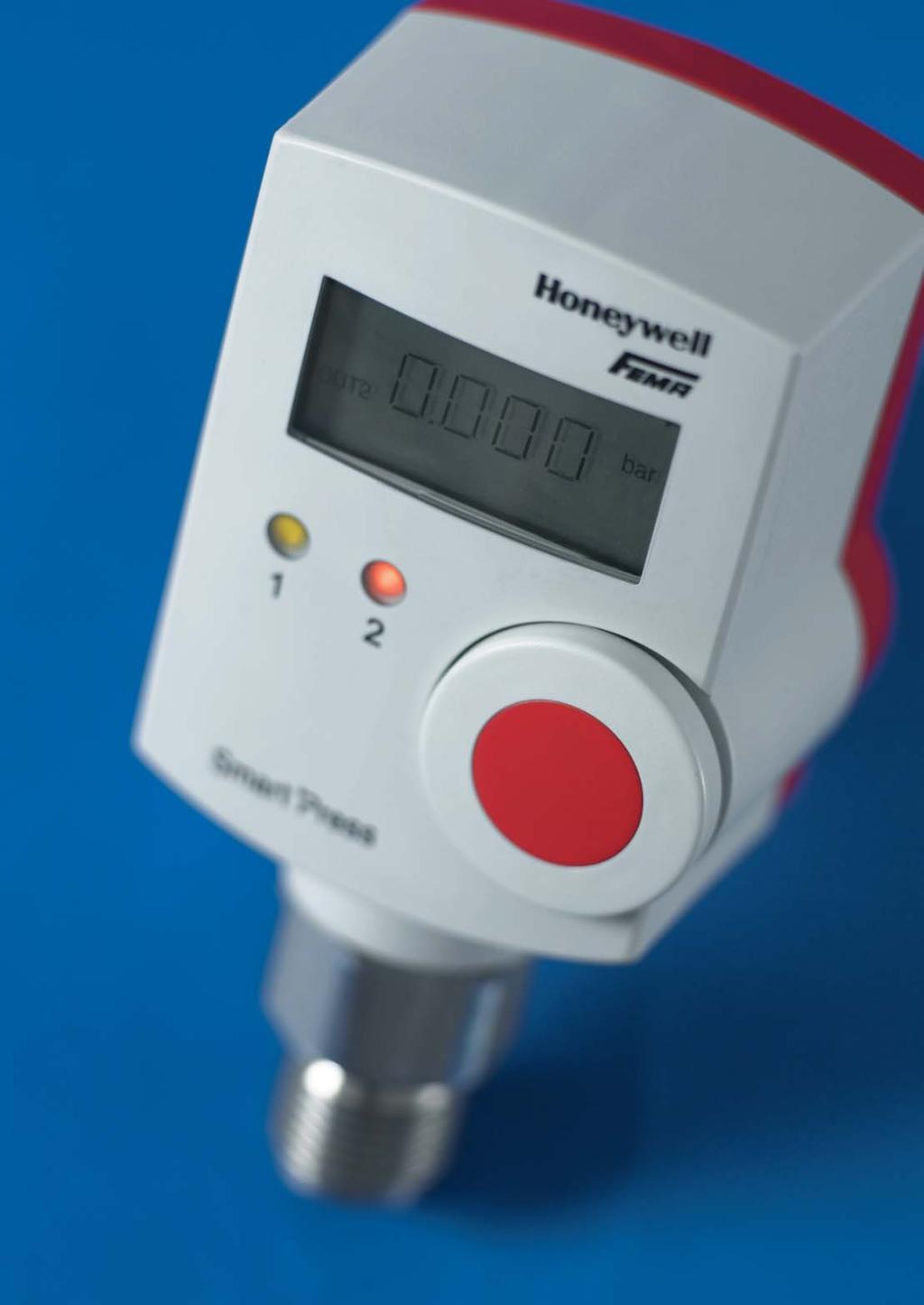

64 Pressure transmitters

65 66 Pressure transmitters Overview Pressure and differential pressure transmitters/ Electrical pressure switches/transmitters Type series Pressure ranges Medium Output signal Operating Remarks/ Page mode Applications F Vacuum up to 40 bar liquid and 0 10 V Mechanical- For general Differential pressure gaseous 0 20 ma inductive applications in up to 10 bar 4 20 ma liquid and Operating ranges (3-conductor gaseous media. continuously system) adjustable PST bar liquid and 0 10 V Piezoresistive Electronic 6 17 gaseous 10 0 V pressure switches stainless steel 4 20 ma with configurable sensors 20 4 ma transmitter 2-channel output switch SN Up to 60 bar liquid and 0 10 V / Piezoresistive Highly accurate Operating ranges gaseous 4 20 ma Hermetically encontinuously (stainless steel (3-conductor-system) capsulated sensor adjustable sensors) 4 20 ma system made of (2-conductor-system) stainless steel. DPT Differential pressure gaseous 0 10 V / Piezoresistive Ventilation and Pa/+50 Pa 4 20 ma air-conditioning up to Pa (3-conductor-system) systems 4 20 ma (2-conductor-system) Accessories Specifications 83

. A metal bellows or diaphragm is exposed to the occurring pressure.")

.")


66 Pressure transmitters Pressure transmitters 67 Type series F Pressure transmitters, mechanical-inductive Operating method Pressure transmitters are used to convert overpressure, vacuum or differential pressure into a proportional electrical signal of 0 10 V, 0 20 ma (4 20 ma). A metal bellows or diaphragm is exposed to the occurring pressure. The pressure-dependent movements of the metal bellows are transmitted free of play to an inductive displacement sensor. The electronic system converts the position of the displacement sensor into a proportional electrical signal (voltage and injected current). General technical information Operating principle Cover Evaluation module ED 1 Sensor module with terminal box Pressure connection A complete transmitter consists of a sensor module with pressure and electrical connections, an evaluation module and a cover. Type series F + ED 1 F + ED 3 Electrical connection Terminal connection Plug connection Additional evaluation modules can be plugged in. Voltage output characteristic Output signal Output signal 0 10 V and 0 20 ma 0 10 V Current output characteristic


67 68 Pressure transmitters for overpressure, vacuum, differential pressure Type series F + ED 1 with terminal connection Pressure FN + ED 1 Differential pressure FHBN + ED 1 Pressure transmitter with 3 conductors with 2 output signals 0 10 V and 0 20 ma Switchable to 2 10 V and 4 20 ma and invertible Plug-in display module AZ 331 Pressure transmitters of the F series produce 0 10 V / 0 20 ma. Both signals are applied to the terminal strip and can be used in parallel. A complete transmitter consists of a sensor parts and the plug-in evaluation module ED 1. Removing the cover gives access to an operator interface for adjusting the operating range. A plug-in digital display AZ 331 is available to display the output signal in any units (voltage / current / pressure / differential pressure). For further details see Datasheet AZ. Characteristic of a transmitter (nominal range) Product Summary Operating range Smallest Max. Sensor Type (nominal range) adjustable permissible material P0 PN operating range pressure (approx. values) Overpressure 0 50 mbar 20 mbar 2.5 bar FN ED mbar 25 mbar 5 bar FN ED mbar 65 mbar 6 bar FN ED mbar 125 mbar 6 bar + FN 05 + ED bar 250 mbar 6 bar FN 1 + ED bar 0.7 bar 16 bar FN 3 + ED 1 Vacuum 1 to 0 bar 250 mbar 6 bar FVN ED 1 1 to 1 bar 500 mbar 6 bar + FVN ED 1 1 to 5 bar 1.5 mbar 25 bar FVN ED to+250 mbar 125 mbar 3 bar FVN ED 1 Differential pressure mbar 125 mbar 10 bar FHBN 05 + ED bar 250 mbar 15 bar FHBN 1 + ED bar 0.7 bar 15 bar + FHBN 3 + ED bar 1.25 mbar 15 bar FHBN 5 + ED bar 2.5 mbar 25 bar FHBN 10 + ED 1 + Accessories Plug-in display module AZ 331 Programmable display APV 630 For differential pressure Valve combination VKD 3, VKD 5 Threaded joint with male adapter union MAU 8 i Note If measured values diverge due to higher static (system) pressure, observe the adjustment instructions on page 71. s Degree of protection: IP 65
 Plug-in display module AZ 331 Pressure and differential pressure transmitters of the F + ED 3 series (with voltage output) are almost identical to versions ED 1.")
 adjustable permissible material P0 PN operating range pressure (approx. values) Overpressure 0 50 mbar 20 mbar 2.5 bar FN 505 + ED 3 0 100 mbar 25 mbar 5 bar 1.")

68 Pressure transmitters for overpressure, vacuum, differential pressure 69 Type series F + ED 3 with plug connection FN Openable plug connection is easy to fit and service, with a transparent front 0 10 V output (invertible) Plug-in display module AZ 331 Pressure and differential pressure transmitters of the F + ED 3 series (with voltage output) are almost identical to versions ED 1. A voltage signal is available at the connection plug. Possible settings are described on pages FHBN Characteristic ED 3 Product Summary Operating range Smallest Max. Sensor Type (nominal range) adjustable permissible material P0 PN operating range pressure (approx. values) Overpressure 0 50 mbar 20 mbar 2.5 bar FN ED mbar 25 mbar 5 bar FN ED mbar 65 mbar 6 bar + FN ED mbar 125 mbar 6 bar FN 05 + ED bar 250 mbar 6 bar FN 1 + ED bar 700 mbar 16 bar FN 3 + ED 3 Vacuum 1 to 0 bar 250 mbar 6 bar FVN ED 3 1 to +1 bar 500 mbar 6 bar + FVN ED 3 1 to 5 bar 1500 mbar 25 bar FVN ED to +250 mbar 125 mbar 3 bar FVN ED 3 Differential pressure mbar 125 mbar 10 bar FHBN 05 + ED bar 250 mbar 15 bar FHBN 1 + ED bar 0.7 bar 15 bar + FHBN 3 + ED bar 1.25 bar 15 bar FHBN 5 + ED bar 2.5 bar 25 bar FHBN 10 + ED 3 + Accessories Plug-in display module AZ 331 For differential pressure Valve combination VKD 3, VKD 5 Threaded joint with male adapter union MAU 8 i Note If measured values diverge due to higher static (system) pressure, observe the adjustment instructions on page 71. s Degree of protection: IP 65
69 70 Pressure transmitters Type series F Technical data All plugged-in modules are powered via the terminal strip of the sensor module (on ED 1) or via the plug connection. The output signal is sent from each module for further evaluation via the same route. The power consumption increases by approx. 1 W for each additional module plugged in. Connection schemes Terminal connection Supply voltage 24 V AC ± 20% or V DC Signal and supply voltage is connected to the sensor module. Power consumption max. 1 W Outputs (short-circuit proof) 0 10 V, 2 10 V (± 1 ma), 0 20 ma, 4 20 ma (3-conductor system) All outputs are invertible. Load impedance max. 750 Ohm. Direction of action Rising pressure produces a rising output signal (default setting). Invert with slide switch 4. Output signal Voltage and current output can also be picked up and used 0 10 V and 0 20 ma simultaneously. Terminals 5 8 are reserved for later expansions and must not be connected as this would destroy the device. Operating mode mechanical, inductive Sensor element Pressure bellows or diaphragm Pressure connection G 1/2 external and G 1/4 internal. On FH types: G 1/4 internal. Cable entry 2 x M 16 x 1.5 Degree of protection IP 65 Installation Directly on the pressure line or mounted on wall with two 4 mm ø screws. Materials see Product Summary. Linearity The maximum linearity error is approx. 1% of full scale. Hysteresis approx. 0.5% nominal range, related to full output 0 10 V or 0 20 ma. Long-term drift 0.2% FS / year Repetition accuracy approx. 0.2% Accuracy class 1.0 Temperature drift Range from C approx. 0.02%/K Range from 0 20 C approx. 0.05%/K Influence of static pressure < = 3%/bar (see adjusting instructions, page 72) Mounting position Vertical. With other mounting positions, the degree of protection and accuracy are different. Ambient temperature 0 to 45 C Max. medium temperature 70 C. Temperatures may reach 85 C for short periods. Higher medium temperatures are possible if the above limit values for the switching device are ensured by suitable measures (e.g.siphon). Storage temperature 20 to +70 C Plug connection! Important: When connecting to control systems with a common AC supply, the ground conductor must be looped through. That is to say, on all devices in the system, the same reference potential must be present at the corresponding ground terminal (terminal 2). In the case of a DC supply, ensure correct polarity. ED 3 output signal 0 10 V
70 Pressure transmitters 71 Type series F Adjustment and operation Operating ranges and output signals are adjustable over a wide range. An outstanding characteristic of the pressure transmitters is the variability of the characteristic curve, which means that the pressure range and output signal can be adapted to any subsequent control system. P0 = starting pressure of nominal range PN = nominal pressure (end point of nominal range) PA = starting pressure of set range PE = end pressure of set range Operator interface ED 1 1 = Setting spindle for setting the final value PE 2 = Setting potentiometer for setting the initial value PA 3 = Slide switch for selecting the output signal 0 20 ma (0 10 V) or 4 20 ma (2 10 V) 4 = Slide switch for inverting the output signal 5 = Slide switch for changing the steepness of the characteristic in a ratio of 8:5. Normal position: 8 For smaller operating ranges (< approx. 70% of the nominal range), select position 5 6 = Plug connector for further evaluation modules Output signals for module ED 1 Basic setting The factory default setting covers the nominal range P0 (usually 0 bar) to PN. Altering the range The range can easily be altered by shifting the end point and adjusting the steepness of the characteristic curve. Inversion The output signal can be inverted by means of a slideswitch. Operator interface ED 3 1 = Setting spindle for setting the final value PE 2 = Setting potentiometer for setting the initial value PA 4 = Slide switch for inverting the output signal 6 = Plug connector for further evaluation modules Output signals for module ED 3 Range alteration and inversion as above. The current signal can be reduced below 4 ma (down to approx. 2.5 ma). If the installation has a fault alarm system, the response threshold should be set below 2.5 ma.
71 72 Pressure transmitters Type series F Setting and testing Altering the operating range To check functioning or change the settings from outside the system, a test set-up is required which meets the following requirements: 1. It must be possible to apply pressure to the pressure transmitter up to the desired final value. The pressure must be displayed by a sufficiently accurate pressure gauge. 2. To display the output signal a voltmeter with a measuring range of 0 10 V (preferably 0 15 V) or an ammeter with a measuring range of 0 20 ma (preferably 0 25 or 0 30 ma) are required. 3. To supply power to the transmitter, a 24 V AC or 24 V DC voltage source is needed. Setting operations must be carried out in the correct sequence 1. Remove the plastic cover 2. Set the slide switches (3) and (4) to the correct position (switch 3 is only present on ED 1) Switch (3): Output signal 0 10 V / 0 20 ma or 4 20 ma / 2 10 V (only on ED 1) Switch (4): Direction of action Switch up rising pressure = rising output signal Switch down (INV): rising pressure = falling output signal 3. Loosen the locking screw above the cover glass (approx. 2 turns anticlockwise) 4. Apply final pressure PE 5. Using a screwdriver, turn the setting spindle (1) to the desired output signal (depending on position of slide switches (3) and (4): 10 V, 20 ma, 0 V, 0 ma, 4 ma) 6. Apply starting pressure PA With the potentiometer (2), adjust the output signal to the desired value (depending on position of slide switches: 0 V, 0 ma, 10 V, 20 ma, 4 ma) 7. Check the setting again and then retighten the locking screw for the setting spindle. Important: Always set the upper final value PE with the setting spindle (1) first, and then the lower initial value PA with the potentiometer (2). Generating an output signal without pressure It can often be very useful to generate an output signal before commissioning the system, in order to check electrical operation, the direction of action and the functioning of downstream control elements. The procedure is as follows: 1. Loosen the four screws on the scale window and remove the cover glass, scale plate and rubber seal. 2. In the lower, wide part of the cut-out in the housing, insert the tip of a small screwdriver underneath the bridge. 3. Carefully move the bridge up and down. When the supply voltage is applied, the output signal should change depending on the movements of the bridge. 4. Check the direction of action. Upward movement of bridge corresponds to rising pressure. 5. Once you have finished testing, carefully screw the parts back on again in the following order: rubber seal, scale plate, cover glass. Caution: In the event of incorrect assembly, IP 65 protection is no longer assured. Adjustment instructions: Correction of effect with static pressure The system in which the FHBN is installed must be filled and exposed to the usual static pressure. A differential pressure must not be active, i.e. no pump operation and no flow. Remove the plastic cover and check slide switches The FHBN is supplied with the correct voltage and the output voltage is displayed. Loosen the spindle locking screw above the inspection window. Adjust setting spindle 1 with a screwdriver until the output signal is 0. Retighten the spindle with the spindle locking screw.


72 Pressure transmitters Dimensioned drawings 73 Type series F Dimensioned drawings Dimensioned drawing no. Types A 1 FN 025-FN FVN 2 FHBN 90 3 FN 505, FN Height of evaluation module = 1 Module height = 34 mm. The dimensions are for the basic device, consisting of sensor and evaluation module. Each further plug-in module increases the overall height by one module unit = 34 mm.


73 74 Pressure transmitters for liquid and gaseous media Type series SN 3 Pressure transmitters, piezoresistive, 3-conductor system Type series SN output signals 0 10 V and 4 20 ma The nominal ranges of types SN 311 mentioned in the Product Summary below can be limited by 50% of the nominal range via setting potentiometers of the evaluation electronics. The smallest settable operating range is indicated in column 2 of the Product Summary. The zero point can likewise be shifted by 50% of the nominal range. Inversion of output signal possible on SN -311 and Technical data Product Summary Pressure connection G 1/2 external, wrench size 27 Cable entry 2 x Pg 9 Degree of protection IP 65 Mounting Directly on pressure line Materials Sensor housing: Pressure diaphragm: Terminal housing: Makrolon Service life 100m cycles (typical) Dimensions See page 73. Operating voltage 24 V AC ± 20% or 24 V 36 V DC Power consumption max. 1 W Synchronization error max. ± 0.3% FS of voltage and current output on SN 311 Load impedance 0 10 V impedance > 10 kohm 4 20 ma impedance 650 Ohm max. ± 0.5% FS max. ± 0.1% FS max. ± 0.5% FS Linearity error Hysteresis Temperature hysteresis Reproducibility max. ± 0.1% FS Overall accuracy 1% Medium temperature 30 to 100 C Compensated range C Temperature drift max. ± 0.04% FS/K Ambient temperature 0 50 C Inversion of On SN 311 output signal and SN 395 LED digital display Powered via (optional) transmitter. AZ 331 No separate supply needed. Operating range Smallest settable Max. permissible Type (nominal range) operating range pressure (bar) (bar) (bar) 2 output signals 0 10 V and 4 20 ma terminal connection, range adjustable SN SN SN SN SN SN SN SN Output signal 0 10 V plug connection, range adjustable via jumpers (50%, 20%) SN SN SN SN SN SN SN SN Connection scheme SN 311 Connection scheme SN 395 Type series SN 395 Output signal 0 10 V Not adjustable, inversion not possible. Plug connection (digital display AZ 331) s Degree of protection: IP 65


74 Pressure transmitters for liquid and gaseous media. 2-conductor system 75 Type series SN -280 The low-voltage plugs on SN transmitters can be opened up. This simplifies fitting and also means that the supply voltage and output signal can be measured directly from the opened plug. As-delivered condition: The transmitters are fully assembled in the factory (sensor + evaluation module + cover) and set to the nominal range. Additional modules and external modules are supplied separately. SN 280 Technical data Electrical Plug connection connection DIN PG 11 Supply voltage 12 V 30 V DC Ambient temperature C Material Housing: Makrolon Sensor: Diaphragm: Degree of protection IP 65 Included accessories Plug DIN Pressure connection G 1/2 external Wrench size 27 Installation Directly on pressure line Linearity 1% FS Compensated range C Response time 10 ms Max. medium C temperature Measuring principle Piezoresistive Mounting Directly on pressure line Output signal 4 20 ma, impedance (UB 10 V) / 0.02 A Overall accuracy 1% FS (fixed-point line) Ambient temperature 0 60 C Direction of action Rising pressure produces rising output signal Accessories Plug-in display AZG 241 Product Summary Operating range Operating range Max. pressure Type (bar) (kpa) (bar) SN SN SN SN SN SN SN SN SN SN SN Connection scheme SN -280 The power supply is connected to terminals 1+ / 2 s Degree of protection: IP 65
75 76 Pressure transmitters Type series SN 3 Operator interface / operating ranges 3-conductor systems (SN 3) Adjusting elements: 1 = zero point 2 = end point INV = direction of action (INVERSION) Optical indication of output signal via LED The LED becomes brighter as the output signal increases. A zero signal can be displayed by briefly operating the INV switch. With output signal 0 and the slide switch in the INV position, the LED is brightly lit. Do not forget to turn the switch back! Operator interface The adjusting elements are accessible after removing the cover glass on the evaluation module. Operating ranges are adjustable over a wide range Basic setting The factory default setting covers the nominal range P0 (usually 0 bar) to PN. P0 = Starting pressure of nominal range PN = Nominal pressure (end point of nominal range) PA = Starting pressure of set range PE = End pressure of set range Altering the range The range can easily be altered by shifting the zero point and adjusting the steepness of the characteristic curve. Observe the correct sequence of adjustment (see next page). Inversion (only on 3-conductor system) The output signal can be inverted with the INV slide switch. Inversion not possible on 2-conductor system.
76 Pressure transmitters 77 Type series SN 3 Setting the operating range, testing Preliminary remark: The transmitters are carefully set in the factory to the nominal range. If the operating range is changed to different values, the guaranteed accuracy no longer applies. The attainable accuracy depends, among other things, on the care taken during adjustment. Warm up the device before making adjustments. Accurate settings are only possible with the device at operating temperature; therefore connect the power supply approximately 10 minutes before starting to make adjustments. Setting operations must be carried out in the correct sequence 1. Apply minimum pressure PA to the sensor and set the output signal to 0 V or 4 ma with potentiometer Apply maximum pressure PE to the sensor. Set output signals to 10 V / 20 ma with potentiometer Check the settings. Important: Always set the zero point with potentiometer 1 first, then set the amplification (end of range) with potentiometer 2. For inversion of the output signal, operate slide switch INV and repeat the setting procedure in the same way. Inversion is only possible on 3-conductor systems. The plug-in digital display AZ facilitates accurate setting Digital display AZ 331 (additional module) can be very useful for setting operating ranges which differ from the nominal range. The digital display (factory setting 0 10 V) plugs into the connector 6 and shows the output signal continuously during the setting process. Device arrangement for calibration and testing from outside the system To check functioning or change the settings from outside the system, a test set-up is required which meets the following requirements: 1. It must be possible to apply pressure to the pressure transmitter up to the desired final value. The pressure must be displayed by a sufficiently accurate pressure gauge. 2. To display the output signal a voltmeter with a measuring range of 0 10 (preferably 0 15 V) or an ammeter with a display range of 0 20 ma (preferably 0 25 or 0 30 ma) are required. 3. To supply power to the transmitter, a 24 VAC or 24 VDC voltage source is needed.
77 78 Pressure transmitters Dimensioned drawings Type series SN Dimensioned drawings SN 311 SN -395/-280 Type series DPT (D) Dimensioned drawings M1:

78 Pressure transmitters for gaseous, non-aggressive media 79 Type series DPT (D) Differential pressure transmitters Applications Air-conditioning and ventilation systems Building automation Environmental protection Fan and ventilator control Valve and shutter control Filter and fan monitoring Liquid and level monitoring Controlling of air flows DPT 1000 D Technical data Pressure media Air, and non-combustible and non-aggressive gases. Pressure Plastic connection piece connection with 6 mm external diameter for measuring hose with 5 mm internal diameter. Connector P 1 for higher pressure, P 2 for lower pressure. Cable entry / M 20 x 1.5, screw termielectrical nals for wires and leads connection with conductor crosssection up to 1.5 mm 2. Degree of protec- IP 54 with cover, tion according to IP 00 without cover DIN Mounting Any mounting position possible, with screws supplied Materials Transmitter housing and pressure connection P2 made of ABS, light grey. Fastening element with pressure connection P1 made of POM, white. Long-term stability -50 Pa Pa 2.5; in % FS/year 1000/2500 Pa 1.5 Repetition accuracy < ± 0.2% of final value Linearity and < ± 1% of end value hysteresis factor Response time switchable 100 ms/1sec Medium and am- 10 C to +70 C bient temperature Permitted air 0 95% non-condensing humidity (2-conductor DC only!) Operating voltage V AC, V DC (2-conductor DC only) Max. current 30 ma for AC, 20 ma consumption for DC Power consumption Max. 1 W Output signal 0 10 V, short-circuitproof to ground 4 20 ma, short-circuitproof 30 ma Housing dimensionsdiameter and weight 85 mm x 58 mm, 130 g Standards and EN 60770, EN conformity Supplied accessories: Optional accessories: 2 m silicone hose, 2 connection pieces with fastening screws, 2 self-tapping screws for fastening the housing DPSL L-shaped bracket for installation turned through 90, e.g. in ceiling area Product Summary Type Default Operating range Over- Bursting Temperature operating extended by pressure pressure error range in Pa jumpers in Pa in kpa in kpa Versions with output voltage 0-10 V DPT not possible ± 5% FS DPT not possible ± 5% FS DPT not possible ± 1% FS DPT not possible ± 1% FS DPT ± 5% FS DPT ± 5% FS DPT ± 2.5% FS DPT ± 1% FS Versions with output voltage 0-10 V and digital display DPT 50 D not possible ± 5% FS DPT 110 D not possible ± 5% FS DPT 550 D not possible ± 1% FS DPT 1100 D not possible ± 1% FS DPT 100 D ± 5% FS DPT 250 D ± 5% FS DPT 500 D ± 2.5% FS DPT 1000 D * ± 1% FS Versions with current output 4-20 ma (3-conductor) DPT not possible ± 5% FS DPT not possible ± 5% FS DPT not possible ± 1% FS DPT not possible ± 1% FS DPT ± 5% FS DPT ± 5% FS DPT ± 2.5% FS DPT ± 1% FS Versions with current output 4-20 ma (3-conductor) and digital display DPT 53 D not possible ± 5% FS DPT 113 D not possible ± 5% FS DPT 553 D not possible ± 1% FS DPT 1103 D not possible ± 1% FS DPT 103 D ± 5% FS DPT 253 D ± 5% FS DPT 503 D ± 2.5% FS DPT 1003 D * ± 1% FS Versions with current output 4-20 ma (2-conductor) DPT not possible ± 5% FS DPT not possible ± 5% FS DPT ± 5% FS DPT ± 5% FS DPT ± 2.5% FS DPT ± 1% FS *pressure displayed in kpa s Degree of protection: IP 54/00

, m 3, cm 3 (volume) etc.")
79 80 Pressure transmitters Adjustable display range Type series AZ Digital display, plugs onto transmitter AZ 331 AZ display modules show the output of a transmitter from the MODUFLEX system on an LED display. On 3-conductor systems the supply and signal voltage is led from the evaluation module via ribbon cable. No additional wiring is needed. The starting and end values of the display can be set anywhere between -50 and +1199, so that any display range can be assigned to any pressure range. The decimal point can be moved with a slide switch. The y-signals of the transmitter can thus be displayed in any unit, e.g. V, ma, bar, mbar, %, C, F, psi, m, cm (filling level), m 3, cm 3 (volume) etc. Technical data Display 3 1/2 digit LED display, 7 mm high, adjustable display range: 50 to Supply voltage 24 VAC or 24 VDC. Via ribbon cable from the basic module Signal voltage (input) 0 10 V. Signal input via ribbon cable from the evaluation module or from other modules. Signal input switchable with slide switch 9. Normal setting: D (output signal from evaluation module is displayed) Decimal point Set with slide switch Factory setting Input signal 0 10 V ± 1 digit Power consumption Max. 1 W Degree of IP 65, in the installed protection state Dimensions Height: 1 module unit = 34 mm By setting the input selector switch 9 to position E, the unit can be made to display signals generated by other modules. Furthermore, in its condition on delivery (factory setting ), the display module can be used for accurately setting the operating range of a transmitter. All controls are accessible from the front, after removing the window. After setting, reinsert the window and press it in evenly. Product Summary Type Suitable for Display Display range AZ conductor systems 3 1/2 digit Controls Potentiometer 7 For setting lower display value (e.g. for y-signal 0%) Potentiometer 8 For setting upper display value (e.g. for y-signal 100%) Input selector switch 9 Position D: Output signal of the evaluation module is displayed (normal setting) Position E: Signal of another module is displayed Decimal point switch 10 For setting the decimal point Decimal point switch 11 Decimal point on/off Operator interface AZ 331 (3 1/2 digit) See above for description of controls.


80 Pressure transmitters Signal separators 81 Type series GT Electrical isolation of analogue transmitter signals The analogue output signals of a transmitter can be electrically isolated from the evaluation device using a signal separator. In this way, interference affecting the transmitter signal can be suppressed and influences caused by ground loops prevented. A signal separator is absolutely essential for transmitters whose output signals have to be transmitted over long distances and for signal lines which are exposed to strong electromagnetic radiation. GT 4 Technical data Supply voltage 24 V AC ± 20% or V DC. Power consumption 1.7 W Inputs Voltage signals, e.g V, 2 10 V, 0 1 V and all voltage ranges between 0 and 10 V Input resistor Ri > 220 kohm Outputs Voltage signals 1:1 from input signal, max. output signal current ± 1 ma Transformation ratio 1:1 Channels 4 channels, usable in parallel Linearity 0.1% FS Transmission error max. 0.1% FS Interference Interference suppressuppression sion N according to EN and EN , class B Degree of protection IP 30 Protection class II Ambient temperature 0 50 C Mounting On mounting rail NS 35/7.5 to DIN The 4-channel configuration and the limitation to voltage signals results in very good value for money. Signal separator GT 4 is designed for 4 input signals between 0 and 10 V (e.g V, 2 10 V, 0 5 V, 0 1 V). The input signal is conveyed to the output terminals in a ratio of 1:1. The input and output are electrically isolated. Product Summary Type Channels Transformation Operating range GT : 1 between 0 and 10 V All 4 channels can be used in parallel and independently of one another; however, the input and output channels are not electrically isolated from one another. Current signals of 0 20 ma or 4 20 ma in the input circuit can likewise be processed if a 500 ohm resistor with the requisite tolerance is attached to the input terminals. A proportional voltage signal is present at the output. The accuracy achieved in the separation of current signals and conversion into voltage signals essentially depends on the accuracy of the 500 ohm resistor that is used. With a resistor value of 500 ± 0.1%, a transmission accuracy of 0.3% is achieved. Schematic diagram Connection scheme Dimensions
 Display range (start and end point)")
81 82 Pressure transmitters Programmable digital display Type series AP with 1 or 2 limit value switches for PT100, PT1000 and voltage and current signals AP... Various routines for setting the following parameters are integrated into the microprocessor-controlled digital display: Measuring range (start and end point) Display range (start and end point) Setting of decimal point 2 limit values (relays) and their hysteresis Relay dropout or pickup delay Scanning of minimum and maximum measured value Rounding up or down of last digit Averaging Technical data Input signals Freely selectable by setting jumpers. See Product Summary Housing front 48 x 96 mm (DIN) Dimension display On APT: C On APV: none Display 3 1/2 digit, LED 12.5 mm, red, automatic sign Display range See Product Summary Other ranges adjustable Decimal point Programmable Measuring rate 2.5 measurements/ second Keyboard lockable with jumper (prevents input of commands) Switching outputs 2 x NO/NC contacts programmable Switching capacity 2 x 230 V, 5 A AC of output relay Supply voltage 230 V, Hz, 3 VA Degree of protection IP 60, DIN (front) Working temperature 10 to +50 C Connection method Lift terminals Front panel cut-out H x W: 44.5 x 90.5 mm Max. installation 115 mm depth All routines and parameters can be set with keys on the front. The switching status of the relays is displayed by LEDs. Setting is buffered. If the supply voltage is interrupted, the set parameters are retained. For powering transmitters, an electrically isolated 24 VDC power supply (max. 30 ma) is available. Product Summary Type Input signals Display range Suitable Stages (programmable) (programmable) for APV V DC 1999 Pressure and 1 switching point APV V DC to temperature 2 switching points 0 20 ma DC transmitters APT 600 Pt 100 / Pt C to Temperature 1 switching point APT C sensors 2 switching points 200 C to Pt 100 / +800 C Pt 1000 Dimensions
Mechanical pressure switches
 18 Technical features / Advantages Diecast aluminium housing IP 54 or IP 65 version also available Wall mounting or directly on the pressure line Switching element (microswitch) Lead sealable setpoint
Pressure Switches Application Guideline
 Pressure Switches Application Guideline Product Overview The Fema Pressure Switch product portfolio provides devices suitable for many applications. The portfolio contains Special functions and equipment
Mechanical pressure switches Tested to ATEX 94/9/EC. II 2G Ex d e IIC T6 Gb II 1/2D Ex ta/tb IIIC T80 ºC Da/Db
 Ex-DWR25 Technical data Pressure connection External thread G 1/2 (pressure gauge connection) to DIN 16 288 and internal thread G 1/4 to ISO 228 Part 1 (for gas applications internal thread permissible
Mechanical pressure switches Tested to ATEX 94/9/EC. II 2G Ex d e IIC T6 Gb II 1/2D Ex ta/tb IIIC T80 ºC Da/Db. SIL 2 according IEC
 Ex-DDCM1 (stainless steel sensor) Technical data Pressure connection Internal thread G 1/4 Switching device Robust housing (700) made of seawaterresistant diecast aluminium GD Al Si 12. Protection class
Mechanical pressure switches Tested to ATEX 94/9/EC. II 2G Ex d e IIC T6 Gb II 1/2D Ex ta/tb IIIC T80 ºC Da/Db. SIL 2 according IEC
 Ex-DWR25 Technical data Pressure connection External thread G 1/2 (pressure gauge connection) to DIN 16 288 and internal thread G 1/4 to ISO 228 Part 1 (for gas applications internal thread permissible
Mechanical pressure switches Liquids and gases. Negative pressure switches (vacuum switches)
") 44 Liquids and gases VCM/VNM Negative pressure switches (vacuum switches) FEMA negative pressure switches detect the pressure difference relative to atmospheric pressure. All data relating to the switching
44 Liquids and gases VCM/VNM Negative pressure switches (vacuum switches) FEMA negative pressure switches detect the pressure difference relative to atmospheric pressure. All data relating to the switching
Mechanical pressure switches Tested to ATEX 94/9/EC. II 2G Ex d e IIC T6 Gb II 1/2D Ex ta/tb IIIC T80 ºC Da/Db
 68 Tested to ATEX 94/9/EC Ex-VCM/Ex-VNM II 2G Ex d e IIC T6 Gb II 1/2D Ex ta/tb IIIC T80 ºC Da/Db FEMA negative pressure switches detect the pressure difference relative to atmospheric pressure. All data
Mechanical Pressure Switches for overpressure, vacuum pressure and differential pressure
 Mechanical Pressure Switches for overpressure, vacuum pressure and differential pressure Switching range: -250 +100 mbar, 1 16 mbar to 16 63 bar Temperature: max. 70 C Material: Copper, brass, stainless
Mechanical Pressure Switches for overpressure, vacuum pressure and differential pressure
 Mechanical Pressure Switches for overpressure, vacuum pressure and differential pressure Switching range: -250 +100 mbar, 1 16 mbar to 16 63 bar Temperature: max. 70 C Material: Copper, brass, stainless
Product Catalog. Pressure Switches. Pressure Transmitters. Thermostats. Temperature Transmitters. Solenoid Valves TÜV DVGW ATEX.
 f Product Catalog Pressure Switches Pressure Transmitters Thermostats Temperature Transmitters Solenoid Valves TÜV DVGW ATEX Zulassung in Vorbereitung Flow Monitors Featuring New products H Electronic
Mechanical Pressure Switches for overpressure, vacuum pressure and differential pressure
 Mechanical Pressure Switches for overpressure, vacuum pressure and differential pressure Switching range: -250 +100 mbar, 1 16 mbar to 16 63 bar Temperature: max. 70 C Material: Copper, brass, stainless
Mechanical pressure switches Liquids and gases. Pressure switches and vacuum switches with stainless steel sensors (1.4571)
") DNS3-201 Technical data Pressure connection External thread G 1/2 (pressure gauge connection) according to DIN 16 288 and internal thread G 1/4 according to ISO 228 Part 1. Switching device Robust housing
DNS3-201 Technical data Pressure connection External thread G 1/2 (pressure gauge connection) according to DIN 16 288 and internal thread G 1/4 according to ISO 228 Part 1. Switching device Robust housing
Mechanical pressure switches Tested to PE Directive 97/23/EC
 60 Tested to PE Directive 97/23/EC DWR Pressure limiters Especially suitable as a pressure limiter for fuel gases (DVGW work sheet G 260) and liquid fuels (e.g. fuel oil), as well as for steam systems
Mechanical pressure switches Tested to PE Directive 97/23/EC. Maximum pressure limiters for liquid gas installations
 Tested to PE Directive 97/23/EC FD Maximum pressure limiters for liquid gas installations Pressure limiters of the FD series are constructed in accordance with the special directives for liquid gas engineering.
Mechanical pressure switches Liquids and gases. Pressure switches and vacuum switches with stainless steel sensors (1.4571)
") DNS3-201 Technical data Pressure connection External thread G 1/2 (pressure gauge connection) according to DIN 16 288 and internal thread G 1/4 according to ISO 228 Part 1. Switching device Robust housing
DNS3-201 Technical data Pressure connection External thread G 1/2 (pressure gauge connection) according to DIN 16 288 and internal thread G 1/4 according to ISO 228 Part 1. Switching device Robust housing
Tested to PE Directive 97/23 EC
 DWR625 Technical data Pressure connection External thread G 1/2 (pressure gauge connection) to DIN 16 288 and internal thread G 1/4 to ISO 228 Part 1 (for gas applications internal thread permissible only
Mechanical pressure switches Tested to PE Directive EU/2009/142/EC. Pressure monitors for fuel gases
 54 Tested to PE Directive EU/2009/142/EC DGM Pressure monitors for fuel gases DVGW tested to DIN EN1854 Gas pressure monitors are suitable for all gases in accordance with DVGW work sheet G260 and for
Mechanical pressure switches Tested to PE Directive 97/23/EC
 DWR625 Technical data Pressure connection External thread G 1/2 (pressure gauge connection) to DIN 16 288 and internal thread G 1/4 to ISO 228 Part 1 (for gas applications internal thread permissible only
Mechanical Pressure Switches for overpressure, vacuum pressure and differential pressure
 Mechanical Pressure Switches for overpressure, vacuum pressure and differential pressure measuring monitoring analysing Switching range: -250 +100 mbar, 1 16 mbar to 16 63 bar Temperature: max. 70 C Material:
Mechanical Pressure Switches for overpressure, vacuum pressure and differential pressure
 Mechanical Pressure Switches for overpressure, vacuum pressure and differential pressure measuring monitoring analysing Switching range: -250 +100 mbar, 1 16 mbar to 16 63 bar Temperature: max. 70 C Material:
Mechanical Pressure Switches for overpressure, vacuum pressure and differential pressure
 Mechanical Pressure Switches for overpressure, vacuum pressure and differential pressure Switching range: -250 +100 mbar, 1 16 mbar to 16 63 bar Temperature: max. 70 C Material: Copper, brass, stainless
DM01. Please visit our website: Battery Powered Precision Digital Gauge. Stainless Steel Sensor. class 0.05
 DM0 Battery Powered Stainless Steel Sensor class 0.05 Nominal pressure from 0 00 mbar up to 0... 00 bar Special characteristics modular sensor concept data logger graphic display stainless steel housing
ETd 04. Battery Powered Precision Digital Gauge. Stainless Steel Sensor. Type: ETd 04. class 0.05
 Battery Powered Stainless Steel Sensor class 0.05 Nominal pressure from 0 100 mbar up to 0... 400 bar Special characteristics modular sensor concept data logger graphic display stainless steel housing
IDL01. Battery Powered Precision Digital Gauge for Leak Testing. Stainless Steel Sensor. class 0.05
 IDL0 Battery Powered Precision Digital Gauge for Leak Testing Stainless Steel Sensor class 0.05 Nominal pressure from 0 00 mbar up to 0... 00 bar Special characteristics modular sensor concept data logger
DM01. Battery Powered Precision Digital Gauge. Stainless Steel Sensor. class 0.05
 Battery Powered Stainless Steel Sensor class 0.05 Nominal pressure from 0 00 mbar up to 0... 00 bar Special characteristics modular sensor concept data logger graphic display stainless steel housing Ø
Pressure Monitoring Flow Monitoring
 Pressure Monitoring Flow Monitoring Pressure Switches, Pressure Monitors, Pressure Limiters Flow Monitors, Airflow Monitors H f Steam Hot water Fuel gases Liquid fuels (e. g. heating oil) Pressure vessels
2 Overview. SITRANS P measuring instruments for pressure. Transmitters for gage and absolute pressure. Z series for gage pressure
 Z series for gage pressure Overview Design The main components of the pressure transmitter are: Brass housing with silicon measuring cell and electronics plate Process connection Electrical connection
SITRANS P measuring instruments for pressure
 SITRANS P measuring instruments for pressure Z series for gage pressure Siemens AG 008 Overview Design The main components of the pressure transmitter are: Brass housing with silicon measuring cell and
Gas density monitor With integrated transmitter Model GDM-100-TI
 SF 6 gas solutions Gas density monitor With integrated transmitter Model GDM-100-TI grid Products WIKA data sheet SP 60.05 for further approvals see page 5 Applications Gas density monitoring of closed
Pressure Switch Pressure Limiter
 Assembly and Operating Instructions Pressure Switch Pressure Limiter Basic models Additional functions DCM......-203 DNM......-205 DNS......-206 VCM...,VNM......-307 VNS......-213 Important safety information!
Technical Data Sheet MF010-O-LC
 Technical Data Sheet MF010-O-LC - 1 - 1. Properties The oxygen measuring system MF010-O-LC determines the oxygen content in gas mixtures up to a temperature of 250 C. It is particularly suitable for the
Mass Flow Controller (MFC) for Gases
 for Gases") Mass Flow Controller (MFC) for Gases Bypass MFC with capillary technology for nominal flow rates from 5 ml N /min to 15 l N /min Applicable for aggressive gases Compact design and digital communication
Mass Flow Controller (MFC) for Gases Bypass MFC with capillary technology for nominal flow rates from 5 ml N /min to 15 l N /min Applicable for aggressive gases Compact design and digital communication
OPTIBAR P 1010 C Technical Datasheet
 Technical Datasheet Pressure transmitter with recessed diaphragm for general applications Wide variety thanks to modular design Measuring ranges up to 250 bar / 3750 psi High overload and temperature stability
Electropneumatic Positioner and Pneumatic Positioner Type 3760 JIS
 Electropneumatic Positioner and Pneumatic Positioner Type 3760 Application Single-acting positioners for direct attachment to pneumatic control valves. Supplied with an electric input signal of 4 to 20
Pneumatic high-pressure controller Model CPC7000
 Calibration technology Pneumatic high-pressure controller Model CPC7000 WIKA data sheet CT 27.63 Applications Healthcare and avionics industry Industry (laboratory, workshop and production) Transmitter
Mass Flow Controller (MFC) for Gases
 for Gases") Mass Flow Controller (MFC) for Gases Type 8713 can be combined with... Direct flow measurement by MEMS- Technology for nominal flow rates from 1 ml N /min to 8 l N /min (N 2 ) High accuracy and repeatability
Mass Flow Controller (MFC) for Gases Type 8713 can be combined with... Direct flow measurement by MEMS- Technology for nominal flow rates from 1 ml N /min to 8 l N /min (N 2 ) High accuracy and repeatability
Pressure switch Type BCP
 Data sheet Pressure switch Type BCP The BCP type is a series of dedicated switches for safety and monitoring of steam and hot water boilers. The BCP incorporates a single-pole changeover microswitch where
Instruction Manual Differential Pressure Transmitter
 DE61 Instruction Manual Differential Pressure Transmitter Table of Contents 1. Safety Instructions 2. Intended Applications 3. Product Description and Functions 4. Installation 5. Commissioning 6. Maintenance
Pneumatic high-pressure controller Model CPC7000
 Calibration technology Pneumatic high-pressure controller Model CPC7000 WIKA data sheet CT 27.63 Applications Automotive and avionics industry Industry (laboratory, workshop and production) Transmitter
Electropneumatic Positioner and Pneumatic Positioner Type 3760 JIS
 Electropneumatic Positioner and Pneumatic Positioner Type 3760 Application Single-acting positioners for direct attachment to pneumatic control valves. An electric standardized signal of 4 to 20 ma or
1 Overview. Pressure Measurement Transmitters for basic requirements. 1/16 Siemens FI SITRANS P220 for gauge pressure
 Siemens AG 204 Overview The pressure transmitter SITRANS P220 measures the gauge pressure of liquids, gases and vapors. Stainless steel measuring cell, fully welded Measuring ranges 2.5 to 600 bar (36.3
How to specify a product. Process Sensors and Mechanical Instruments
 How to specify a product Process Sensors and Mechanical Instruments Keep the overview. Here is some guideline information on how to specify our products. Intended as supplementary help to specification
SCH. Mechanical Pressure Switches. for overpressure, vacuum pressure and differential pressure
 Mechanical Pressure Switches for overpressure, vacuum pressure and differential pressure measuring monitoring analysing SCH P3 OO Switching range: -1... + 0.1 bar - 250... +100 mbar, 1... 16 mbar a 16...
![[Instruments for vacuum measurement, checking and adjustment] 3](/thumbs/94/121874202.jpg "[Instruments for vacuum measurement, checking and adjustment] 3")
DMK 458. Pressure Transmitter for Marine and Offshore. Ceramic Sensor. accuracy according to IEC 60770: standard: 0.25 % FSO option: 0.
 Pressure Transmitter for Marine and Offshore Ceramic Sensor accuracy according to IEC 60770: standard: 0.5 % FSO option: 0. % FSO Nominal pressure from 0... 40 mbar up to 0... 0 bar Output signals -wire:
Pressure Switches. Assembly and Operating Instructions. Important safety information!
 Assembly and Operating Instructions Pressure Switches Basic models Additional functions DCM... -203-574 DNM... -205-575 DNS... -206-576 VCM..., VNM... -307-577 VNS... -213-513 DDCM... -217...-563 Ex-...
Mass Flow Meter (MFM) for Gases
 for Gases") 873 Mass Flow Meter (MFM) for Gases Direct flow measurement by MEMS- Technology for nominal flow rates from 1 ml N /min to 8 l N /min (N 2 ) High accuracy Short response time Compact design and digital
873 Mass Flow Meter (MFM) for Gases Direct flow measurement by MEMS- Technology for nominal flow rates from 1 ml N /min to 8 l N /min (N 2 ) High accuracy Short response time Compact design and digital
Pressure Measurement. Transmitters for basic requirements SITRANS P Z for gauge pressure. 2/4 Siemens FI Overview
 f gauge pressure Siemens AG 010 Overview Design The main components of the pressure transmitter are: Brass housing with silicon measuring cell and electronics plate Process connection Electrical connection
Precision digital pressure gauge Model CPG1000
 Calibration technology Precision digital pressure gauge Model CPG1000 WIKA data sheet CT 10.01 Applications Oil and gas industry Maintenance and service facilities Calibration service companies and service
LMP 307. Stainless Steel Probe. Stainless Steel Sensor. accuracy according to IEC 60770: standard: 0.35 % FSO option: 0.25 % / 0.
 LMP 07 Stainless Steel Sensor accuracy according to IEC 60770: standard: 0.5 % FSO option: 0.5 % / 0. % FSO Nominal pressure from 0... mho up to 0... 50 mho Output signals -wire: 4... 0 ma -wire: 0...
High-performance submersible pressure transmitter For level measurement Model LH-20
 Electronic pressure measurement High-performance submersible pressure transmitter For level measurement Model LH-20 WIKA data sheet PE 81.56 Applications Deep well and borehole measurements Groundwater
1 Overview. Pressure Measurement Single-range transmitters for general applications. 1/16 Siemens FI US Edition
 Siemens AG 206 Overview Design Device structure without explosion protection The pressure transmitter consists of a piezoresistive measuring cell with a diaphragm installed in a stainless steel enclosure.
MANUAL KPS Pressure Control Valve
 TetraTec Instruments GmbH Gewerbestrasse 8 71144 Steinenbronn Deutschland E-Mail: info@tetratec.de Tel.: 07157/5387-0 Fax: 07157/5387-10 MANUAL Pressure Control Valve *** VERSION 1.0 *** Update: 17.11.2006
High-performance submersible pressure transmitter For level measurement Model LH-20
 Electronic pressure measurement High-performance submersible pressure transmitter For level measurement Model LH-20 WIKA data sheet PE 81.56 Applications Deep well and borehole measurements Groundwater
x act i Precision Pressure Transmitter for Food Industry, Pharmacy and Biotechnology Stainless Steel Sensor accuracy according to IEC 60770: 0.
 Precision Pressure Transmitter for Food ndustry, Pharmacy and Biotechnology Stainless Steel Sensor accuracy according to EC 60770: 0. % FSO Nominal pressure from 0... 400 mbar up to 0... 40 bar Output
Bourdon tube pressure gauge for diaphragm seals
 Bourdon tube pressure gauge for diaphragm seals and switch function, Type series BR42.. Features Bourdon tube pressure gauge for diaphragm seal and switch function Nominal range -1 3 bar to -1 15 bar,
Level switches Series LD Vibrating fork level switch for liquids and solids
 Level switches Series LD Vibrating fork level switch for liquids and solids Robust and compact Suitable for liquids (model LD61) and solids (model LD60) No moving parts, low maintenance Corrosion resistant
Technical Data. General specifications. Rated operating distance s n 5 mm
 0102 Model Number Features 5 mm flush Usable up to SIL 2 acc. to IEC 61508 Accessories EXG-18 Quick mounting bracket with dead stop BF 18 Mounting flange, 18 mm Technical Data specifications Switching
Pressure Measurement Single-range transmitters for general applications
 Siemens A 207 Overview Application The SITRANS P Compact pressure transmitter is designed for the special requirements of the food, pharmaceutical and biotechnology industries. The use of high-grade materials
TRZ 03-K Volumeter. Proven Technology. Superior Performance. TRZ 03-K Volumeter is a Turbine Gas Flowmeter for Secondary Gas Metering.
 TRZ 0-K Volumeter TRZ 0-K Volumeter is a Turbine Gas Flowmeter for Secondary Gas Metering. TRZ 0-K Turbine Gas Flowmeter continues the tradition of Honeywell s field-proven turbine meter technology, delivering
SITRANS. Pressure transmitter SITRANS P, Z series for gauge and absolute pressure. Introduction. Safety instructions 2.
 Introduction 1 Safety instructions 2 SITRANS Pressure transmitter SITRANS P, Z series for gauge and absolute pressure 7MF1564 Description 3 Assembly and connection 4 Technical data 5 Dimensional drawings
Precision pressure sensor Basic version Model CPT6020
 Calibration Precision pressure sensor Basic version Model CPT6020 WIKA data sheet CT 25.13 Applications Calibration technology High-accuracy pressure monitoring Pressure sensing in critical applications
BSP Pressure Sensor Balluff GmbH, BA Marco Zorcic.
 1 2 Standard Pressure Sensor with display Overview Pressure Range Relative nominal Overload Burst Permitted negative -1..2 bar 2 bar 4 bar 10 bar -1..10 bar 10 bar 20 bar 35 bar 0..2 bar 2 bar 4 bar 10
High-performance submersible pressure transmitter For level measurement in hazardous areas Model LH-20
 Electronic pressure measurement High-performance submersible pressure transmitter For level measurement in hazardous areas Model LH-20 WIKA data sheet PE 81.56 Applications Deep well and borehole measurements
Dimensions. Technical Data General specifications Switching element function Rated operating distance s n 5 mm
 Dimensions M18x1 37 40 4 0102 24 LED Model Number Features 5 mm embeddable Usable up to SIL2 acc. to IEC 61508 Connection BN BU Accessories L+ L- EXG-18 Quick mounting bracket with dead stop BF 18 Mounting
AMS 6916 Board mount pressure sensor with ratiometric analog output
 FEATURES Piezoresistive pressure sensor with amplified analog output Calibrated and temperature compensated Ratiometric voltage output, 0.5 4.5 V Digital signal conditioning, 12 bit output resolution Differential,
JUMO dtrans p30 Pressure Transmitter
 609 Fulda, Germany Postal address: 605 Fulda, Germany Phone: +49 661 600-0 Fax: +49 661 600-607 Phone: +44 179 6 55 Data Sheet 40466 Page 1/6 JUMO dtrans p0 Pressure Transmitter General application Pressure
Operating instructions Safety Rope Emergency Stop Switches ZB0052 / ZB0053 ZB0072 / ZB0073
 Operating instructions Safety Rope Emergency Stop Switches UK ZB0052 / ZB0053 ZB0072 / ZB0073 7390878 / 02 03 / 2011 Contents 1 Safety instructions...3 2 Installation / set-up...4 2.1 Applications...4
Operating Instructions for Intrinsically Safe Pressure Transmitters Series DMG/******** for Hazardous Application in Coal Mining Industry
 Operating Instructions for Intrinsically Safe ressure Transmitters Series DMG/******** for Hazardous Application in Coal Mining Industry Contents 1. Introduction 2. Abbreviations, symbols 3. Important
x act i Precision- Pressure Transmitter for Food Industry, Pharmacy and Biotechnology Stainless Steel Sensor
 Precision- Pressure Transmitter for Food ndustry, Pharmacy and Biotechnology Stainless Steel Sensor accuracy according to EC 60770: 0. % FSO Nominal pressure from 0... 400 mbar up to 0... 40 bar Output
Technical Datasheet. D Series SMART Pressure Transmitter Model: DPC D-Series. Key Features. Series Overview. Product applications
 Technical Datasheet D Series SMART Pressure Transmitter Model: DPC-2000 Key Features ATEX - Flameproof and Intrinsically Safe IECEx - Flameproof and Intrinsically Safe SIL 2 certificate Compliant to NAMUR
Type N-10, N-11 Hazardous Area Non-incendive Transmitters
 Electronic Pressure Catalog > Hazardous Area > N-10, N-11 Type N-10, N-11 Hazardous Area Non-incendive Transmitters Applications Natural gas compressors Wellhead monitoring Pipeline pressure General industrial
Dimensions. Technical Data General specifications Switching element function Rated operating distance s n 10 mm
 Dimensions M30x1,5 5 40 37 0102 Model Number 36 LED Features Comfort series 10 mm embeddable Connection BN BU Accessories BF 30 Mounting flange, 30 mm L+ L- Technical Data specifications Switching element
Programmable pressure and temperature transmitters PTM/RS485
 Programmable pressure and temperature transmitters PTM/RS485 Version: 03-28-2012 Technical Specifications Pressure measuring range (bar) 0.1... 0.5 > 0.5 2 > 2 25 Overpressure 3 bar 3 x FS ( 3 bar) 3 x
Technical Data. General specifications Switching element function Rated operating distance s n 2 mm
 0102 Model Number Features 2 mm flush Usable up to SIL 2 acc. to IEC 61508 Accessories EXG-12 Quick mounting bracket with dead stop BF 12 Mounting flange, 12 mm Technical Data specifications Switching
ATM/Ex - Analog Pressure Transmitter
 Pressure Transmitter - ATEX certified ATM/Ex - Analog Pressure Transmitter CUSTOMER BENEFITS Certificate: ATEX & EAC Fast customization thanks to configurable product design Demountable electrical connector
Technical Data. Dimensions
 0102 Model Number Features 2 mm flush Usable up to SIL2 acc. to IEC 61508 Technical Data specifications Switching element function NAMUR, NC Rated operating distance s n 2 mm Installation flush Output
FTC130 Transmitter. Operating Manual
 Seite 1 von 11 FTC130 Transmitter Fast Thermal Conductivity Analyzer Operating Manual 1.09KD180724CWI1V05 Messkonzept GmbH Seite 2 von 11 1. Intended Use... 3 2. Description... 4 3. Measuring gases and
Programmable pressure and temperature transmitters PTM/RS485
 Programmable pressure and temperature transmitters PTM/RS485 Version: 26.06.2014 Technical Specifications Pressure measuring range (bar) 0.1... 0.5 > 0.5 2 > 2 25 Overpressure 3 bar 3 x FS ( 3 bar) 3 x
DK46 - DK800 Supplementary instructions
 DK46 - DK800 Supplementary instructions Variable area flowmeter Device category II2G with electrical internals Additional Ex manual KROHNE CONTENTS DK46 - DK800 1 Safety instructions 3 1.1 General... 3
Level switches Series LD Vibrating fork level switch for liquids and solids
 Level switches Series LD Vibrating fork level switch for liquids and solids Robust and compact Suitable for liquids (model LD61) and solids (model LD60) No moving parts, low maintenance Corrosion resistant
Pressure Calibrators. Series PC..., PM...
 Pressure Calibrators Series PC..., PM... SIKA-Precision Pressure Calibrators, Series PC..., PM... We help you, if you are under pressure! Pneumatic pressure calibrators PM 25 A, PM 25 D, PM 110 PIC pressure
Technical Data. Dimensions
 0102 Model Number Features 10 mm flush Shielded PUR cable for oil and gas sector Accessories BF 30 Mounting flange, 30 mm Technical Data specifications Switching function Normally closed (NC) Output type
Electronic gas volume corrector model DGVC-04
 Electronic gas volume corrector model DGVC-04 1. Introduction The following user s manual gives information about the installation, configuration, usage and storage of the electronic gas volume corrector
Types and approvals. Page 1/6. Data Sheet
 Page 1/6 Panel-mounting Thermostats EM Series as: Protection temperature monitor STW (STB) Protection temperature limiter STB tested to DIN 3440 and Pressure Equipment Directive 97/23/EC Brief description
Technical Data. Dimensions
 00 Model Number Features mm flush Usable up to SIL acc. to IEC 6508 Accessories V-G Female connector, M, -pin, field attachable V-W Female connector, M, -pin, field attachable V-G-N-M-PUR Female cordset,
FLAMMABLE GAS SENSOR/TRANSMITTER
 FLAMMABLE GAS SENSOR/TRANSMITTER Plant safety protection for flammable gases. F E A T U R E S Fixed gas monitoring for point source hazards and perimeter protection in arduous duty and exposed locations.
ATM/Ex - Intrinsically Safe Analog Pressure Transmitter - ATEX / IECEx Certified
 Intrinsically safe pressure transmitters ATM/Ex - Intrinsically Safe Analog Pressure Transmitter - ATEX / IECEx Certified CUSTOMER BENEFITS Certificate: ATEX & IECEx Fast customization thanks to configurable
Instruction Manual Contact Pressure Vacuum Gauge
 MS10 Instruction Manual Contact Pressure Vacuum Gauge Table of Contents 1. Safety Instructions 2. Intended Applications 3. Product Description and Functions 4. Installation 5. Commissioning 6. Maintenance
Supplementary Operator s Manual 42/24-14 EN Rev. 3
 Advance Optima Continuous Gas Analyzers AO2000 Series with Uras26, Magnos206, Caldos25, Caldos27 Designed per Category 3G for Measurement of Flammable Gases ( Safety Concept ) and Non-flammable Gases Supplementary
AMS 2710 PCB pressure sensor module with V output
 FEATURES Universal pressure sensor module with 0.. 10 V voltage output Fully calibrated and temperature compensated sensor module Variants for (bidirectional) differential, gage, absolute and barometric
deltaflowc deltaflowc Venturi or Probe
 deltaflowc Mass Flowmeter for Gases - Multivariable with ultra fast dp, p and T-sensors - Compact, accurate and user-friendly - Ideal for OEMs deltaflowc Venturi or Probe Precise mass flow metering deltaflowc
High-performance submersible pressure transmitter For level measurement Model LH-10
 Electronic pressure measurement High-performance submersible pressure transmitter For level measurement Model LH-10 WIKA data sheet PE 81.09 Applications Level measurement in rivers and lakes Deep well
ATM/GR. Electronic pressure switches CUSTOMER BENEFITS
 Electronic pressure switches ATM/GR CUSTOMER BENEFITS Pressure sensor with integrated switching contacts Modular sensor structure (any process and electrical connections can be combined) Manual readjustment
Digital pressure gauge Model CPG500
 Calibration technology Digital pressure gauge Model CPG500 WIKA data sheet CT 09.01 Applications Calibration service companies and service industry Measurement and control laboratories Quality assurance
2600T Series Pressure Transmitter Models 264DC Differential and 264HC Gage Level Transmitters. Kent-Taylor
 INDUSTRIAL INSTRUMENTS AND CONTROLS SPECIALIST Kent-Taylor 2600T Series Pressure Transmitter Models 264DC Differential and 264HC Gage Level Transmitters Features Include Base accuracy : ±0.075% Span limits
Technical Data. Dimensions
 0102 Model Number Features Comfort series 15 mm non-flush Stainless steel housing Accessories BF 30 Mounting flange, 30 mm Technical Data specifications Switching element function NAMUR, NC Rated operating
Pressure Transmitters 36 F-27839
 Pressure Transmitters 36 F-27839 SPD310/SPD360 Air Differential schneider-electric.com 37 SPD310/SPD360 SPD310/SPD360 differential pressure transmitters are intended for use in air handling systems for
KERN EG/EW Version /02
 E KERN EG/EW Version 1.5 07/02 Operating Instructions Electronic Precision Balances Contents 1 TECHNICAL DATA... 20 2 UNPACKING AND STANDARD ACCESSORIES... 23 3 SETTING UP THE BALANCE... 23 4 EXTERNAL
pressure regulator Zero pressure regulator Proportional pressure regulator Compressed air-controlled
 Pressure regulator FRNG Zero pressure regulator Proportional pressure regulator Compressed air-controlled pressure regulator 4.14 Printed in Germany Edition 01.18 Nr. 219 570 Technical description The