4400H TwinHybrid Gas Seal
|
|
|
- Natalie Mason
- 5 years ago
- Views:
Transcription

1 INSTALLATION, OPERATION and REUILD INSTRUCTIONS 4400H TwinHybrid Gas Seal Installation, Operation and Rebuild Instructions TALE OF CONTENTS 1.0 Cautions Transport and Storage Description Parts Identification Operating Parameters Standard Materials Intended Use Dimensional Data Preparation for Installation Equipment H TwinHybrid Gas Seal Seal Installation Commissioning/Equipment Start-up Decommissioning/Equipment Shut Down Spare Parts Seal Maintenance and Repair H Trouble Shooting H TwinHybrid Gas Seal Rebuild Instructions Seal Data Reference (Insert seal and equipment data here for future reference) ITEM # SEAL (Example: 4400H 50 mm SSC/C/FKM/S) INSTALLATION DATE
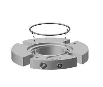
2 1.0 CAUTIONS These instructions are general in nature. It is assumed that the installer is familiar with seals and certainly with the requirements of their plant for the successful use of mechanical seals. If in doubt, get assistance from someone in the plant who is familiar with seals or delay the installation until a seal representative is available. All necessary auxiliary arrangements for successful operation (heating, cooling, flushing) as well as safety devices must be employed. These decisions are to be made by the user. The decision to use this seal or any other Chesterton seal in a particular service is the customer s responsibility. Do not touch the mechanical seal for any reason while it is operating. Lockout or uncouple the driver prior to personal contact with the seal. Do not touch the mechanical seal while it is in contact with hot or cold fluids. Ensure that all the mechanical seal materials are compatible with the process fluid. This will prevent possible personal injury. 2.0 TRANSPORT AND STORAGE Transport and store seals in their original packaging. Mechanical seals contain components that may be subject to alteration and ageing. It is therefore important to observe the following conditions for storage: Dust free environment Moderately ventilated at room temperature Avoid exposure to direct sunlight and heat. For elastomers, storage conditions according to ISO 2230 should be observed. 3.0 DESCRIPTION 3.1 Parts Identification Figure , 31-34, 37 (not shown in this view) KEY 1 Sleeve Assembly 2 Shaft O-Ring 3 Gasket 4 Rotary O-Ring 5 Rotary Seal Ring 6 Adapter 7 Rotary Cushion O-Ring 8 Stationary Seal Ring 9 Gland 10 Inter Gland O-Ring 11 OD Stationary O-Ring 12 ID Stationary O-Ring 13 Pusher Plate 14 Lock Ring 15 Centering Clip 16 Socket Head Cap Screw 17 Adjusting Screw 18 Screw O-Ring 19 Inboard Spring 20 Diaphragm 21 Actuator 22 Snap Ring 23 Seat O-Ring 24 Seat 25 all 26 Outboard Spring 27 Dog Point Set Screw 28 Cup Point Set Screw 29 Gland Screws 30 Spring 31 1/4" Pipe Plug 32 1/8" Pipe Plug 33 3/8" Pipe Plug 34 Cap Plug 35 Filter Disk 36 Retaining Clip 37 Support Gasket 2
3 3.0 DESCRIPTION cont. 3.2 Operating Parameters* Speed Limits: 25 m/s (5000 fpm) Maximum 1,3 m/s (250 fpm) Minimum 3.3 Standard Materials Faces: Carbon Stationary Seal Ring Sintered Silicon Carbide Rotary Seal Ring Pressure Limits: 710 Torr (28" Hg) to 20 bar g (300 psig) 25 mm 65 mm (1.000" ") 510 Torr (20" Hg) to 17 bar g (250 psig) 70 mm 90 mm (2.750" 3.625") Temperature Limits: To 260 C (500 F) Maximum (elastomers) Elastomers: FKM, EPDM, FEPM, FFKM Metal Parts: 316SS body Alloy C-276 springs and drive pins Hardened set screws (standard) * Consult Chesterton Mechanical Seal Application Engineering for higher operating conditions. 3.4 Intended Use The mechanical seal is specifically designed for the intended application and is to be operated within the operating parameters as specified. For use beyond the intended application and/or outside the operating parameters, consult Chesterton Mechanical Seal Application Engineering to confirm the suitability of the mechanical seal prior to putting the mechanical seal in operation. 3
4 3.0 DESCRIPTION cont. 3.5 Dimensional Data (Drawings) Figure 2 F C G MIN H A T U V Y W KEY (chart) A Shaft Size Maximum Gland Diameter C Stuffing ox Inside Diameter F Outboard Seal Length G Maximum olt Circle by olt Size H Slot Width T Shaft O-Ring U Rotary Seal O-Ring V Rotary Cushion O-Ring W Stationary Seal O-Ring (outside diameter) Stationary Seal O-Ring (inside diameter) Y Gland Adaqpter O-Ring 4
5 3.0 DESCRIPTION cont. 3.5 Dimensional Data (cont.) Table 1 METRIC - Millimeters SEAL SIZE SHAFT SIZE GLAND OD STUFFING O ORE O LENGTH Y OLT CIRCLE SLOT WIDTH O-RINGS SHAFT ROTARY CUSHION STAT. OD A C F G MIN H T U V W Y MA MA MA 10 mm 12 mm 16 mm 20 mm 25 mm mm mm mm mm mm mm mm mm mm mm mm mm mm mm mm mm mm mm STAT. ID GLAND ADPT. INCH DASH NO. SHAFT SIZE GLAND OD STUFFING O ORE O LENGTH Y OLT CIRCLE SLOT WIDTH O-RINGS SHAFT ROTARY CUSHION STAT. OD A C F G MIN H T U V W Y MA MA MA 3/8" 1/2" 5/8" 3/4" OS OS OS OS OS OS STAT. ID GLAND ADPT. 5
6 4.0 PREPARATION FOR INSTALLATION 4.1 Equipment.005" < 0,13 mm 1 If practical, place the dial indicator tip on the end of the shaft sleeve or on a step in the shaft to measure end play. Alternately push and pull the shaft in the axial direction. If the bearings are in good condition, end play should not exceed 0,13 mm (.005"). ø < 200 < 32 µ" 0,8 µm Ra 3 Remove all sharp corners, burrs, and scratches on the shaft, especially in areas where the O-Ring will slide, and polish if necessary to achieve a 0,8 micron (32 microinch) Ra finish. Make sure the shaft or sleeve diameter is within 0,05 mm (.002") of nominal. < ø ø " ± 0,05 mm H TwinHybrid Gas Seal 1 Review seal packaging ensuring no damage or shortage has occurred to the contents. 2 Review the seal fit dimensions in Table 1 to ensure the equipment to be sealed has the required dimensions. 3 Record the seal Item Number and Name found on the label for referencing when contacting AW Chesterton Application Engineering. 4 Check the chemical listing to determine if the O-Rings installed in this seal are compatible with the fluids being sealed. IMPORTANT: 5 Check the rotation of the pump and the rotation arrow on the gland OD (and/or gland face) ensuring both are the same direction. 6 Make sure all set screws are engaged in the sleeve but do not protrude into the inside diameter of the seal sleeve. 125 µ" 3,2 µm ø ø 2 If possible, attach a base dial indicator to the shaft and rotate both the indicator and shaft slowly while reading the runout of the stuffing box face. Misalignment of the stuffing box face relative to the shaft should not exceed 0,005 mm TIR per mm (.005 in per inch) of shaft diameter. The stuffing box face must be flat and smooth enough to seal the gland. Surface roughness should be 3,2 microns (125 microinch) Ra maximum for gaskets and 0,8 micron (32 microinch) Ra for O-Rings. Steps between halves of split case pumps should be machined flat. Make sure the stuffing box is clean and clear along its entire length. 4 Use a dial indicator to measure the shaft runout in the area where the seal will be installed. Runout should not exceed 0,001 mm TIR per millimeter (.001 inch TIR per inch) of shaft diameter. 5 Protect the shaft O-Ring by lubricating the shaft with a clean silicone based lubricant, such as that provided with the seal. 6 Check availability of clean dry barrier gas. The seal uses gas (Nitrogen) to seal the product from the environment and lubricate the seal faces. 2,4 lpm (5 SCFH) of barrier gas must be available at 2 bar (30 psi) over the maximum stuffing box pressure and filtered to a maximum particle size of 3 microns with a dew point of <-29 C (-20 F). Alternate gas can be used for barrier gas supply if it is compatible with the product and the environment. 6
7 5.0 SEAL INSTALLATION 1 Slide the seal onto the shaft. 2 Reassemble the pump and make necessary shaft alignments and impeller adjustments. The impeller can be reset at any time, as long as the centering clips are in place and the seal set screws are loosened while the shaft is being moved. 3 The 1/4 dog point set screws (marked 1, 2, 3) go into the small holes in the sleeve. Do not disengage these screws from the sleeve when positioning the seal. 4 The centering clips have been preset at the factory. If for any reason you loosen or remove the centering clip cap screws, re-tighten each cap screw finger tight (approximately 1,7 N-m [15 inch-pounds] of torque). CAUTION: Make sure the lip on the end of the gland is inside the inner centering clip groove and the lock ring lip engages the outer centering clip groove. 5 Orient the gas barrier supply and flush connections to the location required. TALE 2 Gland Port Functions F M * arrier Gas Supply Flush - Environmental Monitor Port Manufacturing Port (Do Not Use) *Previously identified as G CAUTION: All ports are plugged prior to shipping. These plugs prevent dirt and contaminants from entering the seal. When plugs are removed ensure that dirt, liquid and contamination, which could cause seal malfunction, do not enter the seal ports. 6 Tighten the stuffing box bolts evenly to the recommended torque value in TALE 3. **Stuffing box bolts vary per application. Actual torque required is based on bolt size and bolt manufacturers recommended torque. TALE 3 Recommended Torque Values Seal Size up to 65 mm (up to 2.625") >65 mm up to 90 mm (>2.625" up to 3.625") Dog Point & Cup Point Set Screws 5,7-6,8 N-m (50-60 in-lbf) 7,3-8,3 N-m (65-75 in-lbf) IMPORTANT: The stuffing box bolts must be tightened before tightening the set screws onto the shaft or seal port connections. 7 Tighten 1/4 dog point set screws (marked 1, 2, 3) in two steps: Step 1 snug to finger tight; Step 2 - retighten 1/4 dog point set screws evenly with the hex key provided and to the recommended torque value in TALE 3. IMPORTANT: All three 1/4 dog point set screws must be tightened FIRST. 8 Evenly tighten the cup point set screws (marked 4, 5, 6) to the shaft using recommended torque value in TALE 3. If rotation of the lock ring is required for tightening set screw, loosen but do not remove centering clips. IMPORTANT: The cup point set screws installed in the lock ring are hardened steel and have metric threads: for 25 mm 65 mm (1.000" thru 2.625") seals use a 3 mm hex key; for 70 mm 90 mm (2.750" thru 3.625") seal use a 4 mm hex key. Stainless steel cup point set screws are provided in the seal accessory kit, which may be used for low pressure, non-hardened shaft/ shaft sleeve applications. 9 Remove socket head cap screws and centering clips from the lock ring and retain for later use. 10 Ensure that the gland is properly centered over the sleeve. To do this, turn the shaft toward the directional arrow by hand to ensure the seal turns freely. I metal to metal contact is detected within the seal it is improperly centered. Replace centering clips finger tight, loosen gland bolts, tighten clips, re-tighten gland bolts and remove clips. If metal to metal contact is still detected, check concentricity of the shaft to the stuffing box. THE ARRIER GAS SUPPLY AND FLUSH CONNECTIONS ARE 1/4" NPT. Gland Screws 12,2 N-m (9 ft-lbf) 12,2 N-m (9 ft-lbf) Stuffing ox olts** N-m (20-30 ft-lbf) N-m (25-35 ft-lbf) 11 If a flush/recirculation port is required, remove the shipping plug and connect the pump discharge/ suction to the flush port marked F using a recirculation line (bleed from discharge [API Plan 11] or connected to suction [API Plan 13]). This is recommended in seal applications where the barrier gas supply may be disrupted during operation. This connection may also be used to monitor stuffing box pressure by installing a connection to a gauge or pressure transducer. 12 Connect the barrier gas supply port marked. Purge the barrier gas supply line from the barrier gas supply manifold or system. Prior to connecting to the seal port ensure the supply line is free of contamination, dirt and liquid and no burrs, restrictions or liquid legs are present. Full pressure barrier gas supply can be piped directly to the barrier supply port. The seal In-Gland Control System (IGCS) will maintain a factory preset differential pressure between the barrier gas at the seal interface and the product pressure in the stuffing box. 13 All ports must either be connected to piping or have a metal pipe plug installed. Use Chesterton recommended PTFE tape to install piping or plugs. It is recommended to monitor barrier gas pressure. Use the gauge port connection marked M * (located opposite the barrier gas supply port). IMPORTANT: All plastic shipping plugs must be replaced. CAUTION: Operation without sufficient barrier gas supply can cause a loss in seal performance or failure. The barrier gas supply must be on whenever the pump is pressurized or contains liquid product. The seal will regulate the usage of barrier gas; do not limit the flow by use of flow restrictors or valves. 7
8 6.0 COMMISSIONING / EQUIPMENT START UP 1. If possible, turn the shaft by hand to ensure free rotation with no shaft binding. A slight drag may be found due to the seal faces but the shaft should rotate freely. 2. Ensure the pump is primed and all piping connections are correctly fitted and fittings are leak-free. Fill and vent the equipment in accordance with the instructions of the equipment manufacturer. Ensure barrier gas is connected and available to the 4400H gas seal. Confirm correct shaft rotation direction for the installed seal. 3. efore starting the equipment, ensure all nuts and screws are securely fastened. 4. Take all necessary precautions and follow normal safety procedures before starting the equipment. 7.0 DECOMMISSIONING / EQUIPMENT SHUT DOWN Ensure that the equipment is de-energized and de-pressurized. If the equipment has been used on toxic or hazardous fluids, ensure that the equipment is correctly decontaminated and made safe prior to commencing work. Ensure that the pump is isolated and check that the stuffing box is drained from any fluid and pressure is fully released. Dismantle the equipment according to the equipment instruction manual and remove the seal in the reverse order to installation. In case of disposal, ensure the local regulations and requirement for disposal or recycling of the different components in the seal are adhered to. 8.0 SPARE PARTS Use only Chesterton original spare parts. Use of non-original spare parts represents risk of failure, danger to persons/equipment and voids the product warranty. Spare Parts Kit can be purchased from Chesterton, referencing the recorded seal data from cover page. In Gland Control System Rebuild/Spare Parts Kit must be ordered separate from 4400H TwinHybrid Gas Seal Rebuild/Spare Parts Kit. Reference the recorded seal data from cover page when ordering IGCS Rebuild/Spare Parts Kit. 9.0 SEAL MAINTENANCE AND REUILD H Trouble Shooting TALE H Trouble Shooting Problem Check IGCS Pressure Differential Solution High gas usage reading If M * Monitor of Face Pressure - F Stuffing ox Pressure = <2,4 bar (35 psi) >2,1 bar (30 psi) Low gas usage reading If M * pressure - F Stuffing ox pressure = <1,2 bar (18 psi) Restore arrier gas pressure IGCS is dirty and cleaning or rebuild is required. IGCS may be purged through the M port via a quick actuation of a ¼ turn valve. Ensure seal is square to the pump shaft. Check barrier gas supply line downstream of flow meter for leaks. Check M * port and instrumentation for leaks. Plan to rebuild seal - most commonly an O-Ring issue. >1,5 bar (22 psi) OK and ensure seal gland is not hot. Product leaking out If arrier gas pressure is: Pump loses prime >1,7 bar (25 psi) over F Stuffing ox pressure Check shaft O-Ring, stuffing box gasket <1,4 bar (20 psi) over F Stuffing ox pressure Restore arrier gas pressure and dry out seal Gas Usage is: High Normal Vent stuffing box to lower pressure Operate to right of EP 8
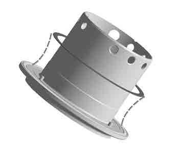
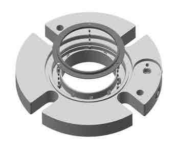
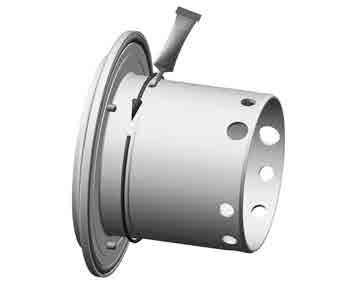
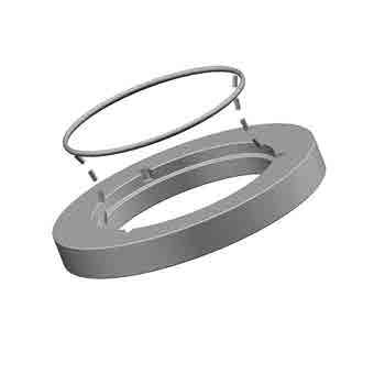
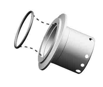
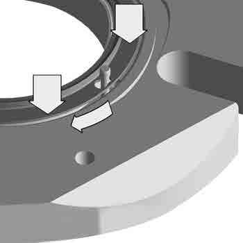
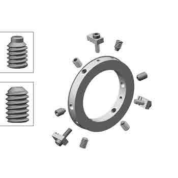
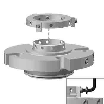
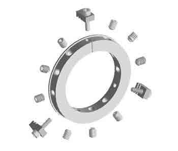
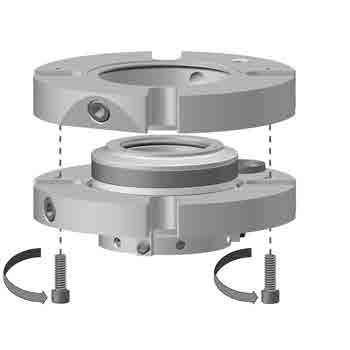
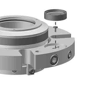
9 9.0 SEAL MAINTENANCE AND REUILD cont H TwinHybrid Gas Seal Rebuild Instructions 2 2a M a

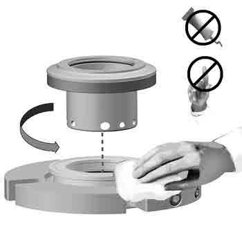
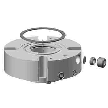
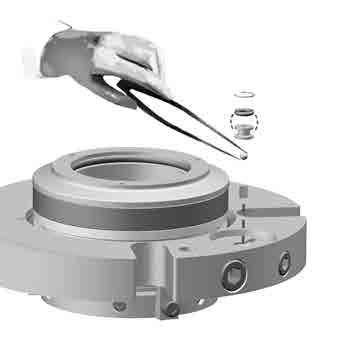
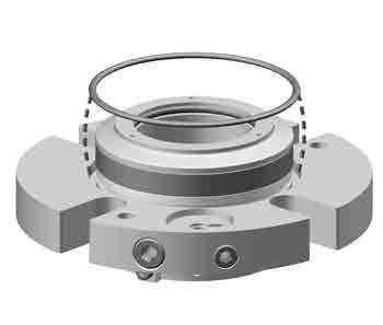
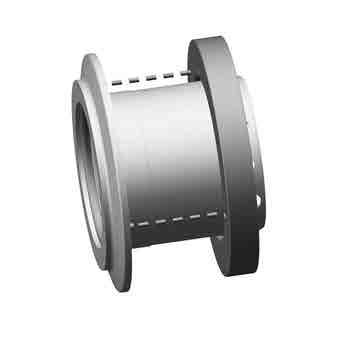
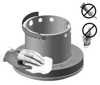
10 9.0 SEAL MAINTENANCE AND REUILD cont H TwinHybrid Gas Seal Rebuild Instructions (cont.) M a F M


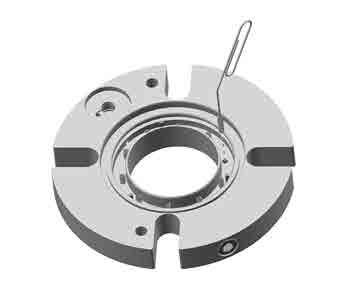
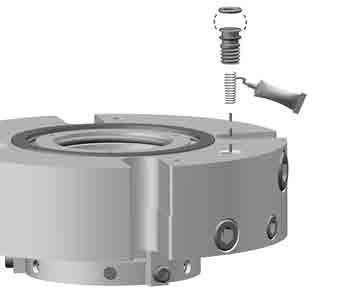
11 9.0 SEAL MAINTENANCE AND REUILD cont H TwinHybrid Gas Seal Rebuild Instructions (cont.) psi 1.4 bar psi 2-7 bar M
12 DISTRIUTED Y: Chesterton ISO certificates available on Salem Street Groveland, MA USA Telephone: Fax: A.W.Chesterton Company. Registered trademark owned and licensed by A.W.Chesterton Company in USA and other countries. FORM NO REV 4 3/16
4400 TwinHybrid Gas Seal
 4400 TwinHybrid Gas Seal EQUIPMENT PREPARATION MECHANICAL SEAL INSTALLATION INSTRUCTIONS 1 2 200.005" 0,13 mm 125 µ" 3,2 µm R a 3 4 32 µ" 0,8 µm R a 1000 ±.002" 0,05mm CAUTIONS These instructions are general
Installation Instructions
 Installation Instructions Durametallic SLM-6000, SLM-6100 Self contained cartridge medium duty slurry seal Experience In Motion 1 Cartridge Installation Instructions The following instruction manual is
John Crane Type 609HTC/ECS (High-Temperature Corrosion Resistant) Sealol Metal Bellows Seal Installation Instructions
 Sealol Metal Bellows Seal Installation Instructions") I-609HTC/ECS John Crane Type 609HTC/ECS (High-Temperature Corrosion Resistant) Sealol Metal ellows Seal Installation Instructions Foreword These instructions are provided to familiarize the user with the
I-609HTC/ECS John Crane Type 609HTC/ECS (High-Temperature Corrosion Resistant) Sealol Metal ellows Seal Installation Instructions Foreword These instructions are provided to familiarize the user with the
Installation, Operation and Maintenance Manual for Back Pressure Regulator
 Installation, Operation and Maintenance Manual for Back Pressure Regulator Model 8860 2009 Groth Corporation IOM-8860 Rev. B 12541 Ref. ID: 95565 Page 2 of 13 Table of Contents I. INTRODUCTION 3 II. DESIGN
INSTALLATION, OPERATION & MAINTENANCE GUIDE
 INSTALLATION, OPERATION & MAINTENANCE GUIDE INTERNATIONAL BRAZIL SOUTHERN USA HEADQUARTERS REPAIR & SERVICE 1 Jackson Street Rua Javaés, 441/443 1719 South Sonny Avenue Essex Junction, VT 05452 Bom Retiro,
TBV OPERATION AND MAINTENANCE MANUAL SERIES 2800: FLANGED BALL VALVE. For technical questions, please contact the following:
 TBV OPERATION AND MAINTENANCE MANUAL SERIES 2800: FLANGED BALL VALVE For technical questions, please contact the following: Engineering Department 1537 Grafton Road Millbury, MA 01527 Phone: (508) 887-9400
Welker Sampler. Model GSS-1. Installation, Operation, and Maintenance Manual
 Installation, Operation, and Maintenance Manual Welker Sampler Model GSS-1 The information in this manual has been carefully checked for accuracy and is intended to be used as a guide to operations. Correct
RD(H)20/25 Pressure-Reducing Regulator User Manual
20/25 Pressure-Reducing Regulator User Manual") RD(H)20/25 Pressure-Reducing Regulator User Manual Read the complete manual before installing and using the regulator. 2 Safe Product Selection When selecting a product, the total system design must be
RD(H)20/25 Pressure-Reducing Regulator User Manual Read the complete manual before installing and using the regulator. 2 Safe Product Selection When selecting a product, the total system design must be
Bulletin /06/2012 Supersedes 10/23/00. Installation of John Crane Type 73 Inflatable Mechanical Seal. Page 01 of 10
 01 of 10 1. Carefully read all instructions and notes before installation. 2. Bench Pre-assembly: a. Insert the support ring (item #1) inside the inflatable boot (item #2) to form inflatable seal assembly
Installation Instructions
 Installation Instructions BW Seals Uniseal Series Cartridge metal bellows single and dual seals Experience In Motion Description The Uniseal metal bellows seal series consists of: Uniseal I - Single seals
INSTALLATION, OPERATION AND MAINTENANCE GUIDE
 INSTALLATION, OPERATION AND Placement in Pipeline System When installing Process Development & Control s ElastoTITE Elastomer-Hinged Check Valves in a pipeline, a minimum of five pipe diameters should
LRS(H)4 Pressure-Reducing Regulator User Manual
4 Pressure-Reducing Regulator User Manual") LRS(H)4 Pressure-Reducing Regulator User Manual Read the complete manual before installing and using the regulator. 2 Safe Product Selection When selecting a product, the total system design must be considered
LRS(H)4 Pressure-Reducing Regulator User Manual Read the complete manual before installing and using the regulator. 2 Safe Product Selection When selecting a product, the total system design must be considered
WHEATLEY WHEATLEY SERIES 500 SWING CHECK VALVE. Installation, Operation and Maintenance Manual
 WHEATLEY SERIES 500 SWING CHECK VALVE STANDARD INTEGRAL SEAT & OPTIONAL REMOVABLE SEAT 2" FP - 6" FP 150# - 1500# 8" FP - 12" FP 150# - 900# API 6D and B16.34 2" FP - 4" FP 5000# DRILLING PRODUCTION VALVE
Installation Instructions
 Installation Instructions TM Five Star Seal 80 Series Dual, Cartridge Mounted, Flexible Stator Pusher Seal Designed for General Service Applications 86 and 87 Experience In Motion Description The 86/87
Pressure Dump Valve Service Kit for Series 2300 Units
 Instruction Sheet Pressure Dump Valve Service Kit for Series 00 Units. Overview The Nordson pressure dump valve is used to relieve hydraulic pressure instantly in Series 00 applicator tanks when the unit
Wafer Check Valve. Contents. User s Manual. (1) Be sure to read the following description of our product warranty 1
 Be sure to read the following description of our product warranty 1") Serial No. H-V066-E-3 Wafer Check Valve User s Manual Contents (1) Be sure to read the following description of our product warranty 1 (2) General operating instructions 2 (3) General instructions for
Serial No. H-V066-E-3 Wafer Check Valve User s Manual Contents (1) Be sure to read the following description of our product warranty 1 (2) General operating instructions 2 (3) General instructions for
RS(H)10,15 USER MANUAL. Read the complete manual before installing and using the regulator.
10,15 USER MANUAL. Read the complete manual before installing and using the regulator.") RS(H)10,15 USER MANUAL Read the complete manual before installing and using the regulator. WARNING INCORRECT OR IMPROPER USE OF THIS PRODUCT CAN CAUSE SERIOUS PERSONAL INJURY AND PROPERTY DAMAGE. Due to
RS(H)10,15 USER MANUAL Read the complete manual before installing and using the regulator. WARNING INCORRECT OR IMPROPER USE OF THIS PRODUCT CAN CAUSE SERIOUS PERSONAL INJURY AND PROPERTY DAMAGE. Due to
WHEATLEY Series 500 Swing Check Valve
 Document Number: TC003001-13 Revision: 02 WHEATLEY Series 500 Swing Check Valve Installation, Operation, and Maintenance Manual TABLE OF CONTENTS BILL OF MATERIALS...3 SCOPE...5 INSTALLATION AND OPERATION
KTM OM-2 SPLIT BODY FLOATING BALL VALVES INSTALLATION AND MAINTENANCE INSTRUCTIONS
 Before installation these instructions must be fully read and understood SECTION 1 - STORAGE 1.1 Preparation and preservation for storage All valves should be properly packed in order to protect the parts
PRS(TC)4,8 USER MANUAL. Read the complete manual before installing and using the regulator.
4,8 USER MANUAL. Read the complete manual before installing and using the regulator.") PRS(TC)4,8 USER MANUAL Read the complete manual before installing and using the regulator. WARNING INCORRECT OR IMPROPER USE OF THIS PRODUCT CAN CAUSE SERIOUS PERSONAL INJURY AND PROPERTY DAMAGE. Due to
PRS(TC)4,8 USER MANUAL Read the complete manual before installing and using the regulator. WARNING INCORRECT OR IMPROPER USE OF THIS PRODUCT CAN CAUSE SERIOUS PERSONAL INJURY AND PROPERTY DAMAGE. Due to
TYPE 3710 CARTRIDGE SPLIT SEAL Technical Specification
 A Mating Ring B Mating Ring/ Retaining Ring C Mating Ring/ Clamp Ring D Mating Ring Adapter E Primary Ring F Primary Ring/ Retaining Ring G Finger Springs H Spring Retainer I Gland O-ring J Flat Gasket
MUELLER. Mega-Lite Drilling Machine. Reliable Connections. table of contents PAGE. Equipment 2. Operating Instructions 3-4. Parts Information 5
 operating Instructions manual MUELLER Mega-Lite Drilling Machine table of contents PAGE Equipment 2 Operating Instructions 3-4 Parts Information 5 Travel Charts 6-11! WARNING: 1. Read and follow instructions
Installation, Operation, and Maintenance Manual
 Installation, Operation, and Maintenance Manual Welker Probe Instrument Regulator Model The information in this manual has been carefully checked for accuracy and is intended to be used as a guide for
Bray/ VAAS O-Ported Series Knife Gate Valve 770/780 Series Operation and Maintenance Manual
 Bray/ VAAS Knife Gate Valve 770/780 Series Operations and Maintenance Manual Table of Contents Definition of Terms 1 Safety Instructions 1 Introduction 2 Unpacking 2 Storage 2 Installation 2 Commissioning
Operation Manual Piston Sensed Gas Pressure Regulators
 687 Technology Way Napa, CA 94558 Phone: (707) 259-0102 FAX: (707) 259-0117 www.aptech-online.com Operation Manual Piston Sensed Gas Pressure Regulators (Models KT9, KT10, Welded KT10, KT12) Table of Contents:
UTEX INDUSTRIES, INC.
 UTEX INDUSTRIES, INC. C A R T R I D G E S E A L Externally located springs are virtually non-clogging Visible drive disc indicates face wear Setting clip removal unnecessary saving installation time Single-piece
Constant Pressure Crude Oil Container Model CPCCP
 Installation, Operations, and Maintenance Manual Constant Pressure Crude Oil Container Model CPCCP The information in this manual has been carefully checked for accuracy and is intended to be used as a
HAYWARD FLOW CONTROL Series PBV Back Pressure Valve and Series RPV Pressure Relief Valve INSTALLATION, OPERATION, AND MAINTENANCE INSTRUCTIONS
 HAYWARD FLOW CONTROL Series PBV Back Pressure Valve and Series RPV Pressure Relief Valve INSTALLATION, OPERATION, AND MAINTENANCE INSTRUCTIONS Page 1 of 20 Page 2 of 20 TABLE OF CONTENTS Safety Warnings
Float Operated Level Controllers
 CONTENTS Float Operated Level Controllers IM0015 Nov. 2014 PAGE Introduction 1 Scope 1 Description 1 Specification 1 Control Installation 2 INTRODUCTION Side Mount Back Mount Prior to installing, the instructions
TECHNICAL DATA CAUTION
 Page 1 of 6 1. DESCRIPTION The Viking Model D-2 Accelerator is a quick-opening device, with an integral anti-flood assembly, used to increase the operating speed of a differential type dry pipe valve.
Anderson Greenwood Series 93 Positive Pressure POSRV Installation and Maintenance Instructions
 Before installation these instructions must be fully read and understood Installation and maintenance instructions for Series 93 Positive Pressure Pilot Operated Safety Relief Valves (POSRV). The intent
Installation Instructions
 Installation Instructions Durametallic MD-200 Series Gas Dual Cartridge Canister Seal for Mixers and Agitators Experience In Motion 1 Equipment Check 1.1 Follow plant safety regulations prior to equipment
1.0 - OPENING AND CLOSING THE DOOR
 The purpose of this manual is to provide the user with instructions on how to safely open and close, how to conduct routine maintenance, and how to install the PEI TWINLOCK Closure on a pressure vessel.
Engineering Data Sheet
 Page 1 of 6 CE MARKING AND THE PRESSURE EQUIPMENT DIRECTIVE 97/23/EC Valves must be installed into a well designed system and it is recommended that the system be inspected in accordance with the appropriate
Installation Instructions
 Durametallic SL-5000 and SL-5200 Seals Cartridge Slurry Seals Installation Instructions Experience In Motion SL-5000 and SL-5200 Cartridge Seals are complete preset seal assemblies which include the sleeve
Pressure Dump Valve Service Kit for Series 3000 Units
 Instruction Sheet Pressure Dump Valve Service Kit for Series 000 Units. Overview The Nordson pressure dump valve is used to relieve hydraulic pressure instantly in Series 00, 400, 500, and 700 applicator
MUELLER. A Wall Type. Indicator Post. Reliable Connections. General Information 2. Technical Data/ Dimensions 3. Installation 4-5.
 Installation Instructions manual MUELLER table of contents PAGE A-20814 Wall Type General Information 2 Technical Data/ Dimensions Installation 4-5 Maintenance 6 Parts 7 Indicator Post! WARNING: 1. Read
1700ESL Kamvalok Coupler
 PART #H32138PA November 2008 1700ESL Kamvalok Coupler OPW Transport Series Dry Disconnect Couplings are considered the standard of the industry. For use on multi-compartment petroleum, solvent and chemical
AIR-OPERATED DOUBLE DIAPHRAGM PUMP USER S MANUAL
 00, 0, 000 00, 000, 00 A. TECHNICAL INFORMATION Model 00 Inlet/Outlet " Air Inlet /" 0 / 000 /" /" 00 /" /" 000 /" /" 00 /" /" Flow Rate GPM/ 0LPM GPM/ 0LPM GPM/ LPM GPM/ LPM GPM/ 0LPM GPM/ 0LPM Maximum
DelVal Flow Controls Private limited
 DelVal Flow Controls Private limited (A DIVISION OF DelTech CONTROLS LLC, USA) DelVal Series 50/5, 5A/5B Butterfly Valves INSTALLATION, OPERATION AND MAINTENANCE MANUAL ENGINEERING DATA SHEET E.D.S. NO
Tank Blanketing Pressure Regulators RHPS Series
 www.swagelok.com Tank Blanketing Pressure Regulators RHPS Series Types: pressure reducing and vapor recovery 16L stainless steel construction 1/2, 1, and 2 in. end connections Working pressures up to 22
TECHNICAL DATA ANTI-FLOOD DEVICE MODEL B-1 1. DESCRIPTION
 Page 1 of 6 1. DESCRIPTION The Model B-1 Anti-flood Device is required when Viking accelerators are installed on dry systems according to Viking Model E-1 Accelerator Trim Charts. In the SET condition,
INSTALLATION, OPERATION, AND MAINTENANCE MANUAL WELKER RELIEF VALVE
 INSTALLATION, OPERATION, AND MAINTENANCE MANUAL WELKER RELIEF VALVE MODELS RV-1 RV-2 RV-2CP RV-3 DRAWING NUMBERS AD017A[ ] AD018A[ ] AD020A[ ] AD282BO MANUAL NUMBER IOM-033 REVISION Rev. E, 3/28/2016 TABLE
P5513. Users Manual. Pneumatic Comparison Test Pump. Test Equipment Depot Washington Street Melrose, MA TestEquipmentDepot.
 Test Equipment Depot - 800.517.8431-99 Washington Street Melrose, MA 02176 TestEquipmentDepot.com P5513 Pneumatic Comparison Test Pump Users Manual PN 3963372 November 2010 2010 Fluke Corporation. All
Anti-flood device Model B-1
 December 4, 2009 Dry Systems 123a 1. DESCRIPTION The Anti-flood Device is required when Viking accelerators are installed on dry systems according to Viking Model E-1 Accelerator Trim Charts. In the SET
Installation Instructions For Flat Seated Bolted Type RAH Series Disk Holders
 Installation Instructions For Flat Seated Bolted Type RAH Series Disk Holders RA Series Rupture Disks 1. WARNING a) Read the complete instructions before attempting to install the rupture disk and holder
Installation Instructions
 Installation Instructions ISC Series Innovative Standard Cartridge seal designed for ANSI and general purpose applications with maximum interchangeability between designs. Experience In Motion Description
THE BP-301 SERIES. Operating and Service Manual. Series includes all variants of BP-301 (LF 0.1Cv / MF 0.5Cv)
") THE BP-301 SERIES Operating and Service Manual Series includes all variants of BP-301 (LF 0.1Cv / MF 0.5Cv) Issue B October 2015 1 TABLE OF CONTENTS 1. Description... 3 2. Installation... 3 3. Operation...
THE BP-301 SERIES Operating and Service Manual Series includes all variants of BP-301 (LF 0.1Cv / MF 0.5Cv) Issue B October 2015 1 TABLE OF CONTENTS 1. Description... 3 2. Installation... 3 3. Operation...
LRS(H)4 USER MANUAL. Read the complete manual before installing and using the regulator.
4 USER MANUAL. Read the complete manual before installing and using the regulator.") LRS(H)4 USER MANUAL Read the complete manual before installing and using the regulator. WARNING INCORRECT OR IMPROPER USE OF THIS PRODUCT CAN CAUSE SERIOUS PERSONAL INJURY AND PROPERTY DAMAGE. Due to the
LRS(H)4 USER MANUAL Read the complete manual before installing and using the regulator. WARNING INCORRECT OR IMPROPER USE OF THIS PRODUCT CAN CAUSE SERIOUS PERSONAL INJURY AND PROPERTY DAMAGE. Due to the
WHEATLEY Series 822/820 Swing Check Valve
 Document Number: TC003001-12 Revision: 02 WHEATLEY Series 822/820 Swing Check Valve Installation, Operation, and Maintenance Manual TABLE OF CONTENTS BILL OF MATERIALS...3 SCOPE...4 INSTALLATION AND OPERATION
THE MF-400 SERIES. Operating and Service Manual. Series includes all variants of MF-400/401
 THE MF-400 SERIES Operating and Service Manual Series includes all variants of MF-400/401 Issue A October 2013 1 TABLE OF CONTENTS 1. Description... 3 2. Installation... 3 3. Operation... 4 4. Special
PROPORTIONING VALVE. Model 150 INSTRUCTION MANUAL. March 2017 IMS Company Stafford Road
 PROPORTIONING VALVE Model 150 INSTRUCTION MANUAL March 2017 IMS Company 10373 Stafford Road Telephone: (440) 543-1615 Fax: (440) 543-1069 Email: sales@imscompany.com 1 Introduction IMS Company reserves
1200B2 Series Service Regulators. Instruction Manual
 00B Series Service Regulators Instruction Manual 00B Series Service Regulators 0 Elster American Meter 00B Series Service Regulators General Information The 00B Series Service Regulators are available
Booster Pump PB4-60 Replacement Kits
 Booster Pump PB4-60 Replacement Kits FOR YOUR SAFETY - This product must be installed and serviced by a contractor who is licensed and qualified in pool equipment by the jurisdiction in which the product
VALVES & MEASUREMENT
 VALVES & MEASUREMENT TBV OPERATION AND MAINTENANCE MANUAL SERIES 1100: THREE PIECE BALL VALVE For technical questions, please contact the following: Engineering Department 1537 Grafton Road Millbury, MA
EASTERN ENERGY SERVICES PTE LTD. 60 Kaki Bukit Place #02-19 Eunos Tech Park Singapore, SG Singapore Telephone: Fax:
 2 Table Of Contents 1. Introduction 3 2. About this Manual 3 3. Contacting YZ Systems 3 4. Vessel Components 4 5. Specifications 5 6. Application 6 7. Theory of Operation 7 8. DuraSite Installation & Use
THE HF-300 SERIES. Operating and Service Manual. Series includes all variants of HF-300/301
 THE HF-300 SERIES Operating and Service Manual Series includes all variants of HF-300/301 Issue A July 2015 1 TABLE OF CONTENTS 1. Description... 3 2. Installation... 3 3. Operation... 4 3.1. Spring Loaded...
4 IN. BALL LAUNCHER Engine Mounted / PTO Driven
 4 IN. BALL LAUNCHER Engine Mounted / PTO Driven OPERATOR S PARTS and MAINTENANCE MANUAL 2006 EDITION BL-MAN-4EN Creation Revision date: 10MAR06 date: by: Ivon LeBlanc by: Table of Contents Table of Contents...
INSTALLATION COMMISSIONING, OPERATION & MAINTENANCE MANUAL
 WedgeRock RW Series Worm Gear Actuators INSTALLATION COMMISSIONING, OPERATION & MAINTENANCE MANUAL Revision 01 Date 4/3/17 Page 1 Table of Contents 1.0 INTRODUCTION... 4 1.1 PURPOSE... 4 1.2 AUDIENCE...
Torque Specifications
 SENR3130-10 Torque Specifications All Caterpillar Products S/N From the library of Barrington Diesel Club CONTENT General Information 01/07/2005 Introduction to Torque 01/07/2005 Torque-Turn 01/07/2005
Model VR6 System. Installation, Operation & Maintenance
 Model VR6 System Installation, Operation & Maintenance General: All Archer Instruments chlorination systems are carefully designed and tested for years of safe, accurate field service. All Archer Instruments
BSA6T and BSA64T Stainless Steel Bellows Sealed Stop Valves Installation and Maintenance Instructions
 1843950/3 IM-P184-03 ST Issue 3 BSA6T and BSA64T Stainless Steel Bellows Sealed Stop Valves Installation and Maintenance Instructions 1. General safety information 2. General product information 3. Installation
Maintenance and Repair. AirHawk II Air Mask. Second Stage Regulator. Order No.: /02 Prnt. Spec (I) MSAsafety.
 MSAsafety.") Maintenance and Repair Second Stage Regulator Order No.: 10104241/02 Prnt. Spec. 10000005389(I) MSAsafety.com WARNING! Read this manual carefully before servicing the device. The device will perform as
Maintenance and Repair Second Stage Regulator Order No.: 10104241/02 Prnt. Spec. 10000005389(I) MSAsafety.com WARNING! Read this manual carefully before servicing the device. The device will perform as
FLANGED TWO-PIECE BALL VALVES
 INTRODUCTION This instruction manual includes installation, operation, and maintenance information for FNW flanged split-body ball valves. This manual addresses lever operated ball valves only. Please
Anderson Greenwood Series 400 Diaphragm Pilot Operated Safety Relief Valves. Installation and Maintenance Instructions for
 Before installation these instructions must be fully read and understood The main valve uses the principle of pressurizing the top or large area of a differential area piston with line pressure to hold
Assembly Drawing: W-311B-A01, or as applicable Parts List: W-311B-A01-1, or as applicable Special Tools: , , &
 REDQ Regulators Model 411B Barstock Design Powreactor Dome Regulator OPERATION AND MAINTENANCE Contents Scope..............................1 Installation..........................1 General Description....................1
Installation Instructions, Pressure Regulator Series
 Installation Instructions, Pressure Regulator 20517 Series Manual Model: 20517, L20517 Air motor Operated: F20517, LF20517 Hydraulic Motor Operated: G20517, LG20517 1. GENERAL ------------------------------------------------------------------------------
Allspeeds Ltd. Royal Works, Atlas St Clayton le Moors Accrington Lancashire England BB5 5LW. Tel +44 (0)
") Allspeeds Ltd. Royal Works, Atlas St Clayton le Moors Accrington Lancashire England BB5 5LW Tel +44 (0)1254 615100 www.allspeeds.co.uk HP690A Intensifier Panel including the following versions: Model Intensification
Allspeeds Ltd. Royal Works, Atlas St Clayton le Moors Accrington Lancashire England BB5 5LW Tel +44 (0)1254 615100 www.allspeeds.co.uk HP690A Intensifier Panel including the following versions: Model Intensification
Halsey Taylor Owners Manual STOP!
 Halsey Taylor Owners Manual 4710 Freeze Resistant Floor Mounted Steel Fountain STOP! PLEASE READ THE FOLLOWING INFORMATION. ITALLATION ITRUCTIO FOR THE 4710FR FTN. WITH 97243C SINGLE VALVE CONTROL ASSEMBLY
BCV31 DN40 - Blowdown Control Valve
 4034850/5 IM-P403-71 AB Issue 5 BCV31 DN40 - Blowdown Control Valve Installation and Maintenance Instructions 1. Safety information 2. Application 3. Technical data 4. Operation 5. Installation 6. Flow
INSTRUCTION MANUAL Kobelco Eagle Marine Water Lubricated Stern Tube Seals
 INSTRUCTION MANUAL Kobelco Eagle Marine Water Lubricated Stern Tube Seals A. Description of Seal Assembly B. Installation C. Piping D. Testing for undocking E. Installation check seat F. Operation G. Sealing
Installation, Operation, and Maintenance Manual. Welker Constant Pressure Cylinder With Welker Magnetic Indicator (With Gravity Mixer) Model CP2GM-HP
 Model CP2GM-HP") Installation, Operation, and Maintenance Manual Welker Constant Pressure Cylinder With Welker Magnetic Indicator (With Gravity Mixer) Model The information in this manual has been carefully checked for
Installation, Operation, and Maintenance Manual Welker Constant Pressure Cylinder With Welker Magnetic Indicator (With Gravity Mixer) Model The information in this manual has been carefully checked for
OPERATING AND MAINTENANCE MANUAL
 Series 4300 Engineered Performance TABLE OF CONTENTS 0 INTRODUCTION 1 1 Scope 1 2 Description 1 3 Specifications 1 0 INSTALLATION 1 1 Mounting 1 2 Piping 1 1 Connecting Process Pressure 2 2 Vent Connections
Installation Instructions
 Installation Instructions High Temperature Metal Bellows Seals Cartridge seals with flexible graphite gaskets BXH, BXHH, BXRH, BRC, GTSP, GSDH Series 1 Equipment Check 1.1 Follow plant safety regulations
Model Series 62 Constant Differential Relay
 Siemens Industry, Inc. INSTALLATION AND SERVICE INSTRUCTION INTRODUCTION Model Series 62 Constant Differential Relay Rev 11 March 2011 Supersedes Rev 10 The Constant Differential Relay maintains a constant
1800C and 1800C-HC Series Service Regulators
 1800C and 1800C-HC Series Service Regulators Installation Instructions www.elster-americanmeter.com General Information: The 1800C and 1800C-HC Regulators are available as Full Capacity Internal Relief
Contents. Stainless Steel Side Block. 1.1 Separating the Side Block. Stainless Steel Side Block Reassembly of. Assembly from the Helmet Shell
 Separating the Side Block Assembly from the Helmet Shell Contents SSB-1 SSB-3 SSB-5 SSB-5 SSB-7 1.1 Separating the Side Block Assembly from the Helmet Shell 1.2 Side Block Assembly Replacement 1.3 Defogger
INSTALLATION. and INSTRUCTION MANUAL. for QUALITY AIR BREATHING SYSTEMS. Model 50 Systems Outfitted with ABM-725 Monitor C O M P A N Y
 INSTALLATION and INSTRUCTION MANUAL for QUALITY AIR BREATHING SYSTEMS Model 50 Systems Outfitted with ABM-725 Monitor M A R T E C H S E R V I C E S C O M P A N Y OFFICE: (507) 843-4700 P.O. BOX 7079 Toll
KBV21i and KBV40i Key Operated Boiler Blowdown Valves Installation and Maintenance Instructions
 4059051/3 IM-P405-48 EMM Issue 3 KBV21i and KBV40i Key Operated Boiler Blowdown Valves Installation and Maintenance Instructions 1. Safety information 2. General product information 3. Installation 4.
SHUR-LOK CORPORATION TECHNICAL SALES BULLETIN
 Page 1 of 9 1. SCOPE: 1.1. This provides the minimum design, port preparation and installation and removal requirements for SLAS4383-XX-XX, SLF2002-XX-XX and SLF3004-XX-XX adapter reducer and is applicable
MUELLER GAS. No-Blo Operations Using D-5. Drilling Machine. Reliable Connections. General Information 2
 operating Instructions manual MUELLER GAS TAble of contents PAGE No-Blo Operations Using D-5 General Information 2 Installing No-Blo Service Tees, Service Stop Tees and Curb Stop Tees 3-8 Reconditioning
Mounting and Operating Instructions EB EN. Type Supply Pressure Regulator. with increased air capacity
 Type 4708-45 Supply Pressure Regulator with increased air capacity Translation of original instructions Mounting and Operating Instructions EB 8546-1 EN Edition March 2016 Note on these mounting and operating
TriPod Safety Coupler Installation & Operating Instructions for Models TP4, TP5, TP6, and TP7
 TriPod Safety Coupler Installation & Operating Instructions for Models TP4, TP5, TP6, and TP7 March 2014 Form FVC097 - Rev03 IMPORTANT: KEEP THIS DOCUMENT WITH THE PRODUCT UNTIL IT REACHES THE END USER.
Installation, Operation, and Maintenance Manual. Welker Constant Pressure Cylinder With Solid Indicator (Non-mixer) Model CP-30SI
 Model CP-30SI") Installation, Operation, and Maintenance Manual Welker Constant Pressure Cylinder With Solid Indicator (Non-mixer) Model The information in this manual has been carefully checked for accuracy and is intended
Installation, Operation, and Maintenance Manual Welker Constant Pressure Cylinder With Solid Indicator (Non-mixer) Model The information in this manual has been carefully checked for accuracy and is intended
Type BBS-03, BBS-05, BBS-06, BBS-25
 Type BBS-03, BBS-05, BBS-06, BBS-25 Sterile connection elements Sterile Verbindungselemente Raccords union stériles Operating Instructions Bedienungsanleitung Manuel d utilisation 1. THE OPERATING INSTRUCTIONS
DS05C,D,G Dial Set Pressure Regulating Valves
 DS05C,D,G Dial Set Pressure Regulating Valves APPLICATION The Honeywell DS05C,D,G Dial Set Pressure Regulating Valve is a high quality pressure regulating valve that maintains a constant outlet pressure
Series SFD. Clean Air Filter. Variations. Made to Order. Type. Cartridge (replaceable element) Disposable (non-replaceable element) Up to 100
 Disposable (non-replaceable element) Up to 100") Clean Air Filter Variations SFD SFD SFD SFD Made to Order Type Disposable (non-replaceable element) Cartridge (replaceable element) Flow rate L/min (ANR) (at inlet pressure.7 MPa) Up to 6 Up to 8 Up to
Clean Air Filter Variations SFD SFD SFD SFD Made to Order Type Disposable (non-replaceable element) Cartridge (replaceable element) Flow rate L/min (ANR) (at inlet pressure.7 MPa) Up to 6 Up to 8 Up to
Type S301 & S302 Gas Regulators INTRODUCTION INSTALLATION. Scope of Manual. Description. Specifications. Type S301 and S302. Instruction Manual
 Fisher Controls Instruction Manual Type S301 & S302 Gas Regulators October 1981 Form 5180 WARNING Fisher regulators must be installed, operated, and maintained in accordance with federal, state, and local
INSTALLATION, OPERATION, AND MAINTENANCE MANUAL WELKER CONSTANT PRESSURE CYLINDER
 INSTALLATION, OPERATION, AND MAINTENANCE MANUAL WELKER CONSTANT PRESSURE CYLINDER MODEL CP-11 DRAWING NUMBERS AD157CO AD157CP.CE MANUAL NUMBER IOM-184 REVISION Rev. B, 6/7/2018 TABLE OF CONTENTS SAFETY
ROTATING DISK VALVES INSTALLATION AND MAINTENANCE 1. SCOPE 3 2. INFORMATION ON USAGE 3 3. VALVE TYPES 3 4. OPERATORS 5 5. VALVE CONSTRUCTION 6
 Sub Section INDEX Page Number 1. SCOPE 3 2. INFORMATION ON USAGE 3 3. VALVE TYPES 3 4. OPERATORS 5 5. VALVE CONSTRUCTION 6 6. INSTALLATION AND OPERATION 6 7. MAINTENANCE 8 8. REPAIR 9 9. ASSEMBLY 10 10.
INSTALLATION, MAINTENANCE & OPERATING INSTRUCTIONS 2-4 REDUCED PORT/ FULL PORT (5700/6700) ANSI CLASS 150/300/600/900/1500/2500 TRUNNION BALL VALVES
 ANSI CLASS 150/300/600/900/1500/2500 TRUNNION BALL VALVES") PBV-USA,Inc. 12735 Dairy Ashford. Stafford, Texas USA 77477 281-340-5400; 800-256-6193 FAX: 281-340-5499 INDUSTRIAL BALL VALVES IM0 69 April 2001 Rev 9 INSTALLATION, MAINTENANCE & OPERATING INSTRUCTIONS
PBV-USA,Inc. 12735 Dairy Ashford. Stafford, Texas USA 77477 281-340-5400; 800-256-6193 FAX: 281-340-5499 INDUSTRIAL BALL VALVES IM0 69 April 2001 Rev 9 INSTALLATION, MAINTENANCE & OPERATING INSTRUCTIONS
TYPE 2800E EXTERNALLY MOUNTED, GAS LUBRICATED, NON-CONTACTING, DOUBLE CARTRIDGE SEAL
 A Seat/Mating Ring B Face/Primary Ring (inboard) C Spring D Face/Primary Ring (outboard) E O-Ring F Drive Collar G Setting Ring H Sleeve TYPE 2800E B A D C H E Spiral Groove Technology G F Product Description
Type CT88 Backpressure Regulator
 Instruction Manual Type CT88 July 2016 Type CT88 Backpressure Regulator Table of Contents Introduction...1 Specifications...2 Principle of Operation...2 Installation...3 Overpressure Protection...4 Startup...4
ATD LB PRESSURE BLASTER INSTRUCTION MANUAL
 ATD-8402 90LB PRESSURE BLASTER INSTRUCTION MANUAL SAVE THESE INSTRUCTIONS SAFETY INSTRUCTIONS FOR SANDBLASTER 1. Before opening the tank release the air pressure on the sand tank. To do this, turn off
USM21 Sealed Bimetallic Steam Trap for use with Pipeline Connectors Installation and Maintenance Instructions
 6250250/1 IM-P625-03 ST Issue 1 USM21 Sealed Bimetallic Steam Trap for use with Pipeline Connectors Installation and Maintenance Instructions 1. General safety information 2. General product information
INSTALLATION INSTRUCTIONS. CVS 67CFR Pressure Reducing Instrument Supply Regulator INTRODUCTION
 INSTALLATION INSTRUCTIONS CVS 67CFR Pressure Reducing Instrument Supply Regulator INTRODUCTION The CVS Controls 67CFR Filter regulator is a pressure reducing supply regulator typically used for pneumatic
Mounting and Operating Instructions EB 8546 EN. Type 4708 Supply Pressure Regulators. Translation of original instructions. Type Type
 Type 4708 Supply Pressure Regulators Translation of original instructions Type 4708-53 Type 4708-64 Type 4708-12 Mounting and Operating Instructions Edition March 2018 Note on these mounting and operating
Manual Actuated Boiler Blowdown Valves
 Manual Actuated Boiler Blowdown Valves Installation and Maintenance Instructions 1. Safety information 2. General product information 3. Installation 4. Operation 5. Maintenance 6. Spare parts p.1 1. Safety
MAINTENANCE PROCEDURE FOR X 650
 MAINTENANCE PROCEDURE FOR X 650 X 650 25. juli 2005-1/6 MAINTENANCE PROCEDURE FOR X 650 2 ND STAGE WARNING: This maintenance procedure is only for appointed Scubapro technicians that completed a course
FLANGED TWO-PIECE BALL VALVES
 INTRODUCTION This instruction manual includes installation, operation, and maintenance information for FNW flanged split-body ball valves. This manual addresses lever operated ball valves only. Please