Model VR6 System. Installation, Operation & Maintenance
|
|
|
- Kathlyn Reynolds
- 6 years ago
- Views:
Transcription
1 Model VR6 System Installation, Operation & Maintenance General: All Archer Instruments chlorination systems are carefully designed and tested for years of safe, accurate field service. All Archer Instruments chlorination systems are carefully tested prior to shipment. All Archer Instruments products are made of the finest materials. To ensure best operation, read these instructions carefully and completely and store them where all maintenance personnel will have access to them. Safety: When working with chlorine, always use caution and follow applicable safety procedures. General safety considerations: * Store chlorine separately from ammonia. * When using chlorine, avoid locations that expose the cylinder and equipment to direct sunlight. * Do not apply heater or heat source directly to chlorine cylinders. * 150lb (upright) cylinders: Always keep cylinders upright and ensure the steel valve cap is in place when moving cylinders. Once cylinder is in place, a safety chain should be used to secure the cylinder. * Ton Containers: Use appropriate handling equipment when moving ton containers. When readying ton container for use, ensure valves are aligned vertically. The top valve accesses gaseous chlorine and the bottom valve accesses liquid chlorine. The bottom valve should never be touched unless your system employs a chlorine heat exchanger (evaporator) designed expressly for use with liquid chlorine. When drawing gas from ton containers an appropriate ton container adapter and drip leg must be used (also available from Archer).
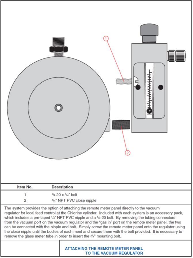
2 Installing the VR6 Vacuum Regulator: 1) Carefully inspect the cylinder valve outlet surfaces and vacuum regulator inlet capsule surfaces for damage or debris prior to installation. 2) Note that the inlet port on the VR6 regulator ships with a filter cartridge installed. Do not remove this filter, as doing so will bring on maintenance requirements. 3) Always use a new lead gasket when connecting the vacuum regulator to a chlorine cylinder valve. 4) Holding the vacuum regulator upright, settle it over the cylinder valve and fit the inlet capsule into the cylinder valve outlet port. 5) Using a 3/8 wrench, tighten the yoke assembly half-dog set screw so that the lead gasket is crushed between the valve and the inlet capsule. 6) Connect the vent and vacuum tubing to the regulator (these are labeled). See Figure 1. NOTE: Vent tubing should always be connected and run to a safe location (outside of any building). A vent bug cap (provided with every Archer vacuum regulator) should be fitted over the end of vent tubing to prevent insects from entering the equipment. Installing the Remote Meter: 1) The remote meter panel is typically installed on a wall or panel using the two pre-drilled mounting holes found on the meter body. However, the VR6 design allows for mounting the remote meter directly to the VR6 vacuum regulator, using the ¼ pipe nipple and mounting screw, which are include in your accessory pack. 2) The remote meter panel must be installed in the system between the vacuum source (ejector) and the gas source (chlorine cylinder / vacuum regulator). Refer to Figure 1. 3) Note that the gas flows up through the remote meter panel, and from the chlorine cylinder to the ejector. The top tubing connector is connected to the ejector (vacuum source) and the bottom tubing connector to the vacuum regulator. 4) Once the remote meter panel is mounted and the tubing connected, it can be used to perform a quick check on the system for vacuum leaks. By operating the ejector with the chlorine cylinder valve(s) shut, the ball in the remote meter panel should settle at the bottom and not move. If the ball continues to float or if it continually bounces, a vacuum leak is indicated in the system.
3 Operating the VR6 Vacuum Regulator: 1) Prior to placing the vacuum regulator into operation, it is important to carefully test the lead gasket seal. A small squeeze bottle (provided with every Archer vacuum regulator) should be partially filled with ammonia. Squeezing the bottle allows the ammonia fumes to be used to test for chlorine leaks. A leak is detected by a visible light gray / white gas cloud when the two fumes interact. To test for leaks, open the cylinder valve 1/3 turn and then close immediately. This pressurizes the lead gasket seal but ensures the full cylinder of chlorine is isolated during leak testing. Use ammonia fumes around the cylinder valve and lead gasket to check for any signs of leaking gas. If a leak is found, this must be addressed before placing the unit into operation. 2) After confirming no leaks exist, open the chlorine cylinder valve 1/3 of a turn. This is fully open and there is no need to open the valve further. 3) If the remote meter is not mounted on the VR6, no further action is needed. 4) If the remote meter is installed on the VR6, adjust the remote meter s rate valve knob until the desired feed rate is indicated on the graduated meter tube.
4 Operating the Remote Meter: 1) Once installed and connected, the remote meter panel is placed into operation by opening the cylinder valves and operating the ejector. 2) Turn the rate control knob until the desired feed rate is indicated. NOTE: The rate control valve is not designed to be used as a shut-off valve. To shut off gas feed, shut off motive water to the ejector. Maintaining the VR6: Recommended Maintenance Frequency: Archer recommends yearly routine maintenance. -Refer to the parts diagram when performing maintenance on the VR6. 1) To disassemble, remove the two yoke screws and pull the metal yoke & inlet assembly out of the back of the vacuum regulator. 2) Remove the four body screws and separate the front and back bodies. The diaphragm assembly can then be removed by carefully pulling it straight out of the front body. Take care to not lose the vent spring, which is located between the diaphragm assembly and the front body. 3) The guide pin is threaded into the rear diaphragm plate and should not need to be removed during routine maintenance. 4) The rear diaphragm plate and front diaphragm plate are threaded together and can often be unscrewed by hand. If they will not unscrew by hand, it may be necessary to use a vice and / or channel locks. Unscrewing these two parts allows for the removal of the diaphragm. 5) Whenever routine maintenance is being performed, all parts should be thoroughly cleaned. It is recommended that all o-rings (with the exception of the OA-VIT-332) be replaced. 6) When reassembling, new o-rings should be given a thin film of the Fluorolube grease. NEXT: The inlet assembly is a critical component in the safe function of the vacuum regulator. Improper handling or reassembly can result in dangerous leakage of chlorine gas. Archer recommends that only trained personnel or those familiar with vacuum regulator maintenance service the inlet assembly.
5 To service the inlet assembly: 1. Remove the two screws holding the metal yoke plate to the vacuum regulator body. 2. Grasp the metal yoke and with a slight turning motion pull it out of the back body. 3. Remove the OA-VIT-214 O-Ring from the Seal Plug. 4. Remove the Inlet Filter Holder (and/or the filter) from the Seal Adapter. 5. Using a short flat head screwdriver and a pair of pliers unscrew the YMA-100A Inlet Valve Stem from the VRA-601A Spring Retainer. NOTE: Protect the VRA-601A Spring Retainer from the pliers with a cloth or paper. NOTE: This should be done with the Seal Plug installed in the Yoke Assembly unless the Yoke Assembly is being replaced. 6. Now the VRA-601A, YMA-100A and SPA-104 should be removed and cleaned. NOTE: Especially clean the YMA-100A in the region where it meets the YPA-101A to form the seal. This surface should be polished as smooth as possible without scratching the surface. 7. Using a rod of 0.250" diameter, the YPA-101A Inlet Valve Seat can be pressed out of the Seal Plug from the spring side. The YPA-101A should be cleaned and carefully inspected for scratches or cuts especially where it is to seal with the YMA-100A. NOTE: Sometimes the YPA-101A will be cut or deformed such that it cannot seal. If you perform this service and the Vacuum Regulator is still leaking to vent, then the YPA-101A should be replaced with a new one. 8. Clean the Seal Plug thoroughly before reassembling the unit in the following order: a. Lubricate O-Rings with Fluorolube grease. b. Insert the new or cleaned YPA-101A with O-Ring OA-VIT-010. c. Insert and retighten the YMA-100A, VRA-601A and SPA-104 as shown in the drawing. NOTE: DO NOT USE EXCESSIVE FORCE IN TIGHTENING the YMA-100A to the VRA-601A. d. Insert a new Filter Cartridge. e. Install a new OA-VIT-214 O-Ring on the Seal Plug. -Should you have any questions during maintenance of your vacuum regulator, please contact your local service provider or Archer for support.
6 Maintaining the Remote Meter: 1. Unscrew the rate valve knob and stem (by hand) completely out of the rate valve bonnet. NOTE: Be careful not to let the meter tube drop in the next step. It will come loose. 2. Unscrew the rate valve bonnet using pliers (carefully and using a cloth to protect the part). The rate valve sleeve should also be removed. 3. Replace the OA-VIT-008 O-Rings on the rate valve stem by separating the valve bonnet and sleeve. 4. Lubricate the new O-Rings lightly with Fluorolube grease before replacing the sleeve, bonnet and rate valve. Cleaning The Glass Meter Tube: 1. Remember to be careful not to lose the stops or ball in the following steps. 2. Remove the white stops at either end of the tube (you could use a paper clip). 3. Soak the tube in warm water with a cleaner like Lime-Away or muriatic acid. Also, brush the inside of the tube with a pipe cleaner. NOTE: Always follow safety precautions with muriatic acid and other chemicals. 4. Dry the meter tube and reinstall the ball and stops. 5. It is recommended that new meter tube gaskets be used when reinstalling the tube. 6. Reinstall the meter gaskets and meter tube, making sure to center the tube on the top and bottom meter gaskets. 7. Tighten the rate valve bonnet with reasonable force to make a seal. Do not use excessive force.
7

8 Item# Qty. Part # Description Item# Qty. Part # Description 1 1 OA-VIT-014 O-Ring * 14 1 KFA-300 Filter Holder 2 1 VRA-104 Pin guide 15 1 VRA-5015 Filter * 3 1 VRA-600 Guide Pin 16 1 YMA-100A Inlet Valve 4 1 OA-VIT-006 O-Ring * 17 1 YPA-101A Inlet Valve Seat * 5 1 DPA-103 Double Diaphragm * 18 1 OA-VIT-010 O-Ring * 6 1 FBA-600 Front Body 19 1 SPA-104 Inlet Spring 7 1 OA-VIT-156 O-Ring 20 1 VRA-601A Spring Retainer 8 1 BBA-600 Back Body 21 1 OA-VIT-009 O-Ring * 9 1 OA-VIT-332 O-Ring 22 1 VRA-56A Rear Diaphragm Plate 10 4 BTA-123 Body Screws (Monel) 23 1 OA-VIT-029 O-Ring * 11 1 OA-VIT-214 O-Ring * 24 1 VRA-269 Front Diaphragm Plate 12 1 YMA-605A Back Plate 25 1 SPA-100 Vent Spring 13 1 SAWS-US3 Seal Adapter 26 2 TCA-64 ¼ NPT x 3/8 tube connector * Notes: * - These parts are included in the Parts - Maintenance Kit KT6-10C Date: Feb 2016 Drawing: VR6

9 Item# Qty. Part # Description Item# Qty. Part # Description 1 1 RVA-402 Knob 6 1 MTA-108-XXX Meter Tube 004 / 010 / 025 / 050 / 100 = PPD 2 1 RVA-349 Rate Valve Bonnet 7 2 MGA-X Meter Gasket 1 / 2 / 3 10, 25, 100 PPD 3 1 MPA-447 Meter Body 8 2 OA-VIT-112 O-Ring 4 2 TCA-64 Tubing Connector 9 2 OA-VIT-008 O-Ring 5 1 RVA-351 Sleeve 25 PPD & below 10 1 RVA-418 Stem 25 PPD & below or RVA-350 Sleeve 50 & 100 PPD or RVA-665 Stem 50 & 100 PPD Notes: Vacuum Tube Connector supplied for 3/8 tubing. Tap size is ¼ NPT. Date: Feb 2016 Drawing Number: MPA-6
Gas Chlorination Systems Series E5000 Up to 100ppd Instruction Manual
 Gas Chlorination Systems Series E5000 Up to 100ppd Instruction Manual All ENCHLOR Chlorination systems are carefully designed and tested for years of safe, accurate field service. All ENCHLOR Chlorination
HGC-200 Hydro Gas Chlorinator
 HGC-200 Hydro Gas Chlorinator ProMinent Fluid Controls Pty Ltd Head Office: Unit 4, 4 Narabang Way BELROSE NSW 2085 AUSTRALIA (PO Box 85, BELROSE WEST NSW 2085) Phone: (02) 9450 0995 Fax: (02) 9450 0996
ACV-10 Automatic Control Valve
 ACV-10 Automatic Control Valve Installation, Operation & Maintenance General: The Archer Instruments ACV-10 is a precision automatic feed rate control valve for use in vacuum systems feeding Chlorine,
Automatic Switchover Gas Chlorination Systems Series 900
 Automatic Switchover Gas Chlorination Systems Series 900 Instruction Manual All Hydro Instruments Chlorination systems are carefully designed and tested for years of safe, accurate field service. All Hydro
Instruction Manual ADVANCE Series 480 Vacuum Regulator
 Instruction Manual ADVANCE Series 480 Vacuum Regulator 80 60 40 20 R - 1-100.6001.15 These instructions describe the installation, operation and maintenance of the subject equipment. Failure to strictly
Instruction Manual Series 200 ADVANCE Cylinder or Ton Container Mounted Vacuum Regulators
 Instruction Manual Series 200 ADVANCE Cylinder or Ton Container Mounted Vacuum Regulators 100 & 250 PPD (2 & 5 kg/h) Cylinder Mounted 500 PPD (10 kg/h) Cylinder Mounted 500 PPD (10 kg/h) Ton Container
Chemical Injection Technologies Installation/Service Bulletin
 Bulletin 4002 Chemical Injection Technologies Installation/Service Bulletin SUPERIOR Series CL-16/26/56 Automatic Switchover Gas Chlorinator - Installation & Operation IMPORTANT!! READ THESE PRECAUTIONS
RG1200 Service and Repair Manual
 Dive Rite RG 1200 Regulator Service and Repair Manual Page 1 Text and Photography by Pete Nawrocky Copyright ( ) 1999-2000, Lamartek, Inc., dba Dive Rite RG1200 Service and Repair Manual First Stage.........................................
Welker Sampler. Model GSS-1. Installation, Operation, and Maintenance Manual
 Installation, Operation, and Maintenance Manual Welker Sampler Model GSS-1 The information in this manual has been carefully checked for accuracy and is intended to be used as a guide to operations. Correct
Installation, Operation, and Maintenance Manual
 Installation, Operation, and Maintenance Manual Welker The information in this manual has been carefully checked for accuracy and is intended to be used as a guide for the installation, operation, and
Installation, Operation, and Maintenance Manual
 Installation, Operation, and Maintenance Manual Welker Probe Instrument Regulator Model The information in this manual has been carefully checked for accuracy and is intended to be used as a guide for
Instruction Manual - Diaframless TM Ejector Chlorine, Sulfur Dioxide and Ammonia
 Instruction Manual - Diaframless TM Ejector Chlorine, Sulfur Dioxide and Ammonia - 1-122.6010.6 These instructions describe the installation, operation and maintenance of the subject equipment. Failure
RHPS Series RD(H)F40 User Manual. Read the complete manual before installing and using the regulator.
F40 User Manual. Read the complete manual before installing and using the regulator.") RHPS Series RD(H)F40 User Manual Read the complete manual before installing and using the regulator. 2 WARNING Before removing a regulator from the system for service, you must depressurize system purge
RHPS Series RD(H)F40 User Manual Read the complete manual before installing and using the regulator. 2 WARNING Before removing a regulator from the system for service, you must depressurize system purge
MEGR-1912 Instruction Manual
 MEGR-1912 PRESSURE REGULATOR Instruction Manual- Look Inside For: Description Installation Start-Up Maintenance Parts Ordering Parts List Marshall Excelsior Company Marshall, MI 49068 269-789-6700 FAX
RS(H)10,15 USER MANUAL. Read the complete manual before installing and using the regulator.
10,15 USER MANUAL. Read the complete manual before installing and using the regulator.") RS(H)10,15 USER MANUAL Read the complete manual before installing and using the regulator. WARNING INCORRECT OR IMPROPER USE OF THIS PRODUCT CAN CAUSE SERIOUS PERSONAL INJURY AND PROPERTY DAMAGE. Due to
RS(H)10,15 USER MANUAL Read the complete manual before installing and using the regulator. WARNING INCORRECT OR IMPROPER USE OF THIS PRODUCT CAN CAUSE SERIOUS PERSONAL INJURY AND PROPERTY DAMAGE. Due to
LRS(H)4 USER MANUAL. Read the complete manual before installing and using the regulator.
4 USER MANUAL. Read the complete manual before installing and using the regulator.") LRS(H)4 USER MANUAL Read the complete manual before installing and using the regulator. WARNING INCORRECT OR IMPROPER USE OF THIS PRODUCT CAN CAUSE SERIOUS PERSONAL INJURY AND PROPERTY DAMAGE. Due to the
LRS(H)4 USER MANUAL Read the complete manual before installing and using the regulator. WARNING INCORRECT OR IMPROPER USE OF THIS PRODUCT CAN CAUSE SERIOUS PERSONAL INJURY AND PROPERTY DAMAGE. Due to the
INSTALLATION INSTRUCTIONS 1/2 THERMOSTATIC VALVE AND TRIM
 INSTALLATION INSTRUCTIONS 1/2 THERMOSTATIC VALVE AND TRIM Valve Model No's: 1-741, 1-742, 1-743, 1-744 1-741 1-742 1-743 1-744 2001 CARNEGIE AVE, SANTA ANA CA 92705 (949) 417-5207 WWW.NEWPORTBRASS.COM
INSTALLATION, OPERATION, AND MAINTENANCE MANUAL WELKER RELIEF VALVE
 INSTALLATION, OPERATION, AND MAINTENANCE MANUAL WELKER RELIEF VALVE MODELS RV-1 RV-2 RV-2CP RV-3 DRAWING NUMBERS AD017A[ ] AD018A[ ] AD020A[ ] AD282BO MANUAL NUMBER IOM-033 REVISION Rev. E, 3/28/2016 TABLE
LRS(H)4 Pressure-Reducing Regulator User Manual
4 Pressure-Reducing Regulator User Manual") LRS(H)4 Pressure-Reducing Regulator User Manual Read the complete manual before installing and using the regulator. 2 Safe Product Selection When selecting a product, the total system design must be considered
LRS(H)4 Pressure-Reducing Regulator User Manual Read the complete manual before installing and using the regulator. 2 Safe Product Selection When selecting a product, the total system design must be considered
PRS(TC)4,8 USER MANUAL. Read the complete manual before installing and using the regulator.
4,8 USER MANUAL. Read the complete manual before installing and using the regulator.") PRS(TC)4,8 USER MANUAL Read the complete manual before installing and using the regulator. WARNING INCORRECT OR IMPROPER USE OF THIS PRODUCT CAN CAUSE SERIOUS PERSONAL INJURY AND PROPERTY DAMAGE. Due to
PRS(TC)4,8 USER MANUAL Read the complete manual before installing and using the regulator. WARNING INCORRECT OR IMPROPER USE OF THIS PRODUCT CAN CAUSE SERIOUS PERSONAL INJURY AND PROPERTY DAMAGE. Due to
EASTERN ENERGY SERVICES PTE LTD. 60 Kaki Bukit Place #02-19 Eunos Tech Park Singapore, SG Singapore Telephone: Fax:
 2 Table Of Contents 1. Introduction 3 2. About this Manual 3 3. Contacting YZ Systems 3 4. Vessel Components 4 5. Specifications 5 6. Application 6 7. Theory of Operation 7 8. DuraSite Installation & Use
Installation, Operation and Maintenance Manual for Back Pressure Regulator
 Installation, Operation and Maintenance Manual for Back Pressure Regulator Model 8860 2009 Groth Corporation IOM-8860 Rev. B 12541 Ref. ID: 95565 Page 2 of 13 Table of Contents I. INTRODUCTION 3 II. DESIGN
Instruction Manual O-Ring Ejector Chlorine & Sulfur Dioxide to 500 PPD (10 kg/h)
") Instruction Manual O-Ring Ejector Chlorine & Sulfur Dioxide to 500 PPD (10 kg/h) 100 PPD (2 kg/h) Maximum 250 PPD (5 kg/h) Maximum 500 PPD (10 kg/h) Maximum - 1-122.6006.9 These instructions describe the
Instruction Manual O-Ring Ejector Chlorine & Sulfur Dioxide to 500 PPD (10 kg/h) 100 PPD (2 kg/h) Maximum 250 PPD (5 kg/h) Maximum 500 PPD (10 kg/h) Maximum - 1-122.6006.9 These instructions describe the
WHEATLEY WHEATLEY SERIES 500 SWING CHECK VALVE. Installation, Operation and Maintenance Manual
 WHEATLEY SERIES 500 SWING CHECK VALVE STANDARD INTEGRAL SEAT & OPTIONAL REMOVABLE SEAT 2" FP - 6" FP 150# - 1500# 8" FP - 12" FP 150# - 900# API 6D and B16.34 2" FP - 4" FP 5000# DRILLING PRODUCTION VALVE
Hydraulic Punch Drivers
 SERVICE MANUAL 7804SB / 7806SB Quick Draw 7704SB / 7706SB Quick Draw Flex Quick Draw Hydraulic Punch Drivers Serial Codes AHJ and YZ Read and understand all of the instructions and safety information in
Chlorinator. MODEL C-731 (Floor Mounted)
") Chlorinator MODEL C-731 (Floor Mounted) CHLOROTECH Model C-731 is the advance technology Chlorinator designed to feed chlorine gas at a controlled rate. The flow rate of gas is maintained by constant positive
Chlorinator MODEL C-731 (Floor Mounted) CHLOROTECH Model C-731 is the advance technology Chlorinator designed to feed chlorine gas at a controlled rate. The flow rate of gas is maintained by constant positive
Installation Instructions
 Installation Instructions S65-135 (Circular) S65-136 (Semi-Circular) Air Valve Retrofit For Non-Sectional Classic Washfountain Table of Contents.......................2-6 Metering Air Valve Parts List....................6
Contents. Stainless Steel Side Block. 1.1 Separating the Side Block. Stainless Steel Side Block Reassembly of. Assembly from the Helmet Shell
 Separating the Side Block Assembly from the Helmet Shell Contents SSB-1 SSB-3 SSB-5 SSB-5 SSB-7 1.1 Separating the Side Block Assembly from the Helmet Shell 1.2 Side Block Assembly Replacement 1.3 Defogger
TBV OPERATION AND MAINTENANCE MANUAL SERIES 2800: FLANGED BALL VALVE. For technical questions, please contact the following:
 TBV OPERATION AND MAINTENANCE MANUAL SERIES 2800: FLANGED BALL VALVE For technical questions, please contact the following: Engineering Department 1537 Grafton Road Millbury, MA 01527 Phone: (508) 887-9400
INSTALLATION INSTRUCTIONS. CVS 67CFR Pressure Reducing Instrument Supply Regulator INTRODUCTION
 INSTALLATION INSTRUCTIONS CVS 67CFR Pressure Reducing Instrument Supply Regulator INTRODUCTION The CVS Controls 67CFR Filter regulator is a pressure reducing supply regulator typically used for pneumatic
Latvin Luxury Shower Panel. Telephone Product Specification. ~ Minimum Working Pressure 1.0 bar ~ Maximum Working Pressure 3.
 Product Specification ~ Minimum Working Pressure 1.0 bar ~ Maximum Working Pressure 3.0 bar Latvin Luxury Shower Panel ~ Fixing Centres 150mm +/- 10mm ~ Outlet size 1/2" Bottom Outlet Always maintain a
TECHNICAL DATA CAUTION
 Page 1 of 6 1. DESCRIPTION The Viking Model D-2 Accelerator is a quick-opening device, with an integral anti-flood assembly, used to increase the operating speed of a differential type dry pipe valve.
APCO ARV CLEAN WATER AIR RELEASE VALVES. Model 50A
 APCO ARV CLEAN WATER AIR RELEASE VALVES Model 50A Instruction D12013 February 2017 Instructions These instructions provide installation, operation and maintenance information for APCO ARV Clean Water Air
Installation, Operation, and Maintenance Manual
 Installation, Operation, and Maintenance Manual Welker Instrument Supply Pressure System Model WIC The information in this manual has been carefully checked for accuracy and is intended to be used as a
WHEATLEY Series 500 Swing Check Valve
 Document Number: TC003001-13 Revision: 02 WHEATLEY Series 500 Swing Check Valve Installation, Operation, and Maintenance Manual TABLE OF CONTENTS BILL OF MATERIALS...3 SCOPE...5 INSTALLATION AND OPERATION
Capital Controls Series NXT3000 Modular design gas feed system with self-contained automatic switchover capability.
 Capital Controls Series NXT3000 Modular design gas feed system with self-contained automatic switchover capability. The Series NXT3000 Gas Feed System is a family of vacuum-operated, solution-feed gas
Assembly Drawing: W-311B-A01, or as applicable Parts List: W-311B-A01-1, or as applicable Special Tools: , , &
 REDQ Regulators Model 411B Barstock Design Powreactor Dome Regulator OPERATION AND MAINTENANCE Contents Scope..............................1 Installation..........................1 General Description....................1
RD(H)20/25 Pressure-Reducing Regulator User Manual
20/25 Pressure-Reducing Regulator User Manual") RD(H)20/25 Pressure-Reducing Regulator User Manual Read the complete manual before installing and using the regulator. 2 Safe Product Selection When selecting a product, the total system design must be
RD(H)20/25 Pressure-Reducing Regulator User Manual Read the complete manual before installing and using the regulator. 2 Safe Product Selection When selecting a product, the total system design must be
Instruction Manual Updated 7/26/2011 Ver. 2.2
 4-Unit Model MB HTHP Filter Press #171-50-4: 115-Volt #171-51-4: 230-Volt Instruction Manual Updated 7/26/2011 Ver. 2.2 OFI Testing Equipment, Inc. 11302 Steeplecrest Dr. Houston, Texas 77065 U.S.A. Tele:
Paintball Marker. User s Manual. 530 South Springbrook Road Newberg, OR 97132
 Paintball Marker User s Manual 530 South Springbrook Road Newberg, OR 97132 Component Concepts, Inc., 530 South Springbrook Road, Newberg, OR 97132 Phone: (503) 554-8095 Fax: (503) 554-9370 www.phantomonline.com
12S 1st Stage. -Maintenance Procedure-
 12S 1st Stage -Maintenance Procedure- 1 Warning! All maintenance and repair procedures MUST be performed by a Mares authorized Service Center and/or Distributor. Therefore, the information provided below
Operation Manual Piston Sensed Gas Pressure Regulators
 687 Technology Way Napa, CA 94558 Phone: (707) 259-0102 FAX: (707) 259-0117 www.aptech-online.com Operation Manual Piston Sensed Gas Pressure Regulators (Models KT9, KT10, Welded KT10, KT12) Table of Contents:
Manual Actuated Boiler Blowdown Valves
 Manual Actuated Boiler Blowdown Valves Installation and Maintenance Instructions 1. Safety information 2. General product information 3. Installation 4. Operation 5. Maintenance 6. Spare parts p.1 1. Safety
Anderson Greenwood Series 93 Positive Pressure POSRV Installation and Maintenance Instructions
 Before installation these instructions must be fully read and understood Installation and maintenance instructions for Series 93 Positive Pressure Pilot Operated Safety Relief Valves (POSRV). The intent
INSTALLATION, MAINTENANCE & OPERATING INSTRUCTIONS 2-4 REDUCED PORT/ FULL PORT (5700/6700) ANSI CLASS 150/300/600/900/1500/2500 TRUNNION BALL VALVES
 ANSI CLASS 150/300/600/900/1500/2500 TRUNNION BALL VALVES") PBV-USA,Inc. 12735 Dairy Ashford. Stafford, Texas USA 77477 281-340-5400; 800-256-6193 FAX: 281-340-5499 INDUSTRIAL BALL VALVES IM0 69 April 2001 Rev 9 INSTALLATION, MAINTENANCE & OPERATING INSTRUCTIONS
PBV-USA,Inc. 12735 Dairy Ashford. Stafford, Texas USA 77477 281-340-5400; 800-256-6193 FAX: 281-340-5499 INDUSTRIAL BALL VALVES IM0 69 April 2001 Rev 9 INSTALLATION, MAINTENANCE & OPERATING INSTRUCTIONS
Model Secure-Gard Pilot Operated Vent Valve SECTION II. Remove all packing material inside and outside of the valve prior to installation.
 INSTALLATION, OPERATION AND MAINTENANCE MANUAL (IOM) IOM - 1049 01-17 Model 1049 Secure-Gard Pilot Operated Vent Valve ISO Registered Company SECTION I I. DESCRIPTION AND SCOPE The Model 1049 Secure-Gard
Vacuum Operated Liquid Chemical Feed Systems
 Vacuum Operated Liquid Chemical Feed Systems Instruction Manual All HYDRO Chemical Feed systems are carefully designed and tested for years of safe, accurate field service. All HYDRO systems are tested
MAINTENANCE PROCEDURE FOR X 650
 MAINTENANCE PROCEDURE FOR X 650 X 650 25. juli 2005-1/6 MAINTENANCE PROCEDURE FOR X 650 2 ND STAGE WARNING: This maintenance procedure is only for appointed Scubapro technicians that completed a course
FILTER REGULATORS MODEL NO: CAT155 & CAT156 FITTING & MAINTENANCE INSTRUCTIONS PART NO: & ORIGINAL INSTRUCTIONS
 FILTER REGULATORS MODEL NO: CAT155 & CAT156 PART NO: 3120169 & 3120170 FITTING & MAINTENANCE INSTRUCTIONS ORIGINAL INSTRUCTIONS GC0117 INTRODUCTION Thank you for purchasing this CLARKE Filter/Regulator.
Booster Pump PB4-60 Replacement Kits
 Booster Pump PB4-60 Replacement Kits FOR YOUR SAFETY - This product must be installed and serviced by a contractor who is licensed and qualified in pool equipment by the jurisdiction in which the product
Maintenance and Repair. AirHawk II Air Mask. Second Stage Regulator. Order No.: /02 Prnt. Spec (I) MSAsafety.
 MSAsafety.") Maintenance and Repair Second Stage Regulator Order No.: 10104241/02 Prnt. Spec. 10000005389(I) MSAsafety.com WARNING! Read this manual carefully before servicing the device. The device will perform as
Maintenance and Repair Second Stage Regulator Order No.: 10104241/02 Prnt. Spec. 10000005389(I) MSAsafety.com WARNING! Read this manual carefully before servicing the device. The device will perform as
2008 by Controlmatik ABW
 I N S T R U C T I O N M A N U A L F OR Installation and use of high capacity Vacuum regulator 2008 by Controlmatik ABW CONTENTS 1 GENERAL... 2 2 THE CHLORINE GAS DOSING SYSTEM... 2 2.1 Parts of the chlorine
Installation Troubleshooting Maintenance Instructions Installation / Start-up
 Model ZW207 Installation Troubleshooting Maintenance Instructions Installation / Start-up NOTE: Flushing of all pipe lines is to be performed to remove all debris prior to installing valve. 1. For making
ASSEMBLY & USE MANUAL
 DRAFT BEER DISPENSER ASSEMBLY & USE MANUAL - Stout Beers SAFETY FIRST! Read instructions completely Mixed gas can be dangerous. Flush chemical out of beer hose completely before re-tapping keg. Micro Matic
Float Operated Level Controllers
 CONTENTS Float Operated Level Controllers IM0015 Nov. 2014 PAGE Introduction 1 Scope 1 Description 1 Specification 1 Control Installation 2 INTRODUCTION Side Mount Back Mount Prior to installing, the instructions
Service and Repair Manual
 II stage R2 Ice/ Special, II stage R 1 Pro DOWNSTREAM 2 nd STAGE REGULATOR Service and Repair Manual Introduction Safety Precautions...4 General Procedures, Maintenance Schedules...5 Initial Inspection
CAPITAL CONTROLS SERIES NXT3000
 CAPITAL CONTROLS SERIES NXT3000 Modular design gas feed system with self contained automatic switchover capability. The Series NXT3000 Gas Feed System is a family of vacuumoperated, solution-feed gas dispensing
1200B2 Series Service Regulators. Instruction Manual
 00B Series Service Regulators Instruction Manual 00B Series Service Regulators 0 Elster American Meter 00B Series Service Regulators General Information The 00B Series Service Regulators are available
American Meter Co. Five-Year Limited Warranty Industrial Regulators
 Read carefully and follow all instructions shipped with this regulator. The incorrect specification or installation of this equipment could result in escaping gas, and pose a potential explosion hazard.
OPERATION MANUAL Please read this Operation Manual carefully before use, and file for future reference.
 English Lubrication Free Air Turbine Handpiece with Water Spray OPERATION MANUAL Please read this Operation Manual carefully before use, and file for future reference. OM-T0286E 001 Thank you for purchasing
GILMONT ACCUCAL FLOWMETERS
 OPERATING MANUAL GILMONT ACCUCAL FLOWMETERS 28W092 Commercial Ave. Barrington, IL U.S.A. 60010-2392 (847) 381-4888 (847) 381-7053 (Fax) 800-962-7142 www.barnant.com e-mail: barnant@barnant.com A-1299-0766
Installation Instructions
 LP and High Altitude LP Gas Conversion Kit For United States Installations Installation Instructions For Model Series *G6/PGF1 Furnaces, *L1/PGC1 Furnaces, and *R4/PPG1 Gas/Electric Appliances using Honeywell
FOR INSTALLING CO 2 BLENDER KIT (P/N IN BEER SYSTEM
 IMI CORNELIUS INC One Cornelius Place Anoka, MN 55303-623 Telephone (800) 238-3600 Facsimile (612) 22-326 INSTALLATION INSTRUCTIONS FOR INSTALLING CO 2 BLENDER KIT (P/N 111612000 IN BEER SYSTEM SECONDARY
AIR/OVER HYDRAULIC JACK 20 TON
 AIR/OVER HYDRAULIC JACK 0 TON 4487 ASSEMBLY AND OPERATING INSTRUCTIONS 349 Mission Oaks Blvd., Camarillo, CA 930 Visit our Web site at http://www.harborfreight.com Copyright 999 by Harbor Freight Tools.
Installation, Operation, and Maintenance Manual
 Installation, Operation, and Maintenance Manual Welker Dehydration Assembly Model DA-1 Drawing No.: AD079CO, AD285CR Manual No.: IOM-018 The information in this manual has been carefully checked for accuracy
RS(H)20, 25 USER MANUAL
20, 25 USER MANUAL") RS(H)20, 25 USER MANUAL Read the complete manual before installing and using the regulator. WARNING Before removing a regulator from the system for service, you must depressurize system purge the system
RS(H)20, 25 USER MANUAL Read the complete manual before installing and using the regulator. WARNING Before removing a regulator from the system for service, you must depressurize system purge the system
Installation Instructions MODEL VSTI-A020 Tank Indicator Installation Model: VSTI-A020, Stainless Reverse Read System Versa Steel Inc. Guide Cables No
 Tank Indicator Installation Model: VSTI-A020, Stainless Reverse Read System Guide Cables No Guide Cables 1 August 4, 2011 Assembly Instructions: (Shown with a 2 board, 12 ft kit) ITEM NO. PART NUMBER DESCRIPTION
INTENDED USE TECHNICAL SPECIFICATIONS
 1/2IN. HEAVY-DUTY AIR IMPACT WRENCH OWNER S MANUAL WARNING: Read carefully and understand all INSTRUCTIONS before operating. Failure to follow the safety rules and other basic safety precautions may result
Type S301 & S302 Gas Regulators INTRODUCTION INSTALLATION. Scope of Manual. Description. Specifications. Type S301 and S302. Instruction Manual
 Fisher Controls Instruction Manual Type S301 & S302 Gas Regulators October 1981 Form 5180 WARNING Fisher regulators must be installed, operated, and maintained in accordance with federal, state, and local
MUELLER GAS. No-Blo Operations Using D-5. Drilling Machine. Reliable Connections. General Information 2
 operating Instructions manual MUELLER GAS TAble of contents PAGE No-Blo Operations Using D-5 General Information 2 Installing No-Blo Service Tees, Service Stop Tees and Curb Stop Tees 3-8 Reconditioning
DS05C,D,G Dial Set Pressure Regulating Valves
 DS05C,D,G Dial Set Pressure Regulating Valves APPLICATION The Honeywell DS05C,D,G Dial Set Pressure Regulating Valve is a high quality pressure regulating valve that maintains a constant outlet pressure
LUBRICATOR ASSEMBLY AND OPERATING INSTRUCTIONS
 AIR FILTER, REGULATOR AND LUBRICATOR 4035 ASSEMBLY AND OPERATING INSTRUCTIONS 349 Mission Oaks Blvd., Camarillo, CA 930 Visit our Web site at http://www.harborfreight.com Copyright 004 by Harbor Freight
Aquor House Hydrant V2
 Aquor House Hydrant V2 IN-WALL OUTDOOR FAUCET SYSTEM FLUSH-MOUNT QUICK-CONNECT SELF-DRAINING ANTI-SIPHON NON-FREEZE VBH-SERIES AQUOR HOUSE HYDRANT V2: WALL HYDRANT / FREEZELESS SILLCOCK Freezeless sillcock
4400 TwinHybrid Gas Seal
 4400 TwinHybrid Gas Seal EQUIPMENT PREPARATION MECHANICAL SEAL INSTALLATION INSTRUCTIONS 1 2 200.005" 0,13 mm 125 µ" 3,2 µm R a 3 4 32 µ" 0,8 µm R a 1000 ±.002" 0,05mm CAUTIONS These instructions are general
Apollo Standard Port, Full Port & One Piece Flanged Ball Valves Installation, Operation, & Maintenance Manual
 I854000.D Apollo Standard Port, Full Port & One Piece Flanged Ball Valves Installation, Operation, & Maintenance Manual Introduction This manual presents guidelines for the Installation, Operation and
book : t95575.fm Seite 1 Mittwoch, September 20, :10 AM. Avensys. Exposed Single Lever Mixer
 955751.book : t95575.fm Seite 1 Mittwoch, September 20, 2000 10:10 AM Avensys Exposed Single Lever Mixer 33 389 33 396 Installation Instructions and Operating Guide Please leave this document with the
Drawn up by: / RK Revision: 01 Reviewed: Page: 1 of 23 HI-SR 540 USA. Operating instruction SR 540 Face Shield
 Page: 1 of 23 Operating instruction SR 540 Face Shield Page: 2 of 23 General information The SR 540 Face Shield can be used together with the SR 500 Powered Air-Purifying Respirator system of components
Anderson Greenwood Series 400 Diaphragm Pilot Operated Safety Relief Valves. Installation and Maintenance Instructions for
 Before installation these instructions must be fully read and understood The main valve uses the principle of pressurizing the top or large area of a differential area piston with line pressure to hold
INSTALLATION, OPERATION, AND MAINTENANCE MANUAL WELKER FILTER DRYER
 INSTALLATION, OPERATION, AND MAINTENANCE MANUAL WELKER FILTER DRYER MODEL F-4 DRAWING NUMBERS AD042C[ ] AD054C[ ] MANUAL NUMBER IOM-046 REVISION Rev. F, 4/23/2018 TABLE OF CONTENTS SAFETY 3 1. PRODUCT
MEGR-1627 Instruction Manual
 MEGR-1627 HIGH FLOW GAS REGULATOR Instruction Manual- Look Inside For: Description Installation Remote Vent Line Installations Startup and Adjustment Shutdown Maintenance Body Maintenance Procedures Diaphragm
SWIRLFLO Refrigerated fountains with FLEXI-GUARD
 TM INSTALLATION, CARE & USE MANUAL SWIRLFLO Refrigerated fountains with FLEXI-GUARD TM INSTALLER! CAUTION: Review these instructions before beginning installation. Be sure that installation conforms to
1800C and 1800C-HC Series Service Regulators
 1800C and 1800C-HC Series Service Regulators Installation Instructions www.elster-americanmeter.com General Information: The 1800C and 1800C-HC Regulators are available as Full Capacity Internal Relief
! WARNING. Before using this product read and understand instructions.
 Installation & Maintenance Instructions MM-702() Series 14-B Ball Type Blow own Valve ESY OPEN NLE! pplications: For Series 47, 67, and 70 boiler control blow down valve replacement. Series 14-B! WRNING
Pressure Dump Valve Service Kit for Series 2300 Units
 Instruction Sheet Pressure Dump Valve Service Kit for Series 00 Units. Overview The Nordson pressure dump valve is used to relieve hydraulic pressure instantly in Series 00 applicator tanks when the unit
Binks SG-2 Plus TM Rotary 2 QT. PRESSURE CUP
 Binks SG-2 Plus TM Rotary 2 QT. PRESSURE CUP Model No. 80-651 Rotary Agitator INTRODUCTION Binks SG-2 TM Plus Rotary 2 Qt. Pressure Cup is ideal for component spraying and industrial applications where
AIR DISTRIBUTOR. PART NUMBER (Including, but not inclusive) AD28483-_ALB, AD28563-_ALB, AD36097-_ALB, AD36098-_ALB, AD28485-_ALB
 AD28483-_ALB, AD28563-_ALB, AD36097-_ALB, AD36098-_ALB, AD28485-_ALB") Manual #: MM-AD001 12/5/11 Rev. A Page 1 of 8 PART NUMBER (Including, but not inclusive) AD28483-_ALB, AD28563-_ALB, AD36097-_ALB, AD36098-_ALB, AD28485-_ALB Manual #: MM-AD001 12/5/11 Rev. A Page 2 of
Manual #: MM-AD001 12/5/11 Rev. A Page 1 of 8 PART NUMBER (Including, but not inclusive) AD28483-_ALB, AD28563-_ALB, AD36097-_ALB, AD36098-_ALB, AD28485-_ALB Manual #: MM-AD001 12/5/11 Rev. A Page 2 of
Installation Instructions
 Installation Instructions COLONY SOFT 7.0 Centerset Lavatory Faucet 7.0 with Speed Connect Drain Congratulations on purchasing your American Standard faucet with the Speed Connect drain, a features found
Installation Instructions
 48011HW NATURAL GAS TO PROPANE CONVERSION KIT 58HDX, 359AAV, PG9YAB, PG9YAA Installation Instructions SAFETY REQUIREMENTS Installing and servicing heating equipment can be hazardous due to gas and electrical
Installation and Maintenance Manual. Compact Medical Gas Outlets
 Installation and Maintenance Manual Compact Medical Gas Outlets Contents Product Description 3 Cleaning and Lubricating 4 Inspection and Testing 4 Installation and Dimensions 5-6 Compact Outlet Indexing
30T A/Manual Hydraulic Shop Press
 30T A/Manual Hydraulic Shop Press Operation Manual 1 1. Important Information 1.1 Safety Information 1.1.1 Hazard Symbols Used in the Manuals This manual includes the hazard symbols defined below when
THE HF-300 SERIES. Operating and Service Manual. Series includes all variants of HF-300/301
 THE HF-300 SERIES Operating and Service Manual Series includes all variants of HF-300/301 Issue A July 2015 1 TABLE OF CONTENTS 1. Description... 3 2. Installation... 3 3. Operation... 4 3.1. Spring Loaded...
COMPACT TRIPLE WALL OUTLET STATION MODEL INSTALLATION AND OPERATING INSTRUCTIONS
 COMPACT TRIPLE WALL OUTLET STATION MODEL 6255-1 INSTALLATION AND OPERATING INSTRUCTIONS To assure safe operation and conformation to local fire codes, all Porter Outlet Stations are designed to be used
Chemical Feed Equipment Floor-Mounted Gas Dispenser - Series CH4200
 Specification Bulletin (rev.01) Series CH4200 Chemical Feed Equipment Floor-Mounted Gas Dispenser - Series CH4200 Easy, fast& accurate digital with 11 points calibration Laser sensor offering actual feed
RAINBOW CHLORINE/BROMINE FEEDER MODEL #320
 RAINBOW CHLORINE/BROMINE FEEDER MODEL #320 Features: No special venting required. Completely enclosed-no escaping gases. Positive external no-clog control valve. When used with timer, feeder is designed
RB70 Automatic Diluent Valve Maintenance Manual. Version 1.1 November 2006 Written by Tino de Rijk. Page 1 of 23
 RB70 Automatic Diluent Valve Maintenance Manual Version 1.1 November 2006 Written by Tino de Rijk Page 1 of 23 Table of Contents 1. Introduction... 3 2. ADV diagram and parts list (Pre June 2006)... 4
Pressure Dump Valve Service Kit for Series 3000 Units
 Instruction Sheet Pressure Dump Valve Service Kit for Series 000 Units. Overview The Nordson pressure dump valve is used to relieve hydraulic pressure instantly in Series 00, 400, 500, and 700 applicator
INSTALLATION, OPERATION, AND MAINTENANCE MANUAL WELKER INLOOP ACE CRUDE OIL SAMPLER
 INSTALLATION, OPERATION, AND MAINTENANCE MANUAL WELKER INLOOP ACE CRUDE OIL SAMPLER DRAWING NUMBER AD905BL MANUAL NUMBER IOM-195 REVISION Rev. A, 3/10/2017 TABLE OF CONTENTS SAFETY 3 1. PRODUCT INFORMATION
64 Series Pressure Reducing Regulators
 Instruction Manual Form 1245 64 Series March 2006 64 Series Pressure Reducing Regulators W1943 Figure 1. 64 Series Regulator Introduction Scope of Manual This manual provides instructions for the installation,
Helium-Oxygen Blender
 Helium-Oxygen Blender Service Manual Model No. PM5400 Series PM5500 Series (shown) SAVE THESE INSTRUCTIONS 300 Held Drive Tel: (+001) 610-262-6090 Northampton, PA 18067 USA Fax: (+001) 610-262-6080 www.precisionmedical.com
TEST SPECIFICATION NYT-909-C
 748 Starbuck Ave, Watertown, NY 13601 Phone: +1-315-786-5200 Engineering Fax: +1-315-786-5673 TEST SPECIFICATION NYT-909-C CODE OF TESTS FOR TESTING "AB" TEST RACK P/N 702546 & 702612 ISSUE NO. 5 1.0 THE