Service and Repair Manual
|
|
|
- Annis McDaniel
- 6 years ago
- Views:
Transcription
1 II stage R2 Ice/ Special, II stage R 1 Pro DOWNSTREAM 2 nd STAGE REGULATOR Service and Repair Manual
2 Introduction Safety Precautions...4 General Procedures, Maintenance Schedules...5 Initial Inspection and Pre-Test 6 Infrequently Used Regulators Work Area & Required Tools O-ring Remove a Lubrication..8 Table 1 Recommended Tools. 9 Table 2 Lubricant and Cleaner.10 Table 3 II stage R2 Ice/Special Schematic Drawing..11 Table 4 II stage R1 Pro Schematic Drawing and list Disassembly Procedures Cleaning & Inspection Procedures..22 Reassembly Procedures.. 25 Final Adjustment and Testing Procedures. 28 2
3 Final Assembly...30 Table 5 Troubleshooting INTRODUCTION Scubatech regulators are the products of many years of research and development. Scubatech has utilized proven materials and design to maximize reliability and performance. This manual is intended only as a guide for the experienced repair person that has completed a Scubatech service and repair seminar. It is not intended to educate inexperienced repair personnel or the consumer in all aspects of Scubatech regulator repair. Scubatech repair seminars are available periodically to Scubatech Dealers. Servicing and repair at the repair shop level mainly involves cleaning, inspection, adjustment, and replacement of worn parts. If you have any questions on any of the procedures, inspections, or tests, please contact Scubatech Sp. Z O.O.: TEL: (+48) FAX: (+48) SAFETY PRECAUTIONS This manual provides step by step instructions for the disassembly, inspection, cleaning, reassembly, and testing of the Scubatech II stage R2 Ice/Special, II stage R1 Pro 2ed stage regulator. It is recommended that all steps are followed in the order given. Read each section completely PRIOR to beginning work described in that section. This will familiarize the repair technician with important precautions to take during each service procedure. Pay close attention to all WARNINGS, CAUTIONS, and NOTES that are intended to draw your attention to items of importance. 3
4 Definition of Warnings, Cautions, and Notes: GENERAL PROCEDURES MAINTENANCE SCHEDULES Regulators are subjected to a variety of environmental elements that over time can affect the performance of the product. As an Scubatech Dealer you are advised to inform your staff and customer that Scubatech regulator require complete servicing at least once a year. Under certain circumstances a complete servicing is required every 3-6 months. Some of these circumstances are: Frequent or improper use Inadequate routine freshwater rinsing Regulator use in dirty or polluted waters Rental use Regular use in chlorinated (pool) water Recommended maintenance schedules are based on average use under normal conditions and assume that recommended preventative maintenance and storage procedures have been followed as outlined in the Scubatech owner s manuals. Advise the customer that any adjustments or servicing on Scubatech regulators must be performed by Scubatech, or by an Scubatech Dealer that has attended a Scubatech service seminar. 4
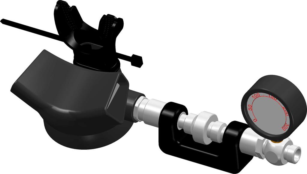
5 Pre Test Before Disassembly: First stage IP high/low tank pressure test sweep and drift. 2ed stage cracking effort at 9,0-10bar IP. Primary preset: (mm of water) Octopus preset: (mm of water) Disassemble Forethought Preparation. Check existing orifice depth. Mean the full set of the LP seat and Orifice, the depth of the set be determined by the Orifice profile (Shape end). Check existing nylon insert nut location The nylon insert should lock the poppet well. If the nylon insert cannot work or loosing, should replace a new nylon insert nut. Disassembly procedures Step1: Remove the Cover ring, PU cover (some of types are the solid front cover with spring purge button) and Diaphragm form Main housing, and set aside. Use the P92 Inline tool adjustment install into the II stage R1 Pro hose inlet end, turn the P92 counter-clockwise to loosen the Orifice for the Coupling. 5
6 6
7 Step2: Apply a 19mm Hex key socket on the coupling, turn counter-clockwise to loosen the coupling. Remove and discard the static O-ring from the coupling. Separate the Orifice form coupling. Step3: Step3-1: for II stage R1 Pro Remove the Side Plug form Main Housing (Press the snap and push out the Side Plug from Main Housing inside.). Remove and discard the static O-ring form Side Plug. Step3-2: for II stage R2 Ice/Special Remove and discard the decal form the Adjustment knob. Apply a screwdriver into the knob screw and turn counter-clockwise to loosen the 7
8 screw. Separate the adjustment knob. Apply a 19mm hex key socket on the adjustment nut, turn it counter-clockwise until the nut full loosen form the body. Separate the Adjust Spring, Adjust Piston, Remove and discard the static O-ring, keep the Teflon washer. Step3-2.1 Apply a O-ring pick tooling on the decal, remove and discard the decal Step3-2.2 A. Apply a screw driver on the Knob Nut. Disassembly the Knob Screw and Adjust Knob and set aside. B. Apply 19mm Hex key socket on the Knob Nut, turn counter-clockwise to loosen the Knob Nut. C. Separate the Adjust Cap Nut, Adjust Shift, 010 O-Ring, Adjust Screw, Adjust Spring and Transmitter Piston, set all aside and discard the 010 O-Ring. 8
9 Step3-2.3 A. Push the Adjust Tube into the Main Housing to disassembly. B. Remove the Adjust Tube from Main Housing. B A Step3-2.4 Remove and discard the 015 O-Ring from the Adjust Tube. Step4: Apply a poppet driver tool into the main housing form brass nut insert, hold it. Apply a 1/4 hex key socket on the nylon insert nut. Hold on the hex key socket; turn the poppet tool to loosen the nylon insert nut. Separate the lever arm, thin poppet washer and thick poppet washer form internality. Remove and discard the LP seat. 9
10 Step5: Remove the C-clip from the Venturi knob. Remove and discard the O-ring, set the Venturi knob aside. 10
11 Step6: Remove the Nylon trip and mouthpiece form Main Housing. Immerse the Main housing into the hot water. Soften and remove the exhaust tee, Remove the exhaust valve. Cleaning Preventive Procedures: Protect orifice and all threads form damage. 11
12 Use Scubatech s specified cleaning & degreasing agents & procedures. Clean procedures: For Metal parts: All metal parts should be cleaned first in a warm (not over 55C) mild soap and water solution. Use a soft nylon bristle brush to help remove any excess or loose contamination. After an initial warm water and soap cleaning all parts should be thoroughly rinsed in clean fresh water and dried with filtered low pressure (2 bar) air. After an initial cleaning in warm soap and water solution, metal parts should be cleaned in an ultrasonic cleaner using the appropriate ultrasonic cleaning solution (see Lubricant and Cleaner Table 2, the Crystal Simple Green cleaner usually use on the Oxygen Clean). For Plastic parts: All plastic parts should be cleaned first in a warm (not over 40C) mild soap and water solution. Use a soft nylon bristle brush to help remove any excess or loose contamination. After an initial warm water and soap cleaning all parts should be thoroughly rinsed in clean fresh water and dried with filtered low pressure (2,0 bar) air. After an initial cleaning in warm soap and water solution, metal parts should be cleaned in an ultrasonic cleaner using the appropriate ultrasonic cleaning solution. NOTICE Be sure all O-rings are removed before cleaning in an ultrasonic cleaner or chemical bath. Cleaning solutions may damage these components. Parts Inspection Preventive Trouble Shooting: Replace dynamic O-rings All O-rings should be replaced at every servicing. New O-rings should be inspected for contamination and/or imperfections, and lightly dressed with a thin 12
13 film of approved lubricant prior to installation. (See Lubricant and Cleaner, Table 2.) Do not use any petroleum based lubricants or products, or any aerosol silicone sprays on any part of Scubatech regulators. The petroleum base or propellant gas may attack or weaken plastic or rubber parts. Refer to Table 2 for a list of approved lubricants. Replace LP seat. (set the shiny side on top) Replace nylon insert nut (if needs) Replace POM orifice (maybe the old Orifice still work, but must replace this for the safety solution) Inspect diaphragm for cuts and holes (if damaged, replace it ) Inspect exhaust valve for damage, check the round edge. Replace it for damage Inspect the LP seat for imperfection. Check through hole on air balanced poppet Inspect hose outer cover at fitting junction Assembly Preventive Procedures: Special tools where required to protect parts. Use orifice preset tool when available Use Scubatech s recommended lubricants Torque assemblies where specified Demand valve Setup Prior to Turing Air On: 13
14 Preset orifice to approximate depth with Preset tool Thread depth reference the cracking effort preset for Primary or Octopus Preset nylon insert nut to end point: Poppet thread must be full completely through the nylon insert Preset recommended thread exposure beyond nylon insert nut turn back about 3.5 turns for preset Preset lever to Maximum height with only a slight amount of slack Do not install diaphragm assembly in this time Install inline adjusting tool (P92) if required Connect LP hose form the first stage Pressurize 2ed stage Watch for lever drop when air pressure is applied Recheck IP for correct pressure range and drift II stage R1Pro Schematic Drawing 14
15 15
16 II stage R2 Ice/Special Pro -P Schematic Drawing 16
17 The II stage R1Pro Downstream Demand valve reassemble and adjustments: The laws of downstream demand valve adjustments. The cracking effort of the valve is a direct result of the force required to depress the lever The force required to depress the lever, and open the valve, is a direct result of spring load. The spring load required to seal the valve airtight is the direct result of overcoming IP downstream force, plus all seating force factors. Always adjust the lever to maximum height to insure full poppet orifice separation. Assemble inner valve components: Poppet, spring, Lever, Washers and nylon insert nut. Note: install poppet threads completely full through the nylon insert, turn back 3 or 3.5 turns of the nylon insert nut. Install the orifice with static O-ring into coupling Install the coupling with static O-ring into the Main Housing, adjust the orifice by inline adjusting tool with the lever depressed to prevent cutting the soft seat. Adjust nylon insert nut to allow for slight lever slack Pressurize the valve at correct IP. If the demand valve leak initially, one of the following conditions exist and must be rectified before continuing: 17
18 There is no slack in the lever (lever loosing) The IP is too high The spring is too weak Poor seating result between the orifice and LP seat. If the demand valve dose not leak: Back the orifice outward until the valve leaks air, than turn the orifice inward until the leak stops, Note: the orifice may need to be readjusted after the LP seat has taken an initial set during the break in period. Depress lever several times to be certain that the valve will seal airtight when the lever is released Install and secure diaphragm, top cover and cover ring assembly. Note: if diaphragm assembly causes the demand valve to leak air, the lever is too high. Turn the orifice inward until the leak stops. Install the side plug with static O-ring into the Main Housing Install the 2ed stage onto flow bench. Check the 2ed stage cracking effort The II stage R2 Ice/Special adjustable downstream 2ed stage reassemble and adjustments: Additional step form Install into SECOND STAGE TROUBLESHOOTING 18
19 SYMPTOM CAUSE ACTION REQUIRED Leaking or Freeflow from 2 ed stage Low purge or excessive work of breathing (full cylinder pressure) 1. High 1 st stage intermediate pressure.(should be 9-10 Bar) 2. LP seat (12) damaged or worn 3. Orifice (14) incorrectly adjusted Lever Arm (16) set too low. 4. Orifice(14) sealing surface damaged 5. Main Spring (13) damaged. 1. Low intermediate pressure. (should be 9-10 bar) 2. Lever Arm(16) not properly engaged with shuttle valve 3. Orifice (14) incorrectly adjusted, Lever Arm(16) set too low 4. Intermediate pressure hose Intermediate pressure hose External air leakage 1. Intermediate pressure hose loose. (Immersion Test) 2. Orifice O-ring(15) damaged 3. Main Housing(1) damaged 1. Refer to first-stage Troubleshooting Guide 2. Replace rubber seating 3. Reset crown and perform Final Tuning & Testing procedures. 4. Replace Orifice 5. Replace poppet spring. 1. Refer to first-stage Troubleshooting Guide. 2. Disassemble and inspect condition of shuttle valve and lever 3. Reset Orifice and perform Final Tuning & Testing procedures 4. Clean or replace hose. 1. Tighten to 40 inch-lbs at female second-stage fitting 2. Disassemble and replace O- ring. 3. Disassemble and replace case. Water entering second-stage 1. Hole in mouthpiece (5). 2. Demand diaphragm(9) damaged 3. Exhaust valve diaphragm(3) damaged 4. Venture knob O-ring(11) dirty, damaged, or worn 5. Main Housing (1) damaged. (Check exhaust valve sealing surface.) 6. Heat Sink O-ring (6) damaged. 1. Replace mouthpiece 2. Replace demand diaphragm 3. Replace exhaust valve diaphragm. 4. Disassemble and replace O- ring. 5. Disassemble and replace case 6. Disassemble and replace O- ring. 19
SCUBAPRO Repair Guide. S600-S550 Second Stages
 SCUBAPRO Repair Guide S600-S550 Second Stages S600 Configuration A S600 Configuration B USE THIS GUIDE AS A REFERENCE WHEN SERVICING THE S600 AND S550 SECOND STAGES S550 P/N 41-047-000 FOR REPAIR OF S600-S550
RG1200 Service and Repair Manual
 Dive Rite RG 1200 Regulator Service and Repair Manual Page 1 Text and Photography by Pete Nawrocky Copyright ( ) 1999-2000, Lamartek, Inc., dba Dive Rite RG1200 Service and Repair Manual First Stage.........................................
R5 Tec Black DIN / Yoke 1 st Stage Service and Repair Manual
 R5 Tec Black DIN / Yoke 1 st Stage Service and Repair Manual Version 1.1, May 1, 2014 Disclaimer This document is proprietary to Scubatech Sp. z o. o. ("Scubatech") and no ownership rights are hereby transferred.
Apeks T20 First St age Service & Repair Manual. for Authorized Sea Quest Service Centers Sea Quest, Inc.
 Apeks T20 First St age Service & Repair Manual for Authorized Sea Quest Service Centers 2000 Sea Quest, Inc. Contents Introduction... 3 Safety Precautions... 3 General Procedures... 3 Maintenance Schedules...
500SE SECOND STAGE SERVICE PROCEDURE
 500SE SECOND STAGE SERVICE PROCEDURE This 500SE Service Procedure conveys a list of components and service procedures that reflect the 500SE as it was configured at the time of this writing. CONTENTS TROUBLESHOOTING...
G250/G250 HP Compatibility of Upgrade Kit
 Engineering Bulletin December 15, 1999 #266 G250/G250 HP Compatibility of Upgrade Kit Page 1 of 9 The SCUBAPRO G250 HP is a marked improvement on the proven G250 second stage design. So much so that issues
Balanced SCUBA Second Stage Regulator (P/N ) Maintenance Manual Contents
 Maintenance Manual Contents") Before Going Further Introduction Balanced SCUBA Second Stage Regulator (P/N 200-120) Maintenance Manual Contents SCBAL-1 SCBAL-1 SCBAL-1 SCBAL-2 SCBAL-2 SCBAL-2 SCBAL-2 SCBAL-2 SCBAL-3 SCBAL-3 SCBAL-3
Before Going Further Introduction Balanced SCUBA Second Stage Regulator (P/N 200-120) Maintenance Manual Contents SCBAL-1 SCBAL-1 SCBAL-1 SCBAL-2 SCBAL-2 SCBAL-2 SCBAL-2 SCBAL-2 SCBAL-3 SCBAL-3 SCBAL-3
12S 1st Stage. -Maintenance Procedure-
 12S 1st Stage -Maintenance Procedure- 1 Warning! All maintenance and repair procedures MUST be performed by a Mares authorized Service Center and/or Distributor. Therefore, the information provided below
MAINTENANCE PROCEDURE FOR X 650
 MAINTENANCE PROCEDURE FOR X 650 X 650 25. juli 2005-1/6 MAINTENANCE PROCEDURE FOR X 650 2 ND STAGE WARNING: This maintenance procedure is only for appointed Scubapro technicians that completed a course
 INTRODUCTION The instructions set forth in this document are intended to guide the experienced scuba equipment repair technician through the standard service procedure for this Sherwood regulator. It is
Contents. Stainless Steel Side Block. 1.1 Separating the Side Block. Stainless Steel Side Block Reassembly of. Assembly from the Helmet Shell
 Separating the Side Block Assembly from the Helmet Shell Contents SSB-1 SSB-3 SSB-5 SSB-5 SSB-7 1.1 Separating the Side Block Assembly from the Helmet Shell 1.2 Side Block Assembly Replacement 1.3 Defogger
SERVICE INSTRUCTIONS
 SERVICE INSTRUCTIONS GEMINI BREATHABLE INFLATOR SR9000 INTRODUCTION The instructions set forth in this document are intended to guide the experienced scuba equipment repair technician through the standard
Service & Repair Manual
 Powerline Inflator (With Dual Valve) Service & Repair Manual for Authorized Sea Quest Service Centers Doc. No. 42983 1999 Sea Quest, Inc. 2 Sea Quest Powerline Service and Repair Manual Contents Introduction...
Balanced SCUBA Second Stage Regulator (P/N ) Contents
 Contents") Introduction (P/N 200-120) Contents SCBAL-1 SCBAL-1 SCBAL-1 SCBAL-2 SCBAL-2 SCBAL-2 SCBAL-2 SCBAL-2 SCBAL-3 SCBAL-3 SCBAL-3 SCBAL-3 SCBAL-4 1.1 Before Going Further 1.2 General Information 1.2.1 Introduction
Introduction (P/N 200-120) Contents SCBAL-1 SCBAL-1 SCBAL-1 SCBAL-2 SCBAL-2 SCBAL-2 SCBAL-2 SCBAL-2 SCBAL-3 SCBAL-3 SCBAL-3 SCBAL-3 SCBAL-4 1.1 Before Going Further 1.2 General Information 1.2.1 Introduction
SERVICE AND REPAIR MANUAL ALTAIR OCTO PN RG300. Service & Repair Manual. Revised - 02/11
 SERVICE AND REPAIR MANUAL ALTAIR OCTO PN RG300 Service & Repair Manual Revised - 02/11 AltAir Octo Contents Section 1 - Introduction Scheduled Service... 3 EAN/ Nitrox Service... 3 Facility Requirements...
Hydraulic Punch Drivers
 SERVICE MANUAL 7804SB / 7806SB Quick Draw 7704SB / 7706SB Quick Draw Flex Quick Draw Hydraulic Punch Drivers Serial Codes AHJ and YZ Read and understand all of the instructions and safety information in
Regulators repair and maintenance. XS Compact 2nd stage. January 2014 Rev XSC /3 Ed. C /14 1
 XS Compact 2nd stage January 2014 Rev XSC /3 Ed. C /14 1 XS Compact 2nd stage WARNING! This manual is intended for use by expert technicians who have already received training in equipment repairs and
SERVICE AND REPAIR MANUAL SPIRIT REGULATOR PN RG100. Service & Repair Manual. Revised - 02/11
 SERVICE AND REPAIR MANUAL SPIRIT REGULATOR PN RG100 Service & Repair Manual Revised - 02/11 Spirit Regulator Contents Section 1 - Introduction Warnings, Cautions, & Notes... 3 Scheduled Service... 3 EAN/
SERVICE AND REPAIR MANUAL SEAAIR REGULATOR PN RG200. Service & Repair Manual. Revised - 02/11
 SERVICE AND REPAIR MANUAL SEAAIR REGULATOR PN RG200 Service & Repair Manual Revised - 02/11 SeaAir Regulator Contents Section 1 - Introduction Warnings, Cautions, & Notes...3 Scheduled Service...3 EAN/
SECOND STAGE SERVICE GUIDE
 SECOND STAGE SERVICE GUIDE 200_08 SRB1000 INTRODUCTION The instructions set forth in this document are intended to guide the experienced scuba equipment repair technician through the standard service procedure
THERE WHEN YOU NEED IT
 SPARE AIR SERVICE MANUAL FOR ALL MODELS 18072 Gothard Street, Huntington Beach, CA 92648 USA 800-648-DIVE P: 714-842-6566 F: 714-842-4626 www.spareair.com e-mail: info@submersiblesystems.com THERE WHEN
SCUBAPRO. Balanced Power Inflator
 SCUBAPRO Balanced Power Inflator USE THIS GUIDE AS A REFERENCE WHEN SERVICING THE BALANCED POWER INFLATOR Important note: The following information is not designed to be a complete training guide for servicing
RS(H)20, 25 USER MANUAL
20, 25 USER MANUAL") RS(H)20, 25 USER MANUAL Read the complete manual before installing and using the regulator. WARNING Before removing a regulator from the system for service, you must depressurize system purge the system
RS(H)20, 25 USER MANUAL Read the complete manual before installing and using the regulator. WARNING Before removing a regulator from the system for service, you must depressurize system purge the system
Booster Pump PB4-60 Replacement Kits
 Booster Pump PB4-60 Replacement Kits FOR YOUR SAFETY - This product must be installed and serviced by a contractor who is licensed and qualified in pool equipment by the jurisdiction in which the product
Deep Six Signature Regulator Technician Service Manual
 Deep Six Signature Regulator Technician Service Manual Copyright 2017 Deep Six Expedition Dive Gear Author UDM Consulting All rights reserved. DEDICATION This manual is dedicated to those who choose to
OCTO SRB9150 SRB9350 BRUT MAGNUM SECOND STAGES SERVICE GUIDE
 SR9952 OCTO SRB9150 SRB9350 BRUT MAGNUM SECOND STAGES SERVICE GUIDE 1 INTRODUCTION The instructions set forth in this document are intended to guide the experienced scuba equipment repair technician through
Product Information News September 26, 2003
 Product Information News September 26, 2003 LEVER HEIGHT INSPECTION FOR FIREHAWK MMR MSA is announcing a revision to the instructions for the Firehawk MMR Second Stage Regulator as they relate to the air
The Envoy. Regulator Service Manual. For Zeagle Envoy 1st and 2nd Stage Scuba Regulators
 The Envoy Regulator Service Manual For Zeagle Envoy 1st and 2nd Stage Scuba Regulators Envoy 1st Stage Parts ITEM # PART # DESCRIPTION... 3 341-0152-AA Label 5 341-0103-CD Spring Adjuster 6 341-0102-CD
PRS(TC)4,8 USER MANUAL. Read the complete manual before installing and using the regulator.
4,8 USER MANUAL. Read the complete manual before installing and using the regulator.") PRS(TC)4,8 USER MANUAL Read the complete manual before installing and using the regulator. WARNING INCORRECT OR IMPROPER USE OF THIS PRODUCT CAN CAUSE SERIOUS PERSONAL INJURY AND PROPERTY DAMAGE. Due to
PRS(TC)4,8 USER MANUAL Read the complete manual before installing and using the regulator. WARNING INCORRECT OR IMPROPER USE OF THIS PRODUCT CAN CAUSE SERIOUS PERSONAL INJURY AND PROPERTY DAMAGE. Due to
RS(H)10,15 USER MANUAL. Read the complete manual before installing and using the regulator.
10,15 USER MANUAL. Read the complete manual before installing and using the regulator.") RS(H)10,15 USER MANUAL Read the complete manual before installing and using the regulator. WARNING INCORRECT OR IMPROPER USE OF THIS PRODUCT CAN CAUSE SERIOUS PERSONAL INJURY AND PROPERTY DAMAGE. Due to
RS(H)10,15 USER MANUAL Read the complete manual before installing and using the regulator. WARNING INCORRECT OR IMPROPER USE OF THIS PRODUCT CAN CAUSE SERIOUS PERSONAL INJURY AND PROPERTY DAMAGE. Due to
Operating Instructions Model and Hydrostatic Test Pump
 Operating Instructions Model 39300 and 39301 Hydrostatic Test Pump Dimension Weight Pump Style Capacity Pressure Motor Lubrication Control Gauge Inlet Connection Outlet Connection Discharge Hose Hose Ends
Installation Instructions
 Installation Instructions S65-135 (Circular) S65-136 (Semi-Circular) Air Valve Retrofit For Non-Sectional Classic Washfountain Table of Contents.......................2-6 Metering Air Valve Parts List....................6
KIRBY MORGAN SUPERFLOW REGULATOR OPERATIONS AND MAINTENANCE MANUAL
 KIRBY MORGAN SUPERFLOW REGULATOR OPERATIONS AND MAINTENANCE MANUAL Manual Prepared by Dive Lab, Inc. Copyright 2003, Dive Lab, Inc. All Rights Reserved TABLE OF CONTENTS 2 SECTION 1.0 GENERAL INFORMATION
TECHNICAL TRAINING SS1
 TECHNICAL TRAINING SS1 2003 1 Limited Lifetime Warranty Atomic Aquatics warrants the SS1 safe second/inflator against defects in materials and workmanship for the lifetime of the original owner with the
CONSHELF XIV TECHNICAL MANUAL
 CONSHELF XIV TECHNICAL MANUAL Rev. 3/17 2 Conshelf XIV Technical Manual COPYRIGHT NOTICE This manual is copyrighted, all rights reserved. It may not, in whole or in part, be copied, photocopied, reproduced,
REGULATORS OMEGA II SECOND STAGE TROUBLE SHOOTING SYMPTOM POSSIBLE CAUSE TREATMENT
 TOUBLE SHOOTING SYMPTOM POSSIBLE CAUSE TEATMENT * Freeflow 1. Incorrectly positioned during water entry. 2. Second stage adjusted too sensitively. 3. Excessive intermediate pressure from first stage. 4.
LRS(H)4 USER MANUAL. Read the complete manual before installing and using the regulator.
4 USER MANUAL. Read the complete manual before installing and using the regulator.") LRS(H)4 USER MANUAL Read the complete manual before installing and using the regulator. WARNING INCORRECT OR IMPROPER USE OF THIS PRODUCT CAN CAUSE SERIOUS PERSONAL INJURY AND PROPERTY DAMAGE. Due to the
LRS(H)4 USER MANUAL Read the complete manual before installing and using the regulator. WARNING INCORRECT OR IMPROPER USE OF THIS PRODUCT CAN CAUSE SERIOUS PERSONAL INJURY AND PROPERTY DAMAGE. Due to the
SR2 Service Manual - Second Stage -
 SR2 Service Manual - Second Stage - 1 INTRODUCTION The instructions set forth in this document are intended to guide the experienced scuba equipment repair technician through the standard service procedure
LRS(H)4 Pressure-Reducing Regulator User Manual
4 Pressure-Reducing Regulator User Manual") LRS(H)4 Pressure-Reducing Regulator User Manual Read the complete manual before installing and using the regulator. 2 Safe Product Selection When selecting a product, the total system design must be considered
LRS(H)4 Pressure-Reducing Regulator User Manual Read the complete manual before installing and using the regulator. 2 Safe Product Selection When selecting a product, the total system design must be considered
Contents. REX Regulator and Oral Nasal. 1.1 Regulator Performance Kirby Morgan Tools for the REX REX Regulator
 Regulator Performance Contents REX-1 REX-1 REX-1 REX-2 REX-2 REX-3 REX-3 REX-4 REX-5 REX-6 REX-6 1.1 Regulator Performance 1.1.1 REX Regulator 1.1.2 Kirby Morgan Tools for the REX Regulator 1.2 REX Demand
RD(H)20/25 Pressure-Reducing Regulator User Manual
20/25 Pressure-Reducing Regulator User Manual") RD(H)20/25 Pressure-Reducing Regulator User Manual Read the complete manual before installing and using the regulator. 2 Safe Product Selection When selecting a product, the total system design must be
RD(H)20/25 Pressure-Reducing Regulator User Manual Read the complete manual before installing and using the regulator. 2 Safe Product Selection When selecting a product, the total system design must be
MMR Air Mask With. with Quick-Connect Hose
 MMR Air Mask With with Quick-Connect Hose Upgrade Kits P/N 10025120 Slide to Connect P/N 10050038 Slide to Connect w/ Solid Cover P/N 10038666 Push To Connect P/N 10050037 Push To Connect w/ Solid Cover
Hydraulic Punch Drivers
 INSTRUCTION MANUAL 7804SB / 7806SB Quick Draw 7704SB / 7706SB Quick Draw Flex 7904SB / 7906SB Quick Draw 90 Quick Draw Hydraulic Punch Drivers Serial Codes AHJ, YZ, and ZA Read and understand all of the
Service and Repair Operative Manual MC9 1 st STAGE. MC9 1 st Stage. 1 st STAGE MC9. Jannuary Rev. MC9 /B Ed. C/13
 MC9 1 st Stage 137 1 st STAGE MC9 Jannuary 2009 - Rev. MC9 /B Ed. C/13 138 WARNING! This manual is intended for use by expert technicians who should attend or have already received training in equipment
Carter Option X Valve connector assembly. Maintenance manual
 Carter Option X Valve connector assembly Maintenance manual Table of contents Description Page 1.0 Introduction... 3 1.1 Safety equipment and procedure... 3 1.2 Maintenance safety alerts... 3 2.0 Equipment
Maintenance and Repair. AirHawk II Air Mask. Second Stage Regulator. Order No.: /02 Prnt. Spec (I) MSAsafety.
 MSAsafety.") Maintenance and Repair Second Stage Regulator Order No.: 10104241/02 Prnt. Spec. 10000005389(I) MSAsafety.com WARNING! Read this manual carefully before servicing the device. The device will perform as
Maintenance and Repair Second Stage Regulator Order No.: 10104241/02 Prnt. Spec. 10000005389(I) MSAsafety.com WARNING! Read this manual carefully before servicing the device. The device will perform as
5 Gallon Pressure Pot with HVLP Spray Gun and Hose
 California Air Tools 5 Gallon Pressure Pot with HVLP Spray Gun and Hose Model No. 365 Technical Data Type of feed.pressure Maximum pressure in the tank... 0,413Mpa (60PSI) Working pressure in the tank.0,
DRAFT 12/17/03 KMB 18/28 (BANDMASK) OVERHAUL, MAINTENANCE, AND INSPECTION CHECKLIST APPENDIX A
 OVERHAUL, MAINTENANCE, AND INSPECTION CHECKLIST APPENDIX A") KMB 18/28 (BANDMASK) OVERHAUL, MAINTENANCE, AND INSPECTION CHECKLIST APPENDIX A2.1 12-17-03 THIS INSPECTION AND MAINTENANCE MUST BE PERFORMED AT LEAST ANNUALLY AND AS DICTATED BY CONDITION REVEALED DURING
KMB 18/28 (BANDMASK) OVERHAUL, MAINTENANCE, AND INSPECTION CHECKLIST APPENDIX A2.1 12-17-03 THIS INSPECTION AND MAINTENANCE MUST BE PERFORMED AT LEAST ANNUALLY AND AS DICTATED BY CONDITION REVEALED DURING
RG3100 and RG3100Ice Regulator System
 RG3100 and RG3100Ice Regulator System User Guide www.diverite.com Date of purchase: www.diverite.com RG1208-5 & RG1208-5Ice www.diverite.com First Stage Regulator Product Description The RG1208-5 and RG1208-5Ice
CS150 CAP STAPLER OWNER S MANUAL
 Operation Revised 6/2013 www.stingerworld.com CS150 CAP STAPLER OWNER S MANUAL! Maintenance Safety Warranty PLEASE READ! This manual contains important information about product safety. WELCOME TO STINGER
Helium-Oxygen Blender
 Helium-Oxygen Blender Service Manual Model No. PM5400 Series PM5500 Series (shown) SAVE THESE INSTRUCTIONS 300 Held Drive Tel: (+001) 610-262-6090 Northampton, PA 18067 USA Fax: (+001) 610-262-6080 www.precisionmedical.com
Model VR6 System. Installation, Operation & Maintenance
 Model VR6 System Installation, Operation & Maintenance General: All Archer Instruments chlorination systems are carefully designed and tested for years of safe, accurate field service. All Archer Instruments
RHPS Series PRV 6 User Manual
 RHPS Series PRV 6 User Manual Read the complete manual before installing and using the valve. 1 WARNING Before removing a valve from the system for service, you must depressurize system purge the system
Model 23H Hand Crank Seamer
 OPERATOR'S MANUAL Model 23H Hand Crank Seamer If you are not experienced with your seamer, please read and understand this manual before operating the machine. If you have a question discuss it with your
AUTHORIZED TECHNICIAN TECHNICAL MAINTENANCE MANUAL CALYPSO FIRST STAGE
 AUTHORIZED TECHNICIAN TECHNICAL MAINTENANCE MANUAL CALYPSO FIRST STAGE Contents Copyright notice...3 Introduction...3 Warnings, Cautions, & Notes...3 Scheduled Service...3 General Guidelines...3 General
RHPS Series RD(H)F40 User Manual. Read the complete manual before installing and using the regulator.
F40 User Manual. Read the complete manual before installing and using the regulator.") RHPS Series RD(H)F40 User Manual Read the complete manual before installing and using the regulator. 2 WARNING Before removing a regulator from the system for service, you must depressurize system purge
RHPS Series RD(H)F40 User Manual Read the complete manual before installing and using the regulator. 2 WARNING Before removing a regulator from the system for service, you must depressurize system purge
SERVICE MANUAL LEGEND FIRST STAGE
 SERVICE MANUAL LEGEND FIRST STAGE Copyright 2005 Aqualung France Rev. 02/2005 2 Legend First Stage Service Manual Index COPYRIGHT... 3 INTRODUCTION... 3 WARNINGS, ATTENTION, NOTE...... 3 MAINTENANCE...
Hydraulic Piston Accumulators
 Ride Control Engineering Services PWCE Extendavator Paul Wever Construction Equipment Co., Inc. P.O. Box 85 401 Martin Drive Goodfield, IL 61742-0085 Phone (309) 965-2005 Fax (309) 965-2905 1-800-990-PWCE
Helicopter Aircrew Breathing Device (H.A.B.D.) User s Manual
 User s Manual") Helicopter Aircrew Breathing Device (H.A.B.D.) User s Manual Rev 02/16 2 H.A.B.D. User s Manual COPYRIGHT NOTICE This owner s manual is copyrighted, all rights reserved. It may not, in whole or in part,
Helicopter Aircrew Breathing Device (H.A.B.D.) User s Manual Rev 02/16 2 H.A.B.D. User s Manual COPYRIGHT NOTICE This owner s manual is copyrighted, all rights reserved. It may not, in whole or in part,
Product Information News
 Product Information News MMR SECOND STAGE REGULATOR VALVE CORE MSA has changed its recommended rebuilding of the MMR Second Stage Regulator s bypass sleeve assembly during the annual inspection. Based
SAFETY MEASURES. These important guidelines should always be followed to work safely with the PRIMATECH pneumatic stapler model Q180:
 PRIMATECH PNEUMATIC 18GA STAPLER Q180 The pneumatic flooring stapler Q180 is a professional precision tool specially developed for the installation of most of 3/8" to 5/8" solid and engineered hardwood
HPB25 Hydraulic Paving Breaker
 INSTRUCTION MANUAL HPB25 Hydraulic Paving Breaker Read and understand all of the instructions and safety information in this manual before operating or servicing this tool. Register this product at www.greenlee.com
ADMINISTRATION GENERAL INFORMATION OCEANIC ADMINISTRATION FOR PRODUCT SERVICE PROCEDURES
 OCEANIC FOR PRODUCT SERVICE PROCEDURES The Product Service Guide conveys lists of components and service procedures that reflect the products as they are configured at the time of their writing. They also
200 PSI COMPRESSORS - MODEL NUMBERS
 200 PSI COMPRESSORS - MODEL NUMBERS 380C AIR COMPRESSOR KIT PART NO. 38033 480C AIR COMPRESSOR KIT PART NO. 48043 380C 480C IMPORTANT: It is essential that you and any other operator of this product read
100C Air Compressor Kit
 10010 100C Air Compressor (standard mounting bracket, CE Spec) 10014 100C Air Compressor (no leader hose or check valve, CE Spec) 10016 100C Air Compressor (with Omega Bracket, CE Spec) IMPORTANT: It is
WARNING: Indicates a potentially hazardous situation which, if not avoided, could result in death or serious injury.
 This owner s manual uses signal words recommended by the American National Standards Institute (see ANSI Z535.4) to designate levels of hazard seriousness. These signal words and their designations are
Air-Oxygen Blender. Service Manual. Model No. PM5200 Series PM5300 Series (shown)
") Service Manual Model No. PM5200 Series PM5300 Series (shown) SAVE THESE INSTRUCTIONS 300 Held Drive Tel: (+001) 610-262-6090 Northampton, PA 18067 USA Fax: (+001) 610-262-6080 www.precisionmedical.com
Service Manual Model No. PM5200 Series PM5300 Series (shown) SAVE THESE INSTRUCTIONS 300 Held Drive Tel: (+001) 610-262-6090 Northampton, PA 18067 USA Fax: (+001) 610-262-6080 www.precisionmedical.com
Regulators repair and maintenance. 1st stage MC5. MC5 INT HZ MC5 DIN 300 bar HZ
 1st stage MC5 MC5 INT HZ 800098 MC5 DIN 300 bar HZ 800099 January 2008 Rev. MC5 / 1 Ed. A / 08 1 1st stage MC5 WARNING! This document is intended for experienced technical personnel who have already attended
420C AIR COMPRESSOR KIT PART NO C AIR COMPRESSOR KIT PART NO
 420C AIR COMPRESSOR KIT PART NO. 42042 460C AIR COMPRESSOR KIT PART NO. 46043 420C 460C IMPORTANT: It is essential that you and any other operator of this product read and understand the contents of this
SERVICE & REPAIR MANUAL H.A.B.D.
 Authorized Technician SERVICE & REPAIR MANUAL H.A.B.D. (Helicopter Aircrew Breathing Device) Rev. 02/16 2 H.A.B.D. Service & Repair Manual COPYRIGHT NOTICE This owner s manual is copyrighted, all rights
35 TON HYDRAULIC PUNCH WARNING
 OPERATORS GUIDE REL-35T-PNC 35 TON HYDRAULIC PUNCH NOTICE Sizes, weights and tool specifications listed in this manual are subject to change without notice. Please consult factory for information and updates.
User Instruction Manual
 User Instruction Manual 4500 psi Air Compressor Ver 2, 1.18 Contents Parts Included...3 Assembly Instructions...3-5 Operation Instructions...6-7 Oil Change Intervals...8 Air Filter Replacement...9 Setting
FILTER REGULATORS MODEL NO: CAT155 & CAT156 FITTING & MAINTENANCE INSTRUCTIONS PART NO: & ORIGINAL INSTRUCTIONS
 FILTER REGULATORS MODEL NO: CAT155 & CAT156 PART NO: 3120169 & 3120170 FITTING & MAINTENANCE INSTRUCTIONS ORIGINAL INSTRUCTIONS GC0117 INTRODUCTION Thank you for purchasing this CLARKE Filter/Regulator.
R0001. Northern Diver. HYDRA Regulator Manual
 R0001 v Northern Diver HYDRA Regulator Manual Northern Diver Hydra Reg Manual East Quarry Appley Lane North, Appley Bridge, Wigan, WN6 9AE, UK Owner s manual Copyright Notice: This owners manual is copyrighted,
KMB 18/28 (BANDMASK) OVERHAUL, MAINTENANCE, AND INSPECTION CHECKLIST APPENDIX A
 OVERHAUL, MAINTENANCE, AND INSPECTION CHECKLIST APPENDIX A") KMB 18/28 (BANDMASK) OVERHAUL, MAINTENANCE, AND INSPECTION CHECKLIST APPENDIX A2.1 01-31-17 THIS INSPECTION AND MAINTENANCE SHOULD BE PERFORMED AT LEAST ANNUALLY AND AS DICTATED BY CONDITION REVEALED DURING
KMB 18/28 (BANDMASK) OVERHAUL, MAINTENANCE, AND INSPECTION CHECKLIST APPENDIX A2.1 01-31-17 THIS INSPECTION AND MAINTENANCE SHOULD BE PERFORMED AT LEAST ANNUALLY AND AS DICTATED BY CONDITION REVEALED DURING
Assembling & Installing your Pool Cleaner
 Assembling & Installing your Pool Cleaner STEP 1: Check Contents of the Box Remove the Badu Clean Supreme body and all parts from the box and check that the following components are included. Refer to
RHPS Series PRV 2 all types of connections User Manual
 RHPS Series PRV 2 all types of connections User Manual Read the complete manual before installing and using the valve. Before removing a valve from the system for service, you must depressurize system
FIRST AND SECOND STAGE REGULATORS TECHNICAL SERVICE PROCEDURES
 FIRST AND SECOND STAGE REGULATORS TECHNICAL SERVICE PROCEDURES Note: These instructions and schematics are intended for use by qualified regulator repair technicians. They are intended to supplement, not
TX SECOND STAGE REGULATOR
 TECHNICAL SUPPORT TX SECOND STAGE REGULATOR MAINTENANCE MANUAL FOR AUTHORISED TECHNICIANS Document No. AP5833 Issue 1 6/06/2006 APEKS MARINE EQUIPMENT LTD, NEPTUNE WAY, BLACKBURN, LANCASHIRE. BB1 2BT Tel:
accidents which arise due to non-observance of these instructions and the safety information herein. SPECIFICATIONS
 18 GAUGE 1-1/4 INCH BRAD NAILER Model: 7611 CALIFORNIA PROPOSITION 65 WARNING: You can create dust when you cut, sand, drill or grind materials such as wood, paint, metal, concrete, cement, or other masonry.
It's Not Rocket Science, It's Bicycle Maintenance
 TECM 2700.011 It's Not Rocket Science, It's Bicycle Maintenance A Comprehensive Bicycle Maintenance Manual for All Riders Patrick Doran, Bryan Hayes, Ashley Huffman, Corbin Sheridan 4/18/2012 It's Not
LOW PRESSURE INFLATION SYSTEM (LPIS) DRY SUIT INFLATION SYSTEM (DSIS) TECHNICAL MANUAL
 DRY SUIT INFLATION SYSTEM (DSIS) TECHNICAL MANUAL") LOW PRESSURE INFLATION SYSTEM (LPIS) DRY SUIT INFLATION SYSTEM (DSIS) TECHNICAL MANUAL Rev. 6/17 2 LPIS / DSIS Technical Manual COPYRIGHT NOTICE This manual is copyrighted, all rights reserved. It may
LOW PRESSURE INFLATION SYSTEM (LPIS) DRY SUIT INFLATION SYSTEM (DSIS) TECHNICAL MANUAL Rev. 6/17 2 LPIS / DSIS Technical Manual COPYRIGHT NOTICE This manual is copyrighted, all rights reserved. It may
 CS150 CAP STAPLER OWNER S MANUAL Operation Safety Maintenance Warranty! www.stingerworld.com PLEASE READ! This manual contains important information about product safety. REV 06/15 WELCOME TO STINGER Congratula*ons
SG-7R46 SG-7R45 BR-IM41-R CJ-7S40 WARNING CAUTION SERVICE INSTRUCTIONS. Inter-7 Hub. Inter-M Brake Cassette joint NOTE:
 t WARNING It is important to completely understand the operation of your bicycle's brake system. Improper use of your bicycle's brake system may result in a loss of control or an accident, which could
IMPORTANT SAFETY INSTRUCTIONS
 IMPORTANT SAFETY INSTRUCTIONS CAUTION - To reduce risk of electrical shock: - Do not disassemble. Do not attempt repairs or modifications. Refer to qualified service agencies for all service and repairs.
Natural Gas Conversion Kit
 SERIAL #: Attention: Centro recommends that a qualified gas technician perform the gas supply conversion and orifice replacement for this BBQ model. Natural Gas Conversion Kit F O R U S E W I T H M O D
WW-720. Pressure Reducing Control Valve
 WW-720 Pressure Reducing Control Valve (Size Ranges: 2-4 and 6-14 ) Installation Operation & Maintenance Page 1 of 6 1. DESCRIPTION The Model 720 Pressure Reducing is an automatic control valve (powered
WW-730. Pressure Sustaining/Relief Control Valve
 WW-730 Pressure Sustaining/Relief Control Valve Installation Operation & Maintenance Page 1 of 6 1. DESCRIPTION The Model 730 Pressure Relief / Sustaining Valve is an automatic control valve designed to
RG2200 BC Integrated Octopus
 175 NW Washington Street Lake City, Florida 32055, USA Web: www.diverite.com Phone: 386.752.1087 Fax: 386.755.0613 RG2200 BC Integrated Octopus Product description The Rite Source is both a BC inflation/deflation
SERVICE & REPAIR MANUAL H.A.B.D.
 Authorized Technician SERVICE & REPAIR MANUAL H.A.B.D. (Helicopter Aircrew Breathing Device) REVISED 12/07 H.A.B.D. Service & Repair Manual 2 Copyright Notice This owner s manual is copyrighted, all rights
WARNING: Indicates a potentially hazardous situation which, if not avoided, could result in death or serious injury.
 This owner s manual uses signal words recommended by the American National Standards Institute (see ANSI Z535.4) to designate levels of hazard seriousness. These signal words and their designations are
Installation of Your SprayMaster System
 Installation of Your SprayMaster System 1. At the installation site, remove all equipment from the corrugated box and the polyethylene drum and replace the drum lid. Check the picture to identify each
Training. Testor Training Manual
 Training Testor Training Manual Index Section 1 Introduction and Safety Warnings Section 2 Test Procedures Section 3 Test Hoses Section 4 Fault Location 1:1 1.1 Introduction The Dräger Testor test equipment
RG1200 Regulator System
 RG1200 Regulator System UserGuide Date of purchase: www.diverite.com DEVELOPED BY COPYRIGHT NOTICE WARRANTY INFORMATION Dive Rite 175 NW Washington Street Lake City, FL 32055 Phone: 386.752.1087 Fax:
PDY TON HYDRAULIC CRIMPING TOOL WARNING
 OPERATORS ORS GUIDE PDY-1220 12 TON HYDRAULIC CRIMPING TOOL All information found in this guide must be read and understood before use or testing of this tool. Failure to read and understand these warnings
Installation Instructions
 Installation Instructions COLONY SOFT 7.0 Centerset Lavatory Faucet 7.0 with Speed Connect Drain Congratulations on purchasing your American Standard faucet with the Speed Connect drain, a features found
Installation Troubleshooting Maintenance Instructions Installation / Start-up
 Model ZW207 Installation Troubleshooting Maintenance Instructions Installation / Start-up NOTE: Flushing of all pipe lines is to be performed to remove all debris prior to installing valve. 1. For making
Operation & Maintenance Manual Place this manual with valve or person responsible for maintenance of the valve
 Operation & Maintenance Manual Place this manual with valve or person responsible for maintenance of the valve Model CYCLE GARD II, CI & CNA YOUR PRODUCT INFORMATION: Model Number: Date: Serial Number:
accidents which arise due to non-observance of these instructions and the safety information herein. SPECIFICATIONS
 18 GAUGE 2 INCH BRAD NAILER Model: 7555 CALIFORNIA PROPOSITION 65 WARNING: You can create dust when you cut, sand, drill or grind materials such as wood, paint, metal, concrete, cement, or other masonry.
Dive Center Service Manual
 2017 Dive Center Service Manual 2017 - revised 2017 INDEX-A INDEX - Mares Service Manual Contents Pag Last Note Vol revision INTRODUCTION I1 2017 NEW 2 MARES SERVICE MANUAL I1 2017 NEW 2 INTRODUCTION I2