Dive Center Service Manual
|
|
|
- Damian Walton
- 6 years ago
- Views:
Transcription

1 2017 Dive Center Service Manual
2 revised 2017 INDEX-A INDEX - Mares Service Manual Contents Pag Last Note Vol revision INTRODUCTION I NEW 2 MARES SERVICE MANUAL I NEW 2 INTRODUCTION I NEW 2 SYMBOLS I NEW 2 TECHNICAL BULLETINS TECHNICAL INFORMATION S I NEW 2 INDEX AND UPDATE I NEW 2 Regulators FIRST STAGES 12S FIRST STAGE BTM 15 BTM BTM 17 BTM ITM 19 ITM ITM 24 ITM ITM 25 ITM ITM 29 ITM ITM 30 ITM ITM 37 ITM ITM 40 ITM BTM 25_R1 BTM 25_R S. REQUIRED TOOLS AND SUPPLIES F S. DISASSEMBLY F S. DISASSEMBLY DIN-NX F S. DISASSEMBLY F S. INSPECTION AND CLEANING F S. FIRST STAGE SERVICE KIT F S. REASSEMBLY F S. REASSEMBLY DIN-NX F S. REASSEMBLY F S. ADJUSTMENT F S. TROUBLESHOOTING F S. DRAWING E 118 F S. CHART 41 F OCTOPUS MV Pag Last Note Vol revision MV. REQUIRED TOOLS AND SUPPLIES S NEW 2 MV. DISASSEMBLY S NEW 2 MV. INSPECTION AND CLEANING S NEW 2 MV. SECOND STAGE SERVICE KIT S NEW 2 MV. REASSEMBLY S NEW 2 MV. ADJUSTMENT S NEW 2 MV. FINAL ADJUSTMENT S NEW 2 MV. TROUBLESHOOTING S NEW 2 MV. DRAWING E 34 S NEW 2 MV. CHART 124 S NEW 2 Jackets JACKETS ERGO INFLATOR 2017 NEW 2 15X FIRST STAGE ITM 37 ITM ITM 40 ITM BTM 25_R1 BTM 25_R X. REQUIRED TOOLS AND SUPPLIES F X. DISASSEMBLY F X. DISASSEMBLY INT F X. DISASSEMBLY DIN - NX F X. INSPECTION AND CLEANING F X. FIRST STAGE SERVICE KIT F X. REASSEMBLY F X. REASSEMBLY INT F X. REASSEMBLY DIN - NX F X. ADJUSTMENT F X. TROUBLESHOOTING F X. DRAWING E119 F X. CHART 42 F S FIRST STAGE 2S. REQUIRED TOOLS AND SUPPLIES F NEW 2 2S. DISASSEMBLY F NEW 2 2S. DISASSEMBLY DIN F NEW 2 2S. INSPECTION AND CLEANING F NEW 2 2S. FIRST STAGE SERVICE KIT F NEW 2 2S. REASSEMBLY F NEW 2 2S. REASSEMBLY DIN F NEW 2 2S. ADJUSTMENT F NEW 2 2S. TROUBLESHOOTING F NEW 2 2S. DRAWING E 976 F NEW 2 2S. CHART 38 F NEW 2 2S. DRAWING E 976 F NEW 2 2S. CHART 44 F NEW 2 SECOND STAGES ROVER SECOND STAGE ITM 23 ITM NEW 2 ITM 33 ITM NEW 2 ROVER. REQUIRED TOOLS AND SUPPLIES S NEW 2 ROVER. DISASSEMBLY S NEW 2 ROVER. INSPECTION AND CLEANING S NEW 2 ROVER. SECOND STAGE SERVICE KIT S NEW 2 ROVER. REASSEMBLY S NEW 2 ROVER. ADJUSTMENT S NEW 2 ROVER. REASSEMBLY S NEW 2 ROVER. TROUBLESHOOTING S NEW 2 ROVER. DRAWING E 38 S NEW 2 ROVER. CHART 128 S NEW 2
3 revised 2017 Introduction I1 INTRODUCTION Mares S.p.A., based in Salita Bonsen, Rapallo, Italy, manufactures and distributes a complete line of diving equipment. Mares brand is synonymous of excellent quality, which all passionate scuba divers recognize in this name. MARES SERVICE MANUAL This Manual is intended to be used by qualified Mares Service Technicians as a reference guide when servicing and repairing Mares products. Use of this Manual should not be considered a substitute for proper training and qualification as a Mares Service Technician. Drawings and Charts are subject to change. When performing service procedures and ordering parts, please be sure to reference the most recent versions. WARNING POSSESSION OF THIS MANUAL DOES NOT, IN ANY WAY, CONSTITUTE OR IMPLY AUTHORIZATION BY MARES TO SERVICE OR REPAIR MARES PRODUCTS. PERFORMING SERVICE AND/OR REPAIR PROCEDURES ON MARES PRODUCTS BY ANYONE OTHER THAN QUALIFIED MARES SERVICE TECHNICIANS AT AUTHORIZED MARES DEALERS AND SERVICE CENTERS VOIDS ALL MARES WARRANTIES AND THE TECHNICIAN OR DEALER ASSUMES SOLE RESPONSIBILITY AND LIABILITY FOR ANY DAMAGE OR INJURIES WHICH MAY RESULT FROM SUCH SERVICE AND/OR REPAIR PROCEDURES. CAUTION IF ANY INSTRUCTIONS OR PROCEDURES CONTAINED IN THIS SERVICE MANUAL ARE UNCLEAR TO YOU, OR IF YOU HAVE ANY QUESTIONS, PLEASE CONTACT THE LOCAL MARES SUBSIDIARY OR DISTRIBUTOR THAT SERVICES YOUR AREA BEFORE PERFORMING ANY SERVICE AND/OR REPAIR. Mares strongly recommends to carefully read all sections described in this manual before performing any repair/service procedure MARES S.p.A. Salita Bosen, Rapallo (Ge) - ITALY ALL RIGHTS RESERVED. This Manual contains information protected under the International and Federal Copyright Laws and Treaties. Any unauthorized reprint or use of this material is prohibited. No part of this Manual may be reproduced or transmitted in any form or by any means, electronic or mechanical, including photocopying, recording, or by information storage and retrieval system without express written permission from Mares S.p.A.
4 revised 2017 Introduction I2 INTRODUCTION This manual consists of two Volumes: Volume 1 includes products till collection 2014/2015. It won t be modified anymore. Volume 2 includes products from collection 2015/2016 on. Any update will be issued to all qualified Mares Service Technicians. Every single manual is organized as follow: Cover showing the name of the product and a picture. All Technical Information and Technical Bulletin related to the product. Disassembly procedures. Inspection and Cleaning Procedures. Product service Kit. Reassembly Procedures. Adjustment Procedures. Troubleshooting Section. Drawing and Chart. SYMBOLS Any information, notices and precautions concerning operations which may compromise the efficiency of the product, prove dangerous or even fatal for the technician, the owner of the product or other persons, are highlighted by the following symbols: DANGER INDICATES AN IMMINENTLY HAZARDOUS SITUATION WHICH, IF NOT AVOIDED, WILL RESULT IN DEATH OR SERIOUS INJURY. WARNING INDICATES A POTENTIALLY HAZARDOUS SITUATION WHICH, IF NOT AVOIDED, COULD RESULT IN DEATH OR SERIOUS INJURY. CAUTION INDICATES A POTENTIALLY HAZARDOUS SITUATION WHICH, IF NOT AVOIDED, MAY RESULT IN MINOR OR MODERATE INJURY. IT MAY ALSO BE USED TO ALERT AGAINST UNSAFE PRACTICES. Indicates suggestions and recommendations on how to correctly perform certain operations described in the manual.
5 revised 2017 Introduction I3 TECHNICAL BULLETINS TECHNICAL INFORMATION S Each product s service manual includes the ITM and BTM Technical Bulletins that are related to that particular product. ITM and BTM Bulletins will also be periodically issued by Mares as deemed necessary to inform Mares Service Technicians about changes and/or modification to service procedures and parts. Each product s Service Manual will be updated annually. At that time, all previous year s ITM and BTM Bulletins will be added to the product s Service Manual so that all Technical Bulletins related to that product are available for easy reference. Please check with the local Mares Subsidiary or Distributor that services your area for details on annual distribution of updated service manuals. INDEX AND UPDATE The column Last Revision shows the latest year in which a section, document, or page has been modified. The modified section, document, or page replaces the existing one, following the order specified in the index. The column Note is dedicated to new section, document, or page, that need to be added to the Service Manual. The new section, document, or page, marked by the word NEW, must be added to the Service Manual following the order specified in the index. The column Volume show which volume the product belong to.
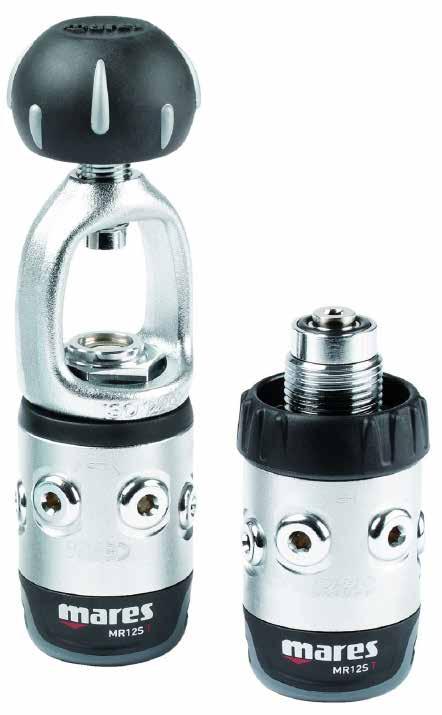
6 12S FIRST STAGE 12S FIRST STAGE
7 revised 2015 Technical Bulletin BTM 15 BTM 15 FIRST STAGE MR12 NITROX CONNECTOR (EN 144-3) MAINTENANCE INSTRUCTION DEC. 21, 2005 FOR COMPONENTS PLEASE REFER TO 2006 SPARE PART LIST - Table 29 drawing 106. FOR FINAL ADJUSTMENT PLEASE CHECK THE MAINTENANCE MANUAL - EN NITROX SECTION. STARTING FROM 2006, MARES MANUFACTURES NITROX REGULATORS TESTED AND APPROVED ACCORDING TO EN 13949:2003 NORM. THE NITROX First Stage ASSEMBLY THE NEW NITROX 200 BAR TYPE CONNECTION IN ACCORDANCE TO THE EN NORM. THE NEW NITROX Connector MUST BE ASSEMBLED ONLY ON VALVES WITH FEMALE CONNECTION M 26X2 IN COMPLIANCE WITH THE EN NORM. WARNING! THESE PROCEDURES APPLY ONLY ON MARES NITROX REGULATORS CERTIFIED ACCORDING TO EN 13949:2003 NORM. THEY SHOULD NOT BE USED AS STANDARD PROCEDURE TO MODIFY OTHER REGULATORS. THE MAINTENANCE OPERATION ON THE NEW NITROX CONNECTOR MUST BE PERFORMED BY ONLY AUTHORIZED QUALIFIED PERSONNEL AT A TECHNICAL ASSISTANCE CENTER AND/OR BY AN AUTHORIZED MARES DISTRIBUTOR. FOR ADJUSTMENT AND INSPECTIONS PLEASE CHECK THE PROCEDURES DESCRIBED IN THE MAINTENANCE MANUAL -NITROX SECTION EN 13949:2003. SHOULD THE UPDATED MANUALS CONTAINING THE SECTIONS INDICATED BE ABSENT, OR IF THE INSTRUCTIONS ARE UNCLEAR OR NOT ENTIRELY UNDERSTANDABLE, PLEASE CONTACT MARES BEFORE PERFORMING ANY MAINTENANCE, ADJUSTMENT OR CHECK. - 1 HEX WRENCH 6mm (B-8 Cod ) Tools - FIRST STAGE TOOL (B-5 Cod ) - 1 WRENCH 32mm (B-16 Cod ) WARNING! MARES RECOMMENDS TO PAY MAXIMUM ATTENTION DURING THE ASSEMBLING, MAINTENANCE AND/OR ADJUSTMENT OPERATIONS LISTED BELOW.
8 revised 2015 Technical Bulletin BTM 15 BTM 15 FIRST STAGE MR12 NITROX Connector (EN 144-3) MAINTENANCE INSTRUCTION DEC. 21, 2005 DISASSEMBLY 1. SCREW THE TOOL (B-5) IN A 3/8 LP PORT (Fig. 1). 2. WITH THE 6MM HEX WRENCH (B-8), UNSCREW THE CONNECTOR FRONT (51) AND REMOVE O-RINGS (50) AND (198). 3. REMOVE THE CONNECTOR WHEEL (49). 4. WITH THE WRENCH (B-16), USCREW THE CONNECTOR BASE (48) AND REMOVE THE O-RING (23). RIASSEMBLY 5. PLACE THE O-RING (23) ON THE CONNECTOR BASE (48). 1 TO AVOID ACCIDENTAL LOOSENING OF THE NITROX CONNECTOR BASE (48) AND THE CONNECTOR FRONT (51), POUR, AWAY FROM THE O-RING, ONE OR TWO DROPS OF SEALING COMPOUND (LOCTITE TYPE 242 E) ON THE THREAD. DO NOT POUR LOCTITE ON THE O-RINGS. 6. TIGHTENING WITH THE 32MM WRENCH (B-16), SCREW THE NITROX CONNECTOR BASE (48) ON THE FIRST STAGE BODY. IF A TORQUE WRENCH IS USED, SET IT ON N.m. 7. PLACE CORRECTLY THE WHEEL (49) ON THE CONNECTOR BASE (48). 8. PLACE THE O-RINGS (50) AND (198) ON THE CONNECTOR SEAT (51). 9. USING THE 6MM HEX WRENCH TIGHTEN THE CONNECTOR SEAT (51) ON THE FIRST STAGE.

9 revised 2015 Technical Bulletin BTM 15 Drawing No.E 106 MR12 NITROX CONNECTOR Drawing updated: 05/25/05 Table No. 29 MR12 NITROX CONNECTOR Drawing reference No.: E 106 Table updated on: 05/25/2005 CHART NO: 29 MR 12 NITROX CONNECTOR UPDATED: 05/25/2005 Ref. No. Part n. DESCRIPTION Ref. No. Part n. DESCRIPTION O-ring 115 Viton OR 3056 Viton Connector - base Nitrox Wheel 200 Bar M26X O-ring 2018 Viton Connector - front Nitrox ASSEMBLY Protection cap 2K5 (yellow) F NITROX Connector 200 BAR

10 revised 2015 Technical Bulletin BTM 17 BTM 17 NEW HP POPPET SEAT FOR MR FIRST STAGES (CODE: ) JAN. 30, 2008 THE TECHNICAL ASSISTANCE DEPARTMENT OF MARES S.P.A. ANNOUNCES A MODIFICATION TO THE PROFILE AND MATERIAL OF THE HP POPPET SEAT USED IN ALL OF MARES MR FIRST STAGES. THE CODE FOR THE NEW HP POPPET SEAT HAS NOT CHANGED AND CAN ONLY BE IDENTIFIED BY THE DESCRIPTION BELOW. THE NEW HP POPPET SEAT WAS DESIGNED AND TESTED TO GUARANTEE A GREATER RESISTANCE TO WEAR AND TEAR. THE NEW HP POPPET SEAT SHOULD ONLY BE USED WITH THE TRI-MATERIAL POPPET, (CODE: ) THE NEW HP POPPET SEAT CAN BE EASILY IDENTIFIED BY THE RADIAL THROAT DESIGN UNDER THE SEAT OF THE OR- RING (AS SHOWN IN PICTURE 1 BELOW). - NEW HP POPPET SEAT - WARNING! THE ASSEMBLING OPERATION OF THE NEW DIN CONNECTOR MUST BE PERFORMED BY ONLY QUALIFIED PERSONNEL AT A TECHNICAL ASSISTANCE CENTRE AND/OR BY AN AUTHORIZED MARES DISTRIBUTOR. FOR THE ASSEMBLY PLEASE FOLLOW THE PROCEDURES DESCRIBED IN THIS TECHNICAL BULLETIN. FOR POSSIBLE ADJUSTMENT PROCEDURE, CHECKS OR COMPONENTS REFERENCE NUMBERS PLEASE CONSULT THE PROCEDURES AND THE DRAWINGS DESCRIBED IN THE MAINTENANCE MANUAL. SHOULD THE UPDATED MANUALS CONTAINING THE SECTIONS INDICATED BE ABSENT, OR IF THE INSTRUCTIONS ARE UNCLEAR OR NOT ENTIRELY UNDERSTANDABLE, PLEASE CONTACT MARES BEFORE PERFORMING ANY MAINTENANCE, ADJUSTMENT OR CHECK. WARNING! MARES RECOMMENDS, WHEN ASSEMBLING THE DIN CONNECTOR, TO PAY PARTICULAR ATTENTION TO THE MAINTENANCE AND/OR ADJUSTMENT OPERATIONS LISTED HERE BELOW. DISASSEMBLY: ASSEMBLE THE DIN CONNECTOR AFTER HAVING DISASSEMBLED, FROM THE FIRST STAGE, THE YOKE RETAINING NUT (7), THE YOKE (3) AND THE YOKE KNOB (25), FOLLOWING THE INSTRUCTIONS IN THE MANUAL RELATED TO YOUR FIRST STAGE.
 SEP.")


11 revised 2015 Technical Information ITM 19 ITM 19 SPECIAL TOOLS (# # ) SEP. 07, 2009 IMPORTANT INFORMATION FOR COMPONENTS PLEASE REFER TO 2006 SPARE PART LIST - Table 29 drawing 106 FOR FINAL ADJUSTMENT PLEASE CHECK THE MAINTENANCE MANUAL - EN NITROX SECTION 12S HP SEAT CONNECTOR DISASSEMBLY TOOL (B-41) INSERT THE TOOL (B-41) IN A LOW PRESSURE POR T AND USE IT TO PRY OUT THE HP SEAT CONNECTOR. Fig. 2 Fig. 3 Fig. 4 Fig. 5
 SEP.")
 IN THE CENTRAL POR T ON THE")
. THEN PRESS (FIG.")
.")
12 revised 2015 Technical Information ITM 19 ITM 19 SPECIAL TOOLS (# # ) SEP. 07, 2009 HP SEAT CONNECTOR DISASSEMBLY TOOL (B-42) INSERT THE TOOL (B-42) IN THE CENTRAL POR T ON THE DIAPHRAGM SIDE UNTIL YOU FEEL IT TOUCH THE SEA T CONNECTOR (FIG. 3). THEN PRESS (FIG. 3) ON THE SEAT CONNECTOR UNTIL IT COMES OUT COMPLETELY (FIG. 4). VALVE PROCEDURE FOR THE MR-V 12/16/22/32/HUB SERIES. Fig. 2 Fig. 3 Fig. 4 Fig. 5


13 revised 2015 Technical Information ITM 19 ITM 19 SPECIAL TOOLS (# # ) SEP. 07, 2009 BELOW IS THE VALVE SEQUENCE FOR MR42 INSERT THE TOOL (B-42) IN THE CENTRAL PORT ON THE DIAPHRAGM SIDE UNTIL YOU FEEL IT TOUCH THE SEAT CONNECTOR (FIG. 3). THEN PRESS ON IT (FIG. 4) UNTIL YOU COMPLETEL Y REMOVE THE SEAT CONNECTOR. Fig. 2 Fig. 3 Fig. 4 Fig. 5
14 revised 2015 Technical Information ITM 24 ITM 24 PARBAK BACKUP RING AUG. 03, 2011 TECHNICAL ASSISTANCE HQ ANNOUNCES THAT FOLLOWING NUMEROUS TESTS, IT HAS ALTERED THE MATERIAL AND SHAPE OF THE BACKUP RING INITIALLY USED ON THE NAVY 22 REGULATORS. THE NEW PARBAK BACKUP RING ENSURES EXCELLENT PERFORMANCE FOR FIRST STAGES, ESPECIALLY FOR DIVES IN EXTREMELY COLD WATERS (<= 0 C). AS SHOWN IN FIG. 1, THE NEW PARBAK BACKUP RING IS EASILY DISTINGUISHABLE FROM THE PREVIOUS TEFLON VERSION, THANKS TO THE BLACK COLOR OF THE NEW MATERIAL USED. BOTH BACKUP RINGS WILL SOON BE INCLUDED IN ALL FIRST STAGE MAINTENANCE KITS, CURRENTLY IN USE, WHICH WILL BE IDENTIFIED BY V.11 IN THEIR DESCRIPTION. -BACKUP RINGS CURRENTLY IN USE - -HP CHAMBER BACKUP RING, PARBAK- FIG. 1 FIG SIDE - A SIDE - B 5 WARNING! THE BACKUP RING IS MADE OF IS PART OF THE "NITRILE RUBBER" (NBR) FAMILY EUROPEAN COUNTRIES: USE OF NITROX MIXES GREATER THAN 21% O 2 IS NOT RECOMMENDED. WHEN PERFORMING MAINTENANCE AND/OR REPAIRS ON NITROX REGULATORS, THE USE OF TEFLON BACKUP RINGS IS RECOMMENDED (# ). NOT EUROPEAN COUNTRIES: USE OF NITROX MIXES GREATER THAN 40% O 2 IS NOT RECOMMENDED.
15 revised 2015 Technical Information ITM 24 ITM 24 PARBAK BACKUP RING AUG. 03, 2011 ASSEMBLY INSTRUCTIONS MAKE SURE THAT ONCE INSERTED INTO THE BALANCING CHAMBER (4) THE BACKUP RING (5) HAS SIDE A (FIG. 2) FACING THE O-RING (6). THE REGULATORS ON WHICH THE BACKUP RING (# ) WILL BE INSTALLED CAN BE IDENTIFIED BY A SERIAL NUMBER, AS SHOWN IN THE TABLE BELOW: PRODUCT CODE DESCRIPTION SERIAL NUMBER ABYSS 22 DIN EA ABYSS 22 INT EA PRESTIGE 12S DIN SM First Stage MR22 DIN SMU UM ABYSS 22 NAVY DIN NV ABYSS 22 INT x SET 2 STA First stage MR 12S DIN SS PRESTIGE 22 DPD DIN GM PRESTIGE 12S INT x SET D STE ABYSS 12S INT x SET 2 STB PRESTIGE 12S INT SM WARNING! MAINTENANCE OPERATIONS MUST BE PERFORMED BY QUALIFIED PERSONNEL AT A MARES TECHNICAL ASSISTANCE CENTER AND/OR AUTHORIZED MARES DISTRIBUTOR. IN ORDER TO DISASSEMBLE AND REASSEMBLE THE SEAT FROM THE FIRST STAGE, IT IS NECESSARY TO CONSULT THE PROCEDURES DESCRIBED IN THE CORRESPONDING SECTION OF THE MAINTENANCE MANUAL. IN THE EVENT THAT THE UPDATED MANUAL CONTAINING THE SECTIONS INDICATED IS UNAVAILABLE, OR IF THE INSTRUCTIONS ARE UNCLEAR OR NOT ENTIRELY UNDERSTANDABLE, PLEASE CONTACT MARES BEFORE PERFORMING ANY MAINTENANCE, ADJUSTMENT, OR CHECK.
16 revised 2015 Technical Information ITM 25 ITM 25 MR 12 FIRST STAGE MODIFICATION NOV. 15, 2011 TECHNICAL ASSISTANCE HQ WISHES TO NOTIFY ALL TECHNICIANS WORKING IN MARES LAB SERVICE CENTERS THAT, BEGINNING WITH THE 2012 COLLECTION, A NEW VERSION OF THE MR 12S FIRST STAGE WILL BE AVAILABLE. WHILE PERFORMANCE AND RELIABILITY REMAIN UNCHANGED, THE NEW VERSION OF THE MR12S FIRST STAGE WILL BE EASIER TO MAINTAIN AND WILL DECREASE REPAIR TIME, ESPECIALLY IN THE INT VERSION. THIS TECHNICAL SHEET PROVIDES ALL THE INSTRUCTIONS AND PROCEDURES NEEDED TO EASILY IDENTIFY THE FIRST STAGE VERSIONS SO THAT ORDERS CAN BE MADE CORRECTLY FOR INDIVIDUAL COMPONENTS AND THE VARIOUS KITS (MAINTENANCE AND DIN). THE NEW FIRST STAGE WILL BE ASSEMBLED ON ALL ROVER 12S AND INSTINCT 12S REGULATORS. ON ALL PRESTIGE 12S THERE WILL BE A RUNNING CHANGE. THE TWO VERSIONS WILL BE EASILY IDENTIFIABLE, BECAUSE THE PREVIOUS VERSION (2008) USES A DIFFERENT DIAPHRAGM RETAINING NUT, WHICH CREATES A GROOVE WITH THE BODY OF THE FIRST STAGE, AS SHOWN BY THE ARROW (PHOTO 1 AND PHOTO 5). FOR MORE INFORMATION ABOUT REFERENCES AND/OR CODES, PLEASE CONSULT THE APPROPRIATE EXPLODED DIAGRAMS FOUND ON THE 2011 SPARE PARTS LIST (VERSION 2011: DIAGRAM #40 - TABLE E 117; VERS 2008: DIAGRAM #35 - TABLE E 112). WARNING! MAINTENANCE OPERATIONS MUST BE PERFORMED BY AUTHORIZED PERSONNEL AT A MARES LAB TECHNICAL ASSISTANCE CENTER AND/OR AUTHORIZED MARES DISTRIBUTOR. FOR DISASSEMBLY AND REASSEMBLY PROCEDURES, CONSULT THE PROCEDURES DESCRIBED IN THE CORRESPONDING SECTION OF THE MAINTENANCE MANUAL. IF THE UPDATED MANUAL CONTAINING THESE SECTIONS IS NOT AVAILABLE AND/OR IF THE INSTRUCTIONS ARE NOT CLEAR OR FULLY UNDERSTANDABLE, PLEASE CONTACT MARES S.p.A. TECHNICAL SUPPORT BEFORE PERFORMING ANY MAINTENANCE, ADJUSTMENT, OR INSPECTION OPERATIONS.


17 revised 2015 Technical Information ITM 25 ITM 25 MR 12 FIRST STAGE MODIFICATION NOV. 15, 2011 INTERNATIONAL VERSIONS 2008 VERSION PARTS AND VARIOUS COMPONENTS CODES KIT CODES HP CHAMBER NUT First Stage BODY DIAPHRAGM RETAINING NUT DIN 300 CONNECTOR KIT # CWD DRY KIT # SERVICE KIT # PHOTO 1 PHOTO VERSION PARTS AND VARIOUS COMPONENTS CODES KIT CODES FIRST STAGE BODY DIN 300 CONNECTOR KIT # PHOTO 3 PHOTO 4 DIAPHRAGM RETAINING NUT DIN 200 CONNECTOR KIT # CWD DRY KIT # CWD OIL KIT # SERVICE KIT #


18 revised 2015 Technical Information ITM 25 ITM 25 MR 12 FIRST STAGE MODIFICATION NOV. 15, 2011 INTERNATIONAL VERSIONS 2008 VERSION PARTS AND VARIOUS COMPONENTS CODES KIT CODES FIRST STAGE BODY SERVICE KIT # PHOTO 5 PHOTO 6 DIAPHRAGM RETAINING NUT VERSION PARTS AND VARIOUS COMPONENTS CODES NECESSARY KIT CODES FIRST STAGE BODY SERVICE KIT # DIAPHRAGM RETAINING NUT PHOTO 7 PHOTO 8
 CAN BE IDENTIFIED BY ITS ROUGH APPEARANCE.")
19 revised 2015 Technical Information ITM 29 ITM 29 DIAPHRAGM FIRST STAGE (# & # ) MAY. 18, 2013 MARES S.p.A. TECHNICAL SUPPORT WISHES TO UPDATE MARES LAB CENTERS AND TECHNICIANS ON THE USE OF FIRST STAGE 35mm/1.37 inch DIAMETER DIAPHRAGMS. THE NEW VERSION (PHOTO 1) CAN BE IDENTIFIED BY ITS ROUGH APPEARANCE. IT WAS DESIGNED FOR USE IN PARTICULARLY COLD ENVIRONMENTS, WITH EXTERNAL TEMPERATURES DOWN TO -20 C / -4F. THIS DIAPHRAGM WAS MOUNTED STANDARD ON THE MR 22 AND NAVY FIRST STAGE WITH WHICH IT IS CERTIFIED IN ACCORDANCE WITH THE CE MARK. INITIALLY THE DIAPHRAGM WAS ALSO USED ON THE MR12 VERSIONS. HOWEVER, A FEW CASES OF VIBRATION IN THE First Stage WERE REPORTED WHEN PRESSURE IN THE TANK THAT FEEDS THE First Stage DROPPED TO BETWEEN bar, psi. FOR THIS REASON, THE ENTIRE MR12 SERIES HAS REVERTED TO THE TRADITIONAL DIAPHRAGM (PHOTO 2), AS CONFIRMED BY THE 2013 HI TECH PARTS LIST. BELOW ARE THE STARTING SERIAL NUMBERS FOR THE MR12S WHICH HAVE THE DIAPHRAGM FITTED AGAIN: CODE DESCRIPTION SERIAL NUMBER INSTINCT 12 S INT IS INSTINCT 12 S DIN IS ROVER 12 S DIN OV PRESTIGE 12 S DIN SM SET PRESTIGE 12 S DIN- INT STD MV 12S USA - INT VA FIRST STAGE 12 S SMU DIN SS # MR22-NAVY # MR WARNING! MAINTENANCE PROCEDURES MUST BE PERFORMED BY QUALIFIED PERSONNEL AT A MARESLAB TECHNICAL ASSISTANCE CENTER AND/OR AUTHORIZED MARES DISTRIBUTOR. IN ORDER TO DISASSEMBLE AND REASSEMBLE THE SEAT FROM THE First Stage, IT IS NECESSARY TO CONSULT THE PROCEDURES DESCRIBED IN THE RELATED SECTION OF THE MARES MAINTENANCE MANUAL. IF THE UPDATED MANUAL CONTAINING THE REQUIRED SECTIONS IS NOT AVAILABLE AND/OR IF THE INSTRUCTIONS ARE NOT ENTIRELY CLEAR OR NOT FULLY COMPREHENSIBLE, PLEASE CONTACT THE MARES S.p.A. TECHNICAL SUPPORT SERVICE BEFORE CONDUCTING ANY MAINTENANCE, ADJUSTMENT, OR CONTROL OPERATIONS.
.")
20 revised 2015 Technical Information ITM 30 ITM 30 12S FIRST STAGE 2011 ADJUSTING NUT AND RETAINING NUT JUN. 10, 2013 MARES S.p.A. TECHNICAL SUPPORT WISHES TO INFORM ALL MARES LAB PARTNERS OF A MODIFICATION MADE TO THE 12S 2011 VERSION FIRST STAGE (SEE ITM 25 TO IDENTIFY THE VERSION OF THE FIRST STAGE). IT NOW HAS A NEW RETAINING NUT (REF. 17) AND ADJUSTING NUT (REF. 196), AS SHOWN IN THE IMAGE BELOW. THE THREAD PITCH WILL CHANGE FROM M24x1.5 TO M24x1. THIS CHANGE ALLOWS FOR GREATER PRECISION WHEN ADJUSTING THE INTERMEDIATE PRESSURE (IP) AND ENSURES BETTER ALIGNMENT OF THE SPRING ON THE DIAPHRAGM. THE RETAINING NUT CAN BE RECOGNIZED BY ITS DIFFERENT PROFILE (SEE PHOTO BELOW). RAISED PROFILE PREVIOUS NEW 2013 THE NEW COMPONENTS WILL BE ASSEMBLED ON ALL 12S FIRST STAGES, BEGINNING WITH THE SERIAL NUMBERS INDICATED IN THE TABLE BELOW: CODE DESCRIPTION SERIAL NUMBER Instinct 12S din IS Rover 12S OV Prestige 12s SM Instinct 12S int IS MV 12S smu UA Instinct 12S D ID First Stage 12S smu SS Set Prestige 12S D STD Prestige 12S smu JP UP Prestige 12S She Dives DS WITH REGARD TO SPARE PARTS, RETAINING NUT # AND ADJUSTING NUT # WILL BE AVAILABLE WHILE SUPPLIES LAST. THEY WILL BOTH BE REPLACED WITH THE M24X1 DIAPHRAGM NUT KIT (CODE: ). WARNING! MAINTENANCE PROCEDURES MUST BE PERFORMED BY QUALIFIED PERSONNEL AT A MARESLAB TECHNICAL ASSISTANCE CENTER AND/OR AUTHORIZED MARES DISTRIBUTOR. IN ORDER TO DISASSEMBLE AND REASSEMBLE THE SEAT FROM THE FIRST STAGE, IT IS NECESSARY TO CONSULT THE PROCEDURES DESCRIBED IN THE RELATED SECTION OF THE MARES MAINTENANCE MANUAL. IFTHE UPDATED MANUAL, CONTAINING THE INDICATED SECTIONS IS UNAVAILABLE, OR IF THE INSTRUCTIONS ARE UNCLEAR OR NOT ENTIRELY UNDERSTANDABLE, PLEASE CONTACT MARES BEFORE PERFORMING ANY MAINTENANCE, ADJUSTMENT, OR CHECK.
21 revised 2015 Technical Information ITM 37 ITM 37 PARBAK BACKUP RING FEB. 24, 2015 WITH REFERENCE TO PREVIOUS ITM 24_R1, MARES TECHNICAL SERVICE IS PLEASED TO INFORM ALL MARES LAB PARTNERS THAT AFTER HAVING PERFORMED SEVERAL TESTS, PART NUMBER PARBAK BACKUP RING WILL BE ASSEMBLED AS RUNNING CHANGE IN ALL NX REGULATORS AND VITON FIRST STAGE SERVICE KIT, STARTING FROM SEASON THE TESTS PERFORMED SHOW THAT PARBAK BACKUP RING PROVIDES EXCELLENT PERFORMANCE EVEN USED WITH NX FIRST STAGES, ESPECIALLY DIVING IN EXTREMELY COLD WATER (<= 0 C). AS SHOWN IN PIC. 1, THE PARBAK BACKUP RING CAN BE EASILY IDENTIFIED, THANKS TO THE BLACK COLOR OF THE NEW MATERIAL. -BACKUP RINGS CURRENTLY IN USE - -HP CHAMBER BACKUP RING, PARBAK- FIG. 1 FIG SIDE - A SIDE - B 5 ASSEMBLY INSTRUCTIONS MAKE SURE THAT ONCE INSERTED INTO THE BALANCING CHAMBER (4) THE BACKUP RING (5) HAS SIDE A (FIG. 2) FACING THE O-RING (6). WARNING! MAINTENANCE PROCEDURES MUST BE PERFORMED BY QUALIFIED PERSONNEL AT A MARESLAB TECHNICAL ASSISTANCE CENTER AND/OR AUTHORIZED MARES DISTRIBUTOR. IN ORDER TO DISASSEMBLE AND REASSEMBLE THE SEAT FROM THE FIRST STAGE, IT IS NECESSARY TO CONSULT THE PROCEDURES DESCRIBED IN THE RELATED SECTION OF THE MARES MAINTENANCE MANUAL. IN THE EVENT THAT THE UPDATED MANUAL, CONTAINING THE INDICATED SECTIONS IS UNAVAILABLE, OR IF THE INSTRUCTIONS ARE UNCLEAR OR NOT ENTIRELY UNDERSTANDABLE, PLEASE CONTACT MARES BEFORE PERFORMING ANY MAINTENANCE, ADJUSTMENT, OR CHECK.
22 revised 2015 Technical Information ITM 40 ITM 40 ACT (Advanced Coating Technology) FIRST STAGE POPPET INFO OCT. 08, 2015 MARES TECHNICAL DEPARTMENT IS PLEASED TO INFORM YOU THE NEW ACT POPPET (# ) IS CURRENTLY ASSEMBLED ON ALL INLINE DIAPHRAGM FIRST STAGES WITH THE EXCEPTION OF THE ABYSS NAVY II. THERE WILL BE NO CHANGES MADE TO IT AT THIS TIME. (SEE BTM 24) THE REGULATOR MATERIAL NUMBERS WILL STAY THE SAME. THE REGULATORS ASSEMBLED WITH THE NEW ACT POPPET, WILL BE EASILY IDENTIFIED BY AN X PRINTED ON THE CARDBOARD BOX AND ALSO PLACED ON THE FIRST STAGE PLASTIC PROTECTION COVER. EXAMPLE: ABYSS 22 = ABYSS 22X THE MAIN FEATURES OF THE ACT POPPET ARE: MADE OF TWO MATERIALS: CHROME PLATED BRASS LESS FRICTION OF THE STEM ACT COATING PROCESS EFFECTIVE SEPTEMBER 2015, ALL 1ST STAGE SERVICE KITS INCLUDE THE ACT POPPET, EXCEPT FOR THE ABYSS 22 NAVY II SERVICE KITS (INT: # / DIN: # ) DUE TO US NAVY PROTOCOLS. FIRST STAGE 52X-22X-15X INT/DIN: # FIRST STAGE 52X-22X-15X INT/DIN VITON: # FIRST STAGE 12S INT/DIN: # FIRST STAGE 12S INT/DIN VITON: # : SOME SERVICE KITS ARE USED FOR MULTIPLE FIRST STAGE MODELS. (I.E. KIT # (EXCLUDES POPPET) IS USED FOR THE 22, MR16, AND MR32). THESE SERVICE KITS WILL CONTINUE UNTIL THE CURRENT STOCK IS EXHAUSTED. AT THAT TIME, IT WILL BE REPLACED BY SERVICE KITS THAT WILL INCLUDE THE ACT POPPET. CHECK WITH MARES HQ FOR DETAILS). : THE CURRENT MR UPGRADE KIT (# ) WILL BE DISCONTINUED AND REPLACED BY THE ACT UPGRADE KIT (# ). VALVE SEAT CODE# (RO.15) IS NO LONGER AVAILABLE AND HAS BEEN REPLACED WITH THE VALVE SEAT CODE# (RO.05) IN THE SPARE PARTS CATALOG. MARES TECHNICAL DEPARTMENT SUGGESTS THE USE OF THE NEW VALVE SEAT CODE# IN ORDER TO PRODUCE OPTIMUM PERFORMANCE OF THE ACT FIRST STAGE POPPET, PARTICULARLY IN DIN (300 BAR) FIRST STAGES. IMPORTANT ALL SERVICE AND REPAIR PROCEDURES ON MARES PRODUCTS SHOULD BE PERFORMED BY QUALIFIED MARES SERVICE TECHNICIANS AT AUTHORIZED MARES SERVICE CENTER. SERVICE TECHNICIANS SHOULD HAVE THE LATEST VERSION OF THE MARES SERVICE MANUAL AND SPARE PART CATALOG READILY AVAILABLE WHILE PERFORMING SERVICE PROCEDURES AND CLOSELY FOLLOW THE RECOMMENDED PROCEDURES AND GUIDELINE OUTLINED IN THESE MATERIALS.
23 revised 2015 Technical Bulletin BTM25_R1 BTM 25_R1 REGULATOR SERVICE GUIDELINE AND SERVICE INTERVALS OCT. 27, 2015 Mares has revised the regulator service guidelines and service intervals. The new guidelines and intervals apply to all in-line Mares diaphragm regulators as of September 1st 2015, except for the Abyss 22 NAVY II regulator and octopus as noted below. MARES REGULATOR SERVICE GUIDELINES AND SERVICE INTERVALS PERFORM AN ANNUAL INSPECTION AND/OR SERVICE EVERY YEAR OR 100 DIVES The Mares annual regulator inspection and/or service is performed by following the procedures and guidelines outlined on the annual inspection and/or service checklist (see attached). The results of the inspection may require a complete regulator overhaul. A COMPLETE REGULATOR OVERHAUL MUST BE PERFORMED EVERY TWO YEARS OR 200 DIVES A complete regulator overhaul must be performed per specifications every two years as outlined in the Mares Service Manual. This requires, at minimum, replacing all parts included in the service kit. Please see the annual regulator inspection and/or service checklist for details. MARES ABYSS 22 NAVY II REGULATOR AND OCTOPUS SERVICE PROCEDURES AND INTERVALS Service procedures and intervals for the Abyss 22 Navy II Regulator and Octopus are different than those described above due to US Navy testing protocols. Below are the Service Guidelines for the Abyss 22 Navy II Regulator and Octopus: Every Year or 100 Hours of use: Mares recommends a complete overhaul every year or 100 hours of use. Mares recommends the 1st Stage Tri-material Poppet be replaced every two years or 200 hours of use, OR when signs of wear are present. The ACT Poppet (Code # ) SHOULD NOT BE USED in the Abyss 22 Navy II 1st Stage. Abyss 22 Navy II Service Guidelines REQUIRE the use of the Tri-material Poppet (Code # ) in the 1st stage in order to conform to US Navy testing protocols. The Tri-material Poppet is NOT included in the Abyss 22 Navy II 1st Stage Service Kit. When ordering Abyss 22 Navy II 1st Stage service kits, please order the Tri-material Poppet as a separate line item. IMPORTANT All service and repair procedures on Mares products should performed by qualified Mares Service Technicians at authorized Mares Dealers and Service Centers. Service Technicians should have the Mares Service Manual and Spare Parts Catalog readily available for reference while performing service procedures and closely follow the recommended procedures and guidelines outlined in these materials.
24 revised 2015 Technical Bulletin ANNUAL REGULATOR INSPECTION CHECKLIST OCT. 27, 2015 Date.../.../...Make / Model... Serial #... Customer Name... Purchase Date... /.../... TEST 1 Inspect Filter Pass Fail Check for debris or discoloration. TEST 2 Inspect HP Chamber area Pass Fail Inspect for dirty, rust, or corrosion. TEST 3 Hose Inspection Pass Fail Pull back hose protectors. Check that the hoses are secure in the hose crimp. TEST 4 Inspect 2 nd Stage Exhaust Valve Pass Fail Check valve and sealing surface for cleanliness, shape, and seal. TEST 5 Inspect Mouthpiece Pass Fail Inspect for tears, cracks or holes. Replace if necessary. TEST 6 2nd Stage Diaphragm Inspection Pass Fail Attempt inhalation without pressurization. Check for perfect seal. TEST 7 Intermediate Pressure Check Pass Fail Check for stable IP. IP must be within acceptable range per Service manual. TEST 8 Cracking Effort Pass Fail Check CE. CE must be within acceptable range per Service Manual. TEST 9 Pressurized Immersion test Pass Fail Pressurize and immerse unit. Test for any leaks. IMPORTANT 1. If the regulator fails Checklist Item 1, 2 or 9: A complete Regulator Overhaul is required 2. If the regulator fails Checklist Item 7 or 8: If the regulator can be adjusted within specifi ation, it passes. If not, a Complete Overhaul is required 3. If the regulator fails Checklist Item 3, 4, 5,or 6: The defective parts associated with the Checklist Item may be replaced, OR A Complete Regulator Overhaul maybe performed IMPORTANT All service and repair procedures on Mares products should performed by qualified Mares Service Technicians at authorized Mares Dealers and Service Centers. Service Technicians should have the Mares Service Manual and Spare Parts Catalog readily available for reference while performing service procedures and closely follow the recommended procedures and guidelines outlined in these materials.
 46106213 B-25 (25mm) 46106253 Hex 4mm No code B-4 (5mm) 46106204 B-6 46106206 B-16")
25 revised S First Stage F1 12S. REQUIRED TOOLS AND SUPPLIES Tool Description #Code Tool Description #Code B B B-13 (10mm) B-25 (25mm) Hex 4mm No code B-4 (5mm) B B-16 (32mm) B-18 (14mm) B B O-ring removal Tool Compressed air supply circuit or tank ( PSI/ bar) Compressed air gun ( PSI/8-10 bar) Ultrasonic cleaner & Descaling solution (e.g. Deox Extra type) or similar Test Bench (#416920) or Intermediate Pressure Gauge ( ) Christo-Lube MCG 111 Lubrication Technology or equal Loctite 415 or similar) Neoprene Workpad (449822) First Stage service kit # INT / DIN - # INT / DIN Viton Nylon brush Bench vise Flat screwdriver (Usag 326 PH 0) or similar
26 revised S First Stage F2 12S. DISASSEMBLY The 12S Service Manual, should be readily available for reference while performing all maintenance and/or service procedures. 1. Loosen the Dust Cap (24 INT- 62 DIN) from the First Stage. 2. Remove the Second Stage hose using the 14mm wrench (B18). 3. Insert the threaded bar Tool (B5) to a First Stage stage LP port. Place the threaded bar Tool (B5) in a bench vise (if available) to hold the First stage during the disassembly. WARNING! IF THE FIRST STAGE IS USED FOR DIVES WITH OXYGEN-ENRICHED MIXTURES, STRICTLY FOLLOW ALL THE INSTRUCTIONS PROVIDED IN THIS MAINTENANCE MANUAL IN THE NITROX CHAPTER (EN 13949) BEFORE BEGINNING DISASSEMBLY-REASSEMBLY- ADJUST.
27 revised S First Stage F3 12S. DISASSEMBLY INT (section 4) DIN/Nitrox (section 5)
 and the Yoke (3) using the special 25mm wrench (B1) and remove the")

 from the O-ring Seat (187-186nx). 5.")

 can help. 5.1 5.")
28 revised S First Stage F4 12S. DISASSEMBLY 4.1 Remove the Yoke Retainer Nut (7) and the Yoke (3) using the special 25mm wrench (B1) and remove the Plastic Ring (154). 4.2 Using the Retaining Ring Pliers (B14), remove the Retaining Ring (2), Filter (60) S. DISASSEMBLY DIN-NX Unscrew the O-ring Seat DIN ( nx) from the Body Din Connector (48-50nx) with a 4mm Allen wrench. 5.2 Remove the O-ring ( nx) from the O-ring Seat ( nx). 5.3 Remove the Conical Filter (56) from the Body Din connector (48-50nx), by turning the First Stage Body upside down. 5.4 Insert a 5mm Allen wrench (B4) inside the Body Din Connector (48-50nx) and unscrew it completely. To make this step easier, a wrench (as shown in the picture) can help Remove the Body Din Connector DIN (48-50nx) and the DIN Ring Nut (49-199nx). Remove the O-ring (171) from the DIN fitting Body (48-50nx). 5.6 Using a 32mm wrench (B16), unscrew the Connection Body DIN (192). 5.7 Remove the O-ring (83) from the Connection Body DIN (192)
 and Back Up Ring (5) from the HP Chamber (4) using a plastic or brass removal Tool. WARNING!")
.")
 when disassembling Cap. 8 9. Remove the First Stage Diaphragm Spring (16) and plastic Spring Base Plate (15). 10.")
 of a low pressure compressed air gun into the First Stage HP Chamber. Use short bursts of low pressure air to dislodge the Diaphragm (14).")

29 revised S First Stage F5 12S. DISASSEMBLY 6. Remove the HP Chamber assembly (4), Spring (8), the First Stage valve(10), and the 29.3mm Pin (12) from the First Stage Body. 7. Remove the O-ring (6) and Back Up Ring (5) from the HP Chamber (4) using a plastic or brass removal Tool. WARNING! DO NOT USE SHARP OR POINTED TOOLS MADE OF STEEL OR OTHER MATERIALS, TO AVOID SCRATCHING THE SURFACES OF THE HP CHAMBER. 8. With the help of a flat screwdriver remove the Protection Cap (157). Unscrew the Regulating Nut (196) using a 10mm Allen wrench (B13) and unscrew Locking Nut (17) using the 32mm wrench (B16). Be careful to avoid damaging the chrome plating on the Retaining Nut (17) when disassembling Cap Remove the First Stage Diaphragm Spring (16) and plastic Spring Base Plate (15). 10. Remove the Diaphragm (14) and the First Stage Poppet Button (13) following the instruction described in Option a and Option b. Option a Insert the nozzle (#415724) of a low pressure compressed air gun into the First Stage HP Chamber. Use short bursts of low pressure air to dislodge the Diaphragm (14). Once the Diaphragm is dislodged, remove it and the Poppet Button (13). Be sure that all LP & HP plugs are assembled on First Stage. 8.1 Option b Place the First Stage on a flat surface with the Diaphragm side facing down. Place the special Tool (B6) in the First Stage HP Chamber and insert the Poppet Pin (12) falling down through the tool and the HP Seat (115) so that it stays in its original position in the First Stage button. Remove the Tool (B-6) from the HP chamber, and gently press on the Pin with the plastic end of Tool (B-41) to dislodge and remove the Poppet Button and Diaphragm. WARNING! DO NOT USE SHARP OR POINTED TOOLS TO REMOVE THE DIAPHRAGM. SCRATCHES ON THE SURFACES OF THE DIAPHRAGM MAY CAUSE HP LEAKING. Option b 10.b Option b 10.b
 from the HP and LP plugs. 12.")


30 revised S First Stage F6 12S. DISASSEMBLY 11. Remove the threaded bar Tool (B5) and all HP (53) and LP (20) pressure plugs from the First Stage Body. Remove all O-rings (19-52) from the HP and LP plugs. 12. Use the special Tool (B-41), to disassemble the HP Seat (115) by inserting it through the hole of low pressure port, and pressing up with it on the Center Valve. B S. INSPECTION AND CLEANING Reusable Rubber and Plastic Components Inspection Inspect all reusable rubber and plastic components for excessive wear and/or damage. Replace parts as necessary. Cleaning Clean all rubber and plastic components by washing them in a mixture of warm water and mild detergent. If necessary, scrub parts with a soft brush. Do not use abrasive cleaners, solvents or acids on rubber components. WARNING! SOLVENTS AND ACIDS MAY DAMAGE PLASTIC AND RUBBER PARTS. BEFORE CLEANING METAL COMPONENTS, MAKE SURE THAT ALL RUBBER AND PLASTIC PARTS HAVE BEEN REMOVED. Metal Components 12 Inspection Inspect all parts for excessive wear and/or damage. Replace parts as necessary. Cleaning Chrome plated, brass, and stainless steel parts are cleaned by immersing them in an ultrasonic cleaner containing a de-scaling agent such as Deox Extra or a solution of white vinegar diluted with hot water. A nylon brush may be used to remove any stubborn deposits. Be sure to rinse all parts in fresh water and allow to completely dry before proceeding with reassembly.
- 46200964 (DIN)-46200678(NX)) and are identified in the RED BOXES above.")
31 revised S First Stage F7 12S. FIRST STAGE SERVICE KIT Certain key components of the First Stage should be replaced during the overhaul. These key parts are included in the 12S First Stage Service Kit (Code (INT) (DIN) (NX)) and are identified in the RED BOXES above. SERVICE KIT # (INT) (DIN) (NX)

 in the First Stage Body and gently press until the Seat is in its proper position. WARNING!")

 IS FACING THE O-RING (9), AND SIDE B IS FACING THE BOTTOM OF THE HP CHAMBER (11). 16.")
32 revised S First Stage F8 12S. REASSEMBLY Lubrication reduces the likelihood of damage during reassembly. Before beginning the reassembly procedure, lightly lubricate all O-rings with a high quality silicone grease. 13. Install the O-ring (74) on the HP Seat (115) andposition the Seat on the special Tool (B21). B Insert the HP Seat (115) in the First Stage Body and gently press until the Seat is in its proper position. WARNING! TAKE SPECIAL CARE NOT TO DAMAGE THE SEAT WHEN INSERTING IT. IT IS CORRECTLY SEATED IF THE CONICAL SECTION IS VISIBLE WHEN VIEWING IT FROM THE HIGH PRESSURE CHAMBER Correctly position the Backup Ring (5) and O-ring (6) into the HP Chamber (4). WARNING! MAKE SURE THAT SIDE A OF THE BACK UP RING (3) IS FACING THE O-RING (9), AND SIDE B IS FACING THE BOTTOM OF THE HP CHAMBER (11). 16. Insert the First Stage valve (10) into the First Stage Body, with the flat part facing the Valve Seat (115). 17. Position the Spring (8) on the First Stage valve(10) and insert the HP Housing Assembly (4-5-6) into the spring (8). 14 SIDE - A 15a SIDE - B 15b


33 revised S First Stage F9 12S. REASSEMBLY INT (section 18) DIN/Nitrox (section 19)
 over the HP Chamber (4), using the Retaining Ring pliers (B14), press down to fit the Retaining Ring (2) in its proper position above the Filter (60).")
 FROM LOOSENING, APPLY ONE OR TWO DROPS OF THREAD LOCKING COMPOUND ONTO THE THREADS PRIOR TO INSTALLATION.")
34 revised S First Stage F10 12S. REASSEMBLY 18.1 Assemble Filter (60) over the HP Chamber (4), using the Retaining Ring pliers (B14), press down to fit the Retaining Ring (2) in its proper position above the Filter (60). Rotate the Retaining Ring to check its correct positioning Place the Plastic Ring (154) WARNING! TO PREVENT THE YOKE RETAINER NUT (7) FROM LOOSENING, APPLY ONE OR TWO DROPS OF THREAD LOCKING COMPOUND ONTO THE THREADS PRIOR TO INSTALLATION. REMOVE ANY RESIDUAL THREAD LOCKING COMPOUND PRIOR TO APPLYING ANY NEW COMPOUND (LOTITE 415 OR SIMILAR) Position Yoke (3) and Knob assembly (25) on First Stage Body (11).With wrench 25mm (B-1), tighten Yoke Retainer Nut (7) If using a Torque Wrench, tighten to a torque of approximately ft*lbf / Nm.
 into the Connecting Body HP DIN (192). Place the O-ring (83) in its Seat using a plastic rod.")

 FROM LOOSENING, APPLY ONE OR TWO DROPS OF THREAD LOCKING COMPOUND ONTO THE")
. 19.")
35 revised S First Stage F11 12S. REASSEMBLY DIN-NX 19.1 Insert the O-ring (83) into the Connecting Body HP DIN (192). Place the O-ring (83) in its Seat using a plastic rod. Check that it sits properly in place Using the 32mm wrench (B16) fully tighten the Connector Body HP DIN (192). If using a Torque Wrench, tighten to a torque of approximately 25 ft*lbs / 35 Nm Install the O-ring (171) on the Body Din Connector (48-50nx). WARNING! TO PREVENT THE BODY DIN CONNECTOR (24) FROM LOOSENING, APPLY ONE OR TWO DROPS OF THREAD LOCKING COMPOUND ONTO THE THREADS PRIOR TO INSTALLATION. REMOVE ANY RESIDUAL THREAD LOCKING COMPOUND PRIOR TO APPLYING ANY NEW COMPOUND (LOCTITE 415 OR SIMILAR) Place the Locking Ring DIN (49-199nx) on the Connecting Body HP DIN (192) and fully tighten the Connecting Plug (48-50nx) If using a Torque Wrench, tighten to a torque of approximately 15 ft*lbs / 20 Nm
 into the Connecting Plug (48-50nx).")
 to the Connecting Plug (48-50nx) with a 4mm")

 on the Pin (12), and press it to feel the response of")
 in the First Stage Body, making sure it is firmly seated in")
36 revised S First Stage F12 12S. REASSEMBLY DIN-NX 19.5 Insert the Filter (56) into the Connecting Plug (48-50nx). Position the O-ring ( nx) on the Din O-ring Seat ( nx) Screw the Din O-ring Seat ( nx) to the Connecting Plug (48-50nx) with a 4mm Allen wrench). If using a Torque Wrench, tighten to a torque of approximately ft*lbf / 1,5-2 Nm Rotate the First Stage Body as illustrated and insert the Pin (12) in the center hole. 21. Place the Poppet Button (13) on the Pin (12), and press it to feel the response of the Spring (8). 22. Install the diaphragm (14) in the First Stage Body, making sure it is firmly seated in the Body Note the impression of the poppet button (13) on the First Stage Diaphragm. When re-installing the diaphragm (14), be sure to install it facing the same direction as disassembled
 in the middle of the Diaphragm (14) and place the Spring (16) on the Spring Base Plate (15). 24.")
, use a tightening torque of approximately 26 ft*lbf / 35 Nm. 25.")
37 revised S First Stage F13 12S. REASSEMBLY 23. Place the Spring Base Plate (15) in the middle of the Diaphragm (14) and place the Spring (16) on the Spring Base Plate (15). 24. Install Retaining Nut (17) on the First Stage Body using the 32-mm wrench (B-16). If Using a Torque Wrench to tighten the Retaining Nut (17), use a tightening torque of approximately 26 ft*lbf / 35 Nm. 25. Using the 10mm Allen wrench (B13), Install the Regulating Nut (196) making 3 4 turns of the wrench only. 23 Do not over-tighten the Regulating Nut. Doing so can cause an increase in Intermediate Pressure, which can damage the LP Gauge and interfere with the IP adjustment procedure
 or test bench, and open the air valve slowly to expel any foreign matter from the First Stage. 26. Remove the Threaded Bar Tool (B-5) from the First Stage Body.")
 or connect the LP hose from the LP port of a Test Bench to the open low pressure port. 29.")
38 revised S First Stage F14 12S. ADJUSTMENT Connect the First Stage to a full tank (at least 2600 psi/180 bar) or test bench, and open the air valve slowly to expel any foreign matter from the First Stage. 26. Remove the Threaded Bar Tool (B-5) from the First Stage Body. Install O-rings (52-19) on all HP and LP Port Plugs (53-20). 27. Install all HP and LP plugs on the First Stage Body, leaving the DFC and one additional LP port open for the Second Stage and IP Gauge Attach the intermediate pressure gauge (# ) or connect the LP hose from the LP port of a Test Bench to the open low pressure port. 29. Attach the Second Stage hose to the port marked DFC (without the Second Stage cover installed). If using a Torque Wrench, tighten hoses to a torque of ft*lbs / 4-4,5 Nm. 29 TABLE 1: IP ADJUSTABLE RANGE HP Air Supply Intermediate Pressure (IP) 2900 psi psi 200 bar bar IP HP

39 revised S First Stage F15 12S. ADJUSTMENT 30. Holding down the Second Stage demand lever, slowly open the tank valve and, almost simultaneously, release the demand lever. Read the value of the First Stage adjustment on the pressure gauge, and proceed as follows: No Second Stage free or intermittent air fl w can occur during the IP adjustment procedure. If any such fl w occurs, it will compromise the process and could cause the IP setting to be outside the acceptable range If the intermediate pressure is greater than the specified value (see table 1), use the 10mm Hex Wrench (B-13) to slowly loosen the Regulating Nut (196) until the specified value is obtained WARNING! WHEN THE INTERMEDIATE PRESSURE IS REDUCED, IT IS NECESSARY TO VENT THE EXCESS AIR IN ORDER TO OBTAIN A CORRECT READING OF THE NEW VALUE If the First Stage pressure is lower than the specified value (see table 1), slowly tighten the Adjusting Nut (19) until the specified value is obtained. Once the intermediate pressure has been correctly set, operate the Second Stage demand lever two to three times to make sure the intermediate pressure remains constant for a few minutes The Second Stage adjustment procedures may now be performed.
40 revised S First Stage F16 12S. TROUBLESHOOTING Problem Probable Cause Solution 1. Intermediate Pressure too high Readjust IP per procedures CONTINUOUS AIR FLOW FROM SECOND STAGE (FREE FLOW) CAUSED BY: 1. AN INCREASE IN THE INTERMEDIATE PRESSURE, or 2. A CONTINUALLY INCREASING IP (IP CREEP) AIR LEAKS FROM FIRST STAGE DIAPHRAGM AIR LEAKS FROM THE FIRST STAGE HP/LP PORT PLUGS AND/OR HOSE PORTS AIR LEAKS BETWEEN YOKE AND TANK VALVE 2. Damaged First Stage Tri-material Poppet Replace Tri-material Poppet 2. Damaged Poppet Seat Replace Poppet Seat 2. Damaged HP Housing Assembly components or damaged HP Chanber Lose Locking Nut First Stage diaphragm damaged First Stage diaphragm seating surface damaged Damaged O-ring corrosion on metal surface Lose hose and/or port plug O-ring seal of tank valve corroded or damaged First stage Body (11) sealing surface damaged O-ring (71) damaged Check internal surfaces of HP Chamber. Clean or replace HP Chamber. Replace O-ring and/or Back Up Ring. Tighten CWD Kit Body Replace the diaphragm Replace the First Stage Body Clean the Seat and/or replace O-ring Tighten hose and/or plug Clean the Seat of the tank valve and replace the O-ring Replace First Stage Body (INT) Replace O-ring
41 revised S First Stage F17 12S. DRAWING E 118 Updated: 16/12/2013
42 revised S First Stage F18 12S. CHART 41 Updated: 20/01/2015 CHART NO: 41 1st STAGE 12S / 12S NX UPDATED: 20/01/2015 REF CODE DESCRIPTION REF CODE DESCRIPTION 1 A FIRST STAGE BODY 12S DIN OR RETAINING RING, 1st STG FILTER (10pcs) OR 2068 VITON YOKE k HP SEAT "MR" 4 D HP CHAMBER PLASTIC RING INT 12S BACKUP RING PK HOCK CAP, 1st STAGE 12S OR 2012 (10pcs) OR OR 2012 VITON OR 2037 VITON NUT YOKE RETAINER 1ST STAGE MR N O-RING SEAT NITROX (EN 13949) SPRING, 1ST STAGE VALVE, MR O-RING SEAT DIN 12S POPPET 1 STG TRI-MATERIAL 10 PCS OR A FIRST STAGE BODY 12S INT OR 3043 VITON PIN POPPET 29,3mm 189 I CWD Dry 12S PISTON BUTTON, 1ST ST. POPPET PLASTIC RING CWD DRY 12S DIAPHRAGM, MR12 (10pcs) 191 I HOCK CUP CWD Dry 12S PLATE SPRING BASE CONN. BODY HP DIN 12S SPRING DIAPHRAGM 1ST STAGE REG CWD Dry DIAPHRAGM RETAINING NUT 194 I METAL PLATE SPRING BASE REGULATING NUT, CWD 195 I OR OR 106 (10pcs) CONN. BODY HP DIN 12S OR 106 VITON REGULATING NUT, 1ST STAGE LP PLUG 3/8", 1ST STAGE, REGS REGULATING NUT, 1ST STAGE 21 K CWD BODY 199 N NX 200 BAR, LOCKING RING (EN 13949) DUST CAP INT YOKE KNOB ASSEMBLIES CONNECTING PLUG, DIN 300 BAR 12S A FIRST STAGE MR12S ASSEMBLY (INT-DIN) DIN 300 BAR THREADED LOCKING RING D HP HOUSING ASSY, 1ST STAGE (4-5-6) 50 N CONNECTING PLUG, NX CONNECTOR D HP HOUSING ASSY, 1ST STD (Viton O-rings) OR 108 (10pcs) F DIN CONNECTOR S *ITM OR 108 VITON I KIT CWD DRY HP PLUG 7/16", 1ST STAGE K KIT CWD OIL FILTER, DIN CONNECTOR, 12S SERVICE KIT 12S INT/DIN 57 I CWD DRY BODY SERVICE KIT 12S INT/DIN VITON DIAPHRAGM, CWD KIT SERVICE KIT MR 12 NITROX (EN 13949) 59 K CWD LOCKING RING N NITROX CONNECTOR 12S (EN 13949) FILTER, INT CONNECTOR, 12S ( DUST CAP DIN OR 2031 (10pcs) Parts highlighted in red are included in the service kits OR 2031 VITON
43
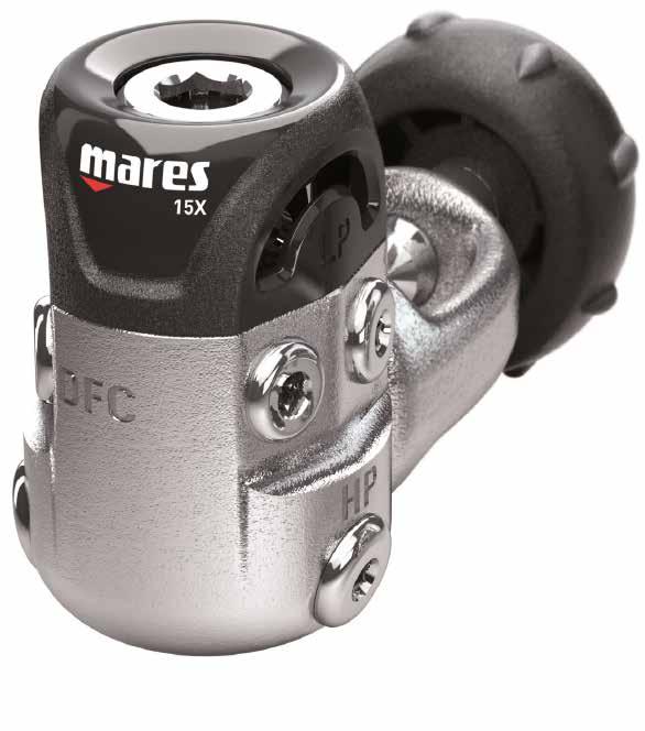
44 15X FIRST STAGE 15X FIRST STAGE

. AS SHOWN IN PIC.")
45 revised 2015 Technical Information ITM 37 ITM 37 PARBAK BACKUP RING FEB. 24, 2015 WITH REFERENCE TO PREVIOUS ITM 24_R1, MARES TECHNICAL SERVICE IS PLEASED TO INFORM ALL MARES LAB PARTNERS THAT AFTER HAVING PERFORMED SEVERAL TESTS, PART NUMBER PARBAK BACKUP RING WILL BE ASSEMBLED AS RUNNING CHANGE IN ALL NX REGULATORS AND VITON FIRST STAGE SERVICE KIT, STARTING FROM SEASON THE TESTS PERFORMED SHOW THAT PARBAK BACKUP RING PROVIDES EXCELLENT PERFORMANCE EVEN USED WITH NX FIRST STAGES, ESPECIALLY DIVING IN EXTREMELY COLD WATER (<= 0 C). AS SHOWN IN PIC. 1, THE PARBAK BACKUP RING CAN BE EASILY IDENTIFIED, THANKS TO THE BLACK COLOR OF THE NEW MATERIAL. -BACKUP RINGS CURRENTLY IN USE - -HP CHAMBER BACKUP RING, PARBAK- FIG. 1 FIG SIDE - A SIDE - B 5 ASSEMBLY INSTRUCTIONS MAKE SURE THAT ONCE INSERTED INTO THE BALANCING CHAMBER (4) THE BACKUP RING (5) HAS SIDE A (FIG. 2) FACING THE O-RING (6). WARNING! MAINTENANCE PROCEDURES MUST BE PERFORMED BY QUALIFIED PERSONNEL AT A MARESLAB TECHNICAL ASSISTANCE CENTER AND/OR AUTHORIZED MARES DISTRIBUTOR. IN ORDER TO DISASSEMBLE AND REASSEMBLE THE SEAT FROM THE FIRST STAGE, IT IS NECESSARY TO CONSULT THE PROCEDURES DESCRIBED IN THE RELATED SECTION OF THE MARES MAINTENANCE MANUAL. IN THE EVENT THAT THE UPDATED MANUAL, CONTAINING THE INDICATED SECTIONS IS UNAVAILABLE, OR IF THE INSTRUCTIONS ARE UNCLEAR OR NOT ENTIRELY UNDERSTANDABLE, PLEASE CONTACT MARES BEFORE PERFORMING ANY MAINTENANCE, ADJUSTMENT, OR CHECK.
46 revised 2015 Technical Information ITM 40 ITM 40 ACT (Advanced Coating Technology) FIRST STAGE POPPET INFO OCT. 08, 2015 MARES TECHNICAL DEPARTMENT IS PLEASED TO INFORM YOU THE NEW ACT POPPET (# ) IS CURRENTLY ASSEMBLED ON ALL INLINE DIAPHRAGM FIRST STAGES WITH THE EXCEPTION OF THE ABYSS NAVY II. THERE WILL BE NO CHANGES MADE TO IT AT THIS TIME. (SEE BTM 24) THE REGULATOR MATERIAL NUMBERS WILL STAY THE SAME. THE REGULATORS ASSEMBLED WITH THE NEW ACT POPPET, WILL BE EASILY IDENTIFIED BY AN X PRINTED ON THE CARDBOARD BOX AND ALSO PLACED ON THE FIRST STAGE PLASTIC PROTECTION COVER. EXAMPLE: ABYSS 22 = ABYSS 22X THE MAIN FEATURES OF THE ACT POPPET ARE: MADE OF TWO MATERIALS: CHROME PLATED BRASS LESS FRICTION OF THE STEM ACT COATING PROCESS EFFECTIVE SEPTEMBER 2015, ALL 1ST STAGE SERVICE KITS INCLUDE THE ACT POPPET, EXCEPT FOR THE ABYSS 22 NAVY II SERVICE KITS (INT: # / DIN: # ) DUE TO US NAVY PROTOCOLS. FIRST STAGE 52X-22X-15X INT/DIN: # FIRST STAGE 52X-22X-15X INT/DIN VITON: # FIRST STAGE 12S INT/DIN: # FIRST STAGE 12S INT/DIN VITON: # : SOME SERVICE KITS ARE USED FOR MULTIPLE FIRST STAGE MODELS. (I.E. KIT # (EXCLUDES POPPET) IS USED FOR THE 22, MR16, AND MR32). THESE SERVICE KITS WILL CONTINUE UNTIL THE CURRENT STOCK IS EXHAUSTED. AT THAT TIME, IT WILL BE REPLACED BY SERVICE KITS THAT WILL INCLUDE THE ACT POPPET. CHECK WITH MARES HQ FOR DETAILS). : THE CURRENT MR UPGRADE KIT (# ) WILL BE DISCONTINUED AND REPLACED BY THE ACT UPGRADE KIT (# ). VALVE SEAT CODE# (RO.15) IS NO LONGER AVAILABLE AND HAS BEEN REPLACED WITH THE VALVE SEAT CODE# (RO.05) IN THE SPARE PARTS CATALOG. MARES TECHNICAL DEPARTMENT SUGGESTS THE USE OF THE NEW VALVE SEAT CODE# IN ORDER TO PRODUCE OPTIMUM PERFORMANCE OF THE ACT FIRST STAGE POPPET, PARTICULARLY IN DIN (300 BAR) FIRST STAGES. IMPORTANT ALL SERVICE AND REPAIR PROCEDURES ON MARES PRODUCTS SHOULD BE PERFORMED BY QUALIFIED MARES SERVICE TECHNICIANS AT AUTHORIZED MARES SERVICE CENTER. SERVICE TECHNICIANS SHOULD HAVE THE LATEST VERSION OF THE MARES SERVICE MANUAL AND SPARE PART CATALOG READILY AVAILABLE WHILE PERFORMING SERVICE PROCEDURES AND CLOSELY FOLLOW THE RECOMMENDED PROCEDURES AND GUIDELINE OUTLINED IN THESE MATERIALS.
47 revised 2015 Technical Bulletin BTM25_R1 BTM 25_R1 REGULATOR SERVICE GUIDELINE AND SERVICE INTERVALS OCT. 27, 2015 Mares has revised the regulator service guidelines and service intervals. The new guidelines and intervals apply to all in-line Mares diaphragm regulators as of September 1st 2015, except for the Abyss 22 NAVY II regulator and octopus as noted below. MARES REGULATOR SERVICE GUIDELINES AND SERVICE INTERVALS PERFORM AN ANNUAL INSPECTION AND/OR SERVICE EVERY YEAR OR 100 DIVES The Mares annual regulator inspection and/or service is performed by following the procedures and guidelines outlined on the annual inspection and/or service checklist (see attached). The results of the inspection may require a complete regulator overhaul. A COMPLETE REGULATOR OVERHAUL MUST BE PERFORMED EVERY TWO YEARS OR 200 DIVES A complete regulator overhaul must be performed per specifications every two years as outlined in the Mares Service Manual. This requires, at minimum, replacing all parts included in the service kit. Please see the annual regulator inspection and/or service checklist for details. MARES ABYSS 22 NAVY II REGULATOR AND OCTOPUS SERVICE PROCEDURES AND INTERVALS Service procedures and intervals for the Abyss 22 Navy II Regulator and Octopus are different than those described above due to US Navy testing protocols. Below are the Service Guidelines for the Abyss 22 Navy II Regulator and Octopus: Every Year or 100 Hours of use: Mares recommends a complete overhaul every year or 100 hours of use. Mares recommends the 1st Stage Tri-material Poppet be replaced every two years or 200 hours of use, OR when signs of wear are present. The ACT Poppet (Code # ) SHOULD NOT BE USED in the Abyss 22 Navy II 1st Stage. Abyss 22 Navy II Service Guidelines REQUIRE the use of the Tri-material Poppet (Code # ) in the 1st stage in order to conform to US Navy testing protocols. The Tri-material Poppet is NOT included in the Abyss 22 Navy II 1st Stage Service Kit. When ordering Abyss 22 Navy II 1st Stage service kits, please order the Tri-material Poppet as a separate line item. IMPORTANT All service and repair procedures on Mares products should performed by qualified Mares Service Technicians at authorized Mares Dealers and Service Centers. Service Technicians should have the Mares Service Manual and Spare Parts Catalog readily available for reference while performing service procedures and closely follow the recommended procedures and guidelines outlined in these materials.
48 revised 2015 ANNUAL REGULATOR INSPECTION CHECKLIST OCT. 27, 2015 Date.../.../...Make / Model... Serial #... Customer Name... Purchase Date... /.../... TEST 1 Inspect Filter Pass Fail Check for debris or discoloration. TEST 2 Inspect HP Chamber area Pass Fail Inspect for dirty, rust, or corrosion. TEST 3 Hose Inspection Pass Fail Pull back hose protectors. Check that the hoses are secure in the hose crimp. TEST 4 Inspect 2 nd Stage Exhaust Valve Pass Fail Check valve and sealing surface for cleanliness, shape, and seal. TEST 5 Inspect Mouthpiece Pass Fail Inspect for tears, cracks or holes. Replace if necessary. TEST 6 2nd Stage Diaphragm Inspection Pass Fail Attempt inhalation without pressurization. Check for perfect seal. TEST 7 Intermediate Pressure Check Pass Fail Check for stable IP. IP must be within acceptable range per Service manual. TEST 8 Cracking Effort Pass Fail Check CE. CE must be within acceptable range per Service Manual. TEST 9 Pressurized Immersion test Pass Fail Pressurize and immerse unit. Test for any leaks. IMPORTANT 1. If the regulator fails Checklist Item 1, 2 or 9: A complete Regulator Overhaul is required 2. If the regulator fails Checklist Item 7 or 8: If the regulator can be adjusted within specifi ation, it passes. If not, a Complete Overhaul is required 3. If the regulator fails Checklist Item 3, 4, 5,or 6: The defective parts associated with the Checklist Item may be replaced, OR A Complete Regulator Overhaul maybe performed IMPORTANT All service and repair procedures on Mares products should performed by qualified Mares Service Technicians at authorized Mares Dealers and Service Centers. Service Technicians should have the Mares Service Manual and Spare Parts Catalog readily available for reference while performing service procedures and closely follow the recommended procedures and guidelines outlined in these materials.
49 revised X First Stage F1 15X. REQUIRED TOOLS AND SUPPLIES Tool Description #Code Tool Description #Code B-18 (14mm) B-4 (5mm) B-1 (25mm) B-13 (10mm) Hex 4mm No code Snap Ring Pliers (B14) B B B-17 (17mm) B B O-Ring removal tool Compressed air supply circuit or tank ( PSI/ bar) Compressed air gun ( PSI/8-10 bar) Ultrasonic cleaner & Descaling solution (e.g. Deox Extra type) or similar Loctite 415 or similar Test Bench (#416920) or Intermediate Pressure Gauge ( ) Christo-Lube MCG 111 Lubrication Technology or equal Neoprene Workpad (449822) First Stage service kit # INT / DIN - # INT / DIN Viton Nylon brush

 BEFORE BEGINNING DISASSEMBLY-REASSEMBLY-ADJUST. 3.a 1.")
, by turning it a little bit right and left. 3.b 4.")
 and O-rings (12) from the HP plugs (39). 6.")
 in a bench vise (if available) to hold the First Stage during")
, unscrew the HP chamber (11), remove the Spring (8), the First")
, and Washer (7) from the HP Chamber (11). 9.")
50 revised X First Stage F2 15X. DISASSEMBLY WARNING! IF THE FIRST STAGE IS USED TO DIVE WITH OXYGEN-ENRICHED MIXTURES, STRICTLY FOLLOW ALL THE INSTRUCTION PROVIDED IN THE MAINTENANCE MANUAL, IN THE NITROX CHAPTER (EN FOR EUROPEAN COUNTRY) BEFORE BEGINNING DISASSEMBLY-REASSEMBLY-ADJUST. 3.a 1. Loosen the Dust Cap (33 INT- 28 DIN) from the First stage. 2. Remove the Second Stage Hose using the 14mm wrench (B18). 3. Remove the First Stage Protection Cap (46), by turning it a little bit right and left. 3.b 4. Remove all LP plugs (40) and HP plugs (39) using a 4mm Allen wrench. 5. Remove the O-rings 13 form the LP plugs (39) and O-rings (12) from the HP plugs (39). 6. Insert the threaded bar Tool (B5) to a First Stage stage LP port. Place the threaded bar tool (B5) in a bench vise (if available) to hold the First Stage during the disassembly. 7. Using a 6mm Allen wrench (B-8), unscrew the HP chamber (11), remove the Spring (8), the First Stage Valve (5), and the Pin 26,5mm (1) from the First Stage Remove the O-ring (10), and Washer (7) from the HP Chamber (11). 9. Extract the O-ring (9) and the Backup Ring (3) from the HP Chamber (11), using an o-ring removal Tool made in plastic or brass. WARNING! DO NOT USE SHARP OR POINTED TOOLS MADE OF STEEL OR OTHER MATERIALS, TO AVOID SCRATCHING THE SURFACES OF THE HP CHAMBER b
, using a 10mm Allen wrench (B13) and remove the First Stage Diaphragm Spring (17) and the Spring Base Plate (16). 11.")
 and the Antifriction Ring (47) following one of the two steps described below: Option a Insert the nozzle (#415724) of a low pressure compressed air gun into the")

. Remove the Tool (B-6) from the HP chamber, and gently press the Pin with the plastic end of tool (B-41) to dislodge and remove the Poppet Button and Diaphragm. WARNING!")
51 revised X First Stage F3 15X. DISASSEMBLY 10. Flip the First Stage over as shown in the picture. Unscrew the Regulating Nut (19), using a 10mm Allen wrench (B13) and remove the First Stage Diaphragm Spring (17) and the Spring Base Plate (16). 11. Unscrew the Retaining Nut (18) using a 25mm Allen wrench (B1). 10.a 12. Remove the First Stage Diaphragm (15) and the Antifriction Ring (47) following one of the two steps described below: Option a Insert the nozzle (#415724) of a low pressure compressed air gun into the First stage HP chamber. Use short bursts of low pressure air to dislodge the Diaphragm (15). Once the Diaphragm is dislodged, remove it and the Poppet Button (14). Be sure that all LP & HP plugs are assembled on First Stage. 10.b Option b Place the First Stage on a flat surface with the Diaphragm side facing down. Position the special Tool (B6) inside the First Stage HP chamber and let the Poppet Pin (1) falling down through the tool and the HP Seat (2), so that it stays in its original position, in the First Stage button (14). Remove the Tool (B-6) from the HP chamber, and gently press the Pin with the plastic end of tool (B-41) to dislodge and remove the Poppet Button and Diaphragm. WARNING! DO NOT USE SHARP OR POINTED TOOLS TO REMOVE THE DIAPHRAGM. SCRATCHES ON THE SURFACES OF THE DIAPHRAGM MAY CAUSE HP LEAKING. If the Antifriction Ring (47) is still in its Seat after having completed step 12, remove it paying attention not to damage the First Stage Body. WARNING! DO NOT USE SHARP OR POINTED TOOLS TO REMOVE THE ANTIFRICTION RING (47). TO AVOID DAMAGING THE DIAPHRAGM. Option b 13. Insert the special Tool (B42) in the center hole of the First Stage Body (4) and remove the HP Seat (2). 14. Remove the O-ring (20) from the HP Seat (2). 13
52 revised X First Stage F4 15X. DISASSEMBLY INT (Section 15) DIN/Nitrox (Section 16)
 using the special Tool 25mm (B1) and remove the Yoke assembly (29-30-31-32). 15.")
 from the Yoke Retainer Nut (29). 15.1 WARNING!")
 from the Body Din Connector (24 35 NX), using a 4mm Allen wrench. 16.")
 from the Body Din connector (24 35 NX), by turning the First Stage Body upside down. 16.")
53 revised X First Stage F5 15X. DISASSEMBLY INT 15.1 Unscrew the Yoke Retainer Nut (29) using the special Tool 25mm (B1) and remove the Yoke assembly ( ) Disassemble the Retaining Ring (32) using the snap ring pliers (B14) and remove the Filter (30) and the Spring Filter (31) Remove the O-ring (10) from the Yoke Retainer Nut (29) WARNING! BE CAREFUL TO AVOID DAMAGING THE CHROME PLATING ON THE NUT YOKE RETAINER (23) WHEN DISASSEMBLING. 15X. DISASSEMBLY DIN - NX Unscrew the O-ring Seat (27 38 NX) from the Body Din Connector (24 35 NX), using a 4mm Allen wrench Remove the O-ring (26 37 NX) from the O-ring Seat (27 38 NX) Remove the Conical Filter (25 30 NX) from the Body Din connector (24 35 NX), by turning the First Stage Body upside down Insert a 5mm Allen wrench (B4) inside the Body Din Connector (24-35 NX) and unscrew it completely. To make this step easier, a wrench (as shown in the picture) can help Remove the O-ring (10) from the Body Din Connector (24 35 NX)
54 revised X First Stage F6 15X. INSPECTION AND CLEANING Reusable Rubber and Plastic Components Inspection Inspect all reusable rubber and plastic components for excessive wear and/or damage. Replace parts as necessary. Cleaning Clean all rubber and plastic components by washing them in a mixture of warm water and mild detergent. If necessary, scrub parts with a soft brush. Do not use abrasive cleaners, solvents or acids on rubber components. WARNING! SOLVENTS AND ACIDS MAY DAMAGE PLASTIC AND RUBBER PARTS. BEFORE CLEANING METAL COMPONENTS, MAKE SURE THAT ALL RUBBER AND PLASTIC PARTS HAVE BEEN REMOVED. Metal Components Inspection Inspect all parts for excessive wear and/or damage. Replace parts as necessary. Cleaning Chrome plated, brass, and stainless steel parts are cleaned by immersing them in an ultrasonic cleaner containing a de-scaling agent such as Deox Extra or a solution of white vinegar diluted with hot water. A nylon brush may be used to remove any stubborn deposits. Be sure to rinse all parts in fresh water and allow to completely dry before proceeding with reassembly.
 and are identified in the RED BOXES above.")
55 revised X First Stage F7 15X. FIRST STAGE SERVICE KIT Certain key components of the First Stage should be replaced during the overhaul. These key parts are included in the 15X First Stage Service Kit (Code INT/DIN NX) and are identified in the RED BOXES above. SERVICE KIT # INT / DIN NX

56 revised X First Stage F8 15X. REASSEMBLY Lubrication reduces the likelihood of damage during reassembly. Before beginning the reassembly procedure, lightly lubricate all O-rings with a high quality silicone grease. 17. Install the o-ring (20) on the HP Seat (2), and position the Seat on the special Tool (B21). 18. Insert the HP Seat (2) into the First Stage Body and gently press until the Seat is properly seated. WARNING! TAKE SPECIAL CARE NOT TO DAMAGE THE SEAT WHEN INSERTING IT. IT IS CORRECTLY SEATED IF THE CONICAL SECTION IS VISIBLE WHEN VIEWING IT FROM THE HIGH PRESSURE CHAMBER Correctly position the Backup Ring (3) and the O-ring (9) into the HP Chamber (11). WARNING! MAKE SURE THAT SIDE A OF THE BACK UP RING (3) IS FACING THE O-RING (9), AND SIDE B IS FACING THE BOTTOM OF THE HP CHAMBER (11). 20. Install the O-ring (10), and the Washer (7) on the HP Chamber (11). 21. Insert the First Stage valve (5) inside the First Stage Body, with the flat part facing the Valve Seat (2) Position the spring (8) on the First Stage valve (5) and tighten the HP chamber (11) using a 6mm Allen wrench (B4). SIDE - A SIDE - B
 and insert the First Stage pin 26,5mm (1) in the center hole of the")
 on the First Stage Pin (1) and press it down to feel the response of the Spring (8).")
 on the First Stage Diaphragm.")
 on the Diaphragm (15). 27.")
 to fully tighten the retaining nut to the First Stage Body.")
57 revised X First Stage F9 15X. REASSEMBLY 23. Flip the First Stage Body over (as shown in the picture) and insert the First Stage pin 26,5mm (1) in the center hole of the Body. 24. Position the First Stage valve button (14) on the First Stage Pin (1) and press it down to feel the response of the Spring (8). 25. Place the Diaphragm (15) in the First Stage Body, making sure is firmly seated in the Body. 23 Note the impression of the Poppet Button (14) on the First Stage Diaphragm. When re-installing the Diaphragm (15), be sure to install it facing the same direction as disassembled. 26. Correctly position the Antifriction Ring (47) on the Diaphragm (15). 27. Place the Spring Base Plate (16) in the middle of the Diaphragm (15). Use a 25-mm wrench (B1) to fully tighten the retaining nut to the First Stage Body. 25 If Using a Torque Wrench to tighten the Retaining Nut (17), use a tightening torque of 25 Nm / 18 ft*lbf. 28. Place the Spring (17) on the Spring Base Plate (14) Using the 10mm Allen wrench (B13), Install the Regulating Nut (196) making 3 4 turns of the wrench only. Do not over-tighten the Regulating Nut. Doing so can cause an increase in Intermediate Pressure, which can damage the LP Gauge and interfere with the IP adjustment procedure
 DIN/Nitrox (Section")
58 revised X First Stage F10 15X. REASSEMBLY INT (Section 30) DIN/Nitrox (Section 31)
, press down to fit the Retaining Ring (32) above the Filter (30) and in the Yoke Retainer Nut (29).")
 on the Yoke Retainer Nut (29). 30.5 Install the Yoke Knob (22) on the Yoke (21). Place the Yoke (21) on the First Stage Body. 30.6 Using a 25mm wrench (B1), fully tighten the Yoke Retainer Nut (29).")
59 revised X First Stage F11 15X. REASSEMBLY INT 30.1 Rotate the First Stage as shown in the picture Assemble the Filter Spring (31) and the Filter (30) in the Yoke Retainer Nut (29) Using the Retaining Ring pliers (B14), press down to fit the Retaining Ring (32) above the Filter (30) and in the Yoke Retainer Nut (29). The Retaining ring should be positioned with the sharp side up and rounded side down. Once installed, rotate the Retaining Ring to ensure it is correctly positioned Install the O-ring (10) on the Yoke Retainer Nut (29) Install the Yoke Knob (22) on the Yoke (21). Place the Yoke (21) on the First Stage Body Using a 25mm wrench (B1), fully tighten the Yoke Retainer Nut (29) If using a Torque Wrench, tighten to a torque of approximately ft*lbf / Nm. WARNING! TO PREVENT THE YOKE RETAINER NUT (7) FROM LOOSENING, APPLY ONE OR TWO DROPS OF THREAD LOCKING COMPOUND ONTO THE THREADS PRIOR TO INSTALLATION. REMOVE ANY RESIDUAL THREAD LOCKING COMPOUND PRIOR TO APPLYING ANY NEW COMPOUND (LOCTITE415 OR SIMILAR) Install the O-rings (12) on the HP plugs (39), and the O-rings (13) on the LP plugs (40) Install all HP and LP plugs on the First Stage Body, leaving the DFC and one additional LP port open for the Second Stage and IP Gauge.
 into the Threaded Locking ring (23 34 NX). 31.")
, tighten the Body DIN Connector (24 35 NX) to the First Stage body. WARNING!")
. 31.1-31.")
 in the Body Din Connector (24 35 NX). 31.5 Place the O-ring (26 37 NX) on the Din O-ring Seat (27 38 NX).")
60 revised X First Stage F12 15X. REASSEMBLY DIN - NX 31.1 Insert the Body DIN Connector (24 35 NX) into the Threaded Locking ring (23 34 NX) Position the O-ring (10) on the Body Din Connector (24 35 NX) Using a 5-mm Allen wrench (B 4), tighten the Body DIN Connector (24 35 NX) to the First Stage body. WARNING! TO PREVENT THE BODY DIN CONNECTOR (24) FROM LOOSENING, APPLY ONE OR TWO DROPS OF THREAD LOCKING COMPOUND ONTO THE THREADS PRIOR TO INSTALLATION. REMOVE ANY RESIDUAL THREAD LOCKING COMPOUND PRIOR TO APPLYING ANY NEW COMPOUND (LOCTITE 415 OR SIMILAR) If using a Torque Wrench, tighten to a torque of approximately 15 ft*lbs / 20 Nm Insert the Conical Filter (25 30 NX) in the Body Din Connector (24 35 NX) Place the O-ring (26 37 NX) on the Din O-ring Seat (27 38 NX) Using a 4mm Allen wrench, tighten the Din O-ring Seat (27 38 NX) to the Body Din Connector (24 35 NX). If using a Torque Wrench, tighten to a torque of approximately ft*lbs / 1,5-2 Nm Remove the Threaded Bar Tool (B-5) from the First Stage Body. Install O-Rings (12 13) on all HP and LP Port Plugs (39-40). 31.6
 on the HP plugs (39), and the O-rings (13) on the LP plugs (40). 31.")
 or test bench, and open the air valve slowly to expel any foreign matter from the fi st stage. 32.")
61 revised X First Stage F13 15X. REASSEMBLY DIN - NX 31.8 Install the O-rings (12) on the HP plugs (39), and the O-rings (13) on the LP plugs (40) Install all HP and LP plugs on the First Stage Body, leaving the DFC and one additional LP port open for the Second Stage and IP Gauge. 15X. ADJUSTMENT Connect the First Stage to a full tank (at least 2600 psi/180 bar) or test bench, and open the air valve slowly to expel any foreign matter from the fi st stage. 32. Attach the intermediate pressure gauge (# ) or connect the LP hose from the LP port of a Test Bench to the open low pressure port. 33. Attach the Second Stage hose to the port marked DFC (without the 2nd Stage cover installed). If using a Torque Wrench, tighten hoses to a torque of ft*lbs / 4-4,5 Nm.
62 revised X First Stage F14 15X. ADJUSTMENT TABLE 1: IP ADJUSTABLE RANGE HP Air Supply Intermediate Pressure (IP) 2900 psi psi 200 bar bar 34 Holding down the Second Stage Demand Lever, slowly open the tank valve and, almost simultaneously, release the Demand Lever. Read the value of the First Stage adjustment on the pressure gauge, and proceed as follows: IP No Second Stage free or intermittent air fl w can occur during the IP adjustment procedure. If any such fl w occurs, it will compromise the process and could cause the IP setting to be outside the acceptable range If the intermediate pressure is greater than the specified value (see table 1), use the 10mm Hex Wrench (B-13) to slowly loosen the Regulating Nut (19) until the specified value is obtained. HP WARNING! WHEN THE INTERMEDIATE PRESSURE IS REDUCED, IT IS NECESSARY TO VENT THE EXCESS AIR IN ORDER TO OBTAIN A CORRECT READING OF THE NEW VALUE If the First Stage pressure is lower than the specified value (see table 1), slowly tighten the Adjusting Nut (19) until the specified value is obtained. Once the intermediate pressure has been correctly set, operate the Second Stage demand lever two to three times to make sure the intermediate pressure remains constant for a few minutes The Second Stage adjustment procedures may now be performed. 34.2
63 revised X First Stage F15 15X. TROUBLESHOOTING Problem Probable Cause Solution 1. Intermediate Pressure too high Readjust IP per procedures CONTINUOUS AIR FLOW FROM SECOND STAGE (FREE FLOW) CAUSED BY: 1. AN INCREASE IN THE INTERMEDIATE PRESSURE, or 2. A CONTINUALLY INCREASING IP (IP CREEP) AIR LEAKS FROM FIRST STAGE DIAPHRAGM AIR LEAKS FROM THE FIRST STAGE HP/LP PORT PLUGS AND/OR HOSE PORTS AIR LEAKS BETWEEN YOKE NUT RETAINER AND TANK VALVE 2. Damaged First Stage Tri-material Poppet Replace Tri-material Poppet 2. Damaged Poppet Seat Replace Poppet Seat 2. Damaged HP Housing Assembly components or damaged HP Chanber Lose Locking Nut First Stage Diaphragm damaged First Stage diaphragm seating surface damaged Damaged O-ring corrosion on metal surface Lose hose and/or port plug O-ring seal of tank valve corroded or damaged Yoke Nut (7) sealing surface damaged O-Ring (71) damaged Check internal surfaces of HP Chamber. Clean or replace HP Chamber. Replace O-ring and/or Back Up Ring. Tighten CWD Kit Body Replace the Diaphragm Replace the First Stage Body Clean the Seat and/or replace O-ring Tighten hose and/or plug Clean the Seat of the tank valve and replace the O-ring Replace Yoke Nut Replace O-ring
64 revised X First Stage F16 15X. DRAWING E119 Updated: 03/12/2015
65 revised X First Stage F17 15X. CHART 42 Updated: 10/01/2017 CHART NO: 42 FIRST STAGE 15X UPDATED: 10/01/2017 REF CODE DESCRIPTION REF CODE DESCRIPTION PIN 26, OR HP SEAT MR 38 N O-RING SEAT NITROX (EN13949) BACKUP RING PK HP PLUG 7/16, FIRST STAGE 4 F FIRST STAGE BODY LP PLUG 3/8, FIRST STAGE, REGS FIRST STAGE POPPET ACT 41 C CWD DRY PISTON WASHER, HP CHAMBER 42 C PLASTIC RING CWD DRY SPRING, FIRST STAGE VALVE 43 C CWD DRY BODY, OR DIAPHRAGM, CWD KIT OR C HOCK CUP CWD DRY HP CHAMBER PROTECTION CAP 15X OR ANTI-FRICTION RING OR BUTTON FIRST STAGE POPPET DIAPHRAGM ASSEMBLIES PLATE SPRING BASE, FIRST STAGE DIN CONNECTOR 300 BAR ( ) SPRING DIAPHRAGM FIRST STAGE C KIT CWD DRY ( ) LOCKING NUT F FIRST STAGE 15X ASSEMBLY (INT-DIN) REGULATING NUT, FIRST STAGE SERVICE KIT FIRST STAGE 52X/22X/15X INT/DIN OR YOKE K11 NITROX VERSION YOKE KNOB N NITROX CONNECTOR 200 BAR (EN13949) - NBR ORINGS DIN 300 BAR THREADED LOCKING RING SERVICE KIT NX 1ST 52/22 (EN13949) - NBR ORINGS BODY, DIN CONNECTOR 300 BAR CONICAL FILTER, DIN OR O-RING SEAT, DIN PROTECTION CAP DIN NUT,YOKE RETAINER CONICAL FILTER, INT SPRING, FILTER FIRST STAGE RETAINING RING, FIRST STAGE FILTER DUST CAP INT Parts highlighted in red are included in the service kits N NITROX LOCKING RING 200 Bar (EN13949) As far as the first stages made before X series (2015), you can get the codes of the service kit Viton, Nitrox connector (Viton) and Service kit NX 35 N BODY, NITROX CONNECTOR 200 BAR (EN13949) (Viton) in the previous Spare Part catalogue (2015 and before) or in the YELLOW DUST CAP, NITROX Accessories 1 section of this Spare Part Catalogue

66 2S FIRST STAGE 2S FIRST STAGE
67 revised S First Stage F1 2S. REQUIRED TOOLS AND SUPPLIES Tool Description #Code Tool Description #Code B B B B-25 (25mm) Hex 4mm No code B-18 (14mm) B O-ring removal Tool Compressed diver grade air supply circuit or tank ( PSI/ bar) Compressed air gun ( PSI/8-10 bar) Ultrasonic cleaner & Descaling solution (e.g. Deox Extra type) or similar Test Bench (#416920) or Intermediate Pressure Gauge ( ) Silicone grease (Bluesil Vacuum GRS- Bluestar Silicones or Christo-Lube MCG 111 Lubrification Technology or equal) Loctite 415 or similar Neoprene Workpad (449822) First Stage service kit # INT / DIN INT / DIN Viton Nylon brush Bench vise Flat screwdriver (Usag 326 PH 0) or similar Torque Wrench


 from the First Stage and remove the Yoke Knob (22). 2. Remove the Second Stage hose using the 14mm wrench (B18).")
 by hand, use a flat sc ewdriver. 4.")
 in a bench vise to hold the First stage during the disassembly.")
, if present. 4 There should be no more than two washers present.")
 from the First Stage Cap (19). 7.")
68 revised S First Stage F2 2S. DISASSEMBLY WARNING IF THE FIRST STAGE IS USED TO DIVE WITH OXYGEN-ENRICHED MIXTURES, IT MUST BE O2 CLEANED. MARES RECOMMENDS O2 CLEANING USING THE PROCEDURES OUTLINED IN THE MARES O2 CLEANING GUIDELINES, AND FOLLOWING THE DISASSEMBLY/ REASSEMBLY/ADJUST PROCEDURES OUTLINED IN THIS MANUAL. OXYGEN ENRICHED MIXTURES IS DEFINED IN THE US AS OVER 40% O2. IN EU COUNTRIES IT IS DEFINED IN THE EN NORM. 1. Loosen the Dust Cap (10 INT- 28 DIN) from the First Stage and remove the Yoke Knob (22). 2. Remove the Second Stage hose using the 14mm wrench (B18) Remove the Cover (9) by twisting and pulling it. If difficulty is en ountered removing the Cover (9) by hand, use a flat sc ewdriver. 4. Insert the threaded bar Tool (B5) to a First Stage stage 3/8 LP port. 4 For best results, place the threaded bar Tool (B5) in a bench vise to hold the First stage during the disassembly. 5. Unscrew the First Stage Cap (19) using the 1st Stage Cap Wrench (23), and remove the Spring (4) and the Plastic Washers (27), if present. 4 There should be no more than two washers present. If more than two washers are present, you may need to replace the Spring to achieve the proper IP Value. 6. Remove the Piston assembly ( ) from the First Stage Cap (19). 7. Remove the Plastic Seat (3) from the Piston (18) using the HP Seat removal Tool (B-22). 8. Remove the O-rings (20) and (17) from the Piston (18). 6 s 9. Disassemble the Lp plugs (6) and the HP plug (14) using a 4mm Allen Wrench. 10. Remove the O-rings (5) from the Lp plugs (6) and the O-ring (13) from the HP plug (14). 6 b 7 a 7 b
69 revised S First Stage F3 2S. DISASSEMBLY INT (section 11) DIN (section 12)
 using the special Tool 25mm")
 using the snap ring pliers")
 from the Yoke Retainer Nut (23). 11.1 a 11.")
 from the Body DIN Connector")
 from the O-ring Seat (15). 12.")
, by turning the First Stage over. 11.2 b 12.")
 and unscrew it completely.")
70 revised S First Stage F4 2S. DISASSEMBLY 11.1 Unscrew the Yoke Retainer Nut (23) using the special Tool 25mm (B1) and remove the Yoke Retainer assembly ( ) Disassemble the Retaining Ring (2) using the snap ring pliers (B14) and remove the Filter (8) and the Spring Filter (12) Remove the O-ring (26) from the Yoke Retainer Nut (23) a 11.1 b 2S. DISASSEMBLY DIN 11.2 a 12.1 Unscrew the O-ring Seat DIN (15) from the Body DIN Connector (24) with a 4 mm Allen wrench Remove the O-ring (25) from the O-ring Seat (15) Remove the Sintered Filter (7) from the Body DIN Connector (24), by turning the First Stage over b 12.4 Insert a 5 mm Allen wrench (B4) inside the Body DIN Connector (24) and unscrew it completely. To make this step easier, a wrench (as shown in the picture) can help Remove the O-ring (26) from the Body Din Connector (24)
71 revised S First Stage F5 2S. INSPECTION AND CLEANING Reusable Rubber and Plastic Components Inspection Inspect all reusable rubber and plastic components for excessive wear and/or damage. Replace parts as necessary. Cleaning Clean all rubber and plastic components by washing them in a mixture of warm water and mild detergent. If necessary, scrub parts with a soft brush. Do not use abrasive cleaners, solvents or acids on rubber components. CAUTION SOLVENTS AND ACIDS MAY DAMAGE PLASTIC AND RUBBER PARTS. BEFORE CLEANING METAL COMPONENTS, MAKE SURE THAT ALL RUBBER AND PLASTIC PARTS HAVE BEEN REMOVED. Metal Components Inspection Inspect all parts for excessive wear and/or damage. Replace parts as necessary. Cleaning Chrome plated, brass, and stainless steel parts are cleaned by immersing them in an ultrasonic cleaner containing a de-scaling agent such as Deox Extra or a solution of white vinegar diluted with hot water. A nylon brush may be used to remove any stubborn deposits. Be sure to rinse all parts in fresh water and allow to completely dry before proceeding with reassembly.

72 revised S First Stage F6 2S. FIRST STAGE SERVICE KIT NUT YOKE RETAINER SPRING FILTER FILTER INT HP PLUG OR 108 LP PLUG OR 106 RETAINER RING PLASTIC SEAT OR ST BODY YOKE YOKE KNOB OR 2050 COVER 1 STAGE CAP OR 2100 PISTON SPRING POPPET 1 STAGE OR 3043 O-ring SEAT DIN FILTER DIN BODY DIN THREADED LOCK. RING Certain key components of the First Stage should be replaced during the overhaul. These key parts are included in the 2S First Stage Service Kit (Code INT/DIN INT/DIN Viton) and are identified in the RED BOXES above. SERVICE KIT # (INT/DIN) (INT/DIN) Viton

 into an LP port of the 1st Stage Body.")
 on the Piston (18). 15. Place the O-rings (20) and (17) on the Piston (18). 16.")
 is present, place it on the base of the Piston (18). 17.")
 is present, place it on top of the Spring (4).")
.")
73 revised S First Stage F7 2S. REASSEMBLY Lubrication reduces the likelihood of damage during reassembly. Before beginning the reassembly procedure, lightly lubricate all O-rings with Bluesil Vacuum GRS- Bluestar Silicones or Christo-Lube MCG 111 Lubrifi ation Technology or equal silicone grease Install the First Stage Disassembly Tool (B-5) into an LP port of the 1st Stage Body. For best results, place the threaded bar Tool (B5) in a bench vise to hold the First stage during the reasassembly Install a new Plastic Seat (3) on the Piston (18). 15. Place the O-rings (20) and (17) on the Piston (18). 16. Place the Piston assembly ( ) into the First Stage Cap (19). If one Washer (27) is present, place it on the base of the Piston (18). 17. Slightly lubricate the base of the Spring (4), and place it on the Piston (18), inside the First Stage Cap (19). If the second Washer (27) is present, place it on top of the Spring (4). 17 CAUTION THE NUMBER OF WASHERS TO INCREASE IP IS LIMITED TO TWO (2) MAXIMUM (ONE BETWEEN THE PISTON AND SPRING AND ONE BETWEEN THE SPRING AND 1ST STAGE BODY). IF THE MAXIMUM NUMBER OF WASHER HAVE BEEN INSTALLED AND THE IP VALUE IS BELOW THE RECOMMENDED IP RANGE, THE 1ST STAGE SPRING MUST BE REPLACED. 18. Install the Cap First Stage (19) with all the components ( ) assembled, on the First Stage Body (1), using the First Stage Cap Wrench (23). 19. Flip the First Stage over. 18
 DIN/Nitrox")
74 revised S First Stage F8 2S. REASSEMBLY INT (section 20) DIN/Nitrox (section 21)
 and the Filter (8) in the Yoke Retainer Nut (23). 20.")
. 20.")

 on the 1st Stage Body. 20.")
, USE A TIGHTENING TORQUE OF 13-15 ft *lbf /")
 FROM LOOSENING, APPLY ONE DROP OF THREAD LOCKING COMPOUND")
75 revised S First Stage F9 2S. REASSEMBLY 20.1 Assemble the Filter Spring (12) and the Filter (8) in the Yoke Retainer Nut (23) Using the retaining ring pliers (B14), press down to fit the Retaining Ring (2) above the Filter (8) in the Yoke Retainer Nut (23) a The Retaining ring should be positioned with the sharp side up and rounded side down. Once installed, rotate the Retaining Ring to ensure it is correctly positioned Install the O-ring (26) on the Yoke Retainer Nut (23) b 20.4 Install the Yoke Knob (22) on the Yoke (21). Place the Yoke (21+22) on the 1st Stage Body Using a 25mm wrench (B1), fully tighten the Yoke Retainer Nut (23). WARNING USE A TORQUE WRENCH TO TIGHTEN THE CWD DRY BODY (18), USE A TIGHTENING TORQUE OF ft *lbf / Nm 20.2 a DANGER TO PREVENT THE YOKE RETAINER NUT (7) FROM LOOSENING, APPLY ONE DROP OF THREAD LOCKING COMPOUND ONTO THE FIRST TWO THREADS PRIOR TO INSTALLATION. REMOVE ANY RESIDUAL THREAD LOCKING COMPOUND PRIOR TO APPLYING ANY NEW COMPOUND (LOCTITE 415 OR SIMILAR) b 20.6 Install the O-ring (13) on the HP plug (14), and the O-rings (5) on the LP plugs (6) Install all HP and LP plugs on the First Stage Body, leaving the DFC and one additional LP port open for the Second Stage and IP Gauge. 20.5
 into the Threaded Locking ring (11). 21.")
, tighten the Body DIN Connector (24) to the First Stage Body.")


 to the Body Din Connector (24).")
76 revised S First Stage F10 2S. REASSEMBLY DIN 21.1 Insert the Body DIN Connector (24) into the Threaded Locking ring (11) Position the O-ring (26) on the Body Din Connector (24) Using a 5-mm Allen wrench (B 4), tighten the Body DIN Connector (24) to the First Stage Body. DANGER TO PREVENT THE BODY DIN CONNECTOR (24) FROM LOOSENING, APPLY ONE DROP OF THREAD LOCKING COMPOUND ONTO THE FIRST TWO THREADS PRIOR TO INSTALLATION. REMOVE ANY RESIDUAL THREAD LOCKING COMPOUND PRIOR TO APPLYING ANY NEW COMPOUND (LOCTITE 415 OR SIMILAR) WARNING USE A TORQUE WRENCH TO TIGHTEN TO A TORQUE OF 15 ft*lbs / 20 Nm 21.4 Insert the Conical Filter (7) in the Body Din Connector (24) Place the O-ring (25) on the Din O-ring Seat (15) Using a 4mm Allen wrench, tighten the Din O-ring Seat (15) to the Body Din Connector (24). WARNING USE A TORQUE WRENCH TO TIGHTEN TO A TORQUE OF ft*lbs / 1,5-2 Nm Remove the Threaded Bar Tool (B-5) from the 1st Stage Body Install the O-ring (13) on the HP plugs (14), and the O-rings (5) on the LP plugs (6) Install all HP and LP plugs on the First Stage Body, leaving the DFC and one additional LP port open for the Second Stage and IP Gauge. 21.6
 or test bench, and open the air valve slowly to expel any foreign matter from the First Stage. 22.")
. IP WARNING USE A TORQUE WRENCH, TIGHTEN HOSES TO A TORQUE OF 3-3.")
77 revised S First Stage F11 2S. ADJUSTMENT Connect the First Stage to a full tank (at least 2600 psi/180 bar) or test bench, and open the air valve slowly to expel any foreign matter from the First Stage. 22. Attach the intermediate pressure gauge (# ) or connect the LP hose from the LP port of a Test Bench to the open low pressure port. 23. Attach the Second Stage hose to the port marked DFC (without the Second Stage cover installed). IP WARNING USE A TORQUE WRENCH, TIGHTEN HOSES TO A TORQUE OF ft*lbs / 4-4,5 Nm TABLE 1: IP ADJUSTABLE RANGE HP Air Supply Intermediate Pressure (IP) 2900 psi psi 500 psi /- 7 psi HP 24. Holding down the Second Stage demand lever, slowly open the tank valve and, almost simultaneously, release the demand lever. Read the value of the First Stage adjustment on the pressure gauge, and proceed as follows: No Second Stage free or intermittent air fl w from the 2nd stage should occur during the IP adjustment procedure. If any such fl w occurs, it will compromise the procedure and could cause the IP setting to be outside the acceptable range.
. 25.3 Reassemble the regulator as described in steps 13 to 18. 25.4 Proceed as described in steps 23 and 24 to check the Intermediate pressure.")
78 revised S First Stage F12 2S. ADJUSTMENT 25. If the First Stage intermediate pressure is greater than specified value (see table 1): 25.1 Disassemble the regulator from the tank and proceed as described in steps 1 to Remove one Plastic Washer (27) Reassemble the regulator as described in steps 13 to Proceed as described in steps 23 and 24 to check the Intermediate pressure. If there are no Plastic Washers present, and the IP is above the acceptable range, the Spring must be replaced. CAUTION WHEN THE INTERMEDIATE PRESSURE IS REDUCED, IT IS NECESSARY TO VENT THE EXCESS AIR IN ORDER TO OBTAIN A CORRECT READING OF THE NEW VALUE. 26. If the First Stage intermediate pressure is lower than specified value (see table 1): 26.1 Disassemble the regulator from the tank and proceed as described in steps 1 to Add one or two Plastic Washers (27) as described in step 16 and Reassemble the regulator as described in step 13 to Proceed as described in steps 23 and 24 to check the Intermediate pressure. CAUTION IF THERE ARE NO PLASTIC WASHERS PRESENT, AND THE IP IS ABOVE THE ACCEPTABLE RANGE, THE SPRING MUST BE REPLACED. Once the intermediate pressure has been correctly set, operate the Second Stage demand lever two to three times to make sure the intermediate pressure remains constant for a few minutes. The Second Stage adjustment procedures may now be performed. 26. Install the Cover (9).
79 revised S First Stage F13 2S. TROUBLESHOOTING Problem Probable Cause Solution 1. Intermediate Pressure too high Readjust IP per procedures CONTINUOUS AIR FLOW FROM SECOND STAGE (FREE FLOW) CAUSED BY: 1. AN INCREASE IN THE INTERMEDIATE PRESSURE, or 2. A CONTINUALLY INCREASING IP (IP CREEP) AIR LEAKS FROM FIRST STAGE DIAPHRAGM AIR LEAKS FROM THE FIRST STAGE HP/LP PORT PLUGS AND/OR HOSE PORTS AIR LEAKS BETWEEN YOKE AND TANK VALVE 2. Damaged First Stage Tri-material Poppet Replace Tri-material Poppet 2. Damaged Poppet Seat Replace Poppet Seat 2. Damaged HP Housing Assembly components or damaged HP Chanber Lose Locking Nut First Stage diaphragm damaged First Stage diaphragm seating surface damaged Damaged O-ring corrosion on metal surface Loose hose and/or port plug O-ring seal of tank valve corroded or damaged First stage Body (11) sealing surface damaged O-ring (71) damaged Check internal surfaces of HP Chamber. Clean or replace HP Chamber. Replace O-ring and/or Back Up Ring. Tighten CWD Kit Body Replace the diaphragm Replace the First Stage Body Clean the Seat and/or replace O-ring Tighten hose and/or plug Clean the Seat of the tank valve and replace the O-ring Replace First Stage Body (INT) Replace O-ring
80 revised S First Stage F14 2S. DRAWING E 976 Updated: 04/03/2016
81 revised S First Stage F15 2S. CHART 38 Updated: 10/01/2017 CHART NO: 38 1st STAGE R2S UPDATED: 10/01/2017 REF CODE DESCRIPTION REF CODE DESCRIPTION 1 C FIRST STAGE BODY OR RETAINING RING, FIRST STAGE FILTER PLASTIC RING, SPRING BASE PLASTIC SEAT, PISTON PROTECTION CAP DIN SPRING POPPET FIRST STAGE METAL THREADED LOCKING RING DIN NX 200 BAR OR BODY DIN CONNECTOR BAR LP PLUG 3/8", FIRST STAGE, REGS OR CONICAL FILTER, DIN O-RING SEAT DIN NX CONICAL FILTER, INT YELLOW DUST CAP, NITROX COVER METAL THREADED LOCKING RING DIN DUST CAP, INT DIN 300 BAR THREADED LOCKING RING ASSEMBLIES SPRING, FILTER 1ST C FIRST STAGE R2S ASSEMBLY (INT-DIN) OR 108 F DIN CONNECTOR 300 BAR, R2S ( ) HP PLUG 7/16", FIRST STAGE SERVICE KIT FIRST STAGE R2S INT/DIN O-RING SEAT DIN OR 2018 NITROX VERSION PISTON FIRST STAGE N NITROX CONNECTOR 200 BAR (EN13949) - NBR ORINGS CAP FIRST STAGE SERVICE KIT NX 1ST 52/22 (EN13949) - NBR ORINGS OR YOKE 2k9 Parts highlighted in red are included in the service kits YOKE KNOB As far as the first stages made before X series (2015) are concerned, NUT,YOKE RETAINER FIRST STAGE R2S you can get the codes of the Viton service kits, Nitrox connector (Viton) and Service kit NX (Viton) in the previous Spare Part catalogues ( BODY, DIN CONNECTOR 300 BAR and before) or in the Accessories 1 section of the present Spare Part OR 3043 Catalogue.
82 revised S First Stage F16 2S. DRAWING E 976 Updated: 04/03/2016
83 revised S First Stage F17 2S. CHART 44 Updated: 10/01/2017 CHART NO: 44 1st STAGE R2S - XR UPDATED: 10/01/2017 REF CODE DESCRIPTION REF CODE DESCRIPTION 1 C FIRST STAGE BODY OR RETAINING RING, FIRST STAGE FILTER OR PLASTIC SEAT, PISTON PLASTIC RING, SPRING BASE SPRING POPPET FIRST STAGE PROTECTION CAP DIN OR METAL THREADED LOCKING RING DIN NX 200 BAR LP PLUG 3/8", FIRST STAGE, REGS BODY DIN CONNECTOR BAR CONICAL FILTER, DIN OR CONICAL FILTER, INT O-RING SEAT DIN NX COVER YELLOW DUST CAP, NITROX COVER NX METAL THREADED LOCKING RING DIN DUST CAP, INT ASSEMBLIES DIN 300 BAR THREADED LOCKING RING SERVICE KIT FIRST STAGE R2S INT/DIN SPRING, FILTER 1ST OR HP PLUG 7/16", FIRST STAGE O-RING SEAT DIN NITROX VERSION OR 2018 N NITROX CONNECTOR 200 BAR (EN13949) - NBR ORINGS PISTON FIRST STAGE SERVICE KIT NX 1ST 52/22 (EN13949) - NBR ORINGS CAP FIRST STAGE OR 2100 Parts highlighted in red are included in the service kits YOKE 2k9 As far as the first stages made before X series (2015) are concerned, YOKE KNOB you can get the codes of the Viton service kits, Nitrox connector (Viton) and Service kit NX (Viton) in the previous Spare Part catalogues ( NUT,YOKE RETAINER FIRST STAGE R2S and before) or in the Accessories 1 section of the present Spare Part BODY, DIN CONNECTOR 300 BAR Catalogue
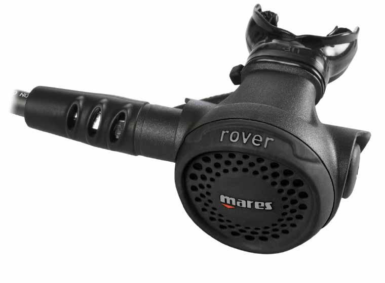
84 ROVER SECOND STAGE ROVER SECOND STAGE

85 revised 2017 Technical Information ITM 23 ITM 23 INSERT DEMAND LEVER # JUL. 18, 2011 MARES S.p.A. TECHNICAL SUPPORT WISHES TO NOTIFY MARES LAB CENTERS AND TECHNICIANS OF A CHANGE MADE TO THE METAL INSERT DEMAND LEVER (# ) USED IN PRESTIGE, PRESTIGE DPD, ROVER, AND CARBON SECOND STAGES. THE NEW VERSION MAKES THE SECOND STAGE LIGHTER WEIGHT AND DELIVERS IMPROVED BREATHING COMFORT. THE CHANGE MADE WAS TO THE OVERMOULDING OF THE NYLON INSERT, AND CAN BE IDENTIFIED BY THE BLACK COLOR AS SHOWN IN THE PHOTO FOUND IN THE TECHNICAL INFORMATION. THE NEW OVERMOULDED DEMAND LEVER WILL REPLACE THE PREVIOUS VERSION, WHICH WILL BE AVAILABLE WHILE SUPPLIES LAST AND CAN BE REQUESTED AS A SPARE PART USING CODE: # INITIALLY THE REGULATORS ON WHICH THE NEW INSERT DEMAND LEVER WILL BE ASSEMBLED CAN BE RECOGNIZED BY A SERIAL NUMBER AS SHOWN IN THE FOLLOWING TABLE: PRODUCT CODE DESCRIPTION SERIAL NUMBER PRESTIGE 12S DIN SM OCTOPUS PRESTIGE SMU STE PRESTIGE 12S INT SMU STD OCTOPUS PRESTIGE PO ROVER 2S INT RS ROVER OCTOPUS RH STAGE DEMAND LEVER INSERT # # WARNING! MAINTENANCE OPERATIONS MUST BE PERFORMED BY QUALIFIED PERSONNEL AT A MARES TECHNICAL ASSISTANCE CENTER AND/OR AUTHORIZED MARES DISTRIBUTOR. IN ORDER TO DISASSEMBLE AND REASSEMBLE THE SEAT FROM THE FIRST STAGE, IT IS NECESSARY TO CONSULT THE PROCEDURES DESCRIBED IN THE CORRESPONDING SECTION OF THE MAINTENANCE MANUAL (S-11). IF THE UPDATED MANUAL CONTAINING THESE SECTIONS IS NOT AVAILABLE AND/OR IF THE INSTRUCTIONS ARE NOT CLEAR OR FULLY UNDERSTANDABLE, PLEASE CONTACT MARES S.p.A. TECHNICAL SUPPORT BEFORE PERFORMING ANY MAINTENANCE, ADJUSTMENT, OR INSPECTION OPERATIONS.

86 revised 2017 Technical Information ITM 33 ITM 33 INSERT DEMAND LEVER # NOV. 05, 2013 TECHNICAL ASSISTANCE DEPT. WISH TO INFORM THAT, AFTER RECEIVING SOME CLAIMS FROM THE MARKET ABOUT BLACK SPOTS ON ROVER & ROVER OCTOPUS COVERS AND/ORA FEW CRACKS DUE TO PARTICULAR CONDITION OF USE AND/OR STORAGE, WE TESTED AND APPROVED A NEW MATERIAL IN ORDER TO AVOID THESE ISSUES. THE NEW COVERS ARE NOW AVAILABLE AND CAN BE ORDERED AS SPARE PARTS, USING THE FOLLOWING CODES THAT REPLACE THE PREVIOUS ONES : Rover Cover Second stage Black : Rover Cover Octopus Yellow : Rover Cover Nitrox Green IN ADDITION, YOU CAN ALSO EASILY IDENTIFY THE VERSIONS WITH NEW MATERIAL, THANKS TO 3 SMALL LINES, AS SHOWED IN THE PICTURE: - NEW ROVER COVER - WARNING! MAINTENANCE OPERATIONS MUST BE PERFORMED BY QUALIFIED PERSONNEL AT A MARES TECHNICAL ASSISTANCE CENTER AND/OR AUTHORIZED MARES DISTRIBUTOR. IN ORDER TO DISASSEMBLE AND REASSEMBLE THE SEAT FROM THE FIRST STAGE, IT IS NECESSARY TO CONSULT THE PROCEDURES DESCRIBED IN THE CORRESPONDING SECTION OF THE MAINTENANCE MANUAL (S-11). IF THE UPDATED MANUAL CONTAINING THESE SECTIONS IS NOT AVAILABLE AND/OR IF THE INSTRUCTIONS ARE NOT CLEAR OR FULLY UNDERSTANDABLE, PLEASE CONTACT MARES S.p.A. TECHNICAL SUPPORT BEFORE PERFORMING ANY MAINTENANCE, ADJUSTMENT, OR INSPECTION OPERATIONS
87 revised 2017 Rover Second Stage S1 ROVER. REQUIRED TOOLS AND SUPPLIES Tool Description #Code Tool Description #Code B B-18 (14mm) B B-4 (5mm) Hex 4mm No code B B B-8 (6mm) B-17 (17mm) O-Ring removal Tool Compressed air diver grade supply circuit or tank ( PSI/ bar) Compressed air gun ( PSI/8-10 bar) Ultrasonic cleaner & Descaling solution (e.g. Deox Extra type) or similar Magnehelic gauge (# #416924) Silicone grease (Bluesil Vacuum GRS- Bluestar Silicones or Christo-Lube MCG 111 Lubrification Technology or equal) Neoprene Workpad (449822) Second Stage service kit # # Viton Nylon brush Phillips screwdriver (Usag 326 PH 0) or similar Nippers Torque Wrench

, cut the Mouthpiece Clamp (43) and remove")

 from the Second stage. 7a 5.")
. 6.")
. 8. Unscrew the Cover (101). 7b 9.")
. 10.")
88 revised 2017 Rover Second Stage S2 ROVER. DISASSEMBLY 1. Remove the Dust Cap and move the hose cover from the 1st stage. Unscrew the hose (26) using a 14-mm open end wrench (B18). 2. Using cutting nippers (or pliers), cut the Mouthpiece Clamp (43) and remove the Mouthpiece (44). CAUTION TAKE SPECIAL CARE TO AVOID BREAKING THE MOUTHPIECE Remove the Exhaust Plug pin (174) and the Inspection Plug (41) using the B-22 tool. 4. Remove the Hose Protector (46) from the Second stage. 7a 5. Using two 17mm open end wrenches (B-17), remove the Hose (26) from the Second Stage Hose Connector (28). 6. Remove the O-rings (27 and 19) from each end of the Hose (26). 7. Remove the Pin Cover (63). 8. Unscrew the Cover (101). 7b 9. Remove the Diaphragm Retaining Ring (78) and the Diaphragm (36) from the Second Stage Case (32). 10. Unscrew the Hose Connector (28) using a 17-mm open end wrench (B-17), and pull out the By-pass Retainer Ring (96). 11. Gently press the Demand Lever Connector assembly into the case and remove the O-Ring (83) from its seat in the Second stage Case (32). 8a 8b 10 11
 to unscrew the Locknut (33) from the Demand Lever (35). Press down the Insert (91) to put pressure on the Poppet Spring (31) and relieve the tension on the Demand Lever Locknut (33).")
, and the Spring (31). After removing locknut, washer, and demand lever, slowly release the pressure on the poppet spring while covering it with your hand.")
, by gently pressing down the Valve Body (92) towards the threaded stem. 16. Disassemble the Valve Body (92) from the stem of the Second stage valve shaft (30). 17.")
89 revised 2017 Rover Second Stage S3 ROVER. DISASSEMBLY 12. Position the demand Lever Insert assembly on the special tool (B-6) and use the special 5.5mm wrench (B-12) to unscrew the Locknut (33) from the Demand Lever (35). Press down the Insert (91) to put pressure on the Poppet Spring (31) and relieve the tension on the Demand Lever Locknut (33). While continuing to press down, use the special 5.5mm wrench (B-12) to remove the Locknut (33); then remove the Washer (34), and the Demand Lever (35). B Remove the Poppet assembly ( ), and the Spring (31). After removing locknut, washer, and demand lever, slowly release the pressure on the poppet spring while covering it with your hand. This will prevent an uncontrolled exit by the spring from the second stage case. 14. Remove the Exhaust Valve (40). 15. Remove the Rubber Seat (47), by gently pressing down the Valve Body (92) towards the threaded stem. 16. Disassemble the Valve Body (92) from the stem of the Second stage valve shaft (30). 17. Unscrew the Poppet Seat (21) from the Hose Connector (28) using a 5-mm hex wrench (B-4). After 5 turns back, gently press the Poppet Seat (21) with the plastic end of tool (B-42) to dislodge and remove it B -6 CAUTION DO NOT USE SHARP OR POINTED TOOLS TO EXTRACT THE POPPET SEAT. SCRATCHES ON THE SEAT SURFACE MAY CAUSE AIR LEAKS
 using a 6-mm hex wrench (B-8) and remove the O-Rings (83). ROVER.")


90 revised 2017 Rover Second Stage S4 ROVER. DISASSEMBLY 18. Remove the O-Ring (71) from the hose connector (28) and the O-Ring (27) from the seat connector (21). 19. Unscrew the Second stage adj plug (64) using a 6-mm hex wrench (B-8) and remove the O-Rings (83). ROVER. INSPECTION AND CLEANING 18a Reusable Rubber and Plastic Components Inspection Inspect all reusable rubber and plastic components for excessive wear and/or damage. Replace parts as necessary. Cleaning Clean all rubber and plastic components by washing them in a mixture of warm water and mild detergent. If necessary, scrub parts with a soft brush. Do not use abrasive cleaners, solvents or acids on rubber components. 18b CAUTION SOLVENTS AND ACIDS MAY DAMAGE PLASTIC AND RUBBER PARTS. BEFORE CLEANING METAL COMPONENTS, MAKE SURE THAT ALL RUBBER AND PLASTIC PARTS HAVE BEEN REMOVED. 19 Metal Components Inspection Inspect all parts for excessive wear and/or damage. Replace parts as necessary. Cleaning Chrome plated, brass, and stainless steel parts are cleaned by immersing them in an ultrasonic cleaner containing a de-scaling agent such as Deox Extra or a solution of white vinegar diluted with hot water. A nylon brush may be used to remove any stubborn deposits. Be sure to rinse all parts in fresh water and allow to completely dry before proceeding with reassembly.
 and are identified in the RED BOXES below.")
91 revised 2017 Rover Second Stage S5 ROVER. SECOND STAGE SERVICE KIT Some key components of the Second Stage should be replaced during the overhaul. These key parts are included in the Prestige/Rover Second Stage Service Kit (Code ) and are identified in the RED BOXES below. SERVICE KIT #


 stem at approximately half it s length. 22.")
92 revised 2017 Rover Second Stage S6 ROVER. REASSEMBLY Lubrication reduces the likelihood of damage during reassembly. Before beginning the reassembly procedure, lightly lubricate all O-rings with Bluesil Vacuum GRS- Bluestar Silicones or Christo-Lube MCG 111 Lubrifi ation Technology or equal Carefully install a new Exhaust Valve (40) by gently pulling the silicone valve stem through the hole of the Second Stage exhaust valve opening. CAUTION IN ORDER TO AVOID DAMAGING THE EXHAUST VALVE, DO NOT PULL THE STEM TOO HARD Use cutting nippers to cut the end section of the Exhaust Valve (40) stem at approximately half it s length. 22. Reassemble the Poppet Body (92) on the Second Stage poppet stem (30). 23. Reassemble the Poppet Seat (47) in the Poppet Body (92). 24. Place the Second stage Poppet assembly ( ) together with its spring (31) on the special tool (B-6)
 and hold it in place, by gently press it.")
 in the groove of the demand lever insert (91) as shown in the pic 26. 27.")
 HEIGHT ADJUSTMENT REQUIRES THE USE OF SPECIAL TOOL B-12 (TYPE BETA 942BX5.5) OR A WRENCH WITH A HEAD DIAMETER OF NO MORE THAN 8.2 MM /0.32 INCH.")
93 revised 2017 Rover Second Stage S7 ROVER. REASSEMBLY 25. Correctly position the Second Stage valve and its spring into the demand lever insert (91) and hold it in place, by gently press it. To be sure that the Second Stage Poppet stem is correctly positioned into the demand lever connector hole, gently rotate the connector left and right on the B-6 tool. 26. Properly position the Demand Lever (35) in the groove of the demand lever insert (91) as shown in the pic Place the Washer (34) on the poppet stem and tighten the demand lever adjusting nut (33) 7 or 8 full turns using the special wrench (B-20). CAUTION DEMAND LEVER (35) HEIGHT ADJUSTMENT REQUIRES THE USE OF SPECIAL TOOL B-12 (TYPE BETA 942BX5.5) OR A WRENCH WITH A HEAD DIAMETER OF NO MORE THAN 8.2 MM /0.32 INCH. B Press the Demand Lever a few times to be sure it is able to move freely. CAUTION DO NOT OVER-TIGHTEN THE DEMAND LEVER LOCKNUT (33). DOING SO MAY RESULT IN A SECOND STAGE FREE FLOW, WHICH CAN INTERFERE WITH THE INTERMEDIATE PRESSURE ADJUSTMENT PROCEDURE. 27a 27b
 in the seat of the Hose Connector (28) and the O-ring (27) in the seat of the Poppet")
, screw the Poppet Seat (21) all the way into the Hose Connector (14) until it")
 the Poppet Seat 4 1/2 turns (main Second Stage) or until it extends about 2.")
 the Poppet Seat 4 turns (main Second Stage) or until it extends about 3mm")

94 revised 2017 Rover Second Stage S8 ROVER. REASSEMBLY 28. Install the O-Ring (71) in the seat of the Hose Connector (28) and the O-ring (27) in the seat of the Poppet Seat (21). 29. Using the 5mm hex wrench (B-4), screw the Poppet Seat (21) all the way into the Hose Connector (14) until it stops (Do not over tighten). Loosen (turn counter clockwise) the Poppet Seat 4 1/2 turns (main Second Stage) or until it extends about 2.5 mm from the hose connector (28). Loosen (turn counter clockwise) the Poppet Seat 4 turns (main Second Stage) or until it extends about 3mm (Octopus version) 28 CAUTION THE POPPET SEAT SETTING DESCRIBED IN STEP 29 IS AN INITIAL ADJUSTMENT ONLY, AND SHOULD BE RESET IF IT IS DETERMINED THE CRACKING EFFORT IS NOT WITHIN THE ACCEPTABLE RANGE. 30. Correctly place the Demand Lever insert assembly (91) in the Second Stage Case (32). 31. Hold the Demand Lever Insert in place into the Second Stage Case (32) with the B-20 Tool, install the O-Ring (83) into the seat between the Second Stage Case and the Demand Lever Insert, using the special Tool (B-6) a 31b
.")
 in the Second Stage end of the LP Hose (26) and the O-Ring (19) in the 1st Stage end of the Hose. 34.")
95 revised 2017 Rover Second Stage S9 ROVER. REASSEMBLY 32. Put the Spacer Ring (96) in place, and use the 17-mm open-end wrench (B-17) to tighten the Hose Connector (28) in the Second Stage Case. Press the demand lever few times. Place a small amount of silicone grease on the threads of the O-ring side of the Hose Connector (28). WARNING USE A TORQUE WRENCH TO TIGHTEN THE RETAINING NUT (17), USE A TIGHTENING TORQUE OF 6 ft*lbf / 8 Nm. 32 a 33. Install the O-ring (27) in the Second Stage end of the LP Hose (26) and the O-Ring (19) in the 1st Stage end of the Hose. 34. Using two wrenches (B-17), connect the Hose (26) to the Hose Connector (28). DANGER MAKE SURE THE HOSE CONNECTOR IS SECURELY TIGHTENED BEFORE CONNECTING THE HOSE PROTECTOR TO THE ADJUSTABLE VAD KNOB. FAILURE TO DO SO, MAY RESULT IN THE HOSE CONNECTOR DISCONNECTING FROM THE SECOND STAGE CASE DURING USE. 32 b 35. Connect the LP Hose (26) with the Second Stage attached (without the Second Stage cover installed) to the 1st Stage LP Port marked DFC. WARNING! IF USING A TORQUE WRENCH TO TIGHTEN THE LP HOSE, USE A TIGHTENING TORQUE OF ft*lbf / 4-4,5 Nm. 34 CAUTION AT THIS POINT, CONNECT THE SECOND STAGE TO THE FIRST STAGE AND SET THE FIRST STAGE INTERMEDIATE PRESSURE AS DESCRIBED IN THE FIRST STAGE SERVICE MANUAL.

 already assembly, and the Metal Disk in")
 with the plastic teeth facing")
 on the Second")
96 revised 2017 Rover Second Stage S10 ROVER. REASSEMBLY 36. Insert the Diaphragm (36) into the Second Stage Case with the Diaphragm Ring (78) already assembly, and the Metal Disk in contact with the Demand Lever. Place the Diaphragm Ring (78) with the plastic teeth facing up. 36a 37. Place and tighten the Second Stage cover (101) on the Second Stage case (32). Align the Pin Cover seat of the Second Stage cover(101) with the Pin Cover seat of the Second Stage case (32). 36b 37a 37b
. 38 39.")
 to properly adjust the Demand Lever (35).")
97 revised 2017 Rover Second Stage S11 ROVER. REASSEMBLY 38. Insert the Safety Clip (63). Then lock down the clip all the way down to the cover. CAUTION ALL THE ADJUSTMENTS BELOW MUST BE MADE WITH THE SECOND STAGE CONSISTENTLY SUPPLIED WITH THE CORRECT INTERMEDIATE PRESSURE (IP) Insert the B12 wrench through the adjusting hole in the Second Stage Case and secure it to the Demand Lever Locknut. Tighten or loosen the Demand Lever locknut (32) to properly adjust the Demand Lever (35). 39 CAUTION THE DEMAND LEVER IS ADJUSTED CORRECTLY WHEN THE LEVER IS SLIGHTLY LOOSE, AND AIR BEGINS TO FLOW WHEN THE PURGE BUTTON IS DEPRESSED ABOUT 2MM. A TAPPING SOUND OF THE DEMAND LEVER TOUCHING THE METAL DISK OF THE SECOND STAGE DIAPHRAGM SHOULD BE AUDIBLE WHEN THE PRESSURIZED SECOND STAGE IS SHAKEN VIGOROUSLY UP AND DOWN. 40. Press the purge button few times, and then install the O-Ring (83) on the Second Stage ADJ plug (64). 41. Use the hex wrench (B-8) to fully tighten the Second Stage ADJ Plug (64) assembly in the Second Stage Case (32).
98 revised 2017 Rover Second Stage S12 ROVER. ADJUSTMENT 42. Recheck the Intermediate Pressure ( bar/ psi). 43. Attach the Second Stage to a Magnehelic gauge. 44. Measure the Second Stage Cracking Effort. CAUTION THE CRACKING EFFORT MUST BE READ THE MOMENT THE INTERMEDIATE PRESSURE STARTS TO DECREASE. MAGNEHELIC GAUGE Magnehelic gauge Inches Magnehelic gauge cm Rover Rover Oct If the Cracking Effort is outside of the acceptable range, proceed as described below: 45.1 Move the Second Stage side hose protector (46). Using two wrenches (B-17), unscrew the hose (26) from the connection (28) If the Cracking Effort value is lower than the acceptable range, screw in the Poppet Seat (21), a ¼ turn at the time till the value is correct If the Cracking Effort value is higher than the acceptable range, unscrew the Poppet Seat (21), a ¼ turn at the time till the value is correct.
99 revised 2017 Rover Second Stage S13 ROVER. ADJUSTMENT 45.4 Using two wrenches (B-17), connect the LP Hose (26) to the Hose Connector (28) Put the hose protector (46) in place Measure the Second Stage Cracking Effort. Follow the steps described above until the acceptable cracking effort value is reached. 46. Shut off the HP air supply and purge all residual air. 47. Inhale directly from the Second Stage Mouthpiece in order to detect any air leakeage from inside of the Case. ROVER. REASSEMBLY 48. Assemble the Inspection Plug (41) on the second stage, and secure it with the Exhaust Plug pin (174). 49. Carefully assemble the Mouthpiece (44), securing it with a new Mouthpiece Clamp (43).
100 revised 2017 Rover Second Stage S14 ROVER. TROUBLESHOOTING Problem Probable Cause Solution Continuous or intermittent air flow from the Second Stage Cracking Pressure higher than acceptable range Rubber Seat (47) Damaged Sealing surface of the Poppet Seat (21) is dirty or damaged IP exceeds acceptable range Demand Lever set too high Poppet Spring (31) out of position or damaged Incorrect Poppet Seat (21) adjustment (too low) Demand Lever set too low IP outside of acceptable range Tank valve not fully opened Second Stage Poppet Spring deformed or damaged First Stage filter clogged Incorrect Poppet Seat (21) adjustment (too high) High Poppet Spring tension Replace Rubber Seat Clean or replace Poppet Seat Adjust IP to ( bar) ( psi) Or Cold Water Kit ( bar) ( psi) Adjust to correct height Position correctly or replace Adjust to 4 ½ Turns/2,5mm Adjust to correct height Adjust IP to ( ) Or Cold Water Kit ( ) Completely open the tank valve Replace Poppet Spring Overhaul First Stage and replace filter Adjust to 4 ½ Turns/2,5mm Replace Poppet Spring
101 revised 2017 Rover Second Stage S15 ROVER. TROUBLESHOOTING Problem Probable Cause Solution Cracking Pressure lower than acceptable range Traces of water inside Second Stage Vibration sound from Second Stage during inhalation IP outside of acceptable range Second Stage Poppet Spring deformed or damaged Demand Lever set too high Incorrect Poppet Seat (21) adjustment (too low) Ring Clamp (37) loose or damaged Exhaust Valve support dirty Exhaust Valve (40) damaged Diaphragm (36) dirty, damaged, or incorectly positioned Mouthpiece (44) loose or damaged Diaphragm (36) incorrectly positioned Incorrect Demand lever adjustment Poppet Spring (31) damaged or incorreclty positioned Adjust IP to ( bar) ( psi) Or Cold Water Kit ( bar) ( psi) Replace Poppet Spring Adjust to correct height Adjust to 4 ½ Turns/2,5mm Tighten or replace Clean support Replace Exhaust Valve Clean, position correctly or replace Replace the clamp; replace mouthpiece Check and position correctly Check and adjust correctly Check and Position correctly or replace
102 revised 2017 Rover Second Stage S16 ROVER. DRAWING E 38 Updated: 12/12/2008
103 revised 2017 Rover Second Stage S17 ROVER. CHART 128 Updated: 10/01/2017 CHART NO: 128 SECOND STAGE OCTOPUS ROVER UPDATED: 10/01/2017 REF CODE DESCRIPTION REF CODE DESCRIPTION OR OR POPPET SEAT DIAPHRAGM RING PRESTIGE LP HOSE 3/8 black 80 cm WO/HOSE PROTECTOR OR LP HOSE 3/8 yellow 100 cm WO/HOSE PROTECTOR INSERT FOR DEMAND LEVER OR VALVE BODY, SECOND STAGE HOSE CONNECTOR SPACER RING BY-PASS BK POPPET METAL BODY REGS SPACER RING BY-PASS YL SPRING SECOND STAGE COVER 2 nd STAGE Rover BLACK SECOND STAGE CASE COVER OCTOPUS Rover LOCKNUT, DEMAND LEVER COVER NITROX Rover WASHER, DEMAND LEVER EXHAUST PLUG PIN DEMAND LEVER DIAPHRAGM BLACK ASSEMBLIES EXHAUST VALVE, SECOND STAGE PACK BLACK MOUTHPIECES INSPECTION PLUG SERVICE KIT ROVER/PRESTIGE/CARBON/CR CLAMP KIT RETROFIT ( ) SEE CATALOGUE HOSE PROTECTOR HOSE PROTECTOR SECOND STAGE RUBBER SEAT SECOND STAGE Parts highlighted in red are included in the service kits PIN-COVER Service kit (Viton) is available in the Accessori 1 section until the stocks SECOND STAGE. ADJUSTMENT PLUG ends; it will be replaced by the Service kit with NBR O-rings
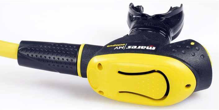
104 OCTOPUS MV OCTOPUS MV

")


105 revised 2017 Technical Bulletin BTM 20 BTM 20 OCTOPUS MV COVER JAN. 10, 2011 HAVING RECEIVED A NUMBER OF REPORTS, MARES SPA TECHNICAL SUPPORT REQUESTS THAT ALL MARES LAB PARTNERS, WHEN CARRYING OUT PERIODIC INSPECTIONS, CHECK FOR THE PRESENCE OF SMALL HOLES IN THE OVAL MEMBRANE OF THE SECOND STAGE (CODE: ) AROUND THE METAL DISK (PHOTO 1). IF ANY HOLES ARE DISCOVERED THE OVAL MEMBRANE MUST BE REPLACED AND YOU MUST CHECK THE SURFACE OF THE PURGE BUTTON POPPET (CODE: ) (PHOTO 2) TO CHECK FOR ANY RESIDUAL MATERIAL (PHOTO 3); IF SO REMOVE (PHOTO 4) USING A CUTTER FOR EXAMPLE, IN ORDER TO AVOID THE PROBLEM RETURNING WHEN REPLACING THE MEMBRANE. MARES SPA ALSO RECOMMENDS CHECKING ANY STOCK OF MV COVERS KEPT AS SPARE PARTS AND THEN REMOVE THE PLASTIC RIDGE IF NEEDED. PHOTO 1 PHOTO 2 PHOTO 3 PHOTO 4 WARNING THE OPERATIONS DESCRIBED MUST BE CARRIED OUT BY QUALIFIED PERSONNEL AT A TECHNICAL SUPPORT CENTRE AND/OR AUTHORISED MARES LAB DISTRIBUTOR.IN THE ABSENCE OF AN UP-TO-DATE MAINTENANCE MANUAL, PLEASE CONTACT MARES TECHNICAL SUPPORT BEFORE CARRYING OUT ANY MAINTENANCE AND/OR REPAIR, ADJUSTMENT AND INSPECTION.
: 1.")
 THE NEW EXHAUST VALVE IS SLIGHTLY HARDER THAN THE PREVIOUS VERSION (#46184006), THEREBY ENSURING A PERFECT SEAL EVEN WHEN THERE IS A CURRENT.")
106 revised 2017 Technical Information ITM 27 ITM 27 MV EXHAUST VALVE # NOV. 28, 2012 MARES S.p.A. TECHNICAL SUPPORT WISHES TO INFORM ALL MARES LAB CENTERS AND TECHNICIANS THAT THE FOLLOWING CHANGES WILL BE MADE TO THE MV SECOND STAGE/OCTOPUS CODE (416523): 1. NEW EXHAUST VALVE # (PHOTO 1 REF. A) 2. NEW EXHAUST TEE (# ) (PHOTO 2 REF. B) THE NEW EXHAUST VALVE IS SLIGHTLY HARDER THAN THE PREVIOUS VERSION (# ), THEREBY ENSURING A PERFECT SEAL EVEN WHEN THERE IS A CURRENT. IT WILL BE ASSEMBLED BEGINNING WITH THE SERIAL NUMBERS INDICATED BELOW, AND WILL BE EASILY DISTINGUISHABLE FROM THE PREVIOUS VERSION BY THE NEW COLOR (GREY) (PHOTO 1, REF. A). THANKS TO ITS NEW STREAMLINED SHAPE, THE NEW EXHAUST TEE AND THE INTERNAL BAFFLES (PHOTO 2 REF. B) IMPROVE BOTH APPEARANCE AND PERFORMANCE DURING THE EXHALE (AIR RELEASE). THE NEW TEE WILL BE ASSEMBLED WITH THE IN-LINE EXCHANGE SYSTEM AS SOON AS STOCK OF THE PREVIOUS VERSION IS EXHAUSTED (PHOTO 2 REF. A). THE REGULATORS ON WHICH THE NEW EXHAUST VALVE AND NEW TEE ARE ASSEMBLED CAN BE RECOGNIZED BY SERIAL NUMBER, AS SHOWN IN THE TABLE BELOW: PRODUCT CODE DESCRIPTION SERIAL NUMBER MV OCTOPUS BMD10001 WARNING MAINTENANCE OPERATIONS MUST BE PERFORMED BY QUALIFIED PERSONNEL AT A MARES TECHNICAL ASSISTANCE CENTER AND/OR AUTHORIZED MARES DISTRIBUTOR. IN ORDER TO DISASSEMBLE AND REASSEMBLE THE SEAT FROM THE FIRST STAGE, IT IS NECESSARY TO CONSULT THE PROCEDURES DESCRIBED IN THE CORRESPONDING SECTION OF THE MAINTENANCE MANUAL (S-11). IF THE UPDATED MANUAL CONTAINING THE REQUIRED SECTIONS IS NOT AVAILABLE AND/OR IF THE INSTRUCTIONS ARE NOT ENTIRELY CLEAR OR NOT FULLY COMPREHENSIBLE, PLEASE CONTACT THE MARES S.p.A. TECHNICAL SUPPORT SERVICE BEFORE CONDUCTING ANY MAINTENANCE, ADJUSTMENT, OR CONTROL OPERATIONS.
107 revised 2017 Octopus MV S1 MV. REQUIRED TOOLS AND SUPPLIES Tool Description #Code Tool Description #Code B B-18 (14mm) Hex 4mm No code B-4 (5mm) B Pliers (type Usag 133) B-17 (17mm) B O-ring removal Tool Compressed air diver grade supply circuit or tank ( PSI/ bar) Compressed air gun ( PSI/8-10 bar) Ultrasonic cleaner & Descaling solution (e.g. Deox Extra type) or similar Magnehelic gauge (# #416924) Silicone grease (Bluesil Vacuum GRS- Bluestar Silicones or Christo-Lube MCG 111 Lubrification Technology or equal) Neoprene Workpad (449822) Second Stage service kit # # Viton Nylon brush Phillips screwdriver (Usag 326 PH 0) or similar Nippers Torque Wrench
 from the Second Stage and using two wrenches (B-17), unscrew the Hose (26) from the Hose Connector (28). 2.")

, Metal washers (152) and Plastic Washers (151) from Cover (141). 4-5 6.")
108 revised 2017 Octopus MV S2 MV. DISASSEMBLY 1. Remove the Hose Protector (46) from the Second Stage and using two wrenches (B-17), unscrew the Hose (26) from the Hose Connector (28). 2. Remove the O-rings (27 and 19) from each end of the Hose (26). 3. Using cutting nippers (or pliers), cut the Mouthpiece Clamp (43) and remove the Mouthpiece (44). 1 CAUTION TAKE SPECIAL CARE TO AVOID DAMAGE TO THE MOUTHPIECE. 4. Use a small Phillips head screwdriver to unscrew the three Screws (140) that fasten the Cover (141). 5. Remove the Cover (141) and the Oval Diaphragm (142). We suggest you do not remove the screws (140), Metal washers (152) and Plastic Washers (151) from Cover (141) Unscrew the Hose Connector (28) using a 17-mm open end wrench (B-17), and then pull out the Lock Ring (96). 7. Gently press the Demand Lever Insert assembly (91) into the case and remove the O-Ring (83) from the Second Stage Case (32) using special Tool B-6 as shown. 6 B - 6 7
 on the special Tool (B-6) and use the special 5.")
 to put pressure on the Poppet Spring (31) and relieve the tension on the Demand Lever Locknut (33).")
 to remove the Locknut (33); then remove the Washer (34), and the Demand Lever (35). B - 12 9.")
 from the stem of the Second Stage Valve Shaft (30). 11.")
109 revised 2017 Octopus MV S3 MV. DISASSEMBLY 8. Position the Demand Lever insert assembly (91) on the special Tool (B-6) and use the special 5.5mm wrench (B-12) to unscrew the Locknut (33) from the Demand Lever (35). Press down the Insert (91) to put pressure on the Poppet Spring (31) and relieve the tension on the Demand Lever Locknut (33). While continuing to press down, use the special 5.5mm wrench (B-12) to remove the Locknut (33); then remove the Washer (34), and the Demand Lever (35). B Remove the Rubber Seat (47), by gently pressing down the Valve Body (92) towards threaded stem. 10. Disassemble the Poppet Seat Holder (92) from the stem of the Second Stage Valve Shaft (30). 11. Unscrew the Poppet Seat (21) from the Hose Connector (28) using a 5-mm hex wrench (B-4). After 5 turns back, gently press the Poppet Seat (21) with the plastic end of Tool (B-42) to dislodge and remove it. B CAUTION DO NOT USE SHARP OR POINTED TOOLS TO EXTRACT THE POPPET SEAT. SCRATCHES ON THE SEAT SURFACE MAY CAUSE AIR LEAKS. 9 11
,remove the Exhaust Valve Holder assembly (144). 14.")

110 revised 2017 Octopus MV S4 MV. DISASSEMBLY 12. Gently press the pins of the Exhaust Valve Grid (145), using a special Tool B-22, and remove it. B Gently pressing from the inside of the Second Stage Case (32),remove the Exhaust Valve Holder assembly (144). 14. Remove the Exhaust Valve (40) and the O-ring (143) from the Exhaust Valve Holder (144). MV. INSPECTION AND CLEANING Reusable Rubber and Plastic Components 12 Inspection Inspect all reusable rubber and plastic components for excessive wear and/or damage. Replace parts as necessary. Cleaning Clean all rubber and plastic components by washing them in a mixture of warm water and mild detergent. If necessary, scrub parts with a soft brush. Do not use abrasive cleaners, solvents or acids on rubber components. 13 CAUTION SOLVENTS AND ACIDS MAY DAMAGE PLASTIC AND RUBBER PARTS. BEFORE CLEANING METAL COMPONENTS, MAKE SURE THAT ALL RUBBER AND PLASTIC PARTS HAVE BEEN REMOVED. Metal Components Inspection Inspect all parts for excessive wear and/or damage. Replace parts as necessary. Cleaning Chrome plated, brass, and stainless steel parts are cleaned by immersing them in an ultrasonic cleaner containing a de-scaling agent such as Deox Extra or a solution of white vinegar diluted with hot water. A nylon brush may be used to remove any stubborn deposits. Be sure to rinse all parts in fresh water and allow to completely dry before proceeding with reassembly.

111 revised 2017 Octopus MV S5 MV. SECOND STAGE SERVICE KIT MOUTHPIECE VALVE BODY SPRING DEMAND LEVER 2 STAGE INSERT WASHER PLASTIC CLAMP RUBBER PAD POPPET BODY HOSE CONNECT. LEVER LOCKNUT 2 STAGE CASE EXHAUST VALVE SEAT POPPET SEAT OR 2025 OR 2050 LOCK RING OR 2068 OR 2025 OR 106 SCREW COVER NBS SPRING DIAPHRAGM OR 2068 EXHAUST VALVE LP HOSE WASHER COVER PLASTIC WASHER STICKER COVER EX. VALVE GRID Some key components of the Second Stage should be replaced at each scheduled overhaul. These key parts are included in the MV second Stage Service Kit (# ) and are identified in the RED BOXES below. SERVICE KIT #

 together with its spring (31) on the special Tool (B-6). 18.")

112 revised 2017 Octopus MV S6 MV. REASSEMBLY Lubrication reduces the likelihood of damage during reassembly. Before beginning the reassembly procedure, lightly lubricate all O-rings with Bluesil Vacuum GRS- Bluestar Silicones or Christo-Lube MCG 111 Lubrifi ation Technology or equal. 15. Reassemble the Valve Body (92) on the Second Stage Poppet Stem (30). 16. Reassemble the Rubber Pad (47) in the Valve Body (92). 17. Place the Second Stage Poppet assembly ( ) together with its spring (31) on the special Tool (B-6). 18. Pressing gently, correctly position the Second Stage Valve and its spring into the Demand Lever Connector (91) and hold it in place. To be sure that the Second Stage Poppet Stem is correctly positioned into the Demand Lever Connector hole, gently rotate the Connector left and right on the B-6 Tool Properly position the Demand Lever (35) in the groove of the Demand Lever Insert (91) as shown in the pic Place the Washer (34) on the Poppet Stem and tighten the Demand Lever Locknut (33) 7 or 8 full turns using the special wrench (B-20). CAUTION DEMAND LEVER (35) HEIGHT ADJUSTMENT REQUIRES THE USE OF SPECIAL TOOL B-12 (TYPE BETA 942BX5.5) OR A WRENCH WITH A HEAD DIAMETER OF NO MORE THAN 8.2 MM /0.32 INCH B Press the demand lever a few times to be sure it is able to move freely CAUTION DO NOT OVER-TIGHTEN THE DEMAND LEVER LOCKNUT (33). DOING SO MAY RESULT IN A SECOND STAGE FREE FLOW, WHICH CAN INTERFERE WITH THE INTERMEDIATE PRESSURE ADJUSTMENT PROCEDURE. 20
 on the Hose Connector (28) and the O-ring (27) on the Seat Connector")
, screw the Poppet Seat (21) all the way into the Hose")
 the Poppet Seat 3 ¾ turns or until it extends about 3.")

 in the Second Stage Case (32),")
113 revised 2017 Octopus MV S7 MV. REASSEMBLY 21. Install the O-Ring (71) on the Hose Connector (28) and the O-ring (27) on the Seat Connector (21). 22. Using the 5mm hex wrench (B-4), screw the Poppet Seat (21) all the way into the Hose Connector (28) until it stops (Do not over tighten). Loosen (turn counter clockwise) the Poppet Seat 3 ¾ turns or until it extends about 3.2 mm from the Hose Connector (28). CAUTION THE POPPET SEAT SETTING DESCRIBED IN STEP 22 IS AN INITIAL ADJUSTMENT ONLY, AND SHOULD BE RESET IF IT IS DETERMINED THE CRACKING EFFORT IS NOT WITHIN THE ACCEPTABLE RANGE Correctly place the Demand Lever Insert assembly (91) in the Second Stage Case (32), using wrench B Hold the Demand Lever Connector in place in the Second Stage Case as shown, insert the O-Ring (83) into the Seat between the Second Stage Case and the Demand Lever Connector using the special wrench (B-6) B a 24 b
.")
 in the Second Stage end of the LP Hose (26) and the O-Ring (19) in the First Stage end of the Hose. 27 27.")
114 revised 2017 Octopus MV S8 MV. REASSEMBLY 25. Put the Spacer Ring (96) in place, and use the 17-mm open-end wrench (B-17) to tighten the Hose Connector (28) in the second Stage Case. Press the Demand Lever a few times. Place a small amount of silicone grease on the threads of the O-ring side of the Hose Connector (28). 25 WARNING USE A TORQUE WRENCH TO TIGHTEN THE RETAINING NUT (17), USE A TIGHTENING TORQUE OF 6 ft*lbf / 8 Nm. 26. Install the O-ring (27) in the Second Stage end of the LP Hose (26) and the O-Ring (19) in the First Stage end of the Hose Using two wrenches (B-17), connect the Hose (26) to the Hose Connector (28). DANGER MAKE SURE THE HOSE CONNECTOR IS SECURELY TIGHTENED BEFORE CONNECTING THE LP HOSE. FAILURE TO DO SO, MAY RESULT IN THE HOSE CONNECTOR DISCONNECTING FROM THE SECOND STAGE CASE DURING USE. 28. Connect the LP Hose (26) with the Second Stage attached (without the second Stage cover installed) to the First Stage LP Port marked DFC. WARNING USE A TORQUE WRENCH TO TIGHTEN THE LP HOSE, USE A TIGHTENING TORQUE OF ft*lbf / 4-4,5 Nm. CAUTION AT THIS POINT, CONNECT THE SECOND STAGE TO THE FIRST STAGE AND SET THE FIRST STAGE INTERMEDIATE PRESSURE AS DESCRIBED IN THE FIRST STAGE SERVICE MANUAL.
 with the Diaphragm (142) on the Second Stage Case (32) and secure it with the Screws")


 by gently pulling the silicone valve stem through the hole of the")
115 revised 2017 Octopus MV S9 MV. REASSEMBLY 29. Place the Second Stage Diaphragm (142) into the Cover (141). 30. Place the Cover (141) with the Diaphragm (142) on the Second Stage Case (32) and secure it with the Screws (140). 31. Insert the B12 wrench through the adjusting hole in the Second Stage Case and secure it to the Demand Lever Locknut. Tighten or loosen the Demand Lever Locknut (32) to properly adjust the Demand Lever (35). CAUTION THE DEMAND LEVER IS ADJUSTED CORRECTLY WHEN THE LEVER IS SLIGHTLY LOOSE, AND AIR BEGINS TO FLOW WHEN THE PURGE BUTTON IS DEPRESSED ABOUT 2MM. A TAPPING SOUND OF THE DEMAND LEVER TOUCHING THE METAL DISK OF THE SECOND STAGE DIAPHRAGM SHOULD BE AUDIBLE WHEN THE PRESSURIZED SECOND STAGE IS SHAKEN VIGOROUSLY UP AND DOWN Carefully install a new Exhaust Valve (40) by gently pulling the silicone valve stem through the hole of the Second Stage Exhaust Valve Holder (144). CAUTION IN ORDER TO AVOID DAMAGING THE EXHAUST VALVE, DO NOT PULL THE STEM TOO HARD 33. Place the Exhaust Valve Holder (144) assembly in the Second Stage case (32) with the Exhaust Valve facing outward

116 revised 2017 Octopus MV S10 MV. ADJUSTMENT 34. Recheck Intermediate Pressure ( bar/ psi). MAGNEHELIC GAUGE 35. Attach the Second Stage to a Magnehelic Gauge. 36. Measure the Second Stage Cracking Effort. CAUTION THE CRACKING EFFORT MUST BE READ THE MOMENT THE INTERMEDIATE PRESSURE STARTS TO DECREASE. Magnehelic gauge Inches Magnehelic gauge cm Rover Oct If the Cracking Effort is outside of the acceptable range, proceed as described below: 37.1 Move the Second Stage side Hose Protector (46). Using two wrenches (B-17), unscrew the Hose (26) from the Hose Connector (28) If the Cracking Effort value is lower than the acceptable range, screw in the Poppet Seat (21), a ¼ turn at the time till the value is correct If the Cracking Effort value is higher than the acceptable range, unscrew the Poppet Seat (21), a ¼ turn at the time till the value is correct.

117 revised 2017 Octopus MV S11 MV. ADJUSTMENT 37.4 Using two wrenches (B-17), connect the LP Hose (15) to the Hose Connector (28) Put the Hose Protector (46) in place Measure the Second Stage Cracking Effort. Follow the steps described above until the acceptable cracking effort value is reached Shut off the HP air supply and purge all residual air. 39. Inhale directly from the Second Stage Mouthpiece in order to detect any air leakage from inside of the case. MV. FINAL ADJUSTMENT 40. Assemble the Exhaust Grid (145) on the support flange on the Second Stage. CAUTION MAKE SURE THAT BOTH PINS ARE LOCKED INTO THE CASE. 41. Carefully assemble the Mouthpiece (44), securing it with a new Mouthpiece Clamp (43).
118 revised 2017 Octopus MV S12 MV. TROUBLESHOOTING Problem Probable Cause Solution Continuous or intermittent air flow from the Second Stage Cracking Pressure higher than acceptable range Rubber Pad (47) Damaged Sealing surface of the Adj. Seat (21) is dirty or damaged IP exceeds acceptable range Demand Lever set too high Poppet Spring (31) out of position or damaged Incorrect Poppet Seat (21) adjustment (too low) NBS spring (166) missing Demand Lever set too low IP outside of acceptable range Tank valve not fully opened Second Stage Poppet Spring deformed or damaged First Stage filter clogged Incorrect Poppet Seat (21) adjustment (too high) High Poppet Spring tension Replace Rubber Seat Clean or replace Poppet Seat Adjust IP to ( bar) ( psi) Or Cold Water Kit ( bar) ( psi) Adjust to correct height Position correctly or replace Adjust to 3 ¾ Turns/3,2 mm Place it correctly Adjust to correct height Adjust IP to ( ) Or Cold Water Kit ( ) Completely open the tank valve Replace Poppet Spring Overhaul First Stage and replace filter Adjust to 3 ¾ Turns/3,2 mm Replace Poppet Spring
119 revised 2017 Octopus MV S13 MV. TROUBLESHOOTING Problem Probable Cause Solution Cracking Pressure lower than acceptable range Traces of water inside Second Stage Vibration sound from Second Stage during inhalation IP outside of acceptable range Second Stage Poppet Spring deformed or damaged Demand Lever set too high Incorrect Poppet Seat (21) adjustment (too low) Exhaust valve support back-to-front Exhaust Valve support dirty Exhaust Valve (40) damaged Diaphragm (36) dirty, damaged, or incorectly positioned Mouthpiece (44) loose or damaged Diaphragm (36) incorrectly positioned Incorrect Demand lever adjustment Poppet Spring (31) damaged or incorreclty positioned Adjust IP to ( bar) ( psi) Or Cold Water Kit ( bar) ( psi) Replace Poppet Spring Adjust to correct height Adjust to 3 ¾ Turns/3,2 mm Position it correctly Clean support Replace Exhaust Valve Clean, position correctly or replace Replace the clamp; replace mouthpiece Check and position correctly Check and adjust correctly Check and Position correctly or replace
120 revised 2017 Octopus MV S14 MV. DRAWING E 34 Updated: 21/11/2013
121 revised 2017 Octopus MV S15 MV. CHART 124 Updated: 10/01/2017 CHART NO: 124 OCTOPUS MV UPDATED: 10/01/2017 REF CODE DESCRIPTION REF CODE DESCRIPTION OR LOCK RING POPPET SEAT MARES OVAL LABEL - 17,5 mm LP HOSE 3/8 yellow 100 cm WO/HOSE PROTECTOR SCREW M 2X5 DIN 7985-A OR COVER MV YELLOW HOSE CONNECTOR OVAL DIAPHRAGM POPPET METAL BODY REGS O RING SPRING REGULATOR SECOND STAGE EXHAUST VALVE SEAT 32 SECOND STAGE CASE EXHAUST VALVE GRID BK LOCKNUT, DEMAND LEVER WHITE WASHER 1,8X5X0, WASHER DEMAND LEVER FLAT WASHER UNI 6592 D 4, DEMAND LEVER CONICAL SPRING EXHAUST VALVE MOUTHPIECE CLAMP ASSEMBLIES SEE CATALOGUE PACK BLACK MOUTHPIECES HOSE PROTECTOR SECOND STAGE CASE MV (32-166) HOSE PROTECTOR SECOND STAGE SERVICE KIT SECOND STAGE MV RUBBER SEAT SECOND STAGE KIT RETROFIT ( ) OCTOPUS PLUG OR OR 2068 Parts highlighted in red are included in the service kits POPPET HOUSING Service kit (Viton) is available in the Accessory 1 section until the stocks VALVE BODY SECOND STAGE ends; it will be replaced by the Service kit with NBR O-rings
122 ERGO LP INFLATOR ERGO LP INFLATOR
123 original copywriter 1987 revised printed 1999 ERGO LP INFLATOR B2-1 LP INFLATOR REMOVAL 1. Unscrew the rapid exhaust valve (RE) locking nut and remove the entire infl ator system from the BC. 2. Remove the gasket from the BC collar. DISASSEMBLY 1. Gently pry off the mouthpiece (61) (see numbered Ergo LP infl ator diagram) using a slotted screwdriver. 2. Press the power infl ate button (54). Insert a 1/8 pin punch into the small round hole near the manual quick disconnect (QD) fi tting, then push the pin (53) until it comes out completely (Fig. 1). 3. Remove the infl ate button (54) and 0-ring (55). 4. Remove 0-ring (55) from infl ate button (54). 5. Remove spring (48). 6. Remove the valve holder unit by inserting fl at-nose pliers into the notches of the valve holder (57). Pull the valve holder (57) straight out of the infl ator body (Fig. 2 and 3). 7. Remove the two 0-rings (58) from the valve holder. 8. With suitable pliers, cut clamp (59) and remove the corrugated hose (60) from the infl ator (46). By lightly clamping LP infl ator (46) in a vice with plastic jaws, use two small screwdrivers to depress the two tabs on the anchoring bushing (47), then remove the anchoring bushing from the infl ator body (Fig. 4). 9. Remove spring (48) from the anchoring bushing (47). 10. With special tool (P/N Fig. 5) or needle nose pliers, compress the defl ate button retaining tabs and remove defl ate button (52) from bushing (49) (Fig. 6). 11. Remove O-ring (50) from bushing (49). 12. Remove O-ring (5 1) from defl ate button (52). 13. Remove the male QD cap (27) from the male QD (13) and using a 14 mm hex wrench, unscrew the male QD connector. 14. Remove O-ring (9) from the connector. 15. Remove the fi lter (22) from the infl ator body. 16. Remove the male QD cap (27) and LP hose clip (62) from the corrugated hose (60) only if the male QD cap, LP hose clip or corrugated hose are to be replaced. 17. If the anchoring bushing (47), corrugated hose (60), RE valve plate (63) or actuating cable (66) are to be replaced, cut the cable near the anchoring bushing. Fig. 1 Fig. 2 Fig. 3 Fig. 4 ONCE THE ACTUATING CABLE HAS BEEN CUT IT MUST BE REPLACED. THE ACTUATING CABLE SHOULD BE CUT ONLY IF THE ANCHORING BUSHING (47), CORRUGATED HOSE (60), RE VALVE PLATE (63) OR ACTUATING CABLE (66) ARE TO REPLACED. Fig. 5
 and remove (Fig. 7). 21. Remove the exhaust diaphragm (6) and housing (7) from RE cap (69).")
 from the RE housing and unthread the actuating cable (66), detaching it from RE valve plate (63). 24. Remove spring (64) from RE housing. DISASSEMBLY RE VALVE 2K12 Fig.")
124 B2-2 ERGO LP INFLATOR original copywriter 1987 revised printed Remove anchoring bushing (47) from actuating cable (66). 19. With suitable pliers, cut clamp (59) and remove the corrugated hose (60) from the RE valve (F). 20. Unscrew the RE cap (69) and remove (Fig. 7). 21. Remove the exhaust diaphragm (6) and housing (7) from RE cap (69). IT IS NOT NECESSARY TO REMOVE THE EXHAUST DIAPHRAGM (6) FROM THE HOUSING (7), UNLESS THE EXHAUST DIAPHRAGM OR HOUSING ARE TO BE REPLACED. Fig Remove gasket (67) from RE housing. 23. Remove the RE valve plate (63) from the RE housing and unthread the actuating cable (66), detaching it from RE valve plate (63). 24. Remove spring (64) from RE housing. DISASSEMBLY RE VALVE 2K12 Fig. 7 I. With suitable pliers, cut clamps (59) and remove the corrugated hose (60) from the RE valve (32). II. Remove Spring Bearing(38) from RE valve body (32), using a small screwdriver. III. Take the Gasket (34) out. IV. Untie rope only in case Line(66) and/or Bushing (47) must be replace/s. Photo 1 Photo 2
125 original copywriter 1987 revised printed 1999 ERGO LP INFLATOR B2-3 CLEANING Cleaning requires all reusable rubber and plastic parts to be carefully cleaned by scrubbing with a soft brush in a mild detergent and water solution. Do not use solvents or acids on rubber or plastic parts. Metal parts should be cleaned in an ultrasonic cleaner with fresh water or a mild acid solution. (White vinegar diluted with warm water is recommended). Before reassembly make sure all parts have been carefully rinsed and dried. WARNING! ACIDS MAY CAUSE BURNS, OR SKIN, EYE OR RESPIRATORY IRRITATION. WHEN WORKING WITH ANY KIND OF ACID PROTECT EYES AND SKIN ADEQUATELY AND WORK IN A WELL VENTILATED AREA. ACIDS MAY DAMAGE RUBBER AND PLASTIC PARTS. BEFORE CLEANING METAL PARTS, MAKE SURE THAT ALL RUBBER AND PLASTIC PARTS HAVE BEEN REMOVED. INSPECTION The following components should be replaced during routine service. Description Part Number Filter (22) ring, male QD (9) ring, bushing (50) ring, deflate button (51) ring, inflate button (55) ring, valve holder (58) If the following parts are not replaced, they should be inspected with a jeweler s loop or similar magnifying device, for the defects listed below. Replace any part with these defects. Male OD fitting (13): Filter (22): Inflator body (46): Inflate button (54): Pin (53): Valve holder (57): Deflate button (52): Bushing (49): Inspect for wear, corrosion or loose plating. Inspect the filter surface for any foreign matter or deposits. Inspect the body for any signs of cracks and check all surfaces in contact with 0-rings. Inspect the QD threads for any signs of damage. Inspect for wear or cracking. Inspect for wear or distortion. Inspect the valve for any signs of contamination or corrosion. Inspect the holder for any signs of scratches on O-ring surfaces or cracking. The valve and holder are replaced as an assembly. Inspect the deflate button retaining tabs for any signs of distortion or breakage. Inspect for wear or cracking.
126 B2-4 ERGO LP INFLATOR original copywriter 1987 revised printed 1999 Anchoring bushing (49): Actuating cable (66): Corrugated hose (60): RE housing (E): RE valve plate (63): Gasket (67): Exhaust diaphgram seat (7): Exhaust diaphgram (6): Cap (69): Springs: 0-rings: 0-ring seats: Inspect the locking tabs and actuating cable attaching hole for wear or cracking. Inspect the knots for tightness and any signs of frayed cable. Inspect for wear or cracking. Inspect the housing for cracks and all thread surfaces for damage. Inspect for wear or scratches on the gasket sealing surface. Inspect for cracking, brittleness and splits. Inspect for wear or cracking. Inspect for wear or cracking. Inspect threads for damage. Inspect for cracking or broken coils. Inspect for cuts, tears, flat spots or contamination. The presence of any of these defects may cause leakage. Inspect all surfaces in contact with 0-rings and other seals for chipping, scratches or contamination. WARNING! ACIDS MAY CAUSE BURNS, OR SKIN, EYE OR RESPIRATORY IRRITATION. WHEN WORKING WITH ANY KIND OF ACID PROTECT EYES AND SKIN ADEQUATELY AND WORK IN A WELL VENTILATED AREA. ACIDS MAY DAMAGE RUBBER AND PLASTIC PARTS. BEFORE CLEANING METAL PARTS, MAKE SURE THAT ALL RUBBER AND PLASTIC PARTS HAVE BEEN REMOVED. REASSEMBLY Before reassembly, slightly lubricate all 0-rings with silicone grease (General Electric, Versalukie G-322 or equivalent). Lubricating the 0-rings before reassembly will minimize the risk of damage during reassembly. 1. If the actuating cable (66) is to be replaced. cut the replacement cable to a length of 51 cm. (20 in.) and tie a knot at one end. 2. Thread the actuating cable (66) through the RE valve plate (63) so that the end of the actuating cable without the knot is protruding from the center hole of the RE valve plate. Pull the actuating cable through the center hole of the RE valve plate until the knot is fed into the seat of the RE valve plate. 3. Thread the actuating cable through the spring (64) so the smaller diameter of the spring faces the RE valve plate (63).
 and RE valve plate (63) are positioned inside the RE Valve body (E). 5.")
127 original copywriter 1987 revised printed 1999 ERGO LP INFLATOR B Thread the actuating cable through the RE housing (F), over the internal pin and out through the hose connector opening. Pull the loose end of the actuating cable until the Spring (64) and RE valve plate (63) are positioned inside the RE Valve body (E). 5. Install the exhaust diaphragm (6) onto the housing (7) and trim the exhaust diaphragm stem. THE EXHAUST DIAPHRAGM (6) MUST BE AGAINST THE FLAT SMOOTH SIDE OF THE SEAT (7). 6. Insert the exhaust diaphragm (6) and housing (7) into the RE Valve cap (69) with the diaphragm facing the cap. 7. Position the gasket (67) onto the cap (69), with the stepped side of the gasket facing the cap. 8. Thread the cap (69) with the exhaust diaphragm (6), housing (7) and gasket (67) into the RE housing (F) and tighten. V. Fit the Line (66) in the RE Valve Piston (35) only whether previously you untie that. VI. Position the gasket (34) onto the Spring Bearing (35) as shown. IF NECESSARY CLEAN THE GASKET WITH MILD DETERGENT AND WATER SOLUTION. VII. Fix Spring Bearing + Gasket into the RE Valve Body.Slide the corrugated hose (60) onto the RE housing (32) and secure with clamps. 9. If the male QD cap (27) or LP hose clip (62) were removed from the corrugated hose (60) or if the corrugated hose was replaced, install the male QD cap and LP hose clip on the corrugated hose. 10. Thread the actuating cable through the corrugated hose (60). 11. Slide the corrugated hose (60) onto the RE housing (F) and secure with clamp (59). 12. Thread the actuating cable (66) through the anchoring bushing (47) and tie a knot in the actuating cable in a location that will allow the base of the anchoring bushing to just protrude from the corrugated hose. 13. Place o-ring (51) into the o-ring groove of the deflate button (52). 14. Insert the deflate button (52) with o-ring (51) into the inflator body (46). 15. Place 0-ring (50) on bushing (49). 16. With special tool (P/N Fig. 5) or needle nose pliers, insert bushing (49) with 0-ring (50), facing the deflate button, into the inflator body until the deflate button retaining tabs engage the bushing (Fig. 8-9). 17. Place the spring (48) on the anchoring bushing (47) and insert the anchoring bushing with spring into the inflator body until the locking tabs engage the inflator body. Depress the deflate button and release. The deflate button should return to its original position. If it does not return to its original position repeat steps making sure all parts are in the correct location. Photo 3 Photo 4 Fig. 5 Fig. 6
12S 1st Stage. -Maintenance Procedure-
 12S 1st Stage -Maintenance Procedure- 1 Warning! All maintenance and repair procedures MUST be performed by a Mares authorized Service Center and/or Distributor. Therefore, the information provided below
RG1200 Service and Repair Manual
 Dive Rite RG 1200 Regulator Service and Repair Manual Page 1 Text and Photography by Pete Nawrocky Copyright ( ) 1999-2000, Lamartek, Inc., dba Dive Rite RG1200 Service and Repair Manual First Stage.........................................
Service and Repair Operative Manual MC9 1 st STAGE. MC9 1 st Stage. 1 st STAGE MC9. Jannuary Rev. MC9 /B Ed. C/13
 MC9 1 st Stage 137 1 st STAGE MC9 Jannuary 2009 - Rev. MC9 /B Ed. C/13 138 WARNING! This manual is intended for use by expert technicians who should attend or have already received training in equipment
Regulators repair and maintenance. XS Compact 2nd stage. January 2014 Rev XSC /3 Ed. C /14 1
 XS Compact 2nd stage January 2014 Rev XSC /3 Ed. C /14 1 XS Compact 2nd stage WARNING! This manual is intended for use by expert technicians who have already received training in equipment repairs and
RG1200 Regulator System
 RG1200 Regulator System UserGuide Date of purchase: www.diverite.com DEVELOPED BY COPYRIGHT NOTICE WARRANTY INFORMATION Dive Rite 175 NW Washington Street Lake City, FL 32055 Phone: 386.752.1087 Fax:
Service and Repair Manual
 II stage R2 Ice/ Special, II stage R 1 Pro DOWNSTREAM 2 nd STAGE REGULATOR Service and Repair Manual Introduction Safety Precautions...4 General Procedures, Maintenance Schedules...5 Initial Inspection
 INTRODUCTION The instructions set forth in this document are intended to guide the experienced scuba equipment repair technician through the standard service procedure for this Sherwood regulator. It is
SERVICE MANUAL LEGEND FIRST STAGE
 SERVICE MANUAL LEGEND FIRST STAGE Copyright 2005 Aqualung France Rev. 02/2005 2 Legend First Stage Service Manual Index COPYRIGHT... 3 INTRODUCTION... 3 WARNINGS, ATTENTION, NOTE...... 3 MAINTENANCE...
RG3100 and RG3100Ice Regulator System
 RG3100 and RG3100Ice Regulator System User Guide www.diverite.com Date of purchase: www.diverite.com RG1208-5 & RG1208-5Ice www.diverite.com First Stage Regulator Product Description The RG1208-5 and RG1208-5Ice
Regulators repair and maintenance. 1st stage MC5. MC5 INT HZ MC5 DIN 300 bar HZ
 1st stage MC5 MC5 INT HZ 800098 MC5 DIN 300 bar HZ 800099 January 2008 Rev. MC5 / 1 Ed. A / 08 1 1st stage MC5 WARNING! This document is intended for experienced technical personnel who have already attended
THERE WHEN YOU NEED IT
 SPARE AIR SERVICE MANUAL FOR ALL MODELS 18072 Gothard Street, Huntington Beach, CA 92648 USA 800-648-DIVE P: 714-842-6566 F: 714-842-4626 www.spareair.com e-mail: info@submersiblesystems.com THERE WHEN
R5 Tec Black DIN / Yoke 1 st Stage Service and Repair Manual
 R5 Tec Black DIN / Yoke 1 st Stage Service and Repair Manual Version 1.1, May 1, 2014 Disclaimer This document is proprietary to Scubatech Sp. z o. o. ("Scubatech") and no ownership rights are hereby transferred.
500SE SECOND STAGE SERVICE PROCEDURE
 500SE SECOND STAGE SERVICE PROCEDURE This 500SE Service Procedure conveys a list of components and service procedures that reflect the 500SE as it was configured at the time of this writing. CONTENTS TROUBLESHOOTING...
Hydraulic Punch Drivers
 SERVICE MANUAL 7804SB / 7806SB Quick Draw 7704SB / 7706SB Quick Draw Flex Quick Draw Hydraulic Punch Drivers Serial Codes AHJ and YZ Read and understand all of the instructions and safety information in
MAINTENANCE PROCEDURE FOR X 650
 MAINTENANCE PROCEDURE FOR X 650 X 650 25. juli 2005-1/6 MAINTENANCE PROCEDURE FOR X 650 2 ND STAGE WARNING: This maintenance procedure is only for appointed Scubapro technicians that completed a course
TECHNICAL TRAINING SS1
 TECHNICAL TRAINING SS1 2003 1 Limited Lifetime Warranty Atomic Aquatics warrants the SS1 safe second/inflator against defects in materials and workmanship for the lifetime of the original owner with the
SECOND STAGE SERVICE GUIDE
 SECOND STAGE SERVICE GUIDE 200_08 SRB1000 INTRODUCTION The instructions set forth in this document are intended to guide the experienced scuba equipment repair technician through the standard service procedure
Apeks T20 First St age Service & Repair Manual. for Authorized Sea Quest Service Centers Sea Quest, Inc.
 Apeks T20 First St age Service & Repair Manual for Authorized Sea Quest Service Centers 2000 Sea Quest, Inc. Contents Introduction... 3 Safety Precautions... 3 General Procedures... 3 Maintenance Schedules...
X-Tech CLV User Manual. English
 X-Tech CLV User Manual English Sommary 03. Use 04. Maintenance 05. Caution 06. Technical specifications 08. Cold water use (
SERVICE INSTRUCTIONS
 SERVICE INSTRUCTIONS GEMINI BREATHABLE INFLATOR SR9000 INTRODUCTION The instructions set forth in this document are intended to guide the experienced scuba equipment repair technician through the standard
Contents. Stainless Steel Side Block. 1.1 Separating the Side Block. Stainless Steel Side Block Reassembly of. Assembly from the Helmet Shell
 Separating the Side Block Assembly from the Helmet Shell Contents SSB-1 SSB-3 SSB-5 SSB-5 SSB-7 1.1 Separating the Side Block Assembly from the Helmet Shell 1.2 Side Block Assembly Replacement 1.3 Defogger
Indicates an imminently hazardous situation which, if not avoided, will result in death or serious injury.
 REGULATORS OCTOPUS MV CAREFULLY READ THIS INSTRUCTION MANUAL BEFORE USE, AND KEEP IT FOR FUTURE REFERENCE. INTRODUCTION Congratulations on your purchase of a Mares regulator. This product is part of Mares
SR2 Service Manual - Second Stage -
 SR2 Service Manual - Second Stage - 1 INTRODUCTION The instructions set forth in this document are intended to guide the experienced scuba equipment repair technician through the standard service procedure
LOW PRESSURE INFLATION SYSTEM (LPIS) DRY SUIT INFLATION SYSTEM (DSIS) TECHNICAL MANUAL
 DRY SUIT INFLATION SYSTEM (DSIS) TECHNICAL MANUAL") LOW PRESSURE INFLATION SYSTEM (LPIS) DRY SUIT INFLATION SYSTEM (DSIS) TECHNICAL MANUAL Rev. 6/17 2 LPIS / DSIS Technical Manual COPYRIGHT NOTICE This manual is copyrighted, all rights reserved. It may
LOW PRESSURE INFLATION SYSTEM (LPIS) DRY SUIT INFLATION SYSTEM (DSIS) TECHNICAL MANUAL Rev. 6/17 2 LPIS / DSIS Technical Manual COPYRIGHT NOTICE This manual is copyrighted, all rights reserved. It may
AUTHORIZED TECHNICIAN TECHNICAL MAINTENANCE MANUAL CALYPSO FIRST STAGE
 AUTHORIZED TECHNICIAN TECHNICAL MAINTENANCE MANUAL CALYPSO FIRST STAGE Contents Copyright notice...3 Introduction...3 Warnings, Cautions, & Notes...3 Scheduled Service...3 General Guidelines...3 General
Yoke Block Instruction Manual
 Yoke Block Instruction Manual ! WARNING IMPORTANT: READ MANUAL COMPLETELY BEFORE OPERATING THIS DEVICE This manual contains instructions on periodically required checks to be performed by the user. These
JETSTREAM Mk3. Art. Nmbr SERVICE MANUAL V1.0
 Art. Nmbr 0100-005 SERVICE MANUAL V1.0 TABLE OF CONTENT 1. IMPORTANT... 2 2. TOOLS...3 3.... 5 4. DISASSEMBLY INSTRUCTIONS - SECOND STAGE... 9 5. CLEANING INSTRUCTIONS... 11 6. ASSEMBLY INSTRUCTIONS -
G250/G250 HP Compatibility of Upgrade Kit
 Engineering Bulletin December 15, 1999 #266 G250/G250 HP Compatibility of Upgrade Kit Page 1 of 9 The SCUBAPRO G250 HP is a marked improvement on the proven G250 second stage design. So much so that issues
Repair instructions. Pivot bushing replacement. XL-AS10001RM-en-DE Rev B
 Repair instructions Pivot bushing replacement XL-AS10001RM-en-DE Rev B Table of contents Table of contents 1 General information... 3 1.1 Safety information...3 1.2 Legal information...4 1.3 Order and
The Envoy. Regulator Service Manual. For Zeagle Envoy 1st and 2nd Stage Scuba Regulators
 The Envoy Regulator Service Manual For Zeagle Envoy 1st and 2nd Stage Scuba Regulators Envoy 1st Stage Parts ITEM # PART # DESCRIPTION... 3 341-0152-AA Label 5 341-0103-CD Spring Adjuster 6 341-0102-CD
RS(H)10,15 USER MANUAL. Read the complete manual before installing and using the regulator.
10,15 USER MANUAL. Read the complete manual before installing and using the regulator.") RS(H)10,15 USER MANUAL Read the complete manual before installing and using the regulator. WARNING INCORRECT OR IMPROPER USE OF THIS PRODUCT CAN CAUSE SERIOUS PERSONAL INJURY AND PROPERTY DAMAGE. Due to
RS(H)10,15 USER MANUAL Read the complete manual before installing and using the regulator. WARNING INCORRECT OR IMPROPER USE OF THIS PRODUCT CAN CAUSE SERIOUS PERSONAL INJURY AND PROPERTY DAMAGE. Due to
Instruction Manual LIMITED 1 YEAR WARRANTY. Hydraulic Punch Driver Read this material before using this product.
 Instruction Manual Hydraulic Punch Driver 902-483 LIMITED 1 YEAR WARRANTY We make every effort to assure that its products meet high quality and durability standards, and warrant to the original purchaser
SERVICE AND REPAIR MANUAL SEAAIR REGULATOR PN RG200. Service & Repair Manual. Revised - 02/11
 SERVICE AND REPAIR MANUAL SEAAIR REGULATOR PN RG200 Service & Repair Manual Revised - 02/11 SeaAir Regulator Contents Section 1 - Introduction Warnings, Cautions, & Notes...3 Scheduled Service...3 EAN/
GORSKI G2000SS DIVING HELMET TECHNICAL MANUAL
 GORSKI G2000SS DIVING HELMET TECHNICAL MANUAL REVISION 06/11 COPYRIGHT NOTICE This manual is copyrighted, all rights reserved. It may not, in whole or in part, be copied, photocopied, reproduced, translated,
LRS(H)4 Pressure-Reducing Regulator User Manual
4 Pressure-Reducing Regulator User Manual") LRS(H)4 Pressure-Reducing Regulator User Manual Read the complete manual before installing and using the regulator. 2 Safe Product Selection When selecting a product, the total system design must be considered
LRS(H)4 Pressure-Reducing Regulator User Manual Read the complete manual before installing and using the regulator. 2 Safe Product Selection When selecting a product, the total system design must be considered
Maintenance and Repair. AirHawk II Air Mask. Second Stage Regulator. Order No.: /02 Prnt. Spec (I) MSAsafety.
 MSAsafety.") Maintenance and Repair Second Stage Regulator Order No.: 10104241/02 Prnt. Spec. 10000005389(I) MSAsafety.com WARNING! Read this manual carefully before servicing the device. The device will perform as
Maintenance and Repair Second Stage Regulator Order No.: 10104241/02 Prnt. Spec. 10000005389(I) MSAsafety.com WARNING! Read this manual carefully before servicing the device. The device will perform as
Installation, Operation, and Maintenance Manual
 Installation, Operation, and Maintenance Manual Welker Probe Instrument Regulator Model The information in this manual has been carefully checked for accuracy and is intended to be used as a guide for
Bray/ VAAS O-Ported Series Knife Gate Valve 770/780 Series Operation and Maintenance Manual
 Bray/ VAAS Knife Gate Valve 770/780 Series Operations and Maintenance Manual Table of Contents Definition of Terms 1 Safety Instructions 1 Introduction 2 Unpacking 2 Storage 2 Installation 2 Commissioning
SCUBAPRO Repair Guide. S600-S550 Second Stages
 SCUBAPRO Repair Guide S600-S550 Second Stages S600 Configuration A S600 Configuration B USE THIS GUIDE AS A REFERENCE WHEN SERVICING THE S600 AND S550 SECOND STAGES S550 P/N 41-047-000 FOR REPAIR OF S600-S550
Operation and Maintenance Instructions
 Hydratight Limited Bentley Road South Darlaston West Midlands WS10 8LQ United Kingdom Tel: +44 121 50 50 600 Fax: +44 121 50 50 800 E-mail: enquiry@hydratight.com Website: www.hydratight.com TOP COLLAR
R0001. Northern Diver. HYDRA Regulator Manual
 R0001 v Northern Diver HYDRA Regulator Manual Northern Diver Hydra Reg Manual East Quarry Appley Lane North, Appley Bridge, Wigan, WN6 9AE, UK Owner s manual Copyright Notice: This owners manual is copyrighted,
WARNING: Indicates a potentially hazardous situation which, if not avoided, could result in death or serious injury.
 This owner s manual uses signal words recommended by the American National Standards Institute (see ANSI Z535.4) to designate levels of hazard seriousness. These signal words and their designations are
CONSHELF XIV TECHNICAL MANUAL
 CONSHELF XIV TECHNICAL MANUAL Rev. 3/17 2 Conshelf XIV Technical Manual COPYRIGHT NOTICE This manual is copyrighted, all rights reserved. It may not, in whole or in part, be copied, photocopied, reproduced,
RG2200 BC Integrated Octopus
 175 NW Washington Street Lake City, Florida 32055, USA Web: www.diverite.com Phone: 386.752.1087 Fax: 386.755.0613 RG2200 BC Integrated Octopus Product description The Rite Source is both a BC inflation/deflation
SERVICE AND REPAIR MANUAL SPIRIT REGULATOR PN RG100. Service & Repair Manual. Revised - 02/11
 SERVICE AND REPAIR MANUAL SPIRIT REGULATOR PN RG100 Service & Repair Manual Revised - 02/11 Spirit Regulator Contents Section 1 - Introduction Warnings, Cautions, & Notes... 3 Scheduled Service... 3 EAN/
DS, US, TEK3 & Extrair FIRST STAGE REGULATOR
 TECHNICAL SUPPORT DS, US, TEK3 & Extrair FIRST STAGE REGULATOR MAINTENANCE MANUAL FOR AUTHORISED TECHNICIANS Document No. AP5317 Issue 1 14/11/2006 APEKS MARINE EQUIPMENT LTD, NEPTUNE WAY, BLACKBURN, LANCASHIRE.
Pressure Dump Valve Service Kit for Series 2300 Units
 Instruction Sheet Pressure Dump Valve Service Kit for Series 00 Units. Overview The Nordson pressure dump valve is used to relieve hydraulic pressure instantly in Series 00 applicator tanks when the unit
RARS5000 AIR BODY SAW OWNER S OPERATING MANUAL
 RARS5000 AIR BODY SAW OWNER S OPERATING MANUAL DESCRIPTION 1. No mar 2. No mar tip 3. Housing grip 4. Trigger 5. Air inlet 6. Air inlet plug 7. Plastic board Important! It is essential that you read the
Installation, Operation, and Maintenance Manual
 Installation, Operation, and Maintenance Manual Welker The information in this manual has been carefully checked for accuracy and is intended to be used as a guide for the installation, operation, and
Flathead VI Owner s Manual
 Flathead VI Owner s Manual This owner s manual uses signal words recommended by the American National Standards Institute (see ANSI Z535.4) to designate levels of hazard seriousness. These signal words
User Instruction Manual
 User Instruction Manual 4500 psi Air Compressor Ver 2, 1.18 Contents Parts Included...3 Assembly Instructions...3-5 Operation Instructions...6-7 Oil Change Intervals...8 Air Filter Replacement...9 Setting
PARTS, SERVICE & REPAIR BULLETIN
 WH4C PARTS, SERVICE & REPAIR BULLETIN 400 SERIES HEAVY DUTY WELDING HANDLE Manual No: 0056-3763 Issue Date: October 07, 03 Revision: AA VictorTechnologies.com Table of Contents SECTION : GENERAL SAFETY
Constant Pressure Crude Oil Container Model CPCCP
 Installation, Operations, and Maintenance Manual Constant Pressure Crude Oil Container Model CPCCP The information in this manual has been carefully checked for accuracy and is intended to be used as a
SERVICE & REPAIR MANUAL H.A.B.D.
 Authorized Technician SERVICE & REPAIR MANUAL H.A.B.D. (Helicopter Aircrew Breathing Device) Rev. 02/16 2 H.A.B.D. Service & Repair Manual COPYRIGHT NOTICE This owner s manual is copyrighted, all rights
OCTO SRB9150 SRB9350 BRUT MAGNUM SECOND STAGES SERVICE GUIDE
 SR9952 OCTO SRB9150 SRB9350 BRUT MAGNUM SECOND STAGES SERVICE GUIDE 1 INTRODUCTION The instructions set forth in this document are intended to guide the experienced scuba equipment repair technician through
Differential Pressure Regulator Type Type 45-6 (0.1 to 1 bar, DN 15) Mounting and Operating Instructions EB 3226 EN
 Mounting and Operating Instructions EB 3226 EN") Differential Pressure Regulator Type 45-6 Type 45-6 (0.1 to 1 bar, DN 15) Mounting and Operating Instructions EB 3226 EN Edition March 2008 Contents Contents Page 1 Design and principle of operation...................
Differential Pressure Regulator Type 45-6 Type 45-6 (0.1 to 1 bar, DN 15) Mounting and Operating Instructions EB 3226 EN Edition March 2008 Contents Contents Page 1 Design and principle of operation...................
FIRST AND SECOND STAGE REGULATORS TECHNICAL SERVICE PROCEDURES
 FIRST AND SECOND STAGE REGULATORS TECHNICAL SERVICE PROCEDURES Note: These instructions and schematics are intended for use by qualified regulator repair technicians. They are intended to supplement, not
KIRBY MORGAN SUPERFLOW REGULATOR OPERATIONS AND MAINTENANCE MANUAL
 KIRBY MORGAN SUPERFLOW REGULATOR OPERATIONS AND MAINTENANCE MANUAL Manual Prepared by Dive Lab, Inc. Copyright 2003, Dive Lab, Inc. All Rights Reserved TABLE OF CONTENTS 2 SECTION 1.0 GENERAL INFORMATION
LRS(H)4 USER MANUAL. Read the complete manual before installing and using the regulator.
4 USER MANUAL. Read the complete manual before installing and using the regulator.") LRS(H)4 USER MANUAL Read the complete manual before installing and using the regulator. WARNING INCORRECT OR IMPROPER USE OF THIS PRODUCT CAN CAUSE SERIOUS PERSONAL INJURY AND PROPERTY DAMAGE. Due to the
LRS(H)4 USER MANUAL Read the complete manual before installing and using the regulator. WARNING INCORRECT OR IMPROPER USE OF THIS PRODUCT CAN CAUSE SERIOUS PERSONAL INJURY AND PROPERTY DAMAGE. Due to the
WARNING: Indicates a potentially hazardous situation which, if not avoided, could result in death or serious injury.
 This owner s manual uses signal words recommended by the American National Standards Institute (see ANSI Z535.4) to designate levels of hazard seriousness. These signal words and their designations are
Paintball Marker. User s Manual. 530 South Springbrook Road Newberg, OR 97132
 Paintball Marker User s Manual 530 South Springbrook Road Newberg, OR 97132 Component Concepts, Inc., 530 South Springbrook Road, Newberg, OR 97132 Phone: (503) 554-8095 Fax: (503) 554-9370 www.phantomonline.com
THE HF-300 SERIES. Operating and Service Manual. Series includes all variants of HF-300/301
 THE HF-300 SERIES Operating and Service Manual Series includes all variants of HF-300/301 Issue A July 2015 1 TABLE OF CONTENTS 1. Description... 3 2. Installation... 3 3. Operation... 4 3.1. Spring Loaded...
AIR HAMMERS MODEL NO: CAT138/CAT139 OPERATING & MAINTENANCE INSTRUCTIONS PART NO: / GC064
 AIR HAMMERS MODEL NO: CAT138/CAT139 PART NO: 3120152 /3120153 OPERATING & MAINTENANCE INSTRUCTIONS GC064 INTRODUCTION Thank you for purchasing this CLARKE Air Hammer. Before attempting to use this product,
310 SERIES TILT-TO-LOAD ROTATOR. The Specialist In Drum Handling Equipment
 OPERATOR S MANUAL FOR MORSE TILT-TO-LOAD DRUM ROTATOR SAFETY INFORMATION: While Morse Manufacturing Co. drum handling equipment is engineered for safety and efficiency, a high degree of responsibility
Aluminum 13 cu tank Includes regulator Fill pressure: 3,000 psi (200 bar) Output: 1,100 psi +/- 10% (75bar)
 Output: 1,100 psi +/- 10% (75bar)") Aluminum 13 cu tank Includes regulator Patent numbers: 6,851,447 7,059,343 7,051,751 Fill pressure: 3,000 psi (200 bar) Output: 1,100 psi +/- 10% (75bar) Contents Safety system... 3 Fill your tank... 4
Aluminum 13 cu tank Includes regulator Patent numbers: 6,851,447 7,059,343 7,051,751 Fill pressure: 3,000 psi (200 bar) Output: 1,100 psi +/- 10% (75bar) Contents Safety system... 3 Fill your tank... 4
Booster Pump PB4-60 Replacement Kits
 Booster Pump PB4-60 Replacement Kits FOR YOUR SAFETY - This product must be installed and serviced by a contractor who is licensed and qualified in pool equipment by the jurisdiction in which the product
PDY TON HYDRAULIC CRIMPING TOOL WARNING
 OPERATORS ORS GUIDE PDY-1220 12 TON HYDRAULIC CRIMPING TOOL All information found in this guide must be read and understood before use or testing of this tool. Failure to read and understand these warnings
INDEPENDENT TESTS SHOW THAT THE TX100 REGULATOR, EASILY EXCEEDS THE REQUIREMENTS OF THE EUROPEAN REGULATOR PERFORMANCE STANDARD EN250.
 BREATHING PERFORMANCE INDEPENDENT TESTS SHOW THAT THE TX100 REGULATOR, EASILY EXCEEDS THE REQUIREMENTS OF THE EUROPEAN REGULATOR PERFORMANCE STANDARD EN250. I.E. TOTAL WORK OF BREATHING NOT TO EXCEED 3.0
35 TON HYDRAULIC PUNCH WARNING
 OPERATORS GUIDE REL-35T-PNC 35 TON HYDRAULIC PUNCH NOTICE Sizes, weights and tool specifications listed in this manual are subject to change without notice. Please consult factory for information and updates.
DS, US, TEK3 & Extrair FIRST STAGE REGULATOR
 TECHNICAL SUPPORT DS, US, TEK3 & Extrair FIRST STAGE REGULATOR MAINTENANCE MANUAL FOR AUTHORISED TECHNICIANS Document No. AP5317 Issue 4 15/02/2011 APEKS MARINE EQUIPMENT LTD, NEPTUNE WAY, BLACKBURN, LANCASHIRE.
PRS(TC)4,8 USER MANUAL. Read the complete manual before installing and using the regulator.
4,8 USER MANUAL. Read the complete manual before installing and using the regulator.") PRS(TC)4,8 USER MANUAL Read the complete manual before installing and using the regulator. WARNING INCORRECT OR IMPROPER USE OF THIS PRODUCT CAN CAUSE SERIOUS PERSONAL INJURY AND PROPERTY DAMAGE. Due to
PRS(TC)4,8 USER MANUAL Read the complete manual before installing and using the regulator. WARNING INCORRECT OR IMPROPER USE OF THIS PRODUCT CAN CAUSE SERIOUS PERSONAL INJURY AND PROPERTY DAMAGE. Due to
Carter Option X Valve connector assembly. Maintenance manual
 Carter Option X Valve connector assembly Maintenance manual Table of contents Description Page 1.0 Introduction... 3 1.1 Safety equipment and procedure... 3 1.2 Maintenance safety alerts... 3 2.0 Equipment
750 Cable Cutter INSTRUCTION MANUAL
 INSTRUCTION MANUAL 750 Cable Cutter Read and understand all of the instructions and safety information in this manual before operating or servicing this tool. Register this product at www.greenlee.com
Pressure Dump Valve Service Kit for Series 3000 Units
 Instruction Sheet Pressure Dump Valve Service Kit for Series 000 Units. Overview The Nordson pressure dump valve is used to relieve hydraulic pressure instantly in Series 00, 400, 500, and 700 applicator
SERVICE & REPAIR MANUAL H.A.B.D.
 Authorized Technician SERVICE & REPAIR MANUAL H.A.B.D. (Helicopter Aircrew Breathing Device) REVISED 12/07 H.A.B.D. Service & Repair Manual 2 Copyright Notice This owner s manual is copyrighted, all rights
INDUSTRIAL VALVES MODELS: C62-A; C62-D. INSTRUCTION MANUAL Installation Operation Parts Service DIAPHRAGM BYPASS PRESSURE REGULATING VALVES
 INSTRUCTION MANUAL Installation Operation Parts Service IMPORTANT Record your Regulator model number and serial number here for easy reference: Model No. Serial No. Date of Purchase When ordering parts
Pneumatic proportional controller Types M Types FM Function tested for use of the float in Ex-zone 0
 Operating Manual LTIA5E Pneumatic proportional controller Types M Types FM Function tested for use of the float in Ex-zone 0 Contents 1. Safety Instructions 2. Conformity to standards 3. Technical data
Disassembling and assembling APP and APP 16-22
 MAKING MODERN LIVING POSSIBLE Instruction Disassembling and assembling APP 11-13 and APP 16-22 ro-solutions.com Table of Contents 1. Disassembling...3 2. Disassembling the pump...3 3. Assembling the pump....7
Deep Six Signature Regulator Technician Service Manual
 Deep Six Signature Regulator Technician Service Manual Copyright 2017 Deep Six Expedition Dive Gear Author UDM Consulting All rights reserved. DEDICATION This manual is dedicated to those who choose to
Installation Troubleshooting Maintenance Instructions Installation / Start-up
 Model ZW207 Installation Troubleshooting Maintenance Instructions Installation / Start-up NOTE: Flushing of all pipe lines is to be performed to remove all debris prior to installing valve. 1. For making
Yoke Block Instruction Manual
 Yoke Block Instruction Manual ! WARNING IMPORTANT: READ MANUAL COMPLETELY BEFORE OPERATING THIS DEVICE This manual contains instructions on periodically required checks to be performed by the user. These
MUELLER. Mega-Lite Drilling Machine. Reliable Connections. table of contents PAGE. Equipment 2. Operating Instructions 3-4. Parts Information 5
 operating Instructions manual MUELLER Mega-Lite Drilling Machine table of contents PAGE Equipment 2 Operating Instructions 3-4 Parts Information 5 Travel Charts 6-11! WARNING: 1. Read and follow instructions
CS150 CAP STAPLER OWNER S MANUAL
 Operation Revised 6/2013 www.stingerworld.com CS150 CAP STAPLER OWNER S MANUAL! Maintenance Safety Warranty PLEASE READ! This manual contains important information about product safety. WELCOME TO STINGER
H4802, H4802-1, H , and Pole Tampers
 SERVICE MANUAL H4802, H4802-1, H-4802-6, and 43227 Pole Tampers Serial Codes FKA, FKF, FKM, FZP, FZR, FZT, and FZV Read and understand all of the instructions and safety information in this manual before
Instruction Manual Updated 7/26/2011 Ver. 2.2
 4-Unit Model MB HTHP Filter Press #171-50-4: 115-Volt #171-51-4: 230-Volt Instruction Manual Updated 7/26/2011 Ver. 2.2 OFI Testing Equipment, Inc. 11302 Steeplecrest Dr. Houston, Texas 77065 U.S.A. Tele:
GORSKI G2000SS DIVING HELMET
 GORSKI G2000SS HELMET TECHNICAL MAINTENANCE MANUAL GORSKI G2000SS DIVING HELMET Rev. 8/12 www.aqualung.com/militaryandprofessional 2 Gorski G2000SS Diving Helmet Technical Manual COPYRIGHT NOTICE This
Balanced SCUBA Second Stage Regulator (P/N ) Maintenance Manual Contents
 Maintenance Manual Contents") Before Going Further Introduction Balanced SCUBA Second Stage Regulator (P/N 200-120) Maintenance Manual Contents SCBAL-1 SCBAL-1 SCBAL-1 SCBAL-2 SCBAL-2 SCBAL-2 SCBAL-2 SCBAL-2 SCBAL-3 SCBAL-3 SCBAL-3
Before Going Further Introduction Balanced SCUBA Second Stage Regulator (P/N 200-120) Maintenance Manual Contents SCBAL-1 SCBAL-1 SCBAL-1 SCBAL-2 SCBAL-2 SCBAL-2 SCBAL-2 SCBAL-2 SCBAL-3 SCBAL-3 SCBAL-3
Copyright MAY, 2008 By Grizzly Industrial, Inc. Warning: No portion of this manual may be reproduced in any shape or form without the written
 MODEL G5791/G5792 17-PIECE 1 2" IMPACT WRENCH & RATCHET KIT INSTRUCTION MANUAL Copyright MAY, 2008 By Grizzly Industrial, Inc. Warning: No portion of this manual may be reproduced in any shape or form
FSR & FST FIRST STAGE REGULATOR
 TECHNICAL SUPPORT FSR & FST FIRST STAGE REGULATOR MAINTENANCE MANUAL FOR AUTHORISED TECHNICIANS Document No. AP5825 Issue 7 16/02/2011 APEKS MARINE EQUIPMENT LTD, NEPTUNE WAY, BLACKBURN, LANCASHIRE. BB1
Model VR6 System. Installation, Operation & Maintenance
 Model VR6 System Installation, Operation & Maintenance General: All Archer Instruments chlorination systems are carefully designed and tested for years of safe, accurate field service. All Archer Instruments
Installation and Service Manual
 An Actuant Company Installation and Service Manual Heavy Duty Hydraulic Stabilization Legs CONTENTS Part # 3010003129 REV 0D Section Page 1.0 Receiving Instructions 2 2.0 Safety Issues 2 3.0 Hydraulic
Service & Repair Manual
 Powerline Inflator (With Dual Valve) Service & Repair Manual for Authorized Sea Quest Service Centers Doc. No. 42983 1999 Sea Quest, Inc. 2 Sea Quest Powerline Service and Repair Manual Contents Introduction...
O2 TECH REG O24/Alpha 7 Regulator owner's guide
 OCEANIC O2 TECH REG O24/Alpha 7 Regulator owner's guide O2 Tech Reg Pay special attention to items marked with this Warning Symbol. WARNINGS: This Regulator is intended for use by recreational specialty
Hydraulic Punch Drivers
 INSTRUCTION MANUAL 7804SB / 7806SB Quick Draw 7704SB / 7706SB Quick Draw Flex 7904SB / 7906SB Quick Draw 90 Quick Draw Hydraulic Punch Drivers Serial Codes AHJ, YZ, and ZA Read and understand all of the
PROPORTIONING VALVE. Model 150 INSTRUCTION MANUAL. March 2017 IMS Company Stafford Road
 PROPORTIONING VALVE Model 150 INSTRUCTION MANUAL March 2017 IMS Company 10373 Stafford Road Telephone: (440) 543-1615 Fax: (440) 543-1069 Email: sales@imscompany.com 1 Introduction IMS Company reserves
Welker Sampler. Model GSS-1. Installation, Operation, and Maintenance Manual
 Installation, Operation, and Maintenance Manual Welker Sampler Model GSS-1 The information in this manual has been carefully checked for accuracy and is intended to be used as a guide to operations. Correct
In this manual; Warnings, Cautions and Notes calls your attention to information provided to help ensure your safety. Always dive safely.
 In this manual; Warnings, Cautions and Notes calls your attention to information provided to help ensure your safety. Always dive safely. A WARNING indicates a procedure or situation that, if not avoided,
Mounting and Operating Instructions EB 2558 EN. Self-operated Pressure Regulators. Type Pressure Build-up Regulator
 Self-operated Pressure Regulators Type 2357-31 Pressure Build-up Regulator with safety function and integrated excess pressure valve Type 2357-31 with non-return unit at port C Ports A and B with soldering
SERVICE AND REPAIR MANUAL ALTAIR OCTO PN RG300. Service & Repair Manual. Revised - 02/11
 SERVICE AND REPAIR MANUAL ALTAIR OCTO PN RG300 Service & Repair Manual Revised - 02/11 AltAir Octo Contents Section 1 - Introduction Scheduled Service... 3 EAN/ Nitrox Service... 3 Facility Requirements...
DISASSEMBLING & REASSEMBLING CARTRIDGE INSTALLING SEATPOST ON BIKE
 INTRODUCTION BILL OF MATERIALS SPECIFICATIONS & TOOLS PROCEDURES DISASSEMBLING & REASSEMBLING CARTRIDGE INSTALLING SEATPOST ON BIKE OPERATION OF SEATPOST GIANT LIMITED WARRANTY 1 INTRODUCTION Congratulations