Original - Assembly Manual with the operating instructions and technical annex
|
|
|
- Rodney Clarke
- 5 years ago
- Views:
Transcription

1 BA CL Cycle Lock CL Example illustrations, all possible model variations are not displayed! Original - Assembly Manual with the operating instructions and technical annex in accordance with EC Machine Directive 2006/42/EC in accordance with EC Pressure Equipment 97/23/EC Language version German Revision:
2 Table of Contents Page A) GENERAL INFORMATION 5 A01 DESIGN OF THE HAZARD SYMBOLS 5 A02 DESIGN OF THE NOTE SYMBOLS 6 A03 USED TERMS 7 A04 ABOUT THIS OPERATING MANUAL 8 A05 NOTE ON COPYRIGHT AND TRADEMARK 9 A06 WARRANTY AND LIABILITY 9 A07 LEGAL REGULATIONS 10 A08 NOTES FOR THE OPERATOR 11 A09 QUALIFIED STAFF 12 A10 TRAINING AND EDUCATION 13 A11 IDENTIFICATION OF THE CYCLE LOCK 13 B) SAFETY NOTES 14 B01 GENERAL SAFETY NOTES 14 B02 PROPER USAGE 15 B03 ORGANIZATIONAL MEASURES 17 B04 SAFETY NOTES FOR THE OPERATING STAFF 17 B05 SAFETY NOTES FOR OPERATING THE SYSTEM 19 B06 SAFETY NOTES FOR MAINTENANCE AND UPKEEP 19 B07 SAFETY NOTES FOR WORKING ON THE PNEUMATIC SYSTEM 20 B08 SAFETY NOTES FOR WORKING ON THE ELECTRICAL SYSTEM 21 B09 SAFETY NOTES FOR HANDLING OPERATING SUPPLIES OR MEDIA 22 B10 SAFETY NOTE FOR DEALING WITH HOT SURFACES 23 B11 SAFETY NOTE FOR DEALING WITH COLD SURFACES 24 B12 RESIDUAL HAZARDS 25 C) USAGE CONDITIONS 26 C01 TEMPERATURES - ENVIRONMENT 26 C02 TEMPERATURES - MEDIA 26 C03 SURROUNDING CONDITIONS 26 C04 SETUP CONDITIONS 26 D) STORAGE, PACKAGING AND TRANSPORT 27 D01 STORAGE 27 D02 PACKAGING 27 D03 GENERAL TRANSPORTATION 27 D04 TRANSPORTATION OF THE CYCLE LOCK WITH A FORK LIFT 28 D05 TRANSPORTATION OF THE CYCLE LOCK WITH A CRANE 28 D06 THE LIFTING GEAR HITTING THE CYCLE LOCK 29 Page 2 von 83
3 E) ASSEMBLY MANUAL 30 E01 ASSEMBLY OF THE CYCLE LOCK IN A TUBING SYSTEM 30 E02 ASSEMBLY OF THE CYCLE LOCK - STEPS DURING INSTALLATION 32 E03 ASSEMBLY OF THE CYCLE LOCK AS THE END FIXTURE OF A TUBING SYSTEM 32 E04 CONNECTION OF THE ELECTRICAL COMPONENTS 34 E05 ELECTRICAL CUSTOMER CONNECTION - NON-OFFSET CONTROL BOX 35 E06 ELECTRICAL CUSTOMER CONNECTION - OFFSET CONTROL BOX 35 E07 CONNECTION FROM THE ELECTRICAL COMPONENTS - STEP CONNECTION SWITCH BOX 36 E08 CONNECTION OF THE PNEUMATIC COMPONENTS 37 E09 CONNECTION OF THE PNEUMATIC COMPONENTS - STEPS CONNECTION DRIVE 39 E10 DISASSEMBLY OF THE CYCLE LOCK 40 F) SAMPLE RUN, FLUSHING AND PRESSURE TEST AFTER INSTALLATION 43 F01 SAMPLE RUN AND FLUSHING 43 F02 PRESSURE CHECK 45 G) PRODUKTBESCHREIBUNG 46 G01 PROPER USAGE 46 G02 SCOPE OF DELIVERY 48 G03 DESCRIPTION OF THE COMPONENTS 49 G04 FUNCTIONAL PROCESS OF THE CYCLE LOCK 51 H) OPERATION AND VISUALIZATION 54 H01 GENERAL NOTE ON OPERATION 54 H02 OPERATING SETUP ON THE TOUCH PANEL 54 H03 MAIN SCREEN 55 H04 SET UP SCREEN 56 H05 MANUAL SCREEN 58 H06 PROCESS TIMES SCREEN 59 H07 MONITORING SCREEN 60 H08 USER SCREEN 61 H09 MAINTENANCE MANAGEMENT SCREEN 62 H10 RUNTIME SCREEN 63 H11 CLOCK COUNTER SCREEN 64 H12 FLUSHING PROCESS SCREEN 65 I) PROGRAMMING SPS 66 I01 PROGRAM ORGANIZATION 66 I02 SOFTWARE TECHNICAL LOCKING 67 I03 ACCESS PROTECTION 67 I04 SAFETY SETTING 67 I05 EXTERNAL CONTROL 67 Page 3 von 83
4 J) SETTING AND ADJUSTING 68 J01 GENERAL SETTINGS 68 K) MAINTENANCE AND UPKEEP 70 K01 GENERAL MAINTENANCE AND UPKEEP 70 K02 MAINTENANCE INTERVALS 72 K03 CLEANING OF THE CYCLE LOCK BEFORE INSTALLATION 73 K04 GENERAL CLEANING OF THE CYCLE LOCK 73 K05 MAINTENANCE OF THE DRIVES 74 K06 MAINTENANCE OF THE FIXTURE 74 L) DISRUPTIONS, CAUSES AND REPAIR 75 L01 GENERAL DISRUPTIONS 75 L02 ERROR DISPLAY SCREEN 76 L03 ERRORS CAUSE REPAIR 76 M) DISPOSAL 80 M01 ENVIRONMENT PROTECTION 80 N) SPARE PARTS 81 N01 GENERAL SPARE PARTS 81 N02 SPARE PARTS ORDER 81 O) TECHNICAL DATA 82 P) INDEX 83 Additional information and current addresses from our branches and trade partners can be found under: EBRO ARMATUREN GmbH Karlstraße 8 D Hagen (02331) Fax (02331) Page 4 von 83

5 A) General Information A01 Design of the Hazard Symbols The hazard symbols can be found in the safety notes, which point out particular hazards for people or property. They are all designed in a uniform manner in this operating manual and must be observed. General hazard Electrical voltage Hand injuries Keyword HAZARD Meaning Points out a threatening hazard that will lead to severe injuries or death if the identified instruction is not followed completely. WARNING Points out possible hazardous situations that could lead to severe injuries or death if the identified instruction is not followed completely. CAUTION Indicates a possible hazardous situation or unsafe, hazardous procedures that could lead to injuries or property damage to the cycle locks or their surrounding area Structure of the safety notes Keyword Type and source of hazard Explanation Hazard symbol Measures to prevent the hazard Follow the respectively named safety notes and behave with particular caution in these areas! Also share all safety notes with other users! In addition to the notes in the operating manual, the generally valid safety and accident prevention guidelines must be considered! Page 5 von 83
6 A02 Design of the note symbols The note symbols are located where there are circumstances or activities, which help guarantee a safe, proper and efficient handling with the machine. They are all designed in a uniform manner in this operating manual and must be observed. Protective gloves Eye protection Symbol Meaning This symbol points out that electrical components and systems must be turned off and secured against being turned on again during all work, before maintenance and repairs. This symbol is located where there are circumstances or activities, which help guarantee a safe, proper and efficient handling with the machine. All notes should be fulfilled in the interest of a proper usage of the cycle locks. Share all notes with other users as well! Work and/or operating steps are marked with the bullet. The steps must be executed from top to bottom! A Components and their installation spot within the cycle locks are identified with the square and round keys and a letter. Remember that the letters are assigned again for every chapter and always start with A. Notes and symbols directly installed on the cycle locks, like warning signs, activation signs, rotating direction arrows, component identifications, etc. must be observed. The notes and symbols attached directly on the cycle locks may not be removed and must be kept in a completely legible condition! Page 6 von 83
7 A03 Used terms cycle lock For this incomplete machine for batching and dosing products, the term cycle lock, machine or system is used in the following text. Product For the products to be delivered, the term medium/media, product or basic material is used in the following text. Operating personnel For the operating personnel or the users of the cycle lock, the term operator is used in the following text. This group of people is trained at the machine and informed about the possible hazards. Page 7 von 83

8 A04 About this operating manual This operating manual is valid for the cycle locks in the standard design. The machine serves for delivering and, if applicable, dosing media from silos, containers, hoppers, etc. The machine in the incomplete machine delivered by EBRO ARMATUREN was designed for the installation in a pipe system or for the attachment to a silo, container or similar system. When operating the machine, in addition to this operating manual, you must also observe the operating manuals from our suppliers. This operating manual serves for safe work on and with the machine and represents a significant help for the successful and safe operation of the cycle lock. It contains important notes on how to operate the machine in a safe, proper and efficient manner and to use the complete scope of functions of the machine. Their observation helps to avoid hazards, lower repair costs and failure times and increase the reliability and lifespan of the machine. Furthermore, the operating manual should allow the users to execute any maintenance or repair work to the machine independently for daily usage. It contains safety notes that must be observed. All people who work on and with the machine must have the operating manual accessible and observe the tasks and notes relevant for this. The operating manual must always be complete and in a completely legible condition. The EBRO ARMATUREN GmbH put together all specifications of this documentation with the greatest care. Nevertheless, EBRO ARMATUREN cannot rule out deviations and EBRO ARMATUREN reserves the right to technical changes to the machine without prior notice. EBRO ARMATUREN does not take over any legal responsibility or liability for damages that may arise through this. EBRO ARMATUREN will include any necessary changes in the following requirements. Page 8 von 83
9 A05 Note on copyright and trademark Without special consent from the EBRO ARMATUREN GmbH, no part of this documentation may be reproduced or made accessible to third parties. It may only be made accessible to authorized people. This documentation, including all of its parts, has copyright protection. Reproductions, translations, microfilming and the saving and processing in electronic systems require the written consent from the EBRO ARMATUREN GmbH. Violations can be penalized and may obligate to compensation. All rights to exercise commercial protective rights are given to the EBRO ARMATUREN GmbH. A06 Warranty and liability The warranty and liability are based on the contractually determined conditions. conditions, see sales and delivery conditions from the EBRO ARMATUREN GmbH. For warranty Report any guarantee or warranty claims to the EBRO ARMATUREN GmbH immediately after a defect or error is determined. The guarantee or warranty expire in all cases in which no liability claims can be asserted. In the event of software changes without the knowledge and authorization from the EBRO ARMATUREN GmbH, the liability and warranty claim expires. Illustrates and drawings serve for general illustration and may deviate from the delivered machine. The EBRO ARMATUREN GmbH does not take over any guarantee for damages that occur through improper usage, improper storage or improper transportation. Page 9 von 83
10 A07 Legal regulations The information, data and notes specified in the operating manual were up to date at the time of printing. No claims for already delivered systems may be asserted from the specifications, figures and descriptions. The company EBRO ARMATUREN GmbH does not take over any liability for damages and operating disruptions that arise through: the assembly. the incorrect operation and troubleshooting during operation. the repair (maintenance, care, commissioning) improper usage. independent changes to the machine. improper work on and with the machine. operating and adjustment errors. program errors to the control. non-observance of existing standards, directives and accident prevent guidelines. non-observance of operating manuals from the supplier. non-observance of this operating manual. Page 10 von 83
11 A08 Notes for the operator The operator is any natural or legal person who uses the cycle lock or uses the cycle lock on their behalf. The operator is the person responsible for safety. The operator or their representative must make sure that: all relevant guidelines, notes and laws for accident prevention and operating safety are complied with; after construction and connection of the cycle lock, the complete cycle lock corresponds to the corresponding directives and the system conformity is established for the complex cycle lock. the required protective equipment and the EMERGENCY STOP equipment are installed and programmed in connection with the construction-side cycle lock. only qualified staff works on and with the cycle lock. the staff has the operating manual available during all corresponding work and follows it as well. unqualified staff do not work on and with the cycle lock. during installation or maintenance work for the cycle lock, the required accident prevention guidelines and safety guidelines are complied with. during installation or maintenance work for the cycle lock, the operating manuals and safety notes from the supplier are complied with. The operating manual must be amended by the operator for operating instructions due to national accident prevent guidelines and environment protection guidelines, including the information about supervisory and reporting obligations for thee consideration of operational particularities, for example, in regards to work organization, work procedures and staff used. In addition to the operating manual and the accident prevention regulations valid in the user country, as well as at the place of usage, the recognized technical rules or the state of technology most be observed for health and safety protection. Page 11 von 83
12 A09 Qualified staff Qualified staff includes people who can execute the required activities on the cycle lock due to their training, experience, education and knowledge. They possess knowledge about local standards, conditions, accident prevention guidelines and operating circumstances and have been authorized by the responsible individuals for the safety of the cycle lock, who also execute the respectively required work. They must be able to recognize and avoid possible hazards. The staff who have learned and been trained at EBRO ARMATUREN GmbH may work with the cycle lock. Furthermore, they may also train other people in the usage and functions of the cycle lock. Otherwise special knowledge is required for certain tasks and activities. by trained specialists. This may only be done Activities Trained People Trained People with technical education Electricians Pneumatic specialists Installation / setup Commissioning Operation Troubleshooting mechanical Troubleshooting electrical Troubleshooting pneumatic Cleaning Maintenance Work on the electrical system Work on the pneumatic system Packaging and transportation Page 12 von 83
13 A10 Training and education As the operator, you are obligated to inform and instruct the operating and maintenance staff about the existing safety and accident prevention guidelines as well as about existing safety equipment on the machine. The different technical qualifications from the employees must be considered here. The operating staff must have understood the instructions. Furthermore, it must be guaranteed that the training has been observed. This is the only way you can guarantee the safety and hazard conscious work from your staff. This should be examined regularly. As an operator, therefore, you should have the participation in the training or education confirmed in writing by every employee. If there is still further need for educating the operating staff after handing over the cycle lock, please contact the EBRO ARMATUREN GmbH for the purpose of agreeing on the conditions. A11 Identification of the cycle lock All standard individual components from the cycle lock are equipped corresponding with a label. Additionally, there is a central identification available for the total system with the following data: Identification Comment Manufacturer EBRO-ARMATUREN Address Code e.g. CL-011-AAAA-0P02 (casing identification) see overview page 1 Serial-no.: e.g Year MM/YYYY Temp. e.g C Numbers for the upper and lower usage limitations (Spg.) U= 230 V AC Numbers for the upper and lower usage limitations (Electricity) I= 0.6 A Numbers for the upper and lower usage limitations The label should not be covered so that the installed cycle lock is always identifiable. Page 13 von 83
14 B) Safety notes B01 General safety notes There is no guarantee to completeness for these safety notes. For questions and problems, please contact the company EBRO ARMATUREN GmbH. At the time of delivery, the cycle lock corresponds to the state of technology and is basically seen as safe for operation. There are hazards coming from the cycle lock for people, the cycle lock itself and other objects belonging to the operator if: unqualified and untrained staff works on and with the cycle lock. the cycle lock is used improperly and inappropriately. the cycle lock is improperly set, maintained, repaired, programmed or connected. The cycle lock must be set and equipped so that in the event of proper setting, equipping and usage, it fulfills its functions in problem-free operation and does not represent any hazard for people. Through suitable measures, make sure that no property damage is caused if the cycle lock fails. Operate the cycle lock only in a proper state. Additions, changes or restructuring to the cycle lock are forbidden. They require agreement with the EBRO ARMATUREN GmbH. Page 14 von 83
15 B02 Proper usage This EBRO cycle lock of the CL model, which is installed a) as a complete functional unit read to be installed in a total system underneath a storage container (for example, a silo), above the system section "further processing or disposal" with flanges, b) should normally receive dust-shaped/grainy solids from the silo up top into the system below and be moved in sequence according to the guidelines from the user through gravity or pneumatic transportation. c) It consists of the components: Distance tube with flanges to accept the "sequence volume". This pipe can optionally be equipped with a level sensor, which sends an electrical signal depending on the filling in the distance pipe. Depending on the block fixture, attached on the top and bottom of the distance pipe: Normally, this is a block flap in the short construction length with flange eyelets in the casing with an elastomer sleeve for seal-proof closing. Each of the two block flaps is equipped with a pneumatic moving drive - normally with the spring package for the "fail safe setting "CLOSED". The drives must be connected to the user-side "compressed air" supply network. Each of these drives is activated through an included accessory unit "magnet valve"/setting detector. A "control" component is also delivered, through which the two magnet valves open and close the two block flaps "in sequence", and through which the signals of the two aforementioned position detectors guarantee that the two block flaps are in an alternate "sequence". This programmable electrical control is installed in a "control box", which uses a touch screen to determine the sequence of the steps against each other, sets every sequence step in its time, can install break times between the individual sequence steps, for example, in order to control the level in the distance tube, or optionally closes the upper block flap after the signal from the level sensor and controls the sequence volume in this manner. Page 15 von 83
16 d) This functional unit normally fulfill the requirements from the EC Pressure Device Directive (DGRL) 97/23/EC; if it is delivered as a complete functional unit, it is an "incomplete machine" in terms of the EC Machine Directive (MRL) 2004/42/EC. Only after it has been installed with the two flange ends between the upper silo and lower (pipe) system and screwed in tight, it is completely closed and therefore a "complete machine" in terms of this MRL. The cycle lock can be delivered for media with pressure of up to 10 bar and temperatures up to 160 C - the manufacturer Ebro ARMATUREN and the user/orderer determine which active substances are used for all components depending on this. The user must guarantee that the active substances used for the parts of the cycle lock coming into contact with the media are suitable for fluids. The cycle lock can - but only on special customer request - fulfill the requirements of the directive 94/9EC as a "device" in terms of the ATEX and is optionally equipped in all mechanical and electrical components in a special design so that it is ex-safe for environment zones and does not represent a potential ignition hazard for the following class division according to ATEX directive 1999/92/EC: Zone 0/20, 1/21 or 2/22. Another option is that all internal parts of the cycle lock can be equipped so that they do not possess a potential ignition hazard for zone inside in the tube system Zone 0/20, 1/21 or 2/22. Independent of this, the cycle lock - but only on special customer request - may be delivered for all of the zones mentioned above in the inner tube system with specially set-up control - as a "protection system" in terms of ATEX. In this special design, the cycle lock is capable of restricting a beginning dust explosion - either above in the silo or below in the tube system - so that this explosion cannot continue in the upper or lower part of the tube system. Page 16 von 83
17 B03 Organizational measures The cycle lock was constructed and built according to the state of technology and the recognized safetytechnical rules. In order to avoid hazards for the users and impairments to the cycle lock and other objects, the following organizational measures must be complied with: Observation of the proper usage of the system. Operation of the cycle lock in a technically proper state. Usage of adequately qualified staff. Compliance with the maintenance interval. Observation and compliance with the hazard signs and signs by the system. Observation of this operating manual and the operating manuals from the suppliers of the purchased components. The operating manual must always be stored on the cycle lock within reach. The staff assigned with activities on the cycle lock must read the operating manual, in particular the safety notes chapter, before beginning the work. This applies in particular for staff that is only occasionally active at the cycle lock. Spare parts must correspond to the technical requirements while operating the cycle lock. This is guaranteed with original spare parts from EBRO ARMATUREN GmbH. The area surrounding the cycle lock must be kept in a clean and proper state. Contaminations and impairment of the system functions as well as restrictions in the user's freedom of motion may lead to disruptions and accidents. The cycle lock may only be operated by staff with the corresponding qualifications. The operating staff is obligated to examine the cycle lock and their functional groups at least once per shift for external damages and defects. Changes, including the operating behavior, that impair safety must be reported immediately and repaired. B04 Safety notes for the operating staff The cycle lock may only be used in a technically proper state as well as properly, safety and hazard conscious under observation of this operating manual! All disruptions and in particular those that can impair safety must be repaired immediately! Any person who is assigned with the setup, operation, commissioning or maintenance of the cycle lock must have red and understood this operating manual before beginning their work - in particular the Safety chapter. This applies in particular for staff who is only occasionally used at the cycle lock. No liability will be taken over for any damages and accidents that occur through the non-compliance of the operating manual. The standard accident prevention guidelines as well as the other generally recognized safety and work health rules must be complied with. The responsibilities for the different activities within the scope of the operation, maintenance and repairing of the cycle lock must be clearly set and complied with. Only then can incorrect actions - in particular in hazardous situations - be avoided. Page 17 von 83
18 The operator must obligate the operating and maintenance staff to wear personal protection equipment. This includes in particular safety shoes, safety gloves, protective goggles, protective clothing, ear protection and tight work clothing. Do not wear long open hair, loose clothing or jewelry! There is the risk of injury by getting stuck on, suck into or moved by mobile parts! If there are safety relevant changes to the operating behavior or disruptions to the cycle lock, it must be stopped immediately and the process must be reported to the responsible person! First aid equipment like bandage sets, eye flushing bottles, fire extinguishers, etc must be stored within reach! The legally permissible min- Work on the cycle lock may only be done by reliable, qualified personnel. imum age must be observed! Only trained or educated staff may be used! Staff that must be trained, taught, instructed or are currently in an apprenticeship may only work with the cycle lock under the constant supervision of an experienced, qualified person! Page 18 von 83
19 B05 Safety notes for operating the system For all work that affects the operation, equipping or adjusting of the cycle lock and its safety equipment, the inspection, maintenance and commissioning, the switch on and off processes must be observed in accordance with this operating manual and the notes for maintenance! The cycle lock may only be operated in a complete and operable state. The cycle lock is not suitable for operation in an explosive atmosphere! Before beginning work, the staff must be familiar with the work environment around the cycle lock. Before turning on the cycle lock, it must be guaranteed that nobody is within the hazard area and can be put into danger through the starting cycle lock! The cycle lock must be examined for externally recognizable damages at least once a shift. Changes (including those to the operating behavior) must be reported immediately to the responsible technician or works manager If there are functional disruptions to the cycle lock, stop these immediately and secure. Have disruptions repaired immediately by trained technicians. B06 Safety notes for maintenance and upkeep Bankering off (for example, gate valves) of upstream and, if applicable, downstream areas before the disassembly of the cycle lock so that no product can slide down during unattended work or escape from the downstream areas. The operating staff must be informed about the execution of special and maintenance work before it is executed. A supervisor must be named. The periods for recurring inspections, maintenance or upkeep required or specified in the operating manual must be complied with. For the execution of maintenance and upkeep measures, factory equipment appropriate for the work is required. Additionally illuminate maintenance and upkeep areas, if required, with manual or standing lamps. The upkeep area, if required, must be blocked off generously! The cycle lock must be completely turned off for maintenance, repair and upkeep work and secured against unexpectedly being turned on again. In order to avoid electric shocks, do not open any electrical components, casings and covers. Do not touch damaged, torn parts, in particular those with voltage. Regularly examine and, if applicable, replace seals from electrical casings. Always re-tighten any screws that have become loose during maintenance and upkeep work! screws must be tightened with a torque wrench and the corresponding tightening torque. If the disassembly of the safety equipment is required during maintenance or upkeep, the assembly and examination of the safety equipment must be carried out immediately after completion of the maintenance and repair work! Individual parts and larger components must be carefully mounted to lifting equipment when replacing and secured so that the hazard arising from them is kept to a minimum. Only use suitable and technically proper lifting equipment and load handling equipment with adequate carrying capacity! Do not stand or work under lifted loads. Only assign experienced people with the lifting of loads and instructing of crane operators! The instructor must be in the operator's field of vision or be in contact with them! All Page 19 von 83
20 In the event of assembly work over a height of 1.60 m, designated or miscellaneous safety climbing aids and platforms must be used! Do not use machine parts and tubing systems as climbing aids! For standing places or for work at heights higher than 1.0 m, corresponding fall-safety mechanisms must be provided! All handles, steps, railings, pedestals, platforms, ladders must be free of dirt! The system, and here in particular the connections and screws, must be freed of all dirt and residues, like oil, operating materials or cleaning agents, at the beginning of the maintenance, upkeep and care. Do not use any aggressive or solvent-containing cleaning agents. Use fiber-free cleaning cloths. Only use mild cleaning agents on a water basis. Observe the specifications from the manufacturer. Do not use any organic solvents, because this results in a fire and explosion hazard! Before cleaning with water, vapor steam (high pressure cleaner) or other cleaning agents, cover or tape up all openings from the cycle lock in which no water, steam or cleaning agent should enter due to safety and functional reasons. Electrical components, control units, switch boxes and clamp casings are particularly in danger. After cleaning, completely remove the covers or tapes. Make sure the operating and auxiliary materials are disposed of in a safe and environment-friendly manner! B07 Safety notes for working on the pneumatic system The pressures required for the cycle lock may lead to injuries. For repair work done to the compressed air parts, pressure lines to be opened must be made free of pressure before work is started. The lines to be connected must be clearly and permanently marked, because hazards may arise from mix ups. Operate the cycle lock only in a secure and functional state. The cycle lock may only be operated without recognizable external damage. HAZARD Hazard through uncontrolled starting pneumatic components. Severe injuries with incorrectly connected pneumatic components or for pneumatic components that start without being controlled. The pneumatic components may only be connected by a specialist. All components and connections must be examined before turning on the pneumatic system. Page 20 von 83
21 B08 Safety notes for working on the electrical system The operating voltage required for the system may have fatal consequences if one of the parts under voltage is touched. If there is a short circuit, the hazard of sparks forming and fire exist. The connection of the system must be adequately dimensioned in order to prevent overload. In the event of disruptions to the electrical energy supply, turn off the cycle lock immediately. Active parts of the electrical cycle lock under voltage may not be worked on. Before beginning work with parts of the system that are supplied with electrical energy, turn off the cycle lock on the main switch and secure the cycle lock against being turned on unexpectedly. Otherwise a hazard through electrical voltage exists! Only use original fuses with the prescribed current strength. The electrical cycle lock must be in a secure state and maintained in this state. The electrical cycle lock must be examined regularly. Defective and loose connections, etc must be reported and repaired immediately. The switch cabinet and all clamp and connection boxes must be closed at all times. authorized staff is permitted to access the electrical cycle lock for inspection and maintenance. The active parts of the electrical cycle lock must be protected against direct contact corresponding to their voltage, frequency, usage type and operating location through insulation, location, arrangement or installed equipment. The electrical cycle lock must be protected against indirect contact corresponding to its voltage, frequency, usage type and operating location so that in the event of an error in the electric cycle lock, protection against hazardous contact voltage is also provided. Only HAZARD Risk of death through electrical voltage. Severe injuries or death through electric shock. The connecting of the cycle lock may only be executed by an electrician. Establish a freedom of voltage and secure the cycle lock against being turned on again. An electrostatic charge may be created through friction from the media and through the high pressures. This charge may influence and disturb the operation of the cycle lock. That is why there must be sufficient grounding of the cycle lock WARNING Disruptions to operation through electrostatic charge. Disruptions or damage to components. The connecting of the cycle lock may only be executed by an electrician. The cycle lock must be grounded. Page 21 von 83
22 B09 Safety notes for handling operating supplies or media When handling raw substances, solvents, oils, greases, media and other chemical substances, the applicable guidelines and safety specifications from the manufacturer of these substances in regards to storage, handling, usage and disposal must be observed and complied with! When working with certain operating and hazardous substances, protective equipment made of suitable material must be worn (protective goggles, rubber gloves, rubber boots, protective clothing)! Pay attention to the specifications in the safety specifications for the operating or hazardous substance. The safety specifications will be provided to you by the respective manufacturer of the substance. In the event of eye or skin contact, the affected spot must be immediately cleaned with a lot of water. Suitable facilities (eye flushing bottle, sink, shower) must be available near the workplace! CAUTION Hazard through operating or hazardous substances or through media. Sever injuries or damage to the system. The safety specifications from the operating and hazardous substances must be present and observed. Use the personal protection equipment required in the safety specifications when handling the respective hazardous substance. NOTE Use personal protection equipment. When handing hazardous substance, the personal protection equipment specified in the safety specifications must be used. Use the personal protection equipment. Page 22 von 83
23 B10 Safety note for dealing with hot surfaces During running operation of the cycle lock, very high temperatures may be found at certain spots in the area of certain components. Through radiation heat, it may be that not just the actual component, but rather also the components of the cycle lock or other components nearby may be very hot. This may cause a burning hazard by coming into contact with hot surfaces or by coming into contact with hot components! Thus, make sure that adequate contact protection exists between people and hot surfaces and that no fire loads or flammable substances or materials are located near the hot surfaces. Personal protection equipment (PPE), tight clothing and work safety boots must be used. When handling hot components or hot surfaces, heat resistant gloves should be worn. Only operate the cycle lock when it is guaranteed that the rising, heated air can be securely and permanently guided out. Make sure that enough fresh air is added! HAZARD Hazard through hot surfaces. Severe injuries or burns when coming into contact with hot surfaces in the area of the components and drives. Before beginning work, you must allow the components with hot surfaces to cool down. When turning on the cycle lock, in particular it must be made sure that contact protection is installed on the hot components. NOTE Wear heat resistance gloves. For components with hot surfaces, the operator must provide the employees with heat resistant protective gloves. Use the personal protection equipment in the form of protective gloves. Page 23 von 83
24 B11 Safety note for dealing with cold surfaces During running operation of the cycle lock, very cold temperatures may be found at certain spots in the area of certain components. Through cold heat, it may be that not just the actual component, but rather also the components of the cycle lock or other components nearby may be very cold. This may cause a cold burning hazard by coming into contact with very cold surfaces or by coming into contact with cold components! Make sure that adequate contact protection exists between people and cold surfaces. Personal protection equipment (PPE), tight clothing and work safety boots must be used. When handling cold components or cold surfaces, cold resistant gloves should be worn. HAZARD Hazard through cold surfaces. Severe injuries or cold burns when coming into contact with cold surfaces in the area of the components and drives. Before beginning the work, you must heat up the components with cold surfaces in a natural manner. When turning on the cycle lock, in particular it must be made sure that contact protection is installed on the cold components. NOTE Wear cold resistant protective gloves. For components with cold or cryogenic surfaces, the operator must provide the employees with cold resistant protective gloves. Use the personal protection equipment in the form of protective gloves. Page 24 von 83
25 B12 Residual hazards The hazards that come from the cycle lock occur during work within the actual limits of the cycle lock if you have to operate the cycle lock for work, for example, during: maintenance. equipping. troubleshooting and repairing. Make sure to be accompanied by another person for maintenance, equipping or repair work where the cycle lock has to be operated so that they can turn off the complete cycle lock in the event of an emergency. Work with extreme caution and attention. Even when all safety guidelines are followed, there remains a residual risk when operating the cycle lock. Anybody who works on and with the cycle lock must know these residual risks and follow the instructions that prevent these residual risks from leading to accidents or damages. HAZARD Hazard through missing protection equipment. Severe injuries through moving components. If protection equipment must be disassembled or shut down for adjustment and equipping work, all work must be executed in a well thought-out and conscious manner! Any routine in the operating procedure must be avoided! Page 25 von 83
26 C) Usage conditions C01 Temperatures - environment Environment temperature Usage area: - Flaps with direct attachments - 10 C to + 50 C. - Reduced electrical unit 0 C to 50 C A proper functionality of the cycle lock is guaranteed in this temperature range. For temperatures above and below the named temperatures, the functionality can no longer be guaranteed. C02 Temperatures - Media Media temperature Usage area: Dependent on the fixture type used A proper functionality within the cycle lock is guaranteed in this temperature range for the media. For media temperatures outside of the temperature range, the functionality can no longer be guaranteed. C03 Surrounding conditions With the correct composition of the individual components, the cycle lock fulfills a degree of protection according to DIN of IP 67. Surrounding media, in particular chemically aggressive media, may attack seals, hoses, cables and plastics. C04 Setup conditions The cycle lock should only be installed in an area that fulfills the requirements for the temperatures and surrounding conditions. The general directives for workplaces must be complied with as well. Furthermore, the two fixtures must be screwed into the correct position and tightly with the tubing system. The entire machine may only be set up and operated in an explosion protected environment. Page 26 von 83
27 D) Storage, packaging and transport D01 Storage If the cycle lock should not be installed immediately, make sure of suitable storage conditions in a dry, dust-free, frost-free area protected against sunlight. Encase the cycle lock in a plastic or foil packaging and store the cycle locks on palettes. In order to keep the unused machine operational for a period of up to six months, please observe the following storage conditions: the storage room should be dry and free of dust. the storage temperature should be between + 5 C to + 40 C. the storage should occur on a level ground. the cycle lock should be protected against unintentional movements or against tipping over and damages. encase the cycle lock in a plastic or foil packaging. D02 Packaging The complete cycle lock from the EBRO ARMATUREN GmbH is packaged purposefully and securely depending on the transportation path and destination. INFO Note. Once the delivery has reached its destination, the completeness of the delivery must be examined immediately based on the delivery papers and packaging lists as well as the intactness of the delivery. In the event of complaints, the EBRO ARMATUREN GmbH must be informed immediately. D03 General transportation The cycle lock will be - if nothing different is agreed upon - delivered completely assembled ex works by the EBRO ARMATUREN GmbH. Please observe the specified weight and dimensions in the delivery papers from the system for transportation. The cycle lock should be kept in its original packaging until usage or until assembly. The specified storage conditions must be complied with. HAZARD Hazard through incorrect transportation or fastening. Severe damage to the system. Do not suspend the cycle lock on the drive or moving drive! Make sure that the folding discs and the flange seal surfaces on the fixtures are not damaged! Page 27 von 83

28 D04 Transportation of the cycle lock with a fork lift Only transport the cycle lock with adequately equipped transportation and lifting equipment! it is securely mounted and avoid impact! Make sure The cycle lock may be transported internally with a pallet truck or forklift. When transporting or moving the cycle lock, the center of gravity must be considered so that the cycle lock does not tip over or rock. When moving the cycle lock, the lifting height of the lifting equipment should be kept as low as possible. Furthermore, the safety guidelines for handling hand pallets or forklifts should be observed. HAZARD Death hazard through transportation with forklifts If the load is improperly fastened or if the forklift is damaged, people may be injured or killed through falling loads. Do not go in the moving and hazard area of the forklift! Use permitted and inspected forklifts! The driver must have a forklift license! D05 Transportation of the cycle lock with a crane Only transport the cycle lock with adequately equipped transportation and lifting equipment! sure it is securely mounted and avoid impact! Make Furthermore, the cycle lock may be lifted and positioned with suitable lifting gear consisting of chains and hooks, or lifting belts, by crane. To do this, fasten your lifting gear sufficiently secure to the cycle lock and lift the cycle lock. The safety guidelines for dealing with lifting gears (load handling equipment) and cranes should be observed. HAZARD Death hazard through lifted loads If the load is improperly fastened or if the crane or lifting gear is damaged, people may be injured or killed through falling loads. Do not go under lifted loads! Use permitted and inspected load lifting equipment and cranes! Page 28 von 83
 on a fixture (pos. B) from the cycle lock. Pay attention the weight of the delivered cycle lock. Fasten your lifting gear on both ring loops. A B A HAZARD Hazard through incorrect attachments.")
29 D06 The lifting gear hitting the cycle lock Only transport the cycle lock with adequately equipped transportation and lifting equipment! Screw in at least two sufficiently sized ring loops (pos. A) on a fixture (pos. B) from the cycle lock. Pay attention the weight of the delivered cycle lock. Fasten your lifting gear on both ring loops. A B A HAZARD Hazard through incorrect attachments. Severe damage to the system. Use sufficiently dimensioned ring loops and mounts for attaching purposes. Do not suspend the cycle lock on the drive or moving drive! Make sure that the folding discs and the flange seal surfaces on the fixtures are not damaged! Page 29 von 83
30 E) Assembly manual E01 Assembly of the cycle lock in a tubing system During the assembly of the cycle lock, the safety notes from this operating manual and the safety guidelines applicable at the setup location by the operator must be observed. The assembly location or installation location must have sufficient carrying capacity and should be free of vibrations. The cycle lock should only be installed in an area that fulfills the requirements for the temperatures and surrounding conditions. The general directives for workplaces must also be complied with. Furthermore, observe the setup conditions in this operating manual. The cycle lock is constructed and adjusted ex works for the purpose you ordered it for. This usage purpose thereby also corresponds to the proper usage of the cycle lock. Before installation of the cycle lock, the proper usage must be compared again with the installation situation. Then it must be guaranteed that the installed cycle lock corresponds to the present pressures and media to be processed. Installation in a tubing system must be approved by the operator and may only be executed by qualified staff. The activation of the cycle lock is only permissible if it has been completely installed on both sides in a tubing system. HAZARD Hazard through squeezing upper limbs. Severe injuries upon activating the cycle lock as long as it is not completely installed in a tubing system. Before turning on the cycle lock, all components and connections must be completely assembled by qualified staff. When installing the cycle lock, act with extreme caution and avoid damage to the components of the cycle lock. This applies in particular for the folding panels of the fixtures. Because a damage folding panel may lead to a leak in the fixture. CAUTION Leak through damaged folding panel. The outer edge of the folding panel has a very fine design in order to guarantee that the fixture does not leak when the folding panel is closed. That is why it must be guaranteed that this area is not damaged while handling during the installation process. Make sure that the folding discs and the flange seal surfaces on the fixtures are not damaged! Page 30 von 83
31 The cycle lock must be installed between flanges according to EN or EN The seal strips according to Form A or Form B must be processed parallel to each other and aligned. This means that the ends of the two tubing sections must be aligned and have parallel connection surfaces. Through this, the usage of additional flange seals is not permissible, because the seal areas on the casing of the fixture are equipped with elastomer or polymer. This guarantees the sealing of the flange connections. A usage of a different flange or a different form of seal strip is not allowed. Should other flanges or forms be desired, these must be agreed upon with the EBRO ARMATUREN GmbH. The installation of these other designs must be confirmed in writing by EBRO ARMA- TUREN. The clearance width of the counter-flange to the cycle lock must have adequate space for the opened folding panels so that these are not damaged when they are opened. INFO Note. Observe the width of the counter-flange so that the opened folding panel has sufficient space. Designs other than those named here must be agreed upon with the EBRO ARMATUREN GmbH. Minimum required internal diameter Di of the counter-flange DN Di All internal areas of the fixtures must be free of contamination, in particular there may not be any hard or sharp particles here. This also applies to the tube sections to be connected on the construction side. The tube sections and the flanges must be clean and not have any damages. CAUTION Leaking through contamination. Contamination in fixtures, flanges and construction-side tube sections must be removed. Contamination that is not removed may lead to damage to the seal surfaces, this in turn leads to leaking. Make sure that the contamination is removed in a proper manner! Page 31 von 83
32 E02 Assembly of the cycle lock - steps during installation The assembly of the cycle lock should be executed as follows: Unpacking of the cycle lock from the factory side packaging at the installation site. Examination of the cycle lock for transport damage. Examination of the cycle lock for damage, here the folding panels and the seal surfaces should be examined. Examination of the flanges from the cycle lock and the flange from the construction-side tubing system for dirt. Fastening of the cycle lock with corresponding lifting equipment according to this operating manual. Insertion of the cycle lock in an aligned manner and vertically in the construction side tubing system. Positioning of the cycle lock aligned between the two flanges (pos. A) of the construction side tubing system. Usage of all flange connections, make sure that the flange screws (pos. B) and nuts (pos. C) have sufficient dimensions. Only use fitting flange screws. Center all flange screws and tighten the flange screws crosswise. Observe the specified torque of the screws. A B C A Page 32 von 83
33 E03 Assembly of the cycle lock as the end fixture of a tubing system During the assembly of a cycle lock at the end of a tubing system where the one end of the cycle lock is no longer a part of a closed system, the assembly notes from Chapter E01 apply. Additionally, it must be considered that a tube adapter must be attached at the open end of the cycle lock on the fixture. This tube adapter must be at least 1000 mm long in order to avoid reaching the folding panel with the upper appendages when reaching into the tube adapter. The flanging of the tubing system and the tube adapter is carried out as described in chapter E02. Closed tubing system 1000 mm Open exit opening on the tube adapter HAZARD Hazard through squeezing upper limbs Severe injuries when using the cycle lock as long as this was not equipped with at least a 1000 mm long tube adapter at the exit side during the design as a final fixture. Before turning on the cycle lock, all components and connections must be completely assembled by qualified staff. Page 33 von 83
34 E04 Connection of the electrical components Stop the system and secure it against turning on again! Clamp the electrical lines in the control box and observe the clamp assignment in the circuit diagram. Close all connections in accordance with the legal regulations and according to the VDE directives. Make sure that the wire cross sections, fuses and outlets are sufficiently dimensioned and secured corresponding to the drive output. Upon connecting cable sand wires to the switch boxes, inlets must be used that are suitable for the installed cable and wire types. These must contain a suitable sealing element so that the protection rating IP 67 of the control can be guaranteed. Metallic wire inlets must be connected with a grounding system. Drill holes that are not required for cable routes must also be closed through plugs. Connecting wire ends must always be done with suitable clamping tools in order to reach consistent quality of the pressing. All clamping positions, also those that are not used, must be tightened. If applicable, measures must be taken against external influences for systems placed outside. This may be, for example, protective rain roofs or casings. The operator of the system is obligated to the inspection. The switch box was created for the delivered cycle lock and may not be changed. A usage of other components is not seen as proper. Should other components in the switch box be desired, these must be agreed upon with the EBRO ARMATUREN GmbH. The installation of these other designs must be confirmed in writing by EBRO ARMATUREN. In order to connect the lines, the switch box is equipped with color coded, double-pole spring connection clamps with a cross section of 2.5 mm². Furthermore, the clamp spots are directly labeled on the circuit board. The terminal diagram from the switch box is located in the cover of the switch box. The installation and maintenance may only be executed by an electrician, observe in particular the Safety chapter. HAZARD Risk of death through electrical voltage. Severe injuries or death through electric shock. The connecting of the cycle lock may only be executed by an electrician. Establish a freedom of voltage and secure the cycle lock against being turned on again. An electrostatic charge may be created through friction from the media and through the high pressures. This charge may influence and disturb the operation of the cycle lock. That is why there must be sufficient grounding of the cycle lock. WARNING Disruptions to operation through electrostatic charge. Disruptions or damage to components. The connecting of the cycle lock may only be executed by an electrician. The cycle lock must be grounded. Page 34 von 83
35 E05 Electrical customer connection - non-offset control box The components are already pre-wired. Only the wires for the voltage supply and the signal wires must be placed on the connection clamps on the construction side. Observe the attached connection plan. E06 Electrical customer connection - offset control box The components are pre-wired on one side. The connection wires from the control box to the components are connected in the control box and the wires are wound up on the control box during delivery. These wires must be connected in the components according to the specifications of the attached connection plan. Only the wires for the voltage supply and the signal wires must be placed on the connection clamps on the construction side. Observe the attached connection plan. Page 35 von 83
 on the cover (pos. A) of the switch box. Remove the cover from the switch box.")

36 E07 Connection from the electrical components - step connection switch box The connection of the switch box should be executed as follows: Examination of the switch box for transport damage. Examination of the switch box for damage, in particular the casing must be examined here. Loosen the four screws (pos. B) on the cover (pos. A) of the switch box. Remove the cover from the switch box. A B B B B D Screw off the coupling nut (pos. C) from the respective cable guide (pos. D). Slide the coupling nut in a correct position on the feed cable so that you can close the cable inlet again correctly. Guide the wires through the openings into the inner space of the switch box. Clamp the individual wires to the color coded, double pole spring connection clamps (pos. E) with the cross section from 2.5 mm². Observe the clamp plan in the switch box cover and the labels from the clamp positions on the circuit board. C E D After connection, check all wires and spring connection clamps. Screw tight the coupling nut on the respective cable guide. Set the cover in a correct position n the switch box. Pay attention the correct placement of the seal. Screw tight the cover with four screws. Page 36 von 83
37 E08 Connection of the pneumatic components Connect the compressed air wire to the hose connection. The drive must be adjusted to the fixture with its drive torque and characteristic curve and the setting of the fixture must be displayed correctly with its optic displayed. Since the drive from the cycle lock is equipped with a switch box, the display of the position is carried out through the switch box. The drives were installed for the delivered cycle lock and adjusted to the respective fixture. They may not be changed. A usage of other components is not seen as proper. Should other components of the drive be desired, these must be agreed upon with the EBRO ARMATUREN GmbH. The installation of these other designs must be confirmed in writing by EBRO ARMATUREN. The drives are normally operated with compressed air or a different control medium in a gas state. Moreover, the control medium must have a dew point that corresponds to -20 C or is at least 10 C below the surrounding temperature. The compressed air used must be filtered with a filter with a 40 μm mesh size in order to protect the magnet valve. The compressed air must be dried and should be slightly greased with switch cycles of 4 x/min. Set the pressure to 6 bar. The entire pneumatic system is designed for operation with dry or slightly greased air. A correctly connected drive normally must be closed clockwise when looking at the drive shaft of the fixture and opened in the opposite direction. HAZARD Hazard through uncontrolled starting pneumatic components. Severe injuries with incorrectly connected pneumatic components or for pneumatic components that start without being controlled. The pneumatic components may only be connected by a specialist. All components and connections must be examined before turning on the pneumatic system. HAZARD Hazard by exceeding the maximum pressure. If the maximum pressure specified on the drive is exceeded, this may lead to property damage to the components of the cycle lock. Check the compliance with the specified pressures. Page 37 von 83
38 The compressed air supply from the cycle lock must be provided by the construction side. Qualified staff must guarantee that the data from the cycle lock about the control pressure, control voltage and frequency agrees with the technical data notes on the respective signs from the components. The compressed air line leading to the magnetic valve should be designed as follows as a non-binding recommendation: Size EB4.1 EB5.1 EB6.1 EB8.1 EB10.1 EB12.1 Volume / lift of the drive (liter) 0,18 0,46 0,91 1,49 3,25 5,63 Recommended wire - 6 mm 6 mm 6 mm 6 mm 8 mm 8 mm Control diagram for double working drives EBx.1 SYD: With the double working drive, the addition of the control medium through the connection on the left must cause action counterclockwise and through the addition through the connection on the right in a clockwise manner. Control diagram for single working drives with spring reset EBx.1 SYS: For the single-working, spring resetting drives, the addition of the control medium must be carried out through the connection on the left. Page 38 von 83
 from the respective hose guide (pos. B).")
39 E09 Connection of the pneumatic components - steps connection drive The connection of the drive should be executed as follows: Examination of the drive for transport damage. Examination of the drives for damage, in particular the casing must be examined here. Screw off the coupling nut (pos. A) from the respective hose guide (pos. B). B A C Slide the coupling net in a correct position on the compressed air wire so that you can connect the hose inlet again at a later point in time. Guide the compressed air lines through the feeds into the magnetic valve (pos. C). After connection, check all compressed air lines for leaks. Screw tight the coupling nut on the respective hose guide. Page 39 von 83
40 E10 Disassembly of the cycle lock During the disassembly of the cycle lock, the safety notes from this operating manual and the safety guidelines applicable at the setup location by the operator must be observed. Removal from a tubing system must be approved by the operator and may only be executed by qualified staff. When removing the cycle lock, act with extreme caution and avoid damage to the components of the cycle lock and on the tubing system. The disassembly of the cycle lock should be executed as follows: Stop the system, release it and secure it against turning on again! NOTE Release system and secure against turning on again with a lock. Release electrical components and systems for all work, before maintenance, during adjustment and maintenance and secure against turning on again. Release the pressure for all work on pneumatic components and systems and secure against pressure. HAZARD Risk of death through electrical voltage. Severe injuries or death through electric shock. The connecting of the cycle lock may only be executed by an electrician. Establish a freedom of voltage and secure the cycle lock against being turned on again. HAZARD Hazard through uncontrolled starting pneumatic components. Severe injuries with incorrectly connected pneumatic components or for pneumatic components that start without being controlled. The pneumatic components may only be connected by a specialist. All components and connections must be examined before turning on the pneumatic system. Make sure that the tubing system is released for removal from the cycle lock by the operator. Make sure that the tubing system and the cycle lock are completely emptied. Make sure that the tubing system and the cycle lock are completely free of pressure. Make sure that the electrical components of the cycle lock are free of electricity. Make sure that the pneumatic components of the cycle lock are free of pressure. Be informed about the safety guidelines at the place of disassembly. If you have to execute welding or grinding work, you must obtain a welding and grinding permit, a so-called welding permit, from the operator in advance. Page 40 von 83
41 Find out sufficiently about the media used in the tubing system and in the cycle lock. Make sure that you obtain the important information from the operator and from the different safety specifications for hazardous substances. You may not start with the disassembly before you have these specifications. Use the personal protection equipment (PPE) prescribed for the hazardous substance while disassembling the cycle lock. Clean and neutralize all components coming into contact with the media before processing further after disassembly. If necessary, decontaminate these components. CAUTION Hazard through operating or hazardous substances or through media. Sever injuries or damage to the system. The safety specifications from the operating and hazardous substances must be present and observed. Use the personal protection equipment required in the safety specifications when handling the respective hazardous substance. Move the two flaps from the fixtures to the CLOSED position so that both flaps are completely closed. Unscrew the coupling nut on the hose inlet from the compressed air feed. Remove the compressed air wire from the system. Loosen the four screws on the cover of the switch box. Remove the cover from the switch box. Unscrew the coupling nut from the respective cable guide. Remove the clamps from the individual wires on the spring connection clamps in the switch box. Remove the wires from the spring connection clamps. Remove the wires from the switch box. Place the coupling nuts and the cover on the switch box again and screw these tight. Secure the cycle lock from sliding, tipping or falling down with the corresponding lifting equipment. Pay attention to the weight of the cycle lock and in particular the chapter about fastening lifting equipment. HAZARD Hazard through incorrect attachments. Severe damage to the system. Use sufficiently dimensioned ring loops and mounts for attaching purposes. Do not suspend the cycle lock on the drive or moving drive! Make sure that the folding discs and the flange seal surfaces on the fixtures are not damaged! Page 41 von 83
42 Unscrew all flange connections and remove the screws and nuts from the system. Force apart the flange from the cycle lock and the tubing system with a corresponding tool. Remove the cycle lock from the tubing system. When removing the cycle lock, you must make sure that the flange seal areas of the cycle lock and the tubing system are not damaged. If necessary, protect the seal areas from damage. CAUTION Leak through damaged folding panel or seal areas. The outer edge of the folding panel has a very fine design in order to guarantee that the fixture does not leak when the folding panel is closed. That is why it must be guaranteed that this area is not damaged while handling during the removal process. Make sure that the folding discs and the flange seal surfaces on the fixtures and on the tubing system are not damaged! Page 42 von 83

43 F) Sample run, flushing and pressure test after installation F01 Sample run and flushing The delivered cycle lock was manufactured, set and examined ex works for the technical data specified in the order. Nevertheless, you have to guarantee the proper function for automatic operation after complete installation of the cycle lock. That is why you should execute and document the following steps before commissioning. It is important that you always execute these steps on both drives and fixtures. Check if all components and connections were correctly installed. Check the correct installation of the cycle lock in the tubing system. Check the programming or control of the cycle lock for functionality. B A HAZARD Hazard through incorrect setting or display. Severe damage to the cycle lock during operation. An incorrect display or response represent a hazard. Make sure that the settings OPEN or CLOSED from the fixtures agree with the display on the switch box or the control. INFO Note. Pay attention to the setting and display of the fixture and drive. A setting of the limit stop CLOSED from a new cycle lock should not be changed as long as the fixture is sealed. Please observe the notes in this operating manual for adjustment. Page 43 von 83
44 Make sure that the end switches are pressed in the end settings. Make sure that the electrical signals for the "OPEN" or "CLOSED" setting, which are displayed on the control, agree with the optical display on the switch box and with the setting of the fixture. If no agreement is determined here, the respective unit must be adjusted again. The cycle lock may first be operated once the agreement is present. Check the control pressure immediately on the magnet valve. This must have an adequate size. At least the control pressure must be present here that is marked on the sign from the drive. Only then can a smooth operation of the fixture be guaranteed under operating conditions. Check the correct connection of the magnetic valve. With pending control pressure and with a failure of a control signal (to examine, for example, remove the plug), the fixture must be moved to determined setting "CLOSED". If a different setting of the fixture is desired, this must be discussed with the EBRO ARMATUREN GmbH. If the fixture does not move to the "CLOSED" setting, the activation and/or the switching of the magnetic valve must be corrected correspondingly. Drive type Type sign Fixture must double working EB.1 SYD move to the "CLOSED" setting. spring closing EB.1 SYS move to the "CLOSED" safety setting. Check the screw connections between the drive and fixture with a torque wrench. Observe the corresponding torque for this. Check the flange connections between the tubing system and cycle lock with a torque wrench. Observe the corresponding torque for this. Turn on the cycle lock and execute a test run. Make sure that with pending control pressure, the respective fixture is moved into the designated final position with the corresponding control commands "OPEN" and "CLOSED". The display of the control and the optical display on the switch box must display these in agreement. After a successful test run, move the two fixtures to the "OPEN" setting so that the tubing system can be flushed. If the test run was not completed successfully, the corresponding components must be re-adjusted and another test run executed. Flush the entire tubing system and the cycle lock for cleaning. The flushing process must be defined and approved by the operator. Page 44 von 83
45 F02 Pressure check The delivered cycle lock was manufactured, set and examined ex works for the technical data specified in the order. All delivered cycle locks were subject to a seal and completion inspection from the manufacturer ex works. For the pressure check of a cycle lock in a tubing system, the testing conditions from the tubing section apply - but with the following restrictions: The test pressure from a cycle lock may not exceed the value of 1.5x PS (according to the sign). Both folding panels must be in an opened setting. If a closed folding panel is subject to more than 1.1x PS, the risk exists that the inner parts of the fixture are over-stressed. This must definitely be avoided. HAZARD Hazard through test pressures being too high during the pressure check. Severe damage to the system. Make sure that during the pressure check the two folding panels from the cycle lock are opened. Make sure that the test pressure does not exceed the value of 1.5 x PS. Page 45 von 83
46 G) Produktbeschreibung G01 Proper usage The cycle lock from the EBRO ARMATUREN GmbH is only designed to deliver and dose media from silos, containers, hoppers, etc. Pressure differences can be bypassed through optional bypasses. The cycle lock is delivered corresponding to the order from the operator as a completely inspected unit ready for installation. The cycle lock normally consists of two fixtures, two flexible drives, two switch boxes, a filling tube and a control from the EBRO standard portfolio. The cycle lock is an incomplete machine, which is set for the installation in a tubing system or an attachment to a silo, container or similar system. The manufacturer of complex systems in which the cycle lock is installed is obligated to create a risk assessment for this complex cycle lock. In particular the interfaces to the system components or the cycle lock must be observed here. If due to this observation is is necessary to install further protective equipment for the complex cycle lock, this occurs in the responsibility of the manufacturer of complex systems. The cycle lock may only be operated with the accessories, which are designated and approved for this by the EBRO ARMATUREN GmbH. The specifications in the Technical Data sub-chapter as well as in the original documentation from the supplier products in the attachment must be observed and complied with. Another different or excessive usage is not seen as proper. Only the operator of the cycle lock is responsible for any damage resulting from this. This also applies to independent changes to the system. The proper usage includes compliance with the notes on safety, operation and maintenance and repair, which are described in this operating manual and in the documentation from the supplier products. The following applies to cycle locks: the cycle lock is solely used to transport, dose or provide media that corresponds to the technical requirements from this operating manual. the cycle lock is only used to operate the media confirmed and approved by the EBRO ARMA- TUREN GmbH. the media must be visible from the order. any other usage of the system, for example, the processing of other media and the processing of unapproved media, is seen as improper. the usage of the cycle lock in areas with cycle lock hazards is not permissible. is only to be used for the purposes confirmed by EBRO ARMATUREN GmbH and operated only under the usage conditions prescribed in this operating manual. is only to be operated with the settings and variations prescribed in this operating manual. Independent constructional changes, attachments or changes to the cycle lock without written consent from the manufacturer, as well as changes and modifications in the electric system or the control and settings are forbidden or must be agreed upon in advance with the EBRO ARMATUREN GmbH. Page 46 von 83
47 HAZARD Hazard through improper usage of the machine In the event of improper or illegal usage of the machine, people may be severely injured or killed. Furthermore, the machine may also be damaged. Only use machines properly! Do not make any changes to the machine! Only deliver and dose approved media! INFO Observe all notes in this operating manual, in particular the safety notes. They must be read and observed before all activities on the machine. Any other usage, setting and variation compared to what is described in this operating manual is seen as illegal and as an improper use of the machine! Page 47 von 83
. two mobile drivesn (Pos. B). two switch boxes (Pos. C).")
48 G02 Scope of delivery The cycle lock was designed and created at EBRO ARMATUREN and is suitable for delivering and dosing suitable media from silos, containers, hoppers, etc. The cycle lock we deliver as an incomplete machine is designated for installation in a tubing system. It consists of: two fixtures (Pos. A). two mobile drivesn (Pos. B). two switch boxes (Pos. C). a filling tube (Pos. D). an SPS control unit (Pos. E). optionally up to two bypasses, consisting of two fixtures, two switch boxes and a support on the filling tube (pos. F). optionally a fill level sensor (Pos. G). Operating and assembly manual. Installation explanation. Immediately after receiving the system, check to see if it agrees with your order and if all components are complete. Report: Recognizable transportation damages immediately to the deliverer. Recognizable defects or incomplete orders immediately to the EBRO ARMATUREN GmbH. F A B C G E B D A SPS C Page 48 von 83
49 G03 Description of the components The cycle lock in the standard design consists of two fixtures (pos. A), two mobile drives (pos. B), two switch boxes (pos. C), a filling tube (pos. D) and a control (pos. E) from the EBRO standard portfolio. A B D C A SPS E C B Pos. A) Block fixture - any fixture from the EBRO portfolio can be used here. The fixture can, for example, be a block flap, a spacer, a squeeze valve or a ball valve. The block fixture is screwed with the filling tube. Pos. B) Pos. C) Pos. D) Pos. E) Mobile drive - any pneumatic mobile drive from the EBRO portfolio can be used here. The mobile drive is mounted on the block fixture. Switch box - a switch box from the EBRO portfolio is used here. The SBU switch box with mechanical end switch serves for the end position monitoring of the respective mobile drive. Filling tube - a standard filling tube or a filling tube according to the customer's request is used here. The filling tube may also, for example, have a conical shape. The volume of the filling tube is dependent on the height and diameter of the filling tube. SPS consists of a control unit with the visualization through a touch panel. The operation and visualization are carried out through the control of the SPS. Here all process values and times can be set as desired. The SPS has a web visualization, which provides the entire scope of function of the touch panel, for example, in the customer network. Page 49 von 83
50 Optional in addition to the scope of delivery: F F G Pos. F) Pos. G) Bypass fixture - with the help of the bypass fixture, different pressure levels can be bypassed. Through this, for example, a pressure equalization can be established for a silo before filling the filling tube in order to prevent a strong discharge of pressure difference in the silo and lower the sleeve wear. Fill level sensor - instead of using permanently set filling and emptying times, demand oriented quantities can be added through the fill level sensor. The partially isolated measuring sensor is optimized for measuring bulk goods. Page 50 von 83
. Opening of the outgoing fixture (pos. B).")
51 G04 Functional process of the cycle lock For the cycle lock in the standard design without optional additions, the steps occur as follows: 1. Basic setting from the cycle lock A C B Blocking of the medium in the tubing system through the incoming fixture (pos. A). Opening of the outgoing fixture (pos. B). This process is executed before every single sequence and makes sure that any remaining medium in the filling tube (pos. C) is delivered out of the filling tube. Close the outgoing fixture. 2. Filling the filling tube Open the incoming fixture. Through this, the medium moves into the filling tube and is kept in the filling tube through the closed outgoing fixture. The filling time can be adjusted as desired. The fill quantity depends on the set time for filling, the form and size of the filling tube, the pressure and the medium. Page 51 von 83

52 3. Intermediate position Close the incoming fixture after reaching the set time. The medium is kept in the filling tube until the outgoing fixture opens or the waiting time has expired. 4. Emptying Open the outgoing fixture to empty the filling tube. Through this, the medium is transported from the filling tube to the continued process. Close the outgoing fixture. After this, the next sequence can be executed. Page 52 von 83
53 Optional filling with fill level sensor Open the ingoing fixture. Through this, the medium moves into the filling tube and is kept in the filling tube through the closed outgoing fixture. The fill quantity can be dosed exactly the same through the fill level sensor (pos. D), through which the required quantity can be added. The partially isolated measuring sensor is optimized for measuring bulk goods. E D Optional ventilating of the filling tube with a bypass fixture in the basic setting Opening of the bypass fixture. With the help of the bypass fixture (pos. E), different pressure levels can be bypassed. Through this, for example, a pressure equalization can be established for a silo before filling the filling tube in order to prevent a strong discharge of pressure difference in the silo and lower the sleeve wear. Page 53 von 83
54 H) Operation and visualization H01 General note on operation Before beginning operation, read the chapter Safety Notes. The listed safety notes must be followed and are valid for all sub-chapters. Also observe the information from the connected processing machine, the tubing system and that of the programming. HAZARD Risk of death through electrical voltage. Severe injuries or death through electric shock. The connecting of the cycle lock may only be executed by an electrician. Establish a freedom of voltage and secure the cycle lock against being turned on again. HAZARD Hazard through uncontrolled starting pneumatic components. Severe injuries with incorrectly connected pneumatic components or for pneumatic components that start without being controlled. The pneumatic components may only be connected by a specialist. All components and connections must be examined before turning on the pneumatic system. H02 Operating setup on the touch panel The cycle lock is equipped with a main operating console, which is located in a separate control box. This can be installed directly near the cycle lock or also at a short distance from the cycle lock. Furthermore, the control in a customer-side SPS can be integrated through binary signals or field buses. The operating console serves for the operation and setting of the parameters from the system. It is equipped with a touch panel. Through this, commands can be entered directly through the screen. Use the included stylus or your finger to touch the screen. In order to be able to understand the operation of the cycle lock on the interface - operator and cycle lock - as easily as possible, the control is divided by a functional menu structure. Here you can change from the main view of the screen to the different menu levels by clicking on the desired menu points through the buttons. The selection options and assignments are displayed on the screen for you. Page 54 von 83

55 H03 Main screen In the upper left frame, you will find the operating mode selection. If the cycle lock is in automatic mode, it can be remotely controlled through external commands. "automatic" is deselected, it will be in manual mode. The current status is displayed in the lower left frame. The status is either green or red. Green means that the cycle lock is ready for operation or in operation. In clear text, "Ready" (ready for operation) or "In Progress" (the cycle lock is currently running either in manual or automatic mode) is found next to this. If the status is red, a disruption is present. In this case, a switch button to get to the error message window will show up under the status message. If Page 55 von 83

56 H04 Set up screen The access is password protected and the "automatic" operating mode must be disabled. By entering the correct password and selecting the "login" button, you can get to the overview by pressing "Next". The following actions can be executed in the "Setup" program area: Manual operation (on site operation). Parameter settings (for example, activation times for all fixtures in the automatic mode). Observation of the process values. Page 56 von 83

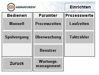
57 Page 57 von 83

58 H05 Manual screen In manual mode (on site operation), individual sequences can be executed or the cycle lock can be filled or emptied separately. In addition to this is a completely manual operation of the individual fixtures by making the selection in the image representation. The respective fixture is opened by clicking on it once. If the button is deselected, the fixture will close. Page 58 von 83

59 H06 Process times screen Explanation: Parameter Description Unit Default Ventilation duration Time for how long before the filling the 0 2,000 ms bypass fixture from the input is opened. 100,000 ms Filling duration Time of how long the input fixture is 1,000 2,000 ms opened to fill the intermediate tube piece. 100,000 ms Wait time Wait time for the material in the intermediate 0 2,000 ms tube piece before delivery. 100,000 ms Ventilation duration Time for long the bypass fixture from the output is opened before emptying ,000 ms 2,000 ms Emptying duration Total run time Time of how long the input fixture is opened to empty the intermediate tube piece. Sum of all process times listed above, including internal delay times. 1, ,000 ms ms - 2,000 ms Page 59 von 83

60 H07 Monitoring screen Explanation: Parameter Description Unit Default Delay error messaging Delay time between the "normal" operat- 0 2,000 ms states and the classification of faulty states as an error. 100,000 ms Mutual locking Dead time between two activations of different fixtures. 1, ,000 ms 2,000 ms Max. permissible run time Run time of the last cycle Upper limit for the duration of the individual cycles. This value is defined by the total process of the cycle lock and must be entered by the customer. The duration of each cycle is measured in the control and results from the sum of all set process times (filling duration, waiting intermediate setting, etc.) and all other process values (activation duration of the drives, delays, etc.). If this measures value exceeds the ""max. permissible runtime", the error "runtime exceeded" will appear. ms - ms - Page 60 von 83
61 H08 User screen Explanation: Parameter Description Unit Default Autom. user log off Once the set time has been reached, 0 600,000 ms the user will be logged off automatically. "Set up" can first be selected after logging in again.? ms New password The current password is displayed in this field and cannot be changed. text ebro Page 61 von 83
62 H09 Maintenance management screen Explanation: Parameter Description Unit Default Maximum switch cycles from the fixtures number Maximum runtime deviation Due to wear to the sleeves, the maximum switch cycles of the fixtures are limited. This value is strongly dependent on the process (medium, pressure, etc.) and should be observed by the manufacturer as a recommendation. The activation times (opening and closing times) are monitored from the switching of the signal output up to reaching the final position. Since two fixtures are available as a reference for each other, differences are evaluated in the activation times and a notification is emitted if the set "maximum runtime deviation" is exceeded. These runtimes can be found under "Process Values" "Runtimes" ,000 ms Dependent on the fixture type 1,000 ms Page 62 von 83

63 H10 Runtime screen In the "Runtime" screen, the last times from the activation of the individual fixtures can be found. This time is the value between the SPS command and the ultimate reaching of the final position. The opening and closing times for the two fixtures should be approximately similar with the same construction size and type. The "Maximum runtime deviation" parameter processes these values for a prediction of the maintenance state. Page 63 von 83

64 H11 Clock counter screen Explanation: The clock counters are remanent and cannot be influenced by the user. The overview serves for the inspection of the operating history from the cycle lock. Parameter Description Unit Default Number of lock Clock counter from completely executed number - cycles lock runs Incoming fixture Clock counter from the incoming fixture Outgoing fixture Clock counter from the outgoing fixture Bypass entrance Clock counter from the bypass fixture entrance Bypass exit Clock counter from the bypass fixture exit Page 64 von 83


65 H12 Flushing process screen An additional selection in the Setup sub-menu exists for the flushing process. When the button is pressed, the following safety note will appear on the screen: "Caution, both inlet and outlet fixtures are opened simultaneously during the flushing process!" "Do you want to continue?" If you select the "Yes" button, another window will appear with a final selection of the flushing process. Once the "flushing process" button is enabled, both fixtures will open. If the button is disabled, both fixtures will close again. Page 65 von 83
66 I) Programming SPS I01 Program organization There are two operating modes - automatic and manual. A single sequence or permanent run can be selected in the automatic mode. The program is organized as follows: Templates Main Lock cycle Inputs_outputs Manual Organization Sequence counter Runtime Fixture control Description In Main, the operating mode selection and the error and notification handling are located. Main template for automatic mode. The individual steps worked through sequentially here. Assignment of the inputs and outputs as well as locking of the signals among each other. With a possible connection to a superior control unit, these commands (binary inputs or signals through a field bus) are executed in a self-retaining manner. The command signals from the visualization are also designed in a self-retaining manner. All actions that are possible in the manual operation are organized here. This includes the execution of individual sequences (complete cycle), filling, emptying and the separate, time-independent controlling of all drives. General program parts like time, creation of the sequence signal and user log in The lock cycles and any activation of the fixtures are counted here. The activation times are dependent on different factors of influence. The runtime from the last sequence cycle is measured in order to compare the runtime monitoring with the process data after every cycle. Additionally, the activation times from the drives (signal output until the final position is reached) are measured, which are also included in the runtime monitoring. A maximum runtime deviation can be set. This cannot be mixed up with the runtime monitoring. During the runtime monitoring for the max. permissible cycle time up to the output of an error, for example, in the event of a blockade, the runtime deviation measures the difference of the activation times from the input and output fixture in order to determine wear and stiffness early enough. Function template for controlling and monitoring the drives. Page 66 von 83
67 I02 Software technical locking Independent of the operating mode and the external signal states, all fixtures are locked with each other through locking components. Plus there is a dead time that delays the opening of a fixture after it has been successfully closed. I03 Access protection The automatic mode is freely accessible. The automatic operating mode must be disabled and a password correctly entered to select "Set up". I04 Safety setting There is an emergency off command input. This signal is used internally to immediately stop all processes and shutting down of all outputs. I05 External control External overview of control functions (binary inputs or different field buses). Identification Automatic Individual sequence Permanent run Safety position (emergency off) Explanation The cycle lock can only be operated by external commands in automatic mode. If the cycle lock is not in the automatic mode, it is in the manual operating status. With an increasing flank in the automatic mode, an individual sequence is executed. After this the cycle lock is back in the basic setting. With an increasing flank in the automatic mode, a permanent run is executed. Initially, it is first emptied, then the lock process is executed in a cyclical manner until another signal flank ends the permanent run. The current cycle is executed until the end. Is handled internally like an emergency off signal. If the signal comes, the automatic mode is ended immediately, all outputs are turned off. Page 67 von 83
68 J) Setting and adjusting J01 General settings The cycle lock must be set up for the media to be processed for operation. However, maintenance and upkeep work may lead to the settings having to be reset. Before beginning the setting work, read the Safety chapter. The listed safety notes must be followed and are valid for all sub-chapters. Moreover, observe the operating instructions for the purchased parts. You should empty the complete cycle lock for setting and maintenance work and remove all media from the connected tubing system. The setting or adjusting must be approved by the operator and may only be executed by qualified staff. HAZARD Risk of death through electrical voltage. Severe injuries or death through electric shock. The connecting of the cycle lock may only be executed by an electrician. Establish a freedom of voltage and secure the cycle lock against being turned on again. HAZARD Hazard through uncontrolled starting pneumatic components. Severe injuries with incorrectly connected pneumatic components or for pneumatic components that start without being controlled. The pneumatic components may only be connected by a specialist. All components and connections must be examined before turning on the pneumatic system. CAUTION Hazard through operating or hazardous substances or through media. Sever injuries or damage to the system. The safety specifications from the operating and hazardous substances must be present and observed. Use the personal protection equipment required in the safety specifications when handling the respective hazardous substance. Page 68 von 83
69 CAUTION Damage and disruptions on the machine due to incorrect settings. Property damage to the machine and, if applicable, low lifespan. Execute setting work on the machine properly! Check settings NOTE Release system and secure against turning on again with a lock. Release electrical components and systems during all work, before maintenance, setting and upkeep and secure against turning back on. Release the pressure for all work on pneumatic components and systems and secure against pressure. Page 69 von 83
70 K) Maintenance and upkeep K01 General maintenance and upkeep Before beginning all maintenance and upkeep work, read through the Safety chapter. When purchasing spare parts and wear parts, original parts from the EBRO ARMATUREN GmbH and the purchase parts from the manufacturer must be used. It is pointed out that spare parts not delivered from the corresponding manufacturer are not inspected and approved. The installation or usage of such parts may under circumstances cause negative constructional changes to the defined properties of the cycle lock and thereby impair the active or passive operating safety. For damages that are created through the usage of non-original parts and accessories, the manufacturer has no liability. Before beginning every shift, the cycle lock must be subject to a short inspection in order to recognize possible damages early on and be able to take required measures for disruption free production processes. The work and activities on the cycle lock may only be executed by qualified staff, please also observe the Qualified Staff chapter for this. The listed safety notes must be followed and are valid for all sub-chapters. Also observe the operating manual from the connected processing machine, the tubing system and that of the programming. You should empty the complete cycle lock for setting and maintenance work and remove all media from the connected tubing system. The maintenance must be approved by the operator and may only be executed by qualified staff. CAUTION Damage and disruptions on the machine due to incorrect maintenance. Property damage to the machine and, if applicable, low lifespan. Maintain and repair the machine according to the defined interval! Observe shift operation! HAZARD Risk of death through electrical voltage. Severe injuries or death through electric shock. The connecting of the cycle lock may only be executed by an electrician. Establish a freedom of voltage and secure the cycle lock against being turned on again. Page 70 von 83
71 HAZARD Hazard through uncontrolled starting pneumatic components. Severe injuries with incorrectly connected pneumatic components or for pneumatic components that start without being controlled. The pneumatic components may only be connected by a specialist. All components and connections must be examined before turning on the pneumatic system. CAUTION Hazard through operating or hazardous substances or through media. Sever injuries or damage to the system. The safety specifications from the operating and hazardous substances must be present and observed. Use the personal protection equipment required in the safety specifications when handling the respective hazardous substance. NOTE Release system and secure against turning on again with a lock. Release electrical components and systems for all work, before maintenance, during adjustment and maintenance and secure against turning on again. Release the pressure for all work on pneumatic components and systems and secure against pressure. Page 71 von 83
72 K02 Maintenance intervals Element Maintenance activity Maintenance intervals Information Before every shift Daily Semiannually Total cycle lock Seal from the cycle lock and the flange connections Changes in the operating behavior, in particular those that impair the safety, must be reported immediately and repaired! Immediately report and repair leaks! Total cycle lock Drives Fixtures Cleaning Control Control All contaminations must be removed at least every 6 months! All drives must be subject to a visual inspection at least every 6 months! All drives must be subject to a visual inspection at least every 6 months! Page 72 von 83
73 K03 Cleaning of the cycle lock before installation All internal areas of the fixtures must be free of contamination, in particular there may not be any hard or sharp particles here. This also applies to the tube sections to be connected on the construction side. The tube sections and the flanges must be clean and not have any damages. In particular, remember that the cover in the casing from the fixture may not come into contact with lubricants, cleaning materials or other substances that do not have proven suitability or are approved by the EBRO ARMATUREN GmbH. Unsuitable cleaning agents or substances may lead to contamination, swelling or damage to the fixture. CAUTION Leaking through contamination. Contamination in fixtures, flanges and construction-side tube sections must be removed. Contamination that is not removed may lead to damage to the seal surfaces, this in turn leads to leaking. Make sure that the contamination is removed in a proper manner! K04 General cleaning of the cycle lock When operating the cycle lock, a mixture of oil, dust and other foreign objects is occasionally created. The operation and functionality of the cycle lock may be disrupted by these deposits. In order to avoid these disruptions, you must comply with the maintenance intervals and the cycle lock must be cleaned externally at least every 6 months. HAZARD Hazard through uncontrollably moving components. Severe injuries or death when working on running systems. Before all cleaning work, the cycle lock must be released of all pressure and secured against being turned on again unexpectedly. Do not execute cleaning work during running operation. CAUTION Hazard through incorrect or aggressive cleaning agent. Injuries or damages to the system. The safety specifications for the cleaning agent must be present and observed. Only use a dry cloth and, if applicable, conventional cleaners. Page 73 von 83
74 K05 Maintenance of the drives The drives are free of maintenance, because the cylinders are equipped with lifespan lubrication. Nevertheless, the drives should be subject to a visual inspection semi-annually and, if applicable, cleaned with a towel. Pay attention to the maintenance specifications from the construction side compressed air supply. The compressed air used must be filtered with a filter with a 40 μm mesh size in order to protect the magnet valve. The compressed air must be dried and should be slightly greased with switch cycles of 4 x/min. In order to avoid these disruptions, you must comply with the maintenance intervals and the drives must be cleaned externally at least every 6 months. K06 Maintenance of the fixture The fixtures themselves are maintenance free. Nevertheless, the fixtures should be subject to a visual inspection semi-annually and, if applicable, cleaned with a towel. During the visual inspection, please also pay attention to the flange connections and screws for the construction side tubing system. If applicable, leaks may be created here, which must be immediately reported and repaired. In order to avoid these disruptions, you must comply with the maintenance intervals and the fixture must be cleaned externally at least every 6 months. Furthermore, the flange connections should be inspected manually at least once a year and tightened with a torque wrench. Observe the specified torque of the screws. Page 74 von 83
75 L) Disruptions, causes and repair L01 General disruptions Before beginning the troubleshooting, read the chapter Safety Notes. The listed safety notes must be followed and are valid for all sub-chapters. Also observe the information from the connected processing machine, the tubing system and that of the programming. HAZARD Risk of death through electrical voltage. Severe injuries or death through electric shock. The connecting of the cycle lock may only be executed by an electrician. Establish a freedom of voltage and secure the cycle lock against being turned on again. HAZARD Hazard through uncontrolled starting pneumatic components. Severe injuries with incorrectly connected pneumatic components or for pneumatic components that start without being controlled. The pneumatic components may only be connected by a specialist. All components and connections must be examined before turning on the pneumatic system. CAUTION Hazard through operating or hazardous substances or through media. Sever injuries or damage to the system. The safety specifications from the operating and hazardous substances must be present and observed. Use the personal protection equipment required in the safety specifications when handling the respective hazardous substance. NOTE Release system and secure against turning on again with a lock. Release electrical components and systems for all work, before maintenance, during adjustment and maintenance and secure against turning on again. Release the pressure for all work on pneumatic components and systems and secure against pressure. Page 75 von 83

76 L02 Error display screen Errors are signalized through a blinking of the current status in red. By selecting the "notifications" field, you can end up in the overview of the error notifications. All error notifications result in the current program being stopped and a moving to the safety positions. Once the cause of the error has been repaired, the cycle lock can be reset through the "ACK" button. L03 Errors Cause Repair Error Cause Repair Leak on the flange connection to the tubing In the area of the flange connections due to an incorrectly mounted connecting screw or due to damages to the seal areas, media escapes between the fixtures of the cycle lock and the tubing system. Seal flange connection between casing and tubing. Observe the instructions in the operating manual for the tubing and installation note for the corresponding fixture. If the leak cannot be repaired by tightening the flange, it must be guaranteed that the tubing flanges are aligned and parallel to each other. And/or replace the cover from the casing. Leak on the shaft seal Leaking of the shaft seal. If the shaft seal is leaking, a repair is necessary. The shaft seal must be replaced. Page 76 von 83
Original Assembly Instruction with operating manual and technical annex
 INFLAS PRO INFLAS PRO Sample illustrations, all possible model variations are not displayed!! Original Assembly Instruction with operating manual and technical annex pursuant to EC Machinery Directive
Operating and maintenance manual Filter and reducing station Series / 1.0
 Operating and maintenance manual Filter and reducing station Series 961 04.2017 / 1.0 Original instructions ARCA Regler GmbH. All rights reserved. Cover picture background: Freepik.com ARCA Regler GmbH
Pressure maintenance valve SDV-P / SDV-P-E
 Translation of the original manual Pressure maintenance valve SDV-P / SDV-P-E Assembly and Operating Manual Superior Clamping and Gripping Imprint Imprint Copyright: This manual remains the copyrighted
Type BBS-03, BBS-05, BBS-06, BBS-25
 Type BBS-03, BBS-05, BBS-06, BBS-25 Sterile connection elements Sterile Verbindungselemente Raccords union stériles Operating Instructions Bedienungsanleitung Manuel d utilisation 1. THE OPERATING INSTRUCTIONS
1 DRIVE INDUSTRIAL IMPACT WRENCH
 1 DRIVE INDUSTRIAL IMPACT WRENCH 92622 ASSEMBLY AND OPERATING INSTRUCTIONS 3491 Mission Oaks Blvd., Camarillo, CA 93011 Visit our Web site at http://www.harborfreight.com Copyright 2004 by Harbor Freight
Instruction manual. for. high purity gas pigtails 200 bar / 300 bar
 Instruction manual for high purity gas pigtails 200 bar / 300 bar Contents Contents... 2 1. Preface... 3 1.1 Overview... 3 1.2 General... 3 1.3 Intended use... 4 1.4 Personnel requirements... 4 2. For
Flowmeter. Original operating manual DFM
 Flowmeter Original operating manual Series DFM 165 350 Version BA-2016.08.09 EN Print-No. 300 458 TR MA DE Rev002 ASV Stübbe GmbH & Co. KG Hollwieser Straße 5 32602 Vlotho Germany Phone: +49 (0) 5733-799-0
Safety Powder Spray Systems
 Instruction Sheet P/N 107 952C Safety Powder Spray Systems 1. Introduction This section contains general safety instructions for using your Nordson equipment. Task- and equipment-specific warnings are
Wafer Check Valve. Contents. User s Manual. (1) Be sure to read the following description of our product warranty 1
 Be sure to read the following description of our product warranty 1") Serial No. H-V066-E-3 Wafer Check Valve User s Manual Contents (1) Be sure to read the following description of our product warranty 1 (2) General operating instructions 2 (3) General instructions for
Serial No. H-V066-E-3 Wafer Check Valve User s Manual Contents (1) Be sure to read the following description of our product warranty 1 (2) General operating instructions 2 (3) General instructions for
Operating Instructions
 Operating Instructions Light-metal Ex d enclosures / flameproof enclosure > 8265/0 Empty enclosure > 8265/4 Control panel, integrated in Ex e enclosure > 8265/5 Control panel Table of Contents 1 Table
OWNER S MANUAL. Page: 1 of 8
 Air Needle Scaler OWNER S MANUAL WARNING: Read carefully and understand all INSTRUCTIONS before operating. Failure to follow the safety rules and other basic safety precautions may result in serious personal
Storage Shelving. User Manual [Revision 3.0 May 2017]
![Storage Shelving. User Manual [Revision 3.0 May 2017]](/thumbs/90/103875414.jpg "Storage Shelving. User Manual [Revision 3.0 May 2017]") User Manual [Revision 3.0 May 2017] READ THIS MANUAL CAREFULLY BEFORE USE FAILURE TO DO SO MAY RESULT IN INJURY, PROPERTY DAMAGE AND MAY VOID WARRANTY. KEEP THIS MANUAL FOR FUTURE REFERENCE. Products covered
User Manual [Revision 3.0 May 2017] READ THIS MANUAL CAREFULLY BEFORE USE FAILURE TO DO SO MAY RESULT IN INJURY, PROPERTY DAMAGE AND MAY VOID WARRANTY. KEEP THIS MANUAL FOR FUTURE REFERENCE. Products covered
Ball valve. Operating instructions for series. Version BA Print-No TR MA DE Rev001
 Ball valve Operating instructions for series Version BA-2016.02.05 Print-No. 300 587 TR MA DE Rev001 We reserve the right to make technical changes. Read carefully before use. Save for future use. ASV
Modular valve block. Operating manual Series MVB 100/200. Version BA EN Print-No TR MA DE Rev001
 Modular valve block Operating manual Series MVB 100/200 Version BA-2016.04.20 EN Print-No. 300 627 TR MA DE Rev001 ASV Stübbe GmbH & Co. KG Hollwieser Straße 5 32602 Vlotho Germany Phone: +49 (0) 5733-799-0
Type Operating Instructions. 2/2-way solenoid valve 2/2-Wege Magnetventil Electrovanne 2/2 voies.
 2/2-way solenoid valve 2/2-Wege Magnetventil Electrovanne 2/2 voies We reserve the right to make technical changes without notice. Technische Änderungen vorbehalten. Sous réserve de modifications techniques.
KTM OM-2 SPLIT BODY FLOATING BALL VALVES INSTALLATION AND MAINTENANCE INSTRUCTIONS
 Before installation these instructions must be fully read and understood SECTION 1 - STORAGE 1.1 Preparation and preservation for storage All valves should be properly packed in order to protect the parts
Type 2000 INOX. Quickstart. English Deutsch Français. 2/2-way angle seat valve 2/2-Wege Schrägsitzventil Vanne à siège incliné 2/2 voies
 Type 2000 INOX 2/2-way angle seat valve 2/2-Wege Schrägsitzventil Vanne à siège incliné 2/2 voies Quickstart English Deutsch Français Contents 1 QUICKSTART... 2 2 CONTACT ADDRESS... 2 3 INTENDED USE...
Innovative Vacuum for Automation. Operating Instructions Dust Filter STF P / STF-D P.
 Innovative Vacuum for Automation EN Operating Instructions Dust Filter STF P / STF-D P 30.30.01.00059/02 11.2014 www.schmalz.com Note These operating instructions were written in the German language. This
INSTALLATION COMMISSIONING, OPERATION & MAINTENANCE MANUAL
 WedgeRock RW Series Worm Gear Actuators INSTALLATION COMMISSIONING, OPERATION & MAINTENANCE MANUAL Revision 01 Date 4/3/17 Page 1 Table of Contents 1.0 INTRODUCTION... 4 1.1 PURPOSE... 4 1.2 AUDIENCE...
Installation, Operating & Maintenance Instructions. All-metal gate valve with extended pneumatic actuator. Series 48 DN mm (I.D.
 Installation, Operating & Maintenance Instructions All-metal gate valve with extended pneumatic actuator Series 48 DN 16 320 mm (I.D. ⅝" 12") This manual is valid for the following product ordering numbers:
Type 0404 / /2-way solenoid valve 2/2-Wege-Magnetventil Électrovanne 2/2 voies Operating Instructions Bedienungsanleitung Manuel d utilisation
 Type 0404 / 5404 2/2-way solenoid valve 2/2-Wege-Magnetventil Électrovanne 2/2 voies Operating Instructions Bedienungsanleitung Manuel d utilisation 1 OPERATING INSTRUCTIONS The operating instructions
Installation and Operating Instructions Bypass Flow Meter DST
 Installation and Operating Instructions Bypass Flow Meter DST DST_gb_A4_1.0.doc Version 1.0 1 von 10 Contents 1. Foreword... 3 2. Safety... 3 2.1. Symbol and meaning... 3 2.2. General safety directions
Installation, Operating & Maintenance Instructions. Variable leak valve with manual actuator. Series 590 DN 16 mm (I. D. ⅝") E
 E") Installation, Operating & Maintenance Instructions Variable leak valve with manual actuator DN 16 mm (I. D. ⅝") This manual is valid for the following product ordering numbers: 59024-. E01 -... Sample
Installation, Operating & Maintenance Instructions Variable leak valve with manual actuator DN 16 mm (I. D. ⅝") This manual is valid for the following product ordering numbers: 59024-. E01 -... Sample
Instructions for Installation, Use and Maintenance FSI Safety Tank Shower Systems
 Instructions for Installation, Use and Maintenance FSI Safety Tank Shower Systems per DIN 12 899 T1-3 and ANSI Z 358-2004 Table of Contents for Instructions for Use Section 1 Manufacturer, Safety Shower
VS18/26 with PROFINET and EtherNet/IP Interface. ATEX Installation Instructions
 VS18/26 with PROFINET and EtherNet/IP Interface ATEX Installation Instructions INDEX 1. INTENDED USAGE 3 2. OPERATING MANUAL ATEX 4 2.1 General conditions 4 2.2 Installation 5 2.3 Operating 5 2.4 Failures
Measurement accessories METPOINT OCV for the measurement in systems up to 40 bar
 EN - english Instructions for installation and operation Measurement accessories METPOINT OCV for the measurement in systems up to 40 bar Dear customer, Thank you for deciding in favour of the METPOINT
Safety. Operating instructions Solenoid valve for gas VG 6 VG 15/10 DANGER. Contents WARNING CAUTION. Changes to edition 09.14
 15 Elster GmbH Edition 7.15 Translation from the German 519 D F NL I E DK S N P GR TR CZ PL RUS H www.docuthek.com Operating instructions Solenoid valve for gas VG VG 15/1 Contents Solenoid valve for gas
Manual Actuated Boiler Blowdown Valves
 Manual Actuated Boiler Blowdown Valves Installation and Maintenance Instructions 1. Safety information 2. General product information 3. Installation 4. Operation 5. Maintenance 6. Spare parts p.1 1. Safety
Operating Instructions Temperature Measuring System MF420-5T-100
 Operating Instructions Temperature Measuring System Dnhqdhnjah MF420-5T-100 Dmsklakla Read before use! Observe all safety instructions! Keep for future reference! Fon +49/7221/64103 Fax +49/7221/17103
Mounting and Operating Instructions EB 2558 EN. Self-operated Pressure Regulators. Type Pressure Build-up Regulator
 Self-operated Pressure Regulators Type 2357-31 Pressure Build-up Regulator with safety function and integrated excess pressure valve Type 2357-31 with non-return unit at port C Ports A and B with soldering
Operating Instruction English. Revision A Date author NH This operating instruction is not subject to updating. Airgun
 Revision A Date 23.11.2012 author NH This operating instruction is not subject to updating Airgun 95400 1 This airgun is a quality product with special focus on high functionality, easy handling, safety
Pressure relief valve
 Pressure relief valve Operating manual Series DHV 712 R Version BA-2016.01.19 EN Print-No. 300 472 TR MA DE Rev001 ASV Stübbe GmbH & Co. KG Hollwieser Straße 5 32602 Vlotho Germany Phone: +49 (0) 5733-799-0
Pressure relief valve
 Pressure relief valve Operating manual Series DHV 718 Version BA-2016.01.11 EN Print-No. 300 524 TR MA DE Rev001 ASV Stübbe GmbH & Co. KG Hollwieser Straße 5 32602 Vlotho Germany Phone: +49 (0) 5733-799-0
LUBRICATOR ASSEMBLY AND OPERATING INSTRUCTIONS
 AIR FILTER, REGULATOR AND LUBRICATOR 4035 ASSEMBLY AND OPERATING INSTRUCTIONS 349 Mission Oaks Blvd., Camarillo, CA 930 Visit our Web site at http://www.harborfreight.com Copyright 004 by Harbor Freight
Operating Instructions
 Operating Instructions Ex d Enclosures in Light Metal / Flameproof Encapsulation > 8265/0 Empty Enclosure > 8265/4 controller, installed in Ex e enclosure > 8265/5 controller Contents 1 Contents 1 Contents...2
6-5 Maintenance Manual
 Non Return Valve 6-5 Maintenance Manual Contents 1. PRODUCT DESCRIPTION... 1 1.1 How it works... 1 1.2 Overall dimensions... 3 1.3 Technical datasheet... 4 1.3.1 Push flow situation... 4 1.3.2 Pull flow
Needle valve. Contents. User s Manual. (1) Be sure to read the following warranty clauses of our product 1. (2) General operating instructions 2
 Be sure to read the following warranty clauses of our product 1. (2) General operating instructions 2") Serial No. H-V024-E-7 Needle valve User s Manual Contents (1) Be sure to read the following warranty clauses of our product 1 (2) General operating instructions 2 (3) General instructions for transportation,
Serial No. H-V024-E-7 Needle valve User s Manual Contents (1) Be sure to read the following warranty clauses of our product 1 (2) General operating instructions 2 (3) General instructions for transportation,
OPERATING INSTRUCTIONS (Translation) Rope Winch Type , , ,75
 Rope Winch Type , , ,75") OPERATING INSTRUCTIONS (Translation) Rope Winch Type 4202.0,5 4585.0,5 4585.0,75 GB The length of the rope is correct if: 1. User groups Duties Operator Operation, visual inspection Specialist Assembly,
OPERATING INSTRUCTIONS (Translation) Rope Winch Type 4202.0,5 4585.0,5 4585.0,75 GB The length of the rope is correct if: 1. User groups Duties Operator Operation, visual inspection Specialist Assembly,
Declaration of Conformity as per Directive 97/23/EC
 Declaration of Conformity as per Directive 97/23/EC The manufacturer declares that:, 47906 Kempen, Germany Continuous, inline sampling valves Series 27f, with packing Operate with either; Star lever, or
Norrsken Family Booklet
 Section 1: Introduction Low Energy Designs produce efficient and effective LED based lighting products for commercial, retail and industry purposes. Each product may contain specific details on its operation
Operating Instructions in accordance with the Machines Directive 2006/42/EC
 Lubricating Equipment Metering Technology for Grease and Oil High Pressure Hydraulic Customised Developments Operating Instructions in accordance with the Machines Directive 2006/42/EC Compressed air filling
Composite Pistol-Type Air Needle Scaler OWNER S MANUAL
 Composite Pistol-Type Air Needle Scaler OWNER S MANUAL WARNING: Read carefully and understand all INSTRUCTIONS before operating. Failure to follow the safety rules and other basic safety precautions may
Control Valve with ZK Radial Stage Nozzle ZK 210. Original Installation Instructions English
 Control Valve with ZK Radial Stage Nozzle ZK 210 EN English Original Installation Instructions 810691-00 Contents Important Notes Page Usage for the Intended Purpose... 3 Safety Note... 3 Warning... 4
Non-Return Valve SRK 22A
 Non-Return Valve SRK 22A Original Installation Instructions 819238-02 Contents Foreword... 3 Availability... 3 Formatting features in the document... 3 Safety... 3 Use for the intended purpose... 3 Basic
Operating Instructions. Ball valve fitting according to ZB For pressure transmitter VEGABAR 82. Document ID: 50027
 Operating Instructions Ball valve fitting according to ZB 2553 For pressure transmitter VEGABAR 82 Document ID: 50027 Contents Contents 1 About this document 1.1 Function... 3 1.2 Target group... 3 1.3
Neotecha SAPRO - Aseptic sampling valve SV Installation, operation and maintenance instructions
 Before installation these instructions must be fully read and understood 2 Safety Please read these instructions carefully. 2.1 General danger potential Not paying attention to this instruction Incautious
OPERATING MANUAL. Contents. Bottom outlet ball valve Type ecoline
 OPERATING MANUAL Bottom outlet ball valve Type ecoline Contents 1 General Information 2 Safety 3 Packing, Handling, Storing 4 Product description 5 Preparation, Assembly 6 Commissioning 7 Handling 8 Attendance
Type 3709 Pneumatic Lock-up Valve. Translation of original instructions. Mounting and Operating Instructions EB 8391 EN
 Type 3709 Pneumatic Lock-up Valve Translation of original instructions Mounting and Operating Instructions EB 8391 EN Edition July 2017 Note on these mounting and operating instructions These mounting
Declaration of Conformity as per Directive 97/23/EC
 Declaration of Conformity as per Directive 97/23/EC The manufacturer declares that:, 47906 Kempen, Germany Multi-way diverting valves Series 29a and Series 29b, with packing with lever 1. The valves are
Instruction Manual Contact Pressure Vacuum Gauge
 MS10 Instruction Manual Contact Pressure Vacuum Gauge Table of Contents 1. Safety Instructions 2. Intended Applications 3. Product Description and Functions 4. Installation 5. Commissioning 6. Maintenance
PRAHER PLC-MP AQUASTAR MANAUL 2009
 PRAHER PLC-MP AQUASTAR MANAUL 2009 1. Copyrights This Operating Manual contains copyright-protected information. All rights reserved to Praher Kunststofftechnik GmbH. This Operating Manual is designed
Operating Instructions in compliance with Pressure Equipment Directive 2014/68/EU. FAS Brass Check Valve RDL
 Operating Instructions in compliance with Pressure Equipment Directive 2014/68/EU FAS Brass Check Valve RDL Please read these operating instructions carefully to ensure a safe operation and keep the same
Declaration of Conformity as per Directive 97/23/EC
 Declaration of Conformity as per Directive 97/23/EC The manufacturer declares that:, 47906 Kempen, Germany Discontinous, inline sampling valves Series 27a and Series 27g, with packing with lever (180 )
Safety instructions and operating manual
 5-Master Safety instructions and operating manual TBF-PyroTec GmbH Lichterfelder Str. 5 A 21502 Geesthacht Tel.: + 49 (0)4152 157 9950 Fax: + 49 (0)4152 157 9951 Flame projector 5-Master Safety instructions
Actuating elements for ComEx
 Description A large number of variants and versions of actuating elements are available for the ComEx control and indicator units. All actuating elements are made of high-quality thermoplastic and conform
MANUAL DIRECT PURGE OPTION. UNION Instruments GmbH CWD2005 PLUS. General information, safety standards and regulations for direct purge option
 MANUAL DIRECT PURGE OPTION UNION Instruments GmbH CWD2005 PLUS General information, safety standards and regulations for direct purge option Version: V1.00 Stand: 24.03.2010 Union Instruments GmbH Zeppelinstr.
PH01 Perfusion Cannula Manual
 PH01 Perfusion Cannula Manual Information in this document is subject to change without notice. No part of this document may be reproduced or transmitted without the express written permission of Multi
Installation and Maintenance Instruction Manual
 Installation and Maintenance Instruction Manual Bi-metal Thermometer Model A and E in a configuration - pursuant to ASME B40.200: ##=E#=### or ##=ERT#=### - pursuant to EN 13190: ###=A#=### or ##=ART#=###
Magnetic level switch type MR783 Instruction Manual
 Magnetic level switch Magnetic level switch type MR783 1. DESCRIPTION page 3 1.1 Operation page 3 1.2 Application page 3 1.3 Description page 3 2. SPECIFICATIONS page 3 2.1 Service Conditions page 4 2.2
ELECTRICAL (COMPREHENSIVE) SAFETY PROGRAM REGULATORY STANDARD: OSHA - 29 CFR CFR , ,
 SAFETY PROGRAM REGULATORY STANDARD: OSHA - 29 CFR CFR , ,") ELECTRICAL (COMPREHENSIVE) SAFETY PROGRAM REGULATORY STANDARD: OSHA - 29 CFR 1910.331 335-29 CFR 1926.302, 1926.416, 1926.417 BASIS: The National Safety Council estimates that there are at least 300 deaths
ELECTRICAL (COMPREHENSIVE) SAFETY PROGRAM REGULATORY STANDARD: OSHA - 29 CFR 1910.331 335-29 CFR 1926.302, 1926.416, 1926.417 BASIS: The National Safety Council estimates that there are at least 300 deaths
INSTALLATION, OPERATION AND SERVICE MANUAL ABS AIR BAG LIFT
 INSTALLATION, OPERATION AND SERVICE MANUAL ABS AIR BAG LIFT P.O. Box 1058 1058 West Industrial Avenue Guthrie, OK 73044-1058 405-282-5200 FAX: 405-282-8105 www.autoquip.com Item # 830ABS Version 1.0 07/2001
Translation of the original Operating Instructions for HKS rubber compensators
 Because of their flexible elements and mechanisms, HKS rubber compensators are susceptible to damage of all types and adverse loads in operation. For reliable operation of a compensator and, thus, the
AIR INLINE METAL SHEAR
 AIR INLINE METAL SHEAR ASSEMBLY and OPERATING INSTRUCTIONS 3491 Mission Oaks Blvd. / Camarillo, CA 93011 Copyright 1997 by Harbor Freight Tools. All rights reserved. No portion of this manual or any artwork
Product Manual B-Safety ClassicLine & PremiumLine Emergency Eyewash and Eye/Face Wash Equipment
 Product Manual B-Safety ClassicLine & PremiumLine Emergency Eyewash and Eye/Face Wash Equipment 1. Application Emergency eyewash and eye/face wash equipment are prescribed first aid installations for workplaces
Diaphragm Pressure Keeping Valve
 Product: Diaphragm pressure keeping valve Type: 620.D 622.D 623.D 624.D 625.D 626.D 627.D Please state here the exact type and serial number of your diaphragm pressure keeping valve. (can be read off the
TEM# Air Hammer Combo USER'S MANUAL
 Air Tools TEM# 40 Air Hammer Combo USER'S MANUAL Read carefully and understand RULES FOR SAFE OPERATION and instructions before operating. Failure to follow the safety rules and other basic safety precautions
Fiat - Argentina - Wheel Aligner / Headlamp Aimer #16435
 2017 Wheel Aligner / Headlamp Aimer Operation & Maintenance Manual Safety Fori Automation Version 1.2 4/21/2017 SECTION 1.0 SAFETY These Safety Requirements Must Be Read And Understood By All Machine Operators,
Bray/ VAAS O-Ported Series Knife Gate Valve 770/780 Series Operation and Maintenance Manual
 Bray/ VAAS Knife Gate Valve 770/780 Series Operations and Maintenance Manual Table of Contents Definition of Terms 1 Safety Instructions 1 Introduction 2 Unpacking 2 Storage 2 Installation 2 Commissioning
Installation & Operation Manual Proven Quality since 1892
 Content 1. ERIKS operating companies 2. Product description 3. Requirements for maintenance staff 4. Transport and storage 5. Function 6. Application 7. Installation 8. Maintenance 9. Service and repair
PROPORTIONING VALVE. Model 150 INSTRUCTION MANUAL. March 2017 IMS Company Stafford Road
 PROPORTIONING VALVE Model 150 INSTRUCTION MANUAL March 2017 IMS Company 10373 Stafford Road Telephone: (440) 543-1615 Fax: (440) 543-1069 Email: sales@imscompany.com 1 Introduction IMS Company reserves
KBV21i and KBV40i Key Operated Boiler Blowdown Valves Installation and Maintenance Instructions
 4059051/3 IM-P405-48 EMM Issue 3 KBV21i and KBV40i Key Operated Boiler Blowdown Valves Installation and Maintenance Instructions 1. Safety information 2. General product information 3. Installation 4.
3M Liqui-Cel EXF-10x28 Series Membrane Contactor
 Membrane Contactors 3M Liqui-Cel EXF-10x28 Series Membrane Contactor Assembly and Disassembly Instructions 3M.com/Liqui-Cel TABLE OF CONTENTS I. Safety and Warning 3 II. Assembly Parts 4 III. Part Orientation
Pre-filter for Brushless Blower Instruction Manual
 Pre-filter for Brushless Blower 781-70-702 Instruction Manual Minebea Co., Ltd. Industrial Machinery Business Unit 251-8531 1-1-1 Katase,Fujisawa,kanagawa Contact Us Industrial Machinery Product Sales
INTENDED USE TECHNICAL SPECIFICATIONS
 1/2IN. HEAVY-DUTY AIR IMPACT WRENCH OWNER S MANUAL WARNING: Read carefully and understand all INSTRUCTIONS before operating. Failure to follow the safety rules and other basic safety precautions may result
Operating Instructions SKYJET Compact Sub-distributor
 Operating Instructions SKYJET Compact Sub-distributor INDEX Page 1. General... 2 2. Safety... 2 4 A. Distributor Type... 5 B. Number of Outlets... 5 C. Revision... 6 D. Accessories... 6 3. Application...
Safety Please read and keep in a safe place Operating instructions Linear flow control VFC Linear flow control with actuator IFC
 05 Elster GmbH Edition 0.5 Translation from the German 058 D F NL I E DK S N P GR TR CZ PL RUS H www.docuthek.com Operating instructions Linear flow control VFC Linear flow control with actuator IFC Contents
MoveRoll Conveyor Operating and Maintenance Manual
 MoveRoll Conveyor Operating and Maintenance Manual 1. Read this first! This manual contains information for protection of personnel in the roll handling area from possible injury and/or equipment damage.
Inverted Bucket Steam Trap IB 16A-7
 Inverted Bucket Steam Trap IB 16A-7 Original Installation Instructions 819114-02 Contents Preface... 3 Availability... 3 Text layout... 3 Safety... 3 Usage for the intended purpose... 3 Basic safety notes...
97C COMPRESSOR KIT 12V PART NO C COMPRESSOR KIT 24V PART NO C COMPRESSOR KIT PART NO
 97C COMPRESSOR KIT 12V PART NO. 00097 97C COMPRESSOR KIT 24V PART NO. 02497 98C COMPRESSOR KIT PART NO. 00098 97C 98C IMPORTANT: It is essential that you and any other operator of this product read and
Operating instructions Way valve DR4
 Operating instructions Way valve DR4 INDEX Page 1. General... 2 2. Safety... 2 4 A. Valve type... 4 B. Function... 4 C. Inspection... 5 D. Monitoring... 5 7 E. Accessories... 7 9 3. Application... 9 4.
Lab Cock. Contents. User s Manual (1) Be sure to read the following warranty clauses of our product 1. (2) General operating instructions 2
 Be sure to read the following warranty clauses of our product 1. (2) General operating instructions 2") Serial No. H-V005-E-6 Lab Cock Contents User s Manual (1) Be sure to read the following warranty clauses of our product 1 (2) General operating instructions 2 (3) General instructions for transportation,
Serial No. H-V005-E-6 Lab Cock Contents User s Manual (1) Be sure to read the following warranty clauses of our product 1 (2) General operating instructions 2 (3) General instructions for transportation,
Siphon vessel / Priming aid
 Manufacturer: sera GmbH sera-straße 1 34376 Immenhausen Germany Tel.: +49 5673 999-00 Fax: +49 5673 999-01 info@sera-web.com Keep the operating manual for future use! Record the exact type and serial number
Instruction Manual. Model TC1-S TopSide Clamp. top side clamp. For your personal safety READ and UNDERSTAND instructions before using tools.
 Instruction Manual Model TC1-S TopSide Clamp top side clamp (406)755-4258 (406)257-2711 www.timberlinetool.com 90 Conestoga Ct. Kalispell, MT 59901 USA For your personal safety READ and UNDERSTAND instructions
Operating Instructions in compliance with Pressure Equipment Directive 2014/68/EU. FAS Manual Brass Shut-Off Valve DN10 through DN22
 Operating Instructions in compliance with Pressure Equipment Directive 2014/68/EU FAS Manual Brass Shut-Off Valve DN10 through DN22 Please read these operating instructions carefully to ensure a safe operation
1/2 Twin Hammer Composite. Air Impact Wrench ASSEMBLY AND OPERATING INSTRUCTIONS
 1/2 Twin Hammer Composite Air Impact Wrench 95098 ASSEMBLY AND OPERATING INSTRUCTIONS Due to continuing improvements, actual product may differ slightly from the product described herein. 3491 Mission
2000 lb manual winch
 2000 lb manual winch Model 41694 Operation Instructions Due to continuing improvements, actual product may differ slightly from the product described herein. 3491 Mission Oaks Blvd., Camarillo, CA 93011
MUELLER. A Wall Type. Indicator Post. Reliable Connections. General Information 2. Technical Data/ Dimensions 3. Installation 4-5.
 Installation Instructions manual MUELLER table of contents PAGE A-20814 Wall Type General Information 2 Technical Data/ Dimensions Installation 4-5 Maintenance 6 Parts 7 Indicator Post! WARNING: 1. Read
USER S MANUAL Installation & Maintenance. VAX Series. High Pressure 2-way/3-way Coaxial Valve assuredautomation.
 VAX Series High Pressure -way/3-way Coaxial Valve USER S MANUAL Installation & Maintenance Assured Automation 19 Walnut Avenue, Clark, New Jersey 07066 Tel: 73-381-55 Fax: 73-381-383 1. GENERAL In order
AIR/OVER HYDRAULIC JACK 20 TON
 AIR/OVER HYDRAULIC JACK 0 TON 4487 ASSEMBLY AND OPERATING INSTRUCTIONS 349 Mission Oaks Blvd., Camarillo, CA 930 Visit our Web site at http://www.harborfreight.com Copyright 999 by Harbor Freight Tools.
INSTALLATION, OPERATION AND MAINTENANCE GUIDE
 INSTALLATION, OPERATION AND Placement in Pipeline System When installing Process Development & Control s ElastoTITE Elastomer-Hinged Check Valves in a pipeline, a minimum of five pipe diameters should
Declaration of Conformity as per Directive 97/23/EC and Manufacturer s Declaration as per Directive 98/37/EC
 Declaration of Conformity as per Directive 97/23/EC and Manufacturer s Declaration as per Directive 98/37/EC The manufacturer declares that:, 47906 Kempen, Germany Continuous, PFA-lined, inline sampling
Overspeed governors (113 OG Моment 250 MR, 114 OG Moment 250 A3, 115 OG Moment 250 MRL, 119 OG Moment 250 MRL/1)
") Overspeed governors (113 OG Моment 250 MR, 114 OG Moment 250 A3, 115 OG Moment 250 MRL, 119 OG Moment 250 MRL/1) Instructions for installation and operation 113 OG Моment 250 MR 115 OG Moment 250 MRL Overspeed
Overspeed governors (113 OG Моment 250 MR, 114 OG Moment 250 A3, 115 OG Moment 250 MRL, 119 OG Moment 250 MRL/1) Instructions for installation and operation 113 OG Моment 250 MR 115 OG Moment 250 MRL Overspeed
e.do Gripper Safety requirements, technical features and assembly and integration instructions
 e.do Gripper Safety requirements, technical features and assembly and integration instructions Requirements, technical features and instructions for safe installation and use of the e.do Gripper. CR00758190-en_00/2018.05
Installation, operation & maintenance manual - original version
 Installation, operation & maintenance manual - original version AVK gate valves for water and wastewater Series 01, 02, 06, 12, 15, 18, 20, 26, 32, 33, 36, 38, 50, 55 and 636 COPYRIGHT AVK GROUP A/S 2018
Type /2-Way Globe Valve 3/2-Wege-Geradsitzventil Vanne à siège droit 3/2 voies Operating Instructions Bedienungsanleitung Manuel d utilisation
 3/2-Way Globe Valve 3/2-Wege-Geradsitzventil Vanne à siège droit 3/2 voies Operating Instructions Bedienungsanleitung Manuel d utilisation We reserve the right to make technical changes without notice.
A17W49_MASEM_F_EN MANUAL
 AW9_MASEM_F_EN MANUAL CONTENTS Identification. Manufacturer. Product name. Year of manufacture. Area of use. Declaration of conformity Technical specification. Design. Function. Technical data. Electrical
Contents. Operating instructions. Pressure switch, heavy-duty version Model PSM-520
 Operating instructions Contents EN Pressure switch, heavy-duty version Model PSM-520 1. General information 2. Design and function 3. Safety 4. Transport, packaging and storage 5. Commissioning, operation
Assembly Drawing: W-311B-A01, or as applicable Parts List: W-311B-A01-1, or as applicable Special Tools: , , &
 REDQ Regulators Model 411B Barstock Design Powreactor Dome Regulator OPERATION AND MAINTENANCE Contents Scope..............................1 Installation..........................1 General Description....................1
Yoke Block Instruction Manual
 Yoke Block Instruction Manual ! WARNING IMPORTANT: READ MANUAL COMPLETELY BEFORE OPERATING THIS DEVICE This manual contains instructions on periodically required checks to be performed by the user. These
INSTRUCTIONS AND MAINTENANCE MANUAL SERIES: RT
 INSTRUCTIONS AND MAINTENANCE MANUAL 05/11/2015 SERIES: RT cmo @cmo.es http://www.cmo.es page 1 ASSEMBLY THE RT VALVE COMPLIES WITH THE FOLLOWING: Machinery Directive: DIR 2006/42/EC (MACHINERY) Pressure