CHAPTER OVERVIEW. Operating Instructions... Technical Data Sheet... Spare Parts Lists... Options (if equipped)... Attachment...
|
|
|
- Lynn Cunningham
- 5 years ago
- Views:
Transcription
1 CHAPTER OVERVIEW Operating Instructions... Technical Data Sheet... Spare Parts Lists... Options (if equipped)... Attachment... A B C D E Manufacturer in terms of 97/23/EC The full name and address of the manufacturer is: Lenhardt & Wagner GmbH An der Tuchbleiche Hüttenfeld / Germany Phone: +49 (0) Fax: +49 (0) service@lw-compressors.com Internet: Version:
2 SERVICE INFORMATION / WARRANTY Compressor information Type designation Serial number Date of construction Purchase information Purchase date First commissioned on Warranty period Dealer's stamp Warranty L&W will uphold warranty claims made during a period of 12 months from the invoice date. If the compressor was purchased from an official L&W dealer, the date on the dealer's invoice is valid. Warranty claims can only be made on presentation of the original invoice. Should verifiably defective parts have been delivered, we will decide to either replace the parts or repair them. The resulting transport and assembly costs will be invoiced. No reduction of the purchase price or changes to the contract can be made. The parts for which a claim is being made should be kept safe by the purchaser and, when requested, sent to us at their cost. Replaced parts become the property of L&W. If maintenance work is carried out without our knowledge or permission by the purchaser or a third party, we are absolved from any liability for warranty claims. As a matter of principle, warranty claims can only be made by the initial purchaser. Version:

3 A Operating Instructions Breathing Air Compressor LW 320 B MC LW 400 B MC Version:
4 T A B L E O F C O N T E N T S General Information and Technical Data General Information / Description of Warning Symbols... 4 Scope of Delivery... 5 Technical Data... 6 Unit Assembly... 7 Start Device... 8 Flow Chart... 9 A Safety Precautions Intended Use / Operators Safety Instructions on the Unit General Safety Precautions Unit Customised Safety Notices Maintenance Instructions Transportation Instructions / Safety Regulations Installation Outdoor Installation Dimensions Minimum Distances Ventilation Electrical Installation Operation Important Operation Instructions First Commissioning Daily Commissioning Filling Procedure Switch off the Compressor Remedying Faults Maintenance and Service Service, Repair and Maintenance Maintenance Lists / Maintenance Intervals Service Kits Check V-Belt Tension / Tension V-Belt Compressor Lubrication / Check Oil Level Check Oil Level Oil Change Oil Sieve Change Oil Filter Maintenance Version: A - 2
5 T A B L E O F C O N T E N T S Maintenance and Service Manuele Condensation Dump System Oil / Water Separators 2nd Stage - Maintenance Filter Housing / Filter Cartridge Filter Cartridge Change LW 320 / 400 B MC Filter Housing - Maintenance Inlet Filters / Inlet Filter Cartridge Change Cylinder Heads and Valves Fan Protection Cover Dismantling / Mounting the Fan Protection Cover Replace Inlet and Outlet Valve 1st Stage Replace Inlet and Outlet Valve 2nd Stage Replace Inlet and Outlet Valve 3rd Stage Safety Valves Pressure Maintaining / Non Return Valve Adjust Pressure Maintaining Valve O-Rings Filling Valve and Filling Hose Test of Pressure Equipment Maintenance Records A Storage Conservation / Storage of the Compressor De-Conservation, Commissioning Transportation Instructions / Disposal Version: A - 3
6 G E N E R A L I N F O R M A T I O N General Information We strongly recommend reading this manual thoroughly prior to operation and follow all the safety precautions precisely. Damage resulting from any deviation from these instructions is excluded from warranty and liability for this product. Carry out other commissioning steps only if you have fully understood the following contents. A Before commissioning and using the unit, carry out all the essential preliminary work and measures concerning legal regulations and safety. These are described on the following pages of this operation manual. Description of Marks and Warning Signs The following warning signs are used in this document to identify the corresponding warning notes which require particular attention by the user. The warning signs are defined as follows:! Caution Indicates an imminently hazardous situation which, if not avoided, could result in serious injury, physical injury or death.! Warning Indicates a potentially hazardous situation which, if not avoided, could result in physical injury or damage to the product or environment. i Note Indicates additional information on how to use the unit. Version: A - 4
7 D E S C R I P T I O N Scope of Delivery The new MC Series from L&W has been created for dive centers, ships, boats and places with limited space. These are suitable for continuous operation and guarantee low maintenance costs due to long service intervals. Comes ready to start. A super lightweight aluminum frame enables mobile applications, combined with very high filling capacity. A Versions Filling pressure versions: PN 225 bar PN 330 bar PN 225 / 330 bar Specifications 4 stroke drive motor Painted lightweight aluminium frame in RAL 7001 Hour counter Manual condensate drain 2 x Filling hose c/w filling valve Pressure maintaining and non return valve All pistons c/w steel piston rings Low pressure oil pump Oil filter with bypass Safety valves after each stage 3 x concentric suction/pressure valves Filling pressure to your choice (200 or 300 bar) Connections to your choice (DIN 200 bar or 300 bar, CGA 200 bar or 300 bar and INT) Breathing air purification in accordance to EN l filter system (Filter capacity 750 m³ at +20 C) Oil- / Water separators after 2nd and 3rd stage Options Automatic condensate drain incl. collecting tank Automatic stop at final pressure Additional filling hoses c/w filling valves 200 and 300 bar parallel filling pressures Switch Over Device bar Oil pressure monitoring c/w auto shut down Additional high pressure outlet Wheel set Air Cooler Connection Kit Puracon filter monitoring Oil and interstage pressure gauges Version: A - 5
8 D E S C R I P T I O N Technical Data A Technical Data LW 320 B MC LW 400 B MC Capacity [l/min]: Max. Operating Pressure [bar]: RPM [min -1 ]: Number of Pressure Stages: 3 3 Cylinder Bore 1st Stage [mm]: Ø 95 Ø 95 Cylinder Bore 2nd Stage [mm]: Ø 36 Ø 36 Cylinder Bore 3rd Stage [mm]: Ø 16 Ø 16 Medium: Intake Pressure: Compressed Air / Breathing Air atmospheric Oil Pressure [bar]: +2.5 (±0,5) +2.5 (±0,5) Oil Capacity [l]: 1,8 1,8 Intake Temperature [ C]: 0 < < +45 Ambient Temperature [ C]: +5 < < +45 Drive Power [kw]: 8,7 13,4 Motor: Honda - 4 stroke Vanguard - 4 stroke RPM Motor [min -1 ]: Start: Electric start / Hand start Noise level from a distance of 1 m [db(a)]: Dimensions W x D x H [mm]: 1410 x 510 x 826 Weight [kg]: Content Volume Filter housing [l]: 0,54 0,54 Version: A - 6


9 D E S C R I P T I O N Unit Assembly A No. Designation 1 Filling Hose 2 Carrying Handle 3 Final Pressure Gauge 4 Filter Housing 5 Filling Valve Version: A - 7


10 D E S C R I P T I O N Start Device A 2 1 Fig. - Start Device LW 320 B MC 2 1 Fig. - Start Device LW 400 B MC No. Designation 1 Hand Start 2 E-Starter (Key Switch) Version: A - 8
11 D E S C R I P T I O N Flow Chart Version: Air Intake Filter 10. Oil-/Water Separator 19. Distributor Block 2. 1st Pressure Stage 11. 3rd Pressure Stage 20. Hose Pressure Gauge 3. Safety Valve 1st Stage 12. Endpressure-Safety Valve 21. Pressure Gauge (Filling Pressure) 4. Cooling Pipe 1st Stage 13. Cooling Pipe Final Stage 22. Filling Hose 5. 2nd Pressure Stage 14. Condensate Release Hose 23. Unit Filling Valve "Cross Design" 6. Safety Valve 2nd Stage 15. Condensate Release Valve 24. Plug 1/4" 7. Cooling Pipe 2nd Stage 16. Oil-/Water Separator 25. Filling Valve 8. Condensate Release Hose 17. Pressure Maintaining Valve 26. Filling Connector A Condensate Release Valve 18. Non-Return Valve 27. Vent Valve A
12 S A F E T Y P R E C A U T I O N S A
13 S A F E T Y P R E C A U T I O N S Intended Use Only use the unit in perfect condition for its intended purpose, safety and intended use and observe the operating instructions! In particular disorders that may affect safety have to be eliminated immediately! A Use the unit exclusively for the determined medium (see "Technical Data"). Any other use that is not specified is not authorized. The manufacturer/supplier shall not be liable for any damages resulting from such use. Such risk lies entirely with the user. Authorization for use is also under the condition that the instruction manual is complied with and inspection and maintenance requirements are enforced. No change and modification to the unit can be made without the written agreement of the manufacturer. The manufacturer is not liable for damage to persons or property resulting from unauthorised modifications. Operators Target groups in these instructions; Operators Operators are persons who are authorized and briefed for the use of the compressor. Qualified personnel Qualified personnel are persons who are entitled to repair, service, modify and maintain the system.! Warning Only trained personnel are permitted to work on the unit!! Warning Work on the electrical equipment on / with the machine / unit may only be carried out by qualified electricians. Version: A - 11

14 S A F E T Y P R E C A U T I O N S Safety Instructions on the Unit Importance of notes and warning signs that are affixed to the compressor according to the application or its equipment. A Warning High voltage! Note Ensure correct direction of rotation! Warning Hot surfaces! Version: A - 12
15 S A F E T Y P R E C A U T I O N S General Safety Precautions Read the Operating Instructions of this product carefully prior to use. Strictly follow the instructions. The user must fully understand and strictly observe the instructions. Use the product only for the purposes specified in the intended use section of this document. A Do not dispose the operating instructions. Ensure that they are retained and appropriately used by the product user. Only trained and competent personnel are permitted to use this product. Comply with all local and national rules and regulations associated with this product. Only trained and competent personnel are permitted to inspect, repair and service the product. Only authentic L&W parts and accessories may be used for maintenance work. Otherwise, the proper functioning of the product may be impaired. Do not use faulty or incomplete products. Do not modify the product. Inform L&W in the event of any product or component fault or failure. The quality of the air supply must meet EN specifications for breathing air. Do not use the product in areas prone to explosion or in the presence of flammable gases. The product is not designed for these applications. An explosion might be the result if certain conditions apply. Version: A - 13
16 S A F E T Y P R E C A U T I O N S Unit Customised Safety Notices Organisational measures A In addition to the instruction manual, observe and comply with universally valid legal and other obligatory regulations regarding accident prevention and environment protection. In addition to the instruction manual, provide supplementary instructions for supervision and monitoring duties taking into consideration exceptional factors e.g. with regard to organisation of work, production, personnel employed. Supervise personnel s work in accordance with the instruction manual, taking into account safety and danger factors. Observe all safety and danger notices on the compressor and check readability and completeness. Safety instructions operation Take measures to ensure that the machine is only taken into operation under safe and functional conditions. Only operate the compressor if all protective and safety equipment, e.g. detachable protective equipment, are provided and in good working order. Check the compressor at least once per day for obvious damage and defects. Inform the responsible department / person immediately if anything is not as is should be (including operation performance). Shut down the machine immediately if necessary and lock it. In case of malfunction, stop the compressor immediately and lock it. Repair malfunctions immediately. If there is a failure in the electric energy supply, shut the machine / unit down immediately. Ensure safe and environmentally friendly disposal of consumables and old parts. The stipulated hearing protectors must be worn. Soundproofing equipment on the compressor has to be activated in safety function during operation. When handling with fats, oils and other chemical agents, observe the note for the productrelated safety. Version: A - 14
17 S A F E T Y P R E C A U T I O N S Maintenance Instructions Hoses have to be checked by the operator (pressure and visual inspection) at reasonable intervals, even if no safety-related defects have been detected. A Immediately repair any damage. Escaping compressed air can cause injury. Depressurise system and pressure lines before beginning repair work. Pressurised air lines must be laid and mounted by qualified personnel. Connections must not be mixed up. Fittings, length and quality of the piping must correspond to requirements. Adjustment, maintenance and inspection activities and keep appointments, including information on replacement parts / equipment, prescribed in the operating instructions have to be respected. If the machine / equipment is completely off during maintenance and repair work, it must be protected against unexpected restart. Turn off main control device and remove the key and/or display a warning sign on the main switch. The machine and especially the connections and fittings should be cleaned from oil, fuel and maintenance products at the beginning of the maintenance / repair. Do not use aggressive cleaning agents. Use fibre-free cleaning cloths. Switch off compressor and clean with a slightly damp cloth. Remove dirt from cooling pipes by using a brush. After cleaning, examine all pipes for leaks, loose connections, chafing and damage. Immediately eliminate any faults. Always retighten any screw connections loosened for maintenance or repair work. If it is necessary to remove safety devices for maintenance and repair work, these must be replaced and checked immediately after completion of the maintenance or repair work. The electrical equipment of the compressor must be regularly checked. Defects, such as loose screw connections or burnt wires, must be immediately rectified by electrically skilled personnel. Only personnel with particular knowledge and experience with pneumatics may carry out work on pneumatic equipment. Only personnel with particular knowledge and experience in gas equipment may carry out work on gas equipment. Version: A - 15
18 S A F E T Y P R E C A U T I O N S Transportation Instructions Parts which need to be dismantled for transport purposes must be carefully replaced and secured before taking into operation. A The transport may only be carried out by trained personnel. For transportation, only use lifting devices and equipment with sufficient lifting power. Do not stand or work under suspended loads. Also separate from minor relocation machinery / system of any external energy supply. Before recommissioning, reconnect the machine to the mains according to regulations. When recommissioning, proceed according to the operating instructions.. Safety Regulations Inspections according to legal and local obligatory regulations regarding accident prevention are carried out by the manufacturer or by authorised expert personnel. No guarantees whatsoever are valid for damage caused or favoured by the non-consideration of these directions for use. Version: A - 16
19 I N S TA L L AT I O N A
20 I N S T A L L A T I O N Outdoor Installation! Danger Compressors with petrol or diesel motors must only be located outdoors, never indoors, not even in partially closed rooms however large they may be. A No operation in explosion-hazard areas. The unit is not approved for operation in areas prone to explosion. For outside installation observe the following: Install the unit horizontally and level. The floor must be vibration-free and capable of taking the load of the system weight. On units employing petrol or diesel motors, it is most important that only clean air is used. Position compressor in direction of wind so that exhaust fumes are blown away from the unit. Intake air must be free from noxious gas e.g. smoke, solvent vapours, exhaust fumes etc. Observe the specified operating temperature (see "Technical Data")! Version: A - 18
21 I N S T A L L A T I O N Dimensions A Fig. - Dimensions Version: A - 19
22 I N S T A L L A T I O N Minimum Distances i Note Minimum distances must be adhered! A Make sure that the compressor always has a sufficient amount of fresh air available. To prevent serious damage, ensure that the cooling air flow can flow freely. The following minimum distances must be adhered: Front side min mm, sides min. 500 mm, rear side min. 500 mm. Avoid anything in this area which can restrict the cooling air flow Fig. - Minimum distances Version: A - 20
23 O P E R AT I O N A
24 O P E R A T I O N Important Operation Instructions! Danger Compressors with petrol or diesel motors must only be located outdoors, never indoors, not even in partially closed rooms however large they may be. A i Note Ensure that all persons handling the compressor are familiar with function and operation of the unit. Wear hearing protection When working on a running machine, always wear hearing protection. Version: A - 22


 3. Open filling valve 4.")
 7. Slide choke lever to the right (Fig.2) Fig.")


25 F I R S T C O M M I S S I O N I N G Prior to first Commissioning, observe the following: Necessary steps are described in the following. A Ensure that cooling air can flow freely. Position compressor in direction of wind so that exhaust fumes are blown away from the unit. Take protection measures to avoid damages or injury by exhaust gases/exhaust pipe. Check fuel capacity. Check drive motor oil level. Check compressor oil level by using the oil dipstick (see next page). Check all connections and retighten if necessary. Check if the filter cartridge is in place (see "Service and Maintenance"). Check the V-belt tension. Read carefully the handbook of the petrol engine. Check if all filling valves are closed. Open one filling valve and hold tight manually! Start the Compressor (LW 320 B MC) 1. Open condensate valves 2. Open fuel tap (Fig.2) 3. Open filling valve 4. Slide choke lever to the left (Fig.2) 5. Slide throttle lever to the left (Fig.2) 6. Start the compressor with the key switch (Fig.1) 7. Slide choke lever to the right (Fig.2) Fig. 1 - Hand Start & E-Starter 8. Close condensate valves 9. Run the compressor for about 2 minutes 10. Close the open filling valve carefully 11. Run the compressor up to maximum pressure and check the function of the final pressure safety valve. If the compressor is equipped with an automatic stop system please check the automatic shut down at final pressure. If the final pressure switch does not shut off, switch off the compressor with the key switch (see chapter "Remedying faults"). 12. Stop the compressor with the key switch Fig. 2 - Choke / Fuel valve / Throttle lever Version: A - 23

 5. Slide throttle lever (Fig.2 / 2) 6. Start the compressor with the key switch (Fig.1) Fig. 1 - Hand Start & E-Starter 7. Push choke lever (Fig.2 / 1) 8.")

26 F I R S T C O M M I S S I O N I N G 13. Close fuel tap 14. Check the compressor unit for leaks (see "Service and Maintenance") 15. Now check the condensate drain valves: - Drain test - press the test button - If correct, air escapesclose fuel tap A 16. Open all condensate valves and the filling valves carefully to vent Start the Compressor (LW 400 B MC) 1. Open condensate valves 2. Open fuel tab (Fig.3) 3. Open filling valve 4. Pull choke lever (Fig.2 / 1) 5. Slide throttle lever (Fig.2 / 2) 6. Start the compressor with the key switch (Fig.1) Fig. 1 - Hand Start & E-Starter 7. Push choke lever (Fig.2 / 1) 8. Close condensate valves 9. Run the compressor for about 2 minutes 10. Close the open filling valve carefully 11. Run the compressor up to maximum pressure and check the function of the final pressure safety valve. If the compressor is equipped with an automatic stop system please check the automatic shut down at final pressure. If the final pressure switch does not shut off, switch off the compressor with the key switch (see chapter "Remedying faults"). 12. Stop the compressor with the key switch 1 2 Fig. 2 - Choke / Throttle lever 13. Close fuel tap 14. Check the compressor unit for leaks (see "Service and Maintenance") 15. Now check the condensate drain valves: - Drain test - press the test button - If correct, air escapesclose fuel tap 16. Open all condensate valves and the filling valves carefully to vent Fig. 3 - Fuel valve Version: A - 24

27 F I R S T C O M M I S S I O N I N G Check Oil Level! Warning Check oil level daily. Never start the compressor with a too low oil level. Risk of accidental loss, destruction or deterioration. A Check the oil level before each operation of the unit by using the oil dipstick. Oil level check as follows: Unscrew oil dipstick Wipe off oil residues Insert the oil dipstick back into its tube and screw it until stop Unscrew oil dipstick again The oil level should be between the notch and the end of the oil dipstick. If there is no oil between the notch and the end of the oil dipstick, refill immediately new full synthetic compressor oil. Fig. - Oil dipstick Check V-belt tension The V-belts could lose tension during transportation. Please check the V-belt tension before starting the compressor. Tension V-belts To tighten V-belt tension, loosen 4 mounting nuts of the drive motor. Use the tensioning screw to move the drive motor until the V-belt tension is sufficient (V-belt pulley and flywheel must be aligned). Then, tighten mounting nuts and check V-belt tension. We recommend using a V-belt tension gauge. Correct V-belt tension Do not tension V-belts too tight. This damages bearings of compressor and motor. The V-belts should only be tensioned until there is no noise caused by slipping during start. Settings Motor Type Initial Installation Operation after running in Drive Motor LW 320 B MC 400N Drive Motor LW 400 B MC 500N 300N 400N Version: A - 25
28 D A I L Y C O M M I S S I O N I N G Prior to Daily Operation, observe the following: Ensure cooling air can flow freely. Position compressor in direction of wind so that exhaust fumes are blown away from the unit. A Take protection measures to avoid damages or injury by exhaust gases/exhaust pipe. Check compressor oil level by using the oil dipstick. Check if filter cartridge is in place / observe filter cartridge life! Check fuel capacity. Check drive motor oil level. Ensure toxic-free, pure intake air. Version: A - 26
29 O P E R A T I O N Filling Procedure i Caution! Only fill cylinders which: - are marked with the test mark and the test stamp of the expert. - have been hydrostatic tested (check last test date). - are rated for the final pressure. - are free from humidity. A i Note The unit must be stopped manually when final pressure is reached. No serial auto shut down. The unit must also be started manually. i Caution Vent condensate drain valves every minutes manually. 1. Close all filling valves. 2. Connect the closed compressed air cylinders. 3. Open cylinder valves. 4. Start the compressor with hand start or key switch. 5. When filling pressure gauge increases, open filling valves slowly. 6. Fill the compressed air cylinders to the desired pressure; subsequently close the filling valves slowly. 7. Switch off the compressor. 8. Close and vent all filling valves. 9. Disconnect all compressed air cylinders from filling valves. 10. Open condensate drain valves manually. Version: A - 27
30 O P E R A T I O N Switch off the Compressor The compressor unit is not equipped as standard with an auto shut down. The unit must always be stopped manually when final pressure is reached. A During filling process, the system can be shut down at every time by using the key switch. i Note After switching off, open condensate drain valves manually to vent the unit. Version: A - 28
31 R E M E D Y I N G FA U LT S A
32 R E M E D Y I N G F A U L T S Final pressure can not be reached Cause of fault Connections leaky Final pressure safety valve leaky Pipes / heat exchanger broken Condensate drain valves leaky Final pressure switch stop unit Piston of pneumatic condensate valve sticks Remedy Retighten or clean/replace if necessary Replace Replace Unscrew valves, check sealing surfaces, clean, replace if necessary Verify settings, replace if necessary Clean pneumatic condensate valve and restore function, check/replace o-rings, replace valve completely if necessary A Strong compressor vibration Cause of fault V-belt tension too loose Drive motor / Compressor unit loosely Anti vibration mounts used up Ground not levelled Remedy Tension V-belt Retighten mounting screws Replace Ensure a solid and level ground Air supply too low Cause of fault Remedy Inlet and outlet valves contaminated / defective Clean, replace if necessary Cylinder(s), piston(s) or piston ring(s) used up V-belt slips Replace Tension V-belt See chapter "Final pressure can not be reached" See chapter "Final pressure can not be reached" Version: A - 30
33 R E M E D Y I N G F A U L T S Compressor overheated Cause of fault Inlet filter cartridge contaminated Remedy Replace A Ambient temperature too high Improve room ventilation / Cooling air inlet and outlet insufficient Air intake hose too long Air intake hose diameter too small Wrong compressor rotation direction Observe minimum distances (see Installation Instructions) Reduce length of the air intake hose Use a larger diameter Ensure correct phase rotation, Inlet and outlet valves contaminated / defective Clean, replace if necessary Safety valve leaks Cause of fault Inlet and outlet valves of the following pressure stage defective Sinter filter of the following water separator blocked Safety valve leaky Remedy Clean, replace if necessary Replace Replace Oil taste in the air Cause of fault Mole carbon filter cartridge saturated Compressor oil unsuitable Filter cartridge unsuitable Remedy Replace Use prescribed oil quality Use prescribed filter type Cylinder(s), piston(s) or piston ring(s) defective Replace Version: A - 31
34 R E M E D Y I N G F A U L T S Automatic condensate drain defective Cause of fault Solenoid coils defective Cable / supply cable defective Timer / relais defective Sinter filter of pneumatic condensate valve blocked Piston of pneumatic condensate valve sticks Remedy Replace Repair, replace if necessary Replace Replace Clean pneumatic condensate valve and restore function, check/replace o-rings, replace valve complete if necessary A Condensate drain starts before reaching final pressure Cause of fault Pressure stages are not as prescribed, control pressure of pneumatic condensate valve too low Piston sealing of pneumatic condensate valve contaminated / used up Timer / relais settings not correct Timer / relais defective Remedy Check corresponding inlet and outlet valve, replace if necessary. Clean, replace if necessary Adjust as prescribed Replace Compressor stops before final pressure Cause of fault Final pressure switch settings not correct Opening pressure of the pressure maintaining valve too high Fuse / circuit breaker has tripped Valid only for E models Emergency stop switch has tripped Remedy Correct settings Correct settings Check fusing of the power supply / observe regulations Unlock emergency stop switch, close compressor housing door correctly Version: A - 32
35 R E M E D Y I N G F A U L T S Filter life not sufficient Cause of fault Remedy A Pressure maintaining valve settings not correct Adjust as prescribed Filter cartridge unsuitable Filter cartridge too old Filter cartridge packaging incorrect / damaged / already opened. Filter cartridge already partly saturated before change Operating temperature too high Replace by a prescribed filter cartridge type Observe expiration date Store filter cartridges properly, dispose defective cartridges Ensure sufficient ventilation Cylinder(s), piston(s) or piston ring(s) defective Replace Oil consumption too high Cause of fault Remedy Cylinder(s), piston(s) or piston ring(s) defective Replace Compressor oil unsuitable Operating temperature too high Oil leak at the compressor block Use prescribed oil quality Observe prescribed operating temperatures Tighten corresponding mounting screws, if necessary replace corresponding paper sealing / o-ring / shaft seal Version: A - 33
36 M A I N T E N A N C E A N D S E R V I C E A
37 M A I N T E N A N C E A N D S E R V I C E Service, Repair and Maintenance i Note The following maintenance work refers exclusively to the compressor or the compressor unit, not to the drive motor! Refer to the enclosed manual for drive motor maintenance! A Carry out service and maintenance work exclusively when the compressor is stopped and depressurised. The unit should be leak-checked regularly. Leaks can be preferably localised by using a leak detector spray (if necessary, brush pipes with soapy water). We recommend that only authorised L&W service technicians carry out service work on the bearing of the compressor (crankshaft and connecting rods). We urgently recommend that all maintenance, repair and installation work must only be carried out by trained personnel. This is necessary because all maintenance work can not be explained exactly and detailed in this manual. Only use authentic spare parts for service work.! Danger Components under pressure, such as hose ends, can quickly come loose when manipulated and can cause potentially fatal injuries due to the pressure surge. Any work on system parts may only be performed in a pressure-compensated state.! Warning The use of accessories that have not been tested can lead to death or serious injury or damage to the unit. Only use authentic spare parts for service work.! Warning Carry out maintenance or service work when the unit is switched off and protected against unexpected restart. Warning Risk of burns! Carry out maintenance or service work when the unit has cooled down. Version: A - 35
38 M A I N T E N A N C E A N D S E R V I C E Daily before taking unit into operation Maintenance work Type Quantity Order No. A Check oil level Check condition of all filling hoses Check filter cartridge lifetime Operate unit to final pressure and check function of final pressure switch or safety valve At 25 operating hours Maintenance work Type Quantity Order No. Oil change - 1, Every 3 months or as required Maintenance work Type Quantity Order No. Check automatic condensate drain, open manual condensate taps Check/Retorque all connections and bolts Version: A - 36
39 M A I N T E N A N C E A N D S E R V I C E Annually A Maintenance work Type Quantity Order No. Oil change, if less than 1000 operating hours Check opening pressure of final safety valve Clean coolers Clean all oil/water separators, if less than 500 operating hours Service intake filter (depends on condition - if less than 500 operating hours) Clean oil filter element, if less than 1000 operating hours Check all connections for leakage Every 500 operating hours Maintenance work Type Quantity Order No. Check / Change intake filter Check pressure maintaining/non-return valve Check V-belt tension and condition i Note All stated quantities are parts of our 1000h, 2000h and 4000h service kits. You can find an overview on page Service Kits. Version: A - 37
40 M A I N T E N A N C E A N D S E R V I C E Every 1000 operating hours A Maintenance work Type Quantity Order No. Replace V-belt LW 320 B MC LW 400 B MC Replace sintered metal filter element of water separators after 2nd stage Replace o-rings of water separators after 2nd stage Replace o-rings of the final filter housing Replace o-ring of the DIN filling connector Replace o-ring of the revolvable filling hose Replace o-ring of oil filter Replace oil filter element Replace gasket of oil filter Service Kit oil pump Oil change i Note All stated quantities are parts of our 1000h, 2000h and 4000h service kits. You can find an overview on page Service Kits. Version: A - 38
41 M A I N T E N A N C E A N D S E R V I C E Every 2000 operating hours A Maintenance work Type Quantity Order No. Replace all inlet and outlet valves incl. Gaskets 1st stage nd stage rd stage Upper gasket 1st Lower gasket 1st Upper gasket 2nd Lower gasket 2nd Upper gasket 3rd Lower gasket 3rd i Note All stated quantities are parts of our 2000h and 4000h service kits. You can find an overview on page Service Kits. Every 4000 operating hours (Latest in 10 years) Maintenance work Type Quantity Order No. Replace o-ring (cylinder gasket 2nd and 3rd stage) Replace needle bearings for conrod 2nd and 3rd stage i Note All stated quantities are parts of our 4000h service kits. You can find an overview on page Service Kits. Version: A - 39

42 M A I N T E N A N C E A N D S E R V I C E Service Kits The service kits contain parts for maintenance according to the factory requirements. A The use of the service kits ensures that all required parts are ordered and replaced and gives assurance that all parts are included in the order. Depending on the model and interval, the service kits include parts such as O-Rings, Sinter Filter, Inlet Filter, V-Belts, Silencers, In-&Outlet Valve, Valve Seals and Compressor oil. Fig. - Service Kits Service Kits for LW 320 B MC Compressor Operating Hours Order No. LW 320 B MC 1000 h LW 320 B MC 2000 h LW 320 B MC 4000 h Service Kits for LW 400 B MC Compressor Operating Hours Order No. LW 400 B MC 1000 h LW 400 B MC 2000 h LW 400 B MC 4000 h Version: A - 40
43 M A I N T E N A N C E A N D S E R V I C E Check V-Belt Tension The V-belts could lose tension during transportation. Please check the V-belt tension before starting the compressor. A Tension V-Belt To tighten V-belt tension, loosen 4 mounting nuts of the drive motor. Use the tensioning screw to move the engine until the V-belt tension is sufficient. Then, tighten mounting nuts and check V-belt tension. We recommend using a V-belt tension gauge. Correct V-Belt Tension Do not tension V-belts too tight. This damages bearings of compressor and motor. The V-belts should only be tensioned until there is no noise caused by slipping during start. Settings Motor Type Initial Installation Operation after running in Drive Motor LW 320 BMC 400N Drive Motor LW 400 BMC 500N 300N 400N Version: A - 41

44 M A I N T E N A N C E A N D S E R V I C E Compressor Lubrication The 1st stage is lubricated by spray oil. In addition, the guide cylinders of the 2nd and 3rd stage are lubricated by a mechanical oil pump. The installed oil filter ensures clean oil supply to the mentioned guide cylinders. A Oil dipstick / Oil fillfill port Oil Pressure Oil filter Switch Low Pressure Oil Pump Oil drain hose with oil drain valve Fig. - Lubricating System Version: A - 42


45 M A I N T E N A N C E A N D S E R V I C E Check Oil Level! Warning Check oil level daily. Never start the compressor with a too low oil level. Risk of accidental loss, destruction or deterioration. A Check the oil level before each operation of the unit by using the oil dipstick. Oil level check as follows: Pull oil dipstick Wipe off oil residues Insert the oil dipstick back into its tube Pull oil dipstick again The oil level should be between the min and max marking. A max. oil level is recommended. If there is too much oil inside, drain the oil surplus. If the oil level is too low, refill immediately new full synthetic compressor oil. Fig. - Oil dipstick Fig. - Marking Version: A - 43
46 M A I N T E N A N C E A N D S E R V I C E Oil Change i Note We recommend oil change at least once a year - depending on total operating hours. A Oil change as follows: Run compressor warm for approx. 2 min. Switch off and vent compressor. Place a suitable oil drain tray under the drain hose. Open carefully oil drain valve and drain oil completely. Close oil drain valve. Pull out oil dipstick Fill oil by using a funnel. Check oil level. Check o-ring of the oil dipstick. Insert oil dipstick The oil change is now completed. Maintenance intervals First oil change after 25 operating hours (total hours). All further changes after each 1,000 operating hours. Oil and oil capacity Approx ml synthetic compressor oil is necessary for one oil change. Only use synthetic compressor oil which is recommended as suitable from L&W. Version: A - 44
.")
.")
47 M A I N T E N A N C E A N D S E R V I C E Oil Sieve Change Oil sieve change as follows: Loosen cover screws (Fig.1 / 4 pcs). A Remove the cover, the cover gasket and the oil sieve. Clean the oil sieve with petroleum-ether or replace the defective oil sieve. Replace the gaskets. Soak the gaskets with oil before placing (respect mounting direction). Be sure to position the arrow from the new oil sieve opposite to inlet and return ports of the pump (see Fig.2). Remount the cover with the 4 cover screws. Tightening torque: N. The oil sieve change is now completed. Maintenance intervals We recommend cleaning or replacing the oil sieve every 1,000 working hours. Service Kit oil pump (002569). Consists of: Oil sieve oil pump cover gasket Fig. 1 Fig. 2 Correct oil sieve mounting direction Version: A - 45

 and remove oil filter cover.")
 Clean oil filter housing. Insert filter element (Fig. 3). Place spring.")
. The oil filter maintenance is now completed. Fig. 1 - Loosen mounting nuts Fig.")
48 M A I N T E N A N C E A N D S E R V I C E Oil Filter Maintenance! Caution Oil filter housing is filled with oil. Take all necessary protection measures. A i Note Clean all parts thoroughly before assembly. Oil filter maintenance as follows: Loosen mounting nuts (Fig. 1) and remove oil filter cover. Change o-ring, previously grease new o-ring (Fig. 2). Remove spring and filter element (Fig. 3). Change gasket (Fig. 4) Clean oil filter housing. Insert filter element (Fig. 3). Place spring. Place filter cover (Fig. 2) and washers. Fix and tighten mounting nuts of the filter cover (Fig. 1). The oil filter maintenance is now completed. Fig. 1 - Loosen mounting nuts Fig. 2 - Change o-ring Fig. 3 - Change filter element Fig. 4 - Change gasket Version: A - 46


. Open valve spindle max. 1.")
49 M A I N T E N A N C E A N D S E R V I C E Manual Condensation Dump System i Note The collected condensate can contain oil and has to be disposed according to regulations. A Oil- / water separators The unit comes as standard with a manual condensation dump system. Drain condensate separators every 15 minutes. To release the complete condensate through the black plastic hoses we recommend using a 10 l container at least. The drain noise can be kept to a minimum by using a silencer. Fig. 1 Oil / water separators after 2nd stage with automatic condensate drain system Manual drain! Warning Open valve spindle max. 1.5 turns. The pressure in the housing can shoot out the valve spindles at high speed. To drain manually, open the condensate drain valves of the 2nd oil / water separator and the condensate drain valve of the final filter housing (Fig. 2). Open valve spindle max. 1.5 turns anti-clockwise. The condensate will be drained. Fig. 2 - Final filter housing Then close valve spindle clockwise. Maintenance intervals We recommend to clean oil and water separators every 500 operating hours or at least once a year, to check for corrosion damage and to replace o-rings if necessary. All oil / water separators have an integrated sinter filter which has to be replaced every 1,000 operating hours. Fig. 3 - Condensate drain valve Version: A - 47

 Loosen screw connection at the water separator (sinter filter holder) Remove sinter filter")
, screw-in new sinter filter by using a suitable screwdriver.")
 Place sinter filter holder into the water separator and tighten Fig.")
50 M A I N T E N A N C E A N D S E R V I C E Oil / Water Separator 2nd Stage - Maintenance i Note Clean all parts thoroughly before assembly. A Maintain oil / water separators 1st and 2nd stage as follows: Loosen pipe connections (Fig. 1) Loosen screw connection at the water separator (sinter filter holder) Remove sinter filter holder (Fig. 2). Change sinter filter (Fig. 3), screw-in new sinter filter by using a suitable screwdriver. Change o-ring, previously grease new o-ring (Fig. 4) Place sinter filter holder into the water separator and tighten Fig. 1 - Loosen pipe connections Connect pipe connections and tighten. The oil / water separator maintenance is now completed. Fig. 2 - Remove sinter filter holder Fig. 3 - Change sinter filter Fig. 4 - Change o-ring Version: A - 48

51 M A I N T E N A N C E A N D S E R V I C E Filter Housing The black mole carbon filter housing is installed on the right hand side of the motor. A Inside the filter housing a jet blows air on to the housing wall. Condensation water and oil are led by centrifugal force to the bottom of the housing. Air flows through the mole carbon filter cartridge, which purifies the air from residual moisture and odours. Fig. - Filter housing! Caution Do not run the compressor with empty unfilled cartridges. Only use genuine L&W cartridges. Filter cartridge P/N Model Filtering Filter Housing LW 320 B MC DIN EN (Breathing Air) incl. CO/CO2 0,54 ltr LW 400 B MC DIN EN (Breathing Air) incl. CO/CO2 0,54 ltr The high-pressure compressor is equipped with an integrated breathing air purification system. Air is compressed up to 350 bar, dried and odour- and tasteless purified. Oil residues are bounded. The breathing air filter cartridge consists of a molecular sieve and activated-carbon filter. All breathing air filter cartridges are factory vacuum sealed. We recommend unpacking the filter cartridges just before installation. Filter cartridges which are exposed too long could be saturated with moisture and become unusable. Maintenance intervals Filter cartridges should be changed at the following intervals, at +20 C or more often, depending on humidity and ambient temperature: Standard life time at 20 C: 39,1 hours for LW 320 B MC 31,25 hours for LW 400 B MC Version: A - 49

. Remove the filter cover by using the filter tool. The housing can not be opened if still under pressure.")
. Put on filter adapter (Fig. 3) on new cartridge.")

52 M A I N T E N A N C E A N D S E R V I C E! Caution Do not run the compressor with empty unfilled cartridges. Only use genuine L&W cartridges. A Filter Cartridge Change LW 320 / 400 B MC Change filter cartridge as follows: Stop the compressor and carefully open the drain valves. Wait till the filter housing is completely vented; this procedure takes approx. 1-2 minutes When no air discharges from the condensate release hoses, the pressure vessels are depressurized. Remove the end filter topcap (Fig. 1). Remove the filter cover by using the filter tool. The housing can not be opened if still under pressure. After opening the housing, pull out the filter cartridge by using the filter tool (Fig. 2). Remove adapter from used cartridge. Open the vacuum sealed packet of the new filter cartridge and carefully place it into the filter housing (press slightly). Put on filter adapter (Fig. 3) on new cartridge. Use spanner to make sure adapter is sealing to cartridge bottom. Insert filter cartridge (incl. Installed filler adapter). Fig. 1 - Loosen filter housing topcap by using the filter tool Fully turn in filter housing topcap in by using the filter tool and turn it back 1/4 turn. This avoids tightening of the topcap due to vibration. The filter cartridge change is now completed. Fig. 2 - Pull out the filter cartridge by the catch and insert a new cartridge Fig. 3 - Filter adapter Fig. 4 - Installed filler adapter i Note Ensure that the old filter cartridge is disposed correctly at an approved waste point. Version: A - 50
.")

53 M A I N T E N A N C E A N D S E R V I C E Filter Housing - Maintenance i Note Clean all parts thoroughly before assembly. A Filter housing maintenance as follows: Unscrew filter housing cover by using the filter tool (Fig. 1). Change o-ring, previously grease new o-ring (Fig. 2) Screw the filter housing cover in by using the filter tool (Fig. 1). The filter housing maintenance is now completed. Fig. 1 - Remove/screw in filter cover Fig. 2 - Change o-ring Version: A - 51

.")

54 M A I N T E N A N C E A N D S E R V I C E Inlet Filters i Note Dirty filters make intaking air difficult and reduce delivery capacity. Risk of compressor overheating. A A micro filter cartridge is used as an air inlet filter. Check air inlet filter regularly or replace it. Defective air inlet filters should be immediately replaced with a corresponding filter. Maintenance intervals We recommend that the filter cartridge should be replaced every 500 working hours (depending on pollution grade). Inlet filter cartridge change Inlet filter cartridge change as follows: Fig. - Air filters Loosen cover by pushing the three clips apart. Remove inlet filter cartridge and replace it by a new one. Refit cover and snap the three clips until a loud click can be heard. The inlet filter cartridge change is now completed. Clips Cover Filter cartridge inlet filter Fig. - Filter cartridge inlet filter Version: A - 52


55 M A I N T E N A N C E A N D S E R V I C E Cylinder Heads and Valves Inlet and outlet valves of the specific compressor stages are located between valve head and cylinder. Outlet valves open while piston downstroke, inlet valves open while upstroke or compression stroke. A Valves are subject to normal wear and tear and have to be replaced at certain intervals (depending on specific operating conditions). Dismount valve heads to change valves. The three valves are combined inlet and outlet valves. The first stage is a plate valve. The stages two and three are made of a spring operated piston which acts inside a bronze cylinder. Maintenance intervals Fig. - Inlet and outlet valve incl. gaskets of the 3rd stage All valves should be replaced after 2000 working hours due to normal wear and tear. To replace valves the cylinder heads have to be removed. There are no special tools required to replace these valves. Available special tools Special tools are not necessary for dismounting inlet and outlet valves but make work easier. Order number: Fig. - Special tool Version: A - 53


56 M A I N T E N A N C E A N D S E R V I C E Fan Protection Cover Dismantling Dismantle the fan protection cover as follows: Remove top mounting screws (Fig. 1). A Remove fan protection cover. The fan protection cover dismantling is now completed. Mounting the Fan Protection Cover Mount the fan protection cover as follows: Fig. 1 - Remove top mounting screws Place the fan protection cover. Note the fixing stud on the frame (Fig. 2). Use the hole in the protection cover with the fixing stud Tighten top mounting screws (Fig. 1). The fan protection cover mounting is now completed. Fig. 2 - Fixing stud Version: A - 54
 Loosen pipe connections of 1st cooling pipe (Fig. 2). Loosen clamp of cooling pipe (Fig. 3).")
. Remove cylinder head mounting screws.")

57 M A I N T E N A N C E A N D S E R V I C E Replace Inlet and Outlet Valve 1st Stage Inlet and outlet valves change as follows: A Remove crankcase ventilation hose (Fig. 1) Loosen pipe connections of 1st cooling pipe (Fig. 2). Loosen clamp of cooling pipe (Fig. 3). Remove 1st cooling pipe. Loosen pipe connections of 2nd cooling pipe (Fig. 4). Remove cooling pipe bracket (Fig. 5). Remove complete 2nd cooling pipe. Remove special hexagon bolt (Fig. 6). Remove cylinder head mounting screws. Remove complete valve head 1st stage (Fig. 7). Fig. 1 - Crankcase ventilation hose Fig. 2 - Pipe connection Fig. 3 clamp of cooling pipe Fig. 4 - Loosen pipe connections Fig. 5 - Remove cooling pipe bracket Fig. 6 - Remove special hexagon bolt Fig. 7 - Remove valve head Continued on the following page Version: A - 55
.")
 (Fig 4). Place complete 2nd cooling pipe. Fig.")
. Fix crankcase ventilation hose.")
58 M A I N T E N A N C E A N D S E R V I C E Replace Inlet and Outlet Valve 1st Stage (continued from previous page) A Change lower valve gasket (o-ring) (Fig.1). Remove in and outlet valve and upper valve gasket. Place new valve gasket on new in and outlet valve CAUTION: Ensure correct mounting position of the upper valve gasket (Fig. 2). Place valve head on cylinder CAUTION: Ensure correct mounting position of the valve head (Fig. 3). Place mounting screws and special hexagon bolts and tighten crosswise (tightening torque 30 Nm) (Fig 4). Place complete 2nd cooling pipe. Fig. 1 - Change lower gasket (o-ring) Connect cooling pipe braket and tighten. Connect pipe connections of 2nd cooling pipe and tighten. Place 1st cooling pipe. Connect clamp of cooling pipe and tighten. Connect pipe connections of 1st cooling pipe and tighten (Fig. 5). Fix crankcase ventilation hose. The inlet and outlet valve change is now completed. Fig. 2 - Correct mounting position of upper valve gasket Fig. 3 - Place valve head to cylinder Fig. 4 - Tighten mounting screws Fig. 5 - Tighten pipe connections Version: A - 56
. Remove 1st cooling pipe. Loosen pipe connections of 2nd cooling pipe (Fig. 3). Remove cooling pipe bracket (Fig. 4).")

59 M A I N T E N A N C E A N D S E R V I C E Replace Inlet and Outlet Valve 2nd Stage Inlet and outlet valves change as follows: A Loosen pipe connections of 1st cooling pipe (Fig. 1). Loosen clamp of cooling pipe (Fig. 2). Remove 1st cooling pipe. Loosen pipe connections of 2nd cooling pipe (Fig. 3). Remove cooling pipe bracket (Fig. 4). Remove complete 2nd cooling pipe. Remove special hexagon bolt (Fig. 5). Remove cylinder head mounting screws. Remove complete valve head 1st stage (Fig. 6). Fig. 1 - Pipe connection Fig. 2 clamp of cooling pipe Fig. 3 - Loosen pipe connections Fig. 4 - Remove cooling pipe bracket Fig. 5 - Remove cylinder bolts Fig. 6 - Remove valve head Continued on the following page Version: A - 57
 A Change lower valve gasket (o-ring) (Fig.1).")


.")
60 M A I N T E N A N C E A N D S E R V I C E Replace Inlet and Outlet Valve 2nd Stage (continued from previous page) A Change lower valve gasket (o-ring) (Fig.1). Remove in and outlet valve and upper valve gasket. Place new valve gasket on new in and outlet valve CAUTION: Ensure correct mounting position of the upper valve gasket (Fig. 2). Place valve head on cylinder CAUTION: Ensure correct mounting position of the valve head (Fig. 3). Place cylinder screws and tighten crosswise (tightening torque 30 Nm) (Fig 4). Place complete 2nd cooling pipe. Fig. 1 - Change lower gasket (o-ring) Connect cooling pipe braket and tighten. Connect pipe connections of 2nd cooling pipe and tighten. Place 1st cooling pipe. Connect clamp of cooling pipe and tighten. Connect pipe connections of 1st cooling pipe and tighten (Fig. 5). The inlet and outlet valve change is now completed. Fig. 2 - Correct mounting position of upper valve gasket Fig. 3 - Place valve head to cylinder Fig. 4 - Tighten mounting screws Fig. 5 - Tighten pipe connections Version: A - 58
.")

. Fig.")

. Connect pipe connections and tighten.")
61 M A I N T E N A N C E A N D S E R V I C E Replace Inlet and Outlet Valve 3rd Stage i Note The connections on the valve head can be different. A Inlet and outlet valves change as follows: Loosen pipe connections (Fig. 1). Loosen valve head screws (Fig. 2). Remove lower valve gasket (Fig. 3). Dismount inlet and outlet valve (Fig. 4). Observe that the upper valve gasket is also pulled out. It can still stick inside the cylinder head. Check valve head if defective (check centre pin) Mount valve gasket on inlet and outlet valve CAUTION: Ensure correct mounting position of the upper valve gasket (Fig. 5). Fig. 1 - Loosen pipe connections Insert new inlet and outlet valve into valve head CAUTION: Observe correct position between valve centre hole and valve head centre pin. Place lower valve gasket Place valve head with the new inlet and outlet valve. Tighten valve head screws crosswise (tightening torque 35 Nm). Connect pipe connections and tighten. The inlet and outlet valve change is now completed. Fig. 2 - Loosen valve head screws Fig. 3 - Remove lower valve gasket Fig. 4 - Remove inlet and outlet valve Fig. 5 - Ensure correct mounting position of the upper valve gasket Version: A - 59


62 M A I N T E N A N C E A N D S E R V I C E Safety Valves Every pressure stage is equipped with a separate over pressure safety valve. Safety Valves avoid a non permissible high pressure at the specific pressure stages and limit maximum operation pressure of the compressor. A Safety valves are adjusted to: 1st Stage: 8 bar 2nd Stage: 70 bar 3rd Stage: max. final pressure Fig. - Safety valve 1st stage The adjusted blow-off pressure [bar] of the safety valves is indicated on their housings. All safety valves are factory sealed with special L&W safety seals to avoid manipulation of the limit value settings. Safety valves with removed seals have to be immediately checked for the prescribed settings and replaced if necessary. The safety valve of the final stage is furthermore equipped with a knurled screw to be activated once. Turning the knurled screw clockwise could vent the valve completely and therefore the final filter housing. During normal operation conditions, the knurled screw has to be turned anti-clockwise up to the upper stop. An integrated circlip avoids complete unscrewing. Fig. - Safety valve 2nd stage If a safety valve blows off, it indicates problems with either inlet or outlet valve of the following stage. i Note Replace defective safety valves immediately! Fig. - Safety valve 3rd stage Version: A - 60

63 M A I N T E N A N C E A N D S E R V I C E Pressure Maintaining / Non Return Valve The pressure maintaining / non return valve combination is placed in the flow direction after the final filter housing. A Pressure Maintaining Valve The pressure maintaining valve drains a large part of the water content of the compressed air mechanically by ensuring the minimum outlet pressure. This guarantees optimal drying and purification of the breathing air. After starting the compressor, the pressure inside the final filter housing constantly increases. The pressure maintaining the valve prevents the compressed air from blowing off (final pressure gauge = 0 bar). Fig. - Drain valve and pressure maintaining / non return valve When the adjusted opening pressure is reached (150 and 180 bar), the purified compressed air flows via pressure maintaining and non return valve to the filling valve. The value of the opening pressure of the pressure maintaining valve can be read at the final pressure gauge. When opening pressure is reached, the pressure gauge value increases within a few seconds. Adjust pressure maintaining valve see next page. Non Return Valve The non return valve which is placed after the pressure maintaining valve, prevents the purified breathing air from flowing back into the filter housing / condensate drain valves. After compressor stop, the indicated filling pressure remains constant, if the non return valve is working correctly.. Version: A - 61
64 M A I N T E N A N C E A N D S E R V I C E Adjust Pressure Maintaining Valve Vent filling valve and close afterwards (filling pressure gauge 0 bar) A Start the compressor Observe filling pressure gauge When the opening pressure of the pressure maintaining valve is reached, the indicated filling pressure increases within some seconds from 0 bar up to the adjusted opening pressure. If the opening pressure does not reach a value between 150 and 180 bar, adjust the pressure maintaining valve as follows: Increase opening pressure: Vent filling valve (filling pressure 0 bar) Loosen clamp screw on the side Turn adjusting screw clockwise by using a suitable slotted screwdriver Start compressor and check opening pressure, adjust if necessary Tighten clamp screw on the side Check opening pressure again Reduce opening pressure: Vent filling valve (filling pressure 0 bar) Loosen clamp screw on the side Turn adjusting screw anti-clockwise by using a suitable slotted screwdriver Start compressor and check opening pressure, adjust if necessary Tighten clamp screw on the side Check opening pressure again i Note If the adjusted opening pressure of the pressure maintaining valve is higher than the final pressure of the compressor, the final pressure safety valve blows off before pressure maintaining valve opens (final pressure = 0 bar). When valve settings are not clear (e.g. after disassembly / repair), start the adjustment with a low basic setting (turn adjusting bolt 3 full turns in). Version: A - 62

 O-Ring at the Filling Hose Remove filling hose from the filling valve (Fig.")
65 M A I N T E N A N C E A N D S E R V I C E O-Rings - Filling Valve and Filling Hose Check o-rings from filling valve and filling hose regularly and change if necessary. A i Note Clean all parts thoroughly before assembly. O-Ring at the Filling Valve Change o-ring, previously grease new o-ring (Fig. 1) O-Ring at the Filling Hose Remove filling hose from the filling valve (Fig. 2) Change o-ring, previously grease new o-ring Connect filling hose to the filling valve and tighten. Fig. 1 - O-ring at the filling valve Fig. 2 - O-ring at the filling hose Version: A - 63
66 M A I N T E N A N C E A N D S E R V I C E Test of Pressure Equipment According to the Pressure Equipment Directive (PED 97/23/EC) and TÜV Darmstadt (German supervising authorities). State: 10th of December, 2005 A Subject: pressure equipment with a product permissible operating pressure [bar] x content volume [litres] from 200 up to Example: Filter housing 0.54 l Maximum operating pressure: 350 bar Content volume: 0.54 litres 350 bar x 0.54 litres = is smaller than the minimum of 200 -> therefore no test by a licensed expert is required. 1. Examination after 5 years by a qualified person or authorized organisations. Visual inspection, inside and outside. 2. Examination after 10 years by a qualified person or authorized organisations. Visual inspection, inside and outside. In addition, a water pressure test is carried out at 1.5 times of the permissible vessel operating pressure. The test methods described in point 1 and 2 must be repeated periodically - as described above. Max. numbers of load cycles for operation with max. allowable pressure variation Final pressure [bar] Load cycles Operating hours [h] Version: A - 64
67 M A I N T E N A N C E R E C O R D S A
68 M A I N T E N A N C E R E C O R D S Introduction form for the Operator No. Surname, Name Date Place Signature Instructor A By adding themselves to this list, the person that signs it confirms having been given a yearly introduction/instruction about the function and operation of the compressor unit.furthermore, they have be informed about the relevant safety rules and regualtions (TRG, DGRL, BetrSichV, GSG, GSGV). Version: A - 66
69 M A I N T E N A N C E R E C O R D S Top up oil, oil change Date Operating hours Oil quantity [l] Name A Version: A - 67
70 M A I N T E N A N C E R E C O R D S Cartridge change Date Operating hours Difference Name A Version: A - 68
71 M A I N T E N A N C E R E C O R D S Maintenance work Description Date, signature A Version: A - 69
72 M A I N T E N A N C E R E C O R D S Replaced Parts Designation Part number Date, signature A Version: A - 70
73 S T O R A G E Conservation / Storage of the Compressor If the compressor is not to be used for an extended period of time, we recommend the following conservation work to be carried out before the storage: A Run the compressor at 200 bar for approx. ten minutes Drain warm oil and replace by new oil. Open filling valves and run the compressor for a few minutes. Stop the compressor and open the drain valves. Close filling valves. Open the final filter housing and lubricate the O-Ring with a food grade grease or silicone grease. Store the compressor in a cool dry place free from dust and contamination. A cover is recommended as long as condensation can be avoided. De-Conservation, Commissioning After the compressor has been stored, the following steps are to be taken: Replace the final purification filter. Check oil level, replace oil if necessary. Fuel Driven Units only: Fill up fuel tank to top level to avoid corrosion. Inspect the condition of the v-belts, replace if necessary Inspect the filling hoses visually for signs of deterioration, replace as necessary. Fix filling valves by e.g. cable strips to avoid whipping around wildly. Open filling valves. Open the filling valves and run the compressor for approx 10 minutes with the filling valves open. Close the filing valves and allow the compressor to build up to working pressure. Check the correct safety valve setting and/or pressure switch setting (option). Check all connections and pipe work for leaks, retighten if necessary. Once the above steps are completed to satisfaction, the unit is ready to use. Version: A - 71
74 S T O R A G E Transportation Instructions Parts which need to be dismantled for transport purposes must be carefully replaced and secured before taking into operation. A The transport may only be carried out by trained personnel. For transportation, only use lifting devices and equipment with sufficient lifting power. Do not stand or work under suspended loads. Also separate from minor relocation machinery / system of any external energy supply. Before recommissioning, reconnect the machine to the mains according to regulations. When recommissioning, proceed according to the operating instructions.. Disposal The product must be disposed in accordance with national waste disposal regulations and by an appropriate waste disposal company. Electric and Electronic Components EU-wide regulations for the disposal of electric and electronic appliances which have been defined in the EU Directive 2002/96/EC and in national laws are effective from August 2005 and apply to this device. Common household appliances can be disposed by using special collecting and recycling facilities. However, as this device has not been registered for household usage, it must not be disposed of through these means. The device can be returned to L&W. Please do not hesitate to contact us if you have any further questions on this issue. Version: A - 72

62 56-8 58 80-0 Fax: +49")
75 NEW! LW 320 B MC The new MC Series from L&W has been created for dive centers, ships, boats and places with limited space. These are suitable for continuous operation and guarantee low maintenance costs due to long service intervals. Comes ready to start. A super lightweight aluminum frame enables mobile applications, combined with very high filling capacity. Compressors Figure with options Lenhardt & Wagner GmbH An der Tuchbleiche Hüttenfeld / Germany Phone: +49 (0) Fax: +49 (0) service@lw-compressors.com Internet: www. lw-compressors.com

76 NEW! LW 320 B MC Specifications»» 4 stroke drive motor»» Painted lightweight aluminium frame in RAL 7001»» Hour counter»» Manual condensate drain»» 1 x Filling hose c/w filling valve»» Pressure maintaining and non return valve»» All pistons c/w steel piston rings»» Low pressure oil pump»» Oil filter with bypass»» Oil- / Water separators after 2nd and 3rd stage»» Safety valves after each stage»» 3 x concentric suction/pressure valves»» Filling pressure to your choice (200 or 300 bar)»» Connections to your choice (DIN 200 bar or 300 bar, CGA 200 bar or 300 bar and INT)»» Breathing air purification in accordance to EN 12021»» 1.7 l filter system (Filter capacity 750 m³ at +20 C) Rear view with options Compressors Options»» Automatic condensate drain incl. collecting tank»» Automatic stop at final pressure»» Additional filling hoses c/w filling valves»» 200 and 300 bar parallel filling pressures»» Oil and interstage pressure gauges»» Oil pressure monitoring c/w auto shut down»» Additional high pressure outlet»» Wheel set»» Air Cooler Connection Kit»»» Puracon filter monitoring» Switch Over Device 200 / 300bar Technical Data LW 320 B MC Type: Capacity [litre/min] / [Nm³/h] / [cfm]: Max. Pressure [bar]: RPM [1/min]: No of cylinders / No of stages: Prime mover type: Drive power [kw] / [HP]: Cooling air requirement [Nm³/h]: Lubrication type: Oil capacity [litre]: Oil pressure [bar]: Operating temperature [ C]: Filter capacity [m³ at +20 C] 1) : Dimensions L x W x H [mm]: Weight [kg]: Noise level [db]: 1) In accordance with EN Air cooled piston compressor 320 / 19.2 / / 3 Honda - 4 stroke drive motor 8.7 / Oil pump + Splash oil approx (± 0.5) +5 C to +45 C 750 (at +20 C) 1410 x 510 x (measured at 1 m) Lenhardt & Wagner GmbH An der Tuchbleiche Hüttenfeld / Germany Phone: +49 (0) Fax: +49 (0) service@lw-compressors.com Internet: www. lw-compressors.com

62 56-8 58 80-0 Fax: +49 (0)62 56-8 58 80-14")
77 NEW! LW 400 B MC The new MC Series from L&W has been created for dive centers, ships, boats and places with limited space. These are suitable for continuous operation and guarantee low maintenance costs due to long service intervals. Comes ready to start. A super lightweight aluminum frame enables mobile applications, combined with very high filling capacity. Compressors Lenhardt & Wagner GmbH An der Tuchbleiche Hüttenfeld / Germany Phone: +49 (0) Fax: +49 (0) service@lw-compressors.com Internet: www. lw-compressors.com

78 NEW! LW 400 B MC Specifications»» 4 stroke drive motor»» Painted lightweight aluminium frame in RAL 7001»» Hour counter»» Manual condensate drain»» 1 x Filling hose c/w filling valve»» Pressure maintaining and non return valve»» All pistons c/w steel piston rings»» Low pressure oil pump»» Oil filter with bypass»» Oil- / Water separators after 2nd and 3rd stage»» Safety valves after each stage»» 3 x concentric suction/pressure valves»» Filling pressure to your choice (200 or 300 bar)»» Connections to your choice (DIN 200 bar or 300 bar, CGA 200 bar or 300 bar and INT)»» Breathing air purification in accordance to EN 12021»» 1.7 l filter system (Filter capacity 750 m³ at +20 C) Rear view Compressors Options»» Automatic condensate drain incl. collecting tank»» Automatic stop at final pressure»» Additional filling hoses c/w filling valves»» 200 and 300 bar parallel filling pressures»» Oil and interstage pressure gauges»» Oil pressure monitoring c/w auto shut down»» Additional high pressure outlet»» Wheel set»» Air Cooler Connection Kit»»» Puracon filter monitoring» Switch Over Device 200 / 300bar Technical Data LW 400 B MC Type: Capacity [litre/min] / [Nm³/h] / [cfm]: Max. Pressure [bar]: RPM [1/min]: No of cylinders / No of stages: Prime mover type: Drive power [kw] / [HP]: Cooling air requirement [Nm³/h]: Lubrication type: Oil capacity [litre]: Oil pressure [bar]: Operating temperature [ C]: Filter capacity [m³ at +20 C] 1) : Dimensions L x W x H [mm]: Weight [kg]: Noise level [db]: 1) In accordance with EN Air cooled piston compressor 400 / 24 / / 3 Vanguard - 4 stroke drive motor 13.4 / Oil pump + Splash oil approx (± 0.5) +5 C to +45 C 750 (at +20 C) 1410 x 510 x (measured at 1 m) Lenhardt & Wagner GmbH An der Tuchbleiche Hüttenfeld / Germany Phone: +49 (0) Fax: +49 (0) service@lw-compressors.com Internet: www. lw-compressors.com
79 ERSATZTEILLISTEN / SPARE PARTS LISTS DETAILANSICHTEN / DETAILED VIEWS C
80 I n haltsve r zei chnis - Ta ble of Conte nts Gesamtansicht Kompressor - Overall View Compressor... 1 Gesamtansicht Verdichtereinheit - Overall View Compressor Assembly... 2 Grundgestell - Main Frame... 3 Lüfterabdeckung - Fan Guard... 7 Quertraverse Füllventil - Transverse Traverse Filling Valve Hochdruckabgang - High Pressure Outlet Motor LW 320 B MC- Engine LW 320 B MC Motor LW 400 B MC- Engine LW 400 B MC Kompressorblock - Compressor Block Kurbeltrieb - Crank Drive Kolben 1. Stufe - Piston 1st Stage Kompressionskolben 2. Stufe - Compression Piston 2nd Stage Kompressionskolben 3. Stufe - Compression Piston 3rd Stage Saug & Druckventil 1. & 2. Stufe - In & Outlet Valve 1st & 2nd Stage Saug & Druckventil 3. Stufe - In & Outlet Valve 3rd Stage Kühler 1. Stufe - Cooler 1st Stage Kühler 2. Stufe - Cooler 2nd Stage Kühler 3. Stufe - Cooler 3rd Stage Lüfterrad - Flywheel Assembly Wasserabscheider - Water Separator Ansaugfilter - Intake Filter Ölablassschlauch - Oil Drainage Tube Ölpumpe - Oil Pump Endfiltergehäuse - Final Filter Tower Sicherheitsventil - Safety Valve... 55
81 I n haltsve r zei chnis - Ta ble of Conte nts
82 DETAILANSICHT / DETAILED VIEW Gesamtansicht Kompressor / Overall View Compressor C Version: C - 1
83 DETAILANSICHT / DETAILED VIEW Gesamtansicht Verdichtereinheit / Overall View Compressor Assembly C Version: C - 2
84 ERSATZTEILLISTE / SPARE PART LIST Baugruppe: Grundgestell / Assembly: Main Frame Best.-Nr. / Order No. Benennung Description Zylinderschraube Allen Bolt Zylinderschraube Allen Screw kant Schraube Hexagon Screw Stoppmutter Lock Nut M Hutmutter Domed Nut M8 C Stoppmutter Lock Nut M U-Scheibe A8 Washer A U-Scheibe A8 Washer A U-Scheibe A10 Washer A Hutmutter M10 Cap nut M Mutter halbhoch Half Nut M10 DIN Gewindeklotz Rohrbügelbefestigung Threaded Block (Pipe fixing) Tragegriff - Rahmen LW 250 Carrying Handle Standfuß, Gummipuffer Rubber Stand Stopfen für Rundrohr Ø25mm Plugs for round tube Ø25mm Distanzhülse Tragegriff Spacer Grundkonsole Main Console Eckprofil 1 Corner Profile Eckprofil 2 Corner Profile Eckprofil 4 Corner Profile Blockhaltewinkel Block Braket Blockhaltewinkel links Block Braket left side Griff-Halteblech Handle Holder (Switch box) Quertraverse Füllventil Transv. traverse (fil. valve) Linsenflanschschraube M10x75 lens head screw Linsenflanschschraube M8x75 lens head screw Linsenflanschschraube M10x25 lens head screw Linsenflanschschraube M10x20 lens head screw Linsenflanschschraube M8x25 lens head screw Version: C - 3
85 ERSATZTEILLISTE / SPARE PART LIST Baugruppe: Grundgestell / Assembly: Main Frame Best.-Nr. / Order No. Benennung Description Motorkonsole B-Version Motor Console Quertraverse Transv. traverse (motor side) Rohrbügel B-Version, links Frame Bar aluminum,left side Rohrbügel B-Version, rechts Frame Bar aluminum, right side Eckprofil B-Version Corner Profile B-Version C Griff Halteblech B-Version Handle Holder B-Version Version: C - 4
86 DETAILANSICHT / DETAILED VIEW Baugruppe: Grundgestell / Assembly: Main Frame C Version: C - 5
87 DETAILANSICHT / DETAILED VIEW Baugruppe: Grundgestell / Assembly: Main Frame C Version: C - 6
88 ERSATZTEILLISTE / SPARE PART LIST Baugruppe: Lüfterabdeckung / Assembly: Fan Guard Best.-Nr. / Order No. Benennung Description U-Scheibe A5 Washer A Befestigungsschraube Antriebsabdeckung Fixing Bolt V-Belt Cover Aufkleber "L&W Logo + Compressors" weiß Aufkleber Rotation Sticker Rotation LW 250 E C Gummitülle, Aufsteckgum. Ventilatorsch. Rubber Grommet Aufsteckstutzen Lüfterabdeckung Plug-on Fan Cover Linsenflanschschraube M8x25 lens head screw Eingriffschutz 2 Lüfterabdeckung Safety Guard Aufsteckstutzen Lüfterabdeckung Plug-on Fan Cover Aufkleber "LW 320 B MC" Sticker "LW 320 B MC" Aufkleber "LW 400 B MC" Sticker "LW 400 B MC" Lüfterabdeckung mit Schutzgitter Fan Guard complete Linsenflanschschraube M5x16 lens head screw Version: C - 7
89 DETAILANSICHT / DETAILED VIEW Baugruppe: Lüfterabdeckung / Assembly: Fan Guard C Version: C - 8
90 DETAILANSICHT / DETAILED VIEW Baugruppe: Lüfterabdeckung / Assembly: Fan Guard C Version: C - 9
91 ERSATZTEILLISTE / SPARE PART LIST Baugruppe: Quertraverse Füllventil / Assembly: Transverse Traverse Filling Valve Best.-Nr. / Order No. Benennung Einschraubstutzen DIN Füllanschluss G5/8 Description Holder DIN Filling connector U-Scheibe A6 Washer A Einbaumanometer mit Befestigungsbügel Zylinderschraube Allen Screw Press. Gauge c/w fixing strap C U-Scheibe A5 Washer A Füllventilhalter Filling Valve Holder Sechskant-Blechschraube Ø5,5x13mm DIN7976 Sheet Metal Screw Ø5,5x13mm DIN Blende für Einbaumanometer Ø63 mm Cover Bezel for Ø63 mm gauges Quertraverse Füllventil Transv. traverse (fil. valve) Version: C - 10
92 DETAILANSICHT / DETAILED VIEW Baugruppe: Quertraverse Füllventil / Assembly: Transverse Traverse Filling Valve C Version: C - 11
93 E R S A T Z T E I L L I S T E / S P A R E P A R T L I S T Baugruppe: Hochdruckabgang / Assembly: High Pressure Outlet Best.-Nr. / Order No. Benennung Description Handrad, schwarz DIN 477 Hand Wheel DIN 200 bar, black Handrad rot DIN 477 Hand Wheel DIN 300 bar, red Gleitscheibe, Kreuzventil Slide Washer Feder ( Kreuzventil ) Coil Spring, cross d. valve Füllanschluss o. Handrad Filling Connect. w/o handwheel C Füllanschluss o. Handrad 300bar Filling Connec. w/o handwheel Füllventil Kreuzbauweise, kompl. Filling Valve cross design Verschraubung Connection Verschlussstopfen 1/4" Plug 1/4" Verschraubung Straight Connection Verschraubung Connection tapered Zylinderschraube Allen Bolt Stoppmutter Lock Nut M U-Scheibe A5 Washer A O-Ring DIN Flaschenanschluss O-Ring DIN filling connector O-Ring O-Ring Füllhandrad Kreuzventil Hand Wheel Filling Valve cross Entlüftungsspindel Vent Spindle Entlüftungshandrad Vent Hand Wheel Gleitscheibe, schwarz, Kreuzventil Slide Washer, plastic black Kupferdichtung Copper Seal Ring Madenschraube Worm Screw Oberspindel Adapter Shaft Dichtspindel, Kreuzventil Seal Spindle Filling Valve Schlitzmutter Slotted Nut Gehäuseverschraubung kompl. m. O- Ringen Filling Spindle Body Füllventil Kreuzbauweise Filling Valve cross design Füllventil Kreuzbauweise Filling Valve cross Verschraubung, Edelstahl Connection, S/S Version: C - 12
94 E R S A T Z T E I L L I S T E / S P A R E P A R T L I S T Baugruppe: Hochdruckabgang / Assembly: High Pressure Outlet Best.-Nr. / Order No. Benennung Description Füllventil Kreuzbauweise Filling Valve cross Füllventil Kreuzbauweise Filling Valve cross Verteilerblock 5xG1/4" Distributor Block 5xG1/4" Verteilerblock 2xG1/4" Distributor Block 2xG1/4" Manometerschlauch 1560 mm Pressure Gauge Hose 1560 mm C Hochdruckschlauch 1340mm HP-Hose, Length: 1340 mm Verbindungsrohr, VA Ø8mm Connecting Pipe, c/w nut+olive Winkelverschraubung Elbow Connection Version: C - 13
95 D E T A I L A N S I C H T / D E T A I L E D V I E W Baugruppe: Hochdruckabgang / Assembly: High Pressure Outlet C Version: C - 14
96 D E T A I L A N S I C H T / D E T A I L E D V I E W Baugruppe: Hochdruckabgang / Assembly: High Pressure Outlet C Version: C - 15
97 ERSATZTEILLISTE / SPARE PART LIST Baugruppe: Motor / Assembly: Engine Best.-Nr. / Order No. Benennung Description Zylinderschraube Allen Bolt Zylinderschraube Allen Bolt kant Schraube Hexagon Screw Stoppmu$er Lock Nut M Hutmu$er Domed Nut M U-Scheibe A8 Washer A U-Scheibe Washer Keilriemen V-Belt Keilriemenscheibe V-belt pulley for motor 7.5 kw Verstärkungspla$e Benzin-Version Motor Plate for reinforcement Antriebsmotor 8,7kW Engine, Honda, 8,7kW Passfeder Woodruff Key Scheibe Ø8,4x35x4,5 Scheibe Ø8,4x35x4, Motorspannschraube Motor-Span Screw Spannbuchse Clamp sleeve for pulley C Version: C - 16
98 DETAILANSICHT / DETAILED VIEW Baugruppe: Motor / Assembly: Engine C Version: C - 17
99 ERSATZTEILLISTE / SPARE PART LIST Baugruppe: Motor / Assembly: Engine Best.-Nr. / Order No. Benennung Description Keilriemen V-Belt Zylinderschraube Allen Bolt Zylinderschraube Allen Bolt Stoppmu!er Lock Nut M Hutmu!er Domed Nut M U-Scheibe A8 Washer A U-Scheibe Washer Keilriemenscheibe Ø160 mm Pulley Ø160, w/o clamp bush Verstärkungspla!e Benzin-Version Motor Plate for reinforcement TB-Spannbuchse Taper Lock bush Motorspannschraube Motor-Span Screw Antriebsmotor 13,2 kw Engine B&S, 13,2kW Passfeder Woodruff Key C Version: C - 18
100 DETAILANSICHT / DETAILED VIEW Baugruppe: Motor / Assembly: Engine C Version: C - 19
101 ERSATZTEILLISTE / SPARE PART LIST Baugruppe: Kompressorblock / Assembly: Compressor Block Best.-Nr. / Order No. Benennung Description Sicherheitsventil G3/8" Safety Valve G3/8" 8 bar U-Scheibe A6 Washer A Verschraubung Connection w/o nut & olive seal Verschraubung Connection w/o nut & olive seal Mutter 06L Union Nut 06L C Schneidring 6 mm Olive Seal SR 06 (Ø 6mm) Mutter 06S Nut 06S Verschraubung Connection Verschraubung Connection Verschraubung Connection Verschlussstopfen Plug Winkelverschraubung 90 Elbow Connection Verschraubung Connection Verschraubung Connection Sechskantschraube M6x20mm DIN933 Hexagon Screw M6x20mm DIN Stiftschraube M8x20mm DIN939 Threaded Stud M8x20mm DIN Zylinderschraube M8x25mm DIN912 Allen Screw M8x25mm DIN Zylinderschraube M8x30mm DIN912 Allen Screw M8x30mm DIN Zylinderschraube M8x50mm DIN912 Allen Screw M8x50mm DIN Zylinderschraube M8x60mm DIN912 Allen Screw M8x60mm DIN Zylinderschraube M8x70mm DIN912 Allen Screw M8x70mm DIN Sechskant Schraube M8x30mm DIN933 Hexagon Screw M8x30mm DIN Mutter M8 Nut M U-Scheibe A8 Washer A U-Scheibe A10 Washer A Sicherungsring I 72 DIN472 Circlip I 72 DIN Oeleinfüllstutzen Oil Filler Neck O-Ring, Oelmessstab O-Ring, oil dipstick O-Ring, Oeleinfüllrohr O-Ring, oil filler pipe Version: C - 20
102 ERSATZTEILLISTE / SPARE PART LIST Baugruppe: Kompressorblock / Assembly: Compressor Block Best.-Nr. / Order No. Benennung Description Ventilkopf 3. Stufe Valve head 3rd Stage Aludichtring für G3/8" Gewinde Alloy Seal Ring for G3/8" male O-Ring O-Ring Winkeleinschraubverschraubung 8 mm Elbow Hose Connection 8 mm O-Ring O-Ring C Schlauchschelle Hose clamp Kondensatschlauch 5,4x9,4 Condensate Hose 5.4x9.4 mm Sicherungsring I 18 DIN472 Circlip I 18 DIN O-Ring O-Ring O-Ring O-Ring O-Ring O-Ring O-Ring O-Ring Radial-Wellendichtring Shaft seal Saug-Druckventil 2. Stufe In & Outlet Valve 2nd Stage Saug-Druckventil 1. Stufe In & Outlet Valve 1st Stage Kurbelgehäuse Crankcase Deckel ölpumpenseitig Cover oil pump side Deckel schwungradseitig Cover flywheel side Deckel zu Ölfilter Cover oil filter Ölpeilstab Dipstick Zylinder 2.Stufe Cylinder 2.Stage Ventilkopf 2. Stufe Valve Head 2nd Stage Zylinder 1.Stufe Cylinder 1st Stage Ventilkopf 1. Stufe Valve Head 1st Stage Führungskolben 3.Stufe Guide Piston 3rd Stage Zylinder 3.Stufe Cylinder 3rd Stage Führungskolben 2.Stufe Guide Piston 2nd Stage Kolbenbolzen 2. & 3. Stufe Piston Pin, Stage Obere Ventildichtung für Ventil 2.Stufe Upper Valve Gasket, Paper, 2nd Version: C - 21
103 ERSATZTEILLISTE / SPARE PART LIST Baugruppe: Kompressorblock / Assembly: Compressor Block Best.-Nr. / Order No. Benennung Description Obere Ventildichtung für Ventil 1.Stufe Upper Valve Gasket, Paper, 1st Dichtung zu Ölfliter Gasket for oil filter Halterung Wasserabscheider 2. Stufe Bracket water separator 2. S Ölfilter Oil Filter Element UntereHalterung Kühlrohr/ Lüfterabdeckung Lower Holder Fan Guard C Obere Halterung Kühlrohr/ Lüfterabdeckung Upper Holder Fan Guard VA Rohr "Ölfilter-2.Stufe Führungszyl." Pipe VA Rohr "Ölfilter-3.Stufe Führungszyl." Pipe Druckfeder Ölfilter Coil Spring - oil filter kt-Schraube M10x30mm Hexagon Screw M10x30mm Version: C - 22
104 DETAILANSICHT / DETAILED VIEW Baugruppe: Kompressorblock / Assembly: Compressor Block C Version: C - 23
105 ERSATZTEILLISTE / SPARE PART LIST Baugruppe: Kurbeltrieb / Assembly: Crank Drive Best.-Nr. / Order No. Benennung Description Zylinderschraube Allen Screw Sicherungsring A35 DIN471 Circlip A35 DIN Passfeder DIN 6885 A10x8x32 Woodruff Key DIN 6885 A10x8x Distanzring zu Kurbelwelle Distance ring, crankshaft Distanzscheibe, Pleuel Distance washer, conrod C Distanzscheibe, Kurbelwelle Distance washer, crankshaft Zylinderrollenlager cylindrical roller bearing Zylinderrollenlager cylindrical roller bearing Nadelhülse needle bush Pleuel 1.Stufe Conrod c/w Needle Bearing Pleuel 2. & 3. Stufe Conrod c/w Needle Bearings Kurbelwelle, inkl. Gegengewicht Crankshaft with Counter Weight Kurbeltrieb komplett Crank Drive complete Version: C - 24
106 DETAILANSICHT / DETAILED VIEW Baugruppe: Kurbeltrieb / Assembly: Crank Drive C Version: C - 25
107 E R S A T Z T E I L L I S T E / S P A R E P A R T L I S T Baugruppe: Kolben 1. Stufe / Assembly: Piston 1st Stage Best.-Nr. / Order No. Benennung Description Kolben inkl. Kolbenringe, Bolzen 1. St. Piston, compl. 1st Stage Kolbenringe 1.Stufe Satz Piston Rings 1st Stage C Version: C - 26
108 D E T A I L A N S I C H T / D E T A I L E D V I E W Baugruppe: Kolben 1. Stufe / Assembly: Piston 1st Stage C Version: C - 27
109 ERSATZTEILLISTE / SPARE PART LIST Baugruppe: Kompressionskolben 2. Stufe / Assembly: Compression Piston 2nd Stage Best.-Nr. / Order No. Benennung Description Kolbenringe 2.Stufe Satz Piston Rings 2nd Stage Kompressionskolben 2.Stufe Compression Piston 2nd Stage C Version: C - 28
110 DETAILANSICHT / DETAILED VIEW Baugruppe: Kompressionskolben 2. Stufe / Assembly: Compression Piston 2nd Stage C Version: C - 29
111 ERSATZTEILLISTE / SPARE PART LIST Baugruppe: Kompressionskolben 3. Stufe / Assembly: Compression Piston 3rd Stage Best.-Nr. / Order No. Benennung Description Kolbenringe 3.Stufe Satz Piston Rings 3rd Stage Kompressionskolben 3.Stufe Compression Piston 3rd Stage C Version: C - 30
112 DETAILANSICHT / DETAILED VIEW Baugruppe: Kompressionskolben 3. Stufe / Assembly: Compression Piston 3rd Stage C Version: C - 31
113 ERSATZTEILLISTE / SPARE PART LIST Baugruppe: Saug & Druckventil 1. & 2. Stufe / Assembly: In & Outlet Valve 1st & 2nd Stage Best.-Nr. / Order No. Benennung Description Saug-Druckventil 2. Stufe In & Outlet Valve 2nd Stage Saug-Druckventil 1. Stufe In & Outlet Valve 1st Stage C Version: C - 32
114 DETAILANSICHT / DETAILED VIEW Baugruppe: Saug & Druckventil 1. & 2. Stufe / Assembly: In & Outlet Valve 1st & 2nd Stage C Version: C - 33
115 ERSATZTEILLISTE / SPARE PART LIST Baugruppe: Saug & Druckventil 3. Stufe / Assembly: In & Outlet Valve 3rd Stage Best.-Nr. / Order No. Benennung Ven ldichtung, Saug-& Druckven l unten Dichtring / Dichtung Ven l 3./4. Stufe Saug- & Druckven l, 3. Stufe komple, Description Lower Valve Gasket, 4th St. Upper Alloy Seal Ring In- & Outlet Valve, 3rd Stage C Version: C - 34
116 DETAILANSICHT / DETAILED VIEW Baugruppe: Saug & Druckventil 3. Stufe / Assembly: In & Outlet Valve 3rd Stage C Version: C - 35
117 ERSATZTEILLISTE / SPARE PART LIST Baugruppe: Kühler 1. Stufe / Assembly: Cooler 1st Stage Best.-Nr. / Order No. Benennung Description Schneidring 18 mm Olive Seal 18 mm Mutter 18L Union Nut 18L Zylinderschraube M5x16mm DIN912 Allen Screw M5x16mm DIN Zylinderschraube M5x20mm DIN912 Allen Screw M5x20mm DIN U-Scheibe A5 Washer A5 C Rippenrohrkühler 1. Stufe Finned Cooler Pipe 1st Stage Rohrschelle Ø21 Pipe Clamp Ø21 Version: C - 36
118 DETAILANSICHT / DETAILED VIEW Baugruppe: Kühler 1. Stufe / Assembly: Cooler 1st Stage C Version: C - 37
119 ERSATZTEILLISTE / SPARE PART LIST Baugruppe: Kühler 2. Stufe / Assembly: Cooler 2nd Stage Best.-Nr. / Order No. Benennung Description U-Scheibe A6 Washer A Schneidring 18 mm Olive Seal 18 mm Mutter 18L Union Nut 18L Zylinderschraube DIN912 M6x45 Allen Bolt DIN912 M6x Stoppmutter M6 Lock Nut M6 C Kühlrohrklemme 2. Stufe Cooling Pipe Clamp 2. Stage Rippenrohrkühler 2.Stufe finned cooler pipe 2nd Stage Rohrschelle Ø21 Pipe Clamp Ø21 Version: C - 38
120 DETAILANSICHT / DETAILED VIEW Baugruppe: Kühler 2. Stufe / Assembly: Cooler 2nd Stage C Version: C - 39
121 ERSATZTEILLISTE / SPARE PART LIST Baugruppe: Kühler 3. Stufe / Assembly: Cooler 3rd Stage Best.-Nr. / Order No. Benennung Description U-Scheibe A6 Washer A Schneidring 8 mm Olive Seal 8 mm Mutter 08L Nut 08L Zylinderschraube M5x10mm DIN912 Allen Screw M5x10mm DIN Zylinderschraube M5x20mm DIN912 Allen Screw M5x20mm DIN912 C Zylinderschraube M6x45mm DIN912 Allen Bolt M6x45mm DIN Zylinderschraube M8x16mm DIN912 Allen Screw M8x16mm DIN Stoppmutter M6 Lock Nut M U-Scheibe A5 Washer A U-Scheibe A8 Washer A Kühlrohrklemme 3.Stufe 6-fach Cooling Pipe Clamp 6-fold Rippenrohrkühler 3. Stufe finned cooler pipe 3rd Stage Rohrschelle Ø8mm P-Clip Ø8mm Halterung Kühlrohrklemme 3. Stufe Bracket for Cooling Pipe Clamp Kühlrohrklemme 3.Stufe 5-fach Cooling Pipe Clamp 5-fold Halterung Kühlrohrklemme 3. Stufe Bracket for Cooling Pipe Clamp Version: C - 40
122 DETAILANSICHT / DETAILED VIEW Baugruppe: Kühler 3. Stufe / Assembly: Cooler 3rd Stage C Version: C - 41
123 ERSATZTEILLISTE / SPARE PART LIST Baugruppe: Lüfterrad / Assembly: Flywheel Assembly Best.-Nr. / Order No. Benennung Description Zylinderschraube M8x25mm DIN912 Allen Screw M8x25mm DIN Sechskant Schraube M12x35mm DIN933 Hexagon Screw M12x35mm DIN U-Scheibe A8 Washer A Schnorr-Scheibe S12 Clamp Washer S U-Scheibe, Kurbelwelle Washer, crank shaft C Ventilatorflügelblatt Fan blade Schwungrad Flywheel Scheibe für Schwungrad Washer for Flywheel Haltering Ventilatorflügel Fan Blade Fixing Ring Version: C - 42
124 DETAILANSICHT / DETAILED VIEW Baugruppe: Lüfterrad / Assembly: Flywheel Assembly C Version: C - 43
125 ERSATZTEILLISTE / SPARE PART LIST Baugruppe: Wasserabscheider / Assembly: Water Separator Best.-Nr. / Order No. Benennung Description Sicherheitsventil G3/8" Safety Valve G3/8" 70 bar Gerade Verschraubung Straight Connection U-Sit Ring Seal Ring U-Sit Verschraubung Elbow Connection WE3/8"/12L Verschlussstopfen Plug C Stoppmutter Lock Nut M U-Scheibe A8 Washer A O-Ring O-Ring Sinterfilter G3/8" AG, Stufe Sinterfilter G3/8" 1st+2nd St Wasserabscheider, 1. und 2. Stufe Water separa. 1st + 2nd Stage Halter für Sinterfilter G3/8" Holder for Sinterfilter G3/8" Entwässerungsventil G1/4" AG, konisch Drain valve G1/4" male Haltebügel für Wasserabweiser LW250 U-Clamp Water Separator Version: C - 44
126 DETAILANSICHT / DETAILED VIEW Baugruppe: Wasserabscheider / Assembly: Water Separator C Version: C - 45
127 ERSATZTEILLISTE / SPARE PART LIST Baugruppe: Ansaugfilter / Assembly: Intake Filter Best.-Nr. / Order No. Benennung Description Ansaugfilterpatrone Air Intake Filter Cartridge Ansaugfiltergehäuse inkl. Patrone, kompl Int. Filter Housing c/w filter Einschraubadapter Ansaugfilter Adapter Inlet Filter Housing C Version: C - 46
128 DETAILANSICHT / DETAILED VIEW Baugruppe: Ansaugfilter / Assembly: Intake Filter C Version: C - 47
129 ERSATZTEILLISTE / SPARE PART LIST Baugruppe: Ölablassschlauch / Assembly: Oil Drainage Tube Best.-Nr. / Order No. Benennung Description Verschraubung Connection Zylinderschraube M5x16mm DIN912 Allen Screw M5x16mm DIN Ölablassschlauch inkl. Kugelhahn Oil Drain Hose c/w Ball Valve Klemmhalter Ölablassschlauch Clamp Oil Drain Hose C Version: C - 48
130 DETAILANSICHT / DETAILED VIEW Baugruppe: Ölablassschlauch / Assembly: Oil Drainage Tube C Version: C - 49
131 ERSATZTEILLISTE / SPARE PART LIST Baugruppe: Ölpumpe / Assembly: Oil Pump Best.-Nr. / Order No. Benennung Description Ölpumpe, kompl. Oil Pump compl Ölpumpenantriebsflansch Drive Flange Oil Pump U-Scheibe A6 Washer A Verschraubung Connection Winkelverschraubung Elbow Connection C Schneidring 8 mm Olive Seal 8 mm Mutter 08L Nut 08L Gewindestift M8x16mm DIN914 Hexagon Socket Screw M8x16mm DIN Zylinderschraube M6x20mm DIN912 Allen Bolt M6x20mm DIN O-Ring Ölansaugadapter O-Ring, oil pump flange O-Ring O-Ring VA Rohr "Ölpumpe - Ölfilter" Pipe VA Rohr "Block- Ölpumpe" Pipe Version: C - 50
132 DETAILANSICHT / DETAILED VIEW Baugruppe: Ölpumpe / Assembly: Oil Pump C Version: C - 51
133 ERSATZTEILLISTE / SPARE PART LIST Baugruppe: Endfiltergehäuse / Assembly: Final Filter Tower Best.-Nr. / Order No. Benennung Description Filterpatrone 1,7 Liter Filter Cartridge 1.7 ltr BA U-Scheibe A6 Washer A Druckfeder Spring USIT Ring Gasket Ring U-Sit Nutring, Druckhalte-/Rückschlagventil Seal Ring PMV C Druckfeder Coil Spring PMV Unterlegscheibe DIN 125 M5, Messing Washer DIN 125 M5, brass Dichtkappe, Druckhalte-Rückschlagventil Plastic Seal Piston PMV Verschraubung Connection w/o nut& olive seal Verschraubung Connection Verschraubung Connection with fixed nut Verschlussstopfen Plug Madenschraube M4x5mm DIN553 Worm Screw M4x5mm DIN Zylinderschraube M6x25mm DIN912 Allen Bolt M6x25mm DIN Zylinderschraube M8x25mm DIN912 Allen Screw M8x25mm DIN Stoppmutter M8 Lock Nut M U-Scheibe A8 Washer A O-Ring O-Ring Filterpatrone Filter Cartridge Obere Verschlussschraube Filtergehäuse Plug Filter Housing Filtersockel, ( Filtergehäuse ) Base Filter Housing Druckstift, Ø5x40mm Pressure Pin, Ø5x40mm Einlassverschraubung Inlet Connection Einstellschraube Adjusting Bolt O-Ring, Filtergehäuse O-Ring Filter Housing LW Federdruckstück Spring Adapter Halteband Filtergehäuse - inkl. Gummi Jubillee Clip Filter Housing O-Ring, Filterpatrone O-Ring, filter cartridge O-Ring, Druckhalteventil O-Ring, PMV Version: C - 52
134 ERSATZTEILLISTE / SPARE PART LIST Baugruppe: Endfiltergehäuse / Assembly: Final Filter Tower Best.-Nr. / Order No. Benennung Description Entwässerungsventil G1/4" AG, konisch Drain valve G1/4" male Druckbehälterrohr, Ø95x470mm Tube Filter Housing Ø95x470mm Filter-Nippel mit Aufnahme 1,7L. Filter Nipple 1.7ltr Düsenrohr Hochdruckfilter Nozzle Tube C Linsenflanschschraube M8x25 lens head screw Verstärkungsplatte Druckbehälter Strengthening Plate Halter Druckbehälter Holder Pressure Vessel Filterschlüssel Filter key Version: C - 53
135 DETAILANSICHT / DETAILED VIEW Baugruppe: Endfiltergehäuse / Assembly: Final Filter Tower C Version: C - 54
136 ERSATZTEILLISTE / SPARE PART LIST Baugruppe: Sicherheitsventil / Assembly: Safety Valve Best.-Nr. / Order No. Benennung Description Sicherheitsventil - Bauteilgeprüft Safety Valve TÜV 225 bar Sicherheitsventil - Bauteilgeprüft Safety Valve TÜV 250 bar Sicherheitsventil - Bauteilgeprüft Safety Valve TÜV 300 bar Sicherheitsventil - Bauteilgeprüft Safety Valve TÜV 330 bar Sicherheitsventil - Bauteilgeprüft Safety Valve TÜV 350 bar C Zylinderschraube M8x70mm DIN912 Allen Bolt M8x70mm DIN O-Ring O-Ring, flange safety valve Sicherheitsventil - Bauteilgeprüft Safety Valve Sicherheitsventil - Bauteilgeprüft Safety Valve Sicherheitsventil - Bauteilgeprüft Safety Valve Sicherheitsventil - Bauteilgeprüft Safety Valve Version: C - 55
137 DETAILANSICHT / DETAILED VIEW Baugruppe: Sicherheitsventil / Assembly: Safety Valve C Version: C - 56
138 OPTIONS D
139 T able of Con te nts Additional Filling Hose... 1 Wheel Set... 4 Auto Shut Down... 7 Automatic Condensation Drain Switch Over Device bar bar Parallel Filling Pressure Operation Oil Pressure Gauge Oil Pressure Monitoring Interstage Pressure Gauge Cylinder Head Temperature Monitoring Air Cooler Connection Kit... 66
140 ADDITIONAL FILLING HOSE C D - 1
141 ADDITIONAL FILLING HOSE The additional hose with filling valve allows to fill two bottles simultaneously. The hose with filling valve is available in 200 and 300 bar version. Please refer to Chapter A for all information about the filling process. Best.-Nr. / Order No. Benennung Description Verschraubung Connection C Verschraubung Straight Connection Verschlussstopfen Plug Zylinderschraube Allen Bolt Stoppmutter Lock Nut M U-Scheibe A5 Washer A Verteilerblock 5xG1/4" Distributor Block 5xG1/4" Manometerschlauch 1560 mm Pressure Gauge Hose 1560 mm Hochdruckschlauch 1340mm HP-Hose, Length: 1340 mm Verbindungsrohr, VA Ø8mm Connecting Pipe, c/w nut+olive Winkelverschraubung Elbow Connection Version: D - 2
142 ADDITIONAL FILLING HOSE C Version: D - 3
143 WHEEL SET D D - 4
144 WHEEL SET Best.-Nr. / Order No. Benennung Description Flachkopfzylinderschraube Pan Head Bolt Zylinderschraube Allen Bolt Stoppmutter Lock Nut M U-Scheibe A8 Washer A U-Scheibe A10 Washer A U-Scheibe A21 Washer A Standfuß, Gummi Rubber Foot Starlockkappen Center Cap Stellring Set Ring D Luftrad Wheel Federstecker Ø20mm Spring Cotter Pin Halbachse für Radsatz Half-axis Befestigungssockel Steckachse Bounting Base Verbindungsstrebe Radsatz Bracket Distanzstück für Gummifuß Spacer Version: D - 5
145 WHEEL SET D Version: D - 6
146 AUTO SHUT DOWN D D - 7


147 AUTO SHUT DOWN Final pressure switch The pressure switch shuts off the compressor automatically when the selected final pressure is reached. The final pressure switch is already adjusted to the corresponding cutout pressure. The pressure can be adjusted with the upper adjusting screw as follows: Increasing cut-out pressure: Turn the adjusting screw clockwise Reducing cut-out pressure: Turn the adjusting screw anti-clockwise Final pressure switch D Adjust the pressure switch in steps of a quarter turn. Restart the compressor after every adjustment step to verify the actual cut-out pressure. i Note Do not adjust the final pressure switch to the safety valve pressure. The final pressure switch has to be adjusted to min. 10 bar below the safety valve pressure. Otherwise, the safety valve can open during operation. This considerably reduces the life of the safety valve. Example settings: Safety valve Max. Operating Pressure 225 bar 215 bar 250 bar 240 bar 330 bar 320 bar Version: D - 8
148 AUTO SHUT DOWN Pressure Switch Best.-Nr. / Order No. Benennung Description Druckschalter, G1/4" IG, PV bar Pressure Switch bar Verschraubung Connection with fixed nut T-Verschraubung T-Connection with fixed nut D Version: D - 9
149 AUTO SHUT DOWN Baugruppe: Elektroschaltkasten LW 320 B MC / Assembly: Electro Box LW 320 B MC Best.-Nr. / Order No. Benennung Description Senkkopfschraube Slotted Counter Sunk Screw Stoppmutter Lock Nut M U-Scheibe A5 Washer A Betriebsstundenzähler V Hour counter V Befestigungsadapter Wahlschalter Clamp adapter selector switch Leuchtmelder, flach, rot Indicator light, red Einlegeschild "Öldruck Oil Pressure" Label Oil Pressure LED-Element, Front, rot, Kontrollleuchte LED, red, indicator light D Schlauchschelle Hose clamp Flachkopfschraube Cross Cheese Head Screw Klemmrahmen (Schildträger) Label holder Batterie Battery 12V, 9 Ah Batteriewanne Battery Tub Quertraverse Transv. traverse (motor side) Kabeldurchführung Grommet Rittal Klemmengehäuse PK Terminal Box Spanngummi für Batterie Clamping Rubber Kabelschutzschlauch FPAS 28 Cable Protection Hose, 470mm Kabelverschraubung mit Mutter Cable Glands with Nut Kabelverschraubung mit Mutter Cable Glands with Nut Version: D - 10
150 AUTO SHUT DOWN Baugruppe: Elektroschaltkasten LW 320 B MC / Assembly: Electro Box LW 320 B MC D Version: D - 11
151 AUTO SHUT DOWN Baugruppe: Elektroschaltkasten LW 400 B MC / Assembly: Electro Box LW 400 B MC Best.-Nr. / Order No. Benennung Description Senkkopfschraube Slotted Counter Sunk Screw Stoppmutter Lock Nut M U-Scheibe A5 Washer A Betriebsstundenzähler V Hour counter V Befestigungsadapter Wahlschalter Clamp adapter selector switch Leuchtmelder, flach, rot Indicator light, red Einlegeschild "Öldruck Oil Pressure" Label Oil Pressure LED-Element, Front, rot, Kontrollleuchte LED, red, indicator light D Schlauchschelle Hose clamp Flachkopfschraube Cross Cheese Head Screw Klemmrahmen (Schildträger) Label holder Batterie Battery 12V, 9 Ah Batteriewanne Battery Tub Quertraverse Transv. traverse (motor side) Kabeldurchführung Grommet Rittal Klemmengehäuse PK Terminal Box Spanngummi für Batterie Clamping Rubber Kabelschutzschlauch FPAS 28 Cable Protection Hose, 470mm Kabelverschraubung mit Mutter Cable Glands with Nut Kabelverschraubung mit Mutter Cable Glands with Nut Version: D - 12
152 AUTO SHUT DOWN Baugruppe: Elektroschaltkasten LW 400 B MC / Assembly: Electro Box LW 400 B MC D Version: D - 13
153 AUTOMATIC CONDENSATION DRAIN D D - 14


154 AUTOMATIC CONDENSATION DRAIN Automatic condensation dump system i Note The collected condensate can contain oil and has to be disposed according to regulations. Automatic condensation dump system is an option for LW E MC & B MC. Solenoids drain all condensate separators every 15 minutes. To test the system, press the blue condensate test drain button on the operating panel. Oil / water separators D Condensate is separated after 2nd and 3rd stage of compression. All separators are equipped with electronic timer controlled solenoid coils. The timer is located in the switch box and activates the dump valves about every 15 minutes. To release the complete condensate through the black plastic hoses, we recommend using an 10 l container at least. The drain noise can be kept to a minimum by using a silencer. Oil / water separators 2nd stage Maintenance intervals We recommend to clean oil and water separators every 500 operating hours or at least once a year, to check for corrosion damage and to replace o-rings if necessary. All oil / water separators have an integrated sinter filter which has to be replaced every 1,000 operating hours. Oil / water separators final stage Version: D - 15

.")

155 AUTOMATIC CONDENSATION DRAIN Oil / water separators final stage - maintenance i Note Clean all parts thoroughly before assembly. Change/clean oil / water separators final stage as follows: Loosen pipe connections and mounting screws. Remove oil / water separators. Open ring nut and remove separator top (Fig. 1). Loosen nut at the separator top. Change sinter filter (Fig. 2). D Reassemble all parts and tighten nut. Change o-ring, previously grease new o-ring (Fig. 3). Oil / water separators final stage Place separator top and tighten ring nut manually. Replace silencer. Mount oil / water separators. Tighten pipe connections and mounting screws. The oil / water separator maintenance is now completed. Fig. 1 - Loosen ring nut Fig. 2 - Change sinter filter Fig. 3 - Change o-ring Version: D - 16

. Change sinter filter (Fig. 3).")

156 AUTOMATIC CONDENSATION DRAIN Pneumatic condensate valve - maintenance i Note Clean all parts thoroughly before assembly. Pneumatic condensate valve change as follows: Loosen pipe connections and mounting screws. Remove pneumatic condensate valve. Loosen connection (Fig. 2). Change sinter filter (Fig. 3). Tighten horizontal screw. D Mount pneumatic condensate valve. Tighten pipe connections and mounting screws. Pneumatic Condensate Valve Pneumatic condensate valve maintenance is now completed. Fig. 2 - Loosen connection Fig. 3 - Change sinter filter Version: D - 17
157 AUTOMATIC CONDENSATION DRAIN Overall View: Automatic Condensation Drain Spare Part List Best.-Nr. / Order No. Benennung Description Kondensatschlauch 8x1mm Condensate hose 8x1mm Polyamid VA Rohr "Kondensatautom.- Ölabscheider" VA Rohr "Wasserabs 2.S.- Kondensatautom" VA Rohr "HD Filter - Kondensatautomatik" Pipe Pipe Pipe D Version: D - 18
158 AUTOMATIC CONDENSATION DRAIN Overall View: Automatic Condensation Drain D Version: D - 19
159 AUTOMATIC CONDENSATION DRAIN Assembly: Pneumatic Condensate Valve Spare Part List Best.-Nr. / Order No. Benennung Description Sinterfilter, pneum. Kondensatventil Sintered Filter Steuerkolben, pneum. Kondensatventil Piston Stopfen, pneum. Kondensatventil Plug Gehäuse, pneum. Kondensatventil Body PCV U-Scheibe A6 Washer A Zylinderschraube M6x55mm DIN912 Allen Bolt M6x55mm DIN Verschraubung Connection w/o nut& olive seal D Verschraubung Connection Verschraubung Connection Stoppmutter M6 Lock Nut M Düsenschraube, pneum. Kondensatventil Inlet Jet Screw Version: D - 20
160 AUTOMATIC CONDENSATION DRAIN Assembly: Pneumatic Condensate Valve D Version: D - 21
161 AUTOMATIC CONDENSATION DRAIN Assembly: Solenoid Spare Part List Best.-Nr. / Order No. Benennung Description Magnetspule NC 12V DC 80 bar Solenoid Coil NC 12V DC 80 bar Doppelnippel Double Nipple Aludichtring für Magnetventile G1/4" Alloy Seal Ring for G1/4" male Magnetventil 40/80 bar Solenoid Valve, Housing: Brass Winkeleinschraubverschraubung 8 mm Elbow Hose Connection 8 mm D Version: D - 22
162 AUTOMATIC CONDENSATION DRAIN Assembly: Oil / Water Separators Final Stage Spare Part List Best.-Nr. / Order No. Benennung Description Abweiser Öl-/ Wasserabscheider Deflector Oil/Water Separator Schalldämpfer G1/2" Silencer G1/2" Wasserabweiser Filter Protecor Sinterfilter Wasserabscheider Siltered Filter, Oil Filter Halteteller Plate, water separator Drallscheibe, z.b. 1. Stufe Twist Disk, 1st. Stage U-Scheibe A6 Washer A6 D Verschraubung Connection w/o nut& olive seal Reduzierung Reducer Stoppmutter M6 Lock Nut M Stoppmutter M8 Lock Nut M U-Scheibe A8 Washer A O-Ring Wasserabscheider, Endabscheider O-Ring, water separator Klemmring Wasserabscheider Lock Ring Water Separator Kondensatbehälter für Abscheider Condensate bowl, Wasserabscheider Oberteil Water Separator, Top Winkeleinschraubverschraubung 8 mm Elbow Hose Connection 8 mm Halterung Endabscheider Bracket final separator Linsenflanschschraube M8x25 lens head screw Kondensatabscheider Endstufe Water Separator Version: D - 23
163 AUTOMATIC CONDENSATION DRAIN Assembly: Oil / Water Separators Final Stage D Version: D - 24
164 AUTOMATIC CONDENSATION DRAIN Assembly: Housing Condensate-Catch-Tank Spare Part List Best.-Nr. / Order No. Benennung Description O-Ring O-Ring Gerade Einschraubverschraubung 8 mm Straight Hose Connection 8 mm Kondensatbehälter 10 Liter Condensate Catch Tank 10 Litre Zugfeder Kondensatfilterpatrone Spring Condensate Filter Cartr Federspannblech Kondensatbehälter Spring Clamping Plate CCT Filter Kondensatbehälter Filter Condensate Catch Tank Linsenflanschschraube M6x12mm Lens Head Screw M6x12mm D Halteblech 10-Liter Kondensatbehälter Holder Condensate Catch Tank 10 Litre Verschlussstopfen Plug Version: D - 25
165 AUTOMATIC CONDENSATION DRAIN Assembly: Housing Condensate-Catch-Tank D Version: D - 26
166 AUTOMATIC CONDENSATION DRAIN Assembly: Final Filter Tower Spare Part List Best.-Nr. / Order No. Benennung Description Druckschalter, G1/4" IG, PV bar Pressure Switch bar Verschraubung Connec(on with fixed nut T-Verschraubung T-Connec(on with fixed nut Winkelverschraubung Elbow Connec(on Verschraubung Connec(on with fixed nut D Version: D - 27
167 AUTOMATIC CONDENSATION DRAIN Assembly: Final Filter Tower Automatic Condensation Drain Automatic Condensation Drain & Auto Shut Down D Version: D - 28
168 AUTOMATIC CONDENSATION DRAIN Baugruppe: Elektroschaltkasten LW 320 B MC / Assembly: Electro Box LW 320 B MC Best.-Nr. / Order No. Benennung Description Senkkopfschraube Slotted Counter Sunk Screw Stoppmutter Lock Nut M U-Scheibe A5 Washer A Betriebsstundenzähler V Hour counter V Befestigungsadapter Wahlschalter Clamp adapter selector switch Leuchtmelder, flach, rot Indicator light, red Einlegeschild "Öldruck Oil Pressure" Label Oil Pressure LED-Element, Front, rot, Kontrollleuchte LED, red, indicator light D Schlauchschelle Hose clamp Flachkopfschraube Cross Cheese Head Screw Klemmrahmen (Schildträger) Label holder Batterie Battery 12V, 9 Ah Batteriewanne Battery Tub Quertraverse Transv. traverse (motor side) Kabeldurchführung Grommet Rittal Klemmengehäuse PK Terminal Box Spanngummi für Batterie Clamping Rubber Kabelschutzschlauch FPAS 28 Cable Protection Hose, 470mm Kabelverschraubung mit Mutter Cable Glands with Nut Kabelverschraubung mit Mutter Cable Glands with Nut Version: D - 29
169 AUTOMATIC CONDENSATION DRAIN Baugruppe: Elektroschaltkasten LW 320 B MC / Assembly: Electro Box LW 320 B MC D Version: D - 30
170 AUTOMATIC CONDENSATION DRAIN Baugruppe: Elektroschaltkasten LW 400 B MC / Assembly: Electro Box LW 400 B MC Best.-Nr. / Order No. Benennung Description Senkkopfschraube Slotted Counter Sunk Screw Stoppmutter Lock Nut M U-Scheibe A5 Washer A Betriebsstundenzähler V Hour counter V Befestigungsadapter Wahlschalter Clamp adapter selector switch Leuchtmelder, flach, rot Indicator light, red Einlegeschild "Öldruck Oil Pressure" Label Oil Pressure LED-Element, Front, rot, Kontrollleuchte LED, red, indicator light D Schlauchschelle Hose clamp Flachkopfschraube Cross Cheese Head Screw Klemmrahmen (Schildträger) Label holder Batterie Battery 12V, 9 Ah Batteriewanne Battery Tub Quertraverse Transv. traverse (motor side) Kabeldurchführung Grommet Rittal Klemmengehäuse PK Terminal Box Spanngummi für Batterie Clamping Rubber Kabelschutzschlauch FPAS 28 Cable Protection Hose, 470mm Kabelverschraubung mit Mutter Cable Glands with Nut Kabelverschraubung mit Mutter Cable Glands with Nut Version: D - 31
171 AUTOMATIC CONDENSATION DRAIN Baugruppe: Elektroschaltkasten LW 400 B MC / Assembly: Electro Box LW 400 B MC D Version: D - 32
172 SWITCH OVER DEVICE 200/300 BAR C D - 33


173 SWITCH OVER DEVICE 200/300BAR Operation: 300 bar The pressure selector spindle (1) should be screwed fully in clockwise. 200 bar The pressure selector spindle (1) should be screwed fully out anti clockwise. 1 D Switch over Device i ATTENTION Operate 200/300bar pressure selector spindle (1) only if filterhousing has been vented by using the drainage valve (2). 2 Drain Valve at Final Filter Tower Version: D - 34
174 SWITCH OVER DEVICE 200/300BAR Switch Over Device 200/300bar Best.-Nr. / Order No. Benennung Description Y-Verteiler, schwarz eloxiert Y-connector Druckschalter, G1/4" IG, PV bar Pressure Switch bar U-Sit Ring Seal Ring U-Sit Verschraubung Connection Verschraubung Connection T-Verschraubung T-Connection with fixed nut D Winkelverschraubung Elbow Connection Winkelverschraubung Elbow Connection c/w fixed nut Verschraubung Straight Connection Verschraubung Elbow Connection Verschraubung Connection with fixed nut Verschlussstopfen Plug Verschlussstopfen Plug Zylinderschraube Allen Bolt Zylinderschraube Allen Screw Zylinderschraube Allen Screw Zylinderschraube Allen Bolt Stoppmutter Lock Nut M Stoppmutter Lock Nut M U-Scheibe A8 Washer A O-Ring O-Ring, flange safety valve O-Ring, Düsenschraube O-Ring Inlet Jet O-Ring O-Ring Entwässerungsventil G1/4" AG, konisch Dichtkegel Druckumschaltung 200/300 bar TÜV Sicherheitsventil Speicherbatterie Drain Valve G1/4" male Conical nipple,switch o.device TÜV safety valve(storage cyl.) Version: D - 35
175 SWITCH OVER DEVICE 200/300BAR Switch Over Device 200/300bar Best.-Nr. / Order No. Benennung Description Hohlschraube Banjo Bolt Sterngriff Star Shaped Grip Verbindungsnippel Nozzle Verschraubung Connection Linsenflanschschraube M8x25 lens head screw Verstärkungsplatte Druckbehälter Strengthening Plate D Manometerschlauch 1560mm Pressure Gauge Hose 1560 mm Hochdruckschlauch 1340mm HP-Hose, Length: 1340 mm Verschraubung Connection with fixed nut Erhöhung Druckbehälter Spacer Pressure Vessels Adapter für Umschalt-Ventilkörper Switch Over Block Umschaltventilkörper Housing Rohr Ø8mm, inkl. Muttern&Schneidri. Pipe Ø8mm (c/w nut & olive) Version: D - 36
176 SWITCH OVER DEVICE 200/300BAR Switch Over Device 200/300bar D Version: D - 37
177 SWITCH OVER DEVICE 200/300BAR Switch Over Device 200/300bar D Version: D - 38
178 SWITCH OVER DEVICE 200/300BAR Switch Over Device 200/300bar D Version: D - 39
179 SWITCH OVER DEVICE 200/300BAR Switch Over Device 200/300bar D Version: D - 40
180 200 / 300 BAR PARALLEL FILLING PRESSURE OPERATION D D - 41


181 200 / 300 BAR PARALLEL FILLING PRESSURE OPERATION 200 bar / 300 bar parallel filling pressure operation This option allows the filling of 200 bar and 300 bar at the same time. In this case, the compressor is equipped with a pressure reducer, a second final pressure safety valve and a second filling pressure gauge. The handwheels or gaiters are colour-coded to allow an optical differentiation: 200 bar: black 300 bar: red Furthermore, the corresponding filling pressures at the compressor are marked with labels. DIN handwheels 200 bar and 300 bar D Fig. Pressure reducer: 330 / 225 bar Version: D - 42
182 200 / 300 BAR PARALLEL FILLING PRESSURE OPERATION Spare Part List Best.-Nr. / Order No. Benennung Description Verteilerblock Alu Distributor Block, alloy Sockel für Sicherheitsventil mit TÜV/CE Base f. Safety Valve TÜV type Einbaumanometer mit Befestigungsbügel Press. Gauge c/w fixing strap Verschraubung Connection Verschraubung Connection w/o nut& olive seal Gerade Verschraubung Straight Connection Winkelverschraubung Elbow Connection D Winkelverschraubung Elbow Connection c/w fixed nut Verschraubung Straight Connection Verschlussstopfen Plug Zylinderschraube Allen Screw Stoppmutter Lock Nut M U-Scheibe A8 Washer A O-Ring O-Ring, flange safety valve Druckminderer "High Flow" einstellbar Pressure Reducer-Bolt version Verschraubung Connection with fixed nut Einbaumanometer 0-250bar Pressure Gauge 0-250bar Füllventil Kreuzbauweise Filling Valve cross Füllventil Kreuzbauweise Filling Valve cross Verschraubung - Edelstahl Connect.(inlet press. reducer) Verschraubung Elbow Connection Manometerschlauch 1560mm Pressure Gauge Hose 1560 mm Hochdruckschlauch 1340mm HP-Hose, Length: 1340 mm Winkelverschraubung Elbow Connection Rohrleitung Ø8mm, komplett mit M.&S. Pipe Ø8mm Rohrleitung Ø8mm, komplett mit M.&S. Pipe Ø8mm Rohrleitung Ø6mm, komplett mit M.&S. Pipe Ø6mm Version: D - 43

183 200 / 300 BAR PARALLEL FILLING PRESSURE OPERATION Spare Part List D Version: D - 44
184 200 / 300 BAR PARALLEL FILLING PRESSURE OPERATION Spare Part List D Version: D - 45
185 OIL PRESSURE GAUGE D D - 46
 Oil level too low, not enough oil in the compressor Oil pump")

186 OIL PRESSURE GAUGE Oil pressure gauge The oil pressure gauge shows the compressor oil pressure during operation. Oil pressure values should remain between: min. + 2,0 bar max. + 3,0 bar If oil pressure value stays below the minimum value: Wrong compressor rotation direction (see rotation direction arrow) Oil level too low, not enough oil in the compressor Oil pump filter contaminated Oil intake pipe damaged / defective Oil temperature below +5 C - lubrication not possible Oil temperature higher than +120 C - oil viscosity too low Oil pump defective Oil pressure gauge D If oil pressure value stays above the maximum value: Low oil temperature, between +5 C and +10 C Should stay within the range of tolerance when operation temperature is reached.. Version: D - 47
187 OIL PRESSURE GAUGE Spare part lists Best.-Nr. / Order No. Benennung Description Einbaumanometer mit Befestigungsbügel Verschraubung Connection Press.Gauge, glycerine, brass Manometerschlauch, Minimeßschlauch Pressure Gauge Hose D Version: D - 48
188 O I L P R E S S U R E M O N I T O R I N G D D - 49

189 O I L P R E S S U R E M O N I T O R I N G Oil pressure monitoring The oil pressure is maintained by a pressure switch during operation. The compressor automatically shuts off when oil pressure decreases below the minimum pressure of +0.5 bar. The red warning lamp "Oil Pressure Monitoring" lights up. Possible causes of fault: Wrong compressor rotation direction (see rotation direction arrow) Oil level too low, not enough oil in the compressor Oil pump sieve contaminated Oil intake hose damaged / defective Oil temperature below +5 C - lubrication not possible Oil temperature higher than +120 C - oil viscosity too low Oil pump defective Oil Pressure Monitoring D Version: D - 50
190 O I L P R E S S U R E M O N I T O R I N G Spare Part List Best.-Nr. / Order No. Benennung Einbaumanometer mit Befestigungsbügel Description Press.Gauge, glycerine, brass Verschraubung Connection w/o nut& olive seal Verschraubung Connection Mutter Union Nut 06L Schneidring 6 mm Olive Seal SR 06 (Ø 6mm) Zylinderschraube Allen Bolt U-Scheibe A5 Washer A5 D Druckschalter Oil Pressure Switch VA Rohr "Ölpumpe - Öldruckschalter" Manometerschlauch, Minimeßschlauch Pipe Pressure Gauge Hose Version: D - 51
191 O I L P R E S S U R E M O N I T O R I N G Detailed View D Version: D - 52
192 O I L P R E S S U R E M O N I T O R I N G Detailed View D Version: D - 53
193 O I L P R E S S U R E M O N I T O R I N G Baugruppe: Elektroschaltkasten LW 320 B MC / Assembly: Electro Box LW 320 B MC Best.-Nr. / Order No. Benennung Description Senkkopfschraube Slotted Counter Sunk Screw Stoppmutter Lock Nut M U-Scheibe A5 Washer A Betriebsstundenzähler V Hour counter V Befestigungsadapter Wahlschalter Clamp adapter selector switch Leuchtmelder, flach, rot Indicator light, red Einlegeschild "Öldruck Oil Pressure" Label Oil Pressure LED-Element, Front, rot, Kontrollleuchte LED, red, indicator light D Schlauchschelle Hose clamp Flachkopfschraube Cross Cheese Head Screw Klemmrahmen (Schildträger) Label holder Batterie Battery 12V, 9 Ah Batteriewanne Battery Tub Quertraverse Transv. traverse (motor side) Kabeldurchführung Grommet Rittal Klemmengehäuse PK Terminal Box Spanngummi für Batterie Clamping Rubber Kabelschutzschlauch FPAS 28 Cable Protection Hose, 470mm Kabelverschraubung mit Mutter Cable Glands with Nut Kabelverschraubung mit Mutter Cable Glands with Nut Version: D - 54
194 O I L P R E S S U R E M O N I T O R I N G Baugruppe: Elektroschaltkasten LW 320 B MC / Assembly: Electro Box LW 320 B MC D Version: D - 55
195 O I L P R E S S U R E M O N I T O R I N G Baugruppe: Elektroschaltkasten LW 400 B MC / Assembly: Electro Box LW 400 B MC Best.-Nr. / Order No. Benennung Description Senkkopfschraube Slotted Counter Sunk Screw Stoppmutter Lock Nut M U-Scheibe A5 Washer A Betriebsstundenzähler V Hour counter V Befestigungsadapter Wahlschalter Clamp adapter selector switch Leuchtmelder, flach, rot Indicator light, red Einlegeschild "Öldruck Oil Pressure" Label Oil Pressure LED-Element, Front, rot, Kontrollleuchte LED, red, indicator light D Schlauchschelle Hose clamp Flachkopfschraube Cross Cheese Head Screw Klemmrahmen (Schildträger) Label holder Batterie Battery 12V, 9 Ah Batteriewanne Battery Tub Quertraverse Transv. traverse (motor side) Kabeldurchführung Grommet Rittal Klemmengehäuse PK Terminal Box Spanngummi für Batterie Clamping Rubber Kabelschutzschlauch FPAS 28 Cable Protection Hose, 470mm Kabelverschraubung mit Mutter Cable Glands with Nut Kabelverschraubung mit Mutter Cable Glands with Nut Version: D - 56
196 O I L P R E S S U R E M O N I T O R I N G Baugruppe: Elektroschaltkasten LW 400 B MC / Assembly: Electro Box LW 400 B MC D Version: D - 57
197 INTERSTAGE PRESSURE GAUGE D D - 58


198 INTERSTAGE PRESSURE GAUGE Interstage pressure gauge Each of the 3 pressure stages is monitored by a single pressure gauge. This is serviceable for troubleshooting and allows detecting faults at an early stage. D Indicated interstage pressures depend on final pressure settings. The pressure gauges should show the following values at a final pressure of 300 bar: 1st stage: approx. 6 bar 2nd stage: approx. 58 bar 3rd stage: approx. 300 bar Version: D - 59
199 INTERSTAGE PRESSURE GAUGE Spare Part List Best.-Nr. / Order No. Benennung Einbaumanometer mit Befestigungsbügel Description Press. Gauge c/w fixing strap Verschraubung Connection w/o nut& olive seal Verschraubung Connection Einbaumanometer glyzeringefüllt Pressure Gauge 0-10bar Einbaumanometer glyzeringefüllt Pressure Gauge 0-100bar Quertraverse Füllventil Transv. traverse (fil. valve) Manometerschlauch, Minimeßschlauch Pressure Gauge Hose, 290 mm D Version: D - 60


200 INTERSTAGE PRESSURE GAUGE Detailed View D Version: D - 61
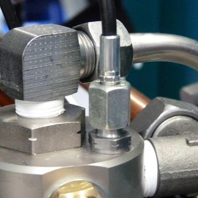

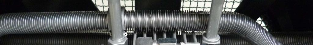
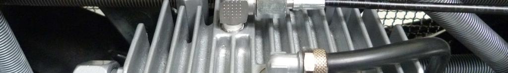

201 INTERSTAGE PRESSURE GAUGE Detailed View D Version: D - 62
202 CYLINDER HEAD TEMPERATURE MONITORING D D - 63
203 CYLINDER HEAD TEMPERATURE MONITORING Cylinder head temperature monitoring The cylinder head temperature is maintained by a temperature sensor at the cylinder head of the high pressure stage during operation. The compressor shuts off automatically when cylinder head temperature exceeds the maximum pressure of +160 C. The red warning lamp "Cylinder Head Temperature Monitoring" lights up. Possible causes of fault: Ventilation of the compressor room is not sufficient Cooling air flow not sufficient Cooling pipes contaminated D Warning Risk of burns! Allow the unit to cool before beginning troubleshooting. Version: D - 64
 Valve Head (special")
204 CYLINDER HEAD TEMPERATURE MONITORING Spare part lists Best.-Nr. / Order No. Benennung Description Display Display Sensor Sensor Ventilkopf (Spezielle Version) Valve Head (special version) D Version: D - 65
205 AIR COOLER CONNECTION KIT D D - 66
.")
206 AIR COOLER CONNECTION KIT Air cooler connection kit The Air Cooler Connection Kit provides an easy connection and a simple and time-saving installation or backfitting. The piping inside the compressor is completely installed. Just disconnect the U-connection at the outside and connect the air cooler according to the connection designation (inlet/outlet). How to connect the air cooler connection kit. Connect the outlet of the air cooler adapter to the inlet of the air cooler. Connect the inlet of the air cooler adapter to the outlet of the air cooler. Air cooler connection kit D To operate the unit without air cooler, reinstall the U-connection and the compressor is ready for use. Connecting hoses The Air Cooler Connection Kit does not include high pressure hoses. We offer different length and specification. Please ask for details. Version: D - 67
207 AIR COOLER CONNECTION KIT Spare Part List Best.-Nr. / Order No. Benennung Description Verschraubung Connection Verschraubung Straight Connection Zylinderschraube Allen Bolt U-Scheibe A8 Washer A Rippenrohrkühler 3. Stufe Finned Cooler Pipe 3rd Stage Verbindungsrohr, VA Ø8mm Connecting Pipe, Air Cooler Verbindungsrohrbogen, VA Ø10mm Connecting Pipe, Air Cooler Adapter Air Cooler Adapter Air Cooler D Version: D - 68
208 AIR COOLER CONNECTION KIT Detailed View D Version: D - 69
209 ATTACHMENT E Version: 11/12-E
 Maximum outflow: Set pressure 100-159 bar: 750 l / min Set pressure 160-350 bar: 1.")
210 OPERATING INSTRUCTION FOR SAFETY VALVE Lenhardt & Wagner GmbH An der Tuchbleiche 39 D Lampertheim Hüttenfeld Operating Instruction Safety valve Typ: SiV2 BKZ 989 TÜV.SV G.V.P CE 0091 AlMgSi1 F * Lenhardt & Wagner SiV BKZ TÜV.SV G.V.p CE 0091 AlMgSi1 F * Lenhardt & Wagner Set pressure: see mark (hand wheel on top of valve) Maximum outflow: Set pressure bar: 750 l / min Set pressure bar: l / min Suitable media: Media-resistant, non-corrosive gases The safety valve is used for protection of pressurized components, eg pipelines, pressure vessels, or the compressor itself. The hand wheel on the top of the safety valve is marked with the adjusted set pressure. 1) Identification of set pressure 2) Seal 3) Fixing screws 1 4) Venting srew (hand wheel) 5) Identification serial number 6) Socket for safety valve Safety valve with socket 1 und die Anforderungen des AD 2000 Merkblatts W7 erfüllen. Schaftlänge 70mm. The fixing screws M8 must be strength class 8.8 and meet the requirements of Merkblatt AD 2000 leaflet W7. Shaft length 70mm. Page 1
211 OPERATING INSTRUCTION FOR SAFETY VALVE In order to prevent manipulation of the set pressure, all safety valves are factory fitted with a seal. A safety valve on which the seal has been removed, must be returned before further use to the manufacturer for repair / adjustment. In addition, the safety valve has a venting device (hand wheel). In the rotation direction clockwise, the safety valve and herewith also the filter housing of the final stage could be completely vented. During normal operation, the screw is unscrewed to the upper stop anticlockwise, an integrated safety ring prevents that the screw can be completely unscrewed. If a safety valve blow off, the system must be switched off immediately and investigate the cause of the error. There are two possible reasons: 1. The safety valve is defective and blows off before the set pressure. In this case the safety valve should be submitted immediately to the manufacturer for repair or replaced with a new one. 2. The safety valve opens properly, the problem is on the system. A constant blowing of the safety valve is not permitted, the sealing seat of the valve can be damaged. The error on the system must be detected and repaired before further filling operations. The safety valve may only be used if it is ensured that the maximum flowrate of the system does not exceed the blowoff rate of the safety valve. The safety valve may only be used with the approved media. Repair work on compressors must only be performed by trained personnel. Dismantling of the safety valve Ensure that on the safety valve is no pressure. Loosen and remove the two M8 fixing bolts with a 6mm Allen key. The safety valve can now be removed by turning and simultaneously pulling out of the socket. Mounting 1. Clean the safety valve socket. 2. Oil the insert pin of the safety valve including the O-ring with 1 to 2 drops of oil. 3. Press the safety valve pin complete into the socket. 4. Fasten the safety valve with the two 8 mm allen screws into the socket (Tightening torque: 10 Nm) 5. Screw the venting screw (hand wheel) anticlockwise to its upper limit. 6. Start the System (Compressor), check installation for leaks and proper function. Page 2
 6256 85880 0 Fax: +49 (0) 6256 85880 14 Note: Use the safety valve only in a technically perfect condition, for its intended purpose, safety and danger awareness, in compliance with the")


212 OPERATING INSTRUCTION FOR SAFETY VALVE Manufacturer: Contakt: Lenhardt & Wagner GmbH An der Tuchbleiche 39 D Lampertheim Hüttenfeld Web: Tel.: +49 (0) Fax: +49 (0) Note: Use the safety valve only in a technically perfect condition, for its intended purpose, safety and danger awareness, in compliance with the operating instructions! Especially disorders which could affect safety must be remedied immediately! Notes: - The safety valve must be installed directly on the protected pressure vessel and / or the plant. - The safety valve must be installed in an upright position. - The flow area of the port must be greater than the valve opening. - Protect valve against splashes Maintenance: - The safety valve is periodically - in accordance with the currently valid Pressure Equipment Directives - to check on operation and reliability. - Refill annually lubricating oil: Oil filling position: Hole on the spacer (see arrow, Figure 1) - Oil level: Fill oil into the hole until oil comes out of the hole. Figure 1: Position for oil refill To be used lubricating oil for the safety valve: L&W Article Nr.: (content: 30 ml) Page 3
Operating Instructions... ECC - Electronic Compressor Control (if equipped)... Spare Parts Lists... Options (if equipped)... Attachment...
... Spare Parts Lists... Options (if equipped)... Attachment...") CHAPTER OVERVIEW Operating Instructions... ECC - Electronic Compressor Control (if equipped)... Spare Parts Lists... Options (if equipped)... Attachment... A B C D E Manufacturer in terms of 97/23/EC The
CHAPTER OVERVIEW Operating Instructions... ECC - Electronic Compressor Control (if equipped)... Spare Parts Lists... Options (if equipped)... Attachment... A B C D E Manufacturer in terms of 97/23/EC The
Operating Instructions
 Operating Instructions Breathing ir Compressor Version: 03/14 TBLE OF CONTENTS General Information and Technical Data General Information / Description of Warning Symbols... 4 Scope of Delivery... 5 Technical
CHAPTER OVERVIEW. Operating Instructions... Technical Data Sheet... Spare Parts Lists... Options (if equipped)... Attachment...
... Attachment...") CHPTER OVERVIEW Operating Instructions... Technical Data Sheet... Spare Parts Lists... Options (if equipped)... ttachment... B C D E Manufacturer in terms of 97/23/EC The full name and address of the manufacturer
CHPTER OVERVIEW Operating Instructions... Technical Data Sheet... Spare Parts Lists... Options (if equipped)... ttachment... B C D E Manufacturer in terms of 97/23/EC The full name and address of the manufacturer
Product Range. High performance and economic high pressure solutions Made in Germany
 Product Range Purification Storage Filling Panels Nitrox/Trimix High performance and economic high pressure solutions Made in Germany www.lw-compressors.com 2 Lenhardt & Wagner Solid Growth Lenhardt &
AIR COMPRESSOR OPERATING INSTRUCTION AND PARTS LIST
 AIR COMPRESSOR OPERATING INSTRUCTION AND PARTS LIST OIL-LESS TYPE IMPORTANT: PLEASE READ CAREFULLY BEFORE STARTING OPERATIONS. THE CONTENTS ARE FOR GENERAL INFORMATION OF ALL THE SIMILAR MODELS. Record
VERTICAL AIR COMPRESSORS
 VERTICAL AIR COMPRESSORS MODEL NO: VE15C150, VE18C150, VE25C150 PART NO: 2226010, 2226020, 2226025 OPERATION & MAINTENANCE INSTRUCTIONS LS0715 INTRODUCTION Thank you for purchasing this CLARKE Vertical
VERTICAL AIR COMPRESSORS
 VERTICAL AIR COMPRESSORS MODEL NO: VE11C150, VE15C150, VE18C150 PART NO: 2226005, 2226000, 2226015 OPERATION & MAINTENANCE INSTRUCTIONS LS0615 INTRODUCTION Thank you for purchasing this CLARKE Vertical
200L BELT DRIVEN AIR COMPRESSOR
 200L BELT DRIVEN AIR COMPRESSOR MODEL NO: BOXER 14/200 PART NO: 2245215 OPERATION & MAINTENANCE INSTRUCTIONS ORIGINAL INSTRUCTIONS LS0118 ISS 4 INTRODUCTION Thank you for purchasing this CLARKE 200L Belt
Code AWC20HP Air Compressor
 Code 951816 AWC20HP Air Compressor Index of Contents Index of Contents 02 Declaration of Conformity 02 What s Included 03 Safety Precautions 03 Specifications (AWC20HP Air Compressor) 04 Assembly Instructions
Budget Range Operators Handbook
 Budget Range Operators Handbook BAMBI AIR COMPRESSORS LTD 152 Thimble Mill Lane Heartlands Birmingham B7 5HT United Kingdom Tel: 0121 322 2299 Fax: 0121 322 2297 Email: sales@bambi-air.co.uk www.bambi-air.co.uk
SPECIFICATIONS Type: Twin stack, single phase Tank: 4 gallon Air Output: PSI; PSI Max PSI: 125 PSI HP: 1.
 2 GALLON TWIN STACK AIR COMPRESSOR Model: 9526 DO NOT RETURN TO STORE. Please CALL 800-348-5004 for parts and service. CALIFORNIA PROPOSITION 65 WARNING: You can create dust when you cut, sand, drill or
24L OIL FREE AIR COMPRESSOR MODEL NO: TIGER 7/250 PART NO: OPERATION & MAINTENANCE INSTRUCTIONS LS10/13
 24L OIL FREE AIR COMPRESSOR MODEL NO: TIGER 7/250 PART NO: 2244030 OPERATION & MAINTENANCE INSTRUCTIONS LS10/13 INTRODUCTION Thank you for purchasing this product. Before attempting to use this product,
30T A/Manual Hydraulic Shop Press
 30T A/Manual Hydraulic Shop Press Operation Manual 1 1. Important Information 1.1 Safety Information 1.1.1 Hazard Symbols Used in the Manuals This manual includes the hazard symbols defined below when
100L AIR COMPRESSOR MODEL NO: TIGER 16/1010 PART NO: OPERATION & MAINTENANCE INSTRUCTIONS LS01/13
 100L AIR COMPRESSOR MODEL NO: TIGER 16/1010 PART NO: 2244025 OPERATION & MAINTENANCE INSTRUCTIONS LS01/13 INTRODUCTION Thank you for purchasing this product. Before attempting to use this product, please
50L ENGINE DRIVEN AIR COMPRESSOR MODEL NO: XPPV11 & XPP15 RANGE
 50L ENGINE DRIVEN AIR COMPRESSOR MODEL NO: XPPV11 & XPP15 RANGE OPERATION & MAINTENANCE INSTRUCTIONS ORIGINAL INSTRUCTIONS LS0118 - ISS 1 INTRODUCTION Thank you for purchasing this CLARKE compressor which
50L BELT DRIVEN AIR COMPRESSOR
 50L BELT DRIVEN AIR COMPRESSOR MODEL NO: BOXER 14/50P PART NO: 2245200, 2245203 OPERATION & MAINTENANCE INSTRUCTIONS ORIGINAL INSTRUCTIONS LS0118 - ISS 4 INTRODUCTION Thank you for purchasing this CLARKE
24L AIR COMPRESSOR MODEL NO: TIGER 8/260 PART NO:
 24L AIR COMPRESSOR MODEL NO: TIGER 8/260 PART NO: 1499490 OPERATION & MAINTENANCE INSTRUCTIONS ORIGINAL INSTRUCTIONS LS0918 - ISS 2 INTRODUCTION Before attempting to use this product, please read this
Type BBS-03, BBS-05, BBS-06, BBS-25
 Type BBS-03, BBS-05, BBS-06, BBS-25 Sterile connection elements Sterile Verbindungselemente Raccords union stériles Operating Instructions Bedienungsanleitung Manuel d utilisation 1. THE OPERATING INSTRUCTIONS
AIR COMPRESSOR OPERATION & MAINTENANCE INSTRUCTIONS MODEL NO: CHAMP 3 PART NO: LS0115
 AIR COMPRESSOR MODEL NO: CHAMP 3 PART NO: 2225222 OPERATION & MAINTENANCE INSTRUCTIONS LS0115 INTRODUCTION Thank you for purchasing this CLARKE Air Compressor. Please read this manual fully before use
2 GALLON TWIN STACK AIR COMPRESSOR W/ HOSE REEL
 2 GALLON TWIN STACK AIR COMPRESSOR W/ HOSE REEL Model: 52024 CALIFORNIA PROPOSITION 65 WARNING: You can create dust when you cut, sand, drill or grind materials such as wood, paint, metal, concrete, cement,
Installation and operating manual. Pneumatic control station LK product no: PCS 1-10
 LK product no: PCS 1-10 Article no: 74503 Revision:8 Article no: 74503 Revision: 8 2 (23) Contents 1. General information... 5 2. Safety precautions... 5 2.1 Significance of symbols... 5 2.2 Explanatory
Pneumatic proportional controller Types M Types FM Function tested for use of the float in Ex-zone 0
 Operating Manual LTIA5E Pneumatic proportional controller Types M Types FM Function tested for use of the float in Ex-zone 0 Contents 1. Safety Instructions 2. Conformity to standards 3. Technical data
24L AIR COMPRESSOR MODEL NO: TIGER 11/250 PART NO: OPERATION & MAINTENANCE INSTRUCTIONS LS01/13
 24L AIR COMPRESSOR MODEL NO: TIGER 11/250 PART NO: 2244010 OPERATION & MAINTENANCE INSTRUCTIONS LS01/13 INTRODUCTION Thank you for purchasing this product. Before attempting to use this product, please
Operating and maintenance manual Filter and reducing station Series / 1.0
 Operating and maintenance manual Filter and reducing station Series 961 04.2017 / 1.0 Original instructions ARCA Regler GmbH. All rights reserved. Cover picture background: Freepik.com ARCA Regler GmbH
AMP Oil Free Manual AMP 50-8-TC AMP 50-6-D AMP General User and Maintenance Instructions
 AMP Oil Free Manual AMP 50-8-TC AMP 50-6-D AMP 50-24 General User and Maintenance Instructions Silentaire Technology 8614 Veterans Memorial Dr. Houston, TX 77088 800-972-7668 Fax 832-327-0669 www.silentaire.com
Mounting and Operating Instructions EB 2558 EN. Self-operated Pressure Regulators. Type Pressure Build-up Regulator
 Self-operated Pressure Regulators Type 2357-31 Pressure Build-up Regulator with safety function and integrated excess pressure valve Type 2357-31 with non-return unit at port C Ports A and B with soldering
MODEL NUMBER: PSI AIR SOURCE KIT 200 PSI Compressor on 2.0 Gallon 200 PSI Air Tank
 IMPORTANT SAFETY INSTRUCTIONS CAUTION - To reduce risk of electrical shock or Electrocution: MODEL NUMBER: 20008 200 PSI AIR SOURCE KIT 200 PSI Compressor on 2.0 Gallon 200 PSI Air Tank IMPORTANT: It is
24L AIR COMPRESSOR OPERATION & MAINTENANCE INSTRUCTIONS MODEL NO: RANGER 7/240 PART NO: LS0913
 24L AIR COMPRESSOR MODEL NO: RANGER 7/240 PART NO: 2242000 OPERATION & MAINTENANCE INSTRUCTIONS LS0913 INTRODUCTION Thank you for purchasing this CLARKE 24L Air Compressor. Please read this manual fully
COMPRESSOR OPERATION & MAINTENANCE INSTRUCTIONS MODEL NO: WARRIOR 55 PART NO: (110V) , (230V) , LS0512
 , (230V) , LS0512") COMPRESSOR MODEL NO: WARRIOR 55 PART NO: (110V) 2323010, (230V) 2322020, OPERATION & MAINTENANCE INSTRUCTIONS LS0512 INTRODUCTION Thank you for purchasing this CLARKE Compressor. Before attempting to use
COMPRESSOR MODEL NO: WARRIOR 55 PART NO: (110V) 2323010, (230V) 2322020, OPERATION & MAINTENANCE INSTRUCTIONS LS0512 INTRODUCTION Thank you for purchasing this CLARKE Compressor. Before attempting to use
Instruction Manual ATLANTIC 100
 Page 1 This manual contains operating instructions and maintenance schedules for the high pressure breathing air compressors. Operators must read and understand all information inside the manual. ATTENTION.
MODEL NUMBER: M20005 AIR SOURCE KIT. 30% Duty Compressor on. 2.0 Gallon Air Tank SAVE THIS MANUAL FOR FUTURE REFERENCE
 MODEL NUMBER: M20005 AIR SOURCE KIT 30% Duty Compressor on 2.0 Gallon Air Tank SAVE THIS MANUAL FOR FUTURE REFERENCE USER MANUAL IMPORTANT SAFETY INSTRUCTIONS CAUTION - To reduce risk of electrical shock
Mounting and Operating Instructions EB 3007 EN. Self-operated Pressure Regulators. Differential Pressure Regulators (opening) Type Type 42-25
 Type Type 42-25") Self-operated Pressure Regulators Differential Pressure Regulators (opening) Type 42-20 Type 42-25 Type 42-20 Differential Pressure Regulator Type 42-25 Differential Pressure Regulator Mounting and Operating
Self-operated Pressure Regulators Differential Pressure Regulators (opening) Type 42-20 Type 42-25 Type 42-20 Differential Pressure Regulator Type 42-25 Differential Pressure Regulator Mounting and Operating
User Guide for. UTR Turbo Air Lappers Pneumatic Air Grinders & Lappers UTR-30, UTR-70, UR , ,
 User Guide for UTR Turbo Air Lappers Pneumatic Air Grinders & Lappers UTR-30, UTR-70, UR-120 8502250, 8502245, 8502251 We thank you for choosing our products. This guide provides information on general
IMPORTANT SAFETY INSTRUCTIONS
 IMPORTANT SAFETY INSTRUCTIONS CAUTION - To reduce risk of electrical shock: - Do not disassemble. Do not attempt repairs or modifications. Refer to qualified service agencies for all service and repairs.
AC1810 / AC1810-A TECHNICAL SPECIFICATIONS. Operating Pressure psi ( kgs/cm²) [AC1810] Displacement. Net Weight
![AC1810 / AC1810-A TECHNICAL SPECIFICATIONS. Operating Pressure psi ( kgs/cm²) [AC1810] Displacement. Net Weight](/thumbs/83/88369739.jpg "AC1810 / AC1810-A TECHNICAL SPECIFICATIONS. Operating Pressure psi ( kgs/cm²) [AC1810] Displacement. Net Weight") Technical Specifications Operating Instructions Maintenance Information Troubleshooting Guide Parts Diagrams AC1810 / AC1810-A THE EVOLUTION OF PERFECTION CAUTION: Before attempting to use or service this
Technical Specifications Operating Instructions Maintenance Information Troubleshooting Guide Parts Diagrams AC1810 / AC1810-A THE EVOLUTION OF PERFECTION CAUTION: Before attempting to use or service this
100C Air Compressor Kit
 10010 100C Air Compressor (standard mounting bracket, CE Spec) 10014 100C Air Compressor (no leader hose or check valve, CE Spec) 10016 100C Air Compressor (with Omega Bracket, CE Spec) IMPORTANT: It is
80 Litre Suction Oil Drainer
 80 Litre Suction Oil Drainer Please dispose of packaging for the product in a responsible manner. It is suitable for recycling. Help to protect the environment, take the packaging to the local amenity
Auto-Rewind Hose Reels INSTRUCTION MANUAL FOR OXY-LPG MODEL
 Auto-Rewind Hose Reels INSTRUCTION MANUAL FOR OXY-LPG MODEL Introduction Thank you for purchasing a Retracta Auto Rewind Hose Reel. The Retracta range of hose reels are a breakthrough in industrial quality
Manual Actuated Boiler Blowdown Valves
 Manual Actuated Boiler Blowdown Valves Installation and Maintenance Instructions 1. Safety information 2. General product information 3. Installation 4. Operation 5. Maintenance 6. Spare parts p.1 1. Safety
Safety instructions and operating manual
 5-Master Safety instructions and operating manual TBF-PyroTec GmbH Lichterfelder Str. 5 A 21502 Geesthacht Tel.: + 49 (0)4152 157 9950 Fax: + 49 (0)4152 157 9951 Flame projector 5-Master Safety instructions
Measurement accessories METPOINT OCV for the measurement in systems up to 40 bar
 EN - english Instructions for installation and operation Measurement accessories METPOINT OCV for the measurement in systems up to 40 bar Dear customer, Thank you for deciding in favour of the METPOINT
444C DUAL PERFORMANCE VALUE PACK
 (Chrome) PART NO. 44432 IMPORTANT: It is essential that you and any other operator of this product read and understand the contents of this manual before installing and using this product. SAVE THIS MANUAL
420C AIR COMPRESSOR KIT PART NO C AIR COMPRESSOR KIT PART NO
 420C AIR COMPRESSOR KIT PART NO. 42042 460C AIR COMPRESSOR KIT PART NO. 46043 420C 460C IMPORTANT: It is essential that you and any other operator of this product read and understand the contents of this
Modular valve block. Operating manual Series MVB 100/200. Version BA EN Print-No TR MA DE Rev001
 Modular valve block Operating manual Series MVB 100/200 Version BA-2016.04.20 EN Print-No. 300 627 TR MA DE Rev001 ASV Stübbe GmbH & Co. KG Hollwieser Straße 5 32602 Vlotho Germany Phone: +49 (0) 5733-799-0
AIR COMPRESSOR. Failure to follow all instructions as listed below may result in electrical shock, fire, and/or serious personal injury.
 2 GALLON AIR COMPRESSOR Model: 7517 DO NOT RETURN TO STORE. Please CALL 800-348-5004 for parts and service. CALIFORNIA PROPOSITION 65 WARNING: You can create dust when you cut, sand, drill or grind materials
Pressure booster combination DPA-CRVZS. Operating instructions a [ ]
![Pressure booster combination DPA-CRVZS. Operating instructions a [ ]](/thumbs/88/116599651.jpg "Pressure booster combination DPA-CRVZS. Operating instructions a [ ]") Pressure booster combination en Operating instructions 8074546 2017-07a [8074548] Original instructions -EN Identification of hazards and instructions on how to prevent them: Danger Immediate dangers which
Pressure booster combination en Operating instructions 8074546 2017-07a [8074548] Original instructions -EN Identification of hazards and instructions on how to prevent them: Danger Immediate dangers which
200 PSI COMPRESSORS - MODEL NUMBERS
 200 PSI COMPRESSORS - MODEL NUMBERS 380C AIR COMPRESSOR KIT PART NO. 38033 480C AIR COMPRESSOR KIT PART NO. 48043 380C 480C IMPORTANT: It is essential that you and any other operator of this product read
SC6H OIL-LESS AIR COMPRESSOR
 SC6H OIL-LESS AIR COMPRESSOR OWNER S MANUAL FOR YOUR SAFETY PLEASE READ THESE INSTRUCTIONS CAREFULLY AND RETAIN THEM FOR FUTURE USE. MAIN COMPONENTS 1. ON/OFF switch 2. Outlet valve 3. Regulating valve
250C-IG COMPRESSOR KIT 12V PART NO C-IG COMPRESSOR KIT 24V PART NO
 250C-IG COMPRESSOR KIT 12V PART NO. 25050 250C-IG COMPRESSOR KIT 24V PART NO. 25058 IMPORTANT: It is essential that you and any other operator of this product read and understand the contents of this manual
OPERATION MANUAL NTF-15
 OPERATION MANUAL NTF-15 Nitrogen Tire Filling Valve Stem Caps (Qty=200) Order P/N 436075 RTI Technologies, Inc 10 Innovation Drive York, PA 17402 800-468-2321 www.rtitech.com 035-81235-00 (Rev B) TABLE
TECHNICAL DATA MAINTENANCE AIR COMPRESSOR MODEL G-1
 Dry 131h 1. DESCRIPTION The Viking Model G-1 Maintenance Air Compressor is an electric motor-driven, aircooled, single-stage, oil-less compressor. The unit is equipped with a check valve and provides a
250C-IG COMPRESSOR KIT 12V PART NO C-IG COMPRESSOR KIT 24V PART NO
 250C-IG COMPRESSOR KIT 12V PART NO. 25050 250C-IG COMPRESSOR KIT 24V PART NO. 25058 IMPORTANT: It is essential that you and any other operator of this product read and understand the contents of this manual
KTM OM-2 SPLIT BODY FLOATING BALL VALVES INSTALLATION AND MAINTENANCE INSTRUCTIONS
 Before installation these instructions must be fully read and understood SECTION 1 - STORAGE 1.1 Preparation and preservation for storage All valves should be properly packed in order to protect the parts
97C COMPRESSOR KIT 12V PART NO C COMPRESSOR KIT 24V PART NO C COMPRESSOR KIT PART NO
 97C COMPRESSOR KIT 12V PART NO. 00097 97C COMPRESSOR KIT 24V PART NO. 02497 98C COMPRESSOR KIT PART NO. 00098 97C 98C IMPORTANT: It is essential that you and any other operator of this product read and
200 PSI FAST-FILL AIR SOURCE KIT
 200 PSI FAST-FILL AIR SOURCE KIT 55% Duty Compressor on 2.0 Gallon Air Tank PART NO. 20007 IMPORTANT: It is essential that you and any other operator of this product read and understand the contents of
200 PSI HIGH-FLOW AIR SOURCE KIT
 200 PSI HIGH-FLOW AIR SOURCE KIT 50% Duty Compressor on 2.0 Gallon Air Tank PART NO. 20008 IMPORTANT: It is essential that you and any other operator of this product read and understand the contents of
OPERATING MANUAL CHEMTRAC 840M MANUAL RETRACTABLE PROCESS HOLDER
 OPERATING MANUAL CHEMTRAC 840M MANUAL RETRACTABLE PROCESS HOLDER Table of contents 1 Security and safety measures... 5 1.1 General safety instructions... 5 1.2 Intended use... 5 1.3 Danger zones and residual
Mobile High Pressure Compressor Unit for Compressing Air and Breathing Air. PE 250-TE with compressor control (optional equipment)
") Mobile High Pressure Compressor Unit for Compressing Air and Breathing Air Types: PE 200-TE PE 250-TE PE 300-TE Production status: F02 PE 250-TE with compressor control (optional equipment) General Medium
Mobile High Pressure Compressor Unit for Compressing Air and Breathing Air Types: PE 200-TE PE 250-TE PE 300-TE Production status: F02 PE 250-TE with compressor control (optional equipment) General Medium
400C & 450C DUAL PERFORMANCE VALUE PACKS
 (Chrome) PART NO. 40013 (Silver) PART NO. 45012 (Chrome) PART NO. 45013 IMPORTANT: It is essential that you and any other operator of this product read and understand the contents of this manual before
Type /2-Way Globe Valve 3/2-Wege-Geradsitzventil Vanne à siège droit 3/2 voies Operating Instructions Bedienungsanleitung Manuel d utilisation
 3/2-Way Globe Valve 3/2-Wege-Geradsitzventil Vanne à siège droit 3/2 voies Operating Instructions Bedienungsanleitung Manuel d utilisation We reserve the right to make technical changes without notice.
MODEL 200 KNIFE GATE VALVES INSTALLATION & MAINTENANCE MANUAL
 MODEL 200 KNIFE GATE VALVES INSTALLATION & MAINTENANCE MANUAL Index 1. List of components / General arrangement 2. Description 3. Handling 4. Installation 5. Actuators / Operation 6. Maintenance a. Changing
400H HARDMOUNT AIR COMPRESSOR KIT PART NO H HARDMOUNT AIR COMPRESSOR KIT PART NO
 400H HARDMOUNT AIR COMPRESSOR KIT PART NO. 40042 450H HARDMOUNT AIR COMPRESSOR KIT PART NO. 45042 400H 450H IMPORTANT: It is essential that you and any other operator of this product read and understand
MD R a n g e O p e r a t o r s H a n d b o o k
 MD R a n g e O p e r a t o r s H a n d b o o k Covering Models:- MD35/20 MD75/80 MD75/0 MD75/0V MD75/250 MD75/250V MD0/500 MD225/1000 BAMBI AIR COMPRESSORS LTD 2 Thimble Mill Lane Heartlands Birmingham
OPERATION MANUAL NTF-60 Plus
 OPERATION MANUAL NTF-60 Plus Nitrogen Tire Filling Valve Stem Caps (Qty=200) Order P/N 436075 RTI Technologies, Inc 10 Innovation Drive York, PA 17402 800-468-2321 www.rtitech.com 035-81264-00 (Rev A)
Pneumatic switch module 3/2-way valve (On/Off) Types P Types FP Function tested for use of the float in Ex-zone 0
 Types P Types FP Function tested for use of the float in Ex-zone 0") Operating Manual LTIA3E Pneumatic switch module 3/2-way valve (On/Off) Types P Types FP Function tested for use of the float in Ex-zone 0 Contents 1. Safety Instructions 2. Conformity to standards 3. Technical
Operating Manual LTIA3E Pneumatic switch module 3/2-way valve (On/Off) Types P Types FP Function tested for use of the float in Ex-zone 0 Contents 1. Safety Instructions 2. Conformity to standards 3. Technical
Instruction manual. for. high purity gas pigtails 200 bar / 300 bar
 Instruction manual for high purity gas pigtails 200 bar / 300 bar Contents Contents... 2 1. Preface... 3 1.1 Overview... 3 1.2 General... 3 1.3 Intended use... 4 1.4 Personnel requirements... 4 2. For
SF SERIES CNG COMPRESSOR MODEL HF-4MH. 4 Nm3/Hour Displacement OPERATION MANUAL
 SF SERIES CNG COMPRESSOR MODEL HF-4MH 4 Nm3/Hour Displacement OPERATION MANUAL 1 Content 1. General Description...3 2. Main technical parameters...3 3. Structural principle...4 3.1Main structure...4 3.2Compressor
Flowmeter. Original operating manual DFM
 Flowmeter Original operating manual Series DFM 165 350 Version BA-2016.08.09 EN Print-No. 300 458 TR MA DE Rev002 ASV Stübbe GmbH & Co. KG Hollwieser Straße 5 32602 Vlotho Germany Phone: +49 (0) 5733-799-0
Ball valve. Operating instructions for series. Version BA Print-No TR MA DE Rev001
 Ball valve Operating instructions for series Version BA-2016.02.05 Print-No. 300 587 TR MA DE Rev001 We reserve the right to make technical changes. Read carefully before use. Save for future use. ASV
Siphon vessel / Priming aid
 Manufacturer: sera GmbH sera-straße 1 34376 Immenhausen Germany Tel.: +49 5673 999-00 Fax: +49 5673 999-01 info@sera-web.com Keep the operating manual for future use! Record the exact type and serial number
neska High-Speed Handpiece P320
 neska High-Speed Handpiece Instruction Manual for the ENESKA High-Speed Handpiece Made and sold by: JOISTEN & KETTENBAUM GmbH & Co. KG Surface finishing PO Box 10 03 52 D-51403 Bergisch Gladbach Asselborner
Components for air preparation and pressure adjustment. OUT port position ( ) connected Rear side. of IN port. Air tank. directly.
 connected Rear side. of IN port. Air tank. directly.") Components preparation and pressure adjustment ABP Overview ABP is a component that enables boosting by s only up to twice primary pressure (.0MPa max.) in combination with using air tank but not using
Components preparation and pressure adjustment ABP Overview ABP is a component that enables boosting by s only up to twice primary pressure (.0MPa max.) in combination with using air tank but not using
1. PARTS INTRODUCTION ELECTRICAL NOTES INSTALLATION 5/6. 5. START UP 6/7. 6. MAINTENANCE 7/8/9. 7. PRESSURE SWITCH ADJUSTMENTS 9/10.
 CONTENTS 1. PARTS 3. 2. INTRODUCTION 4. 3. ELECTRICAL NOTES 5. 4. INSTALLATION 5/6. 5. START UP 6/7. 6. MAINTENANCE 7/8/9. 7. PRESSURE SWITCH ADJUSTMENTS 9/10. 8. ELECTRICAL CONNECTIONS 10/11. 9. SPECIFICATIONS
Pressure relief valve
 Pressure relief valve Operating manual Series DHV 718 Version BA-2016.01.11 EN Print-No. 300 524 TR MA DE Rev001 ASV Stübbe GmbH & Co. KG Hollwieser Straße 5 32602 Vlotho Germany Phone: +49 (0) 5733-799-0
Series IRV1000/2000/3000
 CAT.ES60-16 A Regulator Series /2000/3000 Allows adjustment of vacuum line pressure Regulator Series /2000/3000 3 sizes offered in the series Variations have been expanded to three sizes from only one
RARS5000 AIR BODY SAW OWNER S OPERATING MANUAL
 RARS5000 AIR BODY SAW OWNER S OPERATING MANUAL DESCRIPTION 1. No mar 2. No mar tip 3. Housing grip 4. Trigger 5. Air inlet 6. Air inlet plug 7. Plastic board Important! It is essential that you read the
Instructions for: COMPRESSORS 270ltr belt drive 5.5 / 7.5 hp
 Instructions for: COMPRESSORS 270ltr belt drive 5.5 / 7.5 hp 3ph 2-stage model No's: SAC42755BLN, SAC72775BLN Thank you for purchasing a Sealey product. Manufactured to a high standard this product will,
High Pressure Breathing Air Compressors NAUTILUS MINI
 High Pressure Breathing Air Compressors NAUTILUS MINI 1. INTRODUCTION This manual contains operating instructions and maintenance schedule for the high pressure breathing air compressor unit NAUTILUS MINI
Pressure relief valve
 Pressure relief valve Operating manual Series DHV 712 R Version BA-2016.01.19 EN Print-No. 300 472 TR MA DE Rev001 ASV Stübbe GmbH & Co. KG Hollwieser Straße 5 32602 Vlotho Germany Phone: +49 (0) 5733-799-0
Operating Instructions. Ball valve fitting according to ZB For pressure transmitter VEGABAR 82. Document ID: 50027
 Operating Instructions Ball valve fitting according to ZB 2553 For pressure transmitter VEGABAR 82 Document ID: 50027 Contents Contents 1 About this document 1.1 Function... 3 1.2 Target group... 3 1.3
AC558RB AC7011RB. operation manual
 AC558RB AC7011RB operation manual table of contents Introduction 4 Using the Operators Manual Specifications 4 Specifications Product Identification 5 Record Identification Numbers Safety 6 Safety Instructions
OPERATING INSTRUCTIONS
 0/05 OPERATING INSTRUCTIONS for gas pressure regulators PN0 with integrated slam shut valve (SSV) and integrated limited capacity safety relief valve (RV) MR 25 F0, MR 25 SF0 p e 20 kpa - 0 MPa (0,2-0
Declaration of Conformity as per Directive 97/23/EC
 Declaration of Conformity as per Directive 97/23/EC The manufacturer declares that:, 47906 Kempen, Germany Multi-way diverting valves Series 29a and Series 29b, with packing with lever 1. The valves are
K Page 1 of 48 Air Intake - Pg. 17
 K532-53168 Page 1 of 48 Air Intake - Pg. 17 Ref # Part Number Qty Description 24 25 041 06-S 1 Gasket, elbow 25 48 054 09 1 Elbow, air cleaner Discontinued not available at Kohler Co. 35 277116-S 1 Brace,
3/8" Dr. Air Butterfly Impact Wrench
 8192106 3/8" Dr. Air Butterfly Impact Wrench Owner s Manual Read and understand all instructions before use. Retain this manual for future reference. Specifications Construction: Polished aluminum and
Model PSI Compressor with 3-Gallon Air Tank 12VDC
 Model 6350 150 PSI Compressor with 3-Gallon Air Tank 12VDC IMPORTANT: It is essential that you and any other operator of this product read and understandd the contents of this manual before installing
Translation of the original Operating Instructions for HKS rubber compensators
 Because of their flexible elements and mechanisms, HKS rubber compensators are susceptible to damage of all types and adverse loads in operation. For reliable operation of a compensator and, thus, the
MANUAL SEALLESS STEEL STRAPPING TOOL MODEL A
 OPERATION MANUAL / SPARE PARTS LIST MANUAL SEALLESS STEEL STRAPPING TOOL MODEL A337.0001 13.1912.01 13191201.en/MAS/ 10.02 INDEX PAGE 1 SAFETY INSTRUCTIONS 2 2 WARRANTY CONDITIONS AND LIABILITY 4 3 APPROPRIATE
Declaration of Conformity as per Directive 97/23/EC
 Declaration of Conformity as per Directive 97/23/EC The manufacturer declares that:, 47906 Kempen, Germany Continuous, inline sampling valves Series 27f, with packing Operate with either; Star lever, or
Operation Manual Air Saver Unit ASV5000 Series
 9IM-V066-b Operation Manual Air Saver Unit ASV5000 Series Thank you for your choice of Kuroda Pneumatics LTDs product on this time. Please read this operation manual carefully and use the product correctly.
New Product. Air Consumption 70% Down. Precision Regulator Air Saving Type. RPE Series PRECISION REGULATOR RPE SERIES CC-1072A
 Air Consumption 70% Down New Product Precision Regulator Air Saving Type RPE Series PRECISION REGULATOR RPE SERIES Large Air Saving CC-1072A Air Consumption 70% Down. New Type Eco-friendly Precision Regulator
Type 3709 Pneumatic Lock-up Valve. Translation of original instructions. Mounting and Operating Instructions EB 8391 EN
 Type 3709 Pneumatic Lock-up Valve Translation of original instructions Mounting and Operating Instructions EB 8391 EN Edition July 2017 Note on these mounting and operating instructions These mounting
Installation & Operation Manual Proven Quality since 1892
 Content 1. ERIKS operating companies 2. Product description 3. Requirements for maintenance staff 4. Transport and storage 5. Function 6. Application 7. Installation 8. Maintenance 9. Service and repair
Freedom8 ShoeBox Compressor Manual
 Freedom8 ShoeBox Compressor Manual Warning!! This product is not a toy! Use or misuse can cause severe injury or death! Use only with adult supervision. This unit is only to be used with tanks, hoses and
310 SERIES TILT-TO-LOAD ROTATOR. The Specialist In Drum Handling Equipment
 OPERATOR S MANUAL FOR MORSE TILT-TO-LOAD DRUM ROTATOR SAFETY INFORMATION: While Morse Manufacturing Co. drum handling equipment is engineered for safety and efficiency, a high degree of responsibility
Airmate TS1.5/6 Oil-less Air Compressor
 Please dispose of packaging for the product in a responsible manner. It is suitable for recycling. Help to protect the environment, take the packaging to the local amenity tip and place into the appropriate
OPERATING AND MAINTENANCE MANUAL GOLD LINE EXTRACTION CLEANERS M14-M26
 OPERATING AND MAINTENANCE MANUAL GOLD LINE EXTRACTION CLEANERS M14-M26 Made For: Spitwater Australia Pty Ltd 953 Metry St North Albury, NSW, Australia WARNING: FAILURE TO FOLLOW OPERATING, SAFETY AND MAINTENANCE
User Instruction Manual
 User Instruction Manual 4500 psi Air Compressor Ver 2, 1.18 Contents Parts Included...3 Assembly Instructions...3-5 Operation Instructions...6-7 Oil Change Intervals...8 Air Filter Replacement...9 Setting
PENCOFLEX COUPLING ASSEMBLY AND MAINTENANCE
 ATEX 1-ASSEMBLY - During the final boring of couplings supplied with a pre-bore, make sure that the plate to be machined is centered correctly on its larger diameter. In this way, the bore will be absolutely
Type 0404 / /2-way solenoid valve 2/2-Wege-Magnetventil Électrovanne 2/2 voies Operating Instructions Bedienungsanleitung Manuel d utilisation
 Type 0404 / 5404 2/2-way solenoid valve 2/2-Wege-Magnetventil Électrovanne 2/2 voies Operating Instructions Bedienungsanleitung Manuel d utilisation 1 OPERATING INSTRUCTIONS The operating instructions