USER GUIDE, VOL.2.0 MYOGRAPH SYSTEM - 112PP/114P
|
|
|
- Oscar Craig
- 5 years ago
- Views:
Transcription


1 USER GUIDE, VOL.2.0 MYOGRAPH SYSTEM - 112PP/114P


2
3 CONTENTS CHAPTER Pressure Myograph 114P overview Pressure Myograph 112PP overview 5 CHAPTER 2 - SET-UP THE PRESSURE MYOGRAPH Adjustment of the Glass Cannulas way valve adjustments 8 CHAPTER 3 - EXPERIMENTAL SET-UP way valve adjustments 9 CHAPTER 4 - CLEANING AND MAINTENANCE Cleaning the 114P Pressure Myograph Cleaning the 112PP Pressure Myograph Maintenance of Pressure Myograph Chamber pipes Maintenance of force transducer Maintenance of Pressure transducer and Glass Cannulas 26 APPENDIX 1 - BUFFER RECIPES 27 Physiological Saline Solution (PSS) 27 High potassium Physiological Saline Solution (KPSS) 29


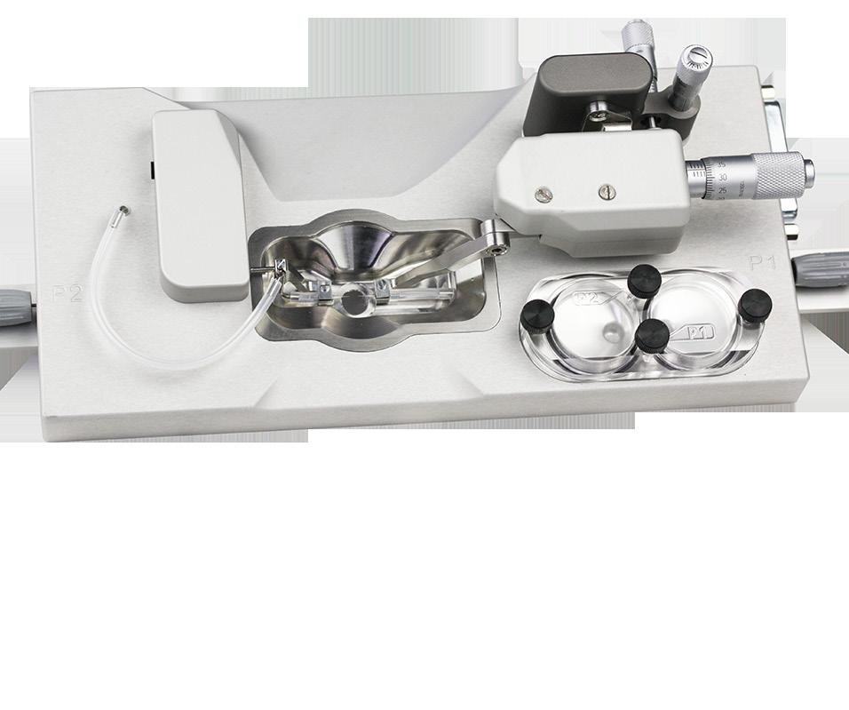
4 CHAPTER PRESSURE MYOGRAPH 114P OVERVIEW Micropositioner for vertical adjustment of Glass Cannulas Micropositioner for horizontal adjustment of Glass Cannulas Outlet pressure transducer connection pipe Force Transducer housing 25 pin serial port for communication with Pressure Interface 3-way Inlet valve 3-way Outlet valve Outlet pressure transducer Force transducer pin Inlet pressure transducer Screw for adjusting the P2 arm in the vertical direction Fixation plate for left Glass Cannula Fixation plate for right Glass Cannula Outlet connecting pipe Perfusion inlet pipe Silicone tube connecting perfusion outlet pipe and right Glass Cannula Left Glass Cannula Chamber Window Right Glass Cannula Silicone tube connecting perfusion inlet pipe and right Glass Cannula 4 Figure 1.1 Pressure Myograph - 114P with close-up detail of the chamber
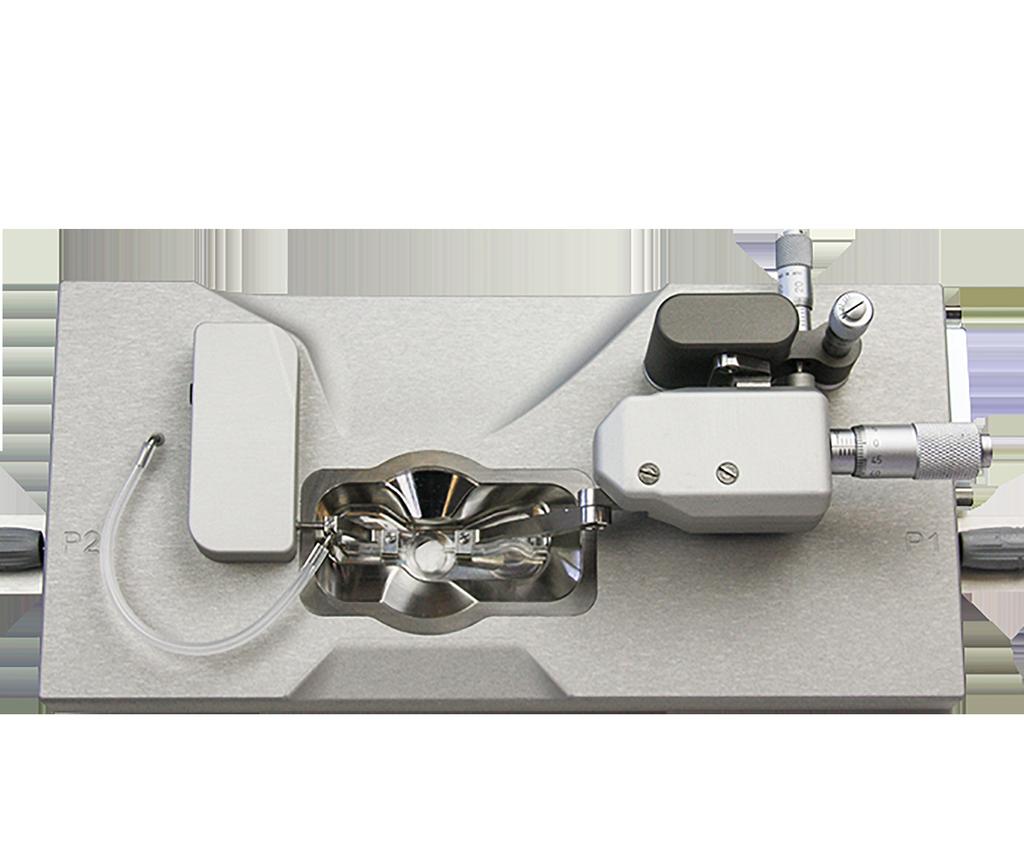
5 1.2 PRESSURE MYOGRAPH 112PP OVERVIEW Micropositioner for vertical adjustment of Glass Cannulas Micropositioner for horizontal adjustment of Glass Cannulas Outlet pressure transducer connection pipe Force Transducer housing 25 pin serial port for communication with Pressure Interface 3-way Inlet valve 3-way Outlet valve Outlet pressure transducer Force transducer pin Pulsation Chamber 2 Pressure Release screw for Pulsation Chamber1 Pulsation Chamber 1 Pressure Release screw for Pulsation Chamber2 Screw for adjusting the P2 arm in the vertical direction Fixation plate for left Glass Cannula Fixation plate for right Glass Cannula Outlet connecting pipe Perfusion inlet pipe Silicone tube connecting perfusion outlet pipe and right Glass Cannula Left Glass Cannula Chamber Window Right Glass Cannula Silicone tube connecting perfusion inlet pipe and right Glass Cannula Figure 1.2 Pressure Myograph - 112PP with close-up detail of the chamber 5
6 CHAPTER 2 - SET-UP THE PRESSURE MYOGRAPH 2.1 ADJUSTMENT OF THE GLASS CANNULAS Adjustment of the Glass Cannulas is divided into a pre-experimental alignment and general adjustments done during mounting of a blood vessel or when running an experiment. General adjustments (see figure 2.1) General adjustments are performed using the three micropositioners on top of the 114P and 112PP Pressure Myograph (Figure 2.1). The horizontal micropositioner A, is used to define the length between the two Glass Cannulas and thereby the horizontal stretch of the mounted blood vessel. The vertical micropositioner B, is used to adjust the vertical position of the right Glass Cannula and thereby the vertical position of the mounted blood vessel. The horizontal micropositioner C, is used to adjust the right Glass Cannula from side to side in the horizontal plane and thereby making sure that the two cannula tips are exactly aligned across each other in the X-Y-Z plane. Pre-experimental alignment To make the general adjustments as easy as possible during an experiment, it is important to make an alignment of the Glass Cannulas prior to the mounting of the blood vessel. Left Glass Cannula (see figure 2.1) Horizontal positioning of the left Glass Cannula in the Glass-Cannula-holder is adjusted by carefully loosening screw E. Vertical positioning of the left Glass Cannula is adjusted by carefully loosening screw G (Figure 2.1C) and sliding the left- arm more apart or closer together, making the arm longer or shorter to get the glass cannula closer or more far away from the bottom of the chamber. Longitudinal positioning of the left Glass Cannula in the glass-cannula-holder is adjusted by gently loosening of screw F. IMPORTANT: Be very careful not to apply too much force (>100 gram) on the force transducer pin when adjusting the left glass cannula. The force transducer has a mechanical protection in its longitudinal direction of movement, but is very vulnerable to force applied on the force transducer pin 6


7 A C B D E F G Figure 2.1 Adjustment of Glass Cannulas Right Glass Cannula (see figure 2.1) Horizontal positioning of the right Glass Cannula is adjusted by using the micropositioner A and C. Vertical positioning of the right Glass Cannula is adjusted with the micropositioner B. Longitudinal positioning of the right Glass Cannula in the glass- cannula-holder is adjusted by gently loosening of screw F. NOTE: BE CAREFUL NOT TO DAMAGE THE TIP OF THE GLASS CANNULAS DURING THE GENERAL ADJUSTMENT. 7
8 2.2 3-WAY VALVE ADJUSTMENTS The 3-way valves on each side of the Pressure Myograph (at P1 & P2) have three different settings to control the in- or outlet flow to the pressure transducers. The flow settings are illustrated in figure 2.2 and figure 2.3 below. Figure 2.2 Three-way valve flow settings at P1. The arrows indicates the flow direction Figure 2.3 Three-way valve flow settings at P2. The arrows indicates the flow direction 8
9 CHAPTER 3 - EXPERIMENTAL SET-UP WAY VALVE ADJUSTMENTS This section shortly describes the basic technique of mounting small vessels in the Pressure Myograph PREPARATION 1. Prepare your PSS. 60mM KPSS can be used to test contractions, and 16mM KPSS can be used to cause relaxations (usually 16mM KPSS only works in small arteries for relaxation). 2. Make at least 4 loops with nylon suture to use for securing the vessel to the mounting Glass Cannulas. Double loops are best and will prevent the loops from slipping loose once tightened (Do NOT use single or triple loops for the suture). 3. Pre-heat PSS to 37 C, making sure the PSS is bubbled with carbogen (5% CO 2, 95% O 2 ) or PraxAir (5% CO 2, 21% O 2, balance N 2 ) for at least 20 to 30 minutes. 4. If desired, rinse the mounting chamber and all tubing that sees buffer with double-distilled H 2 O. 5. Fill the P1 reservoir bottle in the Pressure Interface with pre-warmed PSS. DO NOT FILL MORE THAN 300ML. Keep the tubing from the bottle attached to port on top of the bottle marked P1 higher than the bottle, otherwise capillary action will draw buffer from the bottle and will leak all over the bench. 6. Purge the 114P system with pre-heated (37 C) and gassed buffer (Appropriate running buffer) as described in the 114P & 112PP Pressure Myograph System User Manual page (IMPORTANT STEP) 9
10 3.1.2 MOUNTING 1. Isolate small vessel of interest. 2. Clean the vessel as best as possible of perivascular fat and tissue. 3. Place the small artery into a small container of cold or room temperature PSS. 4. Place ml. of cold or room temperature PSS in the mounting chamber. 5. Have a syringe with buffer attached to the P1 3-way valve, but the P1 and P2 3-way valves should be closed to the vessel. 6. Position the sutures appropriately on both Glass Cannulas so that they are ready for use when the vessel is mounted. Place 2 loops on each Glass Cannula in case one breaks or fails. 7. Carefully transfer the vessel from the small container to the mounting chamber. Using a large bore pipette tip and pipette or an eye-dropper, carefully suck up the isolated vessel and transfer it to the chamber. This will minimize handling and potential for damaging the vessel. 8. Continue to mount the vessel on the Glass Cannulas. Start with the P1 side. Once the P1 side of the vessel is mounted on the Glass Cannula, secure the vessel to the Glass Cannula by tightening the loops around the vessel onto the Glas Cannula. 9. Make sure the vessel is mounted in the correct direction. Flow through the vessel is directional, so proximal and distal ends for flow will need to be noted somehow. Mount the proximal end to flow on the P1 Glass Cannula. 10. Once secured, gently rinse the vessel of any blood. Before washing the lumen, gently push some buffer from the syringe through the 3-way valve to the port that is not connected to the vessel to bleed out any air that might have been trapped in the valve. 11. Open the valve to the vessel and gently push buffer through to wash out any blood in the lumen. This will also help open the distal end if it is pinched shut. Close the P1 3-way valve to keep the vessel from collapsing. NOTE: For the 112PP it is only possible to push buffer through the mounted vessel when the chamber is connected to the Pressure Interface with the power ON otherwise the internal valve is closed Position the P1 Glass Cannula with attached vessel to facilitate mounting of the vessel on the P2 Glass Cannula. 13. Gently mount the vessel on the P2 Glass Cannula, without pulling it off the P1 Glass Cannula. Secure
11 the vessel as described in step Once the vessel is secured on the P2 Glass Cannula, open the P1 Glass Cannula and gently push more buffer into the mounted vessel. The vessel should slightly fill and bulge from the small pressure-head. Close the P1 3-way valve to maintain a slightly pressurized vessel. Transfer the mounting chamber to the microscope, and attach all the tubing. NOTE: For the 112PP it is only possible to push buffer through the mounted vessel when the chamber is connected to the Pressure Interface with the power ON otherwise the internal valve is closed. 15. Fill the tubing leading from the P1 reservoir bottle (marked P1 at the top of the bottle) with the buffer that has been pre- warmed and pre-bubbled. The easiest way to do this is attach a syringe to the P1-3way valve as illustrated, and draw buffer from the bottle. The 3-way valve should be positioned the same way. 16. Once the buffer is drawn through the tubing, turn the 3-way valve as shown. P1 Connected to P1 Reservoir Bottle Force Transducer housing Connected to Syringe - draw buffer from here 11
12 17. Disconnect the syringe and move it to the P2 side of the chamber, but DO NOT EMPTY THE SYRINGE. Attach to the 3- way valve as shown. Connected to port of Pressure Interface marked P2 P1 P2 Connected to Syringe filled with buffer 18. Use the buffer that was drawn from the bottle to charge the remainder of the system. The buffer should be pushed GENTLY from the 3-way valve all the way to the waste bottle. When the buffer starts dripping in the waste bottle, stop pushing buffer. IMPORTANT: 1. Be careful when charging this part of the system. Excessive pressure can damage the internal 3rd hidden transducer in the pressure interface 2. For 112pp, users open the cleaning menu on the pressure interface when charging this part of the system. In the cleaning menu all four pressure transducers can be monitored to avoid excessive pressure (>250mmhg) will damage the internal hidden transducers in the pressure system 19. Close the 3-way valve as shown below. 20. The system is charged and ready to use. P2 12
13 3.1.3 EQUILIBRATION 1. Turn on the heat, which should be preset to 37 C. 2. Start aerate PSS in the chamber with oxygen 3. Set P1 to 20mmHg and P2 to 5mmHg. This will cause a flow gradient and perfuse the vessel with some of the newly charged buffer. Make sure that the charged lines DO NOT have air bubbles, otherwise endothelium will be stripped from the lumen. Perfuse for 2 to 3 minutes. 4. Set MyoVIEW in the No Flow state and set P1 and P2 pressure to 10mmHg. 5. Increase pressure by 10mmHg every 5 minutes until target pressure is reached. For cerebral arteries from rats, this may be 60 to 70 mmhg. For mesenteric resistance arteries, this would be 60mmHg. 6. After the first 20 minutes after starting the heat and pressurization, remove the old PSS and replace it with new PSS that should be pre-warmed and oxygenated. 7. Continue to pressurize the vessel. 8. After 40 minutes from the start of heat and pressurization, do another wash, as in step Once 60 minutes have passed, the wake-up or standard-start protocol can be initiated EXAMPLE OF WAKE-UP OR STANDARD-START PROTOCOL NOTE: SEE APPENDIX 1 FOR BUFFER RECIPES After dissection of a given tissue and all the handling and mounting procedures the tissue needs to be activated and waked up to get proper contraction and responses during coming experiments. To do this a couple of contractions is important e.g. performed with potassium and noradrenaline. Below is an example of how a wake up protocol could be performed but other protocols could be as relevant as this one as long as the mounted tissue is stimulated for contraction and dilation a couple of times. Furthermore, for vessels it is important that you test the endothelium function before initiating your experiments e.g. as described in the following section. 13
14 1. Once the vessel is equilibrated, remove the old PSS and add 60mM KPSS to cause a contraction. 2. Allow the vessel to contract. 3. Wash the KPSS until baseline diameter is reached. 4. Repeat the KPSS contraction and washes. 5. An agonist such as noradrenaline can be added (10-6 M final in the bath) to cause a contraction. However, the vessel should also have developed some myogenic tone. The amount of tone will depend on the vessel used. 6. Once the vessel is contracted, Acetyl-Choline (10-5 M final in the bath) can be added to assess endothelial function. 7. Wash the vessel 5 to 6 times over 20 to 30 minutes Vessel is now ready for experiments. 14

15 CHAPTER 4 - CLEANING AND MAINTENANCE The Pressure Myograph is a very delicate and sophisticated piece of research equipment. In order to keep it working at its best, DMT recommend that the following sections are read carefully and that the instructions are followed at all times. 4.1 CLEANING THE 114P PRESSURE MYOGRAPH NOTE: DMT strongly recommends that the Pressure Myograph and surroundings be cleaned after each experiment. 1. After completing an experiment, remove the vessel mounted on the Glass Cannulas. 2. Remove buffer from the tissue chamber. 3. Turn off heat. 4. Dump any buffers in the bottles (both P1 and P2 bottles). P1 bottle is the bottle that starts with buffer. P2 bottle is the waste bottle. If looking at the Pressure Interface from the front, P1 bottle is on the right and P2 bottle is on the left. 5. Put the bottles back in place and tighten the caps. 6. Make sure all the tubing is connected to the chamber and bottles. 7. If using Glass Cannulas for small vessels, then insert the Calibration Shunt tube that came with your system to bypass the Glass Cannulas in the same fashion you would use the shunt to calibrate your pressure transducers (see figure in following section). Calibration shunt tube 15

16 8. In the Pressure Interface menu set the Pressure P1 and P2 as follows either directly on the Pressure Interface or using MyoVIEW: P1 = 150mmHg P2 = 70mmHg Set the Pressure ON Set Flow ON 9. Let the pressure regulator run until all the buffer in the tubing s is replaced with air in the perfusion circuit. 10. Turn off the Pressure and the Flow. Rinse the P1 Schott bottle carefully with distilled water to remove salt. Add 100ml distilled water in the P1 Schott bottle and tighten the cap again. 11. In the Pressure Interface menu set the Pressure P1 and P2 as follows either directly on the Pressure Interface or using MyoVIEW: P1 = 150mmHg P2 = 70mmHg Set the Pressure ON Set Flow ON 12. Let the Pressure Interface with the above setting for at least 20 minutes to clean the perfusion circuit with distilled water. 13. Meanwhile the above cleaning program is running a. Rinse the 114P chamber with distilled water 3 times. b. Add 7ml distilled water to the chamber. c. Attach a 5ml syringe with an 18-gauge needle to the short silicone tubing on the P1 glass cannula which is easy to access because the Calibration Shunt tube has replaced it position in the chamber. Use the syringe to drag 2-5ml distilled water into the P1 glass cannula and silicone tube. Detach Attach a 5ml syringe with an-18 gauge needle to the silicone tube here (shown in green color) attached to the P2 side (13.c) Attach a 5ml syringe with an-18 gauge needle to the silicone tube here (shown in green color) attached to the P2 side (13.d) 16
17 the needle from the silicone tube. d. Attach a 5ml syringe with an 18-gauge needle to the silicone tube at the P2 side connected to the steel pipe going into the chamber. Use the syringe to drag 2-5ml distilled water into the P2 glass cannula and silicone tube. Detach the Syringe/ needle from the silicone tube. e. Empty the chamber completely. When all the distilled water is removed from the chamber repeat step c and step d by dragging 5ml air into the P1 and P2 cannulas. 14. Stop the Flow and Pressure on the Pressure Interface or using MyoVIEW. Empty the P1 Schott bottle and tighten the cap on the P1 Bottle again. 15. In the Pressure Interface menu set the Pressure P1 and P2 as follows either directly on the Pressure Interface or using MyoVIEW: P1 = 150mmHg P2 = 70mm Hg Set the Pressure ON Set Flow ON 16. Let the pressure regulator run until the in the tubing s is replaced with air in the perfusion circuit. 17. Turn off the Pressure and the Flow. Remove the P1 bottle from the Pressure Interface and let it dry. Remove the P2 bottle from the Pressure Interface. Rinse the P2 Schott bottle carefully with distilled water to remove salt and let it dry. 18. Remove the Calibration Shunt tube from the chamber and reconnect all the tubing s inside the chamber again. 17
. P1 bottle is the bottle that starts with buffer. P2 bottle is the waste bottle.")
18 4.2 CLEANING THE 112PP PRESSURE MYOGRAPH 1. After completing an experiment, remove the vessel mounted on the Glass Cannulas. 2. Remove buffer from the tissue chamber. 3. Turn off heat. 4. Dump any buffers in the bottles (both P1 and P2 bottles). P1 bottle is the bottle that starts with buffer. P2 bottle is the waste bottle. If looking at the Pressure Interface from the front, P1 bottle is on the right and P2 bottle is on the left. 5. Put the bottles back in place and tighten the caps. 6. Make sure all the tubing is connected to the chamber and bottles. 7. If using Glass Cannulas for small vessels, then insert the Calibration Shunt tube that came with your system to bypass the Glass Cannulas in the same fashion you would use the shunt to calibrate your pressure transducers (see figure Below). Calibration shunt tube 8. In the Settings menu go to the Cleaning menu. Now the Interface will set the P1 and P2 pressure to 140mmHg and 70mmHg, respectively. Furthermore, the Pulse function will be initiated. NOTE: Make sure the Flow and Pressure is ON Let the pressure regulator run until all the buffer in the tubing s and in the small P1 and P2 chambers on the myograph chamber is replaced with air.
19 NOTE: If the P1 or P2 Pulsation chamber will not empty within 3-5 minutes then open shortly the Pressure release screw (1-2sec) for the given pulsation chamber. May have to repeat this if there is a problem emptying the Pulsation chamber. 10. Turn off the Pressure and the Flow. Rinse the P1 Schott bottle carefully with distilled water to remove salt. Add 100ml distilled water in the P1 Schott bottle and tighten the cap again. 11. In the Setting menu go to the Cleaning menu. Now the Interface will set the P1 and P2 pressure to 140mmHg and 70mmHg, respectively. Furthermore, the Pulse function will be initiated. NOTE: Make sure the Flow and Pressure is ON. 12. Let the Cleaning program run until all tubings from the P1 bottle to the P2 bottle is filled with distilled water. 13. When the tubings are filled open the Pressure release screw on the P1 pulsation chamber until the chamber is filled with distilled water. Close it. 14. Open the Pressure release screw on the P2 pulsation chamber until the chamber is filled with distilled water. Close it. 15. Let the Cleaning program run for 10 min. 16. Stop the Cleaning program. 17. Empty the P1 bottle and place it in the Interface again and tighten the cap. 18. Start the Cleaning program again in the Settings menu. Let the program run until the tubings and the P1 and P2 Pulsation chambers are empty. NOTE: If the P1 or P2 Pulsation chamber will not empty within 10 minutes then open shortly the Pressure release screw for the given pulsation chamber. May have to repeat this if there is a problem emptying the Pulsation chamber. 19

20 19. When the tubings and Pulsation chambers are empty fill 100ml distilled water (if needed) in P1 and repeat step 10 to Meanwhile the above cleaning program is running a. Rinse the 112PP chamber with distilled water 3 times. b. Add 7ml distilled water to the chamber. c. Attach a 5ml syringe with an 18-gauge needle to the short silicone tubing on the P1 glass cannula which is easy to access because the Calibration Shunt tube has replaced its position in the chamber. Use the syringe to drag 2-5ml distilled water into the P1 glass cannula and silicone tube. Detach the needle from the silicone tube. (See below) d. Attach a 5ml syringe with an 18-gauge needle to the silicone tube at the P2 side connected to the steel pipe going into the chamber. Use the syringe to drag 2-5ml distilled water into the P2 glass cannula and silicone tube. Detach the Syringe/ needle from the silicone tube. e. Empty the chamber completely. When all the distilled water is removed from the chamber repeat step c and step d by dragging 5ml air into the P1 and P2 cannulas. Attach a 5ml syringe with an-18 gauge needle to the silicone tube here (shown in green color) attached to the P2 side 20

21 To remove Pulsation Chamber To remove Pulsation Chamber Pulsation Chamber 1 Pulsation Chamber 2 Pressure Release screw for Pulsation Chamber1 Pressure Release screw for Pulsation Chamber2 21. Turn off the Pressure and the Flow. Remove the P1 bottle from the Pressure Interface and let it dry. Remove the P2 bottle from the Pressure Interface. Rinse the P2 Schott bottle carefully with distilled water to remove salt and let it dry. 22. Remove the Calibration Shunt tube from the chamber and reconnect all the tubing s inside the chamber again. 23. Open the Pulsation Chamber by removing the two screws marked on the figure above. Wipe the Pulsation Chamber lid inside and the chamber to remove any excess distilled water. Close the Pulsation Chamber again. NOTE: Be sure that the two black O-rings for the pulsation Chamber is in place before securing the lid again. 21
22 4.2.1 CLEANING THE 114P/112PP PRESSURE MYOGRAPH WITH 8% ACETIC ACID NOTE: An acetic acid wash is not needed after each use. DMT only recommends that the pressure myograph and surroundings be cleaned with acetic acid if salt debris is clearly visible. Use this sparingly. If only buffer has been used in the perfusion line, then there is no need to ever use acetic acid to clean the tubing, internal buffer lines of the chamber If an 8% acetic acid rinse is performed, then repeat these steps and make sure that the system is thoroughly washed with double- distilled water again to remove the acetic acid. IMPORTANT: 1. Be very careful not to damage pressure transducer P3 if flushing the buffer circuit. There are no readings from p3 visible on the pressure interface for the 114p system, however for the 112pp in the cleaning menu all 4 pressure transducers can be monitored. DMT therefore recommends that the pressure myograph always be flushed first. Pressures above 250mmhg will damage the pressure transducers permanently 2. NEVER flush the air circuits (port no. 2, 3 and 4) on the pressure interface bottles with any kind of fluid 22 If the chamber still have salt, build-up then continue with the following procedure: 1. Fill the Pressure Myograph chamber to the edge with an 8% acetic acid solution and allow it to stand for a 1-2 minutes to dissolve calcium deposits and other salt build-up. Use a swab stick to mechanically clean all chamber surfaces. 2. Remove the acetic acid and wash the Pressure Myograph chamber and Glass Cannulas several times with double distilled water.
23 3. If any kind of hydrophobic reagent have been used, which might be difficult to remove using step 1 and 2, then try incubating the chamber and Glass Cannulas with 96% ethanol or a weak detergent solution (e.g. Treepol). 4. To remove more resistant or toxic chemicals, incubate the Pressure Myograph chamber and Glass Cannulas with 1M HCl for up to 3 minutes. 5. Wash the Pressure Myograph chamber and Glass Cannulas several times with double distilled water. IMPORTANT: Be very careful using step 3 and 4 repeatedly as strong reagents can cause extreme damage to the pressure myograph. Be very careful not to damage the glass cannulas during the cleaning procedure. After cleaning, always check that the greasing around the transducer pin is sufficient to keep out the buffer solution from the transducer compartment In cases of red or brown discolorations appearing on the chamber sides, the following cleaning procedure will work in most cases: 1. Incubate the Pressure Myograph chamber for 30 minutes with 20μl of a 2mM T-1210 Tetrakis-(2- pyridylmethyl)-ethylenedi- amine solution dissolved in double distilled water. 2. Use a swab-stick to mechanically clean all the affected surfaces during the last 15 minutes of the incubation period. 3. Wash the Pressure Myograph chamber several times with double distilled water. 4. Incubate the Pressure Myograph chamber with 96% ethanol for 10 minutes while continuing the mechanical cleaning with a swab-stick. 5. Remove the ethanol solution and wash a few times with double distilled water. Incubate the Pressure Myograph chamber with an 8% acetic acid solution for 10 minutes and continue the mechanical cleaning with a swab-stick. 6. Wash the Pressure Myograph chamber several times with double distilled water. 23
24 4.3 MAINTENANCE OF PRESSURE MYOGRAPH CHAMBER PIPES To prevent the pipes from being blocked by buffer salt deposits after an experiment, use the chamber cover to remove the cleaning solutions. Afterwards, remove the cover from the Pressure Myograph chamber and turn on the vacuum pump and vacuum valve for about 10 seconds. Wait to turn off the oxygen supply until turning off the vacuum pump. Wipe off any buffer remaining on the outside of the pipes using a piece of paper. 24

25 4.4 MAINTENANCE OF FORCE TRANSDUCER The force transducer is one of the most delicate and fragile components of the Pressure Myograph. Therefore careful handling of the force transducer is of most importance to prevent it being damaged. The left Glass Cannula in the Pressure Myograph is connected to the transducer pin coming through a small hole in the transducer house located on top of the Pressure Myograph, as illustrated in figure 4.1 below. To prevent the buffer from running into the transducer house, the hole is filled with high vacuum grease. As a part of daily maintenance it is very important to inspect the greasing of the transducer hole before starting any experiment. Insufficient greasing causes damage and malfunction of the force transducer. IMPORTANT: 1. DMT recommends that the high vacuum grease sealing up the transducer hole be changed at least once a week (see figure 4.1) 2. DMT takes no responsibilities for the use of any other kinds of high vacuum grease than the one to be purchased from DMT 3. DMT takes no responsibilities for any kind of damage applied to the force transducers Transducer Pin hole Figure 4.1 Transducer pin hole sealed up with high vacuum grease.s The orange arrow indicates the place that the vacuum grease needs to be applied to prevent water and buffer from damaging the transducer. 25
26 4.5 MAINTENANCE OF PRESSURE TRANSDUCER AND GLASS CANNULAS To prevent the pressure transducers and the tubing inside the Pressure Myograph from being blocked by buffer salt deposits after an experiment, DMT recommends that the system be flushed using the following procedure. 1. Keep the Pressure Myograph connected to the Pressure Interface to enable continuous monitoring of the pressure readings from P1 and P2. 2. Fill a small syringe with 8% acetic acid and flush both pressure transducers and Glass Cannulas by connecting the syringe needle to the 3-way valve for the individual pressure transducers and Glass Cannulas using a small piece of silicone tube. 3. Flush the pressure transducers and Glass Cannulas as described in step 2. Repeat the procedure two to three times. IMPORTANT: Be very careful not to apply a too high pressure when flushing as this may damage the pressure transducers. Keep an eye on the pressure transducer readings on the pressure interface when flushing and make sure that the pressure does not exceed 150 mmhg 26
27 APPENDIX 1 - BUFFER RECIPES PHYSIOLOGICAL SALINE SOLUTION (PSS) 1. Make a 1.0M solution of CaCl 2 (110.99) in double-distilled H 2 O. Filter-sterilize the calcium solution through a 0.22 μm filter. The sterilized solution can be stored in the refrigerator for up to 3 months. 2. Dissolve all the chemicals except the CaCl 2 in approximately 80% of the desired final volume of double distilled H 2 O while being constantly stirred. For example, if 1 liter of PSS is to be made, then dissolve all the chemicals in 800mL of double distilled H 2 O. 3. Add the appropriate volume of 1.0M CaCl 2 for the total volume of PSS being made (for example, 1.6mL of 1.0M CaCl 2 for 1 liter of buffer). Continue to stir the PSS while the CaCl 2 is being added. 4. Bring the solution up to the final volume with double-distilled H 2 O. Continue to stir the solution until the EDTA is fully dissolved. This takes about 15 minutes at room temperature. 5. Aerate the solution with carbogen (95% O 2 + 5% CO 2 ) for about 20 minutes. 1x PSS: Chemical Mol.Wt mm g/0.5l g/l g/2l g/4l NaCl (58.45) KCl (74.557) KH 2 PO 4 (136.09) MgSO 4 7H 2 O ( ) NaHCO 3 (84.01) Glucose (180.16) EDTA (380) CaCI 2 (110.99) mL 1.6mL 3.2mL 6.4mL (1.0 M solution) 27
28 1. Make a 1.0M solution of CaCl 2 (110.99) in double-distilled H 2 O. Filter-sterilize the calcium solution through a 0.22 μm filter. The sterilized solution can be stored in the refrigerator for up to 3 months. 2. Dissolve all the chemicals except the CaCl 2 in approximately 80% of the desired final volume of double distilled H 2 O while being constantly stirred. For example, if 1 liter of PSS is to be made, then dissolve all the chemicals in 800mL of double distilled H 2 O. 3. Add the appropriate volume of 1.0M CaCl 2 for the total volume of PSS being made (for example, 1.6mL of 1.0M CaCl 2 for 1 liter of buffer). Continue to stir the PSS while the CaCl 2 is being added. 4. Bring the solution up to the final volume with double-distilled H 2 O. Continue to stir the solution until the EDTA is fully dissolved. This takes about 15 minutes at room temperature. Before use: 5. Dilute the 25 x PSS stock solution 1:25 using double distilled H 2 O. 6. Add: g/l Glucose g/l NaHCO 3 7. Aerate the solution with carbogen (95% O 2 + 5% CO 2 ) for at least 20 minutes. If necessary wait further for the ph of the buffer to reach ph X CONCENTRATED PSS: Chemical Mol.Wt mm g/0.5l g/l g/2l g/4l NaCl (58.45) KCl (74.557) KH 2 PO 4 (136.09) MgSO 4 7H 2 O ( ) NaHCO 3 (84.01) Glucose (180.16) EDTA (380) CaCI 2 (110.99) 40 20mL 40mL 80mL 160mL 28 (1.0 M solution)
29 HIGH POTASSIUM PHYSIOLOGICAL SALINE SOLUTION (KPSS) 1. Make a 1.0M solution of CaCl 2 (110.99) in double-distilled H 2 O. Filter-sterilize the calcium solution through a 0.22 μm filter. The sterilized solution can be stored in the refrigerator for up to 3 months. 2. Dissolve all the chemicals except the CaCl 2 in approximately 80% of the desired final volume of double distilled H 2 O while being constantly stirred. For example, if 1 liter of PSS is to be made, then dissolve all the chemicals in 800mL of double distilled H 2 O. 3. Add the appropriate volume of 1.0M CaCl 2 for the total volume of PSS being made (for example, 1.6mL of 1.0M CaCl 2 for 1 liter of buffer). Continue to stir the PSS while the CaCl 2 is being added. 4. Bring the solution up to the final volume with double-distilled H 2 O. Continue to stir the solution until the EDTA is fully dissolved. This takes about 15 minutes at room temperature. 5. Aerate the solution with carbogen (95% O 2 + 5% CO 2 ) for about 20 minutes. 1x 60mM KPSS: Chemical Mol.Wt mm g/0.5l g/l g/2l g/4l NaCl (58.45) KCl (74.557) KH 2 PO 4 (136.09) MgSO 4 7H 2 O ( ) NaHCO 3 (84.01) Glucose (180.16) EDTA (380) CaCI 2 (110.99) mL 1.6mL 3.2mL 6.4mL (1.0 M solution) 29
30 Danish Myo Technology A/S Tel.: Fax: DMT-USA,Inc. Tel.: Fax: DMT-China Tel.: Fax: DMT-Asia Pacific Tel.:
PRESSURE MYOGRAPH - 114P PULSATILE PRESSURE MYOGRAPH - 112PP
 USER GUIDE PRESSURE MYOGRAPH - 114P PULSATILE PRESSURE MYOGRAPH - 112PP User Guide Version 1.1 CONTENTS Chapter 1 - Pressure Myograph Overview 3 1.1 Pressure Myograph 114P Overview. 3 1.2 Pulsation Pressure
USER GUIDE, VOL.2.1 TISSUE BATH SYSTEM - 720MO 1 TISSUE BATH MYOGRAPH SYSTEM - 720MO - USER GUIDE
 USER GUIDE, VOL.2.1 TISSUE BATH SYSTEM - 720MO 1 TISSUE BATH MYOGRAPH SYSTEM - 720MO - USER GUIDE TISSUE BATH - 720MO USER GUIDE CONTENTS Chapter 1 - tissue bath overview...3 Chapter 2 - setting up the
USER GUIDE, VOL.2.1 WIRE MYOGRAPH SYSTEM - 620M
 USER GUIDE, VOL.2.1 WIRE MYOGRAPH SYSTEM - 620M WIRE MYOGRAPH - 620M USER GUIDE CONTENTS Chapter 1 - Wire Myograph overview... 3 Chapter 2 - setting up the wire myograph - 620M... 4 2.1 Changing and adjusting
USER GUIDE, VOL.2.2 AUTOMATED MULTI MYOGRAPH SYSTEM - 630MA
 USER GUIDE, VOL.2.2 AUTOMATED MULTI MYOGRAPH SYSTEM - 630MA CONTENTS CHAPTER 1 - WIRE MYOGRAPH OVERVIEW 4 CHAPTER 2 - THE MULTI WIRE MYOGRAPH UNIT 5 2.1 Changing and adjusting the mounting supports 5
Radnoti Liver Perfusion System
 Radnoti Liver Perfusion System 130003 Offset Offset Gain Gain Radnoti 2006 Description Qty Part # A Base only, for 4-bar stand 1 159950-B4 B Stabilizer Bar only, for 4-Bar stand 2 159950-C4 C Rod 24 Long
STERILIZABLE DISSOLVED OXYGEN SENSORS
 STERILIZABLE DISSOLVED OXYGEN SENSORS USER MANUAL Table of Contents 1. Introduction 2. Operation 3. Calibration 4. Electrode Verification 5. Mounting 6. Maintenance 7. Storage 8. Instructions for Exchange
Procedure 85 Attaching The Humidifier To The Oxygen Flow Meter Or Regulator. Procedure 86 Administering Oxygen Through A Nasal Cannula
 Chapter 12 Respiratory Procedures Procedure 81 Checking Capillary Refill Procedure 82 Using A Pulse Oximeter Procedure 83 Preparing Wall-Outlet Oxygen Procedure 84 Preparing The Oxygen Cylinder Procedure
Flow experiment with the ibidi pump system and µ-slide I 0.6 Luer
 Flow experiment with the ibidi pump system and µ-slide I 0.6 Luer 1. General information The following application note describes the performance of a perfusion assay combining the ibidi pump system with
Installation Operation Maintenance. Bermad Level Control Valve with Modulating Horizontal Float Pilot valve One Way Flow IOM.
 Bermad Level Control Valve with Modulating Horizontal Float Pilot valve One Way Flow Model: FP 450-80 Installation Operation Maintenance PAGE 1 OF 5 1. Safety First BERMAD believes that the safety of personnel
Using the Akta Prime plus October 22, 2012
 Some starting precautions: 1. Vacuum filter all buffers. Removes any large particles/debris that may clog your column De-gases the buffers 2. Clarify lysates first by centrifugation and then filtration
1.060 Set-Up and Priming of the Bypass Circuit. Perfusion Technology Department. Perfusionists
 TITLE/DESCRIPTION: DEPARTMENT: PERSONNEL: 1.060 Set-Up and Priming of the Bypass Circuit Perfusion Technology Department Perfusionists EFFECTIVE DATE: 8/97 REVISED: 09/07, 04/09, 9/17 PURPOSE: The function
SERIES 20 CHAMBERS THE RC-25 AND RC-25F CHAMBERS ASSEMBLY
 Series 20 Chamber Instructions Models RC-25 and RC-25F Round Coverslip Chambers SERIES 20 CHAMBERS A feature in common with all Series 20 chambers is the use of a glass coverslip for the floor of the chamber.
QUICK START GUIDE TO DRINKING WATER MONITORING
 APPENDIX F QUICK START GUIDE TO DRINKING WATER MONITORING Introduction: This Quick Start guide is designed to allow users who are already familiar with the basic use of YSI 6-series sondes for surface
Parts identification:
 ARTERY PUNCTURE AND INTRAMUSCULAR TRAINING ARM Parts identification: FAST-derm replacement skin (removable) Intramuscular injection pad (removable for cleaning) Training arm (includes one FAST-derm replacement
BioAerosol Nebulizing Generator. Operation and Maintenance User Manual
 BioAerosol Nebulizing Generator Operation and Maintenance User Manual INTRODUCTION The BANG or BioAerosol Nebulizing Generator is a unique nebulizer for the generation of aqueous aerosols at a low air
SOP: Cation Exchange Chromatography of t-pa using AKTA Pure system
 Page 1 of 10 Approvals Preparer: Dr. David Frank Reviewer: Jason McMillan Reviewer: Dr. Maggie Bryans Date: 20APR16 Date: 21APR16 Date: 21APR16 1. Purpose 1.1. This procedure describes the operation of
AQUARIUS. Operating Instructions for the. Type 70 Electrolytic Gas Soldering / Welding Unit. Table of Contents
 AQUARIUS Operating Instructions for the Type 70 Electrolytic Gas Soldering / Welding Unit Table of Contents 1. Important General Remarks 2 2. Safety Instructions 2 3. Description of the Soldering Unit
COLD WELD COPPER TUBE SAMPLING EQUIPMENT AND PROCEDURES
 COLD WELD COPPER TUBE SAMPLING EQUIPMENT AND PROCEDURES THE COLD WELDING EQUIPMENT The equipment needed to take ~ 45 gram water samples in copper tubes is shown in the figures below. Figure 1 shows the
Standard. Abdominal Aortic Aneurysm (AAA) Repair Trainer. Part No: 60610
 Repair Trainer. Part No: 60610") User Guide Abdominal Aortic Aneurysm (AAA) Repair Trainer Part No: 6060 Standard Part No: 065-088 Issue, June 005 04 Limbs & Things For more Vascular training products visit limbsandthings.com Limbs &
User Guide Abdominal Aortic Aneurysm (AAA) Repair Trainer Part No: 6060 Standard Part No: 065-088 Issue, June 005 04 Limbs & Things For more Vascular training products visit limbsandthings.com Limbs &
Aerobic Respiration. Evaluation copy
 Aerobic Respiration Computer 17 Aerobic cellular respiration is the process of converting the chemical energy of organic molecules into a form immediately usable by organisms. Glucose may be oxidized completely
Calcimeter Instruction Manual
 Hohner (UK - Canada - Texas) Calcimeter Instruction Manual The Hohner Calcimeter is based on industry standard versions, and is used to measure the calcium carbonate and magnesium carbonate in samples.
Evaluation copy. Interdependence of Plants and Animals. computer OBJECTIVES MATERIALS
 Interdependence of Plants and Animals Computer 14 Plants and animals share many of the same chemicals throughout their lives. In most ecosystems, O 2, CO 2, water, food and nutrients are exchanged between
Abdominal Aortic Aneurysm (AAA) Repair Trainer User Guide
 Repair Trainer User Guide") Abdominal Aortic Aneurysm (AAA) Repair Trainer User Guide Designed and manufactured by Limbs & Things Limited, Sussex Street, St. Philips, Bristol, BS 0RA, UK. Telephone: +44 (0)7 3 0500 Fax: +44 (0)7
Abdominal Aortic Aneurysm (AAA) Repair Trainer User Guide Designed and manufactured by Limbs & Things Limited, Sussex Street, St. Philips, Bristol, BS 0RA, UK. Telephone: +44 (0)7 3 0500 Fax: +44 (0)7
Installation of Your SprayMaster System
 Installation of Your SprayMaster System 1. At the installation site, remove all equipment from the corrugated box and the polyethylene drum and replace the drum lid. Check the picture to identify each
Instruction Manual Updated 7/26/2011 Ver. 2.2
 4-Unit Model MB HTHP Filter Press #171-50-4: 115-Volt #171-51-4: 230-Volt Instruction Manual Updated 7/26/2011 Ver. 2.2 OFI Testing Equipment, Inc. 11302 Steeplecrest Dr. Houston, Texas 77065 U.S.A. Tele:
Vacuum grease can be applied to Warner chambers by use of a small artist s dotting brush or a syringe. Both approaches are described below.
 Series 20 Chamber Instructions Model RC-21BRFS Closed Bath Imaging Chamber with Field Stimulation SERIES 20 CHAMBERS A feature in common with all Series 20 chambers is the use of a glass coverslip for
Before you start sampling, be sure to read
 6. DISSOLVED OXYGEN MONITORING: MONITORING: Using the Titration Method Before you start sampling, be sure to read the following pages to familiarize yourself with the equipment and the procedures that
Emulsiflex C3 Homogenizer Protocol
 Emulsiflex C3 Homogenizer Protocol Contact Annette Erbse, ex. 2-0528, erbse@colorado.edu, Office C316 Nicole Kethley, Nicole.kethley@colorado.edu, Office C316 or C370 Please contact Annette Erbse or Nicole
AcornVac Vacuum Plumbing Systems - Trouble Shooting Guide
 AcornVac Vacuum Plumbing Systems - Trouble Shooting Guide 1. Accumulators Problem Accumulator is overflowing If Accumulator continues to overflow Correction 1. Push and hold the manual activation button
WW-730. Pressure Sustaining/Relief Control Valve
 WW-730 Pressure Sustaining/Relief Control Valve Installation Operation & Maintenance Page 1 of 6 1. DESCRIPTION The Model 730 Pressure Relief / Sustaining Valve is an automatic control valve designed to
Multi-Probe Sampling System User Guide & Manual
 Multi-Probe Sampling System User Guide & Manual Rev. 06/05/12 Part #22200012 Table of Contents CHAPTER 1: SYSTEM DESCRIPTION... 2 FUNCTION AND THEORY... 3 SYSTEM COMPONENTS... 4 CHAPTER 2: SYSTEM INSTALLATION...
6900 Maintenance Instruction System Flush
 Equipment Required FA74005 Damper Drain Tube FA16005 Cover Removal Tool FA900005 Beaker 0.25 Litre FA900003 Solvent Cleaning Bottle FA940021 Syringe Polypropylene 50 ml as required FA999045 Gloves Latex
SERIES 20 CHAMBERS THE RC-20 AND RC-20H CHAMBER ASSEMBLY
 Series 20 Chamber Instructions Models RC-20 and RC-20H Small Volume Closed Bath Imaging Chambers SERIES 20 CHAMBERS A feature in common with all Series 20 chambers is the use of a glass coverslip for the
InFlow Modular perfusion bioreactor
 InFlow is an incubator compatible, modular bioreactor for the controlled, bidirectional and interstitial perfusion of up to 9 cell seeded scaffolds with culture medium. InFlow is ideal for general purpose
User's Manual. MixRite TF 10. Edition 05.08
 User's Manual MixRite TF 10 Edition 05.08 1 Tefen MixRite TF 10 fertilizer and chemicals Injector Congratulations on your purchase of one of Tefen s high quality products. To get the best results from
Alfred ECMO Circuit Priming and Storage Guide
 Alfred ECMO Circuit Priming and Storage Guide 1 March 2012 Check List Page 2. Assembly, Priming and Storage Page 3. Prepare ECMO trolley and Circuit immediately before use Page 6. Connection to Patient
Fiber Optic SMA Z-Flow Cell Manual Version 2.1
 Fiber Optic SMA Z-Flow Cell Manual Version 2.1 The line of fiber optic SMA Z-Cells is the top choice for many absorbance measurements. SMA-Z-Cell path lengths are available between 2.5mm - 100mm and can
12S 1st Stage. -Maintenance Procedure-
 12S 1st Stage -Maintenance Procedure- 1 Warning! All maintenance and repair procedures MUST be performed by a Mares authorized Service Center and/or Distributor. Therefore, the information provided below
INSTRUCTIONS: CHEMICAL ANALYSIS OF ACTIVE SULFIDES IN OIL-BASED DRILLING FLUID
 OFI Testing Equipment Chemical Analysis of Active Sulfides Instructions Page 1 of 4 INSTRUCTIONS: CHEMICAL ANALYSIS OF ACTIVE SULFIDES IN OIL-BASED DRILLING FLUID DESCRIPTION: 1. The Garrett Gas Train
Model VR6 System. Installation, Operation & Maintenance
 Model VR6 System Installation, Operation & Maintenance General: All Archer Instruments chlorination systems are carefully designed and tested for years of safe, accurate field service. All Archer Instruments
Welker Sampler. Model GSS-1. Installation, Operation, and Maintenance Manual
 Installation, Operation, and Maintenance Manual Welker Sampler Model GSS-1 The information in this manual has been carefully checked for accuracy and is intended to be used as a guide to operations. Correct
Halsey Taylor Owners Manual
 Halsey Taylor Owners Manual Wall Mount Steel Refrigerated Fountains INSTALLER These series fountains are among the easiest to install Fountains on the market today. To assure you install these models easily
MODEL 200 KNIFE GATE VALVES INSTALLATION & MAINTENANCE MANUAL
 MODEL 200 KNIFE GATE VALVES INSTALLATION & MAINTENANCE MANUAL Index 1. List of components / General arrangement 2. Description 3. Handling 4. Installation 5. Actuators / Operation 6. Maintenance a. Changing
MEMBRANE CHAMBER MC. Innovative Engineering for Science
 800.998.MATE www.autom8.com 812 Page St, Berkeley, CA 94710 tel 510.845.6283 fax 510.280.3795 e-mail info@autom8.com Innovative Engineering for Science MEMBRANE CHAMBER MC Scientific Systems Design Inc.
Basic Flows in a Microfluidic Device
 Basic Flows in a Microfluidic Device Vishal Tandon 1 Introduction Microfluidic devices are used to transport, mix, and separate analytes in small sample volumes for chemical or biological analysis. Understanding
BD Cytopeia Fluidic Kit User s Guide
 BD Cytopeia Fluidic Kit User s Guide For Research Use Only 23-17618-00 9/2015 Becton, Dickinson and Company BD Biosciences 2350 Qume Drive San Jose, CA 95131 USA BD Biosciences European Customer Support
Unisense In Situ UniAmp Connector System
 Unisense In Situ UniAmp Connector System Overview The Unisense In Situ UniAmp Connector system is designed for easy replacement of sensors. Unisense In Situ UniAmp Connector system is a dedicated system
Lipodrop 2.0 device coating
 Lipodrop 2.0 device coating Compiled by K.V., K.Ž, J.R AIM: To selectively coat channels in order to make them hydrophobic (pre junction channels) or hydrophilic (post junction channels). REAGENTS USED:
Microprojectile Bombardment Protocol
 Microprojectile Bombardment Protocol Kimberly Nelson-Vasilchik, Joel Hague, and Albert Kausch The Plant Biotechnology Laboratory University of Rhode Island 530 Liberty Lane West Kingston RI 02892 Microprojectile
Blue River Technologies Port-A-Poly Mixer w/2.5 GPH LMI Pump And Secondary Water Dilution Line INSTALLATION AND OPERATION
 Blue River Technologies Port-A-Poly Mixer w/2.5 GPH LMI Pump And Secondary Water Dilution Line INSTALLATION AND OPERATION Install your Blue River Technologies Port-A-Poly mixing system in a clean dry area.
SS32L Dissolved O 2 Probe
 BIOPAC WWW.biopac.com Systems, Inc. Application Note PH-185 SS32L Dissolved O 2 Probe SS32L Dissolved O 2 Probe BIOPAC Software SS32L Specifications BSL PRO v. 3.6.6 BIOPAC Hardware SS32L Dissolved O 2
RS(H)10,15 USER MANUAL. Read the complete manual before installing and using the regulator.
10,15 USER MANUAL. Read the complete manual before installing and using the regulator.") RS(H)10,15 USER MANUAL Read the complete manual before installing and using the regulator. WARNING INCORRECT OR IMPROPER USE OF THIS PRODUCT CAN CAUSE SERIOUS PERSONAL INJURY AND PROPERTY DAMAGE. Due to
RS(H)10,15 USER MANUAL Read the complete manual before installing and using the regulator. WARNING INCORRECT OR IMPROPER USE OF THIS PRODUCT CAN CAUSE SERIOUS PERSONAL INJURY AND PROPERTY DAMAGE. Due to
MyoSure Setup Simplified
 MyoSure Setup Simplified This is designed as a quick reference guide only. This guide is not a substitute for the Operator s Manual and/or Instructions for Use (IFU). MyoSure Setup with Aquilex MyoSure
Assembly Drawing: W-311B-A01, or as applicable Parts List: W-311B-A01-1, or as applicable Special Tools: , , &
 REDQ Regulators Model 411B Barstock Design Powreactor Dome Regulator OPERATION AND MAINTENANCE Contents Scope..............................1 Installation..........................1 General Description....................1
PROTOCOLS. Coomassie Brilliant Blue G (Sigma 98%) ,4 mg. Ethanol 95% ml. Phosphoric acid 85%.(w/v) ml
 ,4 mg. Ethanol 95% ml. Phosphoric acid 85%.(w/v) ml") PROTOCOLS I. Bradford s method to quantify total protein concentration (Bradford, D, M. M. A rapid and sensitive method for the quantitaton of microgram quantities of protein utilizing the principle of
PROTOCOLS I. Bradford s method to quantify total protein concentration (Bradford, D, M. M. A rapid and sensitive method for the quantitaton of microgram quantities of protein utilizing the principle of
OPERATION MANUAL Please read this Operation Manual carefully before use, and file for future reference.
 English Lubrication Free Air Turbine Handpiece with Water Spray OPERATION MANUAL Please read this Operation Manual carefully before use, and file for future reference. OM-T0286E 001 Thank you for purchasing
k valve 2 (50)HF 2½ (65)SF installation guide aylesbury For valve sizes (DN): tel fax
HF 2½ (65)SF installation guide aylesbury For valve sizes (DN): tel fax") aylesbury k valve installation guide For valve sizes (DN): 2 (50)HF 2½ (65)SF 3 (80)RB IMPORTANT Please keep for future reference. PLEASE READ THESE INSTRUCTIONS CAREFULLY AND REFER TO ANY DIAGRAMS BEFORE
aylesbury k valve installation guide For valve sizes (DN): 2 (50)HF 2½ (65)SF 3 (80)RB IMPORTANT Please keep for future reference. PLEASE READ THESE INSTRUCTIONS CAREFULLY AND REFER TO ANY DIAGRAMS BEFORE
NanoSight NS300. NanoSight NS300. Operation instructions. Laser Spectroscopy Labs, UCI
 NanoSight NS300 Operation instructions Injection/flushing brief overview: 1. Do not exceed flow of 1 ml per 20 seconds. 2. Inject two 1 ml syringes with nano-pure or DI water. 3. If the water does not
UltRo Dual Flow Reverse Osmosis Water System
 UltRo Dual Flow Reverse Osmosis Water System Congratulations on this great investment to your health. **IMPORTANT NOTE BEFORE YOU BEGIN** We recommend you call your local friendly plumber to ensure proper
CS Controlled Dissolved Gas assembly with optional CS Air Aspirator assembly. Installation and Operation information
 CS-425-01 Controlled Dissolved Gas assembly with optional CS-603-01 Air Aspirator assembly Installation and Operation information Serial # CS-XXX Date of shipment:, 2005 Shipped to: Purchase order #: xxxxxxx
Agilent 1290 Infinity Pump Head Maintenance
 Agilent 1290 Infinity Pump Head Maintenance Technical Note Agilent Technologies Notices Agilent Technologies, Inc. 2012-2015, 2016 No part of this manual may be reproduced in any form or by any means (including
WW-720. Pressure Reducing Control Valve
 WW-720 Pressure Reducing Control Valve (Size Ranges: 2-4 and 6-14 ) Installation Operation & Maintenance Page 1 of 6 1. DESCRIPTION The Model 720 Pressure Reducing is an automatic control valve (powered
Operation and Maintenance Manual for GENTEC Model 881VR Continuous/Intermittent Digital Suction Regulators
 Operation and Maintenance Manual for GENTEC Model 881VR Continuous/Intermittent Digital Suction Regulators Genstar Technologies Co., Inc. 4525 Edison Avenue Chino, CA 91710 USA TEL 909-0-272 FAX 909-0-485
Contact Person(s) : Isabel M. Fisenne APPLICATION
 : Isabel M. Fisenne APPLICATION") Ra-02-RC RADIUM-226 - EMANATION PROCEDURE Contact Person(s) : Isabel M. Fisenne APPLICATION This procedure is specific and may be applied to almost any matrix which can be converted to a homogeneous solution.
Ra-02-RC RADIUM-226 - EMANATION PROCEDURE Contact Person(s) : Isabel M. Fisenne APPLICATION This procedure is specific and may be applied to almost any matrix which can be converted to a homogeneous solution.
RB70 Automatic Diluent Valve Maintenance Manual. Version 1.1 November 2006 Written by Tino de Rijk. Page 1 of 23
 RB70 Automatic Diluent Valve Maintenance Manual Version 1.1 November 2006 Written by Tino de Rijk Page 1 of 23 Table of Contents 1. Introduction... 3 2. ADV diagram and parts list (Pre June 2006)... 4
PRO SINK -R 1 and 2. Dilution system CONTENTS
 PRO SINK -R 1 and 2 Dilution system CONTENTS 1.0 Product description 2 2.0 Warnings.. 3 3.0 Installation procedure 4 4.0 Plumbing connections 4 5.0 Technical features.. 5 6.0 Maintenance... 6 7.0 Troubleshooting......6
Working correctly with gas
 Working correctly with gas When working with a reactive gas in a cylinder, there is an inherent risk. Special care has to be taken to allow safe handling. This example is with HCl. 1) Fixing the gas bottle.
Bermad Pressure Reducing. Model: 42T
 Bermad Pressure Reducing Pilot Operated Pressure Control Valve Model: 42T Installation Operation Maintenance Manual (IOM) REV. 27.7.17 Page 1 of 12 Safety First BERMAD believes that the safety of personnel
SWIRLFLO Refrigerated fountains with FLEXI-GUARD
 TM INSTALLATION, CARE & USE MANUAL SWIRLFLO Refrigerated fountains with FLEXI-GUARD TM INSTALLER! CAUTION: Review these instructions before beginning installation. Be sure that installation conforms to
BPS-2, Rev TABLE OF CONTENTS
 BPS-2, Rev. 050404 Bilayer Perfusion System Model BPS-2 125 Dixwell Avenue, Hamden, CT 06514 (800) 599-4203 / (203) 776-0664 (203) 776-1278 fax www.warneronline.com BPS-2, Rev. 050404 TABLE OF CONTENTS
Contacts. Quick Start Guide
 Contacts Clinical Support Specialist: Phone: Cell Phone: Email: Fresenius Renal Technologies A division of Fresenius Medical Care North America 920 Winter Street Waltham, MA 02451 Technical Service Customer
ATS430 turbidity sensor Retractable insertion assembly
 A MEASUREMENT & ANALYTICS INSTRUCTION ATS430 turbidity sensor Retractable insertion assembly Measurement made easy 1 Introduction This publication details installation procedures for the retractable insertion
Application of vacuum grease
 Series 20 Chamber Instructions Models RC-24 and RC-24E Fast Exchange Recording Chambers SERIES 20 CHAMBERS A feature in common with all Series 20 chambers is the use of a glass coverslip for the floor
limbsandthings.com Advanced Venepuncture Arm User Guide For more skills training products visit Limbs & Things Ltd.
 User Guide Advanced Venepuncture Arm Product No: 00290 (Light) Product No: 00298 (Brown) For more skills training products visit limbsandthings.com Limbs & Things Ltd. Sussex Street, St Philips Bristol,
GREIG FILTERS, INC. OPERATION MANUAL
 GREIG FILTERS, INC. OPERATION MANUAL MODEL DCFH 3P 15/3 100 S4 DOE/222 DUAL CARTRIDGE FILTER HOUSING TABLE OF CONTENTS I. INTRODUCTION II. CARTRIDGE FILTER HOUSING UNIT A. OPERATION B. INSTALLATION C.
MyoBath INSTRUCTION MANUAL World Precision Instruments An organ bath system for the study of isolated tissues in vitro Serial No.
 An organ bath system for the study of isolated tissues in vitro www.wpiinc.com INSTRUCTION MANUAL Serial No. Developed In collaboration with McPherson Scientifi c Pty., Ltd. 1996 101304 World Precision
Model: 720-UL INSTALLATION OPERATION MAINTENANCE. Bermad Pressure Reducing Valve IOM. Model: FP -720-UL Sizes: 2"-12" BERMAD. Application Engineering
 Bermad Pressure Reducing Valve Model: 720-UL INSTALLATION OPERATION MAINTENANCE Application Engineering BERMAD 1. Safety First BERMAD believes that the safety of personnel working with and around our equipment
MB-SP Series Solvent Purification System
 Operation Manual MB-SP Series Solvent Purification System Table of contents 1. System overview 2 2. Column activation.. 5 3. System purging.. 6 4. Glove box integration.... 7 5. Solvent reservoir installation....
VAC-U DRIVE Swinging float arm for Acrobat like agility 36 Fin disk with DEEP VEE Scoop
 ACROBAT Vac-U-Drive Automatic Pool Cleaner VAC-U DRIVE Swinging float arm for Acrobat like agility 36 Fin disk with DEEP VEE Scoop Proven technology:diaphragm driven strength & quietness Unique hose design
COMBINATION AIR RELEASE DEGASSING (CARD) VALVES INSTALLATION AND MAINTENANCE MANUAL
 VALVES INSTALLATION AND MAINTENANCE MANUAL") COMBINATION AIR RELEASE DEGASSING (CARD) VALVES INSTALLATION AND MAINTENANCE MANUAL SPECIFICATIONS: The CARD series air valves are available in 3 pipe sizes, 1, 2 and 4 NPT or socket. Maximum inlet pressure
COMBINATION AIR RELEASE DEGASSING (CARD) VALVES INSTALLATION AND MAINTENANCE MANUAL SPECIFICATIONS: The CARD series air valves are available in 3 pipe sizes, 1, 2 and 4 NPT or socket. Maximum inlet pressure
AKTA ION EXCHANGE CHROMATOGRAPHY SOP Date: 2/02/05 Author: A DeGiovanni Edited by: C. Huang Reviewed by:
 1 AKTA ION EXCHANGE CHROMATOGRAPHY SOP Date: 2/02/05 Author: A DeGiovanni Edited by: C. Huang Reviewed by: Materials/Reagents/Equipment Vendor 1. 0.2 um filtered Water + 0.05% sodium azide 2. 0.2 um filtered
INSTALLATION INSTRUCTIONS Non-Pressurized Tank. Non-Pressurized Tank Part Number: AFCG1PT
 INSTALLATION INSTRUCTIONS Non-Pressurized Tank Non-Pressurized Tank Part Number: AFCG1PT Table of Contents General Desc on 2 Ins n 3 Flushing and Purging 5 Start-up 7 Adding or Checking Fluid 8 Replacing
Cover Page for Lab Report Group Portion. Head Losses in Pipes
 Cover Page for Lab Report Group Portion Head Losses in Pipes Prepared by Professor J. M. Cimbala, Penn State University Latest revision: 02 February 2012 Name 1: Name 2: Name 3: [Name 4: ] Date: Section
Patients Guide for Self Administering Intravenous Antibiotics General points
 Patients Guide for Self Administering Intravenous Antibiotics General points An intravenous line is an open route for infection therefore you need to prevent this by washing your hands before any procedure
Prestige Endoscopic Graspers Instructions for Use
 Prestige Endoscopic Graspers Instructions for Use DESCRIPTION The Prestige Endoscopic Graspers are designed to grasp soft tissue during endoscopic procedures. The graspers are designed to be used through
INSTRUCTION MANUAL. January 23, 2003, Revision 0
 INSTRUCTION MANUAL Model 810A In-Vitro Test Apparatus for 310B Muscle Lever January 23, 2003, Revision 0 Copyright 2003 Aurora Scientific Inc. Aurora Scientific Inc. 360 Industrial Parkway S., Unit 4 Aurora,
OPERATION MANUAL RTI RHS650 RTI TECHNOLOGIES, INC East Market Street York, PA Manual P/N
 OPERATION MANUAL RTI RHS650 RTI TECHNOLOGIES, INC. 4075 East Market Street York, PA 17402 Manual P/N 035-80589-02 Table of Contents Components... 2 Test... 4 Recovery/Recycling... 5 Evacuation... 7 Charging...
RD(H)20/25 Pressure-Reducing Regulator User Manual
20/25 Pressure-Reducing Regulator User Manual") RD(H)20/25 Pressure-Reducing Regulator User Manual Read the complete manual before installing and using the regulator. 2 Safe Product Selection When selecting a product, the total system design must be
RD(H)20/25 Pressure-Reducing Regulator User Manual Read the complete manual before installing and using the regulator. 2 Safe Product Selection When selecting a product, the total system design must be
Experiment 8: Minor Losses
 Experiment 8: Minor Losses Purpose: To determine the loss factors for flow through a range of pipe fittings including bends, a contraction, an enlargement and a gate-valve. Introduction: Energy losses
Perfusion-Fixation of Adult Rat Brain
 Perfusion-Fixation of Adult Rat Brain K. Harris Lab, Center for Learning and Memory, The University of Texas at Austin Last updated on 4/13/2009 by M. Kuwajima. At the end of this protocol is a Step-By-Step
OPERATING AND MAINTENANCE MANUAL
 Series 4300 Engineered Performance TABLE OF CONTENTS 0 INTRODUCTION 1 1 Scope 1 2 Description 1 3 Specifications 1 0 INSTALLATION 1 1 Mounting 1 2 Piping 1 1 Connecting Process Pressure 2 2 Vent Connections
Warner Instruments, Inc Dixwell Avenue, Hamden, CT (800) / (203) (203) fax
 / (203) (203) fax") DH-40i, Rev. 04.03.02 Micro-Incubation Platform For RC-40 Chambers Model DH-40i 1125 Dixwell Avenue, Hamden, CT 06514 (800) 599-4203 / (203) 776-0664 (203) 776-1278 - fax DH-40i, Rev. 04.03.02 Table of
DH-40i, Rev. 04.03.02 Micro-Incubation Platform For RC-40 Chambers Model DH-40i 1125 Dixwell Avenue, Hamden, CT 06514 (800) 599-4203 / (203) 776-0664 (203) 776-1278 - fax DH-40i, Rev. 04.03.02 Table of
WW-720. Pressure Reducing Control Valve
 WW-720 Pressure Reducing Control Valve (Size Ranges: 2-4 and 6-14 ) Installation Operation & Maintenance Page 1 of 6 1. DESCRIPTION The Model 720 Pressure Reducing is an automatic control valve (powered
OPERATING MANUAL LO-CROSS-FLOW CF M
 VA FILTRATION USA 110 Dodd Court American Canyon, CA 94503 Tel : (707) 552 2616 Fax :(707) 552 3871 Web : www.vafiltration.com OPERATING MANUAL LO-CROSS-FLOW CF8-2-200M January, 2017 TECHNICAL SPECIFICATIONS
Axial Compression Packing Method
 GE Healthcare Life Sciences Axial Compression Packing Method Method Description The axial compression packing method is quite easy and requires a minimal amount of equipment. It is useful for situations
Latvin Luxury Shower Panel. Telephone Product Specification. ~ Minimum Working Pressure 1.0 bar ~ Maximum Working Pressure 3.
 Product Specification ~ Minimum Working Pressure 1.0 bar ~ Maximum Working Pressure 3.0 bar Latvin Luxury Shower Panel ~ Fixing Centres 150mm +/- 10mm ~ Outlet size 1/2" Bottom Outlet Always maintain a
I T T Pressure Reducing Valve WARNING INSTALLATION, OPERATION, AND MAINTENANCE MANUAL
 INSTALLATION, OPERATION, AND MAINTENANCE MANUAL I-867-4T 867-4T Pressure Reducing Valve HANG THESE INSTRUCTIONS ON THE INSTALLED VALVE FOR FUTURE REFERENCE WARNING Read and understand all instructions
AN APPARATUS FOR THE CULTURE OF WHOLE ORGANS
 Published Online: 1 September, 1935 Supp Info: http://doi.org/10.1084/jem.62.3.409 Downloaded from jem.rupress.org on August 18, 2018 AN APPARATUS FOR THE CULTURE OF WHOLE ORGANS BY C. A. LINDBERGH (From
SERIES 20 CHAMBERS THE RC-26, RC-26P AND RC-26G CHAMBERS ASSEMBLY
 Series 20 Chamber Instructions Models RC-26, RC-26P and RC-26G Large Bath Chamber SERIES 20 CHAMBERS A feature in common with all Series 20 chambers is the use of a glass coverslip for the floor of the
UsER manual for Watersens ph -REDOX
 UsER manual for Watersens -REDOX Cl 8 1 2 6 3 3 7 7 4 4 4 4 Parts List 1 Redox Probe 1 x 2 PH Probe 1 x 5 Tube Weight 2 x 6 Connection Valve 1 x chlorine 3 Chlorine and Pumps 2 x 7 Dosing Valve 2 x 5 5