Instruction manual for the pressure control panels of the BM55-2A series
|
|
|
- Jack Bennett
- 5 years ago
- Views:
Transcription


1 Instruction manual for the pressuree control panels of the BM55-2A series BM55-2A
2 Contents Contents Introduction General Description of the pressure control panels of the BM series Intended use Personnel equirements For your safety Symbols used Essential safety information Safety features Description Overview of the pressure control panel Functional description Technical data Connection options Operation Labelling Installing the pressure control panel Putting the pressure control panel into operation Changing the cylinder Taking the equipment out of operation Problems Maintenance, cleaning and repairs Regular maintenancee work and visual inspections Regular cleaning Repair information Returns GES_BM55-2A_1115.docx
3 1. Introduction 1.11 General Validity This operating manual is valid for the following pressure control panels: BM55-2A series Manufacturer Spectron Gas Control Systems GmbH Fritz-Klatte-Straße 8 D Frankfurt Deutschland / Germany Phone: Fax: info@spectron.dee Internet: Publication date November 2015 Retention and completeness This operating manual forms part of the BM55-2A pressure control panel, must be kept with the equip- ment at all times and made available to thee relevant authorized persons. Under no circumstances should chapters be removed from this operating manual. If the operating man- be ual is lost or if any chapters are missing inn particular the "For your safety" chapter it or they must replaced without delay. Copyright This operating manual contains information that is protected by copyright. It must not be photocopied, reproduced, translated or copied onto data carriers, either in full or in part, with- can be made to this operating manual without further notification. 1.2 Description of the pressure control panels of the BM seriess Spectron pressure control panels are availablee in BM and BE versions. BM pressure control panels are suitable for combustible gases, non-combustiblee gases and oxygen up to a out prior authorisation. All rights reserved. Updates No update service is provided for this operatingg manual by Spectron Gas Control Systems GmbH. Changes purity grade of 6.0. BE pressure control panelss are suitable, in addition, for use with corrosive gases. In addition, there is a distinction between pressure control panels withh single-stage pressure reduction from the inlet pressure to the desired outlet pressuree (type code: 55) and two-stage pressure reduction (type code: 56). While two-stage pressuree reduction ensures an extremely constant outlet pressure throughout the entire inlet pressure range (from "full" gas cylinder to almost "empty" gas cylinder), with single-stage pressure reduction the outlet pressure can varyy within a certain range. GES_BM55-2A 1115.docx 3
4 1. Introduction In the case of single-stage pressuree control panels with an operating and a reserve side, on switchover to the reserve side, the outlet pressuree is returnedd to the level on what was w previously the operating side, when the gas cylinders were full. This is not thee case on pressure control panelss with two-stage pressure reduction. Here, the outlet pressure remains largely constant. BM55-2A pressure control panels described in this manual are double-sidedd pressure control panels with a fully automatic change-over unit. When a pressure limit definedd by the configuration of the respective change-over unit is reached, the unit changes the supply side without interruption. BM55-2A pressure control panels are equipped with a waste gass valve on each side. Optionally, con- tact pressure gauges, pressure transducers and pneumatically operated valves can also be included in the configuration. 1.3 Intended use Intended use BM55-2A pressure control panel describedd in this manual is designed for use with non-corrosivon the type plate. Pressure control panels reduce a variable inlet pressure to an outlett pressure that t is as constant as possible. pressure is introduced exclusively via the distributor block. Appropriate measures mustt be taken to prevent the introduction of pressure to the pressure regulator outlet via v the pipe system. gases of a quality up to 6.0. permissible gases and pressuree ranges aree specified Pressure control panels without electrical components (such as a contact pressure gauge or pressure transducer) may be used in potentially explosive atmospheres, since they do not have a potential ignition source of their own (ignition hazard evaluated in accordance with DINN EN ). danger of ignition has to be taken into account with pressure control panels with electrical components. It is imperative that this is evaluated on the basis of the documentation of the electrical components, taking into consideration how they are incorporated into the system as a whole, in compliance with directives 2014/34/EU ("ATEX 95 ) and 1999/92/EC (ATEX 137). Foreseeable misuse following operating conditions are deemedd to constitute misuse: Operation with gasess that are not specified on the type plate Use with gases in their liquid state Operation outside of the permissible technical limit values Failure to heed and comply with any applicable legal regulations and a other provisionss valid on-site Failure to follow the instructions in this operating manual Failure to carry out inspection and maintenance work Failure to heed the information on the type plate and in the product data sheet Pressurisation in reverse (against normal flow direction) 4 GES_BM55-2A_1115.docx


5 1. Introduction 1.4 Personnel requirements Definition of an authorised person An authorised person is a person with technical training who has received technical instruction on the sys- tem as a whole and the associated hazards gas cylinder gas typee gas cylinder valve pressure regu- lator and has successfully completed trainingg in the supply of pressurised gases. Tasks of the operating personnel Operating personnel must identify problems or irregularities and in as far as possible and permissiblee remedy them. Requirements for operating personnel To be able to carry out the assigned tasks, operating personnel must meet the following requirements: operating personnel must have received instruction in the operation of the pressuree control panel from an authorised person and must have read and understood this operating manual in its entirety. 2. For your safety 2.1 Symbols used Important! Warning! Danger! Danger! This symbol warns that there is a "risk of fatal injury" or a health hazard for personnel Essential safety informationn safety information given below iss to be regarded as supplementary information to the rele- reg- vant national accident prevention regulations and legislation. All relevant accident preventionn ulations and legislation must be observed under all circumstances. Various laws, regulations, rules and directives must be complied with when handling pressurized gases. following legislation and publications are applicable (although this is not necessarily a complete list): EU Directive 2009/104/EC (Work Equipment Directive) EU Directive 1999/92/EC (ATEX 137) EU Directive 98/24/EC (Dangerous Substances Directive) Industrial health and safety ordinance (implementationn of Directives 2009/104/EC and 1999/92/EC in German law) Ordinance on hazardous substances (implementation of Directivee 98/24/EC in German law) TRBS (technical regulations on industrial safety and health) publications German technical rules for hazardous substances (TRGS) GES_BM55-2A 1115.docx 5
6 2. BGR 500 BGR 500 BGR 500 BGR German trade association rules on welding, cutting and related work procedures 2.31 German trade association rules for working on gas lines 2.32 German trade association rules for the operation of oxygen systems 2.33 German trade association rules for the operation of systems that handle gas BG RCI eaflet M034 EIGA documents Safety data sheets for the gasess used 2.3 Safety features pressure regulator is equipped with an integrated relief valve to protect p the fitting. Possible hazard Risk of fatal injury! If oxygen comes into contact with oil or grease, there is a risk of fire due to a chemical reaction. Risk of fatal injury! Gas escaping into the ambient air can ignite; there is a risk of fire and explosion. Risk of fatal injury! Hazard-prevention measures Keep all parts that come into contact with oxygen free of oil and grease. Smoking and naked flames are strictly prohibited near gas supply equipment pressure control panel may be damaged by unauthor- work ised modifications or conversions and may no longer as intended. re is a risk of the system malfunctioning, catching fire or getting damaged. For your safety TRAS (technical regulations on plant safety) publications BGV A1 German trade association basic accident prevention regulations BGR 104 German trade association rules on explosion protection BGR 132 German trade association rules for the avoidance of ignition hazards resulting from electro- static charges relief valve allows gas that has to be released as a result of an impermissiblee rise in the out- meets the requirements of the regulations for operators must be incorporated to protect down- stream fittings, pressure vessels andd pipes from excess pressure. Danger! With combustible, toxic, corrosive and other gases that aree harmful to health or the environment, an exhaust pipe must be connected to the relief valve to take the gas away safely. factory setting of the relief valve must not be let pressure to be blown off. It does not function as the safety valve for the entire gas supply system. Important! In the event of the failure of the pressure regulator and its relief r valve, a safety mechanism that altered! No modifications or conversions changes may be made without the written approvall of the manufacturer's author- ised technical personnel. p 6 GES_BM55-2A_1115.docx
7 2. For your safety Gas that escapes in an uncontrolled manner indoors can reduce the oxygen content of the air and be lifemanner indoors can result in a dangerous rise in the oxygen content of the threatening. Risk of fatal injury! Oxygen that escapes in an uncontrolled air and an increase in the tendency of clothing and other objects to ignite. Risk of fatal injury! use of the pressure control panel with components or accessories that are not rated for the same pressure as the control panel itself can lead to serious damage orr bursting. If the pressure control panel is used outside the specified ambient temperature range, there is a risk of the system malfunctioning, catching fire or getting damaged. Risk of fatal injury! If pressure control panels unsuitable for the relevant gas and pressure range are used, there is a risk of a fire or explosion occurring as a result of a chemical reaction. Risk of fatal injury! If the pressure control panel is used with combustible, toxic or corrosive gases, the respective gas can escape into the surrounding atmosphere when the relief valve is actuated. Risk of fatal injury! If dirt particles get into the pressure regulator of the pres- sure control panel, this can damage it orr cause it to mal- function. If the device is not handled properly and used as intended, this may be dangerous for the user and others and may damage it. If the connecting surfaces or gaskets of the t fittings aree damaged or missing, there is a danger of gas escaping in an uncontrolled manner. pressure control panel must be suitable for the relevant gas and the pressure ranges involved. Only use for the gases indicated on o the device. If there are no gas types specified on the pressure control panel, consult thee manufacturer to find out which gases it can be used with. On no account must the pressure control panel be put into operation withoutt this information. Relief valves of pressure control panels for combustible, toxic or corrosive gases must t have a pipe that routes the gases emitted to a safe recycling device that complies with regulations. Make sure that the outlet end of the blow-off into the open air. In the case of toxic or corrosive gases or gases that are harmful to pipe of sys- tems operated indoors is routed the environment in some other way, dispose of the blown-off gas in accordance with the applicable regulations. Make sure that the outlet end of the blow-off into the open air, and do pipe of oxygen systems operatedd indoors is routed not start a fire or ignite a flame. Read the EIGA document SAG 79/04/E for more infor- mation. Components or accessories a (fittings, pipes etc.) connected to the pressure control panel must be rated for the pressure given on the type plate of the pressure control panel. Do not use in ambient temperatures below -30 C or over +60 C. It must be ensuredd that no dirt particles of any kind can get into the pressure regulator. That is why a filter is incorporated into the process gas inlet of the pressure control panel. Use and handle the pressure control panel only as de- scribed in this operating manual. Check the connecting surfaces for damage, and do not in- are stall if i the connecting surfacess are damaged or gaskets missing. GES_BM55-2A 1115.docx 7
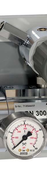
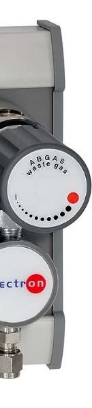
8 3. Description 3.1 Overview of the pressure control panel Drawing of the pressure control panel Elements of the pressure control panel Item. Designation Function Pressure regulator Pressure gauge Optional contact pressure gauge Pressure gauge Optional contact pressure gauge Waste gas valve or purge valve Optionally with pneumatic activation Connection block Relief valve Ambimat Back pressure return Reduces the variable inlet pressure to achieve a set outlet pressure level. Indicates the inlet pressure on the respective side. Display and electr. monitoring of the pressure Is opened gas pipe. Connecting point for the t pipe system. Protects the pressure control panel from impermissibly high outlet pressure. Does not function as a safety valve! Indicates the current outlet o pressure of the pressure regula- tor. Display and electr. monitoring of the pressure to remove the t waste gases or vent the process Fully automatic switching unit; gas supply is switched autoa spe- matically from the operating to the reserve side when cific pressure limit is reached. r change-over pressure is based on the inlet i and outlet pressure. Used to increase the change-over pressure. 8 GES_BM55-2A_1115.docx
9 3. Description Flow chart of gas supply with a pressure control panel GES_BM55-2A 1115.docx 9
10 3. Description 3.2 Functional description Pressure control panels in the BM555 2A series are double-.sided pressure control panels which reduce an inlet pressure which lies within a specific range to a required outlet pressure. pressure is reduced by the pressure regulator which is fitted behind thee Ambimat (change-over unit). In turn, the Ambimat switches from the side currently supplying the gas (operating side) to the reserve side when the so-called change- Initially, the side first pressurised is in operation. When the supply pressure sinkss towards the change-over pressure which is preset via the pressure control panel configuration,, the Ambimat switchess automatically from the operating to the reserve side. change-over process alsoo completelyy isolates the supply side which has just been taken out of operation from the gas supply. This means thatt a separatee process gas valve is not equired. over pressuree is reached. Selection of the operating side and change-over to the reserve side are a performed completely automatically. shut-off valve (cylinder valve) of the gas vessels (e.g. gas cylinders) which have been taken t out of opvia eration can now be closed and the pressure control panel side which is no longer in operation vented the waste gas valve. New gas cylinders shouldd be connected immediately and the shut-off valve opened so that they are ready for operation when the switching pressure is reached again. change-over pressure always depends on the pressure pending on the two sides of the panel. On the one hand, change-over only takes place when the pressure on the operating side drops to the t change-over pressure or below, while on the other hand, thee pressure on the reserve side must be at a certain minimum level that allows it to function as the actuating pressure for change-over to the reserve side. Under ideal conditions, the gas cylinders will bee full of gas at the pressure P1 listed on the type t plate of the change-over panel. If this is the case, change-over takes place at a pressure p slightly above the pressure P2 indicated on the type plate. If gas vessels with gas below the pressure P1 are connected to the panel, change-over takes place at a pressure below P2. Below a certain pressure limit,, the pressure on the re- serve side is no longer sufficient and change-over cannot take place. pressure control panels can be equipped with contact pressure gauges. se issue a change-over signal when a specific pressure limit is violated or, in the same way as pressuree transducers, supply a current that varies continuously with the pressure (4-20 ma). change-over signal or variable electrical current can bee processedd by means of connected control units, resulting, for example, in the issue of a gas shortage alarm. When these contact pressure gauges or pressure transducers are used in areas where theree is a risk of fire or explosion, special measures have to be taken, as described in directive 2014/34/EU (ATEX 95) and 1999/92/EEC (ATEX 137). Another option is to equip the pressure control panel with pneumaticalp lly operated valves. se require a pneumatic control pressuree of between a minimum of 6 bar and a maximum of 8 bar. 10 GES_BM55-2A_1115.docx
11 3. Description 3.33 Technical data technical data can be taken from the Spectron data sheet for the relevant product. If this is not available, you can view and download it at on.de. maximum inlet and outlet pressures and the gas type are a indicated on the type plate. 3.4 Connection options Inlet pressure connection: 1/4NPT femalee thread, usually equipped with a stainless steel compression fitting for 6mm pipes Outlet pressure connection: 1/4NPT femalee thread Relief valve: 1/4NPT femalee thread Extensionn connector: 1/4NPT femalee thread 4. Operation 4.1 Labelling Labelling example Hydrogen (H 2 2) BM55-2A M-M-H2 P1: 300 bar P2: 10 bar gas type must be specified on the pressuree control panel! If the gas type is not specified on the type plate, it must be done using the attached gas-typee adhesive labels before the device is put into operation for the first f time. Warning! Only the gas type for which the pressure control panel wass ordered may be specified on it. 4.2 Installing the pressure control panel You can find instructions on how to install the pressure control panel inn the installation manual MA_BM+BE. You can view and download this at GES_BM55-2A 1115.docx 11
12 4. Operation 4.3 Putting the pressure control panel intoo operation Important! Before putting the equipment into operation for the first time, the entire pressure control panel must be purged via the connection block right up to the consumer! It is imperative to adhere to the direction of the gas flow when doing this! You must not purge counter to the usual direction of flow (from the tapping point to the pressure control panel), since this can flush debris resulting from the instal- of lation work, for example, back into thee pressure regulator. connecting thread and connectingg surfaces of the gas cylinder c valves and the sealing rings the manual connectors of the pigtails must be checked to ensure they are in perfect condition. Pigtails with manual connectors are connected to gas cylinder valves without the need for tools. Pigtails with flat faces for tightening (generally for corrosive or o toxic gases) are tightened with a suitable spanner until they are gas-tight. In general but especially for filling the downstream installation the process gas valves must be opened gradually ensuring that any (audible) vibration of thee pressure regulator is avoided. Always turn shut-off valves as far as the stop when opening or closing them! Step 1 2 Activity Ensure that: gas type is specified on the pressure control panel All protective caps have been removed installation has been carried outt properly pigtails and other connecting points have been checked for leakss waste gas valves are closed (the red marking is visiblee in the handwheel window) pressure regulator is released. Pressure-purge the system: Slowly open the gas cylinder valves on the left and right. Slowly close the gas cylinder valves on the left and right. Open the waste gas valve on the leftt and right to relieve the pressure,, and then close it again. Repeat at least three times! If the inlet pressure is low, the process has to be repeated more often. 3 Slowly open the gas cylinder valve on the side which is to go into operation first Slowly open the gas cylinder valve on the reservee side. Set the pressuree regulator to t the desired outlet pressure by turning the handwheel clockwise. It is essential that no vibrations should be audible when filling thee downstream pipe, since otherwise the pressure regulator can be damaged. Check the entiree pressure control panel and all detachable connections for leakage. Gas can now be drawn. 12 GES_BM55-2A_1115.docx
13 4. Operation 4.44 Changing the cylinder Important! Step Once it is put into operation, both sides of the panel must always be connected - except when changing the gas cylinders. Each time you change the cylinder, check that the gasket is in perfect condition and replace it if necessary. Each time you change the cylinder, ambient air gets into the connectingg parts of the system. To prevent the gas and the entire system from being contaminated, the connection must be purged before gas is drawn from the cylinder again. In the case of non-toxic, non-corrosive gases, this can be done by means of multiple pressuree purges with own gas. Activity Close the gas cylinder valve of the emptied gas cylinder. To relieve the pressure completely, open the waste gas valve of the side on which the cylinder is to be changed. Close the waste gas valve again. Loosen the pigtail connection to thee gas cylinder valve, replace the gas cylinder, and connect the pigtail to the new gas cylinder inn accordance with the regulations. Check the cylinder connection and all of the connections you loosened for leakage again. Pressure-purgee the system: Slowly open the gas cylinder valve.. Close the gas cylinder valve. Open the waste gas valve of the side on whichh the cylinder has beenn changed this relieves the pressure. Close the waste gas valve again. Repeat at least three times! If the inlet pressure is low, the process has to be repeated more often. 4 Slowly open the gas cylinder valve. 5 Check the gas cylinder connection and all detachable connections for leakage. 4.5 Taking the equipment out off operationn Taking out of operation or interrupting operation for a short period When interrupting operation for a short period, all you need to do is close c the gas cylinder valve. GES_BM55-2A 1115.docx 13
14 4. Operation Taking out of operation or interrupting operation for a longer period Step Activity 1 Close all valves on the connected pressure cylinders. 2 Open the waste gas valves. 3 Any gas in the system flows out of thee waste gas pipe. 4 Close the waste gas valves. 5 pressure in the pressure control panel must be released by allowing the gas to t flow away via the consumer. It must be ensured that the indicators of the two t pressure gauges are on zero [0] visual check! 6 Relieve the pressure regulator 5. Problems Problem/cause Remedy Gas is released from the relief valve. Close all valves immediately. Impermissiblee increase in the outlet Have the pressure control panel inspected pressure. immediately by the manufacturer or an authorised specialist com- com- pany. pressuree regulator is making noises. Close all valves immediately. This indicates a defect. Have the pressure control panel inspected immediately by the manufacturer or an authorised specialist pany. pressuree regulator is frozen. Reduce the amount of gass drawn or This indicates that too much gas is being if technically, chemically, physically possible drawn. install an upstream gas preheater. re is a leak. Close all valves immediately. This indicates a defect in a pressure Have the pressure control panel inspected regulator component. immediately by the manufacturer or an authorised specialist com- the pany. outlet pressure level is unstable and Reduce the amount of gass drawn. is not adhering to the usual range of vargas pressure control panel must be checked by the manufactur er or It is also possible that there is dirt in the inlet filter. In this case, iation. This indicates that too much is being drawn. an authorised specialist company. Switchover from the operating to the re- at which does not have the required minimum pressure for switch- too low a pressure. over connected on the reserve side. re may be an empty pressure cylinder or a pressure cylinder serve side is not effected or is effected Connect a pressure cylinder with the pressure rating P1 indicated on the type label. 14 GES_BM55-2A_1115.docx
15 6. Maintenance, cleaning and repairs 6.1 Regular maintenance work and visual inspections Regular maintenance work To ensure the pressure control panel remains in perfect working order and a constantly highh level of opera- tional safety and reliability is maintained, the pressure control panel should s be checked once a year by a specialist. Regular visual inspections Visual inspection of all Interval parts for Damage Regular inspections at intervals of 12 months m and each time the t device is put Function into operation make an important contribution to the cost-effectiveness and Leaks preservation of the value of the fittings. Integrity/stability Corrosion If you find defects during the visual inspection, do not put the pressuree control panel into opera- tion! Have the pressure control panel inspected immediately by the manufacturerr or an author- ised specialist company. 6.2 Regular cleaning Warning! Detergents or disinfectants can corrode and ruin gaskets inside the fittings. Do not use deter- clean gents or disinfectants! If the equipment gets very dirty, this can interfere with operation. If it becomes necessary to the pressure control panel, use only a damp, lint-free cloth. Safe and reliable operation can only be guaranteed if original spare parts are used. 6.3 Repair information Important! Repairs may only be carried out by specialist personnel in authorised repair workshops. After re- inspection instructions. pairs, the entire pressure control panel must be checked inn accordance with the original Spectron manufacturer accepts no liabilityy for damage resulting from unauthorised repairs or modifica- tions carried out by the user or third parties without the express writtenn approval of the manufac- turer. 6.4 Returns If the pressuree control panel is returned to the manufacturer for testing, maintenance or repair, and it has been in contact with corrosive and toxic gases,, it is imperative that it is purged with inert gas. GES_BM55-2A 1115.docx 15
16 Spectron Gas Control Systems GmbH Fritz-Klatte-Straße 8 D Frankfurt Deutschland / Germany Phone: Fax: info@spectron.de Internet:
for the of and the EM55-1
 Operating Manua al for the Tapping Points of the EM55-1/EM55-2/EM55-3/ /EM55-4 series and the EE55-1/EE55-2/EE55-3/EE55-4 series EM55-1 Contents Contents... 2 1. Introduction... 3 1.1 General... 3 1.2
Operating Manual for the Cylinder and Line Pressure Regulators of the M51/M52/M53 series and E51/E52/E53 series
 Operating Manua al for the Cylinder and Line Pressuree Regulators of the M51/M52/M53 series and E51/E52/E53 series Contents Contents... 2 1. Introduction... 3 1.1 General... 3 1.2 Description of the cylinder
for Series FE51/52/53-SP
 Operating Manua al for cylinder pressure regulators with purge device Series FE5/52/53-SP Series FE2-SP Contents Contents... 2. Introduction... 3. General information... 3.2 Description of the Series FE5/52/53-SP
Instruction manual. for. purge and connection block SBE/3
 Instruction manual for purge and connection block SBE/3 Contents Contents... 2 1. Introduction... 3 1.1 General... 3 1.2 Description of the purge and connection blocks of series SBE/3... 3 1.3 Intended
Instruction manual. for. high purity gas pigtails 200 bar / 300 bar
 Instruction manual for high purity gas pigtails 200 bar / 300 bar Contents Contents... 2 1. Preface... 3 1.1 Overview... 3 1.2 General... 3 1.3 Intended use... 4 1.4 Personnel requirements... 4 2. For
Operating manual. for. tapping points of the EM15/EE15 series
 for tapping points of the Table of Contents Table of Contents... 2 1. Introduction... 3 1.1 General... 3 1.2 Description of the EM15 and EE15 tapping points series... 3 1.3 Intended use... 4 1.4 Personnel
Pressure Regulators. Operating Instructions. Instrumentation
 Pressure Regulators Operating Instructions FAILURE OR IMPROPER SELECTION OR IMPROPER USE OF THIS PRODUCT CAN CAUSE DEATH, PERSONAL INJURY AND PROPERTY DAMAGE. This document and other information from the
Measurement accessories METPOINT OCV for the measurement in systems up to 40 bar
 EN - english Instructions for installation and operation Measurement accessories METPOINT OCV for the measurement in systems up to 40 bar Dear customer, Thank you for deciding in favour of the METPOINT
THE BP-301 SERIES. Operating and Service Manual. Series includes all variants of BP-301 (LF 0.1Cv / MF 0.5Cv)
") THE BP-301 SERIES Operating and Service Manual Series includes all variants of BP-301 (LF 0.1Cv / MF 0.5Cv) Issue B October 2015 1 TABLE OF CONTENTS 1. Description... 3 2. Installation... 3 3. Operation...
THE BP-301 SERIES Operating and Service Manual Series includes all variants of BP-301 (LF 0.1Cv / MF 0.5Cv) Issue B October 2015 1 TABLE OF CONTENTS 1. Description... 3 2. Installation... 3 3. Operation...
Manual Actuated Boiler Blowdown Valves
 Manual Actuated Boiler Blowdown Valves Installation and Maintenance Instructions 1. Safety information 2. General product information 3. Installation 4. Operation 5. Maintenance 6. Spare parts p.1 1. Safety
TESCOM 50-4X Series Safety, Installation & Start-Up Procedures
 Operations & Service Manual TESCOM 50-4X Series Safety, Installation & Start-Up Procedures Do not attempt to select, install, use or maintain this product until you have read and fully understood this
PRESSURE REDUCING STATION INSTALLATION, OPERATIONS & MAINTENANCE MANUAL
 PRESSURE REDUCING STATION INSTALLATION, OPERATIONS & MAINTENANCE MANUAL Company Registered Office: Crown House, Stockport, Cheshire, SK13RB No. 850 0700 67 Registered in England and Wales No. 05058855
Inverted Bucket Steam Trap IB 16A-7
 Inverted Bucket Steam Trap IB 16A-7 Original Installation Instructions 819114-02 Contents Preface... 3 Availability... 3 Text layout... 3 Safety... 3 Usage for the intended purpose... 3 Basic safety notes...
Installation Operating Instructions for Simple Duplex Manual Manifolds PX-TSD Series
 Introduction Powerex manifolds are cleaned, tested and prepared for the indicated gas service and are built in accordance with the Compressed Gas Association guidelines. The manifold consists of a regulator
Operation Manual. Diaphragm Sensed Gas Pressure Regulators
 687 Technology Way Napa, CA 94558 Phone: (707) 259-0102 FAX: (707) 259-0117 www.aptech-online.com Diaphragm Sensed Gas (AP/AZ/AK Models: 20, 100, 500, 1000, 1000T 10PA, 1100, 1200, 12PA, 1300, 1400T, 14PA,
Installation Operating Instructions for Duplex Manual Manifolds PX-TMD Series
 Introduction Powerex manifolds are cleaned, tested and prepared for the indicated gas service and are built in accordance with the Compressed Gas Association guidelines. The manifold consists of a regulator
INSTRUCTIONS FOR MODELS SG3897 AND SG3898 CROSS PURGE ASSEMBLIES
 INSTRUCTIONS FOR MODELS SG3897 AND SG3898 CROSS PURGE ASSEMBLIES THIS BOOKLET CONTAINS PROPRIETARY INFORMATION OF ADVANCED SPECIALTY GAS EQUIPMENT CORP. AND IS PROVIDED TO THE PURCHASER SOLELY FOR USE
THE HF-300 SERIES. Operating and Service Manual. Series includes all variants of HF-300/301
 THE HF-300 SERIES Operating and Service Manual Series includes all variants of HF-300/301 Issue A July 2015 1 TABLE OF CONTENTS 1. Description... 3 2. Installation... 3 3. Operation... 4 3.1. Spring Loaded...
English. Introduction. Safety Instructions. All Products. Inspection and Maintenance Schedules. Parts Ordering. Specifications WARNING WARNING
 Contents All Products... Gb-1 Control Valves... Gb-2 Control Valve Actuators... Gb-3 Regulators... Gb-3 Relief Valves... Gb-4 Instruments, Switches, and Accessories... Gb-4 Products Covered by Battery
Mounting and Operating Instructions EB 2558 EN. Self-operated Pressure Regulators. Type Pressure Build-up Regulator
 Self-operated Pressure Regulators Type 2357-31 Pressure Build-up Regulator with safety function and integrated excess pressure valve Type 2357-31 with non-return unit at port C Ports A and B with soldering
Operating Manual. R280 Pressure regulator made of brass. 1. Intended Use
 Pressure regulator made of brass Operating Manual 1. Intended Use Line or outlet pressure regulators- /reducer for Air, gases and liquids which is designed to effect reduction to a downstream pressure
Type /2-Way Globe Valve 3/2-Wege-Geradsitzventil Vanne à siège droit 3/2 voies Operating Instructions Bedienungsanleitung Manuel d utilisation
 3/2-Way Globe Valve 3/2-Wege-Geradsitzventil Vanne à siège droit 3/2 voies Operating Instructions Bedienungsanleitung Manuel d utilisation We reserve the right to make technical changes without notice.
Protocol Switchover Station
 ADI 3215-B Certified ISO 9001 Protocol Switchover Station INSTALLATION AND OPERATION INSTRUCTIONS Before Installing or Operating, Read and Comply with These Instructions Controls Corporation of America
SINGLE STAGE ULTRA-HIGH PRESSURE REDUCING REGULATOR INSTALLATION AND OPERATION INSTRUCTIONS. Certified ISO 9001
 SINGLE STAGE ULTRA-HIGH PRESSURE REDUCING REGULATOR INSTALLATION AND OPERATION INSTRUCTIONS Before Installing or Operating, Read and Comply with These Instructions Warning: An appropriately sized pressure
VS18/26 with PROFINET and EtherNet/IP Interface. ATEX Installation Instructions
 VS18/26 with PROFINET and EtherNet/IP Interface ATEX Installation Instructions INDEX 1. INTENDED USAGE 3 2. OPERATING MANUAL ATEX 4 2.1 General conditions 4 2.2 Installation 5 2.3 Operating 5 2.4 Failures
Installation and operating manual. Pneumatic control station LK product no: PCS 1-10
 LK product no: PCS 1-10 Article no: 74503 Revision:8 Article no: 74503 Revision: 8 2 (23) Contents 1. General information... 5 2. Safety precautions... 5 2.1 Significance of symbols... 5 2.2 Explanatory
MST21 Stainless Steel Balanced Pressure Thermostatic Steam Trap
 1250650/6 IM-P125-07 ST Issue 6 MST21 Stainless Steel Balanced Pressure Thermostatic Steam Trap Installation and Maintenance Instructions 1. Safety information 2. General product information 3. Installation
Type 3709 Pneumatic Lock-up Valve. Translation of original instructions. Mounting and Operating Instructions EB 8391 EN
 Type 3709 Pneumatic Lock-up Valve Translation of original instructions Mounting and Operating Instructions EB 8391 EN Edition July 2017 Note on these mounting and operating instructions These mounting
Pressure Regulator. Instructions for Use
 Pressure Regulator Instructions for Use 702-0083.9 December 2017 1. Symbols Warning! Caution! Indicates a potentially hazardous situation which, if not avoided, could result in injury to the patient, the
Dri-Line Mk3 Monnier Compressed Air Drain Trap
 5044050/2 IM-P504-24 CH Issue 2 Dri-Line Mk3 Monnier Compressed Air Drain Trap Installation and Maintenance Instructions 1. Safety information 2. General product information 3. Installation and Operation
TA10A and TA10P Steam Tracing Temperature Control Valves Installation and Maintenance Instructions
 3500032/2 IM-P350-02 CH Issue 2 TA10A and TA10P Steam Tracing Temperature Control Valves Installation and Maintenance Instructions 1. Safety information 2. General product information 3. Installation 4.
Tri-Tech Medical Inc.
 Introduction Tri-Tech Medical manifolds are cleaned, tested and prepared for the indicated gas service and are built in accordance with the Compressed Gas Association guidelines. The manifold consists
This written Compressed Gas Plan is kept at the corporate office and in the written Safety & Health Program.
 Safety & Health Program 10627 Midwest Industrial Boulevard, St. Louis, MO Phone: 314-785-6425 Fax: 314-785-6426 Compressed Gas Plan Purpose It is the policy of EMA to permit only trained and authorized
MANUAL GAS MANIFOLDS
 MANUAL GAS MANIFOLDS Phoenix Pipeline Products Limited. Unit 8, McKenzie Industrial Park, Tel No.: 44 (0) 161 428 7200 Bird Hall Lane, Fax No.: 44 (0) 161 428 7010 Stockport, Email: info@p3-phoenix.com
Non-Return Valve SRK 22A
 Non-Return Valve SRK 22A Original Installation Instructions 819238-02 Contents Foreword... 3 Availability... 3 Formatting features in the document... 3 Safety... 3 Use for the intended purpose... 3 Basic
TSS21 Sealed Thermostatic Steam Tracer Trap
 1255050/4 IM-P125-10 ST Issue 4 TSS21 Sealed Thermostatic Steam Tracer Trap Installation and Maintenance Instructions 1. Safety information 2. General product information 3. Installation 4. Commissioning
CPX EMERGENCY STANDBY MANIFOLD INSTALLATION, OPERATIONS & MAINTENANCE MANUAL
 CPX EMERGENCY STANDBY MANIFOLD INSTALLATION, OPERATIONS & MAINTENANCE MANUAL Company Registered Office: Crown House, Stockport, Cheshire, SK13RB No. 850 0700 67 Registered in England and Wales No. 05058855
Operating and maintenance manual Filter and reducing station Series / 1.0
 Operating and maintenance manual Filter and reducing station Series 961 04.2017 / 1.0 Original instructions ARCA Regler GmbH. All rights reserved. Cover picture background: Freepik.com ARCA Regler GmbH
High Pressure Inlet Kits for CONCOA BlendMites and BlendMasters
 ADI 3210-A ADI 3210-A Certified ISO 9001 Certified ISO 9001 High Pressure Inlet Kits for CONCOA BlendMites and BlendMasters Warning: An appropriately sized pressure relief device downstream of the regulator
623 Series Dome Load Regulators
 ADI 3202C Certified ISO 9001 623 Series Dome Load Regulators INSTALLATION AND OPERATION INSTRUCTIONS This Equipment is intended to be installed and operated by trained personnel. Before Installing or Operating,
Spirax Compact FREME Flash Recovery Energy Management Equipment
 IM-UK-cFREME UK Issue 1 Spirax Compact FREME Flash Recovery Energy Management Equipment Installation and Maintenance Instructions 1. Safety information 2. General product information 3. Installation 4.
Eaton Filtration, LLC
 Eaton Filtration, LLC 900 Fairmount Avenue, Elizabeth, NJ 07207 Phone: 908-787-1000 Fax: 908-351-7893 E-Mail: filtration@eaton.com Web: www.filtration.eaton.com Installation, Operation & Service Manual
Operation Manual Piston Sensed Gas Pressure Regulators
 687 Technology Way Napa, CA 94558 Phone: (707) 259-0102 FAX: (707) 259-0117 www.aptech-online.com Operation Manual Piston Sensed Gas Pressure Regulators (Models KT9, KT10, Welded KT10, KT12) Table of Contents:
SAFETY PRINCIPLES FOR PRESSURE REGULATORS FOR MEDICAL OXYGEN CYLINDERS
 SAFETY PRINCIPLES FOR PRESSURE REGULATORS FOR MEDICAL OXYGEN CYLINDERS Doc 104/16 Revision of Doc 104/03 EUROPEAN INDUSTRIAL GASES ASSOCIATION AISBL AVENUE DES ARTS 3-5 B 1210 BRUSSELS Tel: +32 2 217 70
REDLINE pressure regulators for GENIE cylinders.
 Instruction manual Instructions. REDLINE pressure regulators for GENIE cylinders. 02 03 Operating instructions for cylinder pressure regulators. Linde reserves the right to change product specifications
SAFETY FEATURES OF PORTABLE CRYOGENIC LIQUID CONTAINERS FOR INDUSTRIAL AND MEDICAL GASES
 SAFETY FEATURES OF PORTABLE CRYOGENIC LIQUID CONTAINERS FOR INDUSTRIAL AND MEDICAL GASES AIGA 016/04 Asia Industrial Gases Association 298 Tiong Bahru Road, #20-01 Central Plaza, Singapore 168730 Tel :
Inert Air (N2) Systems Manual
 Systems Manual") INSTRUCTION MANUAL Inert Air (N2) Systems Manual N2-MANUAL 2.10 READ AND UNDERSTAND THIS MANUAL PRIOR TO OPERATING OR SERVICING THIS PRODUCT. GENERAL INFORMATION Positive pressure nitrogen gas pressurizing
INSTRUCTION MANUAL Inert Air (N2) Systems Manual N2-MANUAL 2.10 READ AND UNDERSTAND THIS MANUAL PRIOR TO OPERATING OR SERVICING THIS PRODUCT. GENERAL INFORMATION Positive pressure nitrogen gas pressurizing
Types 749B and R130 Changeover Manifolds
 Instruction Manual MCK-1179 Types 749B and R130 June 2012 Types 749B and R130 Changeover Manifolds TYPE HSRL-749B TYPE 64SR/122 TYPE R130/21 TYPE 749B/21 Figure 1. Changeover Manifolds and Regulator Assemblies
Type 2000 INOX. Quickstart. English Deutsch Français. 2/2-way angle seat valve 2/2-Wege Schrägsitzventil Vanne à siège incliné 2/2 voies
 Type 2000 INOX 2/2-way angle seat valve 2/2-Wege Schrägsitzventil Vanne à siège incliné 2/2 voies Quickstart English Deutsch Français Contents 1 QUICKSTART... 2 2 CONTACT ADDRESS... 2 3 INTENDED USE...
RS(H)10,15 USER MANUAL. Read the complete manual before installing and using the regulator.
10,15 USER MANUAL. Read the complete manual before installing and using the regulator.") RS(H)10,15 USER MANUAL Read the complete manual before installing and using the regulator. WARNING INCORRECT OR IMPROPER USE OF THIS PRODUCT CAN CAUSE SERIOUS PERSONAL INJURY AND PROPERTY DAMAGE. Due to
RS(H)10,15 USER MANUAL Read the complete manual before installing and using the regulator. WARNING INCORRECT OR IMPROPER USE OF THIS PRODUCT CAN CAUSE SERIOUS PERSONAL INJURY AND PROPERTY DAMAGE. Due to
THE BP-690 SERIES. Operating and Service Manual. Series includes all variants of BP-LF/MF-690/691
 THE BP-690 SERIES Operating and Service Manual Series includes all variants of BP-LF/MF-690/691 Issue B April 2015 1 TABLE OF CONTENTS 1. Description... 3 2. Installation... 3 3. Operation... 4 4. Special
Section 35 Brieser Construction SH&E Manual
 Brieser Construction SH&E Manual August 2017 Assure that employees handling compressed gases are adequately trained in the inherent hazards of the cylinders and their contents, as well as proper handling,
LRS(H)4 USER MANUAL. Read the complete manual before installing and using the regulator.
4 USER MANUAL. Read the complete manual before installing and using the regulator.") LRS(H)4 USER MANUAL Read the complete manual before installing and using the regulator. WARNING INCORRECT OR IMPROPER USE OF THIS PRODUCT CAN CAUSE SERIOUS PERSONAL INJURY AND PROPERTY DAMAGE. Due to the
LRS(H)4 USER MANUAL Read the complete manual before installing and using the regulator. WARNING INCORRECT OR IMPROPER USE OF THIS PRODUCT CAN CAUSE SERIOUS PERSONAL INJURY AND PROPERTY DAMAGE. Due to the
MEDICAL REGULATOR RANGE (MEDIREG RANGE)
") MEDICAL REGULATOR RANGE (MEDIREG RANGE) Medireg Dialreg Flowreg INSPECTION Remove the Medireg from the packaging and inspect for damage. If there is any damage, DO NOT USE, and contact Therapy Equipment
MEDICAL REGULATOR RANGE (MEDIREG RANGE) Medireg Dialreg Flowreg INSPECTION Remove the Medireg from the packaging and inspect for damage. If there is any damage, DO NOT USE, and contact Therapy Equipment
Type 0404 / /2-way solenoid valve 2/2-Wege-Magnetventil Électrovanne 2/2 voies Operating Instructions Bedienungsanleitung Manuel d utilisation
 Type 0404 / 5404 2/2-way solenoid valve 2/2-Wege-Magnetventil Électrovanne 2/2 voies Operating Instructions Bedienungsanleitung Manuel d utilisation 1 OPERATING INSTRUCTIONS The operating instructions
DF1 and DF2 Diffusers
 1550650/4 IM-P155-07 ST Issue 4 and Diffusers Installation and Maintenance Instructions 1. Safety information 2. General product information 3. Installation 4. Commissioning 5. Operation 6. Maintenance
Spiratec ST14, ST16 and ST17 Sensor Chambers and sensors
 0862050/1 IM-P086-18 MI Issue 1 Spiratec ST14, ST16 and ST17 Sensor Chambers and sensors Installation and Maintenance Instructions 1. Safety Information 2. General product information 3. Installation 4.
Bermad Pressure Reducing. Model: 42T
 Bermad Pressure Reducing Pilot Operated Pressure Control Valve Model: 42T Installation Operation Maintenance Manual (IOM) REV. 27.7.17 Page 1 of 12 Safety First BERMAD believes that the safety of personnel
Mounting and Operating Instructions EB 3007 EN. Self-operated Pressure Regulators. Differential Pressure Regulators (opening) Type Type 42-25
 Type Type 42-25") Self-operated Pressure Regulators Differential Pressure Regulators (opening) Type 42-20 Type 42-25 Type 42-20 Differential Pressure Regulator Type 42-25 Differential Pressure Regulator Mounting and Operating
Self-operated Pressure Regulators Differential Pressure Regulators (opening) Type 42-20 Type 42-25 Type 42-20 Differential Pressure Regulator Type 42-25 Differential Pressure Regulator Mounting and Operating
Safety Relief Valve HON 832
 Safety Relief Valve HON 832 product information serving the gas industry worldwide Application, characteristics, technical data Application 2 As leak gas SRV with internal vent connection (function class
FV Flash Vessel Installation and Maintenance Instructions
 4041050/5 IM-P404-10 EMM Issue 5 FV Flash Vessel Installation and Maintenance Instructions 1. Safety information 2. Specific product safety information 3. Product information 4. Installation 5. Commissioning
Incorrect installation, adjustment, or misuse of this burner could result severe personal injury, or substantial property damage.
 Operating instructions GB VD Burners Incorrect installation, adjustment, or misuse of this burner could result severe personal injury, or substantial property damage. To the Equipment Owner: Please read
Model: 720-UL INSTALLATION OPERATION MAINTENANCE. Bermad Pressure Reducing Valve IOM. Model: FP -720-UL Sizes: 2"-12" BERMAD. Application Engineering
 Bermad Pressure Reducing Valve Model: 720-UL INSTALLATION OPERATION MAINTENANCE Application Engineering BERMAD 1. Safety First BERMAD believes that the safety of personnel working with and around our equipment
SRV66 Sanitary Pressure Reducing Valve
 1866350/4 IM-P186-09 CH Issue 4 SRV66 Sanitary Pressure Reducing Valve Installation and Maintenance Instructions 1. Safety information 2. General product information 3. Installation 4. Operation 5. Commissioning
Pressure relief valve
 Pressure relief valve Operating manual Series DHV 718 Version BA-2016.01.11 EN Print-No. 300 524 TR MA DE Rev001 ASV Stübbe GmbH & Co. KG Hollwieser Straße 5 32602 Vlotho Germany Phone: +49 (0) 5733-799-0
453 Series Steam Heated Vaporizing Regulator
 ADI 0453A Certified ISO 9001:2000 453 Series Steam Heated Vaporizing Regulator INSTALLATION AND OPERATION INSTRUCTIONS Before Installing or Operating, Read and Comply with These Instructions Controls Corporation
PRS(TC)4,8 USER MANUAL. Read the complete manual before installing and using the regulator.
4,8 USER MANUAL. Read the complete manual before installing and using the regulator.") PRS(TC)4,8 USER MANUAL Read the complete manual before installing and using the regulator. WARNING INCORRECT OR IMPROPER USE OF THIS PRODUCT CAN CAUSE SERIOUS PERSONAL INJURY AND PROPERTY DAMAGE. Due to
PRS(TC)4,8 USER MANUAL Read the complete manual before installing and using the regulator. WARNING INCORRECT OR IMPROPER USE OF THIS PRODUCT CAN CAUSE SERIOUS PERSONAL INJURY AND PROPERTY DAMAGE. Due to
Declaration of Conformity as per Directive 97/23/EC
 Declaration of Conformity as per Directive 97/23/EC The manufacturer declares that:, 47906 Kempen, Germany Multi-way diverting valves Series 29a and Series 29b, with packing with lever 1. The valves are
624 Gas Panels INSTALLATION AND OPERATION INSTRUCTIONS. Before Installing or Operating, Read and Comply with These Instructions
 ADI 3203-A Certified ISO 9001 624 Gas Panels Warning: An appropriately sized pressure relief device downstream of the regulator should be installed in your system to prevent damage to equipment and/or
PV4 and PV6 Piston Valves
 1181250/1 IM-P118-05 ST Issue 1 PV4 and PV6 Piston Valves Installation and Maintenance Instructions 1. Safety information 2. General product information 3. Installation 4. Commissioning 5. Operation 6.
Float Operated Level Controllers
 CONTENTS Float Operated Level Controllers IM0015 Nov. 2014 PAGE Introduction 1 Scope 1 Description 1 Specification 1 Control Installation 2 INTRODUCTION Side Mount Back Mount Prior to installing, the instructions
Type Operating Instructions. 2/2-way solenoid valve 2/2-Wege Magnetventil Electrovanne 2/2 voies.
 2/2-way solenoid valve 2/2-Wege Magnetventil Electrovanne 2/2 voies We reserve the right to make technical changes without notice. Technische Änderungen vorbehalten. Sous réserve de modifications techniques.
KBV21i and KBV40i Key Operated Boiler Blowdown Valves Installation and Maintenance Instructions
 4059051/3 IM-P405-48 EMM Issue 3 KBV21i and KBV40i Key Operated Boiler Blowdown Valves Installation and Maintenance Instructions 1. Safety information 2. General product information 3. Installation 4.
THE MF-400 SERIES. Operating and Service Manual. Series includes all variants of MF-400/401
 THE MF-400 SERIES Operating and Service Manual Series includes all variants of MF-400/401 Issue A October 2013 1 TABLE OF CONTENTS 1. Description... 3 2. Installation... 3 3. Operation... 4 4. Special
CVS10 Sanitary Check Valves
 0299050/4 IM-P029-11 ST Issue 4 CVS10 Sanitary Check Valves Installation and Maintenance Instructions 1. Safety information CVS10 with soft seat 2. General product information 3. Operation 4. Installation
Oxygen Usage Best Practice Guide
 Oxygen Usage Best Practice Guide 1. Introduction Oxygen enriched systems possess a risk of fire and explosion since ignition and combustion hazards are present in all oxygen systems, and oxygen related
INSTALLATION INSTRUCTIONS. CVS 67CFR Pressure Reducing Instrument Supply Regulator INTRODUCTION
 INSTALLATION INSTRUCTIONS CVS 67CFR Pressure Reducing Instrument Supply Regulator INTRODUCTION The CVS Controls 67CFR Filter regulator is a pressure reducing supply regulator typically used for pneumatic
Tri-Safem Model I1 Regulator. INSTRUCTIONS and PARTS
 Tri-Safem Model I1 Regulator INSTRUCTIONS and PARTS USER RESPONSIBILITY This equipment will perform in conformity with the description thereof contained In this manual and accompanying labels andlor inserts
Flowmeter. Original operating manual DFM
 Flowmeter Original operating manual Series DFM 165 350 Version BA-2016.08.09 EN Print-No. 300 458 TR MA DE Rev002 ASV Stübbe GmbH & Co. KG Hollwieser Straße 5 32602 Vlotho Germany Phone: +49 (0) 5733-799-0
BOC: Living healthcare. Manual. LIV IQ BOC Integrated Valve with digital display portable delivery system for Medical Oxygen. BOC: Living healthcare
 BOC: Living healthcare Manual LIV IQ BOC Integrated Valve with digital display portable delivery system for Medical Oxygen. BOC: Living healthcare 02 Manual LIV IQ Oxygen Manual LIV IQ Oxygen 03 Contents.
TITAN FLOW CONTROL, INC.
 PREFACE: This manual contains information concerning the installation, operation, and maintenance of Titan Flow Control (Titan FCI) Simplex Basket Strainers. To ensure efficient and safe operation of Titan
MAINTENANCE & ASSEMBLY INSTRUCTIONS FUSIBLE LINK. Inline Thermal Check Valve
 MAINTENANCE & ASSEMBLY INSTRUCTIONS IOM-FL 12-16 ISO Registered Company FUSIBLE LINK Inline Thermal Check Valve MODEL FL-200 REFERENCE DATA: FL-200 Series Assembly Drawing No. A88-60200-00. INSTALLATION:
BT6HC Hygienic Sanitary Balanced Pressure Steam Trap for High Capacity and CIP/SIP Applications
 1800350/6 IM-P180-12 ST Issue 6 BT6HC Hygienic Sanitary Balanced Pressure Steam Trap for High Capacity and CIP/SIP Applications Installation and Maintenance Instructions 1. Safety information 2. General
CITY AND COUNTY OF DENVER CR&CF RISK UNIT Compressed Gas Safety Standard
 CITY AND COUNTY OF DENVER CR&CF RISK UNIT 65.5.11 Compressed Gas Safety Standard 1.0 Introduction 2.0 Scope This standard has been developed to protect all City and County of Denver employees and contractors
Pressure booster combination DPA-CRVZS. Operating instructions a [ ]
![Pressure booster combination DPA-CRVZS. Operating instructions a [ ]](/thumbs/88/116599651.jpg "Pressure booster combination DPA-CRVZS. Operating instructions a [ ]") Pressure booster combination en Operating instructions 8074546 2017-07a [8074548] Original instructions -EN Identification of hazards and instructions on how to prevent them: Danger Immediate dangers which
Pressure booster combination en Operating instructions 8074546 2017-07a [8074548] Original instructions -EN Identification of hazards and instructions on how to prevent them: Danger Immediate dangers which
Pressure relief valve
 Pressure relief valve Operating manual Series DHV 712 R Version BA-2016.01.19 EN Print-No. 300 472 TR MA DE Rev001 ASV Stübbe GmbH & Co. KG Hollwieser Straße 5 32602 Vlotho Germany Phone: +49 (0) 5733-799-0
CP10 Sensor Installation and Maintenance Instructions
 4030150/9 IM-P403-26 EMM Issue 9 CP10 Sensor Installation and Maintenance Instructions 1. Safety information 2. General product information 3. Installation 4. Maintenance 5. Spare parts Copyright 2017
Pressure maintenance valve SDV-P / SDV-P-E
 Translation of the original manual Pressure maintenance valve SDV-P / SDV-P-E Assembly and Operating Manual Superior Clamping and Gripping Imprint Imprint Copyright: This manual remains the copyrighted
CLEMENTS. ANA Oxygen Regulator with Yoke Connector. User Manual. Manual No. ANA Issue 1
 ANA 74300 Oxygen Regulator with Yoke Connector User Manual Manual No. ANA 74300 001 Issue 1 Safety Thank you for purchasing this Clements Oxygen Regulator. For your safety it is imperative that this unit
UIB30 and UIB30H Sealed Inverted Bucket Steam Traps for use with Pipeline Connectors
 1130050/4 IM-P113-02 ST Issue 4 UIB30 and UIB30H Sealed Inverted Bucket Steam Traps for use with Pipeline Connectors Installation and Maintenance Instructions 1. Safety information 2. General product information
Eaton Filtration, LLC
 Eaton Filtration, LLC 900 Fairmount Avenue, Elizabeth, NJ 07207 Phone: 908-787-1000 Fax: 908-351-7893 E-Mail: filtration@eaton.com Web: www.filtration.eaton.com Installation, Operation & Service Manual
MF2M Monnier Miniature Compressed Air Filter
 5040050 / 2 IM-P504-02 CH Issue 2 MF2M Monnier Miniature Compressed Air Filter Installation and Maintenance Instructions 1. Safety information 2. General product information 3. Installation and commissioning
APCO ARV CLEAN WATER AIR RELEASE VALVES. Model 50A
 APCO ARV CLEAN WATER AIR RELEASE VALVES Model 50A Instruction D12013 February 2017 Instructions These instructions provide installation, operation and maintenance information for APCO ARV Clean Water Air
SAFETY POLICY AND PROCEDURE MANUAL All Euramax Subsidiaries. Number K-3.0 Welding Safety Procedures
 Number K-3.0 Issued: 1/2009 Revised: 3/2016 Page 1 of 3 1.0 PURPOSE: To standardize procedures associated with production and maintenance welding and to minimize the potential risk of accident or injury
KTM 50 (DN ) Installation, maintenance and operating instructions
 Installation, maintenance and operating instructions") 52 762-306 09.2014 KTM 50 (DN 100-200) Installation, maintenance and operating instructions General High-performing and compact, these pressure-independent control valves for variable flow heating and
52 762-306 09.2014 KTM 50 (DN 100-200) Installation, maintenance and operating instructions General High-performing and compact, these pressure-independent control valves for variable flow heating and
CHAPTER 26 WELDING AND CUTTING
 CHAPTER 26 WELDING AND CUTTING Revised 7/2010 1 WELDING AND CUTTING Responsibilities 1. The County Safety Officer is responsible for providing appropriate safety instructions for supervisor's use on welding
Installation & Operation Manual Proven Quality since 1892
 Content 1. ERIKS operating companies 2. Product description 3. Requirements for maintenance staff 4. Transport and storage 5. Function 6. Application 7. Installation 8. Maintenance 9. Service and repair
SA121, SA122, SA123, SA128 and SA1219 Self-acting Temperature Control Systems (Knob Adjustment)
") 3810050/5 IM-P381-01 CH Issue 5 SA121, SA122, SA123, SA128 and SA1219 Self-acting Temperature Control Systems (Knob Adjustment) Installation and Maintenance Instructions 1. Safety information 2. Use 3.
3810050/5 IM-P381-01 CH Issue 5 SA121, SA122, SA123, SA128 and SA1219 Self-acting Temperature Control Systems (Knob Adjustment) Installation and Maintenance Instructions 1. Safety information 2. Use 3.
TECHNICAL DATA. Q = C v P S
 Page 1 of 13 1. DESCRIPTION The Viking 6 Model G-6000 Dry Valve Riser Assembly consists of a small profile, light weight, pilot operated valve that is used to separate the water supply from the dry sprinkler
Safety. Operating instructions Solenoid valve for gas VG 6 VG 15/10 DANGER. Contents WARNING CAUTION. Changes to edition 09.14
 15 Elster GmbH Edition 7.15 Translation from the German 519 D F NL I E DK S N P GR TR CZ PL RUS H www.docuthek.com Operating instructions Solenoid valve for gas VG VG 15/1 Contents Solenoid valve for gas