for Series FE51/52/53-SP
|
|
|
- Ella Cummings
- 6 years ago
- Views:
Transcription


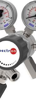


1 Operating Manua al for cylinder pressure regulators with purge device Series FE5/52/53-SP Series FE2-SP
2 Contents Contents Introduction General information Description of the Series FE5/52/53-SP and FE2-SP Intended use Personnel requirements For your safety Symbols used Essential safety information Safety devices Description Overview - structure Functional description Technical data Connection options Check valve in the purge gas inlet (9): Operation Labelling Installing the cylinder pressure regulator Putting the cylinder pressure regulator FE5/52/53-SP2A into operation Putting the cylinder pressure regulator FE5/52/53-SP2 and FE2-SP into operation Putting the cylinder pressure regulator FE5/52/53-SP3 into operation Changing the cylinder on cylinder pressure regulator FE5/52/53-SP2A Changing the cylinder on cylinder pressure regulator FE5/52/53-SP2 and FE2-SP Changing the cylinder on cylinder pressure regulator FE5/52/53-SP Taking out of operation Faults Maintenance, cleaning and repairs Regular maintenance work and visual inspections Regular cleaning Repair information Returns GES_FE SP+FE2SP_6.docx
3 . Introduction. General information Validity This Operating Manual applies to cylinder pressure regulators of Series FE5/52/53-SP and FE2-SP. Manufacturer Spectron Gas Control Systems GmbH Fritz-Klatte-Straße 8 D Frankfurt Deutschland / Germany Telephone: Fax: info@spectron.de Internet: Publication date October 206 Retention and completeness This Operating Manual is a component part of the cylinder pressure regulators of Series FE5/52/53-SP and FE2-SP and must be stored in a place where it is accessible to authorised persons at all times. Under no circumstances may chapters be removed from this Operating Manual. If the Operating Manual is lost or pages are missing in particular the chapter "For your safety," it/they must be replaced immediately. Copyright This Operating Manual contains information protected by copyright law. It must not be photocopied, reproduced, translated or copied onto data carriers, either in full or in part, without prior authorisation. All rights reserved. Updates No update service is provided for this Operating Manual by Spectron Gas Control Systems GmbH. Changes to this Operating Manual may be made without further notification..2 Description of the Series FE5/52/53-SP and FE2-SP Cylinder pressure regulators of the FE5/52/53-SP and FE2-SP Series are single-stage cylinder pressure regulators with pressure gauges for measurement of the inlet and outlet pressure. The main task of the cylinder pressure regulator is to reduce the inlet pressure to the outlet pressure required for the specific application. The letters "SP" denote cylinder pressure regulators equipped with a purge device The purge device is used, for example, in applications where penetration of atmospheric gas into the gaswetted area of the downstream pipe system up to the connected equipment is not desirable, requiring purging of the atmosphere before the pipe system is connected. The purge device is also used to flush toxic or corrosive process gas from the pressure regulator before it is removed from the gas cylinder, e.g. when changing the cylinder, preventing such gases in unpurged fittings reaching the surrounding atmosphere. GES_FE SP+FE2SP_6.docx 3
4 . Introduction.3 Intended use Intended use Cylinder pressure regulators of Series FE5/52/53-SP and FE2-SP are intended for use with corrosive gases up to quality 6.0. The permissible gases and pressure ranges are specified on the type plate. Cylinder pressure regulators reduce a variable inlet pressure to an outlet pressure which is as constant as possible. Introduction of pressure for the process gas is effected via the inlet screw fitting (e.g. cylinder connection). Appropriate measures must be taken to prevent the introduction of pressure via the pressure regulator outlet. Cylinder pressure regulators with the designation FE5/52/53-SP2A can be purged with the process gas via the two valves installed in the outlet. Cylinder pressure regulators with the designations FE5/52/53-SP2, FE5/52/53-SP3 and FE2-SP are equipped with an additional inlet valve, providing the option of purging the fitting with a separate purge gas. Pressure regulators without electrical components (such as a contact pressure gauge or pressure transducer) may be used in potentially explosive atmospheres, since they do not have a potential ignition source of their own (ignition hazard evaluated in accordance with DIN EN 3463-). The ignition hazard has to be taken into account with pressure regulators with electrical components. The ignition hazard must be evaluated based on the documentation for the respective electrical components, taking into account their incorporation into the overall system, and Directives 204/34/EU (ATEX 4) and 999/92/EC (ATEX 37) must be observed. Foreseeable misuse The following operating conditions are deemed to constitute misuse: Operation with gases that are not specified on the type plate Use with gases in their liquid state Operation outside the permissible technical limit values Non-observance of the legal regulations and other provisions valid on-site Failure to comply with this Operating Manual Failure to carry out inspection and maintenance work Failure to heed the information on the type plate and in the product data sheet Pressurisation counter to the normal direction of flow The mixing of gases via the normal gas inlet and the purge gas inlet 4 GES_FE SP+FE2SP_6.docx


5 . Introduction.4 Personnel requirements Definition of "authorised person" Authorised persons are persons with technical training, who have received technical instruction on the overall system and the associated hazards gas cylinder gas type gas cylinder valve pressure regulator and who have successfully completed training courses onn "The supply of pressurised gases." Tasks of the operating personnel Operating personnel must be able to recognisee and in as far as possible and permissible remedy faults and irregularities. Requirements for operating personnel In order to perform their tasks, operating personnel must meet the following requirements: The operating personnel must have received instruction in the operation of the pressuree regulator from an authorised person and must have read and understood this Operating Manual in its entirety. 2. For your safety 2. Symbols used Danger! This symbol warns that there is a "risk of fatal injury" or a health hazard for personnel Essential safety informationn Various laws, regulations, rules and directives apply when handling pressurised p gases and must be complied with, depending on the gas type. The following list lays no claim to be exhaustive; it merely represents a selectionn of important documents: EU Directive 2009/04/EC (Work Equipment Directive) Note! The following safety information is intended to supplement the applicable national accident prevention regulations and laws. Thee relevant accident prevention regulations and laws must always be complied with. EU Directive 999/92/EC (ATEX 37) EU Directive 98/24/EC (Dangerous Substances Directive) Industrial health and safety ordinance (implementationn of Directives 2009/04/EC in German law) Ordinance on hazardous substances (implementation of Directivee 98/24/EC and 999/92/EC in German law) TRBS (technical regulations on industrial safety and health) publications TRGS (German technical rules for f hazardous substances) publications GES_FE SP+FE2SP_6.docxx 5
6 2. For your safety TRAS (technical regulations on plant safety) publications BGV A German trade association basic accident prevention regulations BGR 04 German trade association rules on explosion protection BGR 32 German trade association rules for the avoidance of ignition hazards resulting from electrostatic charges BGR German trade association rules on welding, cutting and related work procedures BGR German trade association rules for working on gas lines BGR German trade association rules for the operation of oxygen systems BGR German trade association rules for the operation of systems that handle gas 2.3 Safety devices The pressure regulator is equipped with an integrated relief valve to protect the fitting. The versions with outlet pressures >00 bar do not have a relief valve. The user must ensure there is a suitable safety device installed downstream! Note! The relief valve allows gas that has to be released as a result of an impermissible rise in the outlet pressure to be blown off. It does not function as the safety valve for the entire gas supply system. Caution! In the event of failure of the pressure regulator and its relief valve, a safety mechanism that meets the requirements of the regulations for operators must be incorporated to protect downstream fittings, pressure vessels and pipes from excess pressure. Danger! With combustible, toxic, corrosive and other gases that are harmful to health or the environment, an exhaust pipe must be connected to the relief valve to discharge the gas safely. The factory setting of the relief valve must not be changed! Possible hazard Risk of fatal injury! As cylinder pressure regulators with a purge device are predominantly used with toxic and/or corrosive gases, it must be ensured that the purged gases are safely discharged and disposed of correctly. Risk of fatal injury! If oxygen comes into contact with oil or grease, there is a risk of fire due to a chemical reaction. Risk of fatal injury! Gas escaping into the ambient air can ignite; there is a risk of fire and explosion. Measures for prevention Connect a pipe routing the purged gases to a recycling facility to the waste gas valves of the cylinder pressure regulator. Keep all components which come into contact with oxygen completely free of oil and grease. Smoking and naked flames are strictly prohibited in the vicinity of gas supply systems 6 GES_FE SP+FE2SP_6.docx
7 2. For your safety Risk of fatal injury! The pressure regulator may be damaged by unauthorised changes or modifications and may no longer work as intended. There is a risk of the system malfunctioning, catching fire or being damaged. Risk of fatal injury! If gases other than those specified on the type plate are used, there is a risk of the system malfunctioning, catching fire or being damaged. Risk of fatal injury! Where the pressure regulator is operated with combustible, toxic or corrosive gases, the respective gas can escape into the environment if the relief valve is triggered. No changes or modifications may be made without the written approval of the manufacturer's authorised technical experts. Use only for the gases indicated on the device. If there are no gas types specified on the pressure regulator, the manufacturer must be consulted to establish which gases it can be used with. On no account may the pressure regulator be put into operation without this information. The relief valves of pressure regulators for combustible, toxic or corrosive gases must be equipped with a pipeline routing the escaping gases to a safe and legally compliant recycling facility. Risk of fatal injury! Gas escaping in an uncontrolled manner in closed rooms can reduce the oxygen content in the air to a potentially fatal level. The blow-off pipe of systems operated in closed rooms must be routed into the open air. Toxic, corrosive or otherwise environmentally harmful gases must be disposed of in accordance with the applicable regulations. Risk of fatal injury! Oxygen escaping in an uncontrolled manner in closed rooms can lead to a dangerous rise in the oxygen content in the air, increasing the risk of clothing and objects igniting. Risk of fatal injury! If components which are not suitable for the pressure range of the cylinder pressure regulator are connected, they may rupture under the pressure load. If the pressure regulator is used outside the specified ambient temperature range, there is a risk of the system malfunctioning, catching fire or being damaged. Dirt particles getting into the pressure regulator can damage it or cause it to malfunction. Incorrect handling and improper use may result in danger to the user and other persons and damage to the equipment. Route the blow-off pipe of oxygen systems operated in closed rooms into the open air, and avoid open flames. In addition, observe the instructions in EIGA document NL 79/04/D. All accessories to be connected (screw fittings, pipes, fittings etc.) must be suitable for the pressure range specified on the type plate of the cylinder pressure regulator. Do not use in ambient temperatures below 30 C or over +60 C. It must be ensured that no dirt particles of any kind can get into the pressure regulator. For this reason, there is a filter incorporated into the process gas inlet of the pressure control panel. Use and handle the pressure regulator only as described in this Operating Manual. If the connecting surfaces or gaskets of the fittings are damaged or missing, there is a danger of gas escaping in an uncontrolled manner. Check the connecting surfaces for damage, and do not install if the connecting surfaces are damaged or gaskets are missing. GES_FE SP+FE2SP_6.docx 7
8 3. Description 3. Overview - structure Cylinder pressure regulator FE5/52/53-SP2A (with valve combination for purging with process gas) PI 2Abgas PI 6 Verbraucher 4 8 Abgas Cylinder pressure regulator FE5/52/53-SP2 (with valve combination for purging with purge gas) PI 2Abgas PI 6 Verbraucher 9 4 Spülgas 8 GES_FE SP+FE2SP_6.docx
9 3. Description Cylinder pressure regulator FE5/52/53-SP3 (with valve combination for purging with purge gas) PI 2Abgas PI Verbraucher 4 8 Spülgas Abgas Cylinder pressure regulator FE2-SP (with valve combination for purging with purge gas) PI 2Abgas PI Verbraucher 6 Spülgas 9 Pos. Designation Description Gas cylinder valve In accordance with the applicable national standard 2 Cylinder connection In accordance with the applicable national standard 3 Inlet pressure gauge Indicates the current cylinder or inlet pressure. 4 Relief valve Protects the cylinder pressure regulator against excess pressure. 5 Outlet pressure gauge Indicates the current outlet pressure. 6 Handwheel Used to set the outlet pressure. 7 Process gas valve Used to close off the process gas pipe 8 Waste gas valve Used to close off the waste gas line 9 Purge gas valve Used to close off the purge gas line GES_FE SP+FE2SP_6.docx 9
10 3. Description 3.2 Functional description Cylinder pressure regulators of the FE5/52/53-SP and FE2-SP Series are single-stage cylinder pressure regulators with pressure gauges for measurement of the inlet and outlet pressure. The main task of the cylinder pressure regulator is to reduce the inlet pressure to the outlet pressure required for the specific application. The maximum inlet pressure depends on the specific application and will normally vary during operation. The outlet pressure should remain as constant as possible. The outlet pressure is set via the pressure regulator handwheel. The fittings described here are equipped with various valves depending on the variant (see diagrams in Section 3.) for purging of the cylinder pressure regulator itself or the connected pipe system. The purging process serves three essential purposes above all in the context of gas applications for sensitive processes and / or with toxic / corrosive gas applications:. In certain processes for which specific gas atmospheres are required, it is necessary to prevent the surrounding atmosphere penetrating into the pipe system connected downstream of the pressure regulator, as a disturbance in the process associated with the gas application would otherwise be caused. This is prevented by purging with process gas or purge gas. 2. Before opening a gas supply system operated with toxic or corrosive gases on the side of the surrounding atmosphere, it must be ensured that these gases cannot escape into the environment, as there is otherwise a risk of injury to personnel or damage to property. The purging process also prevents this undesirable outcome. 3. Purging fittings used with corrosive gases also extends the service life of the fittings. The correct procedure for carrying out the purging processes is described in detail for each type of cylinder pressure regulator in Sections 4.2 to Technical data Note! The technical data can be taken from the Spectron data sheet for the relevant product. If this is not available, you can view and download it at The maximum inlet and outlet pressures and the gas type are indicated on the type plate. 0 GES_FE SP+FE2SP_6.docx
11 3. Description 3.4 Connection options Inlet connection for process gas: Connection nozzle as per order specification and matching the gas cylinder valve Outlet, process gas valve (7): /4" NPT female thread Outlet, waste gas valve (8): /4" NPT female thread Outlet, relief valve (4): /4" NPT female thread Inlet connection, purge gas valve (9): /4" NPT female thread Screw fittings can now be screwed into the connection thread while applying opposing force to the valve, and the pipeline for process gas, waste gas and purge gas connected via these fittings. 3.5 Check valve in the purge gas inlet (9): To ensure that process gas cannot enter the purge gas line, we recommend the installation of a check valve (e.g. depending on the gas type, Spectron Part Nos or or ) in the inlet connection of the purge gas valve. The arrow indicating the flow direction points towards the purge gas valve. 4. Operation 4. Labelling Labelling example Gas type: NO FE5-SP DIN 8-NO P: 200 bar P2: 0 bar Note! Verification of successful leakage and functional testing is embossed on the reverse side of the cylinder pressure regulator. The labelling of the cylinder pressure regulator must indicate the gas type which is to be used! If the gas type is not specified on the type plate, the attached gas-type adhesive labels must be affixed before the device is put into operation for the first time. Warning! The cylinder pressure regulator may only be labelled with the gas type for which it was ordered. GES_FE SP+FE2SP_6.docx
12 4. Operation 4.2 Installing the cylinder pressure regulator Caution! It is imperativee to check that the connection threads and connecting surfaces of the gas cylinder valves and the gaskets are in perfectt condition. Step Activity Make sure that the cylinder pressure regulator is labelled for the correspondingg gas type and that the connectionn of the gas cylinder valve is cleann and showss no signs of damage. 2 Connect the cylinder pressure regulator to the still closed gas cylinder valve. To do this, use an open-end wrench of the same size as thee union nut on the cylinder connection (2). 3 Connect the following lines to the pressure regulator: processs gas pipe to the outlet thread of the process gas valve (7) waste gas line to the outlet thread of the relief valve (4) waste gas line to the outlet thread of the waste gas valve v (8) (only on FE5/52/53-SP2A and FE5/52/53-SP3) purge gas line to the inlet thread of the purge gas valve (9) ( only on FE5/52/53-SP2 and FE5/52/53-SP3 and FE2-SP) The NPT screw fittings to be inserted here must be wrappedd with PTFEE tape. The first thread must be left free of PTFE tape. 4 5 For oxygen or other gases with an oxidation potential greater g thann air, only use PTFE tape thatt has BAM approval. In the case of gases with combustible e, oxidising, toxic or corrosive characteristics, ensure safe discharge and subsequentt disposal of the waste gas in accordance with the relevant legislation. Then check all connections for leakage using suitable means. Warning! In the case of cylinder pressure regulators, it is not permissible to use adapters between the gas cylinder valve and the inlet of the cylinder pressure regulator. All connected accessories must be compatible with the gas type and suitable for the pressure range of thee cylinder pressure regulator model used. It is also imperative to ensure that the connection between the fitting and accessories is correct and in accordance with the forces and media used. If you are unsure about the suitabilityy of the accessories, you can contact our product consultants (see the back of this Operating Manual). 2 GES_FE SP+FE2SP_6.docx
13 4. Operation 4.3 Putting the cylinder pressure regulator FE5/52/53-SP2A into operation Step Activity Turn the handwheel (6) anti-clockwise to relieve the regulator spring of the cylinder pressure regulator and close all valves (7 and 8) attached to the cylinder pressure regulator by turning the handwheel clockwise. 2 Open the gas cylinder valve for the process gas () so that process gas can flow into the pressure regulator and set the desired outlet pressure for the pressure regulator via its handwheel (6). 3 Now slowly open the process gas valve (7), allowing the process gas to flow into the pipe system and to the connected equipment 4 Close the gas cylinder valve () and open the waste gas valve (8), routing the process gas to the recycling facility via the connected waste gas line. Close the waste gas valve (8) again immediately. 5 Close the process gas valve (7). 6 Repeat steps 7 to 0 (pressure purging with process gas) at least 5 times. 7 Open the gas cylinder valve () one final time. If necessary, correct the set outlet pressure at the pressure regulator again by turning the handwheel (6) and then slowly open the process gas valve (7) to allow the process gas to flow slowly into the downstream pipe system. The cylinder pressure regulator is now ready for operation. 4.4 Putting the cylinder pressure regulator FE5/52/53-SP2 and FE2-SP into operation Step Activity Turn the handwheel (6) anti-clockwise to relieve the regulator spring of the cylinder pressure regulator and close all valves (7 and 9) attached to the cylinder pressure regulator by turning the handwheel clockwise. Check that purge gas pressure is available, e.g. by opening the gas cylinder valve on the purge gas cylinder. 2 Slowly open the purge gas valve (9) so that purge gas flows into the cylinder pressure regulator, and set the desired outlet pressure for the pressure regulator via its handwheel (6). 3 Now slowly open the process gas valve (7), allowing the purge gas to flow into the pipe system and to the connected equipment (purging the line as far as the connected equipment). 4 Close the purge gas valve (9) and open a waste gas valve installed near the connected equipment to route the purge gas to the recycling facility via the connected waste gas line. Note: Depending on the structure of the gas supply system, purging can also be carried out through the connected equipment. In this case, the recommended duration of this type of purging depends on the individual parameters of the pipe system (pressure, length and diameter) and, of course, also on the experience of the plant personnel. GES_FE SP+FE2SP_6.docx 3
14 4. Operation 5 Close the process gas valve (7). 6 Repeat steps 3 to 5 (so-called pressure purging) at least 5 times. 7 Open the gas cylinder valve for the process gas (), allowing process gas to flow into the pressure regulator. 8 If necessary, correct the set outlet pressure at the pressure regulator by turning the handwheel (6) and then slowly open the process gas valve (7) to allow the process gas to flow slowly into the downstream pipe system. The cylinder pressure regulator is now ready for operation. 4.5 Putting the cylinder pressure regulator FE5/52/53-SP3 into operation Step Activity Turn the handwheel (6) anti-clockwise to relieve the regulator spring of the cylinder pressure regulator and close all valves (7, 8 and 9) attached to the cylinder pressure regulator by turning the handwheel clockwise. Check that purge gas pressure is available, e.g. by opening the gas cylinder valve on the purge gas cylinder. 2 Slowly open the purge gas valve (9) so that purge gas can flow into the cylinder pressure regulator, and set the desired outlet pressure for the cylinder pressure regulator via its handwheel (6). 3 Now slowly open the process gas valve (7), allowing the purge gas to flow into the pipe system and to the connected equipment (purging the line as far as the connected equipment). 4 Close the purge gas valve (9) and open the waste gas valve (8), routing the purge gas to the recycling facility via the connected waste gas line. Close the waste gas valve (8) again immediately. 5 Close the process gas valve (7). 6 Repeat steps 2 and 5 (pressure purging with purge gas) at least 5 times. 7 Open the gas cylinder valve for the process gas () so that process gas can flow into the pressure regulator. 8 Now slowly open the process gas valve (7), allowing the process gas to flow into the pipe system and to the connected equipment 9 Close the gas cylinder valve () and open the waste gas valve (8), routing the process gas to the recycling facility via the connected waste gas line. Close the waste gas valve (8) again immediately. 0 Close the process gas valve (7). Repeat steps 7 to 0 (pressure purging with process gas) at least 5 times. 2 Open the gas cylinder valve () one final time. If necessary, correct the set outlet pressure at the pressure regulator again by turning the handwheel (6) and then slowly open the process gas valve (7) to allow the process gas to flow slowly into the downstream pipe system. The cylinder pressure regulator is now ready for operation. 4 GES_FE SP+FE2SP_6.docx
15 4. Operation 4.6 Changing the cylinder on cylinder pressure regulator FE5/52/53-SP2A Step Caution! Each time you change the cylinder, check that the gasket is in perfect condition and replace it if necessary. Activity Close the process gas valve (7) of the cylinder pressure regulator and the gas cylinder valve () of the gas cylinder which is to be replaced. 2 Relieve the cylinder pressure regulator via the waste gas valve (8) and check that both pressure gauges show 0 bar. 3 Relieve the pressure regulator by turning the handwheel (6) anti-clockwise. 4 Disassemble the pressure regulator from the gas cylinder valve and connect the new gas cylinder. 5 Slowly open the gas cylinder valve () and set the desired outlet pressure for the cylinder pressure regulator via its handwheel (6). 6 Carry out pressure purging of the cylinder pressure regulator with process gas. To do this, close the gas cylinder valve (), open the waste gas valve (8) to drain the process gas from the cylinder pressure regulator and close the waste gas valve again immediately. 7 Repeat steps 7 to 0 (pressure purging with process gas) another 4 times. 8 Open the gas cylinder valve () one final time. If necessary, correct the set outlet pressure at the pressure regulator again by turning the handwheel (6) and then slowly open the process gas valve (7) to allow the process gas to flow slowly into the downstream pipe system. The cylinder pressure regulator is now ready for operation. 9 Check the gas cylinder connection (2) and all other detachable connections for leakage. 4.7 Changing the cylinder on cylinder pressure regulator FE5/52/53-SP2 and FE2-SP Step Caution! Each time you change the cylinder, check that the gasket is in perfect condition and replace it if necessary. Activity Close the gas cylinder valve () and the process gas valve (7) and slowly open the purge gas valve (9) to allow purge gas to flow into the pressure regulator. 2 Open the process gas valve (7) to drain the purge gas from the cylinder pressure regulator again. Close the process gas valve. 3 Open the purge gas valve (9) again to allow purge gas to flow into the pressure regulator. Then close the purge gas valve (9) again. 4 Open the process gas valve (7) to drain the purge gas from the cylinder pressure regulator again. Close the process gas valve (7). GES_FE SP+FE2SP_6.docx 5
16 4. Operation 5 Repeat steps 3 and 4 another 4 times. 6 Relieve the cylinder pressure regulator by turning the handwheel (6) anti-clockwise and check that both pressure gauges show 0 bar. 7 Disassemble the pressure regulator from the gas cylinder valve and connect the new gas cylinder. 8 Proceed as described in steps 2 to 6 of Section 4.4 to put the pressure regulator into operation again. 9 Check the gas cylinder connection (2) and all other detachable connections for leakage. 4.8 Changing the cylinder on cylinder pressure regulator FE5/52/53-SP3 Caution! Each time you change the cylinder, check that the gasket is in perfect condition and replace it if necessary. Step Activity Close the process gas valve (7) of the cylinder pressure regulator and the gas cylinder valve () of the gas cylinder which is to be replaced. 2 Relieve the cylinder pressure regulator via the waste gas valve (8) and close the valve again. 3 Open the purge gas valve (9) to allow purge gas to flow into the pressure regulator. Then close the purge gas valve (9) again. 4 Relieve the cylinder pressure regulator via the waste gas valve (8) and close the valve again. 5 Repeat steps 3 and 4 another 4 times. 6 Relieve the cylinder pressure regulator by turning the handwheel (6) anti-clockwise and check that both pressure gauges show 0 bar. 7 Disassemble the pressure regulator from the gas cylinder valve and connect the new gas cylinder. 8 Slowly open the purge gas valve (9) so that purge gas flows into the cylinder pressure regulator, and set the desired outlet pressure for the cylinder pressure regulator via its handwheel (6). Then close the purge gas valve (9) again. 9 Open the waste gas valve (8) to drain the purge gas from the cylinder pressure regulator again. Then close the waste gas valve (8) again. 0 Repeat steps 8 and 9 another 4 times. Slowly open the gas cylinder valve () and if necessary, correct the desired outlet pressure for the cylinder pressure regulator via its handwheel (6). Now close the gas cylinder valve () again. 2 Open the waste gas valve (8) to drain the process gas from the cylinder pressure regulator again. Then close the waste gas valve (8) again. 3 Repeat steps and 2 another 4 times. 4 Now slowly open the gas cylinder valve () again, then also slowly open the process gas valve, allowing the process gas to flow into the downstream pipe system, and check that all detachable connections are gastight. 6 GES_FE SP+FE2SP_6.docx
17 4. Operation 4.9 Taking out of operation Taking out of operation or interrupting operation for a short period If you are only interrupting work for a very brief period, it is sufficient to merely close the gas cylinder valve. Taking out of operation or interrupting operation for a longer period Carry out the steps described for your cylinder pressure regulator in the respective section "Changing the cylinder on cylinder pressure regulator FE SP." However, do not carry out the step in which the pressure regulator is released! To continue operation after an interruption, carry out the steps listed after the omitted step. 5. Faults Faults/cause Gas is blown off from the relief valve. Impermissible increase in the outlet pressure. The pressure regulator is making noises. This indicates a defect in the regulator insert. The pressure regulator is frozen. This indicates that too much gas is being withdrawn. There is a leak. This indicates a defect in a pressure regulator component. The outlet pressure level is unstable and is not adhering to the usual range of variation. This indicates that too much gas is being withdrawn. Remedy Close all valves immediately. Have the pressure regulator inspected immediately by the manufacturer or an authorised specialist company. Close all valves immediately. Have the pressure regulator inspected immediately by the manufacturer or an authorised specialist company. Reduce the amount of gas drawn or if technically, chemically, physically possible install an upstream gas preheater. Close all valves immediately. Have the pressure regulator inspected immediately by the manufacturer or an authorised specialist company. Reduce the amount of gas drawn. It is also possible that there is dirt in the inlet filter. In this case, the pressure regulator must be checked by the manufacturer or an authorised specialist company. GES_FE SP+FE2SP_6.docx 7
18 6. Maintenance, cleaning and repairs 6. Regular maintenance work and visual inspections Regular maintenance work To ensure problem-free and reliable operation, the pressure regulator should be inspected by an expert once a year. Regular visual inspections Visual inspection of all parts for Damage Correct functioning Leaks Integrity/stability Corrosion Interval Regular inspections at intervals of 2 months and each time the device is put into operation make an important contribution to the cost-effectiveness and preservation of the value of the fittings. Note! If you find defects during the visual inspection, do not put the pressure regulator into operation. Have the pressure regulator inspected immediately by the manufacturer or an authorised specialist company. 6.2 Regular cleaning Warning! Detergents or disinfectants can corrode and ruin gaskets inside the fittings. Do not use cleaning agents or disinfectants! Heavy soiling can lead to malfunctions. If it becomes necessary to clean the pressure regulator, use only a damp, lint-free cloth. 6.3 Repair information Caution! Repairs may only be carried out by specialist personnel in authorised repair workshops. After repairs, the entire pressure regulator must be checked in accordance with the original Spectron inspection instructions. Safe and reliable operation can only be guaranteed if original spare parts are used. Note! The manufacturer accepts no liability for damage resulting from unauthorised repairs or modifications carried out by the user or third parties without the express written approval of the manufacturer. 6.4 Returns If the pressure regulator is returned to the manufacturer for testing, maintenance or repair, and it has been in contact with corrosive or toxic gases, it is imperative that it is purged with inert gas. 8 GES_FE SP+FE2SP_6.docx
19 Spectron Gas Control Systems GmbH Fritz-Klatte-Straße Frankfurt Deutschland / Germany Telephone: Fax: info@spectron.de Internet:
for the of and the EM55-1
 Operating Manua al for the Tapping Points of the EM55-1/EM55-2/EM55-3/ /EM55-4 series and the EE55-1/EE55-2/EE55-3/EE55-4 series EM55-1 Contents Contents... 2 1. Introduction... 3 1.1 General... 3 1.2
Operating Manual for the Cylinder and Line Pressure Regulators of the M51/M52/M53 series and E51/E52/E53 series
 Operating Manua al for the Cylinder and Line Pressuree Regulators of the M51/M52/M53 series and E51/E52/E53 series Contents Contents... 2 1. Introduction... 3 1.1 General... 3 1.2 Description of the cylinder
Instruction manual. for. high purity gas pigtails 200 bar / 300 bar
 Instruction manual for high purity gas pigtails 200 bar / 300 bar Contents Contents... 2 1. Preface... 3 1.1 Overview... 3 1.2 General... 3 1.3 Intended use... 4 1.4 Personnel requirements... 4 2. For
Instruction manual. for. purge and connection block SBE/3
 Instruction manual for purge and connection block SBE/3 Contents Contents... 2 1. Introduction... 3 1.1 General... 3 1.2 Description of the purge and connection blocks of series SBE/3... 3 1.3 Intended
Operating manual. for. tapping points of the EM15/EE15 series
 for tapping points of the Table of Contents Table of Contents... 2 1. Introduction... 3 1.1 General... 3 1.2 Description of the EM15 and EE15 tapping points series... 3 1.3 Intended use... 4 1.4 Personnel
Instruction manual for the pressure control panels of the BM55-2A series
 Instruction manual for the pressuree control panels of the BM55-2A series BM55-2A Contents Contents... 2 1. Introduction... 3 1.1 General... 3 1.2 Description of the pressure control panels of the BM series...
Measurement accessories METPOINT OCV for the measurement in systems up to 40 bar
 EN - english Instructions for installation and operation Measurement accessories METPOINT OCV for the measurement in systems up to 40 bar Dear customer, Thank you for deciding in favour of the METPOINT
THE BP-301 SERIES. Operating and Service Manual. Series includes all variants of BP-301 (LF 0.1Cv / MF 0.5Cv)
") THE BP-301 SERIES Operating and Service Manual Series includes all variants of BP-301 (LF 0.1Cv / MF 0.5Cv) Issue B October 2015 1 TABLE OF CONTENTS 1. Description... 3 2. Installation... 3 3. Operation...
THE BP-301 SERIES Operating and Service Manual Series includes all variants of BP-301 (LF 0.1Cv / MF 0.5Cv) Issue B October 2015 1 TABLE OF CONTENTS 1. Description... 3 2. Installation... 3 3. Operation...
453 Series Steam Heated Vaporizing Regulator
 ADI 0453A Certified ISO 9001:2000 453 Series Steam Heated Vaporizing Regulator INSTALLATION AND OPERATION INSTRUCTIONS Before Installing or Operating, Read and Comply with These Instructions Controls Corporation
SAFETY FEATURES OF PORTABLE CRYOGENIC LIQUID CONTAINERS FOR INDUSTRIAL AND MEDICAL GASES
 SAFETY FEATURES OF PORTABLE CRYOGENIC LIQUID CONTAINERS FOR INDUSTRIAL AND MEDICAL GASES AIGA 016/04 Asia Industrial Gases Association 298 Tiong Bahru Road, #20-01 Central Plaza, Singapore 168730 Tel :
Mounting and Operating Instructions EB 2558 EN. Self-operated Pressure Regulators. Type Pressure Build-up Regulator
 Self-operated Pressure Regulators Type 2357-31 Pressure Build-up Regulator with safety function and integrated excess pressure valve Type 2357-31 with non-return unit at port C Ports A and B with soldering
Operating Manual. R280 Pressure regulator made of brass. 1. Intended Use
 Pressure regulator made of brass Operating Manual 1. Intended Use Line or outlet pressure regulators- /reducer for Air, gases and liquids which is designed to effect reduction to a downstream pressure
CARTRIDGE FILTERS TECHNICAL MANUAL MT 080. Installation, commissioning and maintenance instructions. 08/02 Edition
 CARTRIDGE FILTERS TECHNICAL MANUAL MT 080 Installation, commissioning and maintenance instructions 08/02 Edition 1 2 CONTENTS 1.0 PAGE INTRODUCTION 1.1 MAIN FEATURES 1.2 OPERATION 1.3 CLOSING OF HEAD WITH
SAFETY PRINCIPLES FOR PRESSURE REGULATORS FOR MEDICAL OXYGEN CYLINDERS
 SAFETY PRINCIPLES FOR PRESSURE REGULATORS FOR MEDICAL OXYGEN CYLINDERS Doc 104/16 Revision of Doc 104/03 EUROPEAN INDUSTRIAL GASES ASSOCIATION AISBL AVENUE DES ARTS 3-5 B 1210 BRUSSELS Tel: +32 2 217 70
Tri-Safem Model I1 Regulator. INSTRUCTIONS and PARTS
 Tri-Safem Model I1 Regulator INSTRUCTIONS and PARTS USER RESPONSIBILITY This equipment will perform in conformity with the description thereof contained In this manual and accompanying labels andlor inserts
Mounting and Operating Instructions EB 3007 EN. Self-operated Pressure Regulators. Differential Pressure Regulators (opening) Type Type 42-25
 Type Type 42-25") Self-operated Pressure Regulators Differential Pressure Regulators (opening) Type 42-20 Type 42-25 Type 42-20 Differential Pressure Regulator Type 42-25 Differential Pressure Regulator Mounting and Operating
Self-operated Pressure Regulators Differential Pressure Regulators (opening) Type 42-20 Type 42-25 Type 42-20 Differential Pressure Regulator Type 42-25 Differential Pressure Regulator Mounting and Operating
REDLINE pressure regulators for GENIE cylinders.
 Instruction manual Instructions. REDLINE pressure regulators for GENIE cylinders. 02 03 Operating instructions for cylinder pressure regulators. Linde reserves the right to change product specifications
High Pressure Inlet Kits for CONCOA BlendMites and BlendMasters
 ADI 3210-A ADI 3210-A Certified ISO 9001 Certified ISO 9001 High Pressure Inlet Kits for CONCOA BlendMites and BlendMasters Warning: An appropriately sized pressure relief device downstream of the regulator
THE HF-300 SERIES. Operating and Service Manual. Series includes all variants of HF-300/301
 THE HF-300 SERIES Operating and Service Manual Series includes all variants of HF-300/301 Issue A July 2015 1 TABLE OF CONTENTS 1. Description... 3 2. Installation... 3 3. Operation... 4 3.1. Spring Loaded...
Pressure Regulators. Operating Instructions. Instrumentation
 Pressure Regulators Operating Instructions FAILURE OR IMPROPER SELECTION OR IMPROPER USE OF THIS PRODUCT CAN CAUSE DEATH, PERSONAL INJURY AND PROPERTY DAMAGE. This document and other information from the
Operating Instructions in compliance with Pressure Equipment Directive 2014/68/EU. FAS Manual Brass Shut-Off Valve DN10 through DN22
 Operating Instructions in compliance with Pressure Equipment Directive 2014/68/EU FAS Manual Brass Shut-Off Valve DN10 through DN22 Please read these operating instructions carefully to ensure a safe operation
TESCOM 50-4X Series Safety, Installation & Start-Up Procedures
 Operations & Service Manual TESCOM 50-4X Series Safety, Installation & Start-Up Procedures Do not attempt to select, install, use or maintain this product until you have read and fully understood this
VS18/26 with PROFINET and EtherNet/IP Interface. ATEX Installation Instructions
 VS18/26 with PROFINET and EtherNet/IP Interface ATEX Installation Instructions INDEX 1. INTENDED USAGE 3 2. OPERATING MANUAL ATEX 4 2.1 General conditions 4 2.2 Installation 5 2.3 Operating 5 2.4 Failures
Type 0404 / /2-way solenoid valve 2/2-Wege-Magnetventil Électrovanne 2/2 voies Operating Instructions Bedienungsanleitung Manuel d utilisation
 Type 0404 / 5404 2/2-way solenoid valve 2/2-Wege-Magnetventil Électrovanne 2/2 voies Operating Instructions Bedienungsanleitung Manuel d utilisation 1 OPERATING INSTRUCTIONS The operating instructions
Inverted Bucket Steam Trap IB 16A-7
 Inverted Bucket Steam Trap IB 16A-7 Original Installation Instructions 819114-02 Contents Preface... 3 Availability... 3 Text layout... 3 Safety... 3 Usage for the intended purpose... 3 Basic safety notes...
Type 2000 INOX. Quickstart. English Deutsch Français. 2/2-way angle seat valve 2/2-Wege Schrägsitzventil Vanne à siège incliné 2/2 voies
 Type 2000 INOX 2/2-way angle seat valve 2/2-Wege Schrägsitzventil Vanne à siège incliné 2/2 voies Quickstart English Deutsch Français Contents 1 QUICKSTART... 2 2 CONTACT ADDRESS... 2 3 INTENDED USE...
Type Operating Instructions. 2/2-way solenoid valve 2/2-Wege Magnetventil Electrovanne 2/2 voies.
 2/2-way solenoid valve 2/2-Wege Magnetventil Electrovanne 2/2 voies We reserve the right to make technical changes without notice. Technische Änderungen vorbehalten. Sous réserve de modifications techniques.
Type /2-Way Globe Valve 3/2-Wege-Geradsitzventil Vanne à siège droit 3/2 voies Operating Instructions Bedienungsanleitung Manuel d utilisation
 3/2-Way Globe Valve 3/2-Wege-Geradsitzventil Vanne à siège droit 3/2 voies Operating Instructions Bedienungsanleitung Manuel d utilisation We reserve the right to make technical changes without notice.
Operating and maintenance manual Filter and reducing station Series / 1.0
 Operating and maintenance manual Filter and reducing station Series 961 04.2017 / 1.0 Original instructions ARCA Regler GmbH. All rights reserved. Cover picture background: Freepik.com ARCA Regler GmbH
623 Series Dome Load Regulators
 ADI 3202C Certified ISO 9001 623 Series Dome Load Regulators INSTALLATION AND OPERATION INSTRUCTIONS This Equipment is intended to be installed and operated by trained personnel. Before Installing or Operating,
Pressure relief valve
 Pressure relief valve Operating manual Series DHV 718 Version BA-2016.01.11 EN Print-No. 300 524 TR MA DE Rev001 ASV Stübbe GmbH & Co. KG Hollwieser Straße 5 32602 Vlotho Germany Phone: +49 (0) 5733-799-0
Declaration of Conformity as per Directive 97/23/EC
 Declaration of Conformity as per Directive 97/23/EC The manufacturer declares that:, 47906 Kempen, Germany Multi-way diverting valves Series 29a and Series 29b, with packing with lever 1. The valves are
Non-Return Valve SRK 22A
 Non-Return Valve SRK 22A Original Installation Instructions 819238-02 Contents Foreword... 3 Availability... 3 Formatting features in the document... 3 Safety... 3 Use for the intended purpose... 3 Basic
THE BP-690 SERIES. Operating and Service Manual. Series includes all variants of BP-LF/MF-690/691
 THE BP-690 SERIES Operating and Service Manual Series includes all variants of BP-LF/MF-690/691 Issue B April 2015 1 TABLE OF CONTENTS 1. Description... 3 2. Installation... 3 3. Operation... 4 4. Special
User manual. ZX trolley.
 User manual. ZX trolley. Date July 2011 02 User manual. ZX trolley. ZX trolley. Safe transportation for medical gas cylinders. Important Please read this manual carefully before attempting to use the BOC
PRESSURE REDUCING STATION INSTALLATION, OPERATIONS & MAINTENANCE MANUAL
 PRESSURE REDUCING STATION INSTALLATION, OPERATIONS & MAINTENANCE MANUAL Company Registered Office: Crown House, Stockport, Cheshire, SK13RB No. 850 0700 67 Registered in England and Wales No. 05058855
DK46 - DK800 Supplementary instructions
 DK46 - DK800 Supplementary instructions Variable area flowmeter Device category II2G with electrical internals Additional Ex manual KROHNE CONTENTS DK46 - DK800 1 Safety instructions 3 1.1 General... 3
English. Introduction. Safety Instructions. All Products. Inspection and Maintenance Schedules. Parts Ordering. Specifications WARNING WARNING
 Contents All Products... Gb-1 Control Valves... Gb-2 Control Valve Actuators... Gb-3 Regulators... Gb-3 Relief Valves... Gb-4 Instruments, Switches, and Accessories... Gb-4 Products Covered by Battery
SINGLE STAGE ULTRA-HIGH PRESSURE REDUCING REGULATOR INSTALLATION AND OPERATION INSTRUCTIONS. Certified ISO 9001
 SINGLE STAGE ULTRA-HIGH PRESSURE REDUCING REGULATOR INSTALLATION AND OPERATION INSTRUCTIONS Before Installing or Operating, Read and Comply with These Instructions Warning: An appropriately sized pressure
DIAPHRAGM PRESSURE CONTROL VALVE FDV 30 / 31, FDV 1.30 / 1.30 FDV 300 / 301, FDV / 1.301
 DIAPHRAGM PRESSURE CONTROL VALVE FDV 30 / 31, FDV 1.30 / 1.30 FDV 300 / 301, FDV 1.300 / 1.301 FDV 31 KP Z A: Pump Accessories KP/KP.51 / KV / KT / TV / TT 30 / 1.30 / 31 / 1.31 / 300 / 1.300 / 301 / 1.301
Mounting and Operating Instructions EB 3017 EN. Self-operated Regulators
 Self-operated Regulars Flow and Differential Pressure Regular Type 42-37 Flow and Differential Pressure or Flow and Pressure Regular Type 42-39 Type 42-37 Type 42-39 Fig. 1 Flow and differential pressure
CPX EMERGENCY STANDBY MANIFOLD INSTALLATION, OPERATIONS & MAINTENANCE MANUAL
 CPX EMERGENCY STANDBY MANIFOLD INSTALLATION, OPERATIONS & MAINTENANCE MANUAL Company Registered Office: Crown House, Stockport, Cheshire, SK13RB No. 850 0700 67 Registered in England and Wales No. 05058855
Working Environment Safety Assessment
 For your own safety and/or safety of your workforce, and to improve the efficiency of your business practices, you should be aware of, and be up to date with, the key safety issues and good practices relevant
MAINTENANCE AND OPERATING MANUAL
 MAINTENANCE AND OPERATING MANUAL Cyclone condensate separator Type ASA EN EN Maintenance and operating manual Purpose and appropriate use Dear Customer, thank you for choosing our product. In order to
CLEMENTS. ANA Oxygen Regulator with Yoke Connector. User Manual. Manual No. ANA Issue 1
 ANA 74300 Oxygen Regulator with Yoke Connector User Manual Manual No. ANA 74300 001 Issue 1 Safety Thank you for purchasing this Clements Oxygen Regulator. For your safety it is imperative that this unit
MEDICAL REGULATOR RANGE (MEDIREG RANGE)
") MEDICAL REGULATOR RANGE (MEDIREG RANGE) Medireg Dialreg Flowreg INSPECTION Remove the Medireg from the packaging and inspect for damage. If there is any damage, DO NOT USE, and contact Therapy Equipment
MEDICAL REGULATOR RANGE (MEDIREG RANGE) Medireg Dialreg Flowreg INSPECTION Remove the Medireg from the packaging and inspect for damage. If there is any damage, DO NOT USE, and contact Therapy Equipment
THE MF-400 SERIES. Operating and Service Manual. Series includes all variants of MF-400/401
 THE MF-400 SERIES Operating and Service Manual Series includes all variants of MF-400/401 Issue A October 2013 1 TABLE OF CONTENTS 1. Description... 3 2. Installation... 3 3. Operation... 4 4. Special
3G Operating instructions. Digital Purge Gas Valve 3G Type: Document no.: D0001 Version: 01. July 2011/Rev.
 3G Operating instructions Type: 03-5110-00.. Document no.: 03-5110-7D0001 Version: 01. July 2011/Rev. 0 Operating Instructions Type: 03-5110-00.. Document no.: 03-5110-7D0001 Version: 1 July 2011 / Rev.
Differential Pressure Regulator Type Type 45-6 (0.1 to 1 bar, DN 15) Mounting and Operating Instructions EB 3226 EN
 Mounting and Operating Instructions EB 3226 EN") Differential Pressure Regulator Type 45-6 Type 45-6 (0.1 to 1 bar, DN 15) Mounting and Operating Instructions EB 3226 EN Edition March 2008 Contents Contents Page 1 Design and principle of operation...................
Differential Pressure Regulator Type 45-6 Type 45-6 (0.1 to 1 bar, DN 15) Mounting and Operating Instructions EB 3226 EN Edition March 2008 Contents Contents Page 1 Design and principle of operation...................
Mounting and operating instructions EB 2530 EN. Self-operated Pressure Regulator. Pressure Reducing Valve Type M 44-2
 Self-operated Pressure Regulator Pressure Reducing Valve Type M 44-2 Type M 44-2, connection G 1 4, K VS = 0.15 Type M 44-2, connection G 1, K VS = 6 Fig. 1 Type M 44-2 Pressure Reducing Valve Mounting
COSASCO 3600 PSI SINGLE ISOLATION SERVICE VALVE (FR) MAINTENANCE
 MAINTENANCE") COSASCO 3600 PSI SINGLE ISOLATION SERVICE VALVE (FR) MAINTENANCE Rohrback Cosasco Systems, Inc. 11841 E. Smith Avenue Santa Fe Springs, CA 90670 Tel: (562) 949-0123 (800) 635-6898 Fax: (562) 949-3065 www.cosasco.com
COSASCO 3600 PSI SINGLE ISOLATION SERVICE VALVE (FR) MAINTENANCE Rohrback Cosasco Systems, Inc. 11841 E. Smith Avenue Santa Fe Springs, CA 90670 Tel: (562) 949-0123 (800) 635-6898 Fax: (562) 949-3065 www.cosasco.com
KBV21i and KBV40i Key Operated Boiler Blowdown Valves Installation and Maintenance Instructions
 4059051/3 IM-P405-48 EMM Issue 3 KBV21i and KBV40i Key Operated Boiler Blowdown Valves Installation and Maintenance Instructions 1. Safety information 2. General product information 3. Installation 4.
Pressure Regulator. Instructions for Use
 Pressure Regulator Instructions for Use 702-0083.9 December 2017 1. Symbols Warning! Caution! Indicates a potentially hazardous situation which, if not avoided, could result in injury to the patient, the
LRS(H)4 USER MANUAL. Read the complete manual before installing and using the regulator.
4 USER MANUAL. Read the complete manual before installing and using the regulator.") LRS(H)4 USER MANUAL Read the complete manual before installing and using the regulator. WARNING INCORRECT OR IMPROPER USE OF THIS PRODUCT CAN CAUSE SERIOUS PERSONAL INJURY AND PROPERTY DAMAGE. Due to the
LRS(H)4 USER MANUAL Read the complete manual before installing and using the regulator. WARNING INCORRECT OR IMPROPER USE OF THIS PRODUCT CAN CAUSE SERIOUS PERSONAL INJURY AND PROPERTY DAMAGE. Due to the
Operating Instructions in compliance with Pressure Equipment Directive 2014/68/EU. AWA Change-over Valve
 Operating Instructions in compliance with Pressure Equipment Directive 2014/68/EU AWA Change-over Valve Please read these operating instructions carefully to ensure a safe operation and keep the same for
PRAHER PLC-MP AQUASTAR MANAUL 2009
 PRAHER PLC-MP AQUASTAR MANAUL 2009 1. Copyrights This Operating Manual contains copyright-protected information. All rights reserved to Praher Kunststofftechnik GmbH. This Operating Manual is designed
CITY AND COUNTY OF DENVER CR&CF RISK UNIT Compressed Gas Safety Standard
 CITY AND COUNTY OF DENVER CR&CF RISK UNIT 65.5.11 Compressed Gas Safety Standard 1.0 Introduction 2.0 Scope This standard has been developed to protect all City and County of Denver employees and contractors
Operating Instructions in accordance with the Machines Directive 2006/42/EC
 Lubricating Equipment Metering Technology for Grease and Oil High Pressure Hydraulic Customised Developments Operating Instructions in accordance with the Machines Directive 2006/42/EC Compressed air filling
FV Flash Vessel Installation and Maintenance Instructions
 4041050/5 IM-P404-10 EMM Issue 5 FV Flash Vessel Installation and Maintenance Instructions 1. Safety information 2. Specific product safety information 3. Product information 4. Installation 5. Commissioning
INSTRUCTIONS FOR MODELS SG3897 AND SG3898 CROSS PURGE ASSEMBLIES
 INSTRUCTIONS FOR MODELS SG3897 AND SG3898 CROSS PURGE ASSEMBLIES THIS BOOKLET CONTAINS PROPRIETARY INFORMATION OF ADVANCED SPECIALTY GAS EQUIPMENT CORP. AND IS PROVIDED TO THE PURCHASER SOLELY FOR USE
PV4 and PV6 Piston Valves
 1181250/1 IM-P118-05 ST Issue 1 PV4 and PV6 Piston Valves Installation and Maintenance Instructions 1. Safety information 2. General product information 3. Installation 4. Commissioning 5. Operation 6.
Pressure booster combination DPA-CRVZS. Operating instructions a [ ]
![Pressure booster combination DPA-CRVZS. Operating instructions a [ ]](/thumbs/88/116599651.jpg "Pressure booster combination DPA-CRVZS. Operating instructions a [ ]") Pressure booster combination en Operating instructions 8074546 2017-07a [8074548] Original instructions -EN Identification of hazards and instructions on how to prevent them: Danger Immediate dangers which
Pressure booster combination en Operating instructions 8074546 2017-07a [8074548] Original instructions -EN Identification of hazards and instructions on how to prevent them: Danger Immediate dangers which
Mounting and Operating Instructions EB 3007 EN. Self-operated Pressure Regulators. Type Type Differential Pressure Regulators (opening)
") Self-operated Pressure Regulators Type 42-20 Type 42-25 Differential Pressure Regulators (opening) Translation of original instructions Type 42-20 Differential Pressure Regulator Type 42-25 Differential
Self-operated Pressure Regulators Type 42-20 Type 42-25 Differential Pressure Regulators (opening) Translation of original instructions Type 42-20 Differential Pressure Regulator Type 42-25 Differential
Assembly and Installation Procedures
 Assembly and Installation Procedures for Pall Supracap 100 Capsules 1. Introduction The following procedures must be followed for the installation of Pall Supracap 100 Capsules. The instructions contained
Pressure maintenance valve SDV-P / SDV-P-E
 Translation of the original manual Pressure maintenance valve SDV-P / SDV-P-E Assembly and Operating Manual Superior Clamping and Gripping Imprint Imprint Copyright: This manual remains the copyrighted
TSS21 Sealed Thermostatic Steam Tracer Trap
 1255050/4 IM-P125-10 ST Issue 4 TSS21 Sealed Thermostatic Steam Tracer Trap Installation and Maintenance Instructions 1. Safety information 2. General product information 3. Installation 4. Commissioning
MT-239-E ENGLISH PRESSURE REGULATOR STAFLUX MINI TECHNICAL MANUAL INSTALLATION, COMMISSIONING AND MAINTENANCE INSTRUCTIONS
 MT-239-E ENGLISH PRESSURE REGULATOR STAFLUX MINI TECHNICAL MANUAL INSTALLATION, COMMISSIONING AND MAINTENANCE INSTRUCTIONS Technical manual MT 239-E 1 STAFLUX MINI Technical manual MT 239-E 2 Technical
TITAN FLOW CONTROL, INC.
 PREFACE: This manual contains information concerning the installation, operation, and maintenance of Titan Flow Control (Titan FCI) Simplex Basket Strainers. To ensure efficient and safe operation of Titan
Type 3709 Pneumatic Lock-up Valve. Translation of original instructions. Mounting and Operating Instructions EB 8391 EN
 Type 3709 Pneumatic Lock-up Valve Translation of original instructions Mounting and Operating Instructions EB 8391 EN Edition July 2017 Note on these mounting and operating instructions These mounting
Types 749B and R130 Changeover Manifolds
 Instruction Manual MCK-1179 Types 749B and R130 June 2012 Types 749B and R130 Changeover Manifolds TYPE HSRL-749B TYPE 64SR/122 TYPE R130/21 TYPE 749B/21 Figure 1. Changeover Manifolds and Regulator Assemblies
6-5 Maintenance Manual
 Non Return Valve 6-5 Maintenance Manual Contents 1. PRODUCT DESCRIPTION... 1 1.1 How it works... 1 1.2 Overall dimensions... 3 1.3 Technical datasheet... 4 1.3.1 Push flow situation... 4 1.3.2 Pull flow
624 Gas Panels INSTALLATION AND OPERATION INSTRUCTIONS. Before Installing or Operating, Read and Comply with These Instructions
 ADI 3203-A Certified ISO 9001 624 Gas Panels Warning: An appropriately sized pressure relief device downstream of the regulator should be installed in your system to prevent damage to equipment and/or
Operating Instructions in compliance with Pressure Equipment Directive 2014/68/EU. FAS Brass Check Valve RDL
 Operating Instructions in compliance with Pressure Equipment Directive 2014/68/EU FAS Brass Check Valve RDL Please read these operating instructions carefully to ensure a safe operation and keep the same
Installation Operating Instructions for Simple Duplex Manual Manifolds PX-TSD Series
 Introduction Powerex manifolds are cleaned, tested and prepared for the indicated gas service and are built in accordance with the Compressed Gas Association guidelines. The manifold consists of a regulator
Pressure Equipment Directive (PED) 97/23/EC Page 033 of 124
 97/23/EC Page 033 of 124") Pressure Equipment Directive (PED) 97/23/EC Page 033 of 124 13.7 Pressure Equipment Directive (PED) 97/23/EC 1 The Pressure Equipment Directive (PED) 97/23/EC applies to the design, manufacturing and conformity
Pressure Equipment Directive (PED) 97/23/EC Page 033 of 124 13.7 Pressure Equipment Directive (PED) 97/23/EC 1 The Pressure Equipment Directive (PED) 97/23/EC applies to the design, manufacturing and conformity
RS(H)10,15 USER MANUAL. Read the complete manual before installing and using the regulator.
10,15 USER MANUAL. Read the complete manual before installing and using the regulator.") RS(H)10,15 USER MANUAL Read the complete manual before installing and using the regulator. WARNING INCORRECT OR IMPROPER USE OF THIS PRODUCT CAN CAUSE SERIOUS PERSONAL INJURY AND PROPERTY DAMAGE. Due to
RS(H)10,15 USER MANUAL Read the complete manual before installing and using the regulator. WARNING INCORRECT OR IMPROPER USE OF THIS PRODUCT CAN CAUSE SERIOUS PERSONAL INJURY AND PROPERTY DAMAGE. Due to
This written Compressed Gas Plan is kept at the corporate office and in the written Safety & Health Program.
 Safety & Health Program 10627 Midwest Industrial Boulevard, St. Louis, MO Phone: 314-785-6425 Fax: 314-785-6426 Compressed Gas Plan Purpose It is the policy of EMA to permit only trained and authorized
Manual Actuated Boiler Blowdown Valves
 Manual Actuated Boiler Blowdown Valves Installation and Maintenance Instructions 1. Safety information 2. General product information 3. Installation 4. Operation 5. Maintenance 6. Spare parts p.1 1. Safety
Pressure relief valve
 Pressure relief valve Operating manual Series DHV 712 R Version BA-2016.01.19 EN Print-No. 300 472 TR MA DE Rev001 ASV Stübbe GmbH & Co. KG Hollwieser Straße 5 32602 Vlotho Germany Phone: +49 (0) 5733-799-0
Diaphragm relief valve
 Product: Diaphragm relief valve Type: 620.10 622.10 623.10 624.10 625.10 626.10 627.10 Please state here the exact type and serial number of your diaphragm relief valve. (can be read off the type plate
SAFETY TRAINING LEAFLET 06 CARBON DIOXIDE
 SAFETY TRAINING LEAFLET 06 CARBON DIOXIDE Doc 23.06/18 EUROPEAN INDUSTRIAL GASES ASSOCIATION AISBL AVENUE DES ARTS 3-5 B 1210 BRUSSELS Tel: +32 2 217 70 98 Fax: +32 2 219 85 14 E-mail: info@eiga.eu Internet:
KTM 50 (DN ) Installation, maintenance and operating instructions
 Installation, maintenance and operating instructions") 52 762-306 09.2014 KTM 50 (DN 100-200) Installation, maintenance and operating instructions General High-performing and compact, these pressure-independent control valves for variable flow heating and
52 762-306 09.2014 KTM 50 (DN 100-200) Installation, maintenance and operating instructions General High-performing and compact, these pressure-independent control valves for variable flow heating and
SA121, SA122, SA123, SA128 and SA1219 Self-acting Temperature Control Systems (Dial Adjustment)
") 3820050/4 IM-P382-01 CH Issue 4 SA121, SA122, SA123, SA128 and SA1219 Self-acting Temperature Control Systems (Dial Adjustment) Installation and Maintenance Instructions 1. Safety information 2. Use 3.
3820050/4 IM-P382-01 CH Issue 4 SA121, SA122, SA123, SA128 and SA1219 Self-acting Temperature Control Systems (Dial Adjustment) Installation and Maintenance Instructions 1. Safety information 2. Use 3.
Diaphragm Pressure Keeping Valve
 Product: Diaphragm pressure keeping valve Type: 620.D 622.D 623.D 624.D 625.D 626.D 627.D Please state here the exact type and serial number of your diaphragm pressure keeping valve. (can be read off the
OPERATING MANUAL CHEMTRAC 840M MANUAL RETRACTABLE PROCESS HOLDER
 OPERATING MANUAL CHEMTRAC 840M MANUAL RETRACTABLE PROCESS HOLDER Table of contents 1 Security and safety measures... 5 1.1 General safety instructions... 5 1.2 Intended use... 5 1.3 Danger zones and residual
Safety Please read and keep in a safe place Operating instructions Linear flow control VFC Linear flow control with actuator IFC
 05 Elster GmbH Edition 0.5 Translation from the German 058 D F NL I E DK S N P GR TR CZ PL RUS H www.docuthek.com Operating instructions Linear flow control VFC Linear flow control with actuator IFC Contents
Siphon vessel / Priming aid
 Manufacturer: sera GmbH sera-straße 1 34376 Immenhausen Germany Tel.: +49 5673 999-00 Fax: +49 5673 999-01 info@sera-web.com Keep the operating manual for future use! Record the exact type and serial number
Protocol Switchover Station
 ADI 3215-B Certified ISO 9001 Protocol Switchover Station INSTALLATION AND OPERATION INSTRUCTIONS Before Installing or Operating, Read and Comply with These Instructions Controls Corporation of America
Type C-CUT. Quickstart. English Deutsch Français
 Capillary modules for micro and ultrafiltration Kapillarmodule für die Mikro- und Ultrafiltration Modules capillaires pour micro- et ultrafiltration Quickstart English Deutsch Français We reserve the right
Operating Instruction English. Revision A Date author NH This operating instruction is not subject to updating. Airgun
 Revision A Date 23.11.2012 author NH This operating instruction is not subject to updating Airgun 95400 1 This airgun is a quality product with special focus on high functionality, easy handling, safety
Steam Trap BK 15 (DN40, DN 50) Original Installation Instructions English
 Original Installation Instructions English") Steam Trap BK 15 (DN40, DN 50) EN English Original Installation Instructions 810682-03 1 Contents Page Important Notes Usage for the intended purpose... 4 Safety note... 4 Danger... 4 Attention... 4 Application
Steam Trap BK 15 (DN40, DN 50) EN English Original Installation Instructions 810682-03 1 Contents Page Important Notes Usage for the intended purpose... 4 Safety note... 4 Danger... 4 Attention... 4 Application
MST21 Stainless Steel Balanced Pressure Thermostatic Steam Trap
 1250650/6 IM-P125-07 ST Issue 6 MST21 Stainless Steel Balanced Pressure Thermostatic Steam Trap Installation and Maintenance Instructions 1. Safety information 2. General product information 3. Installation
Operating instructions Diaphragm pump MP-520. Article No Original operating instructions. T-Dok-397-EN-Rev.0web
 GB Operating instructions Diaphragm pump MP-520 Article No. 200-0216 200-0330 Original operating instructions T-Dok-397-EN-Rev.0web Thank you for selecting a Krautzberger product. This product has been
INSTALLATION INSTRUCTIONS. CVS 67CFR Pressure Reducing Instrument Supply Regulator INTRODUCTION
 INSTALLATION INSTRUCTIONS CVS 67CFR Pressure Reducing Instrument Supply Regulator INTRODUCTION The CVS Controls 67CFR Filter regulator is a pressure reducing supply regulator typically used for pneumatic
Spiratec ST14, ST16 and ST17 Sensor Chambers and sensors
 0862050/1 IM-P086-18 MI Issue 1 Spiratec ST14, ST16 and ST17 Sensor Chambers and sensors Installation and Maintenance Instructions 1. Safety Information 2. General product information 3. Installation 4.
Model Secure-Gard Pilot Operated Vent Valve SECTION II. Remove all packing material inside and outside of the valve prior to installation.
 INSTALLATION, OPERATION AND MAINTENANCE MANUAL (IOM) IOM - 1049 01-17 Model 1049 Secure-Gard Pilot Operated Vent Valve ISO Registered Company SECTION I I. DESCRIPTION AND SCOPE The Model 1049 Secure-Gard
Operating instructions for KLINGER SCHÖNEBERG ball valves type RK-Chemoball, type RK-Proball and type RK-Ecoball
 Operating instructions for KLINGER SCHÖNEBERG ball valves type RK-Chemoball, type RK-Proball and type RK-Ecoball Contents 1 Validity... 2 2 Authorised use and maximum loading... 2 3 Type models... 2 4
DC5A. Cyclone Separator Trap for Air. Copyright 2015 by TLV Co., Ltd. All rights reserved ISO 9001/ ISO MA-03 (DC5A) 19 June 2015
 19 June 2015") 172-65205MA-03 (DC5A) 19 June 2015 ISO 9001/ ISO 14001 Manufacturer Kakogawa, Japan is approved by LRQA LTD. to ISO 9001/14001 Cyclone Separator Trap for Air DC5A Copyright 2015 by TLV Co., Ltd. All rights
172-65205MA-03 (DC5A) 19 June 2015 ISO 9001/ ISO 14001 Manufacturer Kakogawa, Japan is approved by LRQA LTD. to ISO 9001/14001 Cyclone Separator Trap for Air DC5A Copyright 2015 by TLV Co., Ltd. All rights
Installation and operating instructions KEMPER Backflow Preventer BA Figure 361
 Installation and operating instructions KEMPER Backflow Preventer BA Figure 361 1. Prerequisites for installation Install the backflow preventer in frost-free areas only! DIN EN 1717, DIN 1988 Comply with
APCO ARV CLEAN WATER AIR RELEASE VALVES. Model 50A
 APCO ARV CLEAN WATER AIR RELEASE VALVES Model 50A Instruction D12013 February 2017 Instructions These instructions provide installation, operation and maintenance information for APCO ARV Clean Water Air