Draft Regulation on hydrogen and fuel cell vehicles
|
|
|
- Morris Lang
- 5 years ago
- Views:
Transcription
1 Submitted by the experts of the European Commission and OICA Informal document GRSP (54 th GRSP, December 2013, agenda item 20) Draft Regulation on hydrogen and fuel cell vehicles Submitted by the experts from the European Commission and the International Organization of Motor Vehicle Manufacturers Deleted: th Deleted: Deleted: * This document is prepared in order to help reviewing the draft regulation on hydrogen and fuel cell vehicles submitted the European Commission and the International Organization of Motor Vehicle Manufacturers (OICA) (ECE/TRANS/WP.29/GRSP/2013/22) by indicating the changes from the global technical regulation No.13 (ECE/TRANS/180/Add.13). The content of this document is identical to the English version of ECE/TRANS/WP.29/GRSP/2013/22, but the changes from GTR are indicated in coloured font or with strike-out by line. Deleted: <object>ge
2 13/## Uniform provisions concerning the approval of motor vehicles and their components with regard to the safetyrelated performance of hydrogen-fuelled vehicles Contents 1. Scope Definitions Application for approval Approval Part I Specifications of compressed hydrogen storage system Part II Specifications of specific components for compressed hydrogen storage system Part III Specifications of vehicle fuel system incorporating compressed hydrogen storage system 8. Part IV Specifications of liquefied hydrogen storage system (LHSS) Part V Specifications of specific components for liquefied hydrogen storage system (LHSS) Part VI Specifications of vehicle fuel system incorporating LHSS Modification of type and extension of approval Conformity of production Penalties for non-conformity of production Production definitely discontinued Names and addresses of Technical Services responsible for conducting approval tests, and of the Type Approval Authorities Transitional provisions... Page Deleted: 3 Deleted: 3 Deleted: 6 Deleted: 6 Deleted: 7 Deleted: 13 Deleted: 14 Deleted: 17 Deleted: 20 Deleted: 21 Deleted: 22 Deleted: 23 Deleted: 23 Deleted: 23 Deleted: 23 Deleted: 23 Annexes 1 Part 1 Model I - Information document No relating to the type approval of a hydrogen storage system with regard to the safety-related performance of hydrogen-fuelled vehicles... Model II - Information document No relating to the type approval of specific component for a hydrogen storage system with regard to the safety-related performance of hydrogen-fuelled vehicles... Model III - Information document No relating to the type approval of a vehicle with regard to the safety-related performance of hydrogen-fuelled vehicles... Part 2 Communication... 2 Arrangements of the approval marks... 3 Test procedures for compressed hydrogen storage system... Comment [g1]: Inserted model OK Deleted: Model Information document 25 Formatted: Indent: Left: 1 cm, Hanging: 2.49 cm, Tab stops: 15.5 cm, Left,Leader: + Not at cm Deleted: 31 Deleted: 33 Deleted: 34 2
3 13/## 4 Test procedures for specific components for compressed hydrogen storage system... Appendix 1 - Overview of TPRD tests... Appendix 2 - Overview of check valve and automatic shut-off valve tests... 5 Test procedures for vehicle fuel system incorporating compressed hydrogen storage system... 6 Test procedures for LHSS... 7 Test procedures for specific components for LHSS... 8 Test procedure for vehicle fuel system incorporating LHSS... Deleted: 44 Deleted: 55 Deleted: 61 Deleted: 66 Deleted: 69 3
4 13/## 1. Scope This Regulation is based on global technical regulation No. 13. However, it does not include requirements with respect to electrical safety, which are already included in existing UN Regulations, No. 12, No. 94, No. 95 and No This Regulation applies to: 1.1. Part I - Compressed hydrogen storage systems for hydrogen-fuelled vehicles with respect to their safety-related performance Part II - Specific components for compressed hydrogen storage systems for hydrogen-fuelled vehicles with respect to their safety-related performance Part III - Hydrogen-fuelled vehicles of [category M and N 1 ] incorporating compressed hydrogen storage system with regard to its safety-related performance Part IV - Liquefied hydrogen storage systems (LHSS) for hydrogen-fuelled vehicles with respect to their safety-related performance Part V - Specific components for liquefied hydrogen storage systems (LHSS) for hydrogen-fuelled vehicles with respect to their safety-related performance Part VI - Hydrogen-fuelled vehicles of [category M and N 1 ] incorporating liquefied hydrogen storage system (LHSS) with regard to its safety-related performance. 2. Definitions For the purpose of this Regulation, the following definitions shall apply: 2.1. "Burst disc" means the non-reclosing operating part of a pressure relief device which, when installed in the device, is designed to burst at a predetermined pressure to permit the discharge of compressed hydrogen "Check valve" means a non-return valve that prevents reverse flow in the vehicle fuel line "Compressed hydrogen storage system (CHSS)" means a system designed to store hydrogen fuel for hydrogen-fuelled vehicle and composed of a pressurized container, pressure relief devices (PRDs) and shut off device(s) that isolate the stored hydrogen from the remainder of the fuel system and the environment "Container" (for hydrogen storage) means the component within the hydrogen storage system that stores the primary volume of hydrogen fuel "Date of removal from service" means the date (month and year) specified for removal from service. 1 As defined in Annex 7 to the Consolidated Resolution on the Construction of vehicles (R.E.3), document TRANS/WP.29/78/Rev.2, as last amended by Amendment 2. 4
5 13/## 2.6. "Date of manufacture" (of a compressed hydrogen container) means the date (month and year) of the proof pressure test carried out during manufacture "Enclosed or semi-enclosed spaces" means the special volumes within the vehicle (or the vehicle outline across openings) that are external to the hydrogen system (storage system, fuel cell system and fuel flow management system) and its housings (if any) where hydrogen may accumulate (and thereby pose a hazard), as it may occur in the passenger compartment, luggage compartment and space under the hood "Exhaust point of discharge" means the geometric centre of the area where fuel cell purged gas is discharged from the vehicle "Fuel cell system" means a system containing the fuel cell stack(s), air processing system, fuel flow control system, exhaust system, thermal management system and water management system "Fuelling receptacle" means the equipment to which a fuelling station nozzle attaches to the vehicle and through which fuel is transferred to the vehicle. The fuelling receptacle is used as an alternative to a fuelling port "Hydrogen concentration" means the percentage of the hydrogen moles (or molecules) within the mixture of hydrogen and air (Equivalent to the partial volume of hydrogen gas) "Hydrogen-fuelled vehicle" means any motor vehicle that uses compressed gaseous or liquefied hydrogen as a fuel to propel the vehicle, including fuel cell and internal combustion engine vehicles. Hydrogen fuel for passenger vehicles is specified in ISO and SAE J "Luggage compartment" means the space in the vehicle for luggage and/or goods accommodation, bounded by the roof, hood, floor, side walls, as well as by the electrical barrier and enclosure provided for protecting the power train from direct contact with live parts, being separated from the passenger compartment by the front bulkhead or the rear bulkhead "Liquefied hydrogen storage system (LHSS)" means liquefied hydrogen storage container(s) PRDs, shut-off device, a boil-off system and the interconnection piping (if any) and fittings between the above components "Lower flammability limit (LFL)" is the lowest concentration of fuel at which a gaseous fuel mixture is flammable at normal temperature and pressure. The lower flammability limit for hydrogen gas in air is 4 per cent by volume (para. 83 of the Preamble) "Manufacturer" means the person or body responsible to the approval authority for all aspects of the type approval process and for ensuring conformity of production. It is not essential that the person or body is directly involved in all stages of the construction of the vehicle, system or component which is the subject of the approval process "Maximum allowable working pressure (MAWP)" means the highest gauge pressure to which a pressure container or storage system is permitted to operate under normal operating conditions "Maximum fuelling pressure (MFP)" means the maximum pressure applied to compressed system during fuelling. The maximum fuelling pressure is 125 per cent of the Nominal Working Pressure. 5
6 13/## "Nominal working pressure (NWP)" means the gauge pressure that characterizes typical operation of a system. For compressed hydrogen gas containers, NWP is the settled pressure of compressed gas in fully fuelled container or storage system at a uniform temperature of 15 C "Pressure relief device (PRD)" means a device that, when activated under specified performance conditions, is used to release hydrogen from a pressurized system and thereby prevent failure of the system "Rupture" or "burst" both mean to come apart suddenly and violently, break open or fly into pieces due to the force of internal pressure "SafetyPressure relief valve" means a pressure relief device that opens at a preset pressure level and can re-close "Service life" (of a compressed hydrogen container) means the time frame during which service (usage) is authorized "Shut-off valve" means a valve between the storage container and the vehicle fuel system that can be automatically activated; which defaults to the "closed" position when not connected to a power source "Single failure" means a failure caused by a single event, including any consequential failures resulting from this failure "Thermally-activated pressure relief device (TPRD)" means a non- reclosing PRD that is activated by temperature to open and release hydrogen gas "Type of hydrogen storage system" means an assembly of components which do not differ significantly in such essential aspects as: (a) the manufacturer's trade name or mark, (b) the state of stored hydrogen fuel; compressed gas or liquefied, (c) the nominal working pressure (NWP), (d) the structure, materials, capacity and physical dimensions of the container, and (e) the structure, materials and essential characteristics of TPRD, check valve and shut-off valve, if any "Type of specific components of hydrogen storage system" means a component or an assembly of components which do not differ significantly in such essential aspects as: (a) the manufacturer's trade name or mark, (b) the state of stored hydrogen fuel; compressed gas or liquefied, (c) the sort of component; (T)PRD, check-valve or shut-off valve, and (d) the structure, materials and essential characteristics "Vehicle type" with regard to hydrogen safety means vehicles which do not differ in such essential aspects as: (a) the manufacturer's trade name or mark, and (b) the basic configuration and main characteristics of the vehicle fuel system. 6
7 13/## "Vehicle fuel system" means an assembly of components used to store or supply hydrogen fuel to a fuel cell (FC) or internal combustion engine (ICE). 3. Application for approval 3.1. The application for approval of a vehicle or component type with regard to the safety-related performance of hydrogen fuelled vehicles shall be submitted by the manufacturer or by his authorized representative It shall be accompanied by the documents mentioned below and include the following particulars: Detailed description of the vehicle or component type with regard to the safety-related performance of hydrogen fuelled vehicles A sufficient number of vehicles and/or components representatives of the type to be approved shall be submitted to the Technical Service conducting the approval tests. 4. Approval 4.1. If the vehicle or component type submitted for approval pursuant to this Regulation meets the requirements of the relevant part of this Regulation, approval of that vehicle, system or component shall be granted An approval number shall be assigned to each type approved; its first two digits (00 for the Regulation in its initial form) shall indicate the series of amendments incorporating the most recent major technical amendments made to the Regulation at the time of issue of the approval. The same Contracting Party shall not assign the same number to another vehicle or component type Notice of approval or of extension, refusal or withdrawal of approval pursuant to this Regulation shall be communicated to the Parties to the Agreement which apply this Regulation by means of a form conforming to the model in Annex 1, Part 2 and photographs and/or plans supplied by the applicant being in a format not exceeding A4 (210 x 297 mm), or folded to that format, and on an appropriate scale There shall be affixed, conspicuously and in a readily accessible place specified on the approval form, to every vehicle or component conforming to a type approved under this Regulation, an international approval mark conforming to the models described in Annex 2, consisting of: a circle surrounding the letter "E" followed by the distinguishing number of the country which has granted approval; the number of this Regulation, followed by the letter "R", a dash and the approval number to the right of the circle prescribed in paragraph If the vehicle conforms to a vehicle type approved under one or more other Regulations, annexed to the Agreement, in the country which has granted approval under this Regulation, the symbol prescribed in paragraph needs not be repeated; in such a case, the Regulation and approval numbers and the additional symbols shall be placed in vertical columns to the right of the symbol prescribed in paragraph above. 7
8 13/## 4.6. The approval mark shall be clearly legible and be indelible In the case of a vehicle, the approval mark shall be placed close to or on the vehicle data plate In the case of a hydrogen storage system, the approval mark shall be placed close to or on the container. 5. Part I Specifications of compressed hydrogen storage system This part specifies the requirements for the integrity of the compressed hydrogen storage system. The hydrogen storage system consists of the high pressure storage container and primary closure devices for openings into the high pressure storage container. Figure 1 shows a typical compressed hydrogen storage system consisting of a pressurized container, three closure devices and their fittings. The closure devices shall include the following functions, which may be combined: (a) A TPRD; (b) A ccheck valve that prevents reverse flow to the fill line; and (c) An aautomatic shut-off valve that can close to prevent flow from the container to the fuel cell or internal combustion engine. Any shut-off valve, and TPRD that form the primary closure of flow from the storage container shall be mounted directly on or within each container. At least one component with a check valve function shall be mounted directly on or within each container. Figure 1. Typical compressed hydrogen storage system TPRD vent Check Valve Shut-off Valve Containment Storage Container Vessel All new compressed hydrogen storage systems produced for on-road vehicle service shall have a NWP of 70 MPa or less and a service life of 15 years or less, and be capable of satisfying the requirements of paragraph 5. The hydrogen storage system shall meet the performance test requirements specified in this paragraph. The qualification requirements for on-road service are: 5.1. Verification tests for baseline metrics 5.2. Verification test for performance durability (hydraulic sequential tests) 8
9 13/## 5.3. Verification test for expected on-road system performance (pneumatic sequential tests) 5.4. Verification test for service terminating system performance in Fire 5.5. Verification test for performance durability of primary closures. The test elements within these performance requirements are summarized in Table 1. The corresponding test procedures are specified in Annex 3. Table 1 Overview of performance qualification test requirements 5.1. Verification tests for baseline metrics Baseline initial burst pressure Baseline initial pressure cycle life 5.2. Verification test for performance durability (sequential hydraulic tests) Proof pressure test Drop (impact) test Surface damage Chemical exposure and ambient temperature pressure cycling tests High temperature static pressure test Extreme temperature pressure cycling Residual proof pressure test Residual strength Burst Test 5.3. Verification test for expected on-road performance (sequential pneumatic tests) Proof pressure test Ambient and extreme temperature gas pressure cycling test (pneumatic) Extreme temperature static gas pressure leak/permeation test (pneumatic) Residual proof pressure test Residual strength burst test (hydraulic) 5.4. Verification test for service terminating performance in fire 5.5. Requirements for primary closure devicesverification test for closure durability 5.1. Verification tests for baseline metrics Baseline initial burst pressure Three (3) new containers randomly selected from the design qualification batch of at least 10 containers, are shall be hydraulically pressurized until burst. The manufacturer shall supply documentation (measurements and statistical analyses) that establish the midpoint burst pressure of new storage containers, BP O. All containers tested shall have a burst pressure within ±10 per cent of BP O and greater than or equal to a minimum BPmin of 225 per cent NWP. In addition, containers having glass-fibre composite as a primary constituent to have a minimum burst pressure greater than 350 per cent NWP. 9
10 13/## Baseline initial pressure cycle life Three (3) new containers randomly selected from the design qualification batch areshall be hydraulically pressure cycled at 20 (±5) C to 125 per cent NWP (+2/-0 MPa) without rupture for 22,000 cycles or until a leak occurs. Leakage shall not occur within a number of Cycles, where the number of Cycles is set individually by each Contracting Party at 5,500, 7,500 or 11,000 cycles for a 15-year service life Verification tests for performance durability (Hydraulic sequential tests) If all three pressure cycle life measurements made in paragraph are greater than 11,000 cycles, or if they are all within ± 25 per cent of each other, then only one (1) container is tested in paragraph 5.2. Otherwise, three (3) containers are tested in paragraph 5.2. A hydrogen storage container shall not leak during the following sequence of tests, which are applied in series to a single system and which are illustrated in Figure 2. At least one system randomly selected from the design qualification batch shall be tested to demonstrate the performance capability. Specifics of applicable test procedures for the hydrogen storage system are provided in Annex 3, paragraph 3. Figure 2 Verification test for performance durability (hydraulic) BP O <20% Pressure Proof Pressure Drop Damage Chemicals chemical exposure 60% #Cycles 15C-25C hr cycles 15-25C 1000 hr +85C burst 180%NWP (4 min) 150% NWP 125%NWP 80%NWP 20% #Cycles +85C, 95%RH 20% #Cycles -40C time Residual Strength Proof pressure test A storage container is pressurized to 150 per cent NWP (+2/-0 MPa) and held for at least 30 sec (Annex 3, paragraph 3.1. test procedure). A storage container that has undergone a proof pressure test in manufacture is exempt from this test Drop (impact) test The storage container is dropped at several impact angles (Annex 3, paragraph 3.2. test procedure). 10
11 13/## Surface damage test The storage container is subjected to surface damage (Annex 3, paragraph 3.3. test procedure) Chemical exposure and ambient-temperature pressure cycling test The storage container is exposed to chemicals found in the on-road environment and pressure cycled to 125 per cent NWP (+2/-0 MPa) at 20 (±5) C for 60 per cent number of Cycles pressure cycles (Annex 3, paragraph 3.4. test procedure). Chemical exposure is discontinued before the last 10 cycles, which are conducted to 150 per cent NWP (+2/-0 MPa) High temperature static pressure test. The storage container is pressurized to 125 per cent NWP (+2/-0 MPa) at 85 C for at least 1,000 hours (Annex 3, paragraph 3.5. test procedure) Extreme temperature pressure cycling. The storage container is pressure cycled at -40 C to 80 per cent NWP (+2/- 0 MPa) for 20 per cent number of Cycles and at +85 C and 95 (±2) per cent relative humidity to 125 per cent NWP (+2/-0 MPa) for 20 per cent number of Cycles (Annex 3, paragraph 2.2. test procedure) Hydraulic residual pressure test. The storage container is pressurized to 180 per cent NWP (+2/-0 MPa) and held at least 4 minutes without burst (Annex 3, paragraph 3.1. test procedure) Residual burst strength test The storage container undergoes a hydraulic burst test to verify that the burst pressure is at least 80 per cent of the baseline initial burst pressure (BP O ) determined in paragraph (Annex 3, paragraph 2.1. test procedure) Verification test for expected on-road performance (Pneumatic sequential tests) A hydrogen storage system shall not leak during the following sequence of tests, which are illustrated in Figure 3. Specifics of applicable test procedures for the hydrogen storage system are provided in Annex 3. 11
12 13/## Figure 3. Verification test for expected on-road performance (pneumatic/hydraulic) BP O <20% Pressure 150% NWP Proof Pressure a b c 5% cy 40C a 5% cy +50C b 40%cy 15 25C c b a +55 o C +55 o C Leak / Permeation > 30 hrs 5% cy +50C 5% cy 40C 40%cy 15 25C Leak / Permeation > 30 hrs Burst 180%NWP 4 min 125%NWP 115%NWP 80%NWP time a Fuel/defuel o C with initial system -40 o C, 5 cycles with +20 o C fuel; 5 cycles with <-35 o C fuel b Fuel/defuel o C with initial system o C, 5 cycles with <-35 o C fuel c Fuel/defuel o C with service (maintenance) defuel rate, 50 cycles Proof pressure test A system is pressurized to 150 per cent NWP (+2/-0 MPa) for at least 30 seconds (Annex 3, paragraph 3.1. test procedure). A storage container that has undergone a proof pressure test in manufacture is may be exempted from this test Ambient and extreme temperature gas pressure cycling test The system is pressure cycled using hydrogen gas for 500 cycles (Annex 3, paragraph 4.1. test procedure). (a) The pressure cycles are divided into two groups: Half of the cycles (250) are performed before exposure to static pressure (paragraph ) and the remaining half of the cycles (250) are performed after the initial exposure to static pressure (paragraph ) as illustrated in Figure 3; (b) (c) (d) The first group of pressure cycling, 25 cycles are performed to 80 per cent NWP (+2/-0 MPa) at -40 C, then 25 cycles to 125 per cent NWP (+2/-0 MPa) at +50 C and 95 (±2) per cent relative humidity, and the remaining 200 cycles to 125 per cent NWP (+2/-0 MPa) at 20 (± 5) C; The second group of pressure cycling, 25 cycles are performed to 125 per cent NWP at +50 C and 95 per cent relative humidity, then 25 cycles to 80 per cent NWP at -40 C, and the remaining 200 cycles to 125 per cent NWP at 20 (± 5) C. The hydrogen gas fuel temperature is -40 C; During the first group of 250 pressure cycles, five cycles are performed with fuel having a temperature of +20 (±5) C after temperature equilibration of the system at -40 C; five cycles are 12
13 13/## performed with fuel having a temperature of -40 C; and five cycles are performed with fuel having a temperature of -40 C after temperature equilibration of the system at +50 C and 95 per cent relative humidity; (e) Fifty pressure cycles are performed using a de-fuelling rate greater than or equal to the maintenance de-fuelling rate Extreme temperature static pressure leak/permeation test. (a) The test is performed after each group of 250 pneumatic pressure cycles in paragraph ; (b) The maximum allowable hydrogen discharge from the compressed hydrogen storage system is 46 ml/hr/l water capacity of the storage system. (Annex 3, paragraph 4.2. test procedure); (c) If the measured permeation rate is greater than mg/sec (3.6 Nml/min), a localized leak test is performed to ensure no point of localized external leakage is greater than mg/sec (3.6 Nml/min) (Annex 3, paragraph 4.3. test procedure) Residual proof pressure test (hydraulic) The storage container is pressurized to 180 per cent NWP (+2/-0 MPa) and held at least 4 minutes without burst (Annex 3, paragraph 3.1. test procedure) Residual strength burst test (hydraulic) The storage container undergoes a hydraulic burst to verify that the burst pressure is within 20 per cent of the baseline burst pressure determined in paragraph (Annex 3, paragraph 2.1. test procedure) Verification test for service terminating performance in fire This section describes the fire test with compressed hydrogen as the test gas. Containers tested with hydrogen gas shall be accepted by all Contracting Parties. However, Contracting Parties under the 1998 Agreement may choose to use ccompressed air may be used as an alternative test gas. for certification of a container for use only within their countries or regions. A hydrogen storage system is pressurized to NWP and exposed to fire (Annex 3, paragraph 5.1. test procedure). A temperature-activated pressure relief device shall release the contained gases in a controlled manner without rupture Requirements for primary closure devices The primary closure devices that isolate the high pressure hydrogen storage system, namely TPRD, check valve and shut-off valve, as described in Figure 1, shall comply with one of the following requirements: (a) The closing devices shall be tested and type-approved in accordance with Part II of this Regulation and produced in conformity with the approved type, [or (b) The manufacturer of the compressed hydrogen storage system shall demonstrate that the primary closure devices comply with the requirements of Part II of this Regulation.] 13
14 13/## Re-testing of the storage system is not required if alternative closure devices are provided having comparable function, fittings, materials, strength and dimensions, and satisfy [one of] the condition[s] above. However, a change in TPRD hardware, its position of installation or venting lines shall require a new fire test in accordance with paragraph Labelling A label shall be permanently affixed on each container with at least the following information: name of the manufacturer, serial number, date of manufacture, NWP, type of fuel (i.e. CHG for gaseous hydrogen or LH2 for liquid hydrogen), and date of removal from service. Each container shall also be marked with the number of cycles used in the testing programme as per paragraph Any label affixed to the container in compliance with this paragraph shall remain in place and be legible for the duration of the manufacturer s recommended service life for the container. Date of removal from service shall not be more than 15 years after the date of manufacture. 6. Part II Specifications of specific components for compressed hydrogen storage system 6.1. TPRD requirements Design qualification testing shall be conducted on finished pressure relief devices which are representative of normal production. The TPRDs shall meet the following performance qualification requirements: (a) Pressure cycling test (Annex 4, paragraph 1.1.); (c) Accelerated life test (Annex4, paragraph 1.2.); (d) Temperature cycling test (Annex4, paragraph 1.3.); (e) Salt corrosion resistance test (Annex 4, paragraph 1.4.); (f) Vehicle environment test (Annex 4, paragraph 1.5.); (g) Stress corrosion cracking test (Annex 4, paragraph 1.6.); (h) Drop and vibration test (Annex 4, paragraph 1.7.); (i) Leak test (Annex 4, paragraph 1.8.); (j) Bench top activation test (Annex 4, paragraph 1.9.); (k) Flow rate test (Annex 4, paragraph 1.10.) Check valve and automatic shut-off valve requirements Design qualification testing shall be conducted on finished check valves and shut-off valves which are representative of normal production. Check valves and automatic shut-off valves shall meet the following performance qualification requirements: (a) Hydrostatic strength test (Annex 4, paragraph 2.1.); (b) Leak test (Annex 4, paragraph 2.2.); (c) Extreme temperature pressure cycling test (Annex 4, paragraph 2.3.); 14
15 13/## (d) Salt corrosion resistance test (Annex 4, paragraph 2.4.); (e) Vehicle environment test (Annex 4, paragraph 2.5.); (f) Atmospheric exposure test (Annex 4, paragraph 2.6.); (g) Electrical tests (Annex 4, paragraph 2.7.); (h) Vibration test (Annex 4, paragraph 2.8.); (i) Stress corrosion cracking test (Annex 4, paragraph 2.9.); (j) Pre-cooled hydrogen exposure test (Annex 4, paragraph 2.10.). 7. Part III Specifications of vehicle fuel system incorporating compressed hydrogen storage system This part specifies requirements for the hydrogen fuel delivery vehicle fuel system, which includes the compressed hydrogen storage system, piping, joints, and components in which hydrogen is present In-use fuel system requirementsintegrity Fuelling receptacle requirements A compressed hydrogen fuelling receptacle shall prevent reverse flow to the atmosphere. Test procedure is by visual inspection Fuelling receptacle label: A label shall be affixed close to the fuelling receptacle; for instance inside a refilling hatch, showing the following information: fuel type (i.e. CHG for gaseous hydrogen or LH2 for liquid hydrogen), NWP, date of removal from service of containers The fuelling receptacle shall be mounted on the vehicle to ensure positive locking of the fuelling nozzle. The receptacle shall be protected from tampering and the ingress of dirt and water (e.g. installed in a compartment which can be locked). Test procedure is by visual inspection The fuelling receptacle shall not be mounted within the external energy absorbing elements of the vehicle (e.g. bumper) and shall not be installed in the passenger compartment, luggage compartment and other places where hydrogen gas could accumulate and where ventilation is not sufficient. Test procedure is by visual inspection Over-pressure protection for the low pressure system (Annex 5, paragraph 6. test procedure) The hydrogen system downstream of a pressure regulator shall be protected against overpressure due to the possible failure of the pressure regulator. The set pressure of the overpressure protection device shall be lower than or equal to the maximum allowable working pressure for the appropriate section of the hydrogen system Hydrogen discharge systems Pressure relief systems (Annex 5, paragraph 6. test procedure) (a) Storage system TPRDs. The outlet of the vent line, if present, for hydrogen gas discharge from TPRD(s) of the storage system shall be protected by a cap; 15
16 13/## (b) Storage system TPRDs. The hydrogen gas discharge from TPRD(s) of the storage system shall not be directed: (i) Into enclosed or semi-enclosed spaces; (ii) Into or towards any vehicle wheel housing; (iii) Towards hydrogen gas containers; (iv) Forward from the vehicle, or horizontally (parallel to road) from the back or sides of the vehicle. (c) Other pressure relief devices (such as a burst disk) may be used outside the hydrogen storage system. The hydrogen gas discharge from other pressure relief devices shall not be directed: (i) Towards exposed electrical terminals, exposed electrical switches or other ignition sources; (ii) Into or towards the vehicle passenger or cargo luggage compartments; (iii) Into or towards any vehicle wheel housing; (iv) Towards hydrogen gas containers Vehicle exhaust system (Annex 5, paragraph 4. test procedure) At the vehicle exhaust system s point of discharge, the hydrogen concentration level shall: (a) Not exceed 4 per cent average by volume during any moving threesecond time interval during normal operation including start-up and shut-down; (b) And not exceed 8 per cent at any time (Annex 5, paragraph 4. test procedure) Protection against flammable conditions: single failure conditions Hydrogen leakage and/or permeation from the hydrogen storage system shall not directly vent into the passenger or luggage, or cargo compartments, or to any enclosed or semi-enclosed spaces within the vehicle that contains unprotected ignition sources Any single failure downstream of the main hydrogen shut-off valve shall not result in any accumulations in levels of a hydrogen concentration in anywhere in the passenger compartment according to test procedure in Annex 5, paragraph If, during operation, a single failure results in a hydrogen concentration exceeding 2 ± per cent by volume in air in the enclosed or semienclosed spaces of the vehicle, then a warning shall be provided (paragraph ). If the hydrogen concentration exceeds 3 ± per cent by volume in the air in the enclosed or semi-enclosed spaces of the vehicle, the main shut-off valve shall be closed to isolate the storage system. (Annex 5, paragraph 3. test procedure) Fuel system leakage The hydrogen fuelling line (e.g. piping, joint, etc.) and the hydrogen system(s) downstream of the main shut-off valve(s) to the fuel cell system or 16
17 13/## the engine shall not leak. Compliance shall be verified at NWP (Annex 5, paragraph 5. test procedure) Tell-tale signal warning to driver The warning shall be given by a visual signal or display text with the following properties: (a) Visible to the driver while in the driver's designated seating position with the driver's seat belt fastened; (b) Yellow in colour if the detection system malfunctions (e.g. circuit disconnection, short-circuit, sensor fault). and It shall be red in compliance with section paragraph ; (c) When illuminated, shall be visible to the driver under both daylight and night time driving conditions; (d) Remains illuminated when 2 ± per cent concentration or detection system malfunction) exists and the ignition locking system is in the "On" ("Run") position or the propulsion system is activated Post-crash fuel system integrity The fuel system of the vehicle shall comply with the following requirements after the vehicle crash tests in accordance with the following UN Regulations by also applying the test procedures prescribed in Annex 5 of this Regulation. (a) Frontal impact test in accordance with either UN Regulations No. 12 or UN Regulation No. 94, and (b) Lateral impact test in accordance with UN Regulation No. 95. In case that one or both of the vehicle crash tests specified above are not applicable to the vehicle, the vehicle fuel system shall, instead, be subject to the relevant alternative accelerations specified below. The vehicle fuel system shall be mounted and fixed on the representative part of the vehicle. The mass used shall be representative for a fully equipped and filled container or container assembly. Vehicles of categories M1 and N1: (a) 20 g in the direction of travel (b) 8 g horizontally perpendicular to the direction of travel Vehicles of categories M2 and N2: (a) 10 g in the direction of travel (b) 5 g horizontally perpendicular to the direction of travel Vehicles of categories M3 and N3: (a) 6.6 g in the direction of travel (b) 5 g horizontally perpendicular to the direction of travel Deleted: Annex 3 Deleted: Annex 3 Deleted: Annex Fuel leakage limit The volumetric flow of hydrogen gas leakage shall not exceed an average of 118 Nl per minute for the time interval, Δt, as determined in accordance with 17
.")
18 13/## Annex 5, paragraph 1.1. or minutes after the crash (para test procedures) Concentration limit in enclosed spaces Hydrogen gas leakage shall not result in a hydrogen concentration in the air greater than 3 ± per cent] by volume in the passenger and, luggage and cargo compartments (Annex 5, paragraph 2. test procedures). The requirement is satisfied if it is confirmed that the shut-off valve of the storage system has closed within 5 seconds of the crash and no leakage from the storage system Container Displacement The storage container(s) shall remain attached to the vehicle at a minimum of one attachment point. 8. Part IV Specifications of liquefied hydrogen storage system (LHSS) This part specifies the requirements for the integrity of a liquefied hydrogen storage system. The boundaries of the LHSS are defined by the interfaces which can isolate the stored liquefied (and/or gaseous) hydrogen from the remainder of the fuel system and the environment. All components located within this boundary are subject to the requirements defined in this paragraph. - Figure 4 shows typical LHSS. The closure devices shall include the following functions, which may be combined: (a) Liquefied hydrogen storage container; (b) Automatic shut-off device; (c) Boil-off system; (d) Pressure relief device (PRD); Figure 4 Typical liquefied storage system 18
19 13/## The hydrogen storage system qualifies for the performance test requirements specified in this paragraph 8. All liquefied hydrogen storage systems produced for on-road vehicle service shall be capable of satisfying requirements of paragraph 8. The manufacturer shall specify a Maximum Allowable Working Pressure (MAWP) for the inner container. The test elements within these performance requirements are summarized in Table 2. These criteria apply to qualification of storage systems for use in new vehicle production. They do not apply to re-qualification of any single produced system for use beyond its expected useful service or re-qualification after a potentially significant damaging event. Table 2 Overview of performance qualification requirements Paragraph 8.1. Verification of baseline metrics Proof pressure Baseline initial burst pressure, performed on the inner container Baseline Pressure cycle life Paragraph 8.2. Verification of expected on-road performance Boil-off Leak Vacuum loss Paragraph 8.3. Verification for service-terminating conditions: bonfire test or localised fire test Paragraph Requirements for pressure relief device and shut-off device Verification of components 8.1. Verification of baseline metrics Proof pressure A system is pressurized to a pressure ptest 1.3 (MAWP ± 0.1 MPa) in accordance with test procedure in Annex 6, paragraph 1.1. without visible deformation, degradation of container pressure, or detectable leakage Baseline initial burst pressure The burst test is performed per the test procedure in Annex 6, paragraph 1.2. on one sample of the inner container that is not integrated in its outer jacket and not insulated. The burst pressure shall be at least equal to the burst pressure used for the mechanical calculations. For steel containers that is either: (a) Maximum Allowable Working Pressure (MAWP) (in MPa) plus 0.1 MPa multiplied by 3.25; or 19
20 13/## (b) Maximum Allowable Working Pressure (MAWP) (in MPa) plus 0.1 MPa multiplied by 1.5 and multiplied by Rm/Rp, where Rm is the minimum ultimate tensile strength of the container material and Rp (minimum yield strength) is 1.0 for austenitic steels and Rp is 0.2 for other steels Baseline pressure cycle life When using metallic containers and/or metallic vacuum jackets, the manufacturer shall either provide a calculation in order to demonstrate that the container is designed according to current regional legislation or accepted standards (e.g. in US the ASME Boiler and Pressure Vessel Code, in Europe EN and EN and in all other countries an applicable regulation for the design of metallic pressure containers), or define and perform suitable tests (including Annex 6, paragraph 1.3.) that prove the same level of safety compared to a design supported by calculation according to accepted standards. For non-metallic containers and/or vacuum jackets, in addition to Annex 6, paragraph 1.3. testing, suitable tests shall be designed by the manufacturer to prove the same level of safety compared to a metallic container Verification for expected on-road performance Boil-off The boil-off test is performed on a liquefied hydrogen storage system equipped with all components as described in paragraph 8. (Figure 4). The test is performed on a system filled with liquid hydrogen per the test procedure in Annex 6, paragraph 2.1. and shall demonstrate that the boil-off system limits the pressure in the inner storage container to below the maximum allowable working pressure Leak After the boil-off test in paragraph 2.1. of Annex 6, the system is kept at boiloff pressure and the total discharge rate due to leakage shall be measured per the test procedure in Annex 6, paragraph 2.2. The maximum allowable discharge from the hydrogen storage system is R*150 Nml/min where R = (Vwidth+1)*(Vheight+0.5)*(Vlength+1)/30.4 and Vwidth, Vheight, Vlength are the vehicle width, height, length (m), respectively Vacuum loss The vacuum loss test is performed on a liquefied hydrogen storage system equipped with all components as described in paragraph 8. (Figure 4). The test is performed on a system filled with liquid hydrogen per the test procedure in Annex 6, paragraph 2.3. and shall demonstrate that both primary and secondary pressure relief devices limit the pressure to the values specified in Annex 6, paragraph 2.3. in case vacuum pressure is lost Verification of service-terminating conditions: The manufacturer may choose one of the test conditions described in paragraph or Bonfire test At least one system shall demonstrate tthe working function of the pressure relief devices and the absence of rupture under the following service- Deleted:
21 13/## terminating conditions shall be demonstrated in accordance with. Specifics of the test procedures are provided in Annex 6, paragraph 3. A hydrogen storage system is filled to half-full liquid level and exposed to fire in accordance with test procedure of Annex 6, paragraph 3. The pressure relief device(s) shall release the contained gas in a controlled manner without rupture. For steel containers the test is passed when the requirements relating to the pressure limits for the pressure relief devices as described in Annex 6, paragraph 3. are fulfilled. For other container materials, an equivalent level of safety shall be demonstrated Localised fire test The test shall be conducted in accordance with paragraph Requirements for pressure relief device and shut-off device The pressure relief device and shut-off device, as described in Figure 4, shall comply with one of the following requirements: (a) The devices shall be type-approved in accordance with Part V of this Regulation and produced in conformity with the approved type, [or (b) The manufacturer of the liquefied hydrogen storage system shall ensure that the devices comply with the requirements of Part V of this Regulation. ] Re-testing of the storage system is not required if alternative closure devices are provided having comparable function, fittings, materials, strength and dimensions, and satisfy [one of] the condition[s] above. However, a change in PRD hardware, its position of installation or venting lines shall require a new fire test in accordance with paragraph 8.3. Verification of components The entire storage system does not have to be re-qualified (para. 7.2.) if container shut-off devices and pressure relief devices (components in Figure 4 7 of the preamble excluding the storage container) are exchanged for equivalent components having comparable function, fittings, and dimensions, and qualified for performance using the same qualification (paras and ) as the original components Labelling A label shall be permanently affixed on each container with at least the following information: Name of the Manufacturer, Serial Number, Date of Manufacture, MAWP, fuel type (i.e. CHG for gaseous hydrogen or LH2 for liquid hydrogen)type of Fuel. Any label affixed to the container in compliance with this paragraph shall remain in place. Contracting parties may specify additional labelling requirements. 9. Part V Specifications of specific components for liquefied hydrogen storage system (LHSS) 21
22 13/## 9.1. Pressure relief devices qualification requirements Design qualification testing shall be conducted on finished pressure relief devices which are representative of normal production. The pressure relief devices shall meet the following performance qualification requirements: (a) Pressure test (Annex 7, paragraph 1. test procedure); (b) External leakage test (Annex 7, paragraph 2. test procedure); (c) Operational test (Annex 7, paragraph 4. test procedure); (d) Corrosion resistance test (Annex 7, paragraph 5. test procedure); (e) Temperature cycle test (Annex 7, paragraph 8. test procedure) Shut-off valvesdevice qualification requirements Design qualification testing shall be conducted on finished shut-off valves (in Figure 7 of the preamble named shut-off devices) which are representative for normal production. The shut-off devicevalve shall meet the following performance qualification requirements: (a) Pressure test (Annex 7, paragraph 1. test procedure); (b) External leakage Test (Annex 7, paragraph 2. test procedure); (c) Endurance test (Annex7, paragraph 3. test procedure); (d) Corrosion resistance test (Annex 7, paragraph 5. test procedure); (e) Resistance to dry-heat test (Annex 7, paragraph 6. test procedure); (f) Ozone ageing test (Annex 7, paragraph 7. test procedure); (g) Temperature cycle test (Annex 7, paragraph 8. test procedure); (h) Flex line cycle test (Annex 7, paragraph 9. test procedure). Deleted: Part VI Specifications of vehicle fuel system incorporating LHSS LHSS fuel system integrity This paragraph specifies requirements for the integrity of the hydrogen fuel delivery system, which includes the liquefied hydrogen storage system, piping, joints, and components in which hydrogen is present. These requirements are in addition to requirements specified in paragraphs 7.1 and 7.2., all of which apply to vehicles with liquefied hydrogen storage systems with the exception of paragraph The fuelling receptacle label shall designate liquid hydrogen as the fuel type. Test procedures are given in Annex Flammable materials used in the vehicle shall be protected from liquefied air that may condense on elements of the fuel system. 22
23 13/## The insulation of the components shall prevent liquefaction of the air in contact with the outer surfaces, unless a system is provided for collecting and vaporizing the liquefied air. The materials of the components nearby shall be compatible with an atmosphere enriched with oxygen. 11. Modification of type and extension of approval Every modification to an existing type of vehicle or hydrogen storage system or specific component for hydrogen storage system shall be notified to the Type Approval Authority which approved that type. The Authority shall then either: (a) decide, in consultation with the manufacturer, that a new type-approval is to be granted; or (b) apply the procedure contained in paragraph (Revision) and, if applicable, the procedure contained in paragraph (Extension) Revision When particulars recorded in the information documents of Annex 1 have changed and the Type Approval Authority considers that the modifications made are unlikely to have an appreciable adverse effect and that in any case the vehicle/component still meets the requirements, the modification shall be designated a "revision". In such a case, the Type Approval Authority shall issue the revised pages of the information documents of Annex 1 as necessary, marking each revised page to show clearly the nature of the modification and the date of re-issue. A consolidated,updated version of the information documents of Annex 1, accompanied by a detailed description of the modification, shall be deemed to meet this requirement Extension The modification shall be designated an "extension" if, in addition to the change of the particulars recorded in the information folder, (a) further inspections or tests are required; or (b) any information on the communication document (with the exception of its attachments) has changed; or (c) approval to a later series of amendments is requested after its entry into force Confirmation or refusal of approval, specifying the alterations, shall be communicated by the procedure specified in paragraph 4.3. above to the Contracting Parties to the Agreement which apply this Regulation. In addition, the index to the information documents and to the test reports, attached to the communication document of Annex 1, shall be amended accordingly to show the date of the most recent revision or extension The Competent Authority issuing the extension of approval shall assign a serial number to each communication form drawn up for such an extension. 23
24 12. Conformity of production 13/## Procedures concerning conformity of production shall conform to the general provisions defined in Appendix 2 to the Agreement (E/ECE/324-E/ECE/TRANS/505/Rev.2) and meet the following requirements: A vehicle, system or component approved pursuant to this Regulation shall be so manufactured as to conform to the type approved by meeting the respective requirements of paragraphs 5. to 10. above; The competent Authority which has granted approval may at any time verify the conformity of control methods applicable to each production unit. The normal frequency of such inspections shall be once every two years. 13. Penalties for non-conformity of production The approval granted in respect of a vehicle, system or component type pursuant to this Regulation may be withdrawn if the requirements laid down in paragraph 12. above are not complied with If a Contracting Party withdraws an approval it had previously granted, it shall forthwith so notify the other Contracting Parties applying this Regulation by sending them a communication form conforming to the model set out in Part 2 of Annex 1 to this Regulation. 14. Production definitively discontinued If the holder of the approval completely ceases to manufacture a type of vehicle, system or component approved in accordance with this Regulation, he shall so inform the authority which granted the approval, which in turn shall forthwith inform the other Contracting Parties to the Agreement applying this Regulation by means of a communication form conforming to the model set out in Part 2 of Annex 1 to this Regulation. 15. Names and addresses of the Technical Services responsible for conducting approval tests and of the Type Approval Authorities The Contracting Parties to the Agreement applying this Regulation shall communicate to the United Nations Secretariat the names and addresses of the Technical Services responsible for conducting approval tests and of the Type Approval Authorities which grant approval and to which forms certifying approval or extension or refusal or withdrawal of approval are to be sent. 16. Transitional provisions Contracting Parties applying this Regulation may continue to require the proof of compliance (i.e. data-sheet including chemical composition) to their national/regional provisions with respect to the material compatibility and 24
25 13/## hydrogen embrittlement, which were already implemented within their territory at the time of entry into force of this Regulation, until relevant technical requirements are established as a part of global registry under the 1998 Agreement such as global technical regulation No
26 Annex 1 Annex 1 Part 1 Model - I Information document No relating to the type approval of a hydrogen storage system with regard to the safety-related performance of hydrogen-fuelled vehicles The following information, if applicable, shall include a list of contents. Any drawings shall be supplied in appropriate scale and in sufficient detail on size A4 or on a folder of A4 format. Photographs, if any, shall show sufficient details. If the systems or components have electronic controls, information concerning their performance shall be supplied. Deleted: Part 1-I/IV 0. General 0.1. Make (trade name of manufacturer): 0.2. Type: Commercial name(s) (if available): 0.5. Name and address of manufacturer: 0.8. Name(s) and address(es) of assembly plant(s): 0.9. Name and address of the manufacturer s representative (if any): 3. Power Plant 3.9. Hydrogen storage system Hydrogen storage system designed to use liquid / compressed (gaseous) hydrogen Description and drawing of the hydrogen storage system: Make(s): Type(s): Container(s) Make(s): Type(s): Maximum Allowable Working Pressure (MAWP): MPa Nominal working pressure(s): MPa 1 Delete where not applicable (there are cases where nothing needs to be deleted when more than one entry is applicable). 26
27 Number of filling cycles: Capacity: litres (water) Material: Description and drawing: Thermally-activated pressure relief device(s) Make(s): Type(s): Maximum Allowable Working Pressure (MAWP): MPa Set pressure: Set temperature: Blow off capacity: Normal maximum operating temperature: C Nominal working pressure(s): MPa Material: Description and drawing: Approval number: Check valve(s) Make(s): Type(s): Maximum Allowable Working Pressure (MAWP): MPa Nominal working pressure(s): MPa Material: Description and drawing: Approval number: Automatic shut-off valve(s) Make(s): Type(s): Maximum Allowable Working Pressure (MAWP) : MPa Nominal working pressure(s) and if downstream of the first pressure regulator, maximum allowable working pressure(s): MPa: Material: Description and drawing: Approval number: Annex 1 27
28 Annex 1 Deleted: Part 1-II/V Model - II Information document No relating to the type approval of specific component for a hydrogen storage system with regard to the safety-related performance of hydrogen-fuelled vehicles The following information, if applicable, shall include a list of contents. Any drawings shall be supplied in appropriate scale and in sufficient detail on size A4 or on a folder of A4 format. Photographs, if any, shall show sufficient details. If the components have electronic controls, information concerning their performance shall be supplied. 0. General 0.1. Make (trade name of manufacturer): 0.2. Type: Commercial name(s) (if available): 0.5. Name and address of manufacturer: 0.8. Name(s) and address(es) of assembly plant(s): 0.9. Name and address of the manufacturer s representative (if any): 3. Power Plant Thermally-activated pressure relief device(s) Make(s): Type(s): Maximum Allowable Working Pressure (MAWP): MPa Set pressure: Set temperature: Blow off capacity: Normal maximum operating temperature: C Nominal working pressure(s): MPa Material: Description and drawing: Check valve(s) Make(s): Type(s): 28
29 Maximum Allowable Working Pressure (MAWP): MPa Nominal working pressure(s): MPa Material: Description and drawing: Automatic shut-off valve(s) Make(s): Type(s): Maximum Allowable Working Pressure (MAWP) : MPa Nominal working pressure(s) and if downstream of the first pressure regulator, maximum allowable working pressure(s): MPa: Material: Description and drawing: Annex 1 29
30 Annex 1 Model - III Information document No relating to the type approval of a vehicle with regard to the safety-related performance of hydrogen-fuelled vehicles The following information, if applicable, shall include a list of contents. Any drawings shall be supplied in appropriate scale and in sufficient detail on size A4 or on a folder of A4 format. Photographs, if any, shall show sufficient details. If the systems or components have electronic controls, information concerning their performance shall be supplied. 0. General 0.1. Make (trade name of manufacturer): 0.2. Type: Commercial name(s) (if available): 0.3. Means of identification of type, if marked on the vehicle 1 : Location of that marking: 0.4. Category of vehicle 2 : 0.5. Name and address of manufacturer: 0.8. Name(s) and address(es) of assembly plant(s): 0.9. Name and address of the manufacturer s representative (if any): 1. General construction characteristics of the vehicle 1.1. Photographs and/or drawings of a representative vehicle: Powered axles (number, position, interconnection): 1.4. Chassis (if any) (overall drawing): 3. Power Plant 3.9. Hydrogen storage system Deleted: Part 1-III/VI 1 If means of identification of type contains characters not relevant to describe the vehicle type covered by this information document, such characters shall be represented in the documentation by the symbol? (e.g. ABC??123??). 2 As defined in the Consolidated Resolution on the Construction of Vehicles (R.E.3.), document ECE/TRANS/WP.29/78/Rev.2, para
31 Hydrogen storage system designed to use liquid / compressed (gaseous) hydrogen Description and drawing of the hydrogen storage system: Make(s): Type(s): Approval Number: Annex Hydrogen leakage detection sensors: Make(s): Type(s): Refuelling connection or receptacle Make(s): Type(s): Drawings showing requirements for installation and operation. 3 Delete where not applicable (there are cases where nothing needs to be deleted when more than one entry is applicable). 31

32 Annex 1 Annex 1 Part 2 Communication (Maximum format: A4 (210 x 297 mm) issued by: Name of administration: concerning 2 : Approval granted Approval extended Approval refused Approval withdrawn Production definitively discontinued of a type of vehicle/component with regard to the safety-related performance of hydrogenfuelled vehicles pursuant to Regulation No. XYZ Approval No.:... Extension No.: Trademark: Type and trade names: Name and address of manufacturer: If applicable, name and address of manufacturer s representative: Brief description of vehicle/component 2 : Date of submission of vehicle/component for approval 2 : Technical Service performing the approval tests: Date of report issued by that Service: Number of report issued by that Service: Approval with regard to the safety-related performance of hydrogen-fuelled vehicles is granted/refused 2 : 11. Place: Date: Signature:... 1 Distinguishing number of the country which has granted/extended/refused/withdrawn an approval (see approval provisions in the Regulation). 2 Delete what does not apply. 32
33 14. The information document annexed to this communication: Any remarks:... Annex 1 33

34 Annex 2 Annex 2 Arrangements of approval marks Model A (See paragraphs 4.4. to of this Regulation) XYZR a = 8 mm min The above approval mark affixed to a vehicle/component shows that the vehicle/system type concerned has been approved in Belgium (E6) with regard to its the safety-related performance of hydrogen-fuelled vehicles pursuant to Regulation No. XYZ. The first two digits of the approval number indicate that the approval was granted in accordance with the requirements of Regulation No. XYZ in its original form. Model B (see Paragraph 4.5. of this Regulation) XYZ a = 8 mm min. The above approval mark affixed to a vehicle shows that the road vehicle concerned has been approved in the Netherlands (E4) pursuant to Regulations Nos. XYZ and 100. * The approval number indicates that, at the dates when the respective approvals were granted, Regulation No. 100 was amended by the 02 series of amendments and Regulation No. XYZ was still in its original form. * The latter number is given only as an example. 34
35 Annex 3 Annex 3 Test procedures for compressed hydrogen storage system 1. Test procedures for qualification requirements of compressed hydrogen storage are organized as follows: Paragraph 2 of this annex is the test procedures for baseline performance metrics (requirement of paragraph 5.1. of this Regulation) Paragraph 3 of this annex is the test procedures for performance durability (requirement of paragraph 5.2. of this Regulation) Paragraph 4 of this annex is the test procedures for expected on-road performance (requirement of paragraph 5.3. of this Regulation) Paragraph 5 of this annex is the Test Procedures for Service Terminating Performance in Fire (requirement of paragraph 5.4. of this Regulation) Paragraph 6 of this annex is the test procedures for performance durability of primary closures (requirement of paragraph 5.5. of this Regulation) 2. Test procedures for baseline performance metrics (requirement of paragraph of this Regulation) 2.1. Burst test (hydraulic) The burst test is conducted at 20 (±5) C using a non-corrosive fluid. The rate of pressurization is less than or equal to 1.4 MPa/sec for pressures higher than 150 per cent of the nominal working pressure. If the rate exceeds 0.35 MPa/sec at pressures higher than 150 per cent NWP, then either the container is placed in series between the pressure source and the pressure measurement device, or the time at the pressure above a target burst pressure exceeds 5 seconds. The burst pressure of the container shall be recorded Pressure cycling test (hydraulic) The test is performed in accordance with the following procedure: (a) The container is filled with a non-corrosive fluid; (b) The container and fluid are stabilized at the specified temperature and relative humidity at the start of testing; the environment, fuelling fluid and container skin are maintained at the specified temperature for the duration of the testing. The container temperature may vary from the environmental temperature during testing; (c) The container is pressure cycled between 2 (±1) MPa and the target pressure at a rate not exceeding 10 cycles per minute for the specified number of cycles; (d) The temperature of the hydraulic fluid within the container is maintained and monitored at the specified temperature. 3. Test procedures for performance durability (requirement of paragraph 5.2. of this Regulation) 3.1. Proof pressure test 35
36 Annex 3 The system is pressurized smoothly and continually with a non-corrosive hydraulic fluid until the target test pressure level is reached and then held for the specified time Drop (impact) test (unpressurized) The storage container is drop tested at ambient temperature without internal pressurization or attached valves. The surface onto which the containers are dropped shall be a smooth, horizontal concrete pad or other flooring type with equivalent hardness. The orientation of the container being dropped (per requirement of paragraph ) is determined as follows: One or more additional container(s) shall be dropped in each of the orientations described below. The drop orientations may be executed with a single container or as many as four containers may be used to accomplish the four drop orientations. (i) Dropped once from a horizontal position with the bottom 1.8 m above the surface onto which it is dropped; Figure 1 Drop orientations (ii) (iii) (iv) Dropped once onto the end of the container from a vertical position with the ported end upward with a potential energy of not less than 488 J, with the height of the lower end no greater than 1.8 m; Dropped once onto the end of the container from a vertical position with the ported end downward with a potential energy of not less than 488 J, with the height of the lower end no greater than 1.8 m. If the container is symmetrical (identical ported ends), this drop orientation is not required; Dropped once at a 45 angle from the vertical orientation with a ported end downward with its centre of gravity 1.8 m above the ground. However, if the bottom is closer to the ground than 0.6 m, the drop angle shall be changed to maintain a minimum height of 0.6 m and a centre of gravity of 1.8 m above the ground. The four drop orientations are illustrated in Figure o No. 1 No.2 No.3 No.4 1.8m 488J 1.8m > 0.6 centre of gravity 36
37 No attempt shall be made to prevent the bouncing of containers, but the containers may be prevented from falling over during the vertical drop tests described in b) above. If more than one container is used to execute all three drop specifications, then those containers shall undergo pressure cycling according to Annex 3, paragraph 2.2. until either leakage or 22,000 cycles without leakage have occurred. Leakage shall not occur within 11,000 cycles. number of Cycles (5,500, 7,500 or 11,000). The orientation of the container being dropped per requirement paragraph shall be identified as follows: (a) If a single container was subjected to all four drop orientations, then the container being dropped per requirement of paragraph shall be dropped in all four orientations; (b) If more than one container is used to execute the four drop orientations, and if all containers reach 22,000 cycles without leakage, then the orientation of the container being dropped per requirement paragraph is the 45 o orientation (iv), and that container shall then undergo further testing as specified in paragraph 5.2. ; (c) If more than one container is used to execute the four drop orientations and if any container does not reach 22,000 cycles without leakage, then the new container shall be subjected to the drop orientation(s) that resulted in the lowest number of cycles to leakage and then will undergo further testing as specified in paragraph Surface damage test (unpressurized) The test proceeds in the following sequence: (a) Surface flaw generation: Two longitudinal saw cuts are made on the bottom outer surface of the unpressurized horizontal storage container along the cylindrical zone close to but not in the shoulder area. The first cut is at least 1.25 mm deep and 25 mm long toward the valve end of the container. The second cut is at least 0.75 mm deep and 200 mm long toward the end of the container opposite the valve; (b) Pendulum impacts: The upper section of the horizontal storage container is divided into five distinct (not overlapping) areas 100 mm in diameter each (see Figure 2). After 12 hours preconditioning at -40 (+2/-0) C in an environmental chamber, the centre of each of the five areas sustains the impact of a pendulum having a pyramid with equilateral faces and square base, the summit and edges being rounded to a radius of 3 mm. The centre of impact of the pendulum coincides with the centre of gravity of the pyramid. The energy of the pendulum at the moment of impact with each of the five marked areas on the container is 30 J. The container is secured in place during pendulum impacts and not under pressure. Annex 3 37
38 Annex 3 Figure 2 Side view of container Side View of Container 3.4. Chemical exposure and ambient-temperature pressure cycling test Each of the 5 areas of the unpressurized container preconditioned by pendulum impact (Annex 3, paragraph 3.3.) is exposed to one of five solutions: (a) 19 per cent (by volume) sulphuric acid in water (battery acid); (b) 25 per cent (by weight) sodium hydroxide in water; (c) 5 per cent (by volume) methanol in gasoline (fluids in fuelling stations); (d) 28 per cent (by weight) ammonium nitrate in water (urea solution); and (e) 50 per cent (by volume) methyl alcohol in water (windshield washer fluid). The test container is oriented with the fluid exposure areas on top. A pad of glass wool approximately 0.5 mm thick and 100 mm in diameter is placed on each of the five preconditioned areas. A sufficient amount of the test fluid is applied to the glass wool sufficient to ensure that the pad is wetted across its surface and through its thickness for the duration of the test. The exposure of the container with the glass wool is maintained for 48 hours with the container held at 125 per cent NWP (+2/-0 MPa) (applied hydraulically) and 20 (±5) C before the container is subjected to further testing. Pressure cycling is performed to the specified target pressures according to paragraph at 20 (±5) C for the specified numbers of cycles. The glass wool pads are removed and the container surface is rinsed with water the final 10 cycles to specified final target pressure are conducted Static pressure test (hydraulic) The storage system is pressurized to the target pressure in a temperaturecontrolled chamber. The temperature of the chamber and the non-corrosive fuelling fluid is held at the target temperature within ±5 C for the specified duration. 4. Test procedures for expected on-road performance (paragraph 5.3. of this Regulation) 38
39 (Pneumatic test procedures are provided; hydraulic test elements are described in Annex 3, paragraph 2.1.) 4.1. Gas pressure cycling test (pneumatic) At the onset of testing, the storage system is stabilized at the specified temperature, relative humidity and fuel level for at least 24 hours. The specified temperature and relative humidity is maintained within the test environment throughout the remainder of the test. (When required in the test specification, the system temperature is stabilized at the external environmental temperature between pressure cycles.) The storage system is pressure cycled between less than 2 (+0/-1) MPa and the specified maximum pressure (±1 MPa). If system controls that are active in vehicle service prevent the pressure from dropping below a specified pressure, the test cycles shall not go below that specified pressure. The fill rate is controlled to a constant 3-minute pressure ramp rate, but with the fuel flow not to exceed 60 g/sec; the temperature of the hydrogen fuel dispensed to the container is controlled to the specified temperature. However, the pressure ramp rate should be decreased if the gas temperature in the container exceeds +85 C. The defuelling rate is controlled to greater than or equal to the intended vehicle s maximum fuel-demand rate. The specified number of pressure cycles is conducted. If devices and/or controls are used in the intended vehicle application to prevent an extreme internal temperature, the test may be conducted with these devices and/or controls (or equivalent measures) Gas permeation test (pneumatic) A storage system is fully filled with hydrogen gas at 115 per cent NWP (+2/- 0 MPa) (full fill density equivalent to 100 per cent NWP at +15 C is 113 per cent NWP at +55 C) and held at +55 C in a sealed container until steadystate permeation or 30 hours, whichever is longer. The total steady-state discharge rate due to leakage and permeation from the storage system is measured Localized gas leak test (pneumatic) A bubble test may be used to fulfil this requirement. The following procedure is used when conducting the bubble test: (a) The exhaust of the shut-off valve (and other internal connections to hydrogen systems) shall be capped for this test (as the test is focused at external leakage). At the discretion of the tester, the test article may be immersed in the leak-test fluid or leak-test fluid applied to the test article when resting in open air. Bubbles can vary greatly in size, depending on conditions. The tester estimates the gas leakage based on the size and rate of bubble formation. (b) Note: For a localized rate of mg/sec (3.6 Nml/min), the resultant allowable rate of bubble generation is about 2,030 bubbles per minute for a typical bubble size of 1.5 mm in diameter. Even if much larger bubbles are formed, the leak should be readily detectable. For an unusually large bubble size of 6 mm in diameter, the allowable bubble rate would be approximately 32 bubbles per minute. 5. Test procedures for service terminating performance in fire (paragraph 5.4. of this Regulation) Annex 3 39
40 Annex Fire test The hydrogen container assembly consists of the compressed hydrogen storage system with additional relevant features, including the venting system (such as the vent line and vent line covering) and any shielding affixed directly to the container (such as thermal wraps of the container(s) and/or coverings/barriers over the TPRD(s)). Either one of the following two methods are used to identify the position of the system over the initial (localized) fire source: (a) Method 1: Qualification for a generic (non-specific) vehicle installation If a vehicle installation configuration is not specified (and the qualification type approval of the system is not limited to a specific vehicle installation configuration) then the localized fire exposure area is the area on the test article farthest from the TPRD(s). The test article, as specified above, only includes thermal shielding or other mitigation devices affixed directly to the container that are used in all vehicle applications. Venting system(s) (such as the vent line and vent line covering) and/or coverings/barriers over the TPRD(s) are included in the container assembly if they are anticipated for use in any application. If a system is tested without representative components, retesting of that system is required if a vehicle application specifies the use of these type of components (b) Method 2: Qualification for a specific vehicle installation If a specific vehicle installation configuration is specified and the qualification type approval of the system is limited to that specific vehicle installation configuration, then the test setup may also include other vehicle components in addition to the hydrogen storage system. These vehicle components (such as shielding or barriers, which are permanently attached to the vehicle s structure by means of welding or bolts and not affixed to the storage system) shall be included in the test setup in the vehicle-installed configuration relative to the hydrogen storage system. This localized fire test is conducted on the worst case localized fire exposure areas based on the four fire orientations: fires originating from the direction of the passenger compartment, cargo/luggage compartment, wheel wells or groundpooled gasoline The container may be subjected to engulfing fire without any shielding components, as described in Annex 3, paragraph The following test requirements apply whether Method 1 or 2 (above) is used: (a) The container assembly is filled with compressed hydrogen gas at 100 per cent of NWP (+2/-0 MPa). The container assembly is positioned horizontally approximately 100 mm above the fire source; (Note: as stated in paragraph 5.4., contracting parties under the 1998 Agreement may choose to use compressed air as an alternative test gas for certification of the container for use in their countries or regions.) ; (b) Localized portion of the fire test Deleted: 40
41 (i) (ii) (iii) (iv) (v) The localized fire exposure area is located on the test article furthest from the TPRD(s). If Method 2 is selected and more vulnerable areas are identified for a specific vehicle installation configuration, the more vulnerable area that is furthest from the TPRD(s) is positioned directly over the initial fire source; The fire source consists of LPG burners configured to produce a uniform minimum temperature on the test article measured with a minimum 5 thermocouples covering the length of the test article up to 1.65 m maximum (at least 2 thermocouples within the localized fire exposure area, and at least 3 thermocouples equally spaced and no more than 0.5 m apart in the remaining area) located 25 (±10) mm from the outside surface of the test article along its longitudinal axis. At the option of the manufacturer or testing facility, additional thermocouples may be located at TPRD sensing points or any other locations for optional diagnostic purposes; Wind shields are applied to ensure uniform heating; The fire source initiates within a 250 (±50) mm longitudinal expanse positioned under the localized fire exposure area of the test article. The width of the fire source encompasses the entire diameter (width) of the storage system. If Method 2 is selected, the length and width shall be reduced, if necessary, to account for vehicle-specific features; As shown in Figure 3 the temperature of the thermocouples in the localized fire exposure area has increased continuously to at least 300 C within 1 minute of ignition, to at least 600 C within 3 minutes of ignition, and a temperature of at least 600 C is maintained for the next 7 minutes. The temperature in the localized fire area shall not exceed 900 C during this period. Compliance to the thermal requirements begins 1 minute after entering the period with minimum and maximum limits and is based on a 1-minute rolling average of each thermocouple in the region of interest. (Note: The temperature outside the region of the initial fire source is not specified during these initial 10 minutes from the time of ignition.). Annex 3 Deleted: b Deleted: c Deleted: d Deleted: e Deleted: f 41
42 Annex 3 Figure 3 Temperature profile of fire test Min Temp Localized Fire Exposure Engulfing Fire 800 o C 600 o C 300 o C Localized fire exposure aea Ignite Main Burner Engulfing Region Outside Localized fire exposure area (burner ramp rate) Minutes (c) Engulfing portion of the fire test Within the next 2-minute interval, the temperature along the entire surface of the test article shall be increased to at least 800 C and the fire source is extended to produce a uniform temperature along the entire length up to 1.65 m and the entire width of the test article (engulfing fire). The minimum temperature is held at 800 C, and the maximum temperature shall not exceed 1,100 C. Compliance to thermal requirements begins 1 minute after entering the period with constant minimum and maximum limits and is based on a 1- minute rolling average of each thermocouple. The test article is held at temperature (engulfing fire condition) until the system vents through the TPRD and the pressure falls to less than 1 MPa. The venting shall be continuous (without interruption), and the storage system shall not rupture. An additional release through leakage (not including release through the TPRD) that results in a flame with length greater than 0.5 m beyond the perimeter of the applied flame shall not occur. 42
43 Table 1 Summary of fire test protocol Action Localized Fire Region Ignite Burners Time Period 0-1 Minute Engulfing Fire Region (Outside the Localized Fire Region) No Burner Operation Minimum temperature Not specified Not specified Maximum temperature Less than 900 o C Not specified Action Increase temperature and stabilize fire for start of localized fire exposure 1-3 Minutes No Burner Operation Minimum temperature Greater than 300 o C Not specified Maximum temperature Less than 900 o C Not specified Action Minimum temperature Maximum temperature Action Minimum Temperature Maximum temperature Action Minimum temperature Maximum temperature Action Minimum temperature Maximum temperature Localized fire exposure continues 1-minute rolling average greater than 600 o C 1-minute rolling average less than 900 o C Increase temperature 1-minute rolling average greater than 600 o C 1-minute rolling average less than 1,100 o C Increase temperature and stabilize fire for start of engulfing fire exposure 1-minute rolling average greater than 600 o C 1 minute rolling average less than 1,100 o C Engulfing fire exposure continues 1-minute rolling average greater than 800 o C 1 minute rolling average less than 1,100 o C 3-10 Minutes Minutes Minutes 12 Minutes - end of test No Burner Operation Not specified Not specified Main Burner Ignited at 10 minutes Not specified Less than 1,100 o C Increase temperature and stabilize fire for start of engulfing fire exposure Greater than 300 o C Less than 1,100 o C Engulfing fire exposure continues 1-minute rolling average Greater than 800 o C 1-minute rolling average less than 1,100 o C Annex 3 43
44 Annex 3 (d) Documenting results of the fire test The arrangement of the fire is recorded in sufficient detail to ensure the rate of heat input to the test article is reproducible. The results include the elapsed time from ignition of the fire to the start of venting through the TPRD(s), and the maximum pressure and time of evacuation until a pressure of less than 1 MPa is reached. Thermocouple temperatures and container pressure are recorded at intervals of every 10 sec or less during the test. Any failure to maintain specified minimum temperature requirements based on the 1-minute rolling averages invalidates the test result. Any failure to maintain specified maximum temperature requirements based on the 1-minute rolling averages invalidates the test result only if the test article failed during the test Engulfing fire test: The test unit is the compressed hydrogen storage system. The storage system is filled with compressed hydrogen gas at 100 per cent NWP (+2/-0 MPa). The container is positioned horizontally with the container bottom approximately 100 mm above the fire source. Metallic shielding is used to prevent direct flame impingement on container valves, fittings, and/or pressure relief devices. The metallic shielding is not in direct contact with the specified fire protection system (pressure relief devices or container valve). A uniform fire source of 1.65 m length provides direct flame impingement on the container surface across its entire diameter. The test shall continue until the container fully vents (until the container pressure falls below 0.7 MPa). Any failure or inconsistency of the fire source during a test shall invalidate the result. Flame temperatures shall be monitored by at least three thermocouples suspended in the flame approximately 25 mm below the bottom of the container. Thermocouples may be attached to steel cubes up to 25 mm on a side. Thermocouple temperature and the container pressure shall be recorded every 30 seconds during the test. Within five minutes after the fire is ignited, an average flame temperature of not less than 590 C (as determined by the average of the two thermocouples recording the highest temperatures over a 60 second interval) is attained and maintained for the duration of the test. If the container is less than 1.65 m in length, the centre of the container shall be positioned over the centre of the fire source. If the container is greater than 1.65 m in length, then if the container is fitted with a pressure relief device at one end, the fire source shall commence at the opposite end of the container. If the container is greater than 1.65 m in length and is fitted with pressure relief devices at both ends, or at more than one location along the length of the container, the centre of the fire source shall be centred midway between the pressure relief devices that are separated by the greatest horizontal distance. The container shall vent through a pressure relief device without bursting. 44
45 Annex 4 Annex 4 Test procedures for specific components for compressed hydrogen storage system 1. TPRD Qualification Performance Tests Testing is performed with hydrogen gas having gas quality compliant with ISO /SAE J2719. All tests are performed at ambient temperature 20 (±5) C unless otherwise specified. The TPRD qualification performance tests are specified as follows (see also Appendix 1): 1.1. Pressure cycling test. Five TPRD units undergo 11,000 internal pressure cycles with hydrogen gas having gas quality compliant with ISO /SAE J2719. The first five pressure cycles are between 2 (±1) MPa and 150 per cent NWP (±1 MPa); the remaining cycles are between 2 (±1) MPa and 125 per cent NWP (±1 MPa). The first 1,500 pressure cycles are conducted at a TPRD temperature of 85 C or higher. The remaining cycles are conducted at a TPRD temperature of 55 (±5) C. The maximum pressure cycling rate is ten cycles per minute. Following this test, the pressure relief device shall comply the requirements of Leak test (Annex 4, paragraph 1.8.), Flow rate test (Annex 4, paragraph 1.10.) and Bench top activation test (Annex 4 paragraph 1.9.) Accelerated life test. Eight TPRD units undergo testing; three at the manufacturer s specified activation temperature, Tact, and five at an accelerated life temperature, Tlife = 9.1 x Tact The TPRD is placed in an oven or liquid bath with the temperature held constant (±1 C). The hydrogen gas pressure on the TPRD inlet is 125 per cent NWP (±1 MPa). The pressure supply may be located outside the controlled temperature oven or bath. Each device is pressured individually or through a manifold system. If a manifold system is used, each pressure connection includes a check valve to prevent pressure depletion of the system when one specimen fails. The three TPRDs tested at ttact shall activate in less than ten hours. The five TPRDs tested at Tlife shall not activate in less than 500 hours Temperature cycling test (a) An unpressurized TPRD is placed in a liquid bath maintained at -40 C or lower at least two hours. The TPRD is transferred to a liquid bath maintained at +85 C or higher within five minutes, and maintained at that temperature at least two hours. The TPRD is transferred to a liquid bath maintained at -40 C or lower within five minutes; (b) Step (a) is repeated until 15 thermal cycles have been achieved; (c) With the TPRD conditioned for a minimum of two hours in the -40 C or lower liquid bath, the internal pressure of the TPRD is cycled with hydrogen gas between 2 MPa (+1/-0 MPa) and 80 per cent NWP (+2/-0 MPa) for 100 cycles while the liquid bath is maintained at -40 C or lower; 45
46 Annex 4 (d) Following the thermal and pressure cycling, the pressure relief device shall comply with the requirements of Leak test (Annex 4, paragraph 1.8.), except that the Leak test shall be conducted at -40 C (+5/-0 C). After the Leak test, the TPRD shall comply with the requirements of Bench top activation test (Annex 4, paragraph 1.9.) and then Flow rate test (Annex 4, paragraph 1.10.) Salt corrosion resistance test Two TPRD units are tested. Any non-permanent outlet caps are removed. Each TPRD unit is installed in a test fixture in accordance with the manufacturer s recommended procedure so that external exposure is consistent with realistic installation. Each unit is exposed for 500 hours to a salt spray (fog) test as specified in ASTM B117 (Standard Practice for Operating Salt Spray (Fog) Apparatus) except that in the test of one unit, the ph of the salt solution shall be adjusted to 4.0 ± 0.2 by the addition of sulphuric acid and nitric acid in a 2:1 ratio, and in the test of the other unit, the ph of the salt solution shall be adjusted to 10.0 ± 0.2 by the addition of sodium hydroxide. The temperature within the fog chamber is maintained at C). Following these tests, each pressure relief device shall comply with the requirements of Leak test (Annex 3, paragraph ), Flow rate test (Annex 3, paragraph ) and Bench top activation test (Annex 3, paragraph ) Vehicle environment test Resistance to degradation by external exposure to automotive fluids is determined by the following test: (a) The inlet and outlet connections of the TPRD are connected or capped in accordance with the manufacturers installation instructions. The external surfaces of the TPRD are exposed for 24 hours at 20 (±5) C to each of the following fluids: (i) Sulphuric acid (19 per cent solution by volume in water); (ii) Sodium hydroxide (25 per cent solution by weight in water); (iii) Ammonium nitrate (28 per cent by weight in water); and (iv) Windshield washer fluid (50 per cent by volume methyl alcohol and water). The fluids are replenished as needed to ensure complete exposure for the duration of the test. A distinct test is performed with each of the fluids. One component may be used for exposure to all of the fluids in sequence. (b) After exposure to each fluid, the component is wiped off and rinsed with water; (c) The component shall not show signs of physical degradation that could impair the function of the component, specifically: cracking, softening, or swelling. Cosmetic changes such as pitting or staining are not failures. At the conclusion of all exposures, the unit(s) shall comply with the requirements of Leak test (Annex 4, paragraph 1.8.), Flow rate test (Annex 4, paragraph 1.10.) and Bench top activation test (Annex 4, paragraph 1.9.). 46
47 1.6. Stress corrosion cracking test. For TPRDs containing components made of a copper-based alloy (e.g. brass), one TPRD unit is tested. All copper alloy components exposed to the atmosphere shall be degreased and then continuously exposed for ten days to a moist ammonia-air mixture maintained in a glass chamber having a glass cover. Aqueous ammonia having a specific gravity of 0.94 is maintained at the bottom of the glass chamber below the sample at a concentration of at least 20 ml per litre of chamber volume. The sample is positioned 35 (±5) mm above the aqueous ammonia solution and supported in an inert tray. The moist ammonia-air mixture is maintained at atmospheric pressure at 35 (±5) C. Copper-based alloy components shall not exhibit cracking or delaminating due to this test Drop and vibration test (a) Six TPRD units are dropped from a height of 2 m at ambient temperature (20 ± 5 C ) onto a smooth concrete surface. Each sample is allowed to bounce on the concrete surface after the initial impact. One unit is dropped in six orientations (opposing directions of 3 orthogonal axes: vertical, lateral and longitudinal). If each of the six dropped samples does not show visible exterior damage that indicates that the part is unsuitable for use, it shall proceed to step (b) ; (b) Each of the six TPRD units dropped in step (a) and one additional unit not subjected to a drop are mounted in a test fixture in accordance with manufacturer s installation instructions and vibrated 30 minutes along each of the three orthogonal axes (vertical, lateral and longitudinal) at the most severe resonant frequency for each axis. The most severe resonant frequencies are determined using an acceleration of 1.5 g and sweeping through a sinusoidal frequency range of 10 to 500 Hz within 10 minutes. The resonance frequency is identified by a pronounced increase in vibration amplitude. If the resonance frequency is not found in this range, the test shall be conducted at 40 Hz. Following this test, each sample shall not show visible exterior damage that indicates that the part is unsuitable for use. It shall subsequently comply with the requirements of Leak test (Annex 4, paragraph 1.8.), Flow rate test (Annex 4, paragraph 1.10.) and Bench top activation test (Annex 4, paragraph 1.9.) Leak test A TPRD that has not undergone previous testing is tested at ambient, high and low temperatures without being subjected to other design qualification tests. The unit is held for one hour at each temperature and test pressure before testing. The three temperature test conditions are: (a) Ambient temperature: condition the unit at 20 (±5) C; test at 5 per cent NWP (+0/-2 MPa) and 150 per cent NWP (+2/-0 MPa) ; (b) High temperature: condition the unit at 85 C or higher; test at 5 per cent NWP (+0/-2 MPa) and 150 per cent NWP (+2/-0 MPa) ; (c) Low temperature: condition the unit at -40 C or lower; test at 5 per cent NWP (+0/-2 MPa) and 100 per cent NWP (+2/-0 MPa). Annex 4 47
48 Annex 4 Additional units undergo leak testing as specified in other tests in Annex 4, paragraph 1. with uninterrupted exposure at the temperature specified in those tests. At all specified test temperatures, the unit is conditioned for one minute by immersion in a temperature controlled fluid (or equivalent method). If no bubbles are observed for the specified time period, the sample passes the test. If bubbles are detected, the leak rate is measured by an appropriate method. The total hydrogen leak rate shall be less than 10 Nml/hr Bench top activation test Two new TPRD units are tested without being subjected to other design qualification tests in order to establish a baseline time for activation. Additional pre-tested units (pre-tested according to Annex 4, paragraphs 1.1.,1.3., 1.4., 1.5. or 1.7.) undergo bench top activation testing as specified in other tests in Annex 4, paragraph 1. (a) The test setup consists of either an oven or chimney which is capable of controlling air temperature and flow to achieve 600 (±10) C in the air surrounding the TPRD. The TPRD unit is not exposed directly to flame. The TPRD unit is mounted in a fixture according to the manufacturer s installation instructions; the test configuration is to be documented; (b) A thermocouple is placed in the oven or chimney to monitor the temperature. The temperature remains within the acceptable range for two minutes prior to running the test; (c) The pressurized TPRD unit is inserted into the oven or chimney, and the time for the device to activate is recorded. Prior to insertion into the oven or chimney, one new (not pre-tested) TPRD unit is pressurized to no more than 25 per cent NWP (the pre-tested); TPRD units are pressurized to no more than 25 per cent NWP; and one new (not pre-tested) TPRD unit is pressurized to 100 per cent NWP; (d) TPRD units previously subjected to other tests in Annex 4, paragraph 1. shall activate within a period no more than two minutes longer than the baseline activation time of the new TPRD unit that was pressurized to up to 25 per cent NWP; (e) The difference in the activation time of the two TPRD units that had not undergone previous testing shall be no more than 2 minutes Flow rate test (a) Eight TPRD units are tested for flow capacity. The eight units consist of three new TPRD units and one TPRPD unit from each of the following previous tests: Annex 4, paragraphs 1.1., 1.3., 1.4., 1.5. and 1.7. ; (b) Each TPRD unit is activated according to Annex 4, paragraph 1.9. After activation and without cleaning, removal of parts, or reconditioning, each TPRD unit is subjected to flow test using hydrogen, air or an inert gas; (c) Flow rate testing is conducted with a gas inlet pressure of 2 (±0.5) MPa. The outlet is at ambient pressure. The inlet temperature and pressure are recorded; 48
49 (d) Flow rate is measured with accuracy within ±2 per cent. The lowest measured value of the eight pressure relief devices shall not be less than 90 per cent of the highest flow value. 2. Tests for check valve and shut-off valve Testing shall be performed with hydrogen gas having gas quality compliant with ISO /SAE J2719. All tests are performed at ambient temperature 20 (±5) C unless otherwise specified. The check valve and shutoff valve qualification performance tests are specified as follows (see also Appendix 2): 2.1. Hydrostatic strength test The outlet opening in components is plugged and valve seats or internal blocks are made to assume the open position. One unit is tested without being subjected to other design qualification tests in order to establish a baseline burst pressure, other units are tested as specified in subsequent tests of Annex 4, paragraph 2. (a) A hydrostatic pressure of 250 per cent NWP (+2/-0 MPa) is applied to the inlet of the component for three minutes. The component is examined to ensure that rupture has not occurred; (b) The hydrostatic pressure is then increased at a rate of less than or equal to 1.4 MPa/sec until component failure. The hydrostatic pressure at failure is recorded. The failure pressure of previously tested units shall be no less than 80 per cent of the failure pressure of the baseline, unless the hydrostatic pressure exceeds 400 per cent NWP Leak test One unit that has not undergone previous testing is tested at ambient, high and low temperatures without being subjected to other design qualification tests. The three temperature test conditions are: (a) Ambient temperature: condition the unit at 20 (±5) C; test at 5 per cent NWP (+0/-2 MPa) and 150 per cent NWP (+2/-0 MPa) ; (b) High temperature: condition the unit at 85 C or higher ; test at 5 per cent NWP (+0/-2 MPa) and 150 per cent NWP (+2/-0 MPa) ; (c) Low temperature: condition the unit at -40 C or lower; test at 5 per cent NWP (+0/-2 MPa) and 100 per cent NWP (+2/-0 MPa). Additional units undergo leak testing as specified in other tests in Annex 4, paragraph 2. with uninterrupted exposure at the temperatures specified in those tests. The outlet opening is plugged with the appropriate mating connection and pressurized hydrogen is applied to the inlet. At all specified test temperatures, the unit is conditioned for one minute by immersion in a temperature controlled fluid (or equivalent method). If no bubbles are observed for the specified time period, the sample passes the test. If bubbles are detected, the leak rate is measured by an appropriate method. The leak rate shall not exceed 10 Nml/hr of hydrogen gas Extreme temperature pressure cycling test Annex 4 49
50 Annex 4 (a) The total number of operational cycles is 11,000 for the check valve and 50,000 for the shut-off valve. The valve unit are installed in a test fixture corresponding to the manufacturer s specifications for installation. The operation of the unit is continuously repeated using hydrogen gas at all specified pressures. An operational cycle shall be defined as follows: (i) A check valve is connected to a test fixture and 100 per cent NWP (+2/-0 MPa) is applied in six step pulses to the check valve inlet with the outlet closed. The pressure is then vented from the check valve inlet. The pressure is lowered on the check valve outlet side to less than 60 per cent NWP prior to the next cycle; (ii) A shut-off valve is connected to a test fixture and pressure is applied continuously to the both the inlet and outlet sides. An operational cycle consists of one full operation and reset. (b) Testing is performed on a unit stabilized at the following temperatures: (i) Ambient temperature cycling. The unit undergoes operational (open/closed) cycles at 125 per cent NWP (+2/-0 MPa) through 90 per cent of the total cycles with the part stabilized at 20 (±5) C. At the completion of the ambient temperature operational cycles, the unit shall comply with the ambient temperature leak test specified in Annex 4, paragraph 2.2. ; (ii) High temperature cycling. The unit then undergoes operational cycles at 125 per cent NWP (+2/-0 MPa) through 5 per cent of the total operational cycles with the part stabilized at 85 C or higher. At the completion of the 85 o C cycles, the unit shall comply with the high temperature (85 C) leak test specified in Annex 4, paragraph 2.2. ; (iii) Low temperature cycling. The unit then undergoes operational cycles at 100 per cent NWP (+2/-0 MPa) through 5 per cent of the total cycles with the part stabilized at -40 C or lower. At the completion of the -40 C operational cycles, the unit shall comply with the low temperature (-40 C) leak test specified in Annex 4, paragraph 2.2. (c) Check valve chatter flow test: Following 11,000 operational cycles and leak tests in Annex 4, paragraph 2.3.(b), the check valve is subjected to 24 hours of chatter flow at a flow rate that causes the most chatter (valve flutter). At the completion of the test the check valve shall comply with the ambient temperature leak test (Annex 4, paragraph 2.2.) and the strength test (Annex 4, paragraph 2.1.) Salt corrosion resistance test The component is supported in its normally installed position and exposed for 500 hours to a salt spray (fog) test as specified in ASTM B117 (Standard Practice for Operating Salt Spray (Fog) Apparatus). The temperature within the fog chamber is maintained at C). The saline solution consists of 5 per cent sodium chloride and 95 per cent distilled water, by weight. 50
51 Immediately after the corrosion test, the sample is rinsed and gently cleaned of salt deposits, examined for distortion, and then shall comply with the requirements of: (a) The component shall not must now show signs of physical degradation that could impair the function of the component, specifically: cracking, softening or swelling. Cosmetic changes such as pitting or staining are not failures; (b) the ambient temperature leak test (Annex 4, paragraph 2.2.) ; (c) the hydrostatic strength test (Annex 4, paragraph 2.1.) Vehicle environment test Resistance to degradation by exposure to automotive fluids is determined by the following test. (a) The inlet and outlet connections of the valve unit are connected or capped in accordance with the manufacturers installation instructions. The external surfaces of the valve unit are exposed for 24 hours at 20 (±5) C to each of the following fluids: (i) Sulphuric acid -19 per cent solution by volume in water; (ii) Sodium hydroxide -25 per cent solution by weight in water; (iii) Ammonium nitrate -28 per cent by weight in water; and (iv) Windshield washer fluid (50 per cent by volume methyl alcohol and water). The fluids are replenished as needed to ensure complete exposure for the duration of the test. A distinct test is performed with each of the fluids. One component may be used for exposure to all of the fluids in sequence. (b) After exposure to each chemical, the component is wiped off and rinsed with water; (c) The component shall not show signs of physical degradation that could impair the function of the component, specifically: cracking, softening, or swelling. Cosmetic changes such as pitting or staining are not failures. At the conclusion of all exposures, the unit(s) shall comply with the requirements of the ambient temperature leakage test (Annex 4, paragraph 2.2.) and Hydrostatic Strength Test (Annex 4, paragraph 2.1.) Atmospheric exposure test The atmospheric exposure test applies to qualification of check valve and automatic shut-off valves if the component has non-metallic materials exposed to the atmosphere during normal operating conditions. (a) All non-metallic materials that provide a fuel containing seal, and that are exposed to the atmosphere, for which a satisfactory declaration of properties is not submitted by the applicant, shall not crack or show visible evidence of deterioration after exposure to oxygen for 96 hours at 70 C at 2 MPa in accordance with ASTM D572 (Standard Test Method for Rubber- Deterioration by Heat and Oxygen); Annex 4 51
52 Annex 4 (b) All elastomers shall demonstrate resistance to ozone by one or more of the following: (i) Specification of elastomer compounds with established resistance to ozone; (ii) Component testing in accordance with ISO 1431/1, ASTM D1149, or equivalent test methods Electrical Tests The electrical tests apply to qualification of the automatic shut-off valve; they do not apply to qualification of check valves. (a) Abnormal voltage test. The solenoid valve is connected to a variable DC voltage source. The solenoid valve is operated as follows: (i) An equilibrium (steady state temperature) hold is established for one hour at 1.5 times the rated voltage; (ii) The voltage is increased to two times the rated voltage or 60 volts, whichever is less, and held for one minute; (iii) Any failure shall not result in external leakage, open valve or unsafe conditions such as smoke, fire or melting. The minimum opening voltage at NWP and room temperature shall be less than or equal to 9 V for a 12 V system and less than or equal to 18 V for a 24 V system. (b) Insulation resistance test. 1,000 V D.C. is applied between the power conductor and the component casing for at least two seconds. The minimum allowable resistance for that component is 240 kω Vibration test The valve unit is pressurized to its 100 per cent NWP (+2/-0 MPa) with hydrogen, sealed at both ends, and vibrated for 30 minutes along each of the three orthogonal axes (vertical, lateral and longitudinal) at the most severe resonant frequencies. The most severe resonant frequencies are determined by acceleration of 1.5 g with a sweep time of 10 minutes within a sinusoidal frequency range of 10 to 40 Hz. If the resonance frequency is not found in this range the test is conducted at 40Hz. Following this test, each sample shall not show visible exterior damage that indicates that the performance of the part is compromised. At the completion of the test, the unit shall comply with the requirements of the ambient temperature leak test specified in Annex 4, paragraph Stress corrosion cracking test For the valve units containing components made of a copper-based alloy (e.g. brass), one valve unit is tested. The valve unit is disassembled, all copperbased alloy components are degreased and then the valve unit is reassembled before it is continuously exposed for ten days to a moist ammonia-air mixture maintained in a glass chamber having a glass cover. Aqueous ammonia having a specific gravity of 0.94 is maintained at the bottom of the glass chamber below the sample at a concentration of at least 20 ml per litre of chamber volume. The sample is positioned 35 (±5) mm above the aqueous ammonia solution and supported in an inert tray. The moist ammonia-air mixture is maintained at atmospheric pressure at 35 (±5) 52
53 ºC. Copper-based alloy components shall not exhibit cracking or delaminating due to this test Pre-cooled hydrogen exposure test The valve unit is subjected to pre-cooled hydrogen gas at -40 ºC or lower at a flow rate of 30 g/sec at external temperature of 20 (±5) ºC for a minimum of three minutes. The unit is de-pressurized and re-pressurized after a two minute hold period. This test is repeated ten times. This test procedure is then repeated for an additional ten cycles, except that the hold period is increased to 15 minutes. The unit shall then comply with the requirements of the ambient temperature leak test specified in Annex 4, paragraph 2.2. Annex 4 53

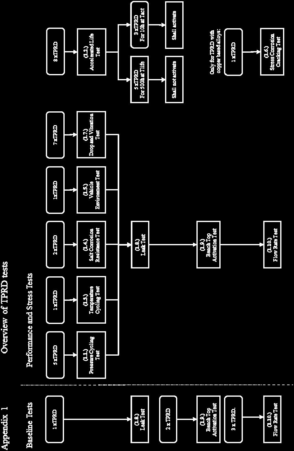
54 Annex 4 Appendix 1 54


55 Annex 4 Appendix 2 55
Draft Regulation on hydrogen and fuel cell vehicles
 Submitted by the expert from OICA Informal document GRSP-55-28-Rev.2 (55 th GRSP, 19-25 May 2014, agenda item 19) Deleted: 1 Draft Regulation on hydrogen and fuel cell vehicles Deleted: and Submitted by
E/ECE/324/Rev.2/Add.133 E/ECE/TRANS/505/Rev.2/Add.133
 25 June 2015 Agreement Concerning the Adoption of Uniform Technical Prescriptions for Wheeled Vehicles, Equipment and Parts which can be Fitted and/or be Used on Wheeled Vehicles and the Conditions for
Proposal for amendment to global technical regulation No.13 (Hydrogen and fuel cell vehicles)
") Submitted by the experts of the European Commission Informal document GRSP-54-11 (54 th GRSP, 17-20 December 2013, agenda item 22(g)) Page 1 Proposal for amendment to global technical regulation No.13
Submitted by the experts of the European Commission Informal document GRSP-54-11 (54 th GRSP, 17-20 December 2013, agenda item 22(g)) Page 1 Proposal for amendment to global technical regulation No.13
A Rationale for Pressure Relief Device(s) Qualification Requirements (LH2)
 Qualification Requirements (LH2)") UN-GTR PART A INSERTION Stand 09.02.2011, 17:20 Uhr A.3.3 HYDROGEN STORAGE SYSTEM The hydrogen storage system consists of all components that form the primary pressure boundary of the stored hydrogen in
UN-GTR PART A INSERTION Stand 09.02.2011, 17:20 Uhr A.3.3 HYDROGEN STORAGE SYSTEM The hydrogen storage system consists of all components that form the primary pressure boundary of the stored hydrogen in
BMW proposal for. Technical requirements concerning LIQUID HYDROGEN STORAGE SYSTEMS. for the use in hydrogen powered road vehicles
 BMW Draft, based on TRANS/WP.29/GRPE/2003/14 page 1 SGS 3-8 BMW proposal for Technical requirements concerning LIQUID HYDROGEN STORAGE SYSTEMS for the use in hydrogen powered road vehicles BMW Draft, based
ST/SG/AC.10/C.3/2016/8. Secretariat. United Nations. Transport of gas tanks for motor vehicles. Introduction
 United Nations Secretariat Distr.: General 29 March 2016 ST/SG/AC.10/C.3/2016/8 Original: English Committee of Experts on the Transport of Dangerous Goods and on the Globally Harmonized System of Classification
ANNEX AMENDMENTS TO THE INTERNATIONAL CODE FOR FIRE SAFETY SYSTEMS (FSS CODE) CHAPTER 15 INERT GAS SYSTEMS
 CHAPTER 15 INERT GAS SYSTEMS") Annex 3, page 2 ANNEX AMENDMENTS TO THE INTERNATIONAL CODE FOR FIRE SAFETY SYSTEMS (FSS CODE) CHAPTER 15 INERT GAS SYSTEMS The text of existing chapter 15 is replaced by the following: "1 Application This
Annex 3, page 2 ANNEX AMENDMENTS TO THE INTERNATIONAL CODE FOR FIRE SAFETY SYSTEMS (FSS CODE) CHAPTER 15 INERT GAS SYSTEMS The text of existing chapter 15 is replaced by the following: "1 Application This
E/ECE/324/Rev.2/Add.109/Rev.2 E/ECE/TRANS/505/Rev.2/Add.109/Rev.2
 19 August 2013 Agreement Concerning the Adoption of Uniform Technical Prescriptions for Wheeled Vehicles, Equipment and Parts which can be Fitted and/or be Used on Wheeled Vehicles and the Conditions for
Transport of gas tanks for motor vehicles
 United Nations Secretariat ST/SG/AC.10/C.3/2016/51 Distr.: General 30 August 2016 Original: English Committee of Experts on the Transport of Dangerous Goods and on the Globally Harmonized System of Classification
Transport of gas tanks for motor vehicles
 Committee of Experts on the Transport of Dangerous Goods and on the Globally Harmonized System of Classification and Labelling of Chemicals Transport of gas tanks for motor vehicles Submitted by the expert
E/ECE/324/Rev.1/Add.66/Rev.4/Amend.1 E/ECE/TRANS/505/Rev.1/Add.66/Rev.4/Amend.1
 5 November 2018 Agreement Concerning the Adoption of Harmonized Technical United Nations Regulations for Wheeled Vehicles, Equipment and Parts which can be Fitted and/or be Used on Wheeled Vehicles and
E/ECE/324/Rev.1/Add.66/Rev.4 E/ECE/TRANS/505/Rev.1/Add.66/Rev.4
 16 October 2014 Agreement Concerning the Adoption of Uniform Technical Prescriptions for Wheeled Vehicles, Equipment and Parts which can be fitted and/or be used on Wheeled Vehicles and the Conditions
This test shall be carried out on all vehicles equipped with open type traction batteries.
 5.4. Determination of hydrogen emissions page 1 RESS-6-15 5.4.1. This test shall be carried out on all vehicles equipped with open type traction batteries. 5.4.2. The test shall be conducted following
INTERNATIONAL ASSOCIATION OF CLASSIFICATION SOCIETIES. Interpretations of the. IGF Code
 INTERNATIONAL ASSOCIATION OF CLASSIFICATION SOCIETIES s of the IGF Code CONTENTS GF1 Test for gas fuel tank s high level alarm Rev.1 July 2017 GF2 Ship Steel Protection against Liquefied Gas Fuel (Part
[Reserved] Packagings ICC 3 1 3AA 3AL 3AX 3A480X 3AAX
![[Reserved] Packagings ICC 3 1 3AA 3AL 3AX 3A480X 3AAX](/thumbs/80/80792632.jpg "[Reserved] Packagings ICC 3 1 3AA 3AL 3AX 3A480X 3AAX") 173.300 [Reserved] 173.301 General requirements for shipment of compressed gases and other hazardous materials in cylinders, UN pressure receptacles and spherical pressure vessels. (a) General qualifications
173.300 [Reserved] 173.301 General requirements for shipment of compressed gases and other hazardous materials in cylinders, UN pressure receptacles and spherical pressure vessels. (a) General qualifications
RESOLUTION A.567(14) adopted on 20 November 1985 REGULATION FOR INERT GAS SYSTEMS ON CHEMICAL TANKERS
 adopted on 20 November 1985 REGULATION FOR INERT GAS SYSTEMS ON CHEMICAL TANKERS") INTERNATIONAL MARITIME ORGANIZATION A 14/Res.567 16 January 1986 Original: ENGLISH ASSEMBLY - 14th session Agenda item lo(b) IMO RESOLUTION A.567(14) adopted on 20 November 1985 THE ASSEMBLY, RECALLING
INTERNATIONAL MARITIME ORGANIZATION A 14/Res.567 16 January 1986 Original: ENGLISH ASSEMBLY - 14th session Agenda item lo(b) IMO RESOLUTION A.567(14) adopted on 20 November 1985 THE ASSEMBLY, RECALLING
International Civil Aviation Organization DANGEROUS GOODS PANEL (DGP) MEETING OF THE WORKING GROUP OF THE WHOLE. Montreal, 18 to 22 April 2005
 MEETING OF THE WORKING GROUP OF THE WHOLE. Montreal, 18 to 22 April 2005") International Civil Aviation Organization WORKING PAPER 24/3/05 DANGEROUS GOODS PANEL (DGP) MEETING OF THE WORKING GROUP OF THE WHOLE Montreal, 18 to 22 April 2005 Agenda Item 2: Development of recommendations
International Civil Aviation Organization WORKING PAPER 24/3/05 DANGEROUS GOODS PANEL (DGP) MEETING OF THE WORKING GROUP OF THE WHOLE Montreal, 18 to 22 April 2005 Agenda Item 2: Development of recommendations
An Urgent Bulletin from CSA Group
 An Urgent Bulletin from CSA Group Gas Products No. 335 (Supersedes Notice Gas Products No. 270, Ref No: N12-055) Effective Date: October 1, 2015 Date: July 21, 2014 Apply Before February 2, 2015 Announcing:
Informal document regarding progress of CEN standards for reference in RID/ADR
 Joint Meeting of the RID Safety Committee and the Working Party on the Transport of Dangerous Goods (Berne, 13-24 March 2000) Informal document regarding progress of CEN standards for reference in RID/ADR
Pressure Equipment Directive PED 2014/68/EU Commission's Working Group "Pressure"
 H. INTERPRETATION OF OTHER ESSENTIAL SAFETY REQUIREMENTS Guideline H-02 Guideline related to: Annex I Section 3.2.2 and 7.4 Final assessment (Annex I Section 3.2.2) of pressure equipment must include a
HANDBOOK SAFETY DEVICES. Ed SAFETY DEVICES DS-ED 01/ ENG 1
 HANDBOOK Ed. 2017 DS-ED 01/2017 - ENG 1 CHAPTER 9 BURSTING DISC DEVICES IN SERIES 3070 SCOPE Use: protection against possible overpressure of the apparatuses listed below, with regard to the operating
Savard Labor & Marine Staffing, Inc. Compressed Gas Safety Program Rev3/14
 Compressed Gas Safety Program Purpose: The purpose of this safety policy and procedure is to establish guidelines for the protection and safety of this company s employees who handle and use compressed
ISO INTERNATIONAL STANDARD. Small craft Liquefied petroleum gas (LPG) systems
 systems") INTERNATIONAL STANDARD ISO 10239 Second edition 2008-02-15 Small craft Liquefied petroleum gas (LPG) systems Petits navires Installations alimentées en gaz de pétrole liquéfiés (GPL) Reference number ISO
INTERNATIONAL STANDARD ISO 10239 Second edition 2008-02-15 Small craft Liquefied petroleum gas (LPG) systems Petits navires Installations alimentées en gaz de pétrole liquéfiés (GPL) Reference number ISO
BRITISH STANDARD BS 341-4: Transportable gas container valves. Part 4: Pressure relief devices ICS
 BRITISH STANDARD BS 341-4:2004 Transportable gas container valves Part 4: Pressure relief devices ICS 23.060.40 This British Standard, having been prepared under the direction of the Standards Policy and
CPX EMERGENCY STANDBY MANIFOLD INSTALLATION, OPERATIONS & MAINTENANCE MANUAL
 CPX EMERGENCY STANDBY MANIFOLD INSTALLATION, OPERATIONS & MAINTENANCE MANUAL Company Registered Office: Crown House, Stockport, Cheshire, SK13RB No. 850 0700 67 Registered in England and Wales No. 05058855
Pressure Equipment Directive (PED) 97/23/EC Page 033 of 124
 97/23/EC Page 033 of 124") Pressure Equipment Directive (PED) 97/23/EC Page 033 of 124 13.7 Pressure Equipment Directive (PED) 97/23/EC 1 The Pressure Equipment Directive (PED) 97/23/EC applies to the design, manufacturing and conformity
Pressure Equipment Directive (PED) 97/23/EC Page 033 of 124 13.7 Pressure Equipment Directive (PED) 97/23/EC 1 The Pressure Equipment Directive (PED) 97/23/EC applies to the design, manufacturing and conformity
P-04 Stainless Steel Corrugated Hoses and Metal Bellows Expansion Joints
 Guideline No.P-04 (201510) P-04 Stainless Steel Corrugated Hoses and Metal Bellows Expansion Joints Issued date: 20 th October 2015 China Classification Society Foreword This Guideline is a part of CCS
Hydrogen-Powered Vehicles: A Comparison of the European Legislation and the Draft UNECE Global Technical Regulation
 Hydrogen-Powered Vehicles: A Comparison of the European Legislation and the Draft UNECE Global Technical Regulation by C Visvikis CPR1187 SI2.575155 CLIENT PROJECT REPORT Transport Research Laboratory
FLAMMABLE GASES AND FLAMMABLE CRYOGENIC FLUIDS
 CHAPTER 35 FLAMMABLE GASES AND FLAMMABLE CRYOGENIC FLUIDS SECTION 3501 GENERAL 3501.1 Scope. The storage and use of flammable gases shall be in accordance with this chapter. Compressed gases shall also
Limited quantities of compressed gases.
 173.306 Limited quantities of compressed gases. (a) Limited quantities of compressed gases for which exceptions are permitted as noted by reference to this section in 172.101 of this subchapter are excepted
Lockout/Tagout CE Marking Requirements WHITE PAPER
 The CE mark is used to assert that a particular product meets one or more of just over 20 European Directives. (IE: EMC Directive, Machinery Directive, Safety of Toys, etc). Taking into consideration the
RULES PUBLICATION NO. 119/P
 RULES PUBLICATION NO. 119/P PERIODIC SURVEYS OF FUEL INSTALLATIONS ON SHIPS OTHER THAN LIQUEFIED GAS CARRIERS UTILIZING GAS OR OTHER LOW FLASH POINT FUELS 2019 January Publications P (Additional Rule Requirements)
M-06 Nitrogen Generator (Nitrogen Making Machine)
") Guideline No.M-06 (201510) M-06 Nitrogen Generator (Nitrogen Making Machine) Issued date: 20 th October, 2015 China Classification Society Foreword This Guideline is a part of CCS Rules, which contains
Guideline No.M-06 (201510) M-06 Nitrogen Generator (Nitrogen Making Machine) Issued date: 20 th October, 2015 China Classification Society Foreword This Guideline is a part of CCS Rules, which contains
Installation of Ballast Water Management Systems
 (Sept 2015) (Rev.1 May 2016) Installation of Ballast Water Management Systems 1. Application In addition to the requirements contained in BWM Convention (2004), the following requirements are applied to
Smart Water Application Technologies (SWAT) TM
 TM") Smart Water Application Technologies (SWAT) TM Equipment Functionality Test Protocol Version 2.3 June 2014 SWAT Committee 8280 Willow Oaks Corporate Drive Suite 400 Fairfax, VA 22031 www.irrigation.org
Smart Water Application Technologies (SWAT) TM Equipment Functionality Test Protocol Version 2.3 June 2014 SWAT Committee 8280 Willow Oaks Corporate Drive Suite 400 Fairfax, VA 22031 www.irrigation.org
Information on work in progress in CEN
 Economic Commission for Europe Inland Transport Committee Working Party on the Transport of Dangerous Goods Joint Meeting of the RID Committee of Experts and the Working Party on the Transport of Dangerous
Liquefied gas cargo tanks and process pressure vessels
 .1 -.3 Liquefied gas cargo tanks and process pressure vessels.1 General.1.1 The present texts give the general principles which are applied by Classification Societies for approval and survey of the relevant
Translation Principles of testing and certification for insulating hose assemblies on cable cutting devices
 Translation Principles of testing and certification for insulating hose assemblies on cable cutting devices Status as of 2014-01 Principles of testing Insulating hose assemblies on cable cutting devices
IDEM Indiana Department of Environmental Management Office of Land Quality P.O. Box 6015 Indianapolis, IN OLQ PH: (317)
") IDEM Indiana Department of Environmental Management Office of Land Quality P.O. Box 6015 Indianapolis, IN 46206-6015 OLQ PH: (317) 232-8941 Information SUBPART CC AIR EMISSION STANDARDS (40 CFR 264.1080
IDEM Indiana Department of Environmental Management Office of Land Quality P.O. Box 6015 Indianapolis, IN 46206-6015 OLQ PH: (317) 232-8941 Information SUBPART CC AIR EMISSION STANDARDS (40 CFR 264.1080
BCGA GUIDANCE NOTE 17
 BCGA GUIDANCE NOTE 17 BCGA POLICY AND GUIDANCE FOR THE SAFE FILLING OF THIRD-PARTY OWNED AND / OR MAINTAINED TANKS Revision 2: 2013 BCGA GUIDANCE NOTE 17 BCGA POLICY AND GUIDANCE FOR THE SAFE FILLING OF
Periodic Survey of Fuel Installations on Ships other than Liquefied Gas Carriers utilizing gas or other low flash point fuels
 (Jan 2017) Periodic Survey of Fuel Installations on Ships other than Liquefied Gas Carriers utilizing gas or other low flash point fuels CONTENTS 1. Application 2. Special Survey 2.1 Schedule 2.2 Scope
Pressure Equipment Directive PED 2014/68/EU Commission's Working Group "Pressure"
 C. ASSEMBLIES Guideline C-03 Guideline related to: Article 4 paragraph 2 The effect of the derogation in Article 4 paragraph 2 from the introductory paragraph in the same article is not clear. In the circumstances,
Pressure Automated Calibration Equipment
 GE Measurement & control Pressure Automated Calibration Equipment Safety Instructions and User Guide - K0447 PACE5000 PACE6000 K0447 Issue No. 9 1 10 1 PACE5000 1 2 3 4 5 PACE6000 2 6 7 8 3 4 5 6 7 8 9
AGREEMENT. (Revision 2, including the amendments entered into force on 16 October 1995) Addendum 109: Regulation No. 110
 Addendum 109: Regulation No. 110") 19 June 2001 AGREEMENT CONCERNING THE ADOPTION OF UNIFORM TECHNICAL PRESCRIPTIONS FOR WHEELED VEHICLES, EQUIPMENT AND PARTS WHICH CAN BE FITTED AND/OR BE USED ON WHEELED VEHICLES AND THE CONDITIONS FOR
19 June 2001 AGREEMENT CONCERNING THE ADOPTION OF UNIFORM TECHNICAL PRESCRIPTIONS FOR WHEELED VEHICLES, EQUIPMENT AND PARTS WHICH CAN BE FITTED AND/OR BE USED ON WHEELED VEHICLES AND THE CONDITIONS FOR
Flexible hoses - Non-metallic materials
 CLASS PROGRAMME Type approval DNVGL-CP-0183 Edition December 2015 The electronic pdf version of this document, available free of charge from http://www.dnvgl.com, is the officially binding version. FOREWORD
East Building, PHH-30 U.S. Department New Jersey Avenue S.E. of Transportation Washington, D.C EXPIRATION DATE: June 30, 2015
 November 14, 2014 East Building, PHH-30 U.S. Department 1200 New Jersey Avenue S.E. of Transportation Washington, D.C. 20590 Pipeline and Hazardous Materials Safety Administration DOT-SP 16219 EXPIRATION
INSTRUCTIONS FOR MODELS SG3897 AND SG3898 CROSS PURGE ASSEMBLIES
 INSTRUCTIONS FOR MODELS SG3897 AND SG3898 CROSS PURGE ASSEMBLIES THIS BOOKLET CONTAINS PROPRIETARY INFORMATION OF ADVANCED SPECIALTY GAS EQUIPMENT CORP. AND IS PROVIDED TO THE PURCHASER SOLELY FOR USE
EXPIRATION DATE: (FOR RENEWAL, SEE 49 CFR ) 1. GRANTEE: Structural Composites Industries (SCI) Pomona, CA
 1. GRANTEE: Structural Composites Industries (SCI) Pomona, CA") East Building, PHH-30 1200 New Jersey Avenue S.E. U.S. Department of Transportation Washington, D.C. 20590 Pipeline and Hazardous Materials Safety Administration DOT-SP 13583 (NINTH REVISION) EXPIRATION
East Building, PHH-30 1200 New Jersey Avenue S.E. U.S. Department of Transportation Washington, D.C. 20590 Pipeline and Hazardous Materials Safety Administration DOT-SP 13583 (NINTH REVISION) EXPIRATION
HYDROSTATIC LEAK TEST PROCEDURE
 This information is proprietary and shall not be disclosed outside your organization, nor shall it be duplicated, used or disclosed for purposes other than as permitted under the agreement with Kinetics
Compressed Gas Cylinders - Guideline
 Environmental Health and Safety Compressed Gas Cylinders - Guideline Date of Issuance: 1/10/18 Revision Number: Initial Revision Date: Prepared by: EH&S 1. Purpose Carnegie Mellon University has developed
Economic and Social Council
 United Nations Economic and Social Council ECE/TRANS/WP.29/2013/101 Distr.: General 31 July 2013 Original: English Economic Commission for Europe Inland Transport Committee World Forum for Harmonization
Guideline No.M-05(201510) M-05 AIR COMPRESSOR. Issued date: 20 October China Classification Society
 M-05 AIR COMPRESSOR. Issued date: 20 October China Classification Society") Guideline No.M-05(201510) M-05 AIR COMPRESSOR Issued date: 20 October 2015 China Classification Society Foreword This Guideline constitutes the CCS rules, and establishes the applicable technical requirements
Guideline No.M-05(201510) M-05 AIR COMPRESSOR Issued date: 20 October 2015 China Classification Society Foreword This Guideline constitutes the CCS rules, and establishes the applicable technical requirements
Economic and Social Council
 United Nations Economic and Social Council Distr.: General 27 February 2015 Original: English Economic Commission for Europe Inland Transport Committee World Forum for Harmonization of Vehicle Regulations
Pressure Systems Safety Regulation
 Pressure Systems Safety Regulation Introduction This document informs Faculty of the key requirements of the UK and Chinese Pressure Systems Safety regulations. The aim of these regulations is to prevent
Health and Safety at Work (Hazardous Substances Reduced Secondary Containment for Certain Above Ground Stationary Tanks) Safe Work Instrument 2017
 Safe Work Instrument 2017") Health and Safety at Work (Hazardous Substances Reduced Secondary Containment for Certain Above Ground Stationary Tanks) Safe Work Instrument 2017 This safe work instrument is approved under section 227
Health and Safety at Work (Hazardous Substances Reduced Secondary Containment for Certain Above Ground Stationary Tanks) Safe Work Instrument 2017 This safe work instrument is approved under section 227
MANUAL GAS MANIFOLDS
 MANUAL GAS MANIFOLDS Phoenix Pipeline Products Limited. Unit 8, McKenzie Industrial Park, Tel No.: 44 (0) 161 428 7200 Bird Hall Lane, Fax No.: 44 (0) 161 428 7010 Stockport, Email: info@p3-phoenix.com
MSC Guidelines for Pressure Vessels
 References: a. 46 CFR Part 54 Pressure Vessels S. T. Brady, CDR, Chief, Engineering Division b. ASME Boiler and Pressure Vessel Code (BPVC), Section VIII, Division 1, (1998 Edition) c. Navigation and Inspection
PASSENGER SHIPS Guidelines for preparation of Hull Structural Surveys
 (Feb 2010) PASSENGER SHIPS Guidelines for preparation of Hull Structural Surveys Contents 1 Introduction 2 Preparations for Survey 2.1 General 2.2 Conditions for survey 2.3 Access to structures 2.4 Survey
Economic and Social Council
 United Nations Economic and Social Council Distr.: General 21 December 2017 Original: English Economic Commission for Europe Inland Transport Committee Working Party on the Transport of Dangerous Goods
Periodical surveys of cargo installations on ships carrying liquefied gases in bulk
 (June 1999) (Rev.1 Mar 2006) (Rev.2 May 2007) (Rev.3 Mar 2010) (Corr.1 Feb 2011) (Rev.4 Oct 2013) Periodical surveys of cargo installations on ships carrying liquefied gases in bulk 1 General 1.1 Scope
INTERNATIONAL MARITIME ORGANIZATION
 Page 1 of 16 INTERNATIONAL MARITIME ORGANIZATION IMO Resolution A.586(14) REVISED GUIDELINES AND SPECIFICATIONS FOR OIL DISCHARGE MONITORING AND CONTROL SYSTEMS FOR OIL TANKERS. ANNEX This document quote
Gas Injection Systems
 NSF International Recreational Water Program Component Certification Specification CCS-14530 Gas Injection Systems The Public Health and Safety Company. TM NSF Recreational Water Program Component Certification
Airfix D-E-B Installation and operating instructions
 www.flamco.nt-rt.ru Airfix D-E-B Installation and operating instructions Dear Customer, With the Airfix D-E-B membrane expansion vessel you have acquired a Flamco quality product. This expansion vessel
Rules for the Installation, Inspection and Testing of Air Reservoirs (Other than on Locomotives)
") Rules for the Installation, Inspection and Testing of Air Reservoirs (Other than on Locomotives) December 5, 1994 TM Rules for the Installation, Inspection and Testing of Air Reservoirs (Other than on
Rules for the Installation, Inspection and Testing of Air Reservoirs (Other than on Locomotives) December 5, 1994 TM Rules for the Installation, Inspection and Testing of Air Reservoirs (Other than on
I. Subject: Compressed gas cylinders, regulators, and portable liquid systems.
 I. Subject: Compressed gas cylinders, regulators, and portable liquid systems. II. Objective: To provide safe and effective use, storage, and transport of therapeutic gases. II. Procedure: A. Compressed
TABLE OF CONTENTS PART 2 - CONFINED SPACES
 May 11, 2006 TABLE OF CONTENTS PART 2 - CONFINED SPACES Page DEFINITIONS... 2-1 GENERAL... 2-2 RESPONSIBILITIES... 2-2 HAZARD ASSESSMENT AND WORK PROCEDURES... 2-3 IDENTIFICATION AND ENTRY PERMITS... 2-3
The evolution of the Ex-proof flame path
 April 2017 The evolution of the Ex-proof flame path As written in previous dissertation, the most critical part of a flameproof enclosure 'Ex d' is the flame path. Although the Standards are divided into
ASSE International Product (Seal) Listing Program
 Listing Program") ASSE International Product (Seal) Listing Program ASSE 1070-2015 / ASME A112.1070-2015 / CSA B125.70-15 Performance Requirements for Water Temperature Limiting Devices Manufacturer: Contact Person: E-mail:
ASSE International Product (Seal) Listing Program ASSE 1070-2015 / ASME A112.1070-2015 / CSA B125.70-15 Performance Requirements for Water Temperature Limiting Devices Manufacturer: Contact Person: E-mail:
TECHNICAL DATA MAINTENANCE AIR COMPRESSOR MODEL G-1
 Dry 131h 1. DESCRIPTION The Viking Model G-1 Maintenance Air Compressor is an electric motor-driven, aircooled, single-stage, oil-less compressor. The unit is equipped with a check valve and provides a
ontario regulation 629/05 made under the occupational health and safety act
 ontario regulation 629/05 made under the occupational health and safety act Made: December 7, 2005 Filed: December 8, 2005 Published on e-laws: December 9, 2005 Printed in The Ontario Gazette: December
PRESSURE RETEST. 49 CFR, (g) Co#: Vin#: DOT Spec: MAWP:
 Co#: Vin#: DOT Spec: MAWP:") PRESSURE RETEST 49 CFR, 180.407(g) Co#: Vin#: Spec: MAWP: Retest Date: Location: *External Inspection Performed: *Internal Inspection Performed: Test Pressure: psig Held for: min. (Must be at least 10
PRESSURE RETEST 49 CFR, 180.407(g) Co#: Vin#: Spec: MAWP: Retest Date: Location: *External Inspection Performed: *Internal Inspection Performed: Test Pressure: psig Held for: min. (Must be at least 10
High-Pressure Boiler Inspection Procedures: A Complete Checklist
 High-Pressure Boiler Inspection Procedures: A Complete Checklist Inspecting high-pressure boilers is a complex process requiring preparation, planning, and a multitude of safety precautions. Regular inspections
Spilt body Flange ball valve. TC-205MFF-PN1640 User Manual English Version. Document No: TC-205MFF-PN1640.Ur-manual. Date: 2007/04/2617. Version: 1.
 Spilt body Flange ball valve TC-205MFF-PN1640 Series PED Category I,II TC-205MFF-PN1640 User Manual English Version Use for company in Europe who will place the product on the market, please amend which
PURPOSE OF THE POLICY
 Title: Safe Storage, Handling, Use and Disposal Procedures of Compressed Gas Cylinders Effective Date: November 2005 Revision Date: March 1, 2017 Issuing Authority: Responsible Officer: VP, Capital Projects
Summary of the MRA LPG Codes of Practice
 Summary of the MRA LPG Codes of Practice COP A1 DESIGN and INSTALLATION Code COP A1 deals with above ground installations where LPG is stored under pressure at ambient temperatures in fixed vessels larger
CHAPTER 1 General Part
 1 (Garuda Emblem) Notification of Ministry of Industry Re: Safety measure for gas business operation B.E. 2548 (2005) ---------------------------- By the virtue of clause 18 and clause 19 of the Ministerial
Occupational Health and Safety Act
 Page 1 of 16 Français Occupational Health and Safety Act ONTARIO REGULATION 632/05 CONFINED SPACES Consolidation Period: From March 29, 2011 to the e-laws currency date. Last amendment: O. Reg. 95/11.
VALVE MANUFACTURERS ASSOCIATION API 622 API 624
 VALVE MANUFACTURERS ASSOCIATION API 622 API 624 Written by Rich Davis Manager Business Development Western Hemisphere & China Flexitallic L.P., Deer Park, Texas Presented By: Steve Butler, Shell Global
 National Fire Protection Association Report http://submittals.nfpa.org/terraviewweb/contentfetcher?commentparams=%28comment... Page 1 of 2 1/16/2014 Committee Input No. 104-NFPA 55-2013 [ Global Input
Standard Pneumatic Test Procedure Requirements for Piping Systems
 the pressure equipment safety authority Standard Pneumatic Test Procedure Requirements for Piping Systems AB-522 Edition 2, Rev. 1 Issued 2016-10-24 Table of Contents FOREWORD... 1 1.0 INTRODUCTION...
IMO. Amendments to the IMDC Code, its annexes and supplements. Proposal for an MSC Circular on IMO Type Portable Tanks
 INTERNATIONAL MARITIME ORGANIZATION E IMO SUB-COMMITTEE ON DANGEROUS GOODS, SOLID CARGOES AND CONTAINERS 7th session Agenda item 3 DSC 7/3/5 20 June 2002 Original: ENGLISH AMENDMENTS TO THE IMDG CODE,
PREVENTION OF EXCESSIVE PRESSURE DURING FILLING OF CRYOGENIC VESSELS
 PREVENTION OF EXCESSIVE PRESSURE DURING FILLING OF CRYOGENIC VESSELS AIGA 054/08 GLOBALLY HARMONISED DOCUMENT Asia Industrial Gases Association 3 HarbourFront Place, #09-04 HarbourFront Tower 2, Singapore
Installation Instructions and valve Maintenance Rev. 0 of 29/09/15
 Pag1 ASSEMBLING PROCEDURE AND VALVE MAINTENANCE 1.0.... Safety Information 2.0.. INTRODUCTION 3.0 VARIATIONS 4.0..ASSEMBLING PROCEDURE FOR THE STEM 5.0 ASSEMBLING PROCEDURE FOR OUTLET CONNECTIONS 6.0 PROCEDURE
CAST IRON SAFETY VALVE TYPE 6301
 CHARACTERISTICS The 6301 safety valve is dedicated to protect the equipment from potential overpressure. This is an automatic device that closes when the pressure conditions are back to normal. It is a
F All types of inert gas systems are to comply with the following:
 (1974) (Rev.1 1983) (Rev.2 1987) (Rev.3 May 1998) (Corr. Sept 2001) (Rev.4 May 2004) (Rev.5 Nov 2005) (Rev.6 May 2012) (Rev.7 May 2015) Inert Gas Systems.1 General Requirements.1.1 All types of inert gas
East Building, PHH-30 U.S. Department New Jersey Avenue S.E. of Transportation Washington, D.C DOT-SP (FOURTH REVISION)
") East Building, PHH-30 U.S. Department 1200 New Jersey Avenue S.E. of Transportation Washington, D.C. 20590 Pipeline and Hazardous Materials Safety Administration DOT-SP 15260 (FOURTH REVISION) EXPIRATION
East Building, PHH-30 U.S. Department 1200 New Jersey Avenue S.E. of Transportation Washington, D.C. 20590 Pipeline and Hazardous Materials Safety Administration DOT-SP 15260 (FOURTH REVISION) EXPIRATION
East Building, PHH-30 U.S. Department New Jersey Avenue S.E. of Transportation Washington, D.C DOT-SP (NINTH REVISION)
") East Building, PHH-30 U.S. Department 1200 New Jersey Avenue S.E. of Transportation Washington, D.C. 20590 Pipeline and Hazardous Materials Safety Administration DOT-SP 14576 (NINTH REVISION) EXPIRATION
East Building, PHH-30 U.S. Department 1200 New Jersey Avenue S.E. of Transportation Washington, D.C. 20590 Pipeline and Hazardous Materials Safety Administration DOT-SP 14576 (NINTH REVISION) EXPIRATION
10 December 2010 GUIDANCE FOR WATERTIGHT DOORS ON PASSENGER SHIPS WHICH MAY BE OPENED DURING NAVIGATION
 E 4 ALBERT EMBANKMENT LONDON SE1 7SR Telephone: +44 (0)20 7735 7611 Fax: +44 (0)20 7587 3210 Ref. T4/3.01 MSC.1/Circ.1380 10 December 2010 GUIDANCE FOR WATERTIGHT DOORS ON PASSENGER SHIPS WHICH MAY BE
Vehicle- or rack-mounted liquefied gas meters, pump supplied
 Purpose This inspection procedure outline (IPO) defines the minimum tests which must be performed to ensure that basic volumetric measuring devices comply with the legislation. Application Rack/fixed metering
5.0 INSPECTING, FILLING AND LABELING SMALL CYLINDERS
 5.0 INSPECTING, FILLING AND LABELING SMALL CYLINDERS 23 24 5.0 INSPECTING, FILLING AND LABELING SMALL CYLINDERS INSPECTING, FILLING AND LABELING SMALL CYLINDERS Pre-fill Visual Check Safely inspecting
AUTOMATIC GAS MANIFOLDS
 AUTOMATIC GAS MANIFOLDS Phoenix Pipeline Products Limited. Unit 8, McKenzie Industrial Park, Tel No.: 44 (0) 161 428 7200 Bird Hall Lane, Fax No.: 44 (0) 161 428 7010 Stockport, Email: info@p3-phoenix.com
Horizontal Bladder Tanks
 DATA SHEET Horizontal Bladder Tanks Features UL Listed and FM Approved for use with various ANSUL proportioners and foam concentrates 175 psi (12.1 bar) maximum allowable working pressure (design pressure)
WP2 Fire test for toxicity of fire effluents
 Pagina 3 di 89 TRA SFEU VTT 22.6.2009 v.2 WP2 Fire test for toxicity of fire effluents Task 2.1.2 Development of small-scale test method for fire effluents Step 1: Use of modeling Plans according to DoW:
Vehicle-mounted meters, pump supplied
 Purpose This inspection procedure outline (IPO) defines the minimum tests which must be performed to ensure that basic volumetric measuring devices comply with the legislation. Application Vehicle-mounted
MARIPOSA COUNTY LOCKOUT/TAGOUT PROGRAM
 MARIPOSA COUNTY LOCKOUT/TAGOUT PROGRAM INTRODUCTION Mariposa County ( County ) facilities have equipment and systems that must be deenergized to allow for safe cleaning, repairing, servicing, setting-up,
PSSI 36 General Confined Spaces, Tunnels, Culverts and Similar Spaces
 1. SCOPE This document now includes provision for safe access to cable tunnels and culverts previously covered in PSSI 37 which is now withdrawn. The term Confined Space is defined in the Confined Spaces
Preparation and Installation of the Sanitary BDI-FLX Sensor and Connection to the BDI-FLX Interface Cable
 GEP-6075 Rev. B 101574 Ref. I.D.: 16973 Preparation and Installation of the Sanitary BDI-FLX Sensor and Connection to the BDI-FLX Interface Cable WARNING USER SHOULD READ AND THOROUGHLY UNDERSTAND THESE
POP Safety Valve. POP Safety Valve INTRODUCTION DEFINITIONS
 POP Safety Valve POP Safety Valve INTRODUCTION The effects of exceeding safe pressure levels in an unprotected pressure vessel or system, can have catastrophic effects on both plant and personnel. Safety
THE STUDY ON THE INTERNAL TEMPERATURE CHANGE OF TYPE 3 AND TYPE 4 COMPOSITE CYLINDER DURING FILLING
 THE STUDY ON THE INTERNAL TEMPERATURE CHANGE OF TYPE AND TYPE COMPOSITE CYLINDER DURING FILLING Kim, ChangJong, Cho, Sung Min, Kim, Eun Jung and Yoon, Kee Bong Institute of Gas Safety R&D, Korea Gas Safety
HANDBOOK SAFETY DEVICES. Ed SAFETY DEVICES DS-ED 01/ ENG 1
 HANDBOOK Ed. 2017 DS-ED 01/2017 - ENG 1 2 DS-ED 01/2017 - ENG INDEX CHAPTER 1 Safety valves in series 3030 CHAPTER 2 Safety valves in series 3060 CHAPTER 3 Safety valves in series 3061 CHAPTER 4 Safety