These instructions must be left with the user
|
|
|
- Sophie Edwards
- 5 years ago
- Views:
Transcription

1 Mira Vier These instructions must be left with the user 1
2 Installation Guide CONTENTS If you experience any difficulty with the installation or operation of your new shower, then please refer to the Fault Diagnosis section, before contacting Kohler Mira Ltd. Our telephone and fax numbers can be found in the back of this guide. INTRODUCTION Thank you for purchasing a quality Mira product. To enjoy the full potential of your new product, please take time to read this guide thoroughly. Having done so, keep it handy for future reference. The Mira Vier Mixer Valve is designed to be used with the Mira Vier showerhead and fittings. Products Covered by this Guide Mira Vier Digital Mixer - High Pressure/Combi Valve Mira Vier Digital Mixer - Pumped Valve. Mira Vier Wireless Controller. Mira 360 Fittings (Ceiling Fed or Rear Fed). Guarantee For domestic installations, Mira Showers guarantee the Mira Vier against any defect in materials or workmanship for a period of five years from the date of purchase (shower fittings for one year). For non-domestic installations, Mira Showers guarantee the Mira Vier against any defect in materials or workmanship for a period of one year from the date of purchase. For terms and conditions refer to the back cover of this guide. Recommended Usage 2
3 Domestic Light Commercial Heavy Commercial Healthcare Patents and Design Registration Design Registration Patents GB: , USA: , Patent Applications UK: Europe: China: CN A India: 1306/MUMNP/2010 USA: US A1 WO: 2009/022112, 2009/ IMPORTANT SAFETY INFORMATION Warning! Follow all warnings, cautions and instructions contained in this guide, and on or inside the appliance. 1. THIS APPLIANCE MUST BE EARTHED. ENSURE SUPPLEMENTARY BONDING COMPLIES WITH THE REQUIREMENTS FOR ELECTRICAL INSTALLATIONS. The Mira Digital Mixer Valve is intended to be permanently connected to the fixed electrical wiring of the mains system. A means for electrical isolation of the appliance shall be provided in the fixed wiring in accordance with local wiring regulations. 2. Products manufactured by us are safe and risk-free, provided that they are installed, used and maintained in good working order, in accordance with our instructions and recommendations. 3. Isolate the electrical and water supplies before connecting to the appliance. 4. This appliance must be provided with means for disconnection that is incorporated into the fixed wiring in accordance with the relevant local wiring regulations. 5. Refer to the wiring diagram before making any electrical connections. 3
4 6. Mains connections are exposed when the cover of the Digital Mixer Valve is removed. 7. The Digital Mixer Valve must not be installed where it can become frozen. 8. Make sure that any pipework that could become frozen is properly insulated. 9. In accordance with BS7671 a 30mA Residual Current Device (RCD) should be included in the electrical circuit. This may be part of the consumer unit or a separate unit. 10. All pipework must be checked for leaks before the product installation is completed. The product should be pressurised and both inlet & outlet connections inspected. 11. If the shower is dismantled during installation or servicing then upon completion the product must be inspected to ensure all electrical connections are tight and that there are no leaks. 12. Having completed the installation, make sure that the user is familiar with the operation of the appliance. 13. DO NOT commission this appliance if water leaks from the unit. 14. Only Mira recommended outlet fittings should be used. 15. Ensure all electrical connections are tight, to prevent overheating. 16. This product is not suitable for areas with high humidity (i.e steam rooms). Please consult your installer. 17. The water supplies to this product must be isolated if the product is not to be used for a long period of time. If the product or pipework is at risk of freezing during this period they should also be drained of water. 4
5 Caution! 1. Read all of these instructions and retain this guide for later use. 2. The electrical installation must comply to BS Requirements for Electrical Installations commonly referred to as the IEE Wiring Regulations, or any particular regulations and practices, specified by the local electricity supply company. 3. The plumbing installation must comply with the requirements of UK Water Regulations / By-laws (Scotland), Building Regulations or any particular regulations and practices, specified by the local water company or water undertakers. 4. Make sure that you fully understand how to operate this shower and make sure that it is properly maintained in accordance with the instructions given in this manual. 5. Children should be supervised to make sure that they do not play with the appliance. 6. Anyone who may have difficulty understanding or operating the controls of the shower should be supervised whilst showering. Particular consideration should be given to: The young The elderly The infirm The disabled Anyone who suffers from a medical condition that can result in temporary incapacity (e.g. Epilepsy or blackouts). Anyone inexperienced in the correct operation of the controls. 7. The appliance is not intended for use by persons (including children) with reduced physical, sensory or mental capabilities, unless they are supervised or have been given instruction concerning the use of the appliance by a person responsible for their safety. Sunburn or skin conditions can increase your sensitivity to hot water. Make sure that you set the shower to a cooler temperature. 8. If any of the following conditions occur, isolate the electricity and water supplies and refer to section To contact us, in the back cover of this guide. If the cover is not correctly fitted and water has entered the appliance case. If the case is damaged. If the appliance begins to make an odd noise, smell or smoke. 5

6 If the appliance shows signs of a distinct change in performance, indicating a need for maintenance. 9. DO NOT operate if water leaks from the appliance. 10. DO NOT operate this appliance if it is frozen. If suspected of being frozen, isolate and contact us for advice. PACK CONTENTS Tick the appropriate boxes to familiarise yourself with the part names and to confirm that the parts are included. Documentation 1 x Wireless Controller User Guide 1 x Showerhead User Guide 1 x Customer Support Brochure Digital Mixer Valve 6
7 Wireless Controller 1 x Wireless 2 x Fixing Screws Controller 2 x Wall Plugs 1 x Wall Plate 3 x AA Batteries 7
8 Ceiling Fed Fittings 8

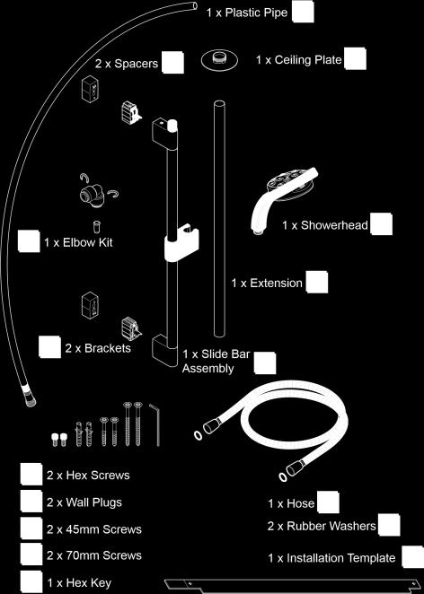
9 9


10 Rear Fed Fittings 1 x Right Angle Connector (RAC) Kit 1 x Right Angle 1 x Installation Template 10
11 Standards and Approvals Connector Shroud SPECIFICATIONS The Mira Vier complies with all relevant directives for CE marking. The Mira Vier is a type 1 electronic, independently mounted control for surface mounting. The Mira Vier is in compliance with the essential requirements of the R&TTE directive 1999/5/EC. A copy of the declaration of conformity may be obtained by contacting Kohler Mira Limited, U.K customer services department. General Pollution Degree 2 Rated Impulse Voltage Suitable for Drinking 2.5 kv Not Suitable Connections 15 mm Compression/Pushfit Mira Digital Mixer Valve High Pressure Pressures Maximum Static Pressure Maximum Maintained Pressure Minimum Maintained Pressure Supply Pressure Differential 1000 kpa (10 bar) = 100 m max. total head 500 kpa (5 bar) = 50 m max. total head 50 kpa (0.5 bar) = 5 m max. total head Nominally Equal Temperatures Maximum Temperature (factory preset) 45 C Maximum Temperature (setting range) 39 C - 48 C Minimum Temperature Thermostatic control down to 30 C Hot Water Range 55 C - 65 C Cold Water Range 1 C - 20 C Temperature Stability ± 1 C at recommended supply conditions 11
12 Ambient Temperature 1 C - 40 C Maximum Relative Humidity 95% non-condensing Flow Rates and Times Nominal Flow Rates (will vary depending on inlet maintained pressure and spray mode) 1.0 bar = 16l/min 1.0 bar = 5l/min Electrical Supply Voltage Maximum Load Mira Digital Mixer Valve Pumped Pressures Maximum Static Pressure Maximum Maintained Pressure Minimum Maintained Pressure Supply Pressure Differential 230V AC 50 Hz 20 W 100 kpa (1 bar) = 10 m max. total head 100 kpa (1 bar) = 10 m max. total head 1 kpa (0.01 bar) = 0.1 m min. total head Nominally Equal Temperatures Maximum Temperature (factory preset) 45 C Maximum Temperature (settable range) 39 C - 48 C Minimum Temperature Thermostatic control down to 30 C Full Cold also selectable Hot Water Range 50 C - 65 C Cold Water Range 1 C - 20 C Temperature Stability ± 1 C at recommended supply conditions Ambient Temperature 1 C - 40 C Maximum Relative Humidity 95% non-condensing at 30 C 12
13 Flow Rates and Times Flow Rates (will vary depending on inlet maintained pressure and spray mode) 0.01 bar = 16 l/min 0.01 bar = 6 l/min Electrical Supply Voltage Maximum Load 230V AC 50 Hz 200 W at 230V AC 13
14 DIMENSIONS 14
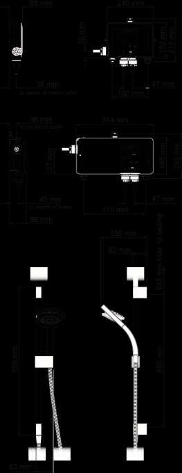
15 15
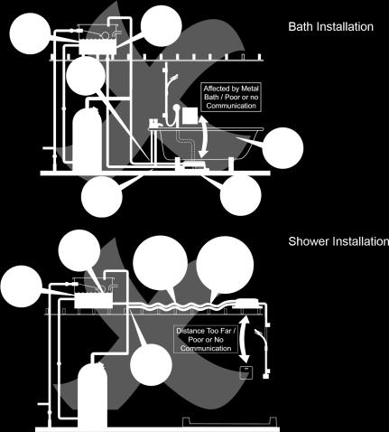
16 General INSTALLATION The installation must be carried out in accordance with these instructions, and must be conducted by designated, qualified and competent personnel. The Digital Mixer Valve may be installed in a loft space, under the bath or in a convenient cupboard space provided there is enough room for maintenance (e.g. Removal of Digital Mixer Valve lid). Failure to do so may result in an inability to carry out any maintenance. Safe and easy access to the product should be available at all times. When installing a mixer valve in an area not regularly accessed, consideration for potential leaks must be taken into account. While such events are unlikely, it is advisable to periodically check the installation for traces of water on or around the product. If possible, site the valve in a location where any leak would be contained or routed to avoid areas sensitive to water damage. Isolating valves must be installed to both inlets (supplied) and outlet, close to the Digital Mixer Valve for ease of maintenance. Caution! Risk of product damage. The Digital Mixer Valve must be installed in a dry, ventilated area where it will not freeze. Important Information Regarding Radio Controlled Devices Metal objects such as steel baths or sinks, cold water storage tanks, hot water cylinders, foil lined plaster board walls, radiators and even thick brick walls, can all dramatically reduce the radio operational range of any radio controlled product. Interference from other radio signals can dramatically reduce the ability of the Mira Vier User Interface / digital mixer to communicate. This may include; mobile phones, radio control boiler thermostats, wireless broadband routers, radio control toys, cordless phones, remote outdoor weather stations etc. Note! Failure to follow these guidelines can result in poor, intermittent or complete failure to communicate with the digital mixer. Typical Suitable Installations: 16

17 1. Instantaneous Multipoint Water Heaters and Combination Boilers Caution! Risk of product damage. Do not fit the Mira Digital Mixer - PUMPED VALVE with Instantaneous Multipoint Water Heaters or Combination Boilers. Key to Symbols Float Valve Isolating Valve Pressure Valve Reducing Tempering Valve Overflow Indicator Mini Expansion Vessel Only install the High Pressure Digital Mixer Valve with a multipoint gas water heater or combination boiler of a fully modulating design (i.e. where the water draw-off rate indirectly controls the gas flow rate to the burner). An expansion vessel must be fitted (and regularly maintained) if any form of backflow prevention device is fitted, e.g. non-return valve or PRV. This will ensure that excess expansion or pulse pressures do not damage the product or plumbing system. The expansion vessel may already be fitted within the boiler (check with the manufacturer) and is in addition to the normally larger central heating expansion vessel. 17

 if any form of backflow prevention device is fitted, e.g. non-return valve, PRV, then an expansion vessel should also be fitted.")
. 3.")
18 2. Mains Pressurised Instantaneous Hot Water Shower, Heated from a Thermal Store Caution! Risk of product damage. Do not fit the Mira Digital Mixer - PUMPED VALVE with Mains Pressurised Systems. Packages of this type, fitted with a tempering valve can be used. A drop type pressure reducing valve must be fitted (and regularly maintained) if any form of backflow prevention device is fitted, e.g. non-return valve, PRV, then an expansion vessel should also be fitted. This will ensure that excess expansion or pulse pressures do not damage the product or the plumbing system. The expansion vessel may already be fitted externally or internally within the thermal store (check with thermal store manufacturer). 3. Gravity Fed Showers Caution! Risk of product damage. Do not fit the Mira Digital Mixer - HIGH PRESSURE/COMBI VALVE with Gravity Fed Systems. 18
19 The shower control must be fed from a cold water storage cistern and a hot water cylinder providing nominally equal pressures. Pipework layouts and connections must be such that other draw-offs will not effect water supplies to the shower, shared supplies may lead to airlocking or water starvation. It is therefore best practice to have independent hot and cold supplies to the Low Pressure (pumped) Digital Mixer Valve. Typical Examples of Poor Plumbing and Installation Practices DO NOT: Install the Digital Mixer Valve where it can become frozen Position the Digital Mixer Valve where maintenance access is poor Install into a system where the cold water cistern holds less than 230 litres Install into a system where air locking could occur Install the user interface in a position where communication with the Digital Mixer Valve is poor e.g. mixer valve installed under metal bath, in front of metal cistern, more than the recommended distance away etc. Install the Digital Mixer Valve onto shared water supplies Install the Digital Mixer Valve less than 100 mm from the lowest level of water in the cistern Fit plastic pipework unless rigidly supported 19
20 20

21 Installation Schematic A separate, permanently connected supply must be taken from the ring main to the appliance through a 3 amp double pole switched fuse spur providing a minimum 3mm contact separation gap in each pole. The use of supply-line or zone strainers will reduce the need to remove debris at the Digital Mixer Valve. The recommended maximum mesh aperture dimension for such strainers is 0.5 mm. Pipework must be rigidly supported to avoid any strain on the connections. 21
 should be kept to a minimum to avoid temperature fluctuations.")


22 A 30 ma Residual Current Device (RCD) must be included in the electrical circuit. This may be part of the consumer unit or a separate unit. Long inlet pipework (dead-legs) should be kept to a minimum to avoid temperature fluctuations. Supply pipework layout must be arranged to minimize the effect of other outlet usage upon the dynamic pressures at the Digital Mixer Valve inlets. To eliminate pipe debris it is essential that supply pipes are thoroughly flushed through before connection to the Digital Mixer Valve. Valve Installation Orientation The Digital Mixer Valve (which contains the thermostatic mixing valve) may only be orientated in the positions shown above when mounted on a vertical or horizontal surface. Failure to do so will compromise the ability of the unit to fail-safe and deliver constant blend. If the power supply cable is damaged, it must be replaced by the manufacturer or a service engineer. Warning! Turn off the electrical and water supplies before proceeding with the installation of the appliance. The electricity must be turned off at the mains and the appropriate circuit fuse electrically isolated, if applicable. Digital Mixer Valve 22

23 Position and Signal Test Important! When choosing a position for the Digital Mixer Valve in relation to the Wireless Controller and the Shower Fittings, consider the following points: The Wireless Controller can be sited up to 10 m (free air) from the Digital Mixer Valve. However, wall thicknesses and construction types may affect the remote signal strength and thereby reduce the range. The Controller range should be tested on site prior to installation to ensure shower s reliability. Refer to Section - INSTALLATION Important Information Regarding Radio Controlled Devices. The length of pipework running from the Digital Mixer Valve to the Shower Fitting will have an effect on the showering temperature and the response time when changing the temperature using the Wireless Controller. The shorter the length of pipework from the Digital Mixer Valve the better the shower will respond. It is recommended that this length does not exceed 5m from the valve outlet to shower fitting. The ambient temperature of Digital Mixer Valve site (loft space, airing cupboard etc...) can have an effect on showering temperature. Insulate all pipework as required, particularly from the Digital Mixer Valve to the Shower Fitting. If the 23
 may be briefly displayed, the controller will then display its default time of 10:00.")
24 valve is fitted in the loft space it is recommended that any insulation is removed from underneath the valve. Fit 3 x AA batteries (supplied) into the wireless controller. Depending on the type and version of your wireless controller, the software revision number (eg. r04) may be briefly displayed, the controller will then display its default time of 10:00. Place Wireless Controller in approximate final position (no more than 10 m (free air) from Digital Mixer Valve) and test wireless signal by pressing the and adjusting the temperature. If temperature display remains unchanged and out of range symbol is displayed, units are unable to communicate with each other. If test fails, reposition unit(s) and repeat test until satisfied shower will work reliably. Caution! Risk of product damage. Do not run Pumped Valve (low pressure version) without a water supply for longer than 15 minutes during test. Isolate electrical supply to Digital Mixer Valve. 24


25 Mark the fixing holes in the required positions. Drill and plug the fixing holes. Note! Installers may wish to use alternative cavity fixings, when installing onto a dry lined, stud partition, shower cubicle or laminated panel wall structures. However, these methods of fixing are beyond the scope of this guide. Secure the Digital Mixer Valve in position with the fixing screws (supplied). Caution! Risk of product damage. Make sure both hot and cold supply pipes are flushed thoroughly prior to connection to the Digital Mixer Valve. Any product malfunction caused by pipework debris is not covered under the guarantee. Connect the hot and cold water supply pipes to the Digital Mixer Valve. 25

26 Shower Fittings Hot Inlet Push-fit Isolators fitted to both Inlets Install the Shower Fittings and Wireless Controller (see further instructions). Shower Fittings - Ceiling Fed Suitable for solid, dry-lined, stud partition, shower cubicle or laminated panel walls. The Slide Bar should be fixed to the wall at a convenient height for all the family. It should be positioned so that water sprays down the centre of the bath, or away from the opening of a shower cubicle. Water should spray away from the Wireless Controller when the Showerhead is held on the Slide Bar. Decide on suitable position for Slide Bar avoiding buried cables and pipes in both wall and ceiling. Make sure slide bar extension will fit through ceiling. Ceiling hole centre can be altered to avoid roof joists by using supplied spacers. Using template as guide, mark positions of the fixing holes for Wall Brackets (600 mm). Upper hole to be no more than 645 mm from ceiling. Note! Use spirit level to make sure fixing holes are vertical. 26

27 Fold long end of template and move up to ceiling. Using upper marked fixing hole as guide, mark centre for hole in ceiling. Important! If supplied Slide Bar spacers are required, centre distance for hole will increase to 75 mm from wall. Cut hole in ceiling 29 mm diameter. 27

28 Drill and plug Slide Bar Assembly fixing holes. Insert fixing screws through holes in Wall Brackets and fix to wall. Do not fully tighten. Use template to set correct distances between Wall Brackets. Fully tighten screws. Use longer fixing screws if using spacers supplied. Note! Slots in Wall Brackets allow for adjustment. Use one horizontal slot and one vertical slot. Make sure that holes for Slide Bar Securing Screws are positioned correctly, as shown. 28
29 Fit ceiling plate and extension tube. Note! Extension tube may need to be shortened, use a hacksaw to shorten tube. Make sure rough end is concealed in ceiling. 29

30 Fit Slide Bar Assembly over Wall Brackets and secure with screws 30
 or alternative push-fit/compression fitting (not supplied). When shortening for use with any push-fit (e.")
31 supplied. (Do not overtighten.) Connect ceiling extension tube. Feed plastic pipe up through the slide bar and extension into ceiling. Do not allow any debris to block the plastic pipe. Note! If plastic pipe requires shortening, make sure there is enough length to fit elbow (supplied) or alternative push-fit/compression fitting (not supplied). When shortening for use with any push-fit (e.g. John Guest) fitting, follow manufacturer s guidelines for finishing and cleaning the pipe. Push and twist plastic pipe end until it clicks and locks in place. Connect plastic pipe in ceiling to outlet pipe from valve using elbow supplied. Push all parts together fully and lock elbow onto pipes using clips supplied. Connect elbow to Digital Mixer Valve. Fit an isolating valve between to enable easy maintenance. (Pipe and isolating valve not supplied). Lock pipe to elbow using clip supplied. Follow manufacturer s guidelines for fitting alternative push-fit connections and flexible pipework. Place first washer in end of hose, then attach to pipe end. Do not fit showerhead until after pipework has been fully flushed through. See section Commissioning. 31

32 Shower Fittings - Rear Fed Suitable for solid, dry-lined, stud partition, shower cubicle or laminated panel walls. The Slide Bar should be fixed to the wall at a convenient height for all the family. It should be positioned so that water sprays down the centre of the bath, or away from the opening of a shower cubicle. Water should spray away from the Wireless Controller when the Showerhead is held on the Slide Bar. Decide on suitable position for Slide Bar avoiding buried cables and pipes in wall. Using template as guide, mark positions of the fixing holes for Wall Brackets (600 mm). Note! Use spirit level to make sure fixing holes are vertical. Drill and plug fixing holes. 32

33 Insert fixing screws through holes in Wall Brackets and fix to wall. 33
34 Do not fully tighten at this stage. Use template to set correct distances between Wall Brackets. Fully tighten screws. Note! Slots in Wall Brackets allow for adjustment. Use one horizontal slot and one vertical slot. Make sure that holes for Slide Bar Securing Screws are positioned correctly, as shown. Position Slide Bar over Wall Brackets and secure with screws. (Do not overtighten.) Fit Slide Bar End Caps into top and bottom of Slide Bar Assembly. Push and twist caps until they click and lock in place. 34

35 The pipe work must protrude through the wall between mm from 35
36 the finished surface of the wall. If the pipe protrudes further than 23 mm, it will prevent the backplate nut from engaging with the backplate. If necessary cut the pipe to the correct length and remove any burrs. Fit an isolating valve (not supplied) close to the Digital Mixer Valve for ease of maintenance. Loosely screw the backplate to the RAC wallplate with the two screws provided. Place the RAC wallplate and backplate assembly over the pipe then mark the position of the RAC wallplate and its fixing holes on the wall. Remove the screws and RAC wallplate from the backplate. Drill the two RAC wallplate fixing holes. If necessary, make a recess approximately 6 mm deep to accept the RAC wallplate. Plug the two fixing holes. Fix the wallplate to the wall with the two fixing screws. Temporarily fit the two screws to the wallplate. This will prevent the holes from being blocked with plaster and grout. Finish the surface of the wall as required. 36

37 Place the backplate over the outlet pipe with the arrow pointing vertically up 37
38 and tighten the two backplate screws. Make sure that the foam seal abuts the finished wall surface. Fit the olive and the backplate nut over the outlet pipe, do not tighten the nut fully at this point. Check that the O seal is fitted to the outside of the backplate nut. Press the elbow onto the backplate, make sure that the clips on the elbow engage with the backplate. Retaining To prevent the backplate from turning while tightening the nut, fit the retaining ring over the backplate nut making sure the slots engage with the screws on the backplate, hold the retaining ring with a wrench while tightening the backplate nut. Remove the retaining ring after use. Slide the retaining ring over the elbow and engage with the elbow clips. Note! The retaining ring must be engaged correctly to lock the elbow to the backplate, rotate the retaining ring to the postition illustrated. Press the shroud over the elbow, make sure that it engages with the lugs on the backplate. Place first washer in end of hose, then attach to elbow. Do not fit showerhead until after pipework has been fully flushed through. See section Commissioning. Wireless Controller Suitable for solid, dry-lined, stud partition, shower cubicle or laminated panel walls. The Wireless Controller should be fixed to the wall at a convenient height for all the family. It should be positioned so that water does not spray over it when the Showerhead is held on the Slide Bar. Important! Make sure wireless signal has been tested between Wireless Controller and Digital Mixer Valve before permanently fixing to wall. (See Digital Mixer Valve ) 38

39 Mark position for backplate holes. Mount backplate on flat surface (e.g. Centre of tile). Drill and plug holes. Caution! Avoid drilling through buried cables or pipes. Make sure surface is clean and dry. Fix backplate to finished wall surface. Turn controller over and remove the battery cover by loosening the 4 screws with a pozi drive screwdriver. Note! The screws remain attached to the battery lid. Only fit new batteries of same make and type. Do not use rechargeable batteries. Replace all three batteries at the same time. Secure battery cover Hook controller on top of backplate and push firmly until controller clicks back into place. COMMISSIONING Turn on electrical supply to Digital Mixer Valve. 39

 version, let shower run in order to prime the pump.")

40 Make sure the end of the hose is in either the bath, shower tray or other water catchment area. Press button and reduce temperature to full cold CLd. Press to increase to full flow. For Low Pressure (pumped) version, let shower run in order to prime the pump. For long pipe runs, allow 3-4 minutes for priming. Caution! Risk of product damage. Do not run Pumped Valve (low pressure version) without a water supply for longer than 15 minutes during priming. 40
 Test operation of showerhead spray modes.")
41 Run cold water through (approximately 2 minutes) and check entire installation for water leaks. Press to turn shower off. Fit the second hose washer and showerhead. Press to turn shower on. Test operation of shower by increasing/decreasing both temperature and flow controls. (See User Guide for full details.) Test operation of showerhead spray modes. (See Showerhead User Guide for full details.) Refer to User Guide for further instructions on how to use the shower. The Wireless Controller factory default settings are as follows: Maximum Showering Temperature = 45 C Eco Mode = Off Warm-Up Mode = Off Clock = 10:00 (when batteries connected) Clock Display = On RE-REGISTERING The wireless controller has previously been registered to the digital mixer at the factory, if communication problems are encountered, a re-registering of the wireless controller may be required. A re-registering of the wireless controller must also be performed should the control PCB in the Digital Mixer Valve be replaced. To re-register the wireless controller to the Digital Mixer Valve carry out the following sequence. 41

42 Isolate power to the Digital Mixer Valve. Press + and buttons simultaneously until End is displayed on the screen. Restore power to the digital mixer valve. Briefly press the + and buttons, SET will be displayed on the screen. Note! if display reads Err press and repeat the process. FAULT DIAGNOSIS Read the section Important Safety Information first. The Digital Mixer Valve is one part of an entire plumbing system. The fitting of a pump places additional requirements and some systems may require plumbing modifications to allow them to cope with higher flow rates. Providing the Digital Mixer Valve has been correctly installed and is operated in accordance with the instructions contained in this guide, difficulties should not arise. If any maintenance is required then it must be carried out by a competent tradesperson. Before replacing any parts make sure that the underlying cause of the malfunction has been resolved. Warning! There are no user serviceable components beneath the cover of the appliance. Only a competent tradesperson should remove the cover. Symptoms Probable Cause Possible Remedy 42
43 No display. The batteries are flat or incorrectly fitted. Check and rectify. Out of range symbol appears on wireless controller. No power to Digital Mixer Valve. Signal test incomplete. Re-registering required. Digital Mixer Valve failure. Wireless Controller failure. Radio frequency interference. Check electrical connection and supply. Repeat commissioning sequence. Refer to Re-Registering. Contact Kohler Mira Ltd. Contact Kohler Mira Ltd. Ensure all other radio transmitting devices, including mobile phones, are switched off. Repeat commissioning sequence. Symptoms Probable Cause Possible Remedy Low or no water flow. 1. Wireless Controller. Out of range. Refer to Out of Range. 2. Digital Mixer Valve. No power to Digital Mixer Valve. Isolators closed. Filters blocked. Digital Mixer Valve above cold water storage cistern. Air trapped in plumbing / valve fitted in incorrect orientation. Check electrical connection and supply. Open valves. Clean filters. Appliance is not suitable for negative head installation. Refer to plumbing system diagrams. Rearrage pipework to avoid airlock forming. Refer to Typical Suitable Installations / Valve Installation Orientation. 3. Shower Fitting/Other. 43
44 Blocked Showerhead. Water pressure is low. Clean/descale showerhead. Check flow rate is above stated minimum. Refer to Specification. Not turning on. 1. Wireless Controller. Out of range. The batteries are flat or incorrectly fitted. 2. Digital Mixer Valve. Refer to Out of Range. Check and rectify. No power to Digital Mixer Valve. Isolators closed. Filters blocked. Check electrical connection and supply. Open valves. Clean filters. 3. Shower Fitting/Other. Blocked Showerhead / hose. Clean/descale showerhead. Change hose. Incorrect or fluctuating temperature. 1. Wireless Controller. Refer to Out of range. Controller out of range. Change controller frequency Radio interference. channel. Refer to User Guide cont... - Control Frequency. Warm-Up feature is being used with combi-boiler. Refer to User Guide - Fault Diagnosis. Disable Warm-Up feature. Refer to User Guide - WarmUp. 2. Digital Mixer Valve. Appropriate flow regulators not fitted to system using combiboiler - (HP). Fit appropriate flow regulator. Refer to Spare Parts. 44
45 3. Shower Fitting/Other Fluctuating or reduced flow. Refer to User Guide - Fault Diagnosis. Shower temperature affected by use of adjacent hot/cold tap. Insufficiently sized pipe work to feed both Digital Mixer Valve and taps at same time. Filters blocked. Water pressure too low. Flow rate is too low. Fluctuating water temperature. Increase pipe sizes or separately feed shower. Refer to plumbing system diagrams under Installation for correct connection method. Clean filters. Check maintained pressure is within recommended range. Refer to Specifications. Check flow rates are within recommended range. Refer to Specifications. Check inlet temperatures are within recommended range. Refer to Specifications. Maximum blend temperature too hot or too cold. Not hot enough (combi-boiler). 1. Digital Mixer Valve. Incorrect maximum temperature setting. Appropriate flow regulators not fitted to system using combiboiler - (HP). Refer to User Guide - Maximum Shower Water Temperature. Fit appropriate flow regulator. Refer to Spare Parts. Continuous flow. Shower will not shut off. Digital Mixer Valve failure. Change Mixer Valve (HP) or Solenoid (LP). Symptoms Probable Cause Possible Remedy 45
46 Shower runs for a short time (30-60 seconds) then flow reduces, splutters or stops. Worst when other hot taps are in use. Less evident when shower is on full cold. Shower runs for a short time (3-5 minutes). Shower runs cold after 5-10 minutes. Air is being sucked down the vent pipe. (Gravity fed system). Warm up setting inadvertantly selected. Cistern capacity insufficient (230 litres minimum required). Eco setting selected. 1. Digital Mixer Valve. Insufficient storage of hot water in cylinder - (LP). The hot draw off pipe is positioned too high in relation to the lowest water level of the cold water cistern (100 mm min, refer to Gravity Fed Showers diagram. Consider increasing size of cold feed pipe to cylinder to 28 mm diameter. Disable Warm-Up feature. Refer to User Guide - WarmUp. Increase cistern size. Disable Eco feature. Refer to User Guide - Eco. Increase storage of hot water. 46


47 MAINTENANCE General Read the section Important Safety Information first. Before replacing any parts ensure that the underlying cause of the malfunction has been resolved. If the shower is dismantled during installation or servicing then upon completion the product must be inspected to ensure there are no leaks. Warning! There are no user serviceable components beneath the cover of the appliance. Only a competent tradesperson should remove the cover. Cleaning Many household cleaners contain abrasives and chemical substances, and should not be used for cleaning plated or plastic fittings. These finishes should be cleaned with a mild washing up detergent or soap solution, and then wiped dry using a soft cloth. Checkvalve Cartridges and Filters - Removal and Installation Hot water entering the cold supply, or vice versa, indicates that immediate attention is necessary. This is carried out by removing and cleaning, or renewing as necessary, the checkvalve cartridges. Note! Ensure for HP Mixer Valve that flow regulator is refitted in hot supply. Isolate the electrical and water supplies to the Digital Mixer Valve, and open an outlet fitting to release pressure and to assist the draining of residual water. Unscrew plastic nuts and either withdraw pipework or remove Digital Mixer to gain access to the checkvalve cartridges and filters. Use flat blade screwdriver to carefully lever cartridges out. Remove filters and clean or renew. 47


48 Refit seals, pipes and plastic nuts. Plastic nuts require hand tightening only. Restore water supply and electrical supply. Test shower and check for leaks. SPARE PARTS Digital Mixer - High Pressure/Combi Valve 48

49 Seal Pack - Components Identified A Screw Pack - Components Identified B Digital Mixer - Pumped Valve Seal Pack - Components Identified A 49


50 Screw Pack - Components Identified B Solenoid - Components Identified C Shower Fittings Seal and Screw Pack - Components Identified B. 50
51 Classic Fittings Component Pack - Components identified A. 51
52 ACCESSORIES Genuine Mira accessories can be purchased direct from Customers Services (our contact details can be found on the back cover of this guide) or from approved stockists or merchants. Shower Seat Premium Shower Seat Logic Showerhead Holder White White/Chrome White - White/Chrome Grey/Chrome For use in or out of White/Chrome the showering area. Folds up Stylish, slim-line and robust An alternative to the traditional shower when not in use. Maximum User seat for use in or outside slide bar. Often a useful addition of the Weight kg (20 stone) Note! shower area. Folds up when when positioned for the smaller not in Must be installed onto a solid use. Maximum User Weight members of the family. wall kg (23.5 stone) Note! Must be installed onto a solid wall. Mira Standard Grab Bars 300 mm mm mm Premium grade, highly polished, stainless steel grab bars. Note! Must be installed onto a solid wall. Wireless Controller White/Chrome Wireless Controller available as a complete accessory if more than one controller is required. 52
53 Comes complete with batteries and wall fixings. Test before fixing to wall. Install End of Product Life DISPOSAL and test in accordance with the instructions contained within this guide. AND RECYCLING When this appliance has reached the end of its serviceable life, it should be disposed of in a safe manner, in accordance with current local authority recycling, or waste disposal policy. Batteries Spent batteries should not be disposed of with normal household waste. Contact your local authority for information on waste disposal and recycling. This symbol on the product or its packaging indicates that this product should not be disposed of with your other household waste. Instead, it is your responsibility to dispose of your waste equipment by handing it over to a designated collection point for the recycling of waste electrical and electronic equipment. The separate collection and recycling of your waste equipment at the time of disposal will help to conserve natural resources and ensure that it is recycled in a manner that protects human health and the environment. For more information about where you can drop off your waste equipment for recycling, please contact your local council office, your household waste disposal service or the shop where you purchased the product. NOTES 53
54 NOTES 54
.")
55 CUSTOMER SERVICE Guarantee Your product has the benefit of our manufacturer s guarantee which starts from the date of purchase. To activate this guarantee, please return your completed registration card, visit our website or free phone within 30 days of purchase (UK only). Within the guarantee period we will resolve defects in materials or workmanship, free of charge, by repairing or replacing parts or product as we may choose. This guarantee is in addition to your statutory rights and is subject to the following conditions: The guarantee applies solely to the original installation under normal use and to the original purchaser only. The product must be installed and maintained in accordance with the instructions given in this user guide. Servicing must only be undertaken by us or our appointed representative. Note! if a service visit is required the product must be fully installed and connected to services. Repair under this guarantee does not extend the original expiry date. The guarantee on any replacement parts or product ends at the original expiry date. For shower fi ttings or consumable items we reserve the right to supply replacement parts only. The guarantee does not cover: Call out charges for non product faults (such as damage or performance issues arising from incorrect installation, improper use, inappropriate cleaning, lack of maintenance, build up of limescale, frost damage, corrosion, system debris or blocked fi lters) or where no fault has been found with the product. Water or electrical supply, waste and isolation issues. Compensation for loss of use of the product or consequential loss of any kind. Damage or defects caused if the product is repaired or modifi ed by persons not authorised by us or our appointed representative. Routine maintenance or replacement parts to comply with the requirements of the TMV 2 or TMV 3 healthcare schemes. Accidental or wilful damage. Products purchased ex-showroom display. What to do if something goes wrong If your product does not work correctly refer to this manual for fault diagnosis and check that it is installed and commissioned in accordance with our instructions. If this does not resolve the issue, contact us for help and advice. 55 Extended Guarantees A selection of protection plans are available that enable you to cover repair bills (excludes Eire). Ring for more details. Mira is a registered trade mark of Kohler Mira Limited. The company reserves the right to alter product specifi cations without notice. Helpdesk Service - Ring our Customer Services Team for product advice, to purchase spare parts or accessories or to set up service visit. You can contact us via phone or , details below. Please provide your model name, power rating (if applicable) and date of purchase. Mira Showers Website ( co.uk) Visit our website to register your guarantee, download user guides, diagnose faults, purchase our full range of accessories and popular spares, or request a service visit. Spares and Accessories - We hold the largest stocks of genuine Mira spares and accessories. Contact us for a price or visit our website to purchase items from our accessory range and popular spares. Service/Repairs - No one knows our products better than our nationwide team of Service Technicians. We can carry out service or repair work to your product both during and after the guarantee period. Ask about our fi xed price service repairs. To Contact Us: UK Fax: Visit contactus Mira Customer Services Dept, Cromwell Road, Cheltenham, Gloucestershire, GL52 5EP To Contact Us: Eire Only CustomerServiceEire@ mirashowers.com
56 FM W2-H (L15F, N85D, N85E) (1742) Kohler Mira Limited, May
These instructions are to be left with the user
 MIRA ECO SHOWER FITTINGS INSTALLATION & USER GUIDE These instructions are to be left with the user 1 CONTENTS Introduction 2 General 2 Pack Contents 3 Pack Contents 4 Specifications 5 Pressures 5 Dimensions
Mira Vision. These instructions must be left with the user. Installation Guide
 Mira Vision These instructions must be left with the user Installation Guide 1 CONTENTS Introduction...3 Products Covered by this Guide...3 Guarantee...3 Patents and Design Registration...3 Important Safety
These instructions must be left with the user
 Mira Vier Dual These instructions must be left with the user 1 Installation Guide CONTENTS If you experience any difficulty with the installation or operation of your new shower, then please refer to the
These instructions must be left with the user
 Mira Platinum These instructions must be left with the user Installation Guide 1 1105040-W2-M CONTENTS Introduction...3 Products Covered by this Guide...3 Guarantee...3 Patents and Design Registration...3
These instructions must be left with the user
 Mira Platinum These instructions must be left with the user Installation Guide 1 1105040-W2-N CONTENTS Introduction...3 Products Covered by this Guide...3 Guarantee...3 Patents and Design Registration...3
These instructions are to be left with the user
 MIRA ENERGISE AND MIRA L10 SHOWER FITTINGS INSTALLATION & USER GUIDE These instructions are to be left with the user 1 CONTENTS Introduction 2 General 2 Design Registration 2 Pack Contents 3 Specifications
These instructions must be left with the user
 Mira Vision These instructions must be left with the user Installation Guide 1 1184347-W2-F CONTENTS Introduction...3 Products Covered by this Guide...3 Guarantee...3 Patents and Design Registration...3
Mira Mode Digital Mixing Valve
 Mira Mode Digital Mixing Valve Installation Guide Please leave these instructions with the user If you experience any difficulty with the installation or operation of your new shower, then please refer
MIRA PLATINUM. Installation Guide. These instructions are to be left with the user 1
 MIRA PLATINUM Installation Guide These instructions are to be left with the user 1 CONTENTS Introduction...3 Products Covered by this Guide...3 Guarantee...3 Patents and Design Registration...3 Important
These instructions must be left with the user
 Mira Vision These instructions must be left with the user Installation Guide 1 1184347-W2-G CONTENTS Introduction...3 Products Covered by this Guide...3 Guarantee...3 Patents and Design Registration...3
These instructions must be left with the user
 Mira Platinum Dual These instructions must be left with the user Installation Guide 1 1199702-W2-G CONTENTS Introduction...3 Products Covered by this Guide...3 Guarantee...3 Patents and Design Registration...3
Mira Platinum Dual. These instructions must be left with the user. Installation Guide
 Mira Platinum Dual These instructions must be left with the user Installation Guide 1 CONTENTS Introduction...3 Products Covered by this Guide...3 Guarantee...3 Patents and Design Registration...3 Important
These instructions are to be left with the user
 MIRA GEM 88 SHOWER CONTROL Installation & User Guide These instructions are to be left with the user CONTENTS Introduction... 3 Important Safety Information... 4 Pack Contents Checklist... 5 Dimensions...
SHOWER FITTINGS. Installation & User Guide THESE INSTRUCTIONS ARE TO BE LEFT WITH THE USER
 SHOWER FITTINGS Installation & User Guide THESE INSTRUCTIONS ARE TO BE LEFT WITH THE USER 1 Contents Section Page 1... Introduction... 3 2... Important Safety Information... 4 3... Pack Contents Checklist...
These instructions must be left with the user
 Mira Moto, Mira Pace, Mira Minilite and Mira Miniduo ( including Eco Models) Thermostatic Mixers For SPARES, ADVICE or REPAIRS Please call us on 0844 571 5000 (UK Only) These instructions must be left
SHOWER FITTINGS INSTRUCTIONS AND MAINTENANCE GUIDE. Please read carefully before use
 SHOWER FITTINGS INSTRUCTIONS AND MAINTENANCE GUIDE Please read carefully before use 1145094-W2-D 2 CONTENTS Introduction...4 Guarantee...4 Patents and Design Registration...4 Safety : Warnings...5 Pack
MIRA ELEMENT SLT THERMOSTATIC MIXER INSTALLATION AND USER GUIDE. These instructions must be left with the user.
 For SPARES, ADVICE or REPAIRS Please call us on 0844 571 5000 (UK Only) MIRA ELEMENT SLT THERMOSTATIC MIXER INSTALLATION AND USER GUIDE These instructions must be left with the user. 1 CONTENTS Introduction
MIRA SELECT THERMOSTATIC MIXER INSTALLATION & USER GUIDE. These instructions must be left with the user. 1. Please call us on (UK Only)
") For SPARES, ADVICE or REPAIRS Please call us on 0844 571 5000 (UK Only) MIRA SELECT THERMOSTATIC MIXER INSTALLATION & USER GUIDE These instructions must be left with the user. 1 CONTENTS Introduction 2
For SPARES, ADVICE or REPAIRS Please call us on 0844 571 5000 (UK Only) MIRA SELECT THERMOSTATIC MIXER INSTALLATION & USER GUIDE These instructions must be left with the user. 1 CONTENTS Introduction 2
SEQUENTIAL SHOWER VALVE INSTRUCTION MANUAL PLEASE LEAVE THIS MANUAL WITH THE END USER
 SEQUENTIAL SHOWER VALVE INSTRUCTION MANUAL PLEASE LEAVE THIS MANUAL WITH THE END USER CONTENTS 1. INTRODUCTION & SAFETY 1 2. DIMENSIONS 2 3. TECHNICAL DATA 3 4. OPERATION 4 5. COMPONENTS 5 6. SITE INSTALLATION
bathrooms.com Concentric Thermostatic Shower Mixers Cleaning and Care Installation Manual Contents
 bathrooms.com Concentric Thermostatic Shower Mixers Contents Page 3 - General Information & Safety Page 4 - Installation Page 5 - Concentric Valve Set-up Page 6 - Exposed fitting of Concentric Mixer Valves
These instructions must be left with the user.
 Mira Element Thermostatic Mixer Installation and User Guide These instructions must be left with the user. 1 Contents Introduction 2 Guarantee 3 Recommended Usage 3 Patents and Design Registration 3 Safety
THESE INSTRUCTIONS ARE TO BE LEFT WITH THE USER
 SHOWER CONTROL Installation Operation &B Maintenance Guide THESE INSTRUCTIONS ARE TO BE LEFT WITH THE USER Contents Section Page 1... Introduction... 3 2... Important Safety Information... 4 3... Pack
Mira Mode Maxim. Digital Mixing Valve. Installation and User Guide Please leave these instructions with the user
 Your Product Guarantee This product has been designed for domestic use only, it is not recommended for Commercial or Healthcare use. For Domestic installations, Kohler Mira guarantee this product against
These instructions are to be left with the user
 MIRA EXCEL SHOWER CONTROL Installation & User Guide These instructions are to be left with the user 1 CONTENTS Introduction... 3 Important Safety Information... 4 Pack Contents Checklist... 5 Dimensions...
These instructions are to be left with the user
 MIRA GEM 88 SHOWER CONTROL Installation and User Guide These instructions are to be left with the user CONTENTS Introduction...3 Guarantee...4 Safety : Warnings...4 Caution!...4 Pack Contents...6 Dimensions...8
WATER DELIVERY SYSTEM. Installation & User Guide THESE INSTRUCTIONS ARE TO BE LEFT WITH THE USER
 3 2 1 4 3 2 1 4 WATER DELIVERY SYSTEM Installation & User Guide THESE INSTRUCTIONS ARE TO BE LEFT WITH THE USER 1 Contents Section Page Introduction... 3 Important Safety Information... 4 Pack Contents
Latvin Luxury Shower Panel. Telephone Product Specification. ~ Minimum Working Pressure 1.0 bar ~ Maximum Working Pressure 3.
 Product Specification ~ Minimum Working Pressure 1.0 bar ~ Maximum Working Pressure 3.0 bar Latvin Luxury Shower Panel ~ Fixing Centres 150mm +/- 10mm ~ Outlet size 1/2" Bottom Outlet Always maintain a
OWNER S GUIDE DUAL CONTROL THERMOSTATIC SHOWER VALVE. Shower Control. may differ depending on choice of Model. Concealing Plate. Handles and ISSUE 01
 DUAL CONTROL THERMOSTATIC SHOWER VALVE Shower Control Handles and Concealing Plate may differ depending on choice of Model OWNER S GUIDE ISSUE 01 These instructions cover all exposed or concealed versions
Twin & Triple Control Concealed Thermostatic Shower Valve
 Twin & Triple Control Concealed Thermostatic Shower Valve Installation & Operating Guide Please leave this installation & user guide with the end user CONTENTS: 1. Introduction & Safety 1 2. Dimensions
These instructions must be left with the user.
 MIRA MOTO, MIRA PACE, MIRA MINILITE, AND MIRA MINIDUO ( including Eco models) THERMOSTATIC MIXERS INSTALLATION & USER GUIDE These instructions must be left with the user. 1 CONTENTS Introduction 2 Guarantee
THESE INSTRUCTIONS ARE TO BE LEFT WITH THE USER
 SHOWER CONTROL Installation Operation &B Maintenance Guide THESE INSTRUCTIONS ARE TO BE LEFT WITH THE USER 1 Contents Section Page 1... Important Safety Information... 4 2... Introduction...5 3... Pack
Deluge Optimo Shower valve and kit 10032CP
 Deluge Optimo Shower valve and kit 10032CP Installation, Operation and Maintenance Please leave these instructions with the user Intatec Limited Airfield Industrial Estate, Hixon, Staffordshire, ST18 0PF
V12 THERMOSTATIC SHOWER VALVE PRODUCT MANUAL
 V12 THERMOSTATIC SHOWER VALVE PRODUCT MANUAL IMPORTANT Installer: This Manual is the property of the customer and must be retained with the product for maintenance and operational purposes. 1 1145094-W2-A
book : t95575.fm Seite 1 Mittwoch, September 20, :10 AM. Avensys. Exposed Single Lever Mixer
 955751.book : t95575.fm Seite 1 Mittwoch, September 20, 2000 10:10 AM Avensys Exposed Single Lever Mixer 33 389 33 396 Installation Instructions and Operating Guide Please leave this document with the
Rada-Presto TF2020 and TF2020S
 Rada-Presto TF2020 and TF2020S PRODUCT MANUAL IMPORTANT Installer: This Manual is the property of the customer and must be retained with the product for maintenance and operational purposes. 1 INDEX Page
SMV-001 Thermostatic Shower Mixer Valve Installation Instructions & Adjustment Settings
 SMV-001 Thermostatic Shower Mixer Valve Installation Instructions & Adjustment Settings 38 READ ALL INSTRUCTIONS CAREFULLY BEFORE INSTALLATION. LEAVE THIS BOOKLET WITH THE END USER FOR FUTURE REFERENCE
THESE INSTRUCTIONS ARE TO BE LEFT WITH THE USER
 SHOWER CONTROL Installation Operation &B Maintenance Guide THESE INSTRUCTIONS ARE TO BE LEFT WITH THE USER 1 INDEX Page INTRODUCTION 3 DESCRIPTION 3 SAFETY WARNINGS 4 PACK CONTENTS 5 DIMENSIONS 7 SPECIFICATION
Self-help Temperature Adjustment
 Self-help Temperature Adjustment The Shower Valve temperature is pre-set to 42 C, but on certain installations the temperature may need to be adjusted. Note: The hot water supply must be above 60 C. Turn
Mira Select. Installation & User Guide. These instructions must be left with the user. 1
 Mira Select Thermostatic Mixer Installation & User Guide These instructions must be left with the user. 1 Contents Introduction 2 Patents and Design Registration 2 Pack Contents 3 Safety Warnings 4 Specifications
System Pressure Manager Standard & System Pressure Manager Plus
 System Pressure Manager Standard & System Pressure Manager Plus Installation, Commissioning & Servicing Instructions Note: THESE INSTRUCTIONS MUST BE READ AND UNDERSTOOD BEFORE INSTALLING, COMMISSIONING,
Installation and User Guide
 INSTANT I3VS MANUAL ELECTRIC HANDWASH Installation and User Guide IMPORTANT: This booklet should be left with the user after installation and demonstration. THIS APPLIANCE CAN BE USED BY CHILDREN AGED
TEMPERATURE STABILISED THERMOSTATIC SHOWER PANEL
 Product Support Guarantee This product is guaranteed against faulty materials and workmanship for 12 months from date of purchase. For the guarantee to be valid, the unit must be installed by a competent
Thermostatic Concentric Mixer Valve. with Exposed and Concealed Fitting Options. Fitting Instructions
 Atmos Fusion Thermostatic Concentric Mixer Valve with Exposed and Concealed Fitting Options Fitting Instructions IMPORTANT This Step-by-Step guide should be retained after installation. 1. INTRODUCTION
Options Concentric Petite
 Options Concentric Petite Thermostatic Mixer Valve with Exposed and Concealed Fitting Options Fitting Instructions IMPORTANT This Step-by-Step guide should be retained after installation. 1. INTRODUCTION
Rada Sense Shower T3 DMV PRODUCT MANUAL IMPORTANT
 Rada Sense Shower T3 DMV PRODUCT MANUAL IMPORTANT Installer: This Manual is the property of the customer and must be retained with the product for maintenance and operational purposes. 1 CONTENTS Description...3
Bar valve with fixed shower head Installation guide
 Midas Plus Mono Bar valve with fixed shower head Installation guide Midas Plus Mono Midas Plus Mono Components Literature not shown Important information Introduction The Midas Plus Mono product is an
Product Manual B-Safety ClassicLine & PremiumLine Emergency Eyewash and Eye/Face Wash Equipment
 Product Manual B-Safety ClassicLine & PremiumLine Emergency Eyewash and Eye/Face Wash Equipment 1. Application Emergency eyewash and eye/face wash equipment are prescribed first aid installations for workplaces
320 c PRODUCT MANUAL IMPORTANT
 320 c PRODUCT MANUAL IMPORTANT Installer: This Manual is the property of the customer and must be retained with the product for maintenance and operational purposes. 1 INDEX Page INTRODUCTION 3 DESCRIPTION
Atmos Low Pressure Thermostatic Bar Mixer Valve
 INSTALLATION & OPERATING INSTRUCTIONS Atmos Low Pressure Thermostatic Bar Mixer Valve Customer Care - 0845 505 2211 INTRODUCTION This book contains all the necessary fitting and operating instructions
Ligature Resistant Head
 Ligature Resistant Head PRODUCT MANUAL IMPORTANT INSTALLER: This product manual is the property of the customer and must be retained with the product for maintenance and operational purposes. 1 Contents
Atmos Fusion. Thermostatic Concentric Mixer Valve with Riser Rail. Fitting Instructions
 Atmos Fusion Thermostatic Concentric Mixer Valve with Riser Rail Fitting Instructions IMPORTANT This Step-by-Step guide should be retained after installation. 1. INTRODUCTION This booklet contains all
215 and 222 Series PRODUCT MANUAL
 215 and 222 Series PRODUCT MANUAL IMPORTANT Installer: This Manual is the property of the customer and must be retained with the product for maintenance and operational purposes. 1 Contents Introduction
Vegas Easyfit Kitchen Sink Mixer
 Vegas Easyfit Kitchen Sink Mixer Installation Instructions & User Guide Please keep these instructions for future reference Contents Thank you for choosing Bristan, the UK s leading taps and showers expert.
Installation, Operation and Maintenance Instructions for Electronically Controlled Pressurisation Units
 Installation, Operation and Maintenance Instructions for Electronically Controlled Pressurisation Units Models: EPS Single Pump EPT Twin Pump EPS-HP EPT-HP Single Pump High Pressure Twin Pump High Pressure
These instructions must be left with the user.
 Mira Moto, mira pace, Mira Minilite & Mira Miniduo Thermostatic Mixers Installation & User Guide These instructions must be left with the user. ontents Introduction 2 Patents 2 Safety Warnings 3 Pack ontents
Atmos Zone. Thermostatic Concealed Concentric Mixer Valve with Fixed Head. Fitting Instructions
 Atmos Zone Thermostatic Concealed Concentric Mixer Valve with Fixed Head Fitting Instructions IMPORTANT! This Step-by-Step guide should be retained after installation. 1. INTRODUCTION This booklet contains
Apricot Kitchen Sink Tap
 Apricot Kitchen Sink Tap Installation Instructions & User Guide Please keep these instructions for future reference and request of replacement parts Contents Thank you for choosing Bristan, the UK s leading
Mainsboost Installation, Operation & Maintenance Instructions
 mainsboost Mainsboost Installation, Operation & Maintenance Instructions Please leave this instruction booklet with the home owner as it contains important guarantee, maintenance and safety information
PLEASE READ CAREFULLY BEFORE INSTALLING OR USING MEGA POOL SAVER MPS 1100
 MPS-1100 User Manual Mega Pool Saver Ltd PLEASE READ CAREFULLY BEFORE INSTALLING OR USING MEGA POOL SAVER MPS 1100 For further up to date instructions on how to install Mega Pool Saver MPS 1100, please
Manual Actuated Boiler Blowdown Valves
 Manual Actuated Boiler Blowdown Valves Installation and Maintenance Instructions 1. Safety information 2. General product information 3. Installation 4. Operation 5. Maintenance 6. Spare parts p.1 1. Safety
BASIN AND WALL MIXER INSTALLATION INSTRUCTIONS
 BASIN AND WALL MIXER INSTALLATION INSTRUCTIONS IMPORTANT INFORMATION IMPORTANT All tapware and showers to be installed by a licensed plumber and to Australian Standards. Fit tempering and pressure reduction
Installation Instructions and User Guide 15mm & 22mm Thermostatic Mixing Valve
 Installation Instructions and User Guide 15mm & 22mm Thermostatic Mixing Valve TMV3 / TMV2 Combined Valve C85079 C85081 C85080 C85082 It is important that these guidance notes are read and fully understood
ECONORESS ELECTRONIC EPS & EPT - ENHANCED PRESSURISATION SET INSTALLATION OPERATION & MAINTENANCE DOCUMENTATION
 ECONORESS ELECTRONIC EPS & EPT - ENHANCED PRESSURISATION SET INSTALLATION OPERATION & MAINTENANCE DOCUMENTATION OCT2010 STOKVIS ENERGY SYSTEMS 96R WALTON ROAD EAST MOLESEY SURREY KT8 0DL TEL: 020 87833050
80 Litre Suction Oil Drainer
 80 Litre Suction Oil Drainer Please dispose of packaging for the product in a responsible manner. It is suitable for recycling. Help to protect the environment, take the packaging to the local amenity
AutoChanger Installation & User Guide Issue 2
 1 INDEX Page 1. Introduction... 3 2. AutoChanger Components Guide 4 3. Installation. 5-11 a) Installation Guidelines.. 5 b) Installation Retrofit... 6-11 c) Installation New... 11 4. AutoChanger User Guide
ServicePlus S21R & S27R Series 2 Installation Instructions
 ServicePlus S21R & S27R Series 2 Installation Instructions Horstmann Controls ServicePlus two channel service interval programmers have been developed to facilitate compliance with the Gas Safety (Installation
Horne Engineering Ltd
 Horne Engineering Ltd Po Box 7, Rankine Street Johnstone, Renfrewshire Scotland, PA5 8BD Tel: 01505 321455 Fax: 01505 336287 Email: technical@horne.co.uk Web: www.horne.co.uk HORNE T105A/106A/107A/108A
HORNE 20 THERMOSTATIC MIXING VALVE TYPE H-2003
 PO Box 7, Rankine Street Johnstone, Renfrewshire Scotland. PA5 8BD Tel: 01505 321 455 Fax: 01505 336 287 Email: technical@horne.co.uk Web: www.horne.co.uk HORNE 20 THERMOSTATIC MIXING VALVE TYPE H-2003
Intamix Thermostatic Mixing Valve
 Intamix Thermostatic Mixing Valve TMV2 & TMV3 Installation Guide Intatec Ltd Airfield Industrial Estate Hixon Staffordshire ST18 0PF In this procedure document we have endeavoured to make the information
Thermostatic Mixing Valves 61022CPB & 61028CPB Intamix Pro V
 Thermostatic Mixing Valves 61022CPB & 61028CPB Intamix Pro V Installation and Maintenance Instructions 2 1 MIN MAX 7 In this procedure document we have endeavoured to make the information as accurate as
Installation, commissioning and servicing instructions
 www.reece.com.au Tempering valve 38550.08 5213 series Installation, commissioning and servicing instructions The tempering valve is used to regulate the set temperature of mixed hot and cold water even
PRODUCT MANUAL IMPORTANT
 PRODUCT MANUAL IMPORTANT Installer: This Manual is the property of the customer and must be retained with the product for maintenance and operational purposes. 1 Contents Safety : Warnings...3 Advice...3
Installation Guide - C01202 & C01203 Thermostatic Mixing Valve TMV2
 The following information is required for use when the Saracen range of thermostatic mixing valves is used in a TMV2 Applications under the requirements of BS EN 1111: 1999 Sanitary tap ware Thermostatic
Installation, Operation and Maintenance Instructions for Electronically Controlled Pressurisation Units
 Installation, Operation and Maintenance Instructions for Electronically Controlled Pressurisation Units Micro-S / Micro-S Digital Wall Hung Unit Please fulfil all listed requirements prior to and during
VERTICAL AIR COMPRESSORS
 VERTICAL AIR COMPRESSORS MODEL NO: VE11C150, VE15C150, VE18C150 PART NO: 2226005, 2226000, 2226015 OPERATION & MAINTENANCE INSTRUCTIONS LS0615 INTRODUCTION Thank you for purchasing this CLARKE Vertical
VERTICAL AIR COMPRESSORS
 VERTICAL AIR COMPRESSORS MODEL NO: VE15C150, VE18C150, VE25C150 PART NO: 2226010, 2226020, 2226025 OPERATION & MAINTENANCE INSTRUCTIONS LS0715 INTRODUCTION Thank you for purchasing this CLARKE Vertical
36E DSI, HSI & Proven Pilot Two-Stage Combination Gas Valve INSTALLATION INSTRUCTIONS
 INLET PRESS TAP WTE-RODGERS 36E96-314 DSI, HSI & Proven Pilot Two-Stage Combination Gas Valve INSTALLATION INSTRUCTIONS Operator: Save these instructions for future use! FAILURE TO READ AND FOLLOW ALL
Atmos 2 Way. Thermostatic Valve with Riser Rail and Overhead. Fitting Instructions
 Atmos 2 Way Thermostatic Valve with Riser Rail and Overhead Fitting Instructions IMPORTANT! This Step-by-Step guide should be retained after installation. 1. INTRODUCTION This booklet contains all the
Operator: Save these instructions for future use!
 INLET PRESS TAP WHITE-RODGERS 36E93-304 Delay-Opening Combination Gas Valve INSTALLATION INSTRUCTIONS Operator: Save these instructions for future use! FAILURE TO READ AND FOLLOW ALL INSTRUCTIONS CAREFULLY
15/3 THERMOSTATIC MIXING VALVE PRODUCT MANUAL IMPORTANT
 15/3 THERMOSTATIC MIXING VALVE PRODUCT MANUAL IMPORTANT Installer: This Manual is the property of the customer and must be retained with the product for maintenance and operational purposes. 1 INDEX Page
Scald Protection Three-Way Thermostatic Mixing Valve
 CALEFFI www.caleffi.com 383.04 Scald Protection Three-Way Thermostatic Mixing Valve Copyright 00 Caleffi 3 Series Installation, commissioning and servicing instructions Function Scald Protection Three-Way
Thermostatic Concentric Mixer Valves
 INSTALLATION & OPERATING INSTRUCTIONS Thermostatic Concentric Mixer Valves Customer Care - 0845 505 2211 INTRODUCTION This book contains all the necessary fitting and operating instructions for your thermostatic
INSTRUCTION MANUAL. Gas Salamander
 INSTRUCTION MANUAL Gas Salamander This manual contains important information regarding your unit. Please read this manual thoroughly prior to equipment set-up, operation and maintenance. Failure to comply
Installation Instructions and User Guide
 Installation Instructions and User Guide 15mm & 22mm In-Line Thermostatic Mixing Valve-TMV2 Model P404 It is important that these guidance notes are read and fully understood prior to product installation
Dri-Line Mk3 Monnier Compressed Air Drain Trap
 5044050/2 IM-P504-24 CH Issue 2 Dri-Line Mk3 Monnier Compressed Air Drain Trap Installation and Maintenance Instructions 1. Safety information 2. General product information 3. Installation and Operation
Electronic Single and Twin Pump System Pressure Managers
 Electronic Single and Twin Pump System Pressure Managers Installation, Commissioning & Servicing Instructions Note: THESE INSTRUCTIONS MUST BE READ AND UNDERSTOOD BEFORE INSTALLING, COMMISSIONING, OPERATING
Installation, Operation & Maintenance Instructions
 Installation, Operation & Maintenance Instructions Please leave this instruction booklet with the home owner as it contains important guarantee, maintenance and safety information Read this manual carefully
Installation and Use Manual
 Installation and Use Manual EMASMB & LMASMB Surface Mount Bottle Filling Stations Model EMASMB IMPORTANT THIS IS AN INDOOR APPLICATION ONLY! ALL SERVICE TO BE PERFORMED BY AN AUTHORIZED SERVICE PERSONNEL.
Budget Range Operators Handbook
 Budget Range Operators Handbook BAMBI AIR COMPRESSORS LTD 152 Thimble Mill Lane Heartlands Birmingham B7 5HT United Kingdom Tel: 0121 322 2299 Fax: 0121 322 2297 Email: sales@bambi-air.co.uk www.bambi-air.co.uk
3.5 litr es per INSTALLATION INSTRUCTIONS. Avon 21 Self-closing taps (Push button) B0992AA Self-closing basin pillar tap
 B0992AA Self-closing basin pillar tap") Avon 21 Self-closing taps (Push button) INSTALLATION INSTRUCTIONS B0992AA Self-closing basin pillar tap WaterMark AS/NZS 3718 WMK 25822 SAI Global The more stars the more water efficient WATER RATING www.waterrating.gov.au
Avon 21 Self-closing taps (Push button) INSTALLATION INSTRUCTIONS B0992AA Self-closing basin pillar tap WaterMark AS/NZS 3718 WMK 25822 SAI Global The more stars the more water efficient WATER RATING www.waterrating.gov.au
Installation Instructions / Operating & Maintenance Manual Midi-Fill Digital Pressurisation Unit Models MFD15 & MFD22
 Arrow Valves Ltd Installation Instructions / Operating & Maintenance Manual Midi-Fill Digital Pressurisation Unit Models MFD15 & MFD22 Tel 01442 823 123 Fax 01442 823 234 www.arrowvalves.co.uk Model shown
36E DSI and HSI Two-Stage Combination Gas Valve INSTALLATION INSTRUCTIONS
 INLET PRESS TAP WTE-RODGERS 36E54-214 DSI and HSI Two-Stage Combination Gas Valve INSTALLATION INSTRUCTIONS Operator: Save these instructions for future use! FAILURE TO READ AND FOLLOW ALL INSTRUCTIONS
36H SERIES Combination Gas Valve
 FAILURE TO READ AND FOLLOW ALL INSTRUCTIONS CAREFULLY BEFORE INSTALLING OR OPERATING THIS CONTROL COULD CAUSE PERSONAL INJURY AND/OR PROPERTY DAMAGE. DESCRIPTION The 36H series combination gas valve is
PROPORTIONING VALVE. Model 150 INSTRUCTION MANUAL. March 2017 IMS Company Stafford Road
 PROPORTIONING VALVE Model 150 INSTRUCTION MANUAL March 2017 IMS Company 10373 Stafford Road Telephone: (440) 543-1615 Fax: (440) 543-1069 Email: sales@imscompany.com 1 Introduction IMS Company reserves
Tempering valve for solar and instantaneous applications Installation, commissioning and servicing instructions 2522HP series
 www.reece.com.au 28255.01 Tempering valve for solar and instantaneous applications 2522HP series Installation, commissioning and servicing instructions The tempering valve is used to regulate the set temperature
INSTALLATION, OPERATING AND MAINTENANCE GUIDE FOR EXPOSED AND CONCEALED MODELS MODERN, TRADITIONAL AND MINIMALISTIC
 INTAFLO SEQUENTIAL THERMOSTATIC SHOWER VALVE S INSTALLATION, OPERATING AND MAINTENANCE GUIDE FOR EXPOSED AND CONCEALED MODELS MODERN, TRADITIONAL AND MINIMALISTIC PLEASE LEAVE THESE INSTRUCTIONS WITH THE
TABLE OF CONTENTS TECHNICAL DOCUMENTATION 03
 INSPIRED EF F ICIENCY PRESSURISATION UNITS MAXI P R ESSUR I SAT I O N U NI T S T E CH N I CAL D O CUMEN T A T I O N I SSUE 1 0 /1 7 R e v. 0 1 TABLE OF CONTENTS 1. 2. 3. 4. 5. 6. 7. 8. 9. Technical Data
FV Flash Vessel Installation and Maintenance Instructions
 4041050/5 IM-P404-10 EMM Issue 5 FV Flash Vessel Installation and Maintenance Instructions 1. Safety information 2. Specific product safety information 3. Product information 4. Installation 5. Commissioning
200 PSI COMPRESSORS - MODEL NUMBERS
 200 PSI COMPRESSORS - MODEL NUMBERS 380C AIR COMPRESSOR KIT PART NO. 38033 480C AIR COMPRESSOR KIT PART NO. 48043 380C 480C IMPORTANT: It is essential that you and any other operator of this product read
100C Air Compressor Kit
 10010 100C Air Compressor (standard mounting bracket, CE Spec) 10014 100C Air Compressor (no leader hose or check valve, CE Spec) 10016 100C Air Compressor (with Omega Bracket, CE Spec) IMPORTANT: It is