Triple Premium L Triple Premium L ENG
|
|
|
- Linette Freeman
- 5 years ago
- Views:
Transcription


1 Triple Premium L Triple Premium L ENG


2 < < < <


3 2.1 a 2.1 b 2.1 c A C < < < <


4 F F 2.3 X H X C S T R Q < < < <

5 < < < <

6 < < < <
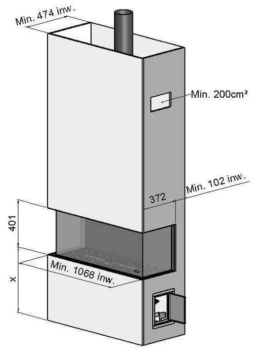
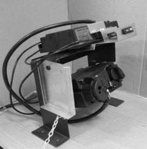
7 1 Dear user Congratulations on purchasing your Faber product! A quality product, which provide you with the warmth and atmosphere for many years. Please read the user manual before using the fire. Should, despite the careful final checks, a malfunction occur, please contact your Faber dealer. Please note: The data of your fire is available in the user manual. 1.1 Introduction Only have the appliance installed by a qualified installer according to the gas safety regulations. Read this installation manual properly. 1.2 Please check including the glass, can be very hot (over 100 C); exceptions to this are the bottom of the fire and the control elements. Do not place any combustible materials within 0.5 m of the radiation area of the fire. Light the fire for the first time and run for several hours on the highest setting, so that the paint can cure. Provide adequate ventilation, so that any fumes can disperse ; we recommend vacating the room during this process Please note Through the natural air circulation of the fire moisture and uncured volatile components from paint, building materials and carpeted floors, etc. are attracted. These parts can settle as soot on cold surfaces. Therefore do not light the fire shortly after installation. Check the fire for transport damage and report any damage immediately to your dealer. 1.3 CE Declaration Glen Dimplex Benelux certifies that this Faber fire complies with the essential requirements of the gas appliances directive. Product: gas room heater Model: Triple Premium L Applicable EC directives: 90/396/EEC Harmonised standards applied: NEN-EN-613 NEN-EN-613/A1 This Declaration is invalid, if without the written permission of Glen Dimplex Benelux: Changes are made to the appliance. The fire is connected to other exhaust materials than specified. 2 Safety instructions The unit must be installed and checked every year according to these instructions and the applicable national and local regulations. Ensure that the data on the type label matches the local gas type and pressure. The settings and the construction of the fire must not be changed! Do not place extra imitation wood or other smouldering material on the burner or in the combustion chamber. The unit is for atmosphere and heating purposes. This means that all surfaces, 3 Installation requirements 3.1 Fire This device can be built into an existing or new chimney. For devices with flexible gas pipes the gas regulator block is mounted on the right side of the fire for transport reason. The gas regulator block with the receiver and the I.T.C. must be placed directly behind a service door. (Fig. 1.5) 3.2 False chimney breast or other structure The False chimney should be of noncombustible material. The space above the fire should always be ventilated using the supplied grids or a similar alternative with minimal free passage of 200cm² per grid. 3.3 Fluepipe and terminal requirements For the supply of the combustion air and the discharge of the combustion gases you should always use the Flue materials specified by Faber. Please note: Only when using these materials can Faber guarantee the safe and proper operation of the appliance. The outside of the concentric flue material can heat up to +/-150 C. Ensure, when penetrating a flammable wall or ceiling, 6 < < < <
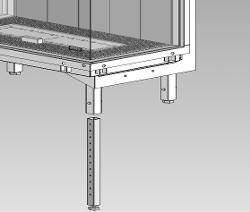
8 construction with proper insulation and protection. And ensure respective distance. Ensure for great discharge lengths that the concentric discharge material is supported every meter, so that the weight of the material is not supported by the fire. It is not permitted to start directly on the device with concentric cut down pipe material. The air supply could then possibly be closed. 3.4 Terminals The combined supply and discharge can be done both via wall or through the roof or through an existing chimney. Please note: Verify if the position of the terminal meets the local regulations regarding ventilation openings. For proper functioning, the air supply and combustion gas discharge are not to be obstructed. The minimum distances are specified in Chapter C 11, Wall terminal. For a facade or wall outlet use a wall terminal. (Fig. 5.0 C 11 ) Depending on the calculation this can be a diameter of 130/200mm or 100/150mm C 31, Roof terminal. For a flat or pits roof outlet use a long roof outlet with a diameter of 100/150mm (Fig. 5 0 C 31 ) C 91, Existing chimney. For an existing chimney use the short chimney outlet with a diameter of 100/150mm (Fig.5.0 C 91 ). In this case the existing chimney acts as air inlet an inserted flexible stainless steel pipe discharges the flue gas. The top and the bottom should be airtight. Depending on the calculated outlet diameter, use a flexible stainless steel tube of Ø 100mm or Ø 130mm with CE marking for 600 C. Please note: The minimum chimney diameter for a 130mm flexible stainless steel pipe must 200 x 200mm. And for a 100mm flexible stainless steel pipe 150x150mm. 4 Preparation and installation instructions 4.1 Gas connection The gas connection must comply with the applicable local standards. We advise using a Ø 15mm gas connection directly from the gas meter to the appliance, with a shutoff valve in the proximity of the appliance, which must always be freely accessible. Position the gas connection so that it is easily accessible at all times for service, and that the burner unit can be disassembled. 4.2 Electrical connection The power supply must comply with the applicable local standards. A 6 Volt adapter is used. For this, a wall socket 230VAC/50Hz must be installed near the fire. 4.3 Preparing the fire Remove the fire from its packaging. Ensure that the gas supply pipes under the appliance are not damaged. Remove frame and glass and take the packaged parts from the fire. Store frame and glass in a safe place. Prepare the gas connection on the regulator 4.4 Positioning the fire Take the installation requirements into account (see Chapter 3) Standing on the floor Place the unit in the right position and set the height with the leg levellers. Height adjustment and levelling of the fire (Fig. 1.4). Rough height adjustment: with the extendable leg, or with the long legs supplied. Fine adjustment: with the adjustable feet Suspended from the wall The appliance can be mounted suspended from the wall with the use of the suspension bracket and the Rawlplugs supplied (Fig.1.3). 7 < < < <
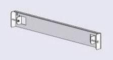
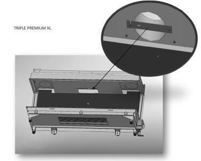
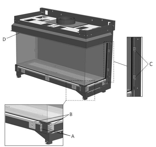
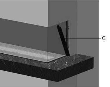
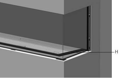
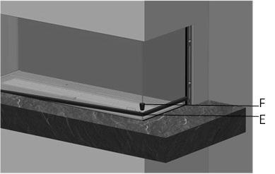
9 These mounting materials are exclusively intended for use on walls constructed of brick or concrete. For walls built of other materials, such as hollow bricks, consult a professional expert. 4.5 Installing the Flue materials When penetrating a wall or ceiling the opening must be at least 5mm larger than the diameter of the discharge material. Horizontal sections should be installed with a slope towards the fire (3 degrees). Build the system from the fire. If this is not possible you can make use of an extendable adapter section. For truing up the exhaust system use the ½ meter pipe, which can be shortened and ensure that the inner pipe is always 2cm longer than the outer pipe. Parts, which are shortened, must be secured with a self-tapping screw Wall and roof terminals can also be cut. Do not insulate but ventilate built-in flue material. (approx. 100cm2). 4.6 Constructing the false chimney If possible, carry out a performance test on the fire before finally finishing the installation Minimum false chimney size and distance to combustible materials Construct the false chimney of non-combustible material in combination with metal profiles or of masonry/concrete blocks. Always use a lintel or reinforcing bars while bricking the outlet. They should not be placed directly on the fire Ventilation The ventilation must comply with the applicable local standards. Correct ventilation prevents a too high temperature of the gas regulator block and its electronics and also limits the temperature of the convection air. Therefore plan for outlet of grills and a ventilating control hatch with a minimum free passage of 200cm 2 per grid or a similar alternative. Place above the grates a screen plate made of noncombustible material. ( Fig. 1.2A) Installation and finishing For installation and finishing the following points are of interest: A = Fixing points (Fig. 2.2). B = Mouldings (Fig. 2.2). C = Spacer (Fig. 2.5) D, F and H (Fig. 2.2, 2.3 and 2.5). Please note: Ensure that the fire is not load-bearing with regard to the false chimney breast. (See the dimensional drawing Chapter 16.1). Pay special attention to the following points: 1. Check during work if the glass can be inserted and removed. 2. Check during work if the strips T (Fig. 3.2) or Q (Fig. 3.3) match Method 1 (Fig. 2.1a) Build the false chimney breast against the fixing points A, the mouldings B and the build-in frame D (Fig. 2.2). The installation must always allow for installing and removing the glass! Take into account the thickness of the finish! Mouldings B has to be in line (F Fig. 2.3) with the top of the glass slot H.(Fig. 2.5) Do not use moulding B as a supporting structure (fig. 2.5) Remove the fixing points (A) on the side wall before the outlet wall is finally finished! (Fig. 2.4) Method 2 (Fig. 2.1b) Process see Chapter Method 3 (Fig. 2.1c) Remove the moulding B (Fig. 2.2). To ensure the air-tightness of the unit the screws must be replaced. The base X (Fig. 2.5) must be 2mm clear of the spacer C (Fig. 2.5) and 4mm above the glass slot H of the unit (Fig. 2.5). This will allow the Strip Q (Fig. 3.3) to be on the same level as the base Mounting the Solid cover strips (Fig. 3.1, 3.2 and 3.3) First, place the bottom strip (T or Q) Then place the left and right strips (S) (these are fixed by the adjustable magnetic snappers) 8 < < < <
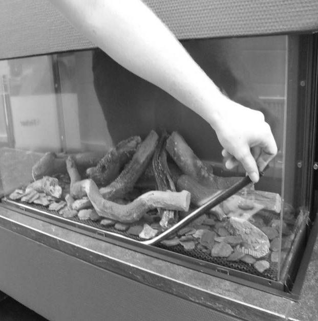
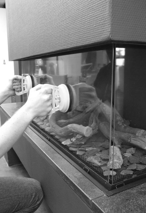
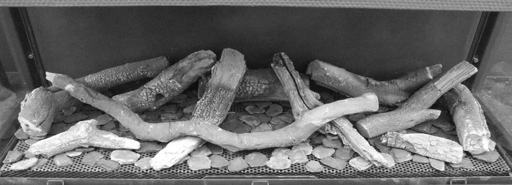
10 Remove the bottom strip (Q) using the supplied magnetic knob (R, Fig. 3.3). 5 Removing the glass 5.1 removing the front glass Remove the solid covers trips see Chapter Place the suction cups on the glass. Draw the sealing cord from the slot. (Fig.4.1). Slide the glass to the top so that the bottom is released from the slot. Now pull the glass out and gradually down. (Fig. 4.2). 5.2 removing the glass from the side It is not necessary to take out the glass on the side for placing the log set or for maintenance. First remove the front glass. Remove the log set, bottom plate and burner. (Fig. 4.3) Place the suction cups on the glass Remove the sealing cord from the slot. Remove the top of the glass gradually forward and up from the fire (Fig.4.4) Please note Replace the glass in reverse order. Clean all fingerprints from the glass, otherwise they will burn in once the fire is used. 6 Placing the decoration material It is not permitted to use other or to add more material in the combustion chamber. Keep the pilot light always free of decoration material! Do not place all decoration material at one time on the burner; the fabric parts can block it. 6.1 Log set Place some of the chips on the burner and on the bottom. Place the logs as specified. (Fig.5.1 or the included log set card) Divide the rest of the chips on the burner and on the bottom. Prevent a thick layer on the burner; this adversely affects the flame pattern. 6.2 Glow wire The glow wire gives a decorative glow effect. Pull the wool well apart and place tufts in different places on the burner. Please note: Do not use the glow wire near the pilot flame! This can cause a short circuit in the ignition system! 6.3 Pebbles or Grey stone Place the pebbles or grey stones on the burner and on the bottom. (Fig. 5.2 and 5.3 or the included log set card). Prevent a double layer; this adversely affects the flame pattern. Replace the glass and check the flame pattern. Start the fire as described in the user manual. Check if the flame distribution is good. Move the chips if necessary, until a good flame distribution is achieved. 7 Checking the installation 7.1 Checking the main burner ignition, pilot flame Ignite the fire as described in the user manual. Check that the pilot flame is well above the main burner and not covered by chips. Check the ignition of the main burner on full and small setting. (ignition must be smooth and quiet). 7.2 Checking for gas leaks Check with a gas leak finder or spray all connections and pipes for gas leakage. 7.3 Checking the burner pressure and primary pressure Check that the burner pressure and primary pressure match the information listed in the manual, Chapter 14 Technical specifications. Measuring the primary pressure: Close the shutoff valve. Turn measuring nipple B (Fig. 1.6) some turns open and connect a measuring hose to the gas regulator. 9 < < < <
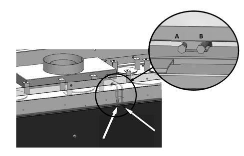
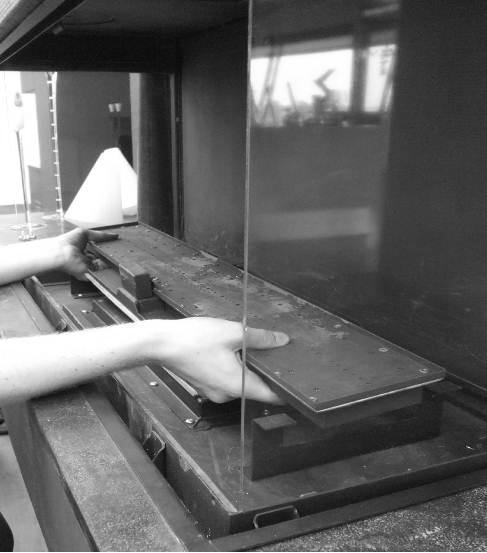
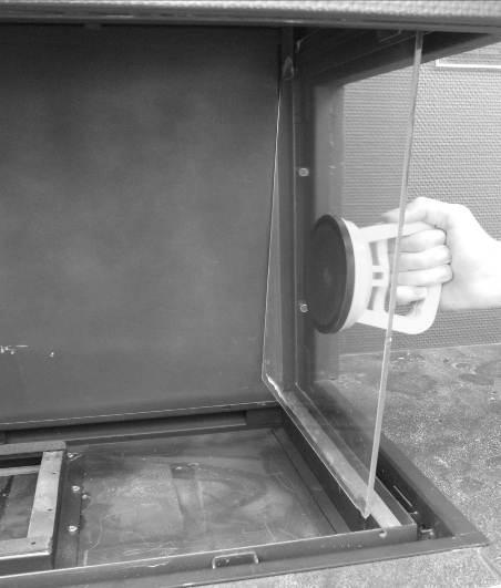
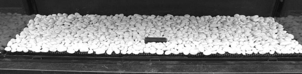
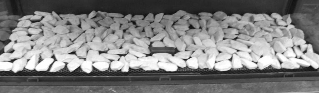
11 Take this measurement at highest setting of the fire and when the fire is set to pilot light. Do not connect the unit if the pressure is too high. Measuring the burner pressure: Check the burner pressure only with proper primary pressure. Turn measuring nipple A (Fig. 1.6) some turns open and connect a measuring hose to the gas regulator. The pressure must correspond to the value indicated in the technical specifications of this manual. In case of deviation contact the manufacturer. Please note: Close all pressure measuring nipples and check for gas leakage. 7.4 Checking the flame image Let the fire burn for at least 20 minutes at highest setting and check the flame for: 1. Flame distribution 2. Colour of the flames If one or both points are not acceptable then check: The log set layout and/or the amount of chips on the burner. The pipe connections for leaks (in case of blue flames). Whether the correct Restrictor is fitted. The outlet. o Wall terminal right side up o Roof terminal on the right position o If the maximum horizontal flue lengths is not exceeded. 7.5 Flue gas analyzer If you are in possession of a CO/CO2 flue gas analyzer, then it is possible to check the supply air and the combustion gases. There are two measuring pipes at the front of the fire between the mounting frame and the glass (Fig. 1.7 A and B). The ratio CO2 and CO must not be greater than 1:100 Example: CO2 is 4% and CO is 400ppm, measured at the highest point If the ratio is greater than 1:100 or exhaust gases are measured in the supply air, then also check above points. 8 Instructions for client Recommend that the unit should be checked annually by a qualified specialist to ensure the safe use and to guarantee a long service life. Give advice and instructions on care and cleaning of the glass. Highlight the danger of burnt-in fingerprints. Instruct the customer on the operation of the unit and the remote control, including replacing the batteries and setting the receiver. Handover to customer: o Installation instructions o User manual o ITC operating instructions o Log set instruction card o Suction Cups o Magnetic snapper 9 Annual maintenance 9.1 Checking and cleaning: Check and clean if necessary after verification: o The pilot light o The burner; for LPG flat burner the ceramic burner top. o The combustion chamber o The glass o The ceramic logs for breakages. o The flue system. Replace, if necessary: o Chips/Embers/ Glow wire 9.2 Cleaning the glass Most deposits can be removed with a dry cloth. Clean the glass with a ceramic hob cleaner. Please note: Avoid fingerprints on the glass. These are no longer removable after they are burnt in! Now carry out the checks described in Chapter 7 Checking after installation. 10 < < < <
12 10 Conversion to other gas type The conversion to a different gas type may only be performed by a qualified installer/dealer Conversion from natural gas to propane (or vice versa) This can only be done by replacing the burner. To do so, please contact your dealer. Specify with your order always the type and serial number of the device. Total Vertical Height (TVH) TVH is the difference in height measured from the top of the fire to the outlet; it can be measured or determined from the building plan. For clarification see the TVH indication in the drawings. (Fig. 12.1, 12.2 and 12.3: TVH) Total Horizontal Length (THL) THL is the Total Horizontal Length and consists of elbows and pipes which are entirely in the horizontal plane. Elbows I, K and Q and the elements H, J, L, M, P and R (Fig and 12.3). Horizontal length The horizontal length consists of the elements H, J, L, M, P and R (Fig end 12.3). Elbows 90 in the horizontal plane Horizontal bends are bends which are entirely in the horizontal plane (Fig. 12.1, 12.2 and 12.3 I, K and Q). 11 Flue calculation A simple way to calculate whether the exhaust configuration is possible in combination with your fire, use the free Faber Flue App and download from: INTERNET: BlackBerry, Android, PC (with Google Chrome browser) APP store: iphone, ipad and Mac. Google Play: Android smartphones and Android tablets. Alternatively use the exhaust calculation table. (see chapter 13). The alternatives of outlet lengths and any restrictors are set out in the restrictor table. In the table we work with Start Length (STL) Total Vertical Height (TVH) and Total Horizontal Length (THL). Start Length (STL) This is the first part that is placed on the fire and represents a certain value (Fig. 12.1, 12.2 and 12.3 A, N, F). This value is in the top row of the table (see table). Bends 45 or 30 in the horizontal plane Horizontal bends are bends which are entirely in the horizontal plane Bends Elbows 90 vertical to horizontal plane These are 90 elbows, which proceed from horizontal to vertical (Fig and 12.3 G, O and S) Bends 45 or 30 vertical to horizontal plane These are 30 or 45 bends with a vertical offset of less than 45 (Fig.12.1 B and D). Pipes under a tilt angle: These are pipes which are vertically ascending at an angle of 30 or 45. (Fig C). Fill in only in combination with at least 2 x 30 or 45 bends in the vertical part. Table: See the table at the right vertical (TVH) and horizontal length (THL). For x and if the values are outside the table, then the combination is not allowed. Only then adjust the TVH or THL. If a value is indicated, check that the calculated STL value is not lower than indicated in the table. In this case STL must be adjusted. The found value indicates the width of the restrictor ( 0 means no restrictor). Standard is a restrictor of 30mm installed. (Fig.1.8). 11 < < < <
13 11.1 Table for pipe diameter 150/100mm STL TVH Startlength (STL) Vertical (TVH) and Horizontal (THL) STL 0, TVH THL 0 x x x x x x x x x x x 0,5 x x x x x x x x x x x x x x x x x x x x 1,5 0,2 0,2 x x x x x x x x x 2 0,2 30,2 0,2 x x x x x x x x 3 30,2 40,2 0,2 x x x x x x x x 4 40,2 40,2 30,2 0,2 x x x x x x x 5 45,2 40,2 40,2 30,2 x x x x x x x 6 45,2 45,2 40,2 40,2 x x x x x x x 7 50,2 45,2 45,2 40,2 x x x x x x x 8 50,2 50,2 45,2 45,2 x x x x x x x 9 50,2 50,2 50,2 45,2 x x x x x x x 10 60,2 50,2 50,2 50,2 x x x x x x x 11 60,2 60,2 50,2 50,2 x x x x x x x 12 70,2 70,2 60,2 50,2 x x x x x x x 13 70,2 70,2 70,2 60,2 x x x x x x x 14 80,2 70,2 70,2 70,2 x x x x x x x 15 80,2 80,2 80,2 70,2 x x x x x x x 16 80,2 80,2 80,2 80,2 x x x x x x x 17 80,2 80,2 80,2 80,2 x x x x x x x 18 80,2 80,2 80,2 80,2 x x x x x x x 19 80,2 80,2 80,2 80,2 x x x x x x x 20 80,2 80,2 80,2 80,2 x x x x x x x 21 80,2 80,2 80,2 80,2 x x x x x x x 22 80,2 80,2 80,2 80,2 x x x x x x x 23 80,2 80,2 80,2 80,2 x x x x x x x 24 80,2 80,2 80,2 80,2 x x x x x x x 25 80,2 80,2 80,2 80,2 x x x x x x x 26 80,2 80,2 80,2 80,2 x x x x x x x 27 80,2 80,2 80,2 80,2 x x x x x x x 28 80,2 80,2 80,2 x x x x x x x x 29 80,2 80,2 x x x x x x x x x x x x x x x x x x x THL 12 < < < <
14 11.2 Table for pipediameter 130/200mm STL TVH Startlength (STL) Vertical (TVH) and Horizontal (THL) STL 0,1 0,2 0,5 0, TVH THL 0 x x x x x x x x x x x 0,5 x 30 x x x x x x x x x x x 1,5 40,4 50,4 40,4 30,4 0,4 0,4 0,4 0,4 0,4 x x 2 50,4 60,4 50,4 40,4 30,4 0,4 0,4 0,4 0,4 x x 3 60,4 65,4 60,4 50,4 40,4 30,4 0,4 0,4 0,4 x x 4 65,4 70,4 65,4 60,4 50,4 40,4 30,4 0,4 0,4 x x 5 70,4 70,4 70,4 65,4 60,4 50,4 40,4 30,4 0,4 x x 6 70,4 70,4 70,4 70,4 65,4 60,4 50,4 40,4 30,4 x x 7 70,4 80,4 70,4 70,4 70,4 65,4 60,4 50,4 40,4 x x 8 80,4 80,4 80,4 70,4 70,4 70,4 65,4 60,4 50,4 x x 9 80,4 80,4 80,4 80,4 70,4 70,4 70,4 65,4 60,4 x x 10 80,4 80,4 80,4 80,4 80,4 70,4 70,4 70,4 65,4 x x 11 80,4 80,4 80,4 80,4 80,4 80,4 70,4 70,4 70,4 x x 12 80,4 80,4 80,4 80,4 80,4 80,4 80,4 70,4 70,4 x x 13 85,4 80,4 80,4 80,4 80,4 80,4 80,4 80,4 70,4 x x 14 85,4 85,4 80,4 80,4 80,4 80,4 80,4 80,4 80,4 x x 15 85,4 85,4 85,4 80,4 80,4 80,4 80,4 80,4 80,4 x x 16 85,4 85,4 85,4 85,4 80,4 80,4 80,4 80,4 80,4 x x 17 85,4 85,4 85,4 85,4 85,4 80,4 80,4 80,4 80,4 x x 18 85,4 85,4 85,4 85,4 85,4 80,4 80,4 80,4 80,4 x x 19 85,4 85,4 85,4 85,4 85,4 85,4 80,4 80,4 80,4 x x 20 85,4 85,4 85,4 85,4 85,4 85,4 85,4 80,4 80,4 x x 21 85,4 85,4 85,4 85,4 85,4 85,4 85,4 85,4 80,4 x x 22 85,4 85,4 85,4 85,4 85,4 85,4 85,4 85,4 85,4 x x 23 85,4 85,4 85,4 85,4 85,4 85,4 85,4 85,4 x x x 24 85,4 85,4 85,4 85,4 85,4 85,4 85,4 x x x x 25 85,4 85,4 85,4 85,4 85,4 85,4 x x x x x 26 85,4 85,4 85,4 85,4 85,4 x x x x x x 27 85,4 85,4 85,4 85,4 x x x x x x x 28 85,4 85,4 85,4 x x x x x x x x 29 85,4 85,4 x x x x x x x x x 30 85,4 x x x x x x x x x x THL 13 < < < <

15 12 Example fig fig.12.2 fig < < < <

16 13 Calculation sheet 15 < < < <

17 16 < < < <
18 14 Technical data Gascat. II2H3+ II2H3+ II2H3+ Type appliance C11 C31 C11 C31 C11 C31 Reference gas G20 G30 G31 Input Nett kw ,5 Efficiency class NOx class inlet-pressure mbar Gas rate at 15ºC and 1013 mbar l/h Gas rate at 15ºC and 1013 mbar gr/h Burner pressure at full mark mbar Injector main burner mm 2x St510 (7x0,83) 2x St180 (7x0,5) 2x St180 (7x0,5) Reduced input restraint mm 2,10 1,60 1,60 Pilot assembly SIT145 SIT145 SIT145 Code Nr.36 Nr.23 Nr.23 Diameter inlet / outlet mm 200/ / /130 Gas control valve GV60 GV60 GV60 Gas connection 3/8 3/8 3/8 Electrical connection V Batteries receiver V 4x AA (1,5V) 4x AA (1,5V) 4x AA (1,5V) Batteries sender V < < < <
19 15 Terminal position Please note: These rules apply only for the proper functioning of the unit, for ventilation and environmental protection you need to comply with the applicable rules as defined in the building regulations. Short roof terminal Only for existing Chimney connection Extension pipe over roof Location Distance mm D Under a gutter 500 E Under a roof edge 500 F Under a carport or balcony 500 G Vertical downpipe 300 H Inside and outside corners 500 J From wall surface to a wall outlet 1000 K Two gable outlets against over each other 1000 L Distance between two roof outlets 450 M Two roof outlets above each other on a pitched roof 1000 N Two gable outlets next to each other < < < <
20 16 Dimensional drawings 16.1 Triple Premium L 19 < < < <
21 16.2 Ventilation grid and control door 20 < < < <
22 21 < < < <
23 22 < < < <


24
SERVICE MANUAL SALAMANDER BROILERS RADIANT AND INFRARED 36RB 36IRB VULCAN C36RB C36IRB WOLF
 SERVICE MANUAL SALAMANDER BROILERS RADIANT AND INFRARED VULCAN 36RB 36IRB WOLF C36RB C36IRB This Manual is prepared for the use of trained Vulcan Service Technicians and should not be used by those not
ACCESSORY KIT INSTALLATION INSTRUCTIONS
 ACCESSORY KIT INSTALLATION INSTRUCTIONS 1NP0680 - PROPANE CONVERSION FOR USE WITH MODELS: PM8, PC8, PM9, PC9, FL9M, FL9C, FC9M, FC9C This conversion kit is to be installed by a qualified service agency
Standard Gas Countertop Griddle
 Standard Gas Countertop Griddle This manual contains important information regarding your unit. Please read the manual thoroughly prior to equipment set-up, operation and maintenance. Failure to comply
USER S INFORMATION MANUAL
 USER S INFORMATION MANUAL UPFLOW, DOWNFLOW, UPFLOW/HORIZONTAL & HORIZONTAL ONLY INDUCED DRAFT GAS FURNACES Recognize this symbol as an indication of Important Safety Information If the information in this
Owner s Manual Installation and Operation
 Owner s Manual Installation and Operation Models: RED40-N-AU RED40ST-N-AU Ref No: GMK10107 AS4553:2008 Important operating and maintenance instructions included. NOTICE DO NOT DISCARD THIS MANUAL Read,
ROBERT H. PETERSON CO. AUTOMATIC REMOTE LIGHTING SAFETY PILOT SYSTEM WITH VARIABLE FLAME-HEIGHT REMOTE FOR NATURAL OR PROPANE GAS. Model APK-17(M)(P)
(P)") ROBERT H. PETERSON CO. Owner s Manual AUTOMATIC REMOTE LIGHTING SAFETY PILOT SYSTEM WITH VARIABLE FLAME-HEIGHT REMOTE FOR NATURAL OR PROPANE GAS FEATURES: CONTROL OPERATED ON/OFF VARIABLE FLAME-HEIGHT
ROBERT H. PETERSON CO. Owner s Manual AUTOMATIC REMOTE LIGHTING SAFETY PILOT SYSTEM WITH VARIABLE FLAME-HEIGHT REMOTE FOR NATURAL OR PROPANE GAS FEATURES: CONTROL OPERATED ON/OFF VARIABLE FLAME-HEIGHT
Gas Countertop Hot Plates
 Gas Countertop Hot Plates This manual contains important information regarding your Patriot unit. Please read the manual thoroughly prior to equipment set-up, operation and maintenance. Failure to comply
INSTRUCTION MANUAL. Gas Salamander
 INSTRUCTION MANUAL Gas Salamander This manual contains important information regarding your unit. Please read this manual thoroughly prior to equipment set-up, operation and maintenance. Failure to comply
13kW Patio Heater. Assembly & User Instructions
 13kW Patio Heater Assembly & User Instructions GUARANTEE The Memphis patio heater is made by Universal Innovations to an exacting quality standard and is covered by the following guarantee: THIS PRODUCT
WARNING: Gas Conversion Kit Instructions Applies to: Model UDAP, UDAS, UDBP, and UDBS Unit Heaters. General and Warnings FOR YOUR SAFETY
 Form CP-UD-GC Obsoletes I-UD-GC (Version E) Gas Conversion Kit Instructions Applies to: Model UDAP, UDAS, UDBP, and UDBS Unit Heaters General and Warnings All gas conversion must be done by a qualified
Dual Solenoid Gas Valve Installation
 Installation IMPORTANT: These instructions are intended as a guide for qualified personnel installing or servicing FLYNN Gas Products. Carefully follow all instructions in this bulletin and all instructions
Propane Conversion Kit Instruction
 Propane Conversion Kit Instruction Condensing gas boiler Required Input Rates GB142-24 84,800 btu/hr GB142-30 106,000 btu/hr GB142-45 160,900 btu/hr GB142-60 214,800 btu/hr This kit and instructions are
CRAFTSMAN EXAMINATION, NOVEMBER 2007 GASFITTING ANSWER SCHEDULE
 No. 9196 CRAFTSMAN EXAMINATION, NOVEMBER 2007 GASFITTING ANSWER SCHEDULE Plumbers, Gasfitters and Drainlayers Board, 2007. All rights reserved. No part of this publication may be reproduced by any means
GM-7000 Series CE Approved Gas Control Valve
 Installation Instructions GM-7000 Issue Date November 9, 2012 GM-7000 Series CE Approved Gas Control Valve Installation IMPORTANT: These instructions are intended as a guide for qualified personnel installing
Declaration of Performance (DOP)
") Declaration of (DOP) No. 9174 061 DOP 2017-09-22 1. Unique identification code of the product-type: Multi-wall chimney system type DW-KL-ECO 2.0 according to 2. Type, batch or serial number or any other
Declaration of (DOP) No. 9174 061 DOP 2017-09-22 1. Unique identification code of the product-type: Multi-wall chimney system type DW-KL-ECO 2.0 according to 2. Type, batch or serial number or any other
GAS SUPPLY APPLICATION GUIDE
 GAS SUPPLY APPLICATION GUIDE Natural Gas or Propane Modulating & Condensing Boilers and Water Heaters This document applies to the following models: Boilers AM 399B AM 500B AM 750B AM 1000B Gas-Fired Boilers
Propane Conversion Kit Instruction
 Propane Conversion Kit Instruction Condensing gas boiler Required Input Rates Logamax plus GB62-80 kw 270,000 btu/hr Logamax plus GB62-00 kw 35,000 btu/hr This kit and instructions are for converting the
Propane Conversion Kit Instruction
 Propane Conversion Kit Instruction Condensing gas boiler Required Input Rates GB42-24 84,800 btu/hr Tab. GB42-30 06,000 btu/hr GB42-45 49,000 btu/hr GB42-60 24,800 btu/hr This kit and instructions are
G196 Series BASOTROL Redundant Combination Gas Valve with Manual Shutoff Valve
 Installation Instructions Issue Date August 19, 2008 G196 Series BASOTROL Redundant Combination Gas Valve with Manual Shutoff Valve Application The G196 valves are suitable for use with natural gas, Liquefied
G196 Series BASOTROL Redundant Combination Gas Valve with Manual Shutoff Valve
 Installation Instructions Issue Date March 13, 2013 G196 Series BASOTROL Redundant Combination Gas Valve with Manual Shutoff Valve Application The G196 valves are suitable for use with natural gas, Liquefied
INSTALLATION AND OPERATING INSTRUCTIONS BIG TEX VENTED GAS LOGS
 INSTALLER! PLEASE LEAVE WITH HOMEOWNER INSTALLATION AND OPERATING INSTRUCTIONS BIG TEX VENTED GAS LOGS by Please Note: It is important that you read instructions before installing or operating gas logs
ACCESSORY KIT INSTALLATION INSTRUCTIONS
 ACCESSORY KIT INSTALLATION INSTRUCTIONS PROPANE CONVERSION - INDUCED COMBUSTION FURNACES 1NP0501 FOR USE WITH 95% MODELS: TG9S, GG9S (130,000 BTU ONLY) FOR USE WITH 80% MODELS: TG(8,L)S, GG(8,L)S (130,000
GM Series Dual-Block Multi-Function Gas Control Valves
 Installation Sheets Manual 121 Gas Combustion Combination Controls and Systems Section G Technical Bulletin GM Issue Date 0297 GM Series Dual-Block Multi-Function Gas Control Valves Figure 1: GM Series
BGA158 Series CE Approved Class B Shutoff Gas Valve
 Installation Instructions BGA158 Issue Date March 22, 2016 BGA158 Series CE Approved Class B Shutoff Gas Valve Applications The BGA158 Series shutoff gas valve is an electrically operated shutoff valve
36H SERIES Combination Gas Valve
 FAILURE TO READ AND FOLLOW ALL INSTRUCTIONS CAREFULLY BEFORE INSTALLING OR OPERATING THIS CONTROL COULD CAUSE PERSONAL INJURY AND/OR PROPERTY DAMAGE. DESCRIPTION The 36H series combination gas valve is
WP2 Fire test for toxicity of fire effluents
 Pagina 3 di 89 TRA SFEU VTT 22.6.2009 v.2 WP2 Fire test for toxicity of fire effluents Task 2.1.2 Development of small-scale test method for fire effluents Step 1: Use of modeling Plans according to DoW:
VULCAN GAS SALAMANDER MODEL SG-G
 VULCAN GAS SALAMANDER MODEL SG-G Index: General Data 2 Owners Responsibility 3 Authorised Vulcan Catering Equipment Branches And Dealers 3 Parts Ordering / Service Information 4 Prior to Installation Of
BP48-1 AND SSP48-1 IN-GROUND POST INSTALLATION INSTRUCTIONS
 BP48-1 AND SSP48-1 IN-GROUND POST INSTALLATION INSTRUCTIONS WARNING: THIS IN-GROUND POST IS NOT DESIGNED FOR USE WITH AN LP GAS CYLINDER. WARNING: SEE YOUR GRILL OWNER S MANUAL FOR PROPER LOCATION, MINIMUM
BGA158 Series CE Approved Class A Shutoff Gas Valve
 Installation Instructions BGA158 Issue Date August 24, 2011 BGA158 Series CE Approved Class A Shutoff Gas Valve Applications The BGA158 Series shutoff gas valve is an electrically operated gas valve that
Intro: by firechim on October 3, 2013
 by firechim on October 3, 2013 Intro: Step 1: Guide for installing chimney liners with a tee connection This guide is to give you step by step instructions to install a chimney liner that utilizes a tee
Operator Manual Gas Griddle / Cheesemelter
 Operator Manual Gas Griddle / Cheesemelter HDB2031 & HDB2042 Model: HDB2042 Table of Contents Safety Information...2 Unpacking...3 Installation...3 Lighting Instructions...3 Preparing Griddle...4 Operation...4
The conversion of new certified central heating gas appliances must conform to directions outlined in this instruction.
 ACCESSORY KIT INSTALLATION INSTRUCTIONS HIGH ALTITUDE APPLICATION CONVERSION MID-EFFICIENCY SINGLE-STAGE INDUCED COMBUSTION FURNACES MODELS: P*HU/G8T-UH/L8T-UH/FL8 UPFLOW / HORIZONTAL P*DN/G8T-DN/L8T-DN
INSTALLATION GUIDE Gas Rangetops
 INSTALLATION GUIDE Gas Rangetops Contents Wolf Gas Rangetops........................... 3 Safety Instructions............................ 4 Gas Rangetop Specifications.................... 5 Gas Rangetop
G96 Series BASOTROL Dual Operator Valve
 Installation Instructions 9. Issue Date February 22, 2013 G96 Series BASOTROL Dual Operator Valve Applications The G96 valves are combination, dual operator, automatic valves available with or without
GS-20/25 and GS-40/45 Series Single-block Multi-function Gas Control Valves
 Installation Sheets Manual 121 Gas Combustion Combination Controls and Systems Section G Technical Bulletin GS-20/25 GS-40/45 Issue Date 1298 GS-20/25 and GS-40/45 Series Single-block Multi-function Gas
User, Installation, Servicing and Conversion Instructions. Opus 700 Gas Chargrills OG7401, OG7402, OG7403 & OG7404
 User, Installation, Servicing and Conversion Instructions Opus 700 Gas Chargrills OG7401, OG7402, OG7403 & OG7404 Please make a note of your product details for future use: Date Purchased: Model Number:
ACCESSORY KIT INSTALLATION MANUAL
 ACCESSORY KIT INSTALLATION MANUAL LP (PROPANE) CONVERSION KIT 1NP0366 FOR USE WITH MODELS: G8C & GF8 This conversion kit shall be installed by a qualified service agency in accordance with these instructions
OPERATING INSTRUCTIONS
 0/05 OPERATING INSTRUCTIONS for gas pressure regulators PN0 with integrated slam shut valve (SSV) and integrated limited capacity safety relief valve (RV) MR 25 F0, MR 25 SF0 p e 20 kpa - 0 MPa (0,2-0
VR46.5V(A)/VR86.5V(A) SERIES
/VR86.5V(A) SERIES") VR46.5V(A)/VR86.5V(A) SERIES COMACT COMBINATION GAS CONTROS WITH INTEGRATED 1:1 GAS/AIR REGUATOR FOR AUTOMATIC IGNITION SYSTEMS SECIFICATIONS INSTRUCTION SHEET Subject to change without notice. rinted
VR46.5V(A)/VR86.5V(A) SERIES COMACT COMBINATION GAS CONTROS WITH INTEGRATED 1:1 GAS/AIR REGUATOR FOR AUTOMATIC IGNITION SYSTEMS SECIFICATIONS INSTRUCTION SHEET Subject to change without notice. rinted
Gas Countertop Griddle
 Gas Countertop Griddle This manual contains important information regarding your purchased equipment. Please read the manual thoroughly prior to equipment set-up, operation and maintenance. Failure to
UL Listed GM-20/25 and GM-40/45 Series Dual-block Multi-function Gas Control Valves
 Installation Sheets Manual 121 Gas Combustion Combination Controls and Systems Section G Technical Bulletin GM-20/25 GM-40/45 Issue Date 1298 UL Listed GM-20/25 and GM-40/45 Series Dual-block Multi-function
BGA158, BGA171 and BGA110 Series Shutoff Gas Valve
 Installation Instructions BGA Series Issue Date October 3, 2017 BGA158, BGA171 and BGA110 Series Shutoff Gas Valve Applications The BGA Series shutoff gas valve is an electrically operated gas valve that
Installation and operation manual SUNWOOD MARINO LPG
 Installation and operation manual SUNWOOD MARINO Version: Natural Gas LPG Specifications Manufacturer Sunderman Openhaarden V.O.F. / Sunwood Contact details Christiaan Huygensstraat 10 2665 KX Bleiswijk
GAS BBQ 4 burner. instructions for. model no: BBQ10
 instructions for GAS BBQ 4 burner model no: BBQ10 Thank you for purchasing a Sealey product. Manufactured to a high standard, this product will, if used according to these instructions, and properly maintained,
GEN-1e CO2 Generator OVERVIEW INSTALLATION PROPANE GENERATORS ONLY NATURAL GAS GENERATORS ONLY
 GEN-1e CO2 Generator Custom Automated Products offers economical and safe carbon dioxide generators. They produce CO2 by burning either propane or natural gas. We have designed our CO2 generator to allow
36E DSI, HSI & Proven Pilot Two-Stage Combination Gas Valve INSTALLATION INSTRUCTIONS
 INLET PRESS TAP WTE-RODGERS 36E96-314 DSI, HSI & Proven Pilot Two-Stage Combination Gas Valve INSTALLATION INSTRUCTIONS Operator: Save these instructions for future use! FAILURE TO READ AND FOLLOW ALL
Robert H. Peterson Company
 Robert H. Peterson Company LOW PROFILE SAFETY PILOT KIT For Natural or Propane Gas Owner s Manual INSTALLER: Please leave these instructions with the consumer. CONSUMER: Please retain for future reference.
G92 Series BASOTROL Automatic Pilot Gas Valve
 Installation Instructions Issue Date September 17, 2008 G92 Series BASOTROL Automatic Pilot Gas Valve Installation IMPORTANT: Only qualified personnel should install or service BASO Gas Products. These
REGISTRATION EXAMINATION, NOVEMBER 2017 TRADESMAN GASFITTER QUESTION AND ANSWER BOOKLET. Time allowed THREE hours
 Affix label with Candidate Code Number here. If no label, enter candidate Number if known No. 99 REGISTRATION EXAMINATION, NOVEMBER 07 TRADESMAN GASFITTER INSTRUCTIONS QUESTION AND ANSWER BOOKLET Time
INSTALLATION, OPERATION, SERVICE & PARTS MANUAL FOR STOCK POT RANGE MODELS VSP100, VSP200 & VSP300
 INSTALLATION, OPERATION, SERVICE & PARTS MANUAL FOR STOCK POT RANGE MODELS VSP100, VSP200 & VSP300 MODEL VSP100 VULCAN-HART COMPANY, P.O. BOX 696, LOUISVILLE, KY 40201-0696, TEL. (502) 778-2791 FORM 30780
Natural Gas Conversion Kit
 SERIAL #: Attention: Centro recommends that a qualified gas technician perform the gas supply conversion and orifice replacement for this BBQ model. Natural Gas Conversion Kit F O R U S E W I T H M O D
TANDEM MODULATOR FOR OUTLET GAS FLOW: STEPPED (836 TANDEM) - CONTINUOUS (837 TANDEM) SERVO-CONTROLLED PRESSURE REGULATOR
 - CONTINUOUS (837 TANDEM) SERVO-CONTROLLED PRESSURE REGULATOR") SIT Group 836-837 TANDEM MULTIFUNCTIONAL GAS CONTROL MODULATOR FOR OUTLET GAS FLOW: STEPPED (836 TANDEM) - CONTINUOUS (837 TANDEM) SERVO-CONTROLLED PRESSURE REGULATOR ALL ADJUSTMENTS ACCESSIBLE FROM ABOVE
SIT Group 836-837 TANDEM MULTIFUNCTIONAL GAS CONTROL MODULATOR FOR OUTLET GAS FLOW: STEPPED (836 TANDEM) - CONTINUOUS (837 TANDEM) SERVO-CONTROLLED PRESSURE REGULATOR ALL ADJUSTMENTS ACCESSIBLE FROM ABOVE
BGC258 Series BASOTROL Gas Valve
 Installation Instructions BGC258 Issue Date September 6, 2017 BGC258 Series BASOTROL Gas Valve Installation IMPORTANT: These instructions are intended as a guide for qualified personnel installing or servicing
FIREPLACE INSTALLATION
 CHECK GAS TYPE Use proper gas type for fireplace unit you are installing. If your gas supply is not correct, do not install fireplace. See retailer where you purchased fireplace for proper fireplace according
USE AND ASSEMBLY INSTRUCTIONS
 USE AND ASSEMBLY INSTRUCTIONS Model: HSQ-A213S; HSQ-B213S; HSQ-A214S; HSQ-B214S; HSQ-A215S; HSQ-B215S; HSQ-A216S; HSQ-B216S HSQ-A213S HSQ-A214S HSQ-A215S HSQ-A216S FOR OUTDOOR USE ONLY PLEASE READ INSTRUCTIONS
Propane Conversion Kit Instructions
 604 8 0/ US/CA For heating engineers Propane Conversion Kit Instructions Logano G4 X gas-fired boiler This conversion kit and the accompanying instructions are for conversion of G4 X gas-fired boilers
36C/36D HSI, DSI Proven Pilot Gas Valves INSTALLATION INSTRUCTIONS
 36C/36D HSI, DSI Proven Pilot Gas Valves INSTALLATION INSTRUCTIONS Operator: Save these instructions for future use! FAILURE TO READ AND FOLLOW ALL INSTRUCTIONS CAREFULLY BEFORE INSTALLING OR OPERATING
36E DSI and HSI Two-Stage Combination Gas Valve INSTALLATION INSTRUCTIONS
 INLET PRESS TAP WTE-RODGERS 36E54-214 DSI and HSI Two-Stage Combination Gas Valve INSTALLATION INSTRUCTIONS Operator: Save these instructions for future use! FAILURE TO READ AND FOLLOW ALL INSTRUCTIONS
GAS CONVERSION KIT Installation Instructions Range/Rangetop
 GAS CONVERSION KIT Installation Instructions Range/Rangetop FOR SERVICE PERSONNEL ONLY IMPORTANT - READ ALL INSTRUCTIONS BEFORE YOU BEGIN THE INSTRUCTIONS HEREIN MUST ONLY BE PERFORMED BY A QUALIFIED SERVICE
Installation Instructions
 48011HW NATURAL GAS TO PROPANE CONVERSION KIT 58HDX, 359AAV, PG9YAB, PG9YAA Installation Instructions SAFETY REQUIREMENTS Installing and servicing heating equipment can be hazardous due to gas and electrical
Operator: Save these instructions for future use!
 WHITE-RODGERS Type 36C67 Combination (24 Volt Models) INSTALLATION INSTRUCTIONS Operator: Save these instructions for future use! FAILURE TO READ AND FOLLOW ALL INSTRUCTIONS CAREFULLY BEFORE INSTALLING
Sample Concentrator SBH CONC/1 Instructions for use
 Sample Concentrator SBH CONC/1 Instructions for use Thank you for purchasing this piece of Barloworld Scientific equipment. To get the best performance from the equipment, and for your own safety, please
GasBloc Multifunctional gas control Combined regulator and safety shut-off valves single-stage atmospheric operating mode GB-(LEP) 057 D01
 057 D01") Gasloc Multifunctional gas control Combined regulator and safety shut-off valves single-stage atmospheric operating mode G-(LEP) 057 D01 3.10 Printed in Germany Edition 05.11 Nr. 249 584 1 6 Technical
Gasloc Multifunctional gas control Combined regulator and safety shut-off valves single-stage atmospheric operating mode G-(LEP) 057 D01 3.10 Printed in Germany Edition 05.11 Nr. 249 584 1 6 Technical
Old documentation - Only for your information! Product is not available any more!
 Gasloc Multifunctional gas control Combined regulator and safety shut-off valves single-stage atmospheric operating mode G-(LEP) 057 D01 3.10 Technical description Multifunctional gas control valve as
INSTRUCTIONS FOR CONVERTING CONDENSING GAS MOBILE HOME FURNACES MODEL SERIES: CMA3*, CMC1*, VMA3*, VMC1*
 INSTRUCTIONS FOR CONVERTING CONDENSING GAS MOBILE HOME FURNACES MODEL SERIES: CMA3*, CMC1*, VMA3*, VMC1* THIS KIT CONTAINS: AOPS7741 (NATURAL TO PROPANE CONVERSION PARTS FOR MODEL SIZE, 50) AOPS7742(NATURAL
GV Standard X-Vent. Setup, Commissioning & Installation Guide
 GV Standard X-Vent Setup, Commissioning & Installation Guide Technical experts in the design, manufacture and supply of precision engineered, architectural rooflights for residential and commercial buildings.
INSTALLATION MANUAL TDR 8 P GAS FIRED ROTISSERIE OVEN
 INSTALLATION MANUAL MODELS TDR 8 P GAS FIRED ROTISSERIE OVEN Programmable controls TDR 8 P Gas types: Natural Gas G20/25 Propane G31 (Butane G30) Model TDR 8 P Gas - NOTICE - This manual is prepared for
ACCESSORY KIT INSTALLATION INSTRUCTIONS
 ACCESSORY KIT INSTALLATION INSTRUCTIONS HIGH ALTITUDE APPLICATION CONVERSION INSTRUCTION HIGH EFFICIENCY GAS FURNACES 1PS0306 / 1PS0307 / 1PS0308 / 1PS0309 / 1PS0901 / 1PS0902 / 1PS0903 FOR USE WITH MODELS:
-2- MANUFACTURED BY. Moffat Pty Limited. P O Box Christchurch New Zealand Ph: (03) Fax: (03) WORLD-WIDE BRANCHES
 Fax: (03) WORLD-WIDE BRANCHES") G59 BARBEQUE -1- MANUFACTURED BY Moffat Limited P O Box 10-001 Christchurch New Zealand Ph: (03) 3891-007 Fax: (03) 3891-276 WORLD-WIDE BRANCHES UNITED KINGDOM Blue Seal Units 6-7, Mount Street Business
G59 BARBEQUE -1- MANUFACTURED BY Moffat Limited P O Box 10-001 Christchurch New Zealand Ph: (03) 3891-007 Fax: (03) 3891-276 WORLD-WIDE BRANCHES UNITED KINGDOM Blue Seal Units 6-7, Mount Street Business
INSTALLATION INSTRUCTIONS MANUAL ON/OFF SAFETY VALVE/PILOT KIT MODEL GA9050A-1 (F0235)
") P/N 126905-01 Rev. B 11/2016 INSTALLATION INSTRUCTIONS MANUAL ON/OFF SAFETY VALVE/PILOT KIT MODEL GA9050A-1 (F0235) For All Single, Dual and Triple Burner Natural and Propane/LP Gas Logs P126905-01 For
P/N 126905-01 Rev. B 11/2016 INSTALLATION INSTRUCTIONS MANUAL ON/OFF SAFETY VALVE/PILOT KIT MODEL GA9050A-1 (F0235) For All Single, Dual and Triple Burner Natural and Propane/LP Gas Logs P126905-01 For
INSTALLATION INSTRUCTIONS
 MAESTRO STOVES Generalities BUILDER S SPECIFICATIONS INSTALLATION INSTRUCTIONS - WARNING - Installation and servicing must be undertaken by personnel approved by the vendor and be in compliance with current
INSTALLATION AND OPERATING INSTRUCTIONS
 INSTALLER! PLEASE LEAVE WITH HOMEOWNER INSTALLATION AND OPERATING INSTRUCTIONS Please Note: It is important that you read instructions before installing or operating this appliance GENERAL INFORMATION
Differential Pressure Regulator Type Type 45-6 (0.1 to 1 bar, DN 15) Mounting and Operating Instructions EB 3226 EN
 Mounting and Operating Instructions EB 3226 EN") Differential Pressure Regulator Type 45-6 Type 45-6 (0.1 to 1 bar, DN 15) Mounting and Operating Instructions EB 3226 EN Edition March 2008 Contents Contents Page 1 Design and principle of operation...................
Differential Pressure Regulator Type 45-6 Type 45-6 (0.1 to 1 bar, DN 15) Mounting and Operating Instructions EB 3226 EN Edition March 2008 Contents Contents Page 1 Design and principle of operation...................
Installation and Operating Instructions
 Installation and Operating Instructions For Single Burner Outdoor BBQ Models Outback RV Explorer and Bushman RV Explorer. IMPORTANT: READ THIS DOCUMENT THOROUGHLY BEFORE USING YOUR SOVEREIGN RV EXPLORER
BPB26-1 AND SSPB26-1 PATIO BASE INSTALLATION INSTRUCTIONS
 BPB26-1 AND SSPB26-1 PATIO BASE INSTALLATION INSTRUCTIONS WARNING: THIS PATIO BASE IS NOT DESIGNED FOR USE WITH AN LP GAS CYLINDER. WARNING: SEE YOUR GRILL OWNER'S MANUAL FOR PROPER LOCATION, MINIMUM CLEARANCES,
GAS SUPPLY DESIGN GUIDE
 GAS SUPPLY DESIGN GUIDE Natural Gas, Propane Gas, or Dual Fuel Fired Modulating, Condensing Boilers BENCHMARK Series Gas-Fired Boilers For models: BMK750 to BMK6000 Last Update: 06/20/2014 PR1 06/20/14
Mounting and Operating Instructions EB 3007 EN. Self-operated Pressure Regulators. Differential Pressure Regulators (opening) Type Type 42-25
 Type Type 42-25") Self-operated Pressure Regulators Differential Pressure Regulators (opening) Type 42-20 Type 42-25 Type 42-20 Differential Pressure Regulator Type 42-25 Differential Pressure Regulator Mounting and Operating
Self-operated Pressure Regulators Differential Pressure Regulators (opening) Type 42-20 Type 42-25 Type 42-20 Differential Pressure Regulator Type 42-25 Differential Pressure Regulator Mounting and Operating
Gas Sampling Fitting with MK2.1 and L-Probe
 measuring controlling automation measuring controlling automation measuring controlling automation Page i von 8 Operation Manual Gas Sampling Fitting with MK2.1 and L-Probe Page ii von 8 Manufacturer MESA
Gas Pressure Regulator HON 300
 Product information serving the gas industry worldwide Applications, characteristics, technical data Applications direct acting gas pressure regulator, for systems in accordance with DVGW working instruction
Operator: Save these instructions for future use!
 INLET PRESS TAP WHITE-RODGERS 36E93-304 Delay-Opening Combination Gas Valve INSTALLATION INSTRUCTIONS Operator: Save these instructions for future use! FAILURE TO READ AND FOLLOW ALL INSTRUCTIONS CAREFULLY
AIR-OPERATED DOUBLE DIAPHRAGM PUMP USER S MANUAL
 00, 0, 000 00, 000, 00 A. TECHNICAL INFORMATION Model 00 Inlet/Outlet " Air Inlet /" 0 / 000 /" /" 00 /" /" 000 /" /" 00 /" /" Flow Rate GPM/ 0LPM GPM/ 0LPM GPM/ LPM GPM/ LPM GPM/ 0LPM GPM/ 0LPM Maximum
36G22, 36G23, 36G24 & 36G52 36J22, 36J23, 36J24 & 36J52 DSI and HSI Single Stage Combination Gas Valve
 Operator: Save these instructions for future use! FAILURE TO READ AND FOLLOW ALL INSTRUCTIONS CAREFULLY BEFORE INSTALLING OR OPERATING THIS CONTROL COULD CAUSE PERSONAL INJURY AND/OR PROPERTY DAMAGE. DESCRIPTION
Transferring and Storage
 Organometallics Transferring and Storage A dip tube is available for Container 2 which can be screwed into the neck to permit safe transfer of product. Small quantities of metal alkyl can be withdrawn
Check with local zoning official for property line distance requirements.
 RESIDENTIAL POOL PLAN SUBMITTAL GUIDELINES The following guidelines are intended to assist municipal residents with the permit acquisition process with regard to pools, spas and hot tubs for single family
MEDICAL GAS OUTLETS & PROBES
 MEDICAL GAS OUTLETS & PROBES Quick-connect medical gas outlets for operative connection of the medical equipment to medical gas supply systems TECHNICAL DATA Maximum inlet pressure to 10 bar Vacuum rarefaction
JACKSON GRILLS PATIO FIRE
 PLEASE KEEP THESE INSTRUCTIONS FOR FUTURE REFERENCE JACKSON GRILLS PATIO FIRE Tested by: Tested to: ANSI Z21.97-2010 & CSA CAN 1-2.21-M85 WARNING: For Outdoor Use Only. WARNING: If the information in this
INSTALLATION AND OPERATION MANUAL GAS SALAMANDER G91 G91B. For use in GB & IE
 INSTALLATION AND OPERATION MANUAL GAS SALAMANDER G91 G91B For use in GB & IE 234060-3 MANUFACTURED BY Moffat Limited Christchurch New Zealand INTERNATIONAL CONTACTS AUSTRALIA Moffat Pty Limited Web: www.moffat.com.au
For use with select HPC Fire Pits ONLY- refer to product catalog or website. 100K BTU Maximum WARNING: FOR OUTDOOR USE ONLY
 For use with select HPC Fire Pits ONLY- refer to product catalog or website. 100K BTU Maximum : FOR OUTDOOR USE ONLY Small Tank LP Kit (STLPK) Installation & Operation Instructions Installation We suggest
SAFETY MANUAL FOR FLAMMABLE PRODUCT TRANSFER
 SAFETY MANUAL FOR FLAMMABLE PRODUCT TRANSFER SUPPLIMENT TO eom IMPORTANT READ THIS MANUAL BEFORE PRODUCT INSTALLATION, OPERATION, INSPECTION & MAINTENANCE Tougher and more rigid guidelines are being established
Type 1367 High-Pressure Instrument Supply System with Overpressure Protection
 Instruction Manual D100343X012 Type 1367 November 2017 Type 1367 High-Pressure Instrument Supply System with Overpressure Protection TYPE 252 FILTER 2ND-STAGE TYPE 67CF FILTER-STYLE REGULATOR INLET TYPE
TB132. Gas Conversion Kits for NV & NVS Heaters. Issue 1.0 May Applies to models: NV & NVS
 TB132 Issue 1.0 May 2018 Applies to models: NV & NVS Gas Conversion Kits for NV & NVS Heaters www.powmatic.co.uk +44 (0) 1460 53535 info@powrmatic.co.uk General Information Heater conversion between gases
Pilot HON 625. Entwurf. Product information. serving the gas industry worldwide
 Pilot HON 62 Entwurf Product information serving the gas industry worldwide Pilot HON 62 Application, characteristics Application Pilot for the gas pressure regulator HON 02 Pilot for outlet pressure control
CERTIFYING GASFITTER
 Affix label with Candidate Code Number here. If no label, enter candidate Number if known No. 9196 REGISTRATION EXAMINATION, JUNE 2016 CERTIFYING GASFITTER INSTRUCTIONS QUESTION AND ANSWER BOOKLET Time
Declaration of performance
 1. Unique identification code of the product-type: Declaration of performance No. 9174 030 DOP 2013-06-17 Double wall chimney system type DW-ECO 304/ DW-ECO 316 according to 2. Type, batch or serial number
Installation, Operating, Maintenance and Safety Instructions for. Pressurised water systems for boats
 FLOMAX-SYSTEM DOC532/11 Installation, Operating, Maintenance and Safety Instructions for FLOMAX-SYSTEM Pressurised water systems for boats CW343A FloMax System 12 volt d.c. CW344A FloMax System 24 volt
Operator: Save these instructions for future use!
 WHITE-RODGERS Type 36C04, 36C14 Step-Opening Combination Gas Control (24 Volt, 120 Volt & 750 mv Models) INSTALLATI INSTRUCTIS Operator: Save these instructions for future use! FAILURE TO READ AND FOLLOW
Operator: Save these instructions for future use!
 WHITE-RODGERS Operator: Save these instructions for future use! FAILURE TO READ AND FOLLOW ALL INSTRUCTIS CAREFULLY BEFORE INSTALLING OR OPERATING THIS CTROL COULD CAUSE PERSAL INJURY AND/OR PROPERTY DAMAGE.
Compact pressure switches for gas and air
 Compact pressure es for gas and air / 5.0 Printed in Germany Edition 0.8 Nr. 9 544 6 Technical description The pressure is an adjustable compact pressure according to EN 854 for combustion plants. The
RADIANT GAS BROILER VULCAN MODEL RGB-8
 RADIANT GAS BROILER VULCAN MODEL RGB-8 Index: General Data 2 Owner s Responsibility 3 Authorised Vulcan Catering Equipment Branches and Dealers 3 Parts Ordering / Service Information 4 Prior to Installation
GasBloc Multifunctional gas control Combined regulator and safety shut-off valves Integrated gas-air system GB-GD 057 D01
 Gasloc Multifunctional gas control Combined regulator and safety shut-off valves Integrated gas-air system G-GD 057 D01 Zero pressure regulator G-ND 057 D01 3.12 Technical description Multifunctional gas