TERMINAL INFORMATION AND REGULATIONS for FSRU and LNGC
|
|
|
- Byron Craig
- 5 years ago
- Views:
Transcription

1 2018 TERMINAL INFORMATION AND REGULATIONS for FSRU and LNGC Industrial Area in Turkey. This booklet is not intended to supersede wholly or partially any hydrographic or other official publication, nor should it be used without reference to such publications where appropriate. In addition to these Terminal Regulations all applicable governmental regulations shall be adhered to.
2 PREFACE This booklet contains the regulations and general information for the ETK LNG TERMINAL located at Ali a Industrial Area in Turkey. This booklet is not intended to supersede wholly or partially any hydrographic or other official publication, nor should it be used without reference to such publications where appropriate. In addition to these Terminal Regulations all applicable governmental regulations shall be adhered to. The following publications, shall be used in conjunction with these Regulations: The International Safety Guide for Oil Tankers and Terminals (ISGOTT), 5th Edition, 2006, ICS/OCIMF/IAPH Tanker Safety Guide (Liquefied Gas), 2nd Edition, 1995, ICS Liquefied Gas Handling Principals on Ships and in Terminals, 3rd Edition, 1999, SIGTTO LNG Operations in Port Areas, 1st Edition, 2003, SIGTTO Ship to Ship Transfer Guide for Petroleum, Chemicals and Liquefied Gases, 1st Edition, 2013, ICS/OCIMF/SIGTTO ISO 17177: 2014, Guidelines for Marine Interfaces of Hybrid LNG Terminals, Port Regulations ( The information contained herein is believed to be correct at time of issue. THE INFORMATION CONTAINED IN THIS DOCUMENT IS NOT INTENDED FOR USE IN NAVIGATION & TERMINAL HAS NO LIABILITY. 1
3 Contents 1. INTRODUCTION DEFINITIONS LOCATION AND GENERAL INFORMATION DETAILS OF THE TERMINAL AND BERTH PORT LAYOUT AND BATHYMETRY ENVIRONMENTAL CONDITION LNG CARRIER DOMESTIC MATTERS COMMUNICATION INFORMATION PILOTAGE & TUG BOATS BERTHING & UNBERTHING OPERATIONS & CRITERIAS BERTHING APPROACH MOORING AND MOORING ARRANGEMENT ENVIRONMENTAL LIMITS SHIP TO SHIP (STS) OPERATIONS PRE-TRANSFER OPERATIONS CARGO TRANSFER OPERATIONS ACCESS & SECURITY LNG CARRIER EMERGENCY ESCAPE SECURITY ISPS SAFETY HAZARD SITUATIONS & EMERGENCY RESPONSE THREAT TO SURROUNDING AREA / EVACUATION ROUTES ENVIRONMENTAL PROTECTION ANNEX AAA - NAVIGATION CHART FOR ETKİ LNG TERMINAL ANNEX BBB - FSRU - GENERAL ARRANGEMENT ANNEX CCC - FIRE NOTICE ANNEX DDD - RECEIPT OF TERMINAL REGULATION FOR VESSELS ANNEX EEE - TERMINAL PASSES ANNEX FFF - CONDITIONS OF USE for LNG CARRIERS
4 1. INTRODUCTION TERMINAL and the users. In addition to this, the applicable Turkish Law, in particular the regulations for ports in the land of Turkey - Ports Regulations, as amended, as well as the Maritime Traffic Regulations, and Notices to Mariners shall be monitored and followed. They are in addition to and not in abrogation of or substitution for the provisions of: In general, all/any relevant laws and bylaws in force in Turkey. Customs Regulations. All/any relevant Maritime Regulations, in force. Any other general legislation affecting the Terminal or vessel using the same. Only such gas vessels, which comply with the recommendations of IMO and have a valid fitness certificate relating to: Resolution A.328 (ix) code for the construction and equipment of ships carrying liquefied gas in bulk. Resolution A.329 (ix) recommendations concerning ships not covered by the code for the construction and equipment of ships carrying liquefied gases in bulk. Code for existing ships carrying liquefied gases in bulk. 2. DEFINITIONS APPROVAL & VETTING PROCEDURES: means the LNG Carrier Approval & Vetting Procedures for the Terminal as detailed in the following HÖEGH documents attached hereto as appendices: SCHEDULING PROCEDURE FOR INCOMING CARGO TO THE FSRU VETTING CRITERIA AND OPERATING STANDARDS FOR LNG VESSELS LNG SHIP ACCESS TO HÖEGH LNG FSRU SIDE BY SIDE OPERATION CARGO HANDLING MANUAL: NEPTUNE CARGO HANDLING MANUAL. CNG: compressed natural gas, produced on board FSRU and exported to shore at a high pressure via CREW: means all personnel operating and serving aboard the LNG Carrier, including the Master, officers and ratings. ESD: means emergency shutdown. ESD CNG: safety function that shuts down operations related to regas plant of the FSRU and gas export to the Terminal. It can be activated either by Terminal or the FSRU. 3
5 ESD LNG: safety function that shuts down operations related to transfer of bulk LNG between LNGC and FSRU. It can be activated either by LNGC or by FSRU and will not affect the regas operations and send-out. ETA: means the estimated time of arrival of an LNG Carrier at the Pilot Boarding Station. FSRU: means FSRU NEPTUNE, geographically located at the coordinates provided for in Article 4. including berth area and other facilities. FSRU NEPTUNE: means the LNG floating storage and regasification unit having IMO number and registered under the Norway flag FSRU MANAGER: means Master of the FSRU, with day-to-day primary responsibility for managing the FSRU. FSRU OPERATOR: means the management and technical operation of the FSRU in accordance with the ISM Code and ISO 9001 and FSRU PERSONNEL: means the personnel operating on board the FSRU, the number, responsibilities, duties and preparation of which have been stated by the Maritime Authorities. with the International Convention for the Prevention of Pollution from Ships (MARPOL) as amended. INTERNATIONAL STANDARDS: means the standards and practices in force and applicable to the ownership, design, equipment, operation or maintenance of LNG Carriers established by the rules of a classification society (being a member of the International Association of Classification Societies (IACS) or enacted by the International Maritime Organization (IMO), the Oil Companies International Marine Forum (OCIMF), International Group of Liquefied Natural Gas Importers (GIIGNL), Society of International Gas Carriers and Terminal Operators (SIGTTO) (or any successor body of the same) and any other internationally recognized agency or organization with whose standards and practices it is customary for international operators of such vessels or terminals to comply, including the holding of a valid operational OCIMF Ship Inspection Reporting system (SIRE) certificate. INTRINSICALLY SAFE: means the condition whereby any spark or thermal effect, generated by the normal operation or accidental failure of the equipment, is incapable, under prescribed test conditions, of igniting a prescribed gas mixture. Any equipment so ra LNG: means natural gas which has been converted to a liquid state at or below its boiling point and at a pressure of approximately 1 atmosphere. LNG CARRIER or LNGC: means a ship, constructed and equipped for the transportation of LNG in bulk. vaporizers, inert gas generators, motors, control equipment, and other cargo handling equipment and where appropriate also includes the primary and emergency power supply, circulating pumps and other auxiliary equipment essential for safe and efficient operations. 4
6 authorities. elated MARITIME SAFETY REGULATIONS: means the regulations, administrative provisions, acts and/or other far as they are relevant to the operation of the Terminal, FSRU and/or LNG Carriers. MASTER: means any person legally and duly certified and appointed as commanding officer responsible for the navigation and management of an LNG Carrier or in his absence his duly authorized deputy. NAKED LIGHTS: means open flames, exposed incandescent material or any other unconfined source of ignition. PILOT: means the maritime professional licensed by the Maritime Administration, acting in his advisory status to the Master upon berthing and unberthing, and any other maritime safety purposes, as ordered Safety Regulations, if any. PILOT BOARDING STATION: is the geographical position where pilots embark/disembark LNG Carriers instructions. the LNG Carrier in arranging marine services and port formalities, for the LNG Carrier calling at the Terminal. the equipment designed and made avail crew on its starboard side cargo manifold in order to allow the connection and disconnection with the FSRU. of this document. TERMINAL AND BERTH) TERMINAL REGULATIONS: means this Terminal Information and Regulations Booklet as updated from time LNG Carriers at the Terminal. TERMINAL REPRESENTATIVE: means the designated person (s) who will board the FSRU and LNG Carrier on behalf of the Terminal and will act as coordinator between the FSRU and LNG Carrier. The Terminal TUG: means a purpose-built vessel with her special pulling, pushing, escorting and fire-fighting capabilities/capacities, hired by the LNG Carrier and assisting her upon berthing/unberthing, and acting in any other maritime safety purposes, if/when and as instructed by the Harbor Master or if/when requested by the Master. USER: means a legal entity entitled to receive services at the Terminal from time to time. 5

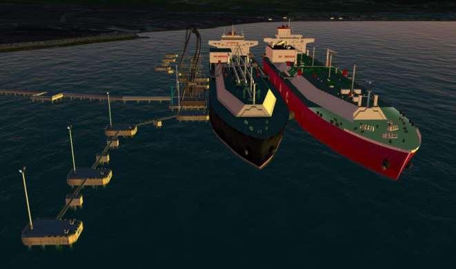
7 3. LOCATION AND GENERAL INFORMATION -water -western 4. DETAILS OF THE TERMINAL AND BERTH consists of a steel piled and concrete capped jetty which encompasses berthing and mooring facilities for a 145,000 m3 Floating Storage and Regasification Unit (FSRU) utilized for the import storage and regasification of Liquid Natural Gas (LNG). The terminal jetty fendering and mooring arrangements are designed to moor the accordance with OCIMF guidelines. The design of the berth and the FRSU mooring arrangements permits two (2) vessels to be moored in a double-banked configuration while conducting LNG STS transfer operations with the outboard (seaward) LNGC discharging into the FSRU and the FSRU conducting regasification of LNG and delivering high pressure natural gas into a purpose built high pressure gas marine unloading arm. 6

8 7

9 4.1. BERTHING LIMITATIONS Max. Allowable Displacement: Tons (Q-Flex) Minimum Water Depth: 17 m. Length of Berth: 415 m. Max Allowable Draft: 14 m. Max Allowable LOA: 345 m. Minimum Under Keel Clearance: 3 m. Salinity: Concrete cap on pilings with fixed fendering 6 mooring dolphins and 3 breasting dolphins Symmetrical to lineup of vapor manifold of FSRU. Manifold and Mooring Layout: Wind speed limitation and action associated: for refrigerated liquified natural gas carriers (LNG) last edition. Please refer to section 13- ENVIRONMENTAL LIMITS of this manual. 5. PORT LAYOUT AND BATHYMETRY 8
10 9
11 6. ENVIRONMENTAL CONDITION General Information: As a routine, twice a day weather forecasts are received and made available by the Terminal to the FSRU Master. And, in particular, Adverse Weather Forecasts, when received, are reported to the FSRU Master as described. Such weather forecast is by their nature only indicative of conditions that may be experienced. Neither FSRU nor the Terminal Operator accepts any liability or responsibility whatsoever for the accuracy or otherwise of any weather forecast made available by the Terminal Operator. 7. LNG CARRIER DOMESTIC MATTERS into account that only the support/service vessels registered/permitted by the Harbor Master are allowed to enter Terminal sea area. Provisions, stores deliveries and crew changes Terminal permits to accommodate provisions and/or stores deliveries at the deliveries prior to cargo operations, or after cargo operations. The LNG Carrier may, in exceptional cases, carry out stores, provisions deliveries or effect crew changes from support/service vessels when alongside, and in any case before the commencement of Cargo Operation, only with the prior permission of the Terminal Director. As a general rule, while the LNG Carrier is under cargo operations, support/supply vessels may not approach the LNG Carrier and stores, provisions and/or spares may not be loaded or unloaded. Repairs Medical care emergency While the LNG Carrier is alongside the Terminal, repairs are prohibited, unless otherwise agreed by the Maritime Authorities and the Terminal Operator to facilitate safe or continued operations. While there are no medical facilities available on the Terminal, medical evacuation to shore may be organized akes requests to the Terminal Operator for logistical arrangements for the evacuees upon arrival on shore. Bunkers and potable water Garbage Facilities There are no bunkering or potable water facilities at the Terminal. Bunkering activities are not permitted at the Terminal or within the Port Limit. There are no garbage reception facilities at the Terminal. 10
12 8. COMMUNICATION INFORMATION All communications between the Terminal and LNG Carrier and Ship language. Item Description Channel 16 and 74, 24 hours per day Channel 69 Terminal Details Terminal Terminal Telephone CCR / 176 (ext.) PFSO Mobile FSRU NEPTUNE master.nept@hoeghlng.no FSRU NEPTUNE telephone FSRU NEPTUNE Satellite PRE- ARRIVAL COMMUNICATIONS estimated times of arrival (ETAs) to Maste Name of the LNG Carrier The quantity (in cubic meter) and quality of LNG loaded and the portion of such quantity to be unloaded at the terminal. All subsequent ETA notices should include cargo condition i.e. cargo temperature and cargo tank pressure relevant to specific ETA notice. The amount of heel to be kept on board LNGC after completing discharging as well as an estimation of quantity to be unloaded to be stated as well. The ETA and any operational deficiencies in the LNGC that may affect ifs performance at the Terminal or berth. ETA Notice of the LNG Carrier shall be submitted, updated or confirmed (as the case may be) at the following intervals, subject to the Maritime Safety Regulations: (i) ninety-six (96) hours before arrival at Pilot Boarding Station (PBS); (ii) seventy-two (72) hours before the then current ETA; (iii) forty-eight (48) hours before the then current ETA; (iv) twenty-four (24) hours before the then current ETA; (v) twelve (12) hours before the then current ETA; and (vi) (vii) thereafter for any ETA change of more than one (1) hour. If the cargo to be unloaded has been acquired by or diverted to the Terminal, after the departure of the LNG Carrier from the load port or after the relevant time specified above, then the ETA Notice shall be submitted as soon as possible after such acquisition or diversion, but in any event taking into account any applicable requirement for the final time by which the arrival of LNG Carrier shall be notified to the Maritime Authorities. 11
13 (viii) Subject to any applicable restrictions, including any night-time berthing restrictions imposed by Harbor Master, or any other public l authorities or pilots or any other reasonable timing restrictions upon arrival of such LNGC at the PBS (Pilot Boarding Station) and when that LNGC is ready to berth and to unload LNG in all respects. When in VHF range of the Terminal the LNG Carrier shall contact with the FSRU and maintain a listening watch on the FSRU VHF Operating Channels. Pre-arrival information is to be, in any case, transmitted to the Terminal and FSRU no less than 72 hours prior to arrival at the Terminal. The following checks and tests must be carried out successfully on board the LNG Carrier and duly recorded within three days prior to the estimated time of berthing: Water Spray systems Fire pumps Inert condition of annular space, primary and secondary space if applicable Operation of cargo system remote control valves and their position indicators Alarm function of fixed gas detection equipment Primary custody transfer and alarm set points Operation of the ESD system to the Terminal and to the Master of the FSRU. The Master at the pre-transfer meeting. legislation 9. PILOTAGE & TUG BOATS In general, the capability, size and number of the ship assist tugs required to serve the vessels calling at the studies conducted by Dokuz Eylül Üniversitesi - Maritime sumptions: Port facility and ship safety concerns Emergency response For each vessel calling at ET the minimum level of vessel services, including the number of Pilots, ship assist tugs (size and capability), along with the deployment of escort and security vessels, mooring line handling vessels and standby tugs in the Port additional services, based upon their respective Safety Management System requirements. Specific arrangements should be made through their ship agents. 12
14 Pilotage is compulsory for LNG vessels for berthing and unberthing. VHF Contact should be established with the Pilot station on Channel 16 when within range. Two pilots will board the vessel at the Pilot Boarding Station, (pilot ladders/combination ladders, etc.) shall comply with SOLAS Chapter V Reg. 17 and other relevant IMO requirements. Pilotage and Tugs services are provided by third party in line with local regulations. ( Stand-by pilot shall be on board the LNG/C during STS operation as per Harbor to stand-by pilot, two stand-by tugs will be available at Terminal during STS. In addition LNG Carriers. 10. BERTHING & UNBERTHING OPERATIONS & CRITERIAS Berthing schedule shall be determined by the Terminal Operators in accordance with its procedures and obligations to its users, subject to the FSRU available storage capacity and any contrary requirements of the Terminal Authorities. Berthing is prohibited at night-time. Unberthing is allowed by Harbor Master after sunset and subject to below conditions: - If there is a request from the authorized pilotage organization, in which case additional tugs shall be provided, - Departure maneuvering shall be done under weather conditions which the authorized pilotage organization approves. 11. BERTHING APPROACH All Maneuvering of LNG Carriers proceeding to and within Port Limits shall be conducted within appropriate care and caution at the speed and in a manner. At appropriate position within port limit the Tugs must be connected to the forward and aft ends of the LNG Carriers. Final transverse approach / berthing speed of the LNGC should not be more than 0.15 m/sec. Berthing approach speed is followed by pilots via approved suitable equipment. 13

15 14


16 12. MOORING AND MOORING ARRANGEMENT 12.1 MOORING LNG Carriers designs. All mooring and breasting dolphins as well as mooring point on FSRU are equipped with quick release mooring hooks which are load sensored and are monitored with a Tension Monitoring system located in the main terminal control room, FSRU cargo control room and also can be monitored locally. 15
17 The LNG vessels range up to Q-Flex size shall be moored, unless a different mooring arrangement is submitted to and approved by the Terminal Management in advance. The following best practices / guidelines, based upon OCIMF and SIGTTO guidelines, shall be followed for the lity: The Master is responsible for ensuring that mooring lines are in good condition and that winches and securing devices are properly maintained in safe & efficient operational order. Mooring shall be completed as per recommendations of the STS compatibility study in compliance with the technical studies upon Under no circumstances should a mixture of wires and synthetic lines (mixed moorings) in the same direction of service and to the same mooring point be acceptable. FSRU when the LNGC is parallel with the FRSU about 50 meters off Mooring boats shall be used to run the head and stern lines of the LNGC to the shore mooring dolphins (BD-1 and BD-6) quick release hooks (QRH). Final transverse approach / berthing speed of the LNGC should not be more than 0.15 m/sec. The maximum permitted angle between the LNGC side and the fender-line for landing the LNGC on the fenders is ten (10) degrees The Master should endeavor to ensure compliance with the mooring layout. holding power of the mooring winch system. Automatic tension winch settings shall not be used. to ensure that all lines are properly tensioned to prevent undue movement of the vessel. The vessel must In order to avoid damage to cargo transfer hoses and the HP gas arm, the vessels shall be kept close alongside at all times. reported to the TERMINAL DIRECTOR by the Master in order that, if necessary, additional precautions may be agreed upon. Any additional measures, if required for mitigating defects should be agreed upon between the Master of the LNGC, the Master of the FSRU and the TERMINAL DIRECTOR. LNG carriers will be berthed to FSRU from starboard side alongside 12.2 MOORING ARRANGEMENT hooks (QRH) are fitted. Each QRH has a mooring load cell incorporated within it which allows for remote monitoring of mooring line loads. The actuation of the QRH function is also controlled locally and from the FSRU. QRH actuation is on a hook-by-hook basis in order to avoid unintentional release of all lines. 16
18 The general arrangement of the mooring system is as follows: Mooring Dolphin BD-1: QRH No.1 3x150 ton of SWL QRH No.2 3x150 ton of SWL Mooring Dolphin BD-2: QRH No.3 3x150 ton of SWL Mooring Dolphin BD-3: QRH No.4 3x150 ton of SWL Breasting Dolphin YBD-1: QRH No.5 3x150 ton of SWL Breasting Dolphin YBD-2: QRH No.6 3x150 ton of SWL Breasting Dolphin YBD-3: QRH No.7 3x150 ton of SWL Mooring Dolphin BD-4: QRH No.8 3x150 ton of SWL Mooring Dolphin BD-5: QRH No.9 3x150 ton of SWL Mooring Dolphin BD-6: QRH No.10 3x150 ton of SWL QRH No.11 3x150 ton of SWL FSRU NEPTUNE MOORING LAYOUT: 17

19 13. ENVIRONMENTAL LIMITS The Following Tables show the prescribed environmental limits for certain operations. This information is provided within the prescribed environmental limits, these operations are always subject representative, the Pilots and Maritime Authorities. Limits are based on sustained wind of a minimum 15 minutes duration for all vessels, except for Q-Flex, which are based on 6 minutes sustained wind speed duration. 14. SHIP TO SHIP (STS) OPERATIONS All STS operations should be done according to Höegh LNG Ship to Ship Information Manual. 15. PRE-TRANSFER OPERATIONS 15.1 Tests and Inspection Prior to LNGC Arrival The visiting LNGC ship shall perform the normal pre-arrival tests, inspections and preparations as for typical shore terminals, as follows: Low cargo tank pressure; Liquid temperature shall not be warmer than -159 C; Liquid manifolds shall be cooled down and drained before arrival; Manifold shall be cleaned, purged and ready for opening (singled-up to 4 bolts) Air & N2 hoses and connections ready. Fire hose (to fill saddle with water) laid out; SW Ballast system tested; Gas meters tested; Cargo alarms set points checked and annunciator tested; ESD system tested; Portable deluge system and water bath dams installed below manifolds and Pre-Arrival tests, inspection checklists completed. 18

20 Each LNG Carriers that the user intends to moor alongside and unloaded to the FSRU at Port area shall be in compliance with International standards, to be approved by the FSRU and Terminal Operator having successfully passed a Compatibility Study Process and detailed hereinafter and have passed all inspections. (Approval & Vetting Procedures and Scheduling procedures for incoming Cargo to FSRU.) SCHEDULING PROCEDURE FOR INCOMING CARGO TO THE FSRU VETTING CRITERIA AND OPERATING STANDARDS FOR LNG VESSELS LNG SHIP ACCESS TO HÖEGH LNG FSRU SIDE BY SIDE OPERATION 15.2 STS Fenders The FSRU shall have four (4) Yokohama fenders rigged on the port side. Two (2) of the fenders are rigged aft of the LNG cargo manifold and the remaining two ( the upper fore and aft limits of the parallel mid-body. The fenders and rigging are subject to inspection prior to each STS transfer operation Pre-Cargo Transfer Meeting After the LNGC/FSRU Safety Checklist & Cargo Handling Agreement have been completed and prior to the - The attendees of this meeting shall be the LNGC officer recognized and legitimate interest in the cargo transfer operation. 19
21 The purpose of this meeting is to ensure that all aspects of the cargo transfer and associated activities are include as a minimum for normal cargo transfer, but not necessarily be limited to the following: Status of cargo tanks on arrival (temperature and pressure) Sequence of ESD tests Cargo hoses Cool-down procedure Vapour handling Ramp up Bulk cargo transfer procedure Ramp down Drain purging and disconnecting Ballasting Anticipated weather and sea conditions. Communications between FSRU, LNGC & (stand-by tug if any). Emergency Procedures Maritime Security 15.4 LNGC is all fast alongside the FSRU and ready to may be required. ities as return hoses are disconnected from the LNG Carrier and the LNGC is cleared for departure and able to depart. consecutive hours for LNG Carriers having a cargo capacity up to cubic meters. Any time lost as a result of any of the following shall be added to Allowed Laytime: a. reasons attributable to the fault of the LNGC or its master, crew, owner or operator; b. Force Majeure; c. Adverse Weather Conditions; d. waiting time for daylight requirements as per the instructions of the Harbor Master; e. time spent for the stripping operations if required by the Master of LNGC; and f. decree Bills of Lading 20
22 The Bill(s) of Lading for the cargo to be discharged shall be handled by the owners of the LNGC and their local agents. The Master of the LNGC, owners / operators and charterers, if any, shall take utmost care to have the requisite authorization for the Master of the LNGC to commence discharge operation without any delays. Receipt for cargo laden by STS transfer Cargo Survey, Documentation, Customs and Agents appointed agent will arrange port entry and customs clearance after berthing. Clearance by authorities must be given prior to any operations can commence. Custom officials and other representatives are disembarking the LNGC via launch at berth Emergency Shut Down Systems Each vessel involved in the STS transfer operation shall have an emergency shutdown (ESD) system which enables a rapid and controlled means of stopping the cargo transfer and isolating the free communication of LNG and FSRU between the vessels in the event of an emergency. Modified arrangements may be required for vessels engaged in a STS cargo transfer in order that both ESD systems are compatible. This shall be addressed in the Compatibility Study. The ESD system shall comply with the SIGTTO guidelines for linked ESD systems. hoses in the event of vessel separation releases the cargo transfer 15.8 Linked ESD Systems The cause and effect of shutting down cargo transfer in an emergency shall be discussed and confirmed by both vessels prior to commencement of the cargo transfer. Vapor management and the actions surrounding recovery from an ESD shall also be confirmed. fitted in the umbilical between the two vessels. The weak link is a failsafe in case of vessels drifting apart. The means of linking the ESD systems of the vessels shall be addressed in the Compatibility Study Testing of ESD Systems Prior to arrival, the ESD system shall be thoroughly tested by both vessels as required by the IGC code. All methods of activation should be tested and the timing of the ESD valve closure shall be noted. The closing times and sequencing of the ESD valves shall be more than 15 and less than 30 seconds ensuring pressure surges do not occur. The FSRU ESD valves are timed to close within 30 seconds. The LNGC should set its valves to close within 25 seconds. Prior to commencement of the cargo transfer (hose cool down), the linked ESD system shall be tested by both vessels in accordance with the IGC code. The ESD shall be tested once cargo transfer hoses are connected and purged. It is important that the ESD valves are not operated before purging has been completed since the cargo transfer hose and spool pieces may contain oxygen and moisture. 21
23 The procedure for testing the linked ESD system shall be addressed in the Compatibility Study and confirmed at the pre-transfer safety meeting. The vessels shall agree to the sequence and number of tests to be conducted Communications Failure In the event of a Communications failure between the vessels, all cargo transfer operations shall shutdown until the cause has been identified and Communications between the vessels re-established Mooring Integrity & Safety Checks Prior to connecting the cryogenic flexible hoses/or commencement of the Pre-Cargo Transfer Safety Meeting the FSRU Master or his authorized deputy shall together with a responsible LNGC officer check and confirm that all moorings are tight, brakes properly hardened up and winches are out of gear, Firefighting equipment is deployed, offshore manifolds are fully blanked and tight and other areas of general safety. There is no obligation to rig the fire wires. On completion of confirming mooring integrity and safety, and following the conclusion of the safety meeting connection of unloading arms may proceed. The Master of the FSRU and LNGC shall ensure the vessels are moored properly according to the approved mooring layout. Any deviations in the mooring arrangement shall be brought to the attention of the TERMINAL DIRECTOR Water Spray Hull Protection System Once the LNGC is moored to the FSRU, and before the cargo transfer hoses are connected, the water curtain should be started on both vessels. After completion of connecting the cargo transfer hoses, each vessel is responsible to establish a water bath and water cascade on the trunk deck slope under the cargo manifold. The fire main shall remain pressurized at all times on both the FSRU and the LNGC Communications Alongside Communications between LNGC and FSRU shall be established before commencement of cargo transfer operations. Communications systems shall be included in the ship compatibility study and shall be confirmed during the pre- transfer safety meeting. The FSRU shall provide the communication links between the vessels. In addition, the FSRU shall provide the LNGC with a hand-held UHF Radio, spare battery and charger for use during the unloading operation. A receipt for the radio shall be signed by a responsible officer from the LNGC Gas Burning 22
24 Gas burning on board of the LNGC can be accepted related to commercial terms and condition outline in the commercial agreements. LNGC equipped with reliquefaction plant may use it as per their requir TERMINAL DIRECTOR or LNG operations representative Opening Custody Transfer Measurement Before the LNGC's manifold valves are opened at the start of line cooldown the opening CTMS shall take place. The opening CTMS shall take place on both vessels simultaneously, therefore clocks on each vessel should be synchronized accordingly. This is usually done following the safety meeting. The CTMS on the LNGC shall be witnessed by an independent surveyor. The CTMS is conducted in compliance to the standard GIIGNL guidelines. In the event of a primary gauging system failure, the secondary gauging system shall be used for CTMS. Vessels should NOT secure gas burning prior to or during gauging unless otherwise agreed Cargo Transfer Hose Specification and Testing Flexible cryogenic cargo transfer hoses are stowed on board the FSRU and provided to the LNGC for cargo transfer. When not in use the hoses are stowed in a dedicated wooden hose rack in a horizontal position, stowed with a slight positive pressure and protected from the elements by tarp. The hose rack allows for: Storage of 9 hose lengths, allowing for 1 spare length of hose; Visual inspection and dew pointing of hoses at regular intervals; Pressure testing of hoses per Class and OEM requirements; and Ease of hose handling for the crew with the manifold crane. The cargo hoses are a nominal 250 mm) diameter by 15 m. length, composite hose, type approved for the emergency cargo transfers. Class certificates for the cryogenic hoses may be found in a certificate. 23
25 An annual pressure test of each hose shall be conducted and results recorded by the FSRU. Due to the construction of the hose it may not possible to stencil the test date to each hose. The annual pressure test shall be nitrogen gas will be used to conduct the pressure test. When the cargo transfer hoses are stowed and not in use, the hoses shall be stowed and maintained with a positive-pressure nitrogen blanket inside Emergency Release (Hose) Couplings Each liquid and vapour hose used for the ship-toemergency release coupling (ERC). The coupling is an emergency release device with internal double closure valves activated by an integrally mounted hydraulic release mechanism. The ERC are Class approved and are able to function with ice accumulation up to 25mm in accordance with IGC code requirements. -againstfeature which certified and Class approved. The ERC will function against full rate flow to prevent release of LNG in the event of an ESD-2 actuation. The ESD-2 is integrated into the ESD-1 function to ensure ESD-1 occurs first Cargo Hose Support Saddles Hose support saddles are specially designed and fabricated for use in supporting the cargo transfer hoses as they cross the manifold hand railing of both vessels. The saddles are designed to support the loads of the cargo 24
26 hose with the LNG volume, maintain the minimum bend radius of the hose and manage the dynamic loads transferred to the vessels manifolds. The saddles shall be placed in the correct location by the crew of both vessels. The FSRU will have hose saddles on board that shall be transferred to the manifold of the LNGC. The saddles rigged on the cargo manifold of the FSRU contain a braking system to allow the safe automatic descent of the cargo transfer hoses in the event of an ESD-2 emergency disconnection. Cargo Hose Support Saddle Specification Primary material: Plate thickness: Other materials: Stability: Draining: Seawater resistant aluminum ASTM 5083 (nonstructural) and 5383 (structural) 8mm (structural) 6mm (nonstructural) Teflon sheet (3mm) in way of flexible hose, 400mm wide Wooden plate between saddle bottom and platform grating Provided by filling the bottom tank of each saddle with seawater, maximum 500mm depth - approximately 1 ton One large hole for quick draining while in place on manifold platform. Screw in plug accessible from manifold side Securing / Horizontal: Weight: By ratchet straps with rim fixed by clamps on the manifold gutter plate, with the rim running around the entire saddle 738 kg dry and 1477 kg with water ballast. The Master of each vessel shall ensure the following prior to beginning hose connection: No visible damage to the Teflon sheet that could damage hoses Bottom ballast tank of each saddle is filled with seawater Horizontal securing strap and putting blocks are in place Vertical securing straps and wooden floor-plate are in place with saddle properly adjusted for height The hose support saddle is stable 25
27 26
28 27
29 28
30 15.19 LNG Cargo Hose Connection STS equipment handling and hose connection shall be in compliance with the FSRU Cargo Operation issued to the LNGC by FSRU before arrival. It is of utmost importance that the instructions contained in the manual are followed by all personnel involved. The crew of both vessels shall avoid external damage and excessive bending involved in rigging the cargo transfer system in a manner similar to other types of STS operations. Since the crew of the LNGC shall be actively involved in the hose connecting operation, a copy of the STS Equipment Handling Manual for Höegh shall be supplied to LNGC in advance of the operation. If the Master of the LNGC does not have the manual on board, it should be requested in advance. The hose handling and connection process is supervised by the officers of each vessel however one officer from the FSRU will be present to assist the staff of the LNGC. Hose buns designed to support and protect the composite hose when lifted by the crane shall be provided by the FSRU. The wyethe respective liquid manifolds and the vapour manifold. Insulation flange sets shall be installed on board the LNGC in each hose string. All bolted flange connections shall be set with a torque of Nm, each with a new packing installed. The responsible LNGC officer shall verify the torque settings on the LNGC manifolds. Liquid manifold connections not used for the cargo transfer shall remain blinded and secured with bolts / nuts in all flange connection holes. Usually the cargo transfer hoses shall be connected starting with the second liquid manifold connection (L-2) and working aft until all hoses are connected. On each liquid manifold, a reducer 16" to 10" spool piece shall be bolted with a new packing and all twelve (12) bolts properly torqued. On the vapor manifold Y-piece is used Wye-Reducer Spool Piece Specification Primary material: 316 SUS Schedule 80 Pipe thickness: Flanges: Weight: Lifting sling: ANSI 150, RF 175 kg Permanent 6 mm SUS wire, tri-pod sling with lifting eye above center of gravity to maintain horizontal presentation The FSRU shall supply and transfer the wye-reducer, straight reducer and spool pieces to the LNGC and the guide pins or spuds (tapered bars with hand grips) are used to guide and align the hose flange bolt holes with the holes on the spool piece presentation flange. 29
31 FSRU Side: 30
32 31
33 LNGC Side: 32
34 33
35 15.21 Cargo Hose Inerting and Flange Leak Test Once the cargo hoses are connected, the manifolds, spools and hoses shall be purged of oxygen using nitrogen supplied by the FSRU. The pressure shall be raised to 5 bars in the liquid lines and 1.0 bar in the vapour line. The pressure shall be maintained while a leak test is carried out on the flanged connections using a soapy water solution. Once the leak test has been completed the pressure shall be released to atmosphere by the LNGC and the hose atmosphere shall be tested. Purging is considered complete once the O2 is < 5%. All hoses shall be depressurized to 0,5-1.0 bar after the leak test and purge Warm ESD Test In addition to any tests that may be carried out by the FSRU prior to the LNGC's arrival, ESD tests shall be conducted in conjunction with each arriving LNGC. When both FSRU and LNGC have confirmed ready for test, the LNGC shall initiate an ESD. After resetting the FSRU shall initiate an ESD test. ESD procedure shall be agreed at the Pre-Cargo Transfer Meeting. All valves and equipment connected to the ESD system must be operating properly when the ESD System is released. Upon completion of a successful ESD test, the cool down operation is ready to commence 16. CARGO TRANSFER OPERATIONS Hose and Manifold Cooldown During LNGC arrival pilotage and hose handling operations the cargo lines shall be cooled down up to the inboard manifold double-block valve in order to avoid the risk of LNG passing across an ESD valve during flanging operations. Line cooldown is considered to be complete once the fwd. and aft liquid cross-over lines are < -110 C. Line cooldown can commence during LNGC pilotage so long as personnel are available for safely conducting the operation. The line cooldown process shall be addressed during the vessel compatibility study and confirmed during the pre-transfer safety meeting. During hose and line cooldown, the integrity of the hoses, flanged connections and the manifold area shall be closely monitored. Cargo hose cooldown shall be initiated with the free flow liquid from the FSRU and continued, on the request from FSRU minutes. The cooldown shall be conducted with the LNGC ESD valves open and the manifold double-block valves closed. The rate of cooldown shall be controlled with the cool down valves on the manifold coming from the spray header. The liquid manifold valves on the FSRU shall remain closed. The coolant shall bypass the ESD valves flowing into the stripping header towards the spray line at the vapour dome until the spool piece on the FSRU is 50% frosted. 34
36 16.2. Cold ESD Test Before initiating the cold ESD test both LNGC and FSRU shall confirm their readiness to each other to conduct this test. The FSRU following a countdown will initiate the ESD. Both LNGC and FSRU will check their respective ESD valves for proper closure. Closing time of both LNGC and FSRU valves are to be recorded. Only one ESD is required. One ESD is initiated from the LNGC and one from the FSRU (Pyle and Optical) and the opposite during warm test Cargo Transfer The FSRU will be in charge of the cargo transfer due to the FSRU being the receiving and production facility. The cargo operation will be executed in careful cooperation between the LNGC and the FSRU. with at all times. These procedures are based upon best industry practice and SIGTTO recommendations. The FSRU and the LNGC will line up respectively for the cargo transfer. When all parties have completed the cargo pipe lineup and are ready for cargo transfer, both FSRU and LNGC Officers in charge of transfer will acknowledge to each other that cargo transfer can commence. One of primary variables that dictate the LNG cargo transfer rate is the regasification rate of the FSRU into the pipeline. The LNG cargo transfer rate may have to be reduced in order to control FSRU tank pressure and levels within operating limits. STS cargo transfer is designed for a rate of up to 6,000 m³/hour, however in its sole discretion the FSRU will advise on the maximum loading rate for the individual discharge. During the LNG cargo transfer a carefully check of the tank pressure must be maintained throughout. To maintain tank pressure on the LNGC BOG from the FSRU will be returned via the vapour system utilizing the pressure difference. Simultaneously with the cargo transfer the LNGC will be ballasting and the FSRU will be de-ballasting accordingly. Both the FSRU and the LNGC must have a stability plan prepared for this operation. Ramping up and down rates shall be discussed at the pre-transfer meeting. However, the ramping up can be slowed down if either party feels uncomfortable with the situation. Normal ramp up is expected to take one (1) hour. Starting cargo transfer and subsequent increases in transfer rate shall be authorized by the FSRU to ensure that tank pressures are managed in a safe manner. During the transfer, an hourly exchange of information shall take place between the vessels. This shall include (but not limited to) cargo transfer rate, tank pressure, cargo ROB quantities, mooring line status, etc. The ramping down process shall be discussed and agreed to at the pre-transfer safety meeting. 35
37 16.4. Vapour Management Vapour will be returned to the LNGC via vapour manifold on free flow basis. The flow will be controlled by FSRU on request from LNGC. The set point will be agreed during pre-discharge meeting however LNGC shall arrive with no more than 140 mbar(g) in its tanks. The operation pressure on the FSRU is set out by the overall operation of the terminal and independent from the individual discharge operation. It is the responsibility of the LNGC to monitor the pressure in its tanks and keep the FSRU informed. In the event that pressure in the return gas line falls to 80 mbar(g) or below then the LNGC must adjust its unloading rate until pressures return to normal levels. It is important that FSRU Cargo Control Room is informed if there is any problem with the ship taking return gas in order that the FSRU can manage vapor pressure in the FSRU cargo tanks by other means (MSO compressor - gas combustion unit). In case of raising tank pressure on the LNGC side the FSRU Cargo Control Room needs to be informed immediately for further action Topping Off Topping off shall occur at the pre-agreed reduced rate, one tank at a time. A topping off rate of m3/hr is normally agreed upon. There may be an increase in the effect boil off has on tank pressures whilst tanks are being topped off, this is due to the construction shape of the prismatic tanks. Adequate precautionary measures shall be taken in order to avoid possible venting Stripping / Heeling Out Heeling out operation is permitted, if commercial terms and conditions are in agreement with this operation. Under no circumstance the contractual lay time should be exceeded due to the heeling out operation unless otherwise agreed with Terminal Operator. Stripping pumps shall be started in ample time if the discharging vessel intends to heel-out (strip) cargo tanks. This shall ensure cargo consolidation can be completed if the main cargo pump loses suction due to liquid movement. The minimum LNG liquid level accounted in the custody transfer is the height of liquid, where the accuracy equal to or better than plus or minus five (±5) millimeters over the relevant measurement ranges of the cargo tanks as outlined in the calibration table of the vessel. Any liquid level below the minimal height may not be accounted for, therefore it is usually recommended to heel-out with some level of innage remaining. Heeling out operation shall be discussed during the pre - discharge meeting and vessels shall limit their trim to less than 3.0m throughout the stripping / heeling out operation Cargo Hose Drain and Purge Once the cargo transfer operation has been completed, the ESD valves on the manifold of the FSRU shall be closed. On the LNGC the double-block valves shall be closed while the ESD valves remain open. 36
38 Open to allow draining of the vertical risers and cargo transfer hoses. All cargo transfer hoses shall be drained from the FSRU towards LNGC. Draining shall be conducted by repeatedly pressurizing the hoses using nitrogen until the pressure reaches four (4) to five (5) bar and then opening the LNGC manifold ESD bypass valves until the hoses are liquid free. During this operation sea water spray shall be directed onto the LNG hose bight (catenary) to speed up de-icing and vaporization of remaining LNG in the hose. As the LNG boils-off, the line pressure increase will assist in displacing liquid in the lines. Both vessels shall conduct the drain and purge operation together. Cargo hoses shall continue to be purged with nitrogen until they contain an atmosphere of less than 2% methane by volume. Hoses may then be disconnected, blind flanges installed and the hoses passed back to the FSRU Cargo Hose Disconnection The cargo hoses shall be disconnected and handled in accordance with procedures in the STS Equipment Handling Manual for Höegh provided to the vessels. After disconnection, each hose flange shall be blanked prior to returning the hose to the FSRU. The manifold ESD by-pass valves on the FSRU shall be partially open to prevent any pressure build up in the cargo transfer hoses Closing Custody Transfer Measurement CTMS may commence. The independent surveyor shall be present at the closing of CTMS. The representatives of interested parties same as on opening CTMS will be ready on board on completion of cargo calculation and agreement of the cargo quantity transferred to sign the documents which shall be prepared onboard the LNGC. addition to standard CTM prints, the LNGC should provide screen prints from the control system to demonstrate vapor handling on board the LNGC for engine room, GCU or reliquefaction unit consumption Removal of ESD Cable The ESD Cable should be disconnected after the cargo hoses have been disconnected and water curtains are secured Pilots If the order for the pilot is placed a significant time before the one (1) hour pilot order deadline, LNGC Master should ensure that the pilot order is reconfirmed one (1) hour before the intended departure time. 37
39 17. ACCESS & SECURITY Security Berth/LNG Carrier Access Control or Terminal Representative is allowed to board or disembark from the LNG Carrier until clearance has been obtained from the Maritime Authorities having jurisdiction over the Terminal and the LNG Carrier. The Terminal Operator, among other things: reserves the right to request that personnel produce personal identification, reserves the right to escort to or from the LNG Carrier any visitors or persons whose conduct may present a hazard to personnel or Terminal property, reserves the right in order to ensure that the Terminal Regulations are being observed to board the LNG Carrier at any time with a nominated person. has the sole responsibility of controlling access to the Terminal area and the Exclusion Zone. LNG Carrier crew personnel access to the Terminal is not permitted without prior approval from the TERMINAL DIRECTOR. If it is permitted, it will be exclusively with a Terminal personnel escort Access Between the FSRU and LNGC The FSRU is fitted with personnel transfer basket (Billy Pugh). The personnel transfer basket will land aft of the LNGCs cargo manifolds -arrival compatibility checks. and has received Port Clearance from relevant Authorities so that the personnel Due care and caution shall be exercised when transferring personnel between vessels using the personnel transfer basket. The crane utilized to lift this basket shall be certified for lifting personnel and the crane operator and supervisor properly trained. Certification of the crane(s) used for personnel transfer shall be confirmed during the STS compatibility process. FSRU Officer who operates the equipment that it is safe to land the personnel transfer basket. Thereafter boarding of FSRU personnel can take place. 18. LNG CARRIER EMERGENCY ESCAPE The following pertains to emergency escapes: A pilot ladder or accommodation ladder shall be rigged or positioned on the outboard side of the LNG Carrier. The accommodation ladder shall be swung outboard ready for immediate lowering in case an emergency escape is required. The port side lifeboat, if fitted and unless it can depart from a stowed position with all personnel inside, shall be lowered to the embarkation level or be ready for immediate use in case of emergency. 38
40 The Terminal Representative will review with the LNG Carrier Master during the pre-transfer meeting emergency evacuation arrangements, including reciprocal arrangements in case of the need to evacuate the Terminal and remove the LNG Carrier from the berth. 19. SECURITY ISPS All security related questions should be addressed to the Terminal Representative. the "Declaration of Security" which shall be signed also by the LNG Carrier security officer or the Master and will concur with the LNG Carrier security officer on any additional security measures in case the LNG Carrier or Terminal is at a security level other than 1. The LNG Carrier could be at a higher security level than the Terminal, but never at a lower level. Declaration of Security will be signed between LNGC and FSRU at the pretransfer meeting. 20. SAFETY Introduction The safety requirements have been developed based on OCIMF (ISGOTT), SIGTTO and other industry accepted Master and crew MUST take all necessary safety precautions (whether or not so advised by the Terminal Representative), keeping in mind the hazards of LNG discharge operations, weather conditions and any other circumstances requiring special care or caution. The main engine shall be kept ready for immediate use. Running any tests on the main engine of the LNG/C is not allowed during STS operations. Urgent repairs may only be undertaken with written form approval from the TERMINAL DIRECTOR. Repairs which are restricting the maneuverability of the vessel may only be carried out and will be conditional on the Master hiring sufficient standby tugs to move the vessel if so required. All consequential costs resulting from repair work carried out on the vessel while it is moored at the Terminal shall be borne by the vessel. Should the repair works represent a risk for the terminal or should the conditions of the approval be costs. 21. HAZARD SITUATIONS & EMERGENCY RESPONSE The Masters shall at all times retain sufficient crew on board to operate their vessels in compliance with the 39
41 21.1. Fire and Safety Repair Work and Maintenance No boiler cleaning, chipping, scaling and scraping of steel work or work likely to cause sparks shall be undertaken on any vessel (and no iron or steel hammers or other instrument capable of causing sparks shall be used for the purpose of opening or closing hatches), unless the previous written permission of the TERMINAL Engineer on Duty In addition to the supervision required on deck a competent Engineer must be on duty in the engine room and or boiler room at all times whilst the vessel is berthed of the Terminal Excessive Funnel Smoking Soot blowing and excessive funnel smoking is prohibited and immediate steps must be taken to eliminate sparking from funnels Fire and Fire Fighting For an emergency on shore, jetty or FSRU, an emergency by giving the sound of siren. Refer to Emergency Contact and Signals for further details Fire Fighting Equipment Vessel(s) shall be adequately manned at all times for firefighting and for vacating the berth in case of an emergency. The following firefighting precautions shall be ready: Fire hoses to be run out fore and aft, ready for use Fire main must be under pressure Dry chemical extinguishing equipment of adeq In the Event of a Fire Ashore All cargo operations and/or ballasting operations must be stopped immediately and the Master shall prepare the vessel for immediate departure and await instruction from the TERMINAL DIRECTOR or Terminal and deck In the Event of Fire Aboard Advise jetty operator, FSRU / LNGC as applicable and sound the alarm. Shutdown cargo operations and activate the water deluge as necessary. remains with the Master. The vessel Master may request assistance from the FiFi tugs available in the port. 40
42 Generally, the fire brigade will be on the scene first and will on request of the Master assist in combating the fire. Refer to ANNEX CCC Fire Notice for further details Emergency Towing Wires There is no obligation to rig the fire wires Venting Gas to Atmosphere Venting of natural gas to atmosphere is not permitted during normal operations. The need for emergency venting shall minimized through the process of tank pressure manag board the FSRU or LNGC. In the case of emergency venting, the gas shall be heated and cold venting avoided. The water spray deluge systems shall be in use and all ventilation systems secured during any venting event Thunderstorms/Electrical Storms & Suspension of Operations Lightning hazards may be associated with several severe weather conditions. During periods when lightning/ thunderstorms pose a threat, personnel shall be expected to use prudent judgment and proceed indoors and withdraw from exposed locations. When lightning/thunderstorms are in close proximity to LNG/CNG transfer operations, operations may be temporarily halted until determined that the lighting strikes no longer pose a hazard to personnel working outdoors. Transitions in operations may represent moments of increased risk. Careful evaluation of the circumstances and potential for release of gas should be considered when determining whether to shut down or continue cargo transfer operations with electrical storm activity in the vicinity. It is to note, shutting down regas operations may pose increased risks and therefore may dictate that continuing regas operations to be the safest course of action. In the case of STS cargo transfers, the transfer shall be suspended until the lighting passes. During the suspended period, the cargo transfer hoses may be maintained cold by use of a small spray/stripping pump. The vessel Master is responsible for the safety of the vessel and is responsible for the actions necessary to protect the vessel. Masters should take into account weather factors associated with the lightning / thunderstorms as well as the potential increased risk of gas release during a regas plant shutdown. It is the Masters decision to stop or continue regas operations Personnel Emergency Escape personnel. An accommodation/pilot ladder rigged on the offshore side of the vessel shall be ready for immediate lowering as means of escape in the event of an emergency. cases where they are trapped, they should consider boarding the FSRU as a means to escape. 41
43 21.6. High Pressure (HP) Gas Fire Gas leaking from a pipeline under pressure, if ignited, will give rise to a jet flame. The first action to be taken in case of a high-pressure leak is to isolate the leak and secure the source of gas. Activation of the Emergency Shutdown (ESD) system is the preferred method of action, as the systems are designed to fail safe or shut down into a safe condition. The action taken to manage high pressure leak or fire shall include: Activation of the ESD system on the FSRU; Isolate and secure the gas source; Dispersing or controlling the vapor cloud; Securing potential sources of ignition; In some cases, if ignition has occurred and the fuel source has been isolated and secured, it may be best to allow the gas fire to burn itself out. Adequate spray and/or deluge of water to protect adjacent structures is needed to provide thermal protection. Dry Chemical (Ansul-brand Purple-K or similar) is the preferred agent for extinguishing gas fires under pressure. It is of prime importance to consider the ability to secure the fuel source for all gas fires before extinguishment is attempted. A gas fire consuming fuel in one location that can be managed is a far better consequence than a gas cloud that may find an ignition source somewhere else Natural Gas Fire Natural Gas fires can occur when LNG is released, warmed up, forms a vapor cloud that mixes with an oxygen sufficient atmosphere (the mixture can neither be too lean or too rich) and then comes in contact with an pe where the vapor cloud is held within a confined space such as an enclosed compartment or furnace, or both. The resultant size of a vapor cloud after a LNG release is directly proportionate to the amount of LNG released. In any case, if a natural gas fire breaks out, the first action is to secure the source of fuel to the fire, then create a means of cooling adjacent equipment and exposures using large volumes of water spray. Evacuate personnel as necessary. The decision should be made whether to attempt to extinguish the fire or let it burn itself out. Category I Fire A Category I gas fueled fire is identified as a fire that will probably remain contained, within the specific area of origin, has a limited fuel supply, and does not possess the ability to spread further. The action taken to manage Category I Natural Gas Fire shall include: Primary Firefighting Equipment typically utilized is hand portable dry chemical firefighting extinguisher(s). Water Spray and/or water deluge systems may be employed for thermal protection of personnel and Confirm limited fuel supply source to decide whether to extinguish the fire or allow total consumption of available fuel (burn-out). 42
44 Category II Fire A Category II gas fire is identified as a fire that has migrated outside of the area of origin or initial containment area, has a substantial fuel supply, and if not addressed quickly, could develop into a Category III gas fire. Emphasis on managing unnecessary exposure of unprotected personnel and risk of escalation should be of paramount importance. Emergency response requires containment of the fire and management of the fuel supply source. This will usually be accomplished by isolation of the involved piping or system and controlled vaporization of the LNG released that will typically be associated with this category fire. The action taken to manage Category II Natural Gas Fire shall include: Primary Firefighting Equipment typically utilized is fixed firefighting extinguishing equipment such as total flooding CO2 systems or large dry chemical systems capable of managing substantial fire threat utilizing protected response personnel. Hand portable firefighting equipment must be available as back-up. Water Spray and/or water deluge systems may be employed for thermal protection of personnel and Consider additional resources external to the FSRU such as local offshore service vessels to assist. Confirm fuel supply source to decide whether to extinguish the fire or allow total consumption of available fuel (burn-out). In any case, after extinguishment of a Category I or II fire: A re-flash watch shall be set and adjacent structural cooling shall continue; All involved or damaged equipment or systems shall be inerted/isolated; A damage assessment of the involved equipment or system shall be made; A determination of the root and secondary cause(s) of the fire, including the source of the fuel leak and location of the ignition source shall be made; Corrective actions to prevent recurrence shall be taken before cargo operations are allowed to resume. Category III Fire A Category III gas fueled fire is identified as a fire of catastrophic proportion that has major or total involvement of the FSRU. With a Category III fire, personnel evacuation and preservation of life is of utmost importance. Although, the FSRU involved in a Category III gas fueled fire may be saved from total constructive loss, it is gas fueled fire shall be to manage the resources necessary to fts, service vessels in LNG Spill / GNG Release LNG is a cryogenic liquid, hazardous to personnel due to low temperature. LNG does not burn. Any LNG released to atmosphere will warm and vaporize into Gaseous Natural Gas GNG. GNG is a non-toxic, flammable gas, 43
45 lighter than air at ambient temperatures. In an open atmosphere/non-contained condition, GNG is nonexplosive. The flammable limits of GNG in air are between 5 % and 15 %. There may be slight variation to the flammable limits due to the actual composition of the GNG. The action taken to manage an LNG Spill/GNG Release may include: The use of water spray as the primary means of liquid vaporization and vapor cloud control. The source of the LNG/GNG release shall be immediately isolated and secured. Consideration to force vaporize the LNG with water taking into account prevailing wind conditions and ability of response personnel to control the direction of movement of the GNG vapor cloud that will be generated. provide protection to personnel, vessels and/or support structures as well as provide control of vapor cloud movement and vaporization of LNG Cryogenic Burns - Cold Liquid Contact The effects of cold liquid upon the skin are very rapid and can cause frostbite and freezing. The injury received can be severe, can occur in seconds, and is the same as a burn injury of 1 st, 2 nd, or 3 rd degree. Indications 1 st degree injuries can cause numbing of the skin which may turn white in color. Skin may feel stiff to the touch, but underlying tissue is still soft. 2 nd degree injuries can cause skin to turn white or blue in color and feel hard and frozen. The underlying tissue is still undamaged, blistering is likely. 3 rd degree injuries can cause skin to be white, blotchy, and/or blue in color. The underlying tissue is hard and cold to the touch. Treatment Immediately flush affected areas with clean, cool water. Wrap affected areas with loose, clean bandages. Do not rub affected areas. Seek immediate medical assistance. Precautionary Measures The adverse effect of LNG upon the skin can be minimized by utilizing the proper personal protective equipment (PPE). These items include but are not limited to: Rain Slickers / Foul Weather Gear Face shields and goggles Hard hat Rubber coated gloves Rubber boots 22. THREAT TO SURROUNDING AREA / EVACUATION ROUTES attending LNGC could pose a threat to public safety, hazard/damage to property and/or significantly disrupt key assets located within that area. 44
46 LNG TERMINAL Management will recommend that an off-site evacuation be ordered. When the emergency response agencies to organize a public evacuation of the areas surrounded by the impacted area. ing the impacted waterways, necessary broadcasts to mariners, and any necessary additional safety zones and / or waterway restrictions. The evacuation should be in the most direct route away from the incident 23. ENVIRONMENTAL PROTECTION Prohibition of Pollution emission and any excessive exhaust emissions from the funnel or exhaust lines are prohibited Ballasting / De-Ballasting As long as the vessel is moored at the berth, only designated ballast tanks may be utilized for ballast operations Tank Cleaning/Gas Freeing Tank cleaning and/or gas freeing operations are prohibited while alongside the berth without the express permission of the TERMINAL DIRECTOR Product Spillage and Leakage Prior to any handling of cargo or bunkers, all scupper holes shall be plugged in such a manner as will make them leak proof. All pipes, valves, connections and fittings, etc. used for handling cargo shall be kept free from leakage. When transfer operations have been completed, the cargo transfer hoses shall be drained, purged and disconnected in accordance with the Cargo Hose Handling Manual. Drip trays shall be used when flange connections are leaking. If a product spillage occurs, the spill shall be contained, area cleaned and refuse shall be disposed by a method agreed by the TERMINAL DIRECTOR. Under no circumstances shall product be washed or swept overboard. All product spillage whether on to the deck of the vessel or into the sea must be reported immediately to the LNG TERMINAL will visit and observe the spillage / prepare TERMINAL higher authorities. Every possible action must be taken by the vessel to stop spillage, reduce spreading and recover the product. 45
47 23.5. Bilge and Sewage Discharge The discharge of bilge and sewage effluents, oil, or any mixture containing oil to the sea is strictly prohibited. Bilge overboard valves shall be visibly locked and sealed shut. The list of locked sealed valves is to be forwarded to the Terminal Representative Discharging Material Overboard It is strictly prohibited to throw any material, papers, waste or goods either solid or fluid overboard Bathing / Swimming / Fishing Bathing / swimming / fishing will not be permitted from the platform and approaches or from the vessel whilst berthed at the Terminal. 46

48 ANNEX AAA - 47
Port: DISPORT Voyage No.:03 Date: 10-Aug-2016 No. Description Remarks [ ]
![Port: DISPORT Voyage No.:03 Date: 10-Aug-2016 No. Description Remarks [ ]](/thumbs/82/85047468.jpg "Port: DISPORT Voyage No.:03 Date: 10-Aug-2016 No. Description Remarks [ ]") LNG Simulator LNG Carrier Rev. No.: 1 Discharging ARRIVAL loading &ballasting plan prepared & signed by all Deck and Engine officers and approved by Master operation monitoring record sheets printed out
LNG Simulator LNG Carrier Rev. No.: 1 Discharging ARRIVAL loading &ballasting plan prepared & signed by all Deck and Engine officers and approved by Master operation monitoring record sheets printed out
ANNEX AMENDMENTS TO THE INTERNATIONAL CODE FOR FIRE SAFETY SYSTEMS (FSS CODE) CHAPTER 15 INERT GAS SYSTEMS
 CHAPTER 15 INERT GAS SYSTEMS") Annex 3, page 2 ANNEX AMENDMENTS TO THE INTERNATIONAL CODE FOR FIRE SAFETY SYSTEMS (FSS CODE) CHAPTER 15 INERT GAS SYSTEMS The text of existing chapter 15 is replaced by the following: "1 Application This
Annex 3, page 2 ANNEX AMENDMENTS TO THE INTERNATIONAL CODE FOR FIRE SAFETY SYSTEMS (FSS CODE) CHAPTER 15 INERT GAS SYSTEMS The text of existing chapter 15 is replaced by the following: "1 Application This
RESOLUTION A.567(14) adopted on 20 November 1985 REGULATION FOR INERT GAS SYSTEMS ON CHEMICAL TANKERS
 adopted on 20 November 1985 REGULATION FOR INERT GAS SYSTEMS ON CHEMICAL TANKERS") INTERNATIONAL MARITIME ORGANIZATION A 14/Res.567 16 January 1986 Original: ENGLISH ASSEMBLY - 14th session Agenda item lo(b) IMO RESOLUTION A.567(14) adopted on 20 November 1985 THE ASSEMBLY, RECALLING
INTERNATIONAL MARITIME ORGANIZATION A 14/Res.567 16 January 1986 Original: ENGLISH ASSEMBLY - 14th session Agenda item lo(b) IMO RESOLUTION A.567(14) adopted on 20 November 1985 THE ASSEMBLY, RECALLING
+Port: LOADPORT Voyage No.: 03 Date: 01-Aug-2016 No. Description Remarks [ ]
![+Port: LOADPORT Voyage No.: 03 Date: 01-Aug-2016 No. Description Remarks [ ]](/thumbs/92/109104142.jpg "+Port: LOADPORT Voyage No.: 03 Date: 01-Aug-2016 No. Description Remarks [ ]") ARRIVAL Cargo loading &de-ballasting plan prepared & signed by all Deck and Engine officers and approved by Master Cargo operation monitoring record sheets printed out and available Vessel s liquid header
ARRIVAL Cargo loading &de-ballasting plan prepared & signed by all Deck and Engine officers and approved by Master Cargo operation monitoring record sheets printed out and available Vessel s liquid header
API MPMS Chapter 17.6 Guidelines for Determining the Fullness of Pipelines between Vessels and Shore Tanks
 API MPMS Chapter 17.6 Guidelines for Determining the Fullness of Pipelines between Vessels and Shore Tanks 1. Scope This document describes procedures for determining or confirming the fill condition of
LNG Marine Loading Arms and Manifold Draining, Purging and Disconnection Procedure
 LNG Marine Loading Arms and Manifold Draining, Purging and Disconnection Procedure i The Society of International Gas Tanker and Terminal Operators (SIGTTO) The Society of International Gas Tanker and
Periodic Survey of Fuel Installations on Ships other than Liquefied Gas Carriers utilizing gas or other low flash point fuels
 (Jan 2017) Periodic Survey of Fuel Installations on Ships other than Liquefied Gas Carriers utilizing gas or other low flash point fuels CONTENTS 1. Application 2. Special Survey 2.1 Schedule 2.2 Scope
PILOTAGE DIRECTIONS REVIEWED DECEMBER 2016
 PILOTAGE DIRECTIONS REVIEWED DECEMBER 2016 REVISION LIST Revision No. Date Details Approved by: Original All sections 12 Dec 2013 First edition of C W Brand v1.0 Pilotage Directions Revision 2 all sections
References: Manual Chapt. 9 ISO 9001 par.7 ISO par. 4 ISM Code par. 7; 8
 SQEMS OPERATING PROCEDURE OP-SAF-03 1 of 5 References: Manual Chapt. 9 ISO 9001 par.7 ISO 14001 par. 4 ISM Code par. 7; 8 1. SCOPE This Procedure establishes criteria for the control and management of
Minimum standard of competence in advanced training for liquefied gas tanker cargo operations (STCW Reg V/1-2)
") Minimum standard of in advanced training for liquefied gas tanker cargo operations (STCW Reg V/1-2) Column 2 Knowledge, understanding and proficiency Design and characteristics of a liquefied gas tanker
Minimum standard of in advanced training for liquefied gas tanker cargo operations (STCW Reg V/1-2) Column 2 Knowledge, understanding and proficiency Design and characteristics of a liquefied gas tanker
GUIDELINES FOR SURVEY OF OIL FLOATING STORAGE VESSELS FIXED AT ANCHORAGE
 GUIDANCE NOTES GD03-2017 CHINA CLASSIFICATION SOCIETY GUIDELINES FOR SURVEY OF OIL FLOATING STORAGE VESSELS FIXED AT ANCHORAGE 2017 Effective from 1 March 2017 BEIJING Chapter 1 GENERAL 1.1 Application
RESOLUTION MSC.397(95) (adopted on 11 June 2015) AMENDMENTS TO PART A OF THE SEAFARERS' TRAINING, CERTIFICATION AND WATCHKEEPING (STCW) CODE
 (adopted on 11 June 2015) AMENDMENTS TO PART A OF THE SEAFARERS' TRAINING, CERTIFICATION AND WATCHKEEPING (STCW) CODE") RESOLUTION MSC.397(95) (adopted on 11 June 2015) THE MARITIME SAFETY COMMITTEE, RECALLING Article 28(b) of the Convention on the International Maritime Organization concerning the functions of the Committee,
RESOLUTION MSC.397(95) (adopted on 11 June 2015) THE MARITIME SAFETY COMMITTEE, RECALLING Article 28(b) of the Convention on the International Maritime Organization concerning the functions of the Committee,
REVITHOUSSA LNG TERMINAL JETTY AND TERMINAL INFORMATION
 REVITHOUSSA LNG TERMINAL JETTY AND TERMINAL INFORMATION General Information Name of Jetty: Revithoussa Name of Terminal: DESFA LNG TERMINAL Revithoussa Product handling: LNG Type of terminal: Receiving
SLOP RECEPTION AND PROCESSING FACILITIES
 RULES FOR CLASSIFICATION OF SHIPS NEWBUILDINGS SPECIAL SERVICE AND TYPE ADDITIONAL CLASS PART 5 CHAPTER 8 SLOP RECEPTION AND PROCESSING FACILITIES JANUARY 2011 CONTENTS PAGE Sec. 1 General Requirements...
APPENDIX 4 STANDARD FORMAT FOR THE PROCEDURES AND ARRANGEMENTS MANUAL
 Page 42 APPENDIX 4 STANDARD FORMAT FOR THE PROCEDURES AND ARRANGEMENTS MANUAL Note 1: Note 2: The format consists of a standardized introduction and index of the leading paragraphs to each section. This
ANNEX 2 RESOLUTION MEPC.124(53) Adopted on 22 July 2005 GUIDELINES FOR BALLAST WATER EXCHANGE (G6) THE MARINE ENVIRONMENT PROTECTION COMMITTEE,
 Adopted on 22 July 2005 GUIDELINES FOR BALLAST WATER EXCHANGE (G6) THE MARINE ENVIRONMENT PROTECTION COMMITTEE,") Page 1 RESOLUTION MEPC.124(53) Adopted on 22 July 2005 GUIDELINES FOR BALLAST WATER EXCHANGE (G6) THE MARINE ENVIRONMENT PROTECTION COMMITTEE, RECALLING Article 38(a) of the Convention on the International
Page 1 RESOLUTION MEPC.124(53) Adopted on 22 July 2005 GUIDELINES FOR BALLAST WATER EXCHANGE (G6) THE MARINE ENVIRONMENT PROTECTION COMMITTEE, RECALLING Article 38(a) of the Convention on the International
OIL IN NAVIGABLE WATERS REGULATIONS [L.N. 101 of 1968.] under sections 5 and 7. [22nd April, 1968] [Comrnencernent.]
![OIL IN NAVIGABLE WATERS REGULATIONS [L.N. 101 of 1968.] under sections 5 and 7. [22nd April, 1968] [Comrnencernent.]](/thumbs/80/81393535.jpg "OIL IN NAVIGABLE WATERS REGULATIONS [L.N. 101 of 1968.] under sections 5 and 7. [22nd April, 1968] [Comrnencernent.]") OIL IN NAVIGABLE WATERS REGULATIONS [L.N. 101 of 1968.] under sections 5 and 7 [Comrnencernent.] [22nd April, 1968] 1. Short title and interpretation (1) These Regulations may be cited as the Oil in Navigable
OIL IN NAVIGABLE WATERS REGULATIONS [L.N. 101 of 1968.] under sections 5 and 7 [Comrnencernent.] [22nd April, 1968] 1. Short title and interpretation (1) These Regulations may be cited as the Oil in Navigable
RULES PUBLICATION NO. 119/P
 RULES PUBLICATION NO. 119/P PERIODIC SURVEYS OF FUEL INSTALLATIONS ON SHIPS OTHER THAN LIQUEFIED GAS CARRIERS UTILIZING GAS OR OTHER LOW FLASH POINT FUELS 2019 January Publications P (Additional Rule Requirements)
MOL LNG Transport (Europe) Ltd File: 02 Checklists 6 pages Rev. No. 1 Loading Plan Part Two (2) (Line UP) Loading Plan Part Two (2) (Line Up)
 Ltd File: 02 Checklists 6 pages Rev. No. 1 Loading Plan Part Two (2) (Line UP) Loading Plan Part Two (2) (Line Up)") Loading Plan Part Two (2) (Line Up) Arm Cool Down; Line Cool Down Line Up: Set up the port manifold as follows:. Open 20% No.1 tank filling valve CL100 Open 20% No. 2 tank filling valve CL200 Open 20%
Loading Plan Part Two (2) (Line Up) Arm Cool Down; Line Cool Down Line Up: Set up the port manifold as follows:. Open 20% No.1 tank filling valve CL100 Open 20% No. 2 tank filling valve CL200 Open 20%
Periodical surveys of cargo installations on ships carrying liquefied gases in bulk
 (June 1999) (Rev.1 Mar 2006) (Rev.2 May 2007) (Rev.3 Mar 2010) (Corr.1 Feb 2011) (Rev.4 Oct 2013) Periodical surveys of cargo installations on ships carrying liquefied gases in bulk 1 General 1.1 Scope
Cargo pumps shall not be operated in excess of their designed maximum working parameters.
 Page: 1 of 9 4.1. SCOPE This section provides operating instructions and procedures to be complied with in order to ensure that discharging operations are conducted safely and in accordance with the best
LNG TANDEM OFFLOADING A KEY ENABLING TECHNOLOGY TO MAKE LNG PRODUCTION OFFSHORE HAPPEN
 LNG TANDEM OFFLOADING A KEY ENABLING TECHNOLOGY TO MAKE LNG PRODUCTION OFFSHORE HAPPEN Fabrice Dumortier 1, Jean-Pierre Queau 1, Jean-Robert Fournier 2 1. SBM Offshore 2. SBM Offshore Keywords: 1. LNG;
Code Of Practice For Towage Operations In The Port of St Helier (Towage Guidelines)
") Code Of Practice For Towage Operations In The Port of St Helier (Towage Guidelines) This Code Covers The Use Of Tugs And Towage In The Port Of St Helier Page number Contents 2 Introduction 3 Communication
Code Of Practice For Towage Operations In The Port of St Helier (Towage Guidelines) This Code Covers The Use Of Tugs And Towage In The Port Of St Helier Page number Contents 2 Introduction 3 Communication
INTERNATIONAL ASSOCIATION OF CLASSIFICATION SOCIETIES. Interpretations of the. IGF Code
 INTERNATIONAL ASSOCIATION OF CLASSIFICATION SOCIETIES s of the IGF Code CONTENTS GF1 Test for gas fuel tank s high level alarm Rev.1 July 2017 GF2 Ship Steel Protection against Liquefied Gas Fuel (Part
17. CARGO MEASUREMENT AND CALCULATION
 Page 1 17. CARGO MEASUREMENT AND CALCULATION 17.1 GENERAL Liquefied gas cargoes are measured and calculated in a similar manner to that of other bulk liquid cargoes such as crude oils and petroleum products.
PORT INFO GENERAL BERTH INFO
 s ervices SHIPWRIGHT WWW.SHIPWRIGHTSERVICES.CO.ZA 9 DE DUINE CLOSE, BLUEWATERBAY, SALDANHA, 7395, WESTERN CAPE, SOUTH AFRICA TEL. +27 71 040 6022 EMAIL. DERICK@SHIPWRIGHTSERVICES.CO.ZA PORT INFO GENERAL
NEW IGC CODE AND IGF CODE
 NEW IGC CODE AND IGF CODE SAFETY ASPECTS Raffaele Piciocchi Gas Center - Greece SAFETY4SEAS - Athens 1 October 2014 Content NEW IGC CODE DRAFT IGF CODE 2 The New IGC Code A new IGC Code has been approved
GAS TANKER COMMITTEE #4
 GAS TANKER COMMITTEE #4 FSRU-Critical link in Global LNG Supply chain Singapore 12 th October 2017 Lian-Gee CHUA, DNV GL 12 October 2017 1 SAFER, SMARTER, GREENER ABOUT DNV GL - The leading classification
Jetty Information Booklet
 Page 1 of 15 JETTY INFORMATION BOOKLET Revison Name Change Date Signature 1 S.Chatterjee Section 2.3,2.7,2.8,2.9,2.10,2.11 1 Aug 10 Action Name Title Date Signature Preparation S.Chatterjee Operations
Moor, Tend Mooring And Unmoor Ship - Supervisor Level -
 Marine Terminal Operations Competency Standard Moor, Tend Mooring And Unmoor Ship - Supervisor Level - Industry : Oil, Chemical and Gas Industry Competency Category : 2.0 Moor, tend mooring and unmoor
RESOLUTION MEPC.86(44) adopted on 13 March 2000 AMENDMENTS TO THE GUIDELINES FOR THE DEVELOPMENT OF SHIPBOARD OIL POLLUTION EMERGENCY PLANS
 adopted on 13 March 2000 AMENDMENTS TO THE GUIDELINES FOR THE DEVELOPMENT OF SHIPBOARD OIL POLLUTION EMERGENCY PLANS") MEPC 44/20 RESOLUTION MEPC.86(44) THE MARINE ENVIRONMENT PROTECTION COMMITTEE, RECALLING Article 38(a) of the Convention on the International Maritime Organization concerning the function of the Committee,
MEPC 44/20 RESOLUTION MEPC.86(44) THE MARINE ENVIRONMENT PROTECTION COMMITTEE, RECALLING Article 38(a) of the Convention on the International Maritime Organization concerning the function of the Committee,
ST. VINCENT AND THE GRENADINES
 ST. VINCENT AND THE GRENADINES MARITIME ADMINISTRATION CIRCULAR N SOL 036 Amendment to SOLAS 1974 as amended, Resolution MSC.256 (84) TO: SHIPOWNERS & SHIPS OPERATORS & MANAGERS, MASTERS SURVEYORS TO FLAG
TABLE OF CONTENTS PART 2 - CONFINED SPACES
 May 11, 2006 TABLE OF CONTENTS PART 2 - CONFINED SPACES Page DEFINITIONS... 2-1 GENERAL... 2-2 RESPONSIBILITIES... 2-2 HAZARD ASSESSMENT AND WORK PROCEDURES... 2-3 IDENTIFICATION AND ENTRY PERMITS... 2-3
HARBOUR MASTER S WRITTEN INSTRUCTIONS FOR THE HANDLING OF BULK FLAMMABLE LIQUIDS...1
 HARBOUR MASTER S WRITTEN INSTRUCTIONS, 2007 Issued in terms of the National Ports Act No. 12 of 2005, Section (74)(3) HARBOUR MASTER S WRITTEN INSTRUCTIONS FOR THE HANDLING OF BULK FLAMMABLE LIQUIDS...1
GENERAL LIMITATIONS AND RESTRICTIONS. LNGC Temporary Exemption (Effective August 21, 2018)
") RULES AND REGULATIONS GOVERNING PILOTS AND PILOTAGE ON THE CORPUS CHRISTI SHIP CHANNEL EFFECTIVE AUGUST 1, 2013 AMENDED EFFECTIVE MAY 13, 2014 AMENDED EFFECTIVE OCTOBER 1, 2014 AMENDED EFFECTIVE JANUARY
RULES AND REGULATIONS GOVERNING PILOTS AND PILOTAGE ON THE CORPUS CHRISTI SHIP CHANNEL EFFECTIVE AUGUST 1, 2013 AMENDED EFFECTIVE MAY 13, 2014 AMENDED EFFECTIVE OCTOBER 1, 2014 AMENDED EFFECTIVE JANUARY
International Safety Guide Chapter 23 for Inland Navigation Tank-barges and Terminals. Chapter 23 MOORING
 Chapter 23 MOORING This Chapter deals with the preparations and procedures necessary to provide and maintain an efficient mooring arrangement whilst the tanker is berthed at a jetty. Exchange of information
Chapter 2 Preparations for Tank Cleaning Work
 Chapter 2 Preparations for Tank Cleaning Work Preparatory Procedures for Tank Cleaning Work Make preparations for tank cleaning work according to the procedures given below. 1. Formulating the tank cleaning
Government of Bermuda Department of Maritime Administration BERMUDA SHIPPING NOTICE
 Government of Bermuda Department of Maritime Administration 2015 027 BERMUDA SHIPPING NOTICE Maintenance and Inspection of Fixed Carbon Dioxide Fire Extinguishing Systems Ref: SOLAS 74/88 as amended, Regulation
APC Operating Procedures Oil Tankers
 APC Operating Procedures Oil Tankers August 2013 The APC Operating Procedures were developed to aid the Master and Operator of oil tankers in ensuring all aspects of the APC are complied with when transiting
RESOLUTION A.855(20) adopted on 27 November 1997 STANDARDS FOR ON-BOARD HELICOPTER FACILITIES
 adopted on 27 November 1997 STANDARDS FOR ON-BOARD HELICOPTER FACILITIES") A 20/Res.855 17 December 1997 Original: ENGLISH ASSEMBLY 20th session Agenda item 9 RESOLUTION A.855(20) adopted on 27 November 1997 THE ASSEMBLY, STANDARDS FOR ON-BOARD HELICOPTER FACILITIES RECALLING
A 20/Res.855 17 December 1997 Original: ENGLISH ASSEMBLY 20th session Agenda item 9 RESOLUTION A.855(20) adopted on 27 November 1997 THE ASSEMBLY, STANDARDS FOR ON-BOARD HELICOPTER FACILITIES RECALLING
Flexible hoses - Non-metallic materials
 CLASS PROGRAMME Type approval DNVGL-CP-0183 Edition December 2015 The electronic pdf version of this document, available free of charge from http://www.dnvgl.com, is the officially binding version. FOREWORD
SHIP DESIGN AND EQUIPMENT
 E MARITIME SAFETY COMMITTEE 92nd session Agenda item 13 MSC 92/INF.7 5 April 2013 ENGLISH ONLY SHIP DESIGN AND EQUIPMENT Sample form for ship-specific plans and procedures for recovery of persons from
General Requirements for Vessels
 General Requirements for Vessels Unless otherwise specified the following is provided in order to facilitate smooth and efficient operations while your Vessel is moored at our Terminal. All Vessels shall
Pilotage Directions 2017
 Pilotage Directions 2017 1. Commencement These Pilotage Directions shall come into force on 31 st August 2017 on which date the existing Pilotage Directions are revoked. 2. Short Title These Pilotage Directions
PASSENGER SHIPS Guidelines for preparation of Hull Structural Surveys
 (Feb 2010) PASSENGER SHIPS Guidelines for preparation of Hull Structural Surveys Contents 1 Introduction 2 Preparations for Survey 2.1 General 2.2 Conditions for survey 2.3 Access to structures 2.4 Survey
Chapter 7. Coal Cargoes. Properties and Characteristics 7.1
 Chapter 7 Coal Cargoes This chapter, and all of the chapters in Part 2, should be read in conjunction with the booklet Carrying Solid Bulk Cargoes Safely (Reference 16), published by Lloyd s Register/UK
TERMAP S.A. Terminales Marítimas Patagónicas Sociedad Anónima
 TERMAP S.A. Terminales Marítimas Patagónicas Sociedad Anónima Annex 5 - Document 5.2 OPERATIONAL LIMITATIONS OF CALETA CORDOVA AND CALETA OLIVIA TERMINALS 1. OPERATIONAL LIMITS LAID OUT BY THE P.N.A. -
MSC Guidelines for the Review of Vapor Control Systems Procedure Number: C1-46 Revision Date: March 30, 2012
 R. J. LECHNER, CDR, Tank Vessel and Offshore Division Purpose: To outline procedures for review of vapor control system (VCS) piping plans and pressure drop calculations, and for generating a VCS List
Installation of Ballast Water Management Systems
 (Sept 2015) (Rev.1 May 2016) Installation of Ballast Water Management Systems 1. Application In addition to the requirements contained in BWM Convention (2004), the following requirements are applied to
CARGO OPERATIONS (TANKER) MANUAL CH.05 BALLAST HANDLING. Rev. No: 2. Page: 1 of PURPOSE
 MANUAL CH.05 BALLAST HANDLING. Rev. No: 2. Page: 1 of PURPOSE") Page: 1 of 5 5.1. PURPOSE To ensure that: The vessel, as applicable, meets MARPOL requirements; There is adequate trim and the propeller is immersed; Stress conditions are within allowable limits during
Page: 1 of 5 5.1. PURPOSE To ensure that: The vessel, as applicable, meets MARPOL requirements; There is adequate trim and the propeller is immersed; Stress conditions are within allowable limits during
SOLAS requirements for nonpassenger ships 300 or above but less than 500 gross tonnage
 SOLAS requirements for nonpassenger ships 300 or above but less than 500 gross tonnage Guidance for owners, masters and surveyors for ships undertaking international voyages SOLAS requirements applied
Transport Infrastructure Act 1994 Gladstone Ports Corporation. Port Notice 04/17 LNG Vessel Operating Parameters
 Transport Infrastructure Act 1994 Gladstone Ports Corporation Port Notice 04/17 LNG Vessel Operating Parameters 1. These operating parameters have been developed based on navigation simulations with LNG
THE REPUBLIC OF LIBERIA LIBERIA MARITIME AUTHORITY
 Office of Deputy Commissioner of Maritime Affairs THE REPUBLIC OF LIBERIA LIBERIA MARITIME AUTHORITY Marine Notice POL-010 Rev. 04/10 TO: SUBJECT: ALL SHIPOWNERS, OPERATORS, MASTERS AND OFFICERS OF MERCHANT
PORT TALBOT BULK TERMINAL MOORING OPERATIONS MANUAL
 PORT TALBOT BULK TERMINAL MOORING OPERATIONS MANUAL ABP Marine Operations & Tata Burdening Departments 2017 RESPONSIBILLITIES Tata Steel UK (TSUK) is the operator of the Port Talbot Harbour Bulk Terminal.
National Maritime Center
 National Maritime Center Providing Credentials to Mariners (Sample Examination) Page 1 of 11 Chose the best answer to the following Multiple Choice Questions. 1. In reference to accidental oil pollution,
ANNEX 2. RESOLUTION MSC.256(84) (adopted on 16 May 2008)
 (adopted on 16 May 2008)") RESOLUTION MSC.256(84) (adopted on 16 May 2008) ADOPTION OF AMENDMENTS TO THE INTERNATIONAL CONVENTION FOR THE SAFETY OF LIFE AT SEA, 1974, AS AMENDED THE MARITIME SAFETY COMMITTEE, RECALLING Article 28(b)
RESOLUTION MSC.256(84) (adopted on 16 May 2008) ADOPTION OF AMENDMENTS TO THE INTERNATIONAL CONVENTION FOR THE SAFETY OF LIFE AT SEA, 1974, AS AMENDED THE MARITIME SAFETY COMMITTEE, RECALLING Article 28(b)
Part 7 Fleet in service Chapter 2 Inclining test and light weight check
 RULES FOR CLASSIFICATION Inland navigation vessels Edition December 2015 Part 7 Fleet in service Chapter 2 Inclining test and light weight check The content of this service document is the subject of intellectual
Work Permit Help Document For changes introduced in ShIPS Revision 7.1 (Released 11/12/2008)
") Introduction Work Permit Help Document For changes introduced in ShIPS Revision 7.1 (Released 11/12/2008) The current ShIPS Revision 7.1 has introduced an automated work permit system which has the benefit
Introduction Work Permit Help Document For changes introduced in ShIPS Revision 7.1 (Released 11/12/2008) The current ShIPS Revision 7.1 has introduced an automated work permit system which has the benefit
FV Flash Vessel Installation and Maintenance Instructions
 4041050/5 IM-P404-10 EMM Issue 5 FV Flash Vessel Installation and Maintenance Instructions 1. Safety information 2. Specific product safety information 3. Product information 4. Installation 5. Commissioning
1.0 Scope and Application. 2.0 Definitions. Cal Poly Risk Management Confined Space Program Page 1
 Page 1 1.0 Scope and Application The following procedures describe safe operating practices in confined spaces. These may be sewers, pipelines, tanks, boiler compartments, ducts, vaults, pits, vats, bins
TITAN FLOW CONTROL, INC.
 PREFACE: This manual contains information concerning the installation, operation, and maintenance of Titan Flow Control (Titan FCI) Simplex Basket Strainers. To ensure efficient and safe operation of Titan
LNG Cargo Operations. Juan Manuel Martín Ordax
 Juan Manuel Martín Ordax If we consider that the gas carrier is coming directly from a shipbuilder or a drydock, the sequence of cargo operations would be as follows: Source: Liquefied Gas Handling Principles
INFORMATION BULLETIN No. 159
 Bulletin No. 159 Revision No. 00 Issue Date 09 Mar 2016 Effective Date 09 Mar 2016 INFORMATION BULLETIN No. 159 Manned Submersible Craft Guidance and Instructions for Bahamas Recognised Organisations,
Technical Information
 Subject Medical Oxygen Cylinder onboard Tuvalu flagged Ships To whom it may concern Technical Information No. TEC-1037 Date 31 July 2015 The Tuvalu Government has notified ClassNK of the special requirements
WORK-REST REQUIREMENTS FOR PILOTS
 AN ORDER OF THE BOARD OF PILOT COMMISSIONERS FOR THE PORT OF CORPUS CHRISTI AUTHORITY REGARDING WORK-REST REQUIREMENTS FOR PILOTS AND COMBINED BEAM RESTRICTION Whereas, the current Rules and Regulations
RLPG Terminals, Ras Tanura, Ju aymah, Yanbu
 RLPG Terminals, Ras Tanura, Ju aymah, Yanbu 1 Table of Contents 1 General... 1 1.1 Application... 1 1.2 Jurisdiction... 1 1.3 Unsafe Conditions... 1 1.4 Berth Assignment... 1 1.5 Acceptability... 1 1.6
M-06 Nitrogen Generator (Nitrogen Making Machine)
") Guideline No.M-06 (201510) M-06 Nitrogen Generator (Nitrogen Making Machine) Issued date: 20 th October, 2015 China Classification Society Foreword This Guideline is a part of CCS Rules, which contains
Guideline No.M-06 (201510) M-06 Nitrogen Generator (Nitrogen Making Machine) Issued date: 20 th October, 2015 China Classification Society Foreword This Guideline is a part of CCS Rules, which contains
TRAINING RECORD BOOK LNG SHIPPING
 TRAINING RECORD BOOK LNG SHIPPING Training Record Book for LNG Shipping - Deck Training Record Book This document is provided as an example of a training record book. Users are free to modify this document
LNG Bunker Checklist Ship to Ship
 LNG Bunker Checklist Ship to Ship PRT : Planning Stage Checklist This part of the checklist should be completed in the planning stage of an LNG bunker operation. It is a recommended guideline for the,
CHIEF OFFICER S STANDING ORDERS
 These orders are to be read and observed by all officers involved in port operations. They are intended as guidance for all officers and cadets involved with cargo and ballast operations, to ensure that
GUIDELINES FOR THE FITTING AND USE OF FALL PREVENTER DEVICES (FPDs)
") INTERNATIONAL MARITIME ORGANIZATION 4 ALBERT EMBANKMENT LONDON SE1 7SR Telephone: 020 7735 7611 Fax: 020 7587 3210 IMO E Ref. T4/3.01 MSC.1/Circ.1327 11 June 2009 GUIDELINES FOR THE FITTING AND USE OF
INTERNATIONAL MARITIME ORGANIZATION 4 ALBERT EMBANKMENT LONDON SE1 7SR Telephone: 020 7735 7611 Fax: 020 7587 3210 IMO E Ref. T4/3.01 MSC.1/Circ.1327 11 June 2009 GUIDELINES FOR THE FITTING AND USE OF
ANNEX 4 ALTERNATIVE TEXT FOR OPERATIONAL GUIDELINES FOR VERIFICATION OF DAMAGE STABILITY REQUIREMENTS FOR TANKERS
 Annex 4, page 1 ANNEX 4 ALTERNATIVE TEXT FOR OPERATIONAL GUIDELINES FOR VERIFICATION OF DAMAGE STABILITY REQUIREMENTS FOR TANKERS GUIDELINES FOR VERIFICATION OF DAMAGE STABILITY FOR TANKERS PART 2 OPERATIONAL
TECHNICAL DATA. System water supply pressure enters the priming chamber of the deluge valve (A.1) through the 1/4 (8 mm) priming line, which
 through the 1/4 (8 mm) priming line, which") January 27, 2012 307a 1. (Refer to Figures 1-3.) A Viking Non-Interlocked Preaction system utilizes a Viking Deluge Valve to control water flow into system piping equipped with closed sprinklers. Under
January 27, 2012 307a 1. (Refer to Figures 1-3.) A Viking Non-Interlocked Preaction system utilizes a Viking Deluge Valve to control water flow into system piping equipped with closed sprinklers. Under
CIRCULAR TO MASTER NO. O 9 DATE SUBJECT: Revision to Cargo Operation Manual Oil Tanker & Company Form
 CIRCULAR TO MASTER NO. O 9 DATE 01.06.17 APPLICABLE TO OIL TANKER VESSELS SUBJECT: Revision to Cargo Operation Manual Oil Tanker & Company Form Please note the following revision to the Cargo Operation
LNG Bunker Checklist Truck to Ship
 LNG Bunker Checklist to Ship PRT : Planning Stage Checklist This part of the checklist should be completed in the planning stage of an LNG bunker operation. It is a recommended guideline for the, in advance,
RESOLUTION MEPC.288(71) (adopted on 7 July 2017) 2017 GUIDELINES FOR BALLAST WATER EXCHANGE (G6)
 (adopted on 7 July 2017) 2017 GUIDELINES FOR BALLAST WATER EXCHANGE (G6)") Annex 9, page 1 ANNEX 9 RESOLUTION MEPC.288(71) (adopted on 7 July 2017) THE MARINE ENVIRONMENT PROTECTION COMMITTEE, RECALLING Article 38(a) of the Convention on the International Maritime Organization
Annex 9, page 1 ANNEX 9 RESOLUTION MEPC.288(71) (adopted on 7 July 2017) THE MARINE ENVIRONMENT PROTECTION COMMITTEE, RECALLING Article 38(a) of the Convention on the International Maritime Organization
GREAT LAKES REGION BOARDING ARRANGEMENTS FOR PILOTS
 GREAT LAKES REGION BOARDING ARRANGEMENTS FOR PILOTS All ships must have pilot transfer equipment and arrangements that are compliant with section 74 of the Transport Canada, Marine Safety, Navigation Safety
Spiratec ST14, ST16 and ST17 Sensor Chambers and sensors
 0862050/1 IM-P086-18 MI Issue 1 Spiratec ST14, ST16 and ST17 Sensor Chambers and sensors Installation and Maintenance Instructions 1. Safety Information 2. General product information 3. Installation 4.
DESIGN DATA A WET PIPE BLADDER TANK FOAM/WATER SYSTEM WITH HYDRAULICALLY ACTUATED DELUGE CONCENTRATE CONTROL VALVE
 February 9, 1998 Foam 101a A BLADDER TANK WITH 1. DESCRIPTION A Wet Pipe Bladder Tank Foam/Water System is a standard wet pipe automatic sprinkler system capable of discharging a foam/water solution automatically
MSC Guidelines for Review of Stability for Towing Vessels (M)
") S. E. HEMANN, CDR, Chief, Hull Division References Contact Information a. 46 CFR Subchapter M, Part 144 b. 46 CFR Subchapter S, Parts 170, 173 c. Navigation and Vessel Circular No. 17-91, CH 1, Guidelines
S. E. HEMANN, CDR, Chief, Hull Division References Contact Information a. 46 CFR Subchapter M, Part 144 b. 46 CFR Subchapter S, Parts 170, 173 c. Navigation and Vessel Circular No. 17-91, CH 1, Guidelines
CAST IRON SAFETY VALVE TYPE 6301
 CHARACTERISTICS The 6301 safety valve is dedicated to protect the equipment from potential overpressure. This is an automatic device that closes when the pressure conditions are back to normal. It is a
RULES PUBLICATION NO. 44//P PILOT TRANSFER ARRANGEMENTS July
 RULES PUBLICATION NO. 44//P PILOT TRANSFER ARRANGEMENTS 2016 July Publications P (Additional Rule Requirements) issued by Polski Rejestr Statków complete or extend the Rules and are mandatory where applicable.
F All types of inert gas systems are to comply with the following:
 (1974) (Rev.1 1983) (Rev.2 1987) (Rev.3 May 1998) (Corr. Sept 2001) (Rev.4 May 2004) (Rev.5 Nov 2005) (Rev.6 May 2012) (Rev.7 May 2015) Inert Gas Systems.1 General Requirements.1.1 All types of inert gas
RESOLUTION MSC.235(82) (adopted on 1 December 2006) ADOPTION OF THE GUIDELINES FOR THE DESIGN AND CONSTRUCTION OF OFFSHORE SUPPLY VESSELS, 2006
 (adopted on 1 December 2006) ADOPTION OF THE GUIDELINES FOR THE DESIGN AND CONSTRUCTION OF OFFSHORE SUPPLY VESSELS, 2006") MSC 82/24/Add.2 RESOLUTION MSC.235(82) CONSTRUCTION OF OFFSHORE SUPPLY VESSELS, 2006 THE MARITIME SAFETY COMMITTEE, RECALLING Article 28(b) of the Convention on the International Maritime Organization
MSC 82/24/Add.2 RESOLUTION MSC.235(82) CONSTRUCTION OF OFFSHORE SUPPLY VESSELS, 2006 THE MARITIME SAFETY COMMITTEE, RECALLING Article 28(b) of the Convention on the International Maritime Organization
WORK PROGRAMME. Draft amended guidelines for simulated launching of free-fall lifeboats
 E MARITIME SAFETY COMMITTEE 97th session Agenda item 19 MSC 97/INF.3 2 August 2016 ENGLISH ONLY WORK PROGRAMME Draft amended guidelines for simulated launching of free-fall lifeboats Submitted by the Marshall
CONFINED SPACE POLICY
 Policy No. 6 THE CITY OF POMONA SAFETY POLICIES AND PROCEDURES CONFINED SPACE POLICY City Manager I. PURPOSE The purpose of the City of Pomona Confined Space Policy is to ensure that employees are adequately
TECHNICAL DATA SINGLE INTERLOCKED PREACTION SYSTEM WITH PNEUMATIC RELEASE
 1 of 10 1. DESCRIPTION (Refer to Figures 1-3.) Viking supervised Single Interlocked Preaction Systems utilize a Viking Deluge Valve and a pneumatically pressurized automatic sprinkler system. The system
RESOLUTION MSC.256(84) (adopted on 16 May 2008) ADOPTION OF AMENDMENTS TO THE INTERNATIONAL CONVENTION FOR THE SAFETY OF LIFE AT SEA, 1974, AS
 (adopted on 16 May 2008) ADOPTION OF AMENDMENTS TO THE INTERNATIONAL CONVENTION FOR THE SAFETY OF LIFE AT SEA, 1974, AS") RESOLUTION MSC.256(84) ADOPTION OF AMENDMENTS TO THE INTERNATIONAL CONVENTION FOR THE SAFETY OF LIFE AT SEA, 1974, AS AMENDED THE MARITIME SAFETY COMMITTEE, RECALLING Article 28(b) of the Convention on
RESOLUTION MSC.256(84) ADOPTION OF AMENDMENTS TO THE INTERNATIONAL CONVENTION FOR THE SAFETY OF LIFE AT SEA, 1974, AS AMENDED THE MARITIME SAFETY COMMITTEE, RECALLING Article 28(b) of the Convention on
Appendix 8-A Safety Zone Entry Check Lists
 GUIDELINES FOR OFFSHORE MARINE OPERATIONS APPENDICES Appendix 8-A Safety Zone Entry Check Lists 1 CHECK LISTS FOR VESSELS 1.1 ALL VESSELS, ARRIVAL AT OFFSHORE FACILITY Vessel Facility Date & Time ALL VESSELS
Rates and Charges Operative from 1st January 2019
 Rates and Charges Operative from 1 st January 2019 P a g e 1 Port of Cromarty Firth Rates and Charges Operative from 1 st January 2019 All enquiries regarding Rates and Charges to:- Port of Cromarty Firth
IPSWICH. Port Safety Notice
 IPSWICH Port Safety Notice 19th October 2018 1 Associated British Ports Ipswich Port Safety Notice to Masters Introduction: This Port Safety Notice has been developed and communicated to provide general
Report on Vessel Casualty of Accident (Form Casualty) Instructions:
 Instructions:") Report on Vessel Casualty of Accident (Form Casualty) Tuvalu Ship Registry 10 Anson Road #25-16 International Plaza Singapore 079903 Tel: (65) 6224 2345 Fax: (65) 6227 2345 Email: info@tvship.com Website:
Report on Vessel Casualty of Accident (Form Casualty) Tuvalu Ship Registry 10 Anson Road #25-16 International Plaza Singapore 079903 Tel: (65) 6224 2345 Fax: (65) 6227 2345 Email: info@tvship.com Website:
GENERAL LIMITATIONS AND RESTRICTIONS. Draft Restrictions
 RULES AND REGULATIONS GOVERNING PILOTS AND PILOTAGE ON THE CORPUS CHRISTI SHIP CHANNEL EFFECTIVE AUGUST 1, 2013 AMENDED EFFECTIVE MAY 13, 2014 AMENDED EFFECTIVE OCTOBER 1, 2014 I GENERAL The Rules and
TOWAGE GUIDELINES FOR THE GLOUCESTER HARBOUR. August 2018
 TOWAGE GUIDELINES FOR THE GLOUCESTER HARBOUR August 2018 Version History Version Reason for Change Date 1.0 Original Document 1 December 2011 1.1 Revised small craft requirements 3 February 2016 1.2 Revised
VESSEL PARTICULARS (FORM C)
") VESSEL PARTICULARS (FORM C) Specifications of the vessel and the gas installation which are representations by the Owners. (A) VESSEL S CHARACTERISTICS PREAMBLE Name : LPG/C SIR IVOR Owner : Forli Shipping
VESSEL PARTICULARS (FORM C) Specifications of the vessel and the gas installation which are representations by the Owners. (A) VESSEL S CHARACTERISTICS PREAMBLE Name : LPG/C SIR IVOR Owner : Forli Shipping
Guide for PlanNing. Introduction Purpose of Gas Trials Delivery Condition of the Vessel. Pre-Gas Trials Preparation. Glossary
 Guide for PlanNing GAS TRIALS FOR LNG VESSELS Contents Introduction Purpose of Gas Trials Delivery Condition of the Vessel Onboard testing of Cargo Handling Equipment Cold Testing with LN 2 Pre-Gas Trials
S1, S2, S3, S5, S6, S7, S8, S12 and S13 Separators
 0231150/8 IM-P023-55 ST Issue 8 S1, S2, S3, S5, S6, S7, S8, S12 and S13 Separators Installation and Maintenance Instructions 1. Safety information 2. General product information 3. Installation 4. Commissioning
Doors in watertight bulkheads of cargo ships and passenger ships
 (June 2002) (Rev.1 Oct 2018) Doors in watertight bulkheads of cargo ships and passenger ships Application This unified interpretation pertains to doors 1 located in way of the internal watertight subdivision
MEDICAL EQUIPMENT CATALOG
 THE MOST TRUSTED MEDICAL EQUIPMENT IN NORTH AMERICA MEDICAL EQUIPMENT CATALOG Total Components Including Bulk Oxygen Supply, Back up and Delivery Equipment Designs for High Pressure, Liquid or Bulk Applications
Installation restrictions for length of sections should also be noted.
 Since 1966 CHART (formerly MVE) has specialized in the design and fabrication of custom cryogenic piping for liquid nitrogen, oxygen, argon, helium, and hydrogen in pipe sizes ranging from 1/4" through