TRADE OF VEHICLE BODY REPAIR
|
|
|
- Berenice Lawrence
- 5 years ago
- Views:
Transcription

1 TRADE OF VEHICLE BODY REPAIR PHASE 2 Module 1 UNIT: 2 OXY- Acetylene Brazing Vehicle Body Repair - Phase 2 Revision 2.0 January 2014
2 Produced by In cooperation with subject matter expert: Maurice Stack Some material courtesy of CDX Global and FENC Further Education National Consortium. SOLAS 2014 Vehicle Body Repair - Phase 2
3 Module 1 Unit 2 Table of Contents Introduction Standards... Unit Objective... OXY Acetylene Brazing... Exercise: Brazing Oxy-Acetylene Brazing Principles Brazing Brazing Techniques Braze Welding The Brazing Process: Main Advantages of Brazing Welding Techniques The Leftward Technique of Gas Welding Torch Angle Welding Positions Oxy-Acetylene Brazing Selection & Assembly Equipment Assembly Oxy-Acetylene Welding Components Welding Equipment Gas Cylinders Gas Cylinders Acetylene Cylinders Summery - Acetylene C2 H2 (dissolved) Vehicle Body Repair - Phase 2 Revision 2.0 January 2014
4 Module 1 Unit Identification, Care and Storage of Gas Cylinders Safe Storage of Gas Cylinders Acetylene Cylinders in Fire Labelling Regulators Automatic Pressure Regulators Pressure Regulators Flashback Arrestors Hoses Hose Check Valves High Pressure Blowpipe Ancillary Equipment Flash Back Blowpipes for Special Purpose Blowpipes Nozzle Size and Gas Velocity Nozzle Maintenance Connections to Cylinders Fitting of New Cylinders Operator Safety Snifting Fitting of New Cylinders The Welding Flame The Oxy-Acetylene Flame Welding Demonstration 2 The Structure of the Oxy-Acetylene Flame Vehicle Body Repair - Phase 2 Revision 2.0 January 2014
5 Module 1 Unit Operator Safety PTFE Tape and Oxygen Service Safety Precautions - Welding Hazards Oxygen Acetylene Dangers of Welding in Confined Spaces Welding Safety Conduction Convection Radiation The Nature of Heat Temperature Celsius Scale Fahrenheit Scale Kelvin Scale Temperatures Oxy - Acetylene Brazing Principles of Combustion of Oxygen and Acetylene gases Acetylene Acetone Oxygen Oxygen Deficiency Types of Flux and their Function Fluxes Weld Symbols on Drawings Vehicle Body Repair - Phase 2 Revision 2.0 January 2014
6 Module 1 Unit Intermittent Welds Weld Positions Common Weld Faults Distortion during Welding Causes of Distortion Control of Distortion Joint Preparation Assembly Procedure Summary Self-Assessment Questions - Module 1. Unit Answers to Questions Module 1. Unit Suggested Exercises Training Resources Suggested Reading Vehicle Body Repair - Phase 2 Revision 2.0 January 2014
7 Module 1 Unit 2 Introduction Oxy-Acetylene is still commonly used throughout the motor industry e.g. brazing exhaust pipes, removing them and removing stubborn bolts. Caution should be taken as misuse of heat from oxy-acetylene could result in distortion or fracture of metal or even result in injury or death. Nowadays oxy-acetylene is no longer used in the repair of vehicle bodies. The Health and Safety at Work Act requires employers and self employed people to provide and maintain plant, equipment and systems of work that are safe and without risk to health. This document is a guide to the safe use of the common cylinder gases used in industrial applications. It does not apply to all types of gases in all applications. Detailed information on individual gases is available on separate material safety data sheets. These can be obtained from: BOC Service Centres BOC Agents BOC Customer Services Centre (Freephone ) Whilst proper care has been taken in the preparation of this document, no liability for injury or damage resulting from its use can be accepted. To meet the requirements of legislation and codes of practice you must know and understand the properties of any gas you use as well as have a working knowledge of the equipment being used. Safety is the responsibility of all concerned. Your safety may depend on what you know of the gases and the equipment you use. for more detailed information please seek specialist advice. This document gives what is considered to be best practice in accordance with Vehicle Body Repair - Phase 2 Revision 2.0 January 2014
8 Module 1 Unit 2 current British and European Standards and Codes of Practice for working safely with industrial gases supplied in cylinders. It has been compiled from a variety of sources, including: BOC Gases British Compressed Gases Association (BCGA) Codes of Practice British (BS) and European (EN) standards Standards Most British Standards relating to gas welding and cutting equipment have been superseded by new European Standards. Where applicable the current European Standard (EN number) is used. Any equipment marked with the former British Standard and still in use may be acceptable provided its age condition and serviceability meet the requirements of the relevant BCGA codes of Practice. Equipment European Standard British Standard (superseded) Blowpipes & Torches Hose - Materials BS EN ISO 5172: 1997 BS EN 559: 1994 BS 6503 BS Fittings BS EN 560: 1995 BS 1389 Regulators Up to 200 bar BS 5741/BS EN 586 Up to 300 bar BS EN ISO 2503:1998 BS 7650 Flashback Arrestors EN 730: 1995 BS 6158 For information and advice on special gases or products not contained in this Vehicle Body Repair - Phase 2 Revision 2.0 January 2014
9 Module 1 Unit 2 publication contact: BOC Gases on: (Republic of Ireland) (Northern Ireland) or your gas supplier Vehicle Body Repair - Phase 2 Revision 2.0 January 2014
10 Unit Objective: OXY Acetylene Brazing By the end of this unit each apprentice will be able to: Select, assemble, operate safely, test and shut down an oxy-acetylene welding plant. Define the principles of brazing. State the function of fluxes. Braze lap joints in 0.8mm and 1mm gauge mild steel. Braze fillet joints in 0.8mm and 1mm gauge mild steel. Spot weld braze 0.8mm and 1mm gauge mild steel. Interpret simple drawings. State the emergency procedure in the event of a flame blow-back. Key Learning Points Safe assembly and operation of welding equipment, storage of gases. Components of a gas welding plant. Principles of combustion of oxygen and acetylene gases. Operating pressures. Flame types and adjustments. Leak detection. Interpretation of simple drawings. Principles of brazing. Brazing techniques. Types of fluxes and their function. Weld fume hazards. Emergency procedures for equipment malfunction. Vehicle Body Repair - Phase 2 Revision 2.0 January 2014
11 Exercise: Brazing Instructions Safely set up oxy-acetylene welding equipment to braze the following joints: Lap Joint Tee Joint Tools and Materials Personal protection equipment Oxy-Acetylene plant. Welding clamps Wire brush 0.8mm and 1mm gauge Mild steel Brazing rods Brazing flux Hole punch Figure 1: Brazing 1
12 Standards Time: 1.5 Hours System purged and pressurized using proper safety procedures. Pressure settings to recommended flow rate. Correct equipment chosen. All brazed joints made without major defect. 2
13 1.0 Oxy-Acetylene Brazing Principles 1.1 Brazing Brazing is used extensively throughout the panel beating trade as a quick means of joining sheet metal panels and other automobile parts. Although a brazed joint is not as strong as a fusion weld, it has many advantages which make it useful to the panel beater. Brazing is not classed as a fusion process, and therefore cannot be called welding, because the parent metals are not melted to form the joint but rely on a filler material of a different metal of low melting point which is drawn through the joint. The parent metals can be similar or dissimilar as long as the alloy rod has a lower melting point than either of them. The commonly used alloy is of copper and zinc, which is, of course brass. Brazing is accomplished by heating the pieces to be joined to a temperature higher than the melting point of the brazing alloy A joining process in which the molten filler metal is drawn by capillary action between two closely adjacent surfaces to be joined. The filler metal is a non ferrous metal or alloy with a melting point above 500 C (932 F), but lower than that of the metal being joined. It is a process more comparable to soldering than to welding. Brazing has the advantage that less heat is required and so there is less risk of deforming the work-piece. A joint clearance of between 0.04 and 0.20mm is required for the capillary action to draw the liquid filler material between the mating surfaces. Good brazing is dependent on well designed close fitting joints. Most metals including copper and aluminium can be successfully brazed. The length of overlap in the join should be between 3 to 5 times the thickness of the materials being joined. After careful cleaning, the correct flux for the materials being joined is applied. A soft neutral flame is used to heat the joint evenly, so that the entire area reaches the temperature required at the same time. 3
14 Once the joint is heated reduce the acetylene to give an oxidizing flame. The filler material, although heated in the flame must be melted by the metals being joined and not by the flame. If too much heat is applied to the filler material the zinc or copper will be lost and the joint will have a red or coppery colour appearance and may cause porosity in the joint. 2.0 Brazing Techniques 2.1 Braze Welding Braze welding is performed in a similar way to forehand (leftward) welding and requires greater heat than brazing. At ambient temperature the joints can be practically as strong as fusion welded items, and are therefore commonly used in the manufacture of tubular steel sections used in furniture etc. For brazing steel the joint should be heated to a dull red and the flame kept moving over the surface to ensure it is evenly heated. The width of the weld material will be determined by that, which is preheated to the melt temperature of the filling material. Brazing rods melt quickly and it will be found that the torch will be a little further from the metal and progress faster than during a fusion weld. It is also recommended that a smaller rod is continually dipped rather than a larger rod, which could deposit too much material. Braze welding joints should have the sharp edges remove prior to welding. As with brazing the correct flux should be selected and the joint well cleaned prior to applying the flame. Care must again be taken to ensure the filler rod is not destroyed due to leaving it in the flame and burning off the zinc or copper. Flux may be applied by dipping the heated rod into the flux and applying to the heated joint and 4
15 mixing with water and painting the joint. The melted flux reacts with the base metal and cleans it. The melted filler rod should flow freely enabling a build up to the desired thickness. Maintain the temperature by continuing to play the flame onto the joint. Soft and Hard Soldering Methods Brass- With the aid of flux, the melted alloy flows between the parts to be joined due to capillary attraction and actually diffuses into the surface of the metal, so that a strong joint is produced when the alloy cools. Brazing, or hard soldering to give its proper name, is in fact part fusion and is classed as a skin fusion process. Brazing is carried out at a much higher temperature than that required for soft soldering process. A borax type of powder flux is used, which fuses to allow brazing to take place between 750 C and 900 C. There are a wide variety of alloys in use as brazing rods, the most popular compositions contain copper in the ranges and per cent, the remaining percentage being zinc. 2.2 The Brazing Process: Comprises the following steps: 1. Thoroughly clean the metal to be joined. 2. Using a welding torch, heat the metals to a temperature below their own critical or melting temperature. In case of steel the metal is heated to a dull cherry red colour. 3. Apply borax flux either to the rod or to the work as the brazing proceeds, to reduce oxidation and to float the oxides to the surface. 4. Use the oxy-acetylene torch with a neutral flame, as this will give good results under normal conditions. An oxidizing flame used for materials having a high percentage of brass content will produce a rough-looking brazed joint, which nevertheless is slightly stronger than if brazed with a neutral flame. 5
16 5. Use only a small amount of brazing rod; if too much is used this weakens the joint. 6. The two pieces of material to be brazed must be either lapped or carefully butted after edge preparation and must fit tightly together during the brazing operation. Iron, steel, copper and brass are readily brazed and metals of a dissimilar nature can be joined. Typical examples are as follows: Copper to brass Copper to steel Brass to steel Cast iron to mild steel Stainless steel to mild steel coated materials like zinc-plated mild steel can be better brazed than welded. 7. Carefully select the types of metal to be joined. Although dissimilar metals can be joined by hard or soft soldering, corrosion may occur due to the electrolytic action between the two dissimilar metals in the presence of moisture. This action is an electric cell, and results in one or other of the two metals being corroded away. 2.3 Main Advantages of Brazing 1. The relatively low temperature ( C) necessary for a successful brazing job reduces the risk of distortion. 2. The joint can be made quickly and neatly, requiring very little cleaning up. 3. Brazing makes possible the joining of two dissimilar metals for example, brass can be joined to steel. 4. It can be used to repair parts that have to be rechromed. For instance a chromed trim moulding which has been badly scratched can be readily filled with brazing and then filed up ready for chroming. 5. Brazing is very useful for joining steels which have a high 6
17 carbon content, or broken cast iron castings where the correct filler rod is not available. 3.0 Welding Techniques 3.1 The Leftward Technique of Gas Welding When you have mastered the technique of lighting the blowpipe and adjusting the neutral flame correctly, you will be ready to practice the leftward technique of gas welding. This will usually involve some practice, under supervision, on scrap pieces of material. The first stage is to deposit a straight bead of weld on a single piece of material and then, when you have perfected this, to practice joining two pieces. The ultimate aim is to achieve a standard of weld quality that will enable you to produce the required test pieces, if you want to become a qualified welder. The leftward method of gas welding is used for welding steel plate up to 5 mm in thickness. It can also be used for welding nonferrous metals. When the blowpipe is held in the right hand, the weld travels from right to left, with the filler rod in front of the nozzle. The inner cone of the flame, which should be in the neutral condition for welding mild steel, is held close to the metal but not touching it. Figure 2. 7
18 The rightward technique is shown in figure 3. Some of the advantages of this method on thicker plate are as follows: 1. It is faster and uses less filler rod, so it is less expensive. 2. There is less expansion and therefore less contraction. 3. The flame remains over the deposited metal, giving an annealing action. 4. A better view of the molten pool is obtained, allowing for greater control of the welding operation. Gas welding can be used for positional welding (welding in the vertical and overhead positions). These notes cover the flat position only, as you will need to prefect this technique thoroughly before you can learn positional welding. Figure 3: The Rightward Technique of Gas Welding 8
19 3.2 Torch Angle Figure 4: Types of Joints Note: All the joints in above examples are being produced by the leftward technique. The rightward technique can also be used for all these joints 9
20 3.3 Welding Positions Figure 5: All Position Rightward Welding Butt welds in mild steel 5 to 8 mm (3/16 to 5/16 in.) thick. 10
21 4.0 Oxy-Acetylene Brazing Selection & Assembly 4.1 Equipment Assembly Stand both cylinders vertically either in a cylinder trolley or in cylinder stands; if these are not available secure the cylinders upright against a wall with a length of chain. Cylinders should never be used lying on the floor. 4.2 Oxy-Acetylene Welding Components A complete oxy-acetylene welding set consists of the following: Oxygen cylinder Oxygen regulator Blue oxygen hose Acetylene cylinder Acetylene regulator Red acetylene hose A blowpipe and set of rechargeable nozzles or tips Trolley to carry the cylinders Keys and spanners to fit the equipment Filler rods and fluxes Personal protection for the operator, i.e. Gloves, goggles, apron etc. 11
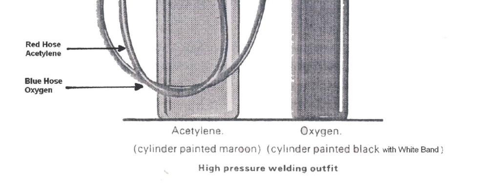
22 4.3 Welding Equipment Acetylene supply in cylinders (painted maroon) or pipeline. Oxygen supply in cylinders (painted black with white band/pipeline). Acetylene pressure regulator. Oxygen pressure regulator. Flashback arrestor, oxygen and acetylene. Blowpipe with a range of nozzles. Two lengths of gas hose, red for acetylene, blue for oxygen. To conform with international standards (ISO). Each hose fitted with saffire hose check valve and regulator connecting nut. Set of spanners and a cylinder valve spindle key for each cylinder. Welding goggles and a spark-lighter. Welding rods and fluxes. Cylinder trolley or cylinder stands. Note: All the above equipment is available from BOC. 12

23 Figure 6. 13
24 4.4 Gas Cylinders Many gases are considered harmless at normal atmospheric pressure and temperature. However, if they are subjected to high pressure or temperature changes they are potentially hazardous. A good example is air; it is perfectly safe until pressurized, when its stored energy can make it hazardous. Cylinders used for storing gases under pressure are designed and built to a high specification and are subjected to regular pressure tests. The supplier of the gas in the cylinder has a legal duty under the Pressure Systems and Transportable Gas Containers Regulations 1989 to inspect and test the cylinder regularly. How often the cylinder needs to be tested will depend on: The gas contained in the cylinder fuel gas cylinders are tested more frequently than compressed air cylinders for example. The working pressure the cylinder is subjected to different gases are stored at different pressures. The supplier can establish when the cylinder is due for test from stampings on the neck of the cylinder and by using shaped and coloured test rings fitted around the neck of the cylinder. Each colour and shape of the test ring will determine in which year the test is to be carried out. This test ring is for the suppliers use and need not concern the users of the cylinder. Cylinders are filled to different pressures dependent on the characteristics of the gas and the capability of the cylinder. They are made of steel or aluminium alloys. All cylinders are manufactured to meet European and British Standards and / or Home Office Specifications. Although some cylinders are welded most are solid drawn from a single steel billet. This gives them strength and robustness. 14
25 In addition some cylinders have bursting disc to vent the gas quickly and reduce pressure should the cylinder be subjected to heat for example. Most cylinders do not have a bursting disc. If the pressure increases abnormally, the cylinder normally splits or peels open to release its contents rather than fragmenting. However, it does depend on circumstances and the reasons for failure. The golden rules of cylinder safety are: Never tamper with cylinders Never re-paint, change markings or identification or interfere with threads Never disguise damage to a cylinder or valve. Contact the supplier Never attempt to repair a cylinder Never mix gases in a cylinder Never transfer or decant gas from one cylinder to another Never scrap a cylinder you do not own Never subject cylinders to abnormally high or low temperatures Never try to refill a cylinder Never use them as rollers or supports Never pick them up by magnetic lifting 4.5 Gas Cylinders A portable steel container for storing and transporting industrial gases, such as compressed oxygen or dissolved acetylene. The steel cylinders are painted black with a white band on top; the usual sizes are 120ft³, 180ft³ and 240ft³. 15
26 The pressure of the gas in the cylinder is potentially the greatest hazard: Mild steel cylinders are charged to pressure of 1980 lb/in² Alloy steel cylinders to 2500 lb/in² Operating pressure readings on gauges: Oxygen 30 lb/in² Valve Socket RH Thread Valve Spindle Oxygen Cylinder Coloured Black White Top Oxygen right-hand threads (turn clockwise). 4.6 Acetylene Cylinders Cylinders of varying sizes are used to transport acetylene. The acetylene cylinder is made of steel with a concave bottom, which is protected from wear by a welded steel band. The illustration shows a cutaway view of a standard acetylene cylinder. After the acetylene cylinder is built, a wet cement mixture of various 16
27 materials, such as asbestos or charcoal, is packed into the cylinder. The cylinder is then baked, and the mixture forms a porous, sponge-like mass. Under pressure, dissolved acetylene is safe, but free acetylene over 15 psi pressure is unsafe. For safety, then, it becomes necessary to dissolve the acetylene. Acetone initially dissolves about 25 times its own volume, and as the temperature increases, so doss the amount of absorption. About 40% of the cylinder volume is filled with acetone, and, as the cylinder is charged with acetylene, the acetone absorbs the acetylene and swells up in the porous material. The acetylene cylinder can be charged to 250 psi. In each cylinder are fuse plugs, consisting of steel bolts tapped into the cylinders. These are drilled and filled with a low melting alloy that melts between 203 and 207 F. In case of fire, the gas escapes through the melted fuse plugs, so a torch flame should be kept away from all cylinders. Most fuse plugs are on the top and/or bottom of the cylinder. The cylinder should always be placed upright during use since the liquid acetone can run through the regulators and into the hoses if the tank were placed on its side. Cylinders are charged to pressure of 225 lb/in² Operating pressure is 15 lb/in² 4.7 Summery - Acetylene C2 H2 (dissolved) Produced from: Cylinder Colour: Characteristics: Odour: Calcium carbide and water Maroon Colourless Garlic like Specific Gravity: Lighter than Air: 0.9 (air = 1) 17
28 Inside the cylinder is a porous mass known as Kapok or Charcoal. Its purpose is to break up the internal volume of the cylinder into a number of small compartments. This is a safety precaution because should the acetylene start to decompose or become unstable within the cylinder, it is impossible for the reaction to spread throughout the whole mass. Figure 7. 18
29 5.0 Identification, Care and Storage of Gas Cylinders Cylinders containing gases are manufactured user strict government regulations. A colour code (B.S.349:1932) is used to indicate the contents of each cylinder. Colour Black with White Band Maroon Red Dark Grey with Black Neck Grey Gas Oxygen Acetylene Coal gas and Hydrogen Nitrogen Air To prevent the interchange of fittings between cylinders containing acetylene and oxygen gases, the valve outlets on acetylene gas cylinders are screwed left-handed and they will have a groove cut around the circumference as shown. Figure 8: Left-Hand Thread Combustible Gas i.e. Acetylene Figure 9: Right-Hand Thread Non-Combustible Oxygen 19
30 5.1 Safe Storage of Gas Cylinders Oxygen and acetylene cylinders should never be stored together. They should be stacked as in the diagram, with the bottom layer well chocked to prevent rolling, or stored upright with a securing chain to prevent them falling over. The full cylinders should be stored separately from empty ones and used up in rotation as received. The storage area should be cool and dry, protected from direct sunlight, frost, rain and corrosive conditions. There should be prominent signs indicating the presence of fire risk and No Smoking signs should be strictly observed. Cylinders should never be handled roughly or allowed to fall from a height. When using cranes, etc., to lift cylinders, a protective mat or cradle should be used. Cylinders should never be used as rollers. If a cylinder has been damaged in any way it should be labelled accordingly, and the suppliers should be notified when it is collected. When moving cylinders that are in use and have regulator valves attached use a proper trolley. The cylinder valves should be turned off, using the correct key, before the cylinders are moved, and care must be taken to protect the regulators from knocks and bangs. 20

31 5.2 Acetylene Cylinders in Fire Acetylene becomes unstable as pressure increases so acetylene cylinders involved in a fire can be extra dangerous. After the fire is extinguished treat any acetylene cylinders as follows: Figure 11. Other Cylinders Spray with water from a safe position and keep checking until steaming from the cylinder surface stops. Contact BOC Gases regarding disposal and removal of cylinders. If safe to do so remove the cylinder to a safe position outside. 21
 and use of")
32 5.3 Labelling All cylinders must carry a label. The label is the only sure means of identifying the gas inside the cylinder. It may also give the pressure the gas is stored at and outline basic safety requirements in accordance with the Carriage of Dangerous Goods (Classification, Packaging and labeling) and use of Transportable Pressure Receptacles Regulations 1996, and the Chemical (Hazard information and Packaging) Regulations The label should be complete and be attached to the cylinder. Always check the cylinder is correctly labeled before use that its contents can be positively identified. Figures 12, 13: Labelling 22
 23 Vehicle Body Repair phase 2 Revision 2.")
33 Industrial Gas Cylinders Identification (the numbers shown correspond to colours in British Standard 381C) 23 Vehicle Body Repair phase 2 Revision 2.0 January 2014
34 5.4 Regulators The pressure of the gases obtained from cylinders is much higher than the gas pressure used to operate the welding torch. Since the pressure of the gases must be reduced between the cylinder and the welding torch, special reducing valves called regulators are required. Regulators are precision instruments containing machined components which need to be handled with care. Avoid rough treatment which could damage sensitive springs, diaphragms, valve seals, safety valves etc. Most regulators are constructed with two gauges. One gauge shows the pressure (amount) of gas being delivered to the torch. Regulators are being manufactured to new European (EN) Standards. BS EN ISO 2503: 1998 sets out the standard for design and testing of regulators operating at pressures of up to 300 bar. The pressure of gas in an oxygen cylinder is 19801b/in² and the pressure of gas in an acetylene cylinder is 2251b/in² Pressure readings on gauges are up to: Oxygen 301b/in² Acetylene 151b/in² 24
35 5.5 Automatic Pressure Regulators These are fitted to the oxygen and acetylene cylinders to reduce the pressure and control the flow of the welding gases. They are fitted with two pressure gauges. One indicating the gas pressure in the cylinder, and the other indicating the reduced outlet pressure. Figure 14: Acetylene Pressure Regulator Figure 15: Oxygen Pressure Regulator 25
36 5.6 Pressure Regulators Figure 16 Always treat a pressure regulator as a precision instrument. Do not expose it to knocks, jars or sudden pressure surges caused by the rapid opening of the cylinder valve. Always open the cylinder valve slowly and smoothly using the special Spindle Key. Periodically check the bullnose seating on the pressure regulator. If the seating is damaged, it will leak gas. The pressure regulator should be replaced immediately. Never use a pressure regulator with other than the gas for which it was designed. Release pressure using the pressure adjustment screw when shutting down, after cylinder valves have been closed and pressure in the hose has been released. If gauge pointers do not return to zero when the pressure is released, the mechanism is faulty and the regulator should be replaced. If the regulator "creeps" (passes gas when the pressure adjustment screw is released, or builds up on the low pressure side when the blowpipe valve is shut) it should be replaced. Ask for details of the BOC Service Exchange Scheme for safety and economy. Do not attempt to repair regulators. 26
37 5.7 Flashback Arrestors Figure 17. Flashback arrestors are fitted to the regulators on both the oxygen and acetylene cylinders. The purpose of these is to prevent flames getting back into the cylinders in the event of a backfire or similar accident. There are two types of flashback arrestors - a disposable type and a re-settable type. 5.8 Hoses These carry the gases from the regulators to the blowpipe. They are rubber, backed with canvas reinforcement. The oxygen hose is blue in colour with right-hand threads on all connections. The acetylene hose is red with left-hand threads on all connectors. One end of the hose is connected to the flashback arrestor at the cylinder end, while the other end is connected to a hose check valve at the welding blowpipe end. 27
38 The correct hose bore size, pressure rating, length and colour coding are essential for safety. European Standard BS EN 559 (formerly BS 5120) sets the requirements for the manufacture of hoses, including their colour for different gases: Blue Red Black - Oxygen - Acetylene and other fuel gases (except LPG) - Inert and non-combustible gases Orange - Liquified Petroleum Gases Never use hoses that are longer than necessary. Never use equipment while hoses are wrapped around the cylinders or trolley 5.9 Hose Check Valves Hose check valves, or hose protectors, are fitted between welding blowpipe and the hoses. They are marked "fit to blowpipe" or with a directional arrow to ensure that they cannot be fitted incorrectly. Should they be fitted incorrectly, i.e. attached to the regulator, no gas will flow through them. Basically they are spring loaded nonreturn valves designed to close in the event of a backfire taking place in the welding blowpipe. 6.0 High Pressure Blowpipe This is designed to mix the gases and deliver them to the nozzle. As the two gases delivered to the blowpipe at equal pressure the injection principle as used in the low pressure blowpipe is unsuitable for us on the high pressure system. There are several makes of gas welding blowpipes on the market all of which are 28

39 supplied with detachable nozzles of different sizes. These numbered nozzles indicate the approximate consumption of gas in litres per hour. Usually they are numbered etc. The greater the number the larger the hole size. Therefore the larger the nozzle the greater the amount of heat can be achieved. The blowpipe is simply a mixing device to supply approximately equal volumes of oxygen and acetylene to the nozzle, and is fitted with regulating valves to vary the pressure of the gas, as required. 6.1 Ancillary Equipment A spindle or bottle key is used to open the valves on both cylinders. Each valve should only be opened approximately ½ turn and during use the key should be left in the position on the acetylene cylinder, so that it can be turned off immediately in the event of an emergency. Spark lighters are used to ignite the gases. Do not use matches or cigarette lighters as these could constitute a hazard. 29
40 6.2 Flash Back This is the appearance of a frame beyond the blowpipe and even into the regulator. Back fire This is the appearance of a flame in the neck or body of the blowpipe. Back Fire may occur when there is: A dirty nozzle tip Wrong pressure for nozzle being used Touching plate or weld pool with nozzle Overheating of blowpipe (cool down in water. Make sure that the gas is passing through nozzle) 30
41 6.3 Blowpipes for Special Purpose The use of blowpipes for cutting is, in the main, restricted to the cutting of ferrous materials, as the process is one of oxidizing the metal. It is also possible to cut stainless steel by feeding iron powder into the flame, but this requires the use of a powder hopper and compressed air system, in addition to an attachment which fits on the head of a cutting blowpipe. Other means for cutting stainless have, in the main, superseded this method and the equipment is no longer generally available in the UK. Steel mills prepare billets by scarfing the surface of the material prior to rolling. This requires the use of a special blowpipe designed to produce high flows of oxygen at low pressure, similar in many respects to flame gouging. To enable quick starts to be made a mechanism to feed a mild steel rod into the flame is an integral part of these blowpipes. Due to the low demand, they are not generally available in the UK and have to be imported. 6.4 Blowpipes High-pressure blowpipes for use with dissolved acetylene are of the mixer pattern. Both gases must be supplied to the blowpipe at pressures appropriate for the blowpipe nozzle. Figure 18 31
42 Figure 19 32
43 6.5 Nozzle Size and Gas Velocity The power of the blowpipe is measured by the amount of acetylene gas that is used per hour. Blowpipe manufacturers have various ways of showing this: By the quantity of gas passed per hour, in litres. By the diameter of the hole in the nozzle. By a number corresponding to the plate thickness that can be welded by that nozzle. It is most important when making a weld that the correct blowpipe power is used. The two factors that mostly affect this are the velocity and quantity of gas which passes through the nozzle. The capacity of a nozzle (the power) is recognised by the amount of acetylene it consumes per hour at the recommended gas pressures: this is usually expressed in cubic feet or litres. Manufacturers usually mark their nozzles with a number, indicating the capacity in cubic feet or litres. Always check the manufacturer's recommended flame setting for specific nozzles. For any metal, and welding technique employed, the flame required has a definite relationship to the type of metal and thickness. PLATE THICKNESS NOZZLE SIZE INCHES MM FT3 LITRES 1/ / / / / / /
44 6.6 Nozzle Maintenance Do not maltreat a nozzle. Do not use it as a hammer or lever. To clean nozzle orifices, sets of special nozzle cleaning reamers are available form BOC. Should these not be available use a drill one size smaller than the orifice and work it up and down without twisting; the drill should be held in a pin vice. If the drill does not enter easily start with a smaller drill increasing in size until the correct diameter is attained. Effective preheat shape can only be maintained if gas orifices are sharp and square with the end of the nozzle. If the nozzle becomes damaged on the end, rub it down with a sheet of fine emery laid on a flat surface such as a sheet of glass taking care to keep the nozzle square with the rubbing surface. The orifice should then be cleaned out as described above. The nozzle has been designed to make this reconditioning possible and as much as 3mm (⅛) may be removed before a nozzle becomes unserviceable. Figure 20, 21: Nozzle cleaning 34

45 6.7 Connections to Cylinders Figure 22 Gas supply may be from separate cylinders secured to a rack, workbench or mobile trolley, or piped to the welding station from an evaporator or cylinders linked by manifolds. Figure 23 35
46 Manifold system of distributing gases At the welding station (or at the cylinders) the high-pressure gases are passed through regulators to reduce to correct working pressure. Usually these regulators are screwed into the cylinder outlet valves. Regulators may be fitted with gauges on the highpressure side to indicate cylinder gas pressure, and on the lowpressure side to indicate the gas-flow pressure. Note: Copper pipe is never used for acetylene. 6.8 Fitting of New Cylinders When you are fitting new cylinders you should remember the following safety points. Keep eyes clear when cracking snifting cylinders Do Not Smoke Crack acetylene cylinder outside if possible Use open spanner (Do not over tighten) Blow out hoses before connecting up Turn cylinder key half turn Report any leeks to your instructor Rectify leaks immediately Figure 24: Cylinder Key 36
47 6.9 Operator Safety The cylinder valve is a safety mechanism, if dirt, grit, oil or dirty water gets into the cylinder, the valve may leak. It is extremely dangerous to attempt to repair cylinder valves. Never apply any form of lubrication or sealing compounds to threads. Any fittings and equipment used must be fit for its purpose and suitable for the gas in the cylinder. Never apply PTFE tape, jointing compounds or any other sealing materials to the valve in an attempt to achieve a gas tight seal. If a gas tight seal cannot be achieved metal to metal, replace the regulator or change the cylinder. Note: some regulator bullnose connections have O ring seals. Check these are in a good condition. If not replace with an approved part, remove the plastic protection caps. The cylinder valve or pipeline valve should be inspected for damage prior to opening Snifting Before fitting equipment to cylinder valves make sure there are no particles of dirt or water in the valve outlet. snifting is the term used to describe the means of removing fine particles of dirt and moisture from the cylinder valve outlet. Under no circumstances use sharp objects like screw drivers to clean cylinder valve seals. Eye protection and gloves must be worn during snifting. Do not look into the cylinder valve while snifting 37

48 Visually inspect the valve for damage, check the threads are clear and use a clean dry cloth to remove any large deposits. Fit the spindle key to the valve. Stand clear of the gas stream and on no account deflect the gas stream with your hand. Hold the cylinder securely with one hand and proceed to crack open, then immediately close the valve. There is some noise associated with snifting, this is normal. The extent of the noise will depend on the pressure in the cylinder. When snifting fuel gases ensure there is no possible source of ignition in the vicinity. When snifting inert gases and oxygen ensure there is good ventilation. Never snift hydrogen as it may ignite spontaneously. Never snift toxic or corrosive gases. Instead carefully inspect the outlet and if there are any signs of dirt, blow it out with a jet of oil free compressed air or nitrogen. Figure 25 38
49 6.11 Fitting of New Cylinders 1. Blow out the cylinder valve socket by opening the valve about a ¼ turn. Close immediately. This is called cracking open the cylinder valve Figure Make sure valve socket is clean before screwing the regulator into the valve socket. Tap spanner sharply to ensure a gastight seal. Figure Slacken the regulator pressure control screw so that there is no pressure on the gauge. Figure 28 39

50 Connecting to the Cylinder Connect the regulator to the cylinder valve (left hand for acetylene and other combustible gases, right hand for oxygen and other noncombustible gases), using the correct spanner and ensure a gas tight seal. Do not use any form of jointing paste or tape between regulator and cylinder valve. Check that the pressure adjusting screw of the regulator is fully released (turned fully anti-clockwise). Commencing Operation Connect the downstream equipment and open the cylinder valve slowly. Check all joints for leaks using a 0.5% Teepol in water solution. The contents of the cylinder will register on the cylinder contents gauge and will decrease to zero as the cylinder empties. The contents are generally shown in the bars and Ibf/in² (1 bar = 14.5 Ibf/in²). To set pressure, screw the pressure adjusting knob clockwise until the required outlet pressure registers on the outlet gauge. When gas is flowing, there maybe a reduction in pressure, and adjustments should be made. Purge the gas line before lighting the equipment. Finish of Operation When work has stopped, close the cylinder valve, vent gas from the system and unscrew the pressure adjusting knob. Check for Leaks and Rectify Immediately 40

51 6.12 The Welding Flame The following procedures should be followed when lighting and adjusting the blowpipe flame. 1. Open all the blowpipe valves. 2. Open cylinder valves slowly by one turn of the spindle. 3. Set the regulators to the correct working pressure. Close blow pipe valves. 4. Open the acetylene control valve on the blow pipe about ½ - ¾ of a turn. 5. Using a pilot light or spark lighter, light the acetylene. (Ensure that the flame points away from you). 6. Reduce or increase the gas supply by operating the blow pipe valve until the flame just ceases to smoke. 7. Open the oxygen control valve on the blow pipe until the white inner cone in the flame is clearly visible. THIS IS THE CORRECT FLAME FOR WELDING MILD STEEL. 8. To extinguish the flame, close the acetylene valve and then the oxygen valve on the blow pipe. 41
52 6.13 The Oxy-Acetylene Flame Acetylene is composed of Hydrogen and Carbon, as are most fuel gases. It is mainly the carbon which provides the intense heat and very high flame temperature (3100 C) when burned with oxygen. If sufficient oxygen is not provided, then the carbon is given off into the air as black, sooty smuts. Acetylene has a very high proportion of carbon in it and if the oxygen is turned down to provide a flame with excess carbon; the carbon is taken into the steel to provide a high carbon surface, used for hard surfacing operations. A neutral oxy-acetylene flame burns equal proportions of oxygen and acetylene and is reducing in nature, thereby reducing any iron oxide to iron and taking up the oxygen; consequently there is no need to use a flux when welding steel. It should be noted that iron oxide is not refractory. Figure 29: The Oxy-Acetylene Flame Showing the Various Zones. 42
53 6.14 Welding Demonstration 2 The Structure of the Oxy-Acetylene Flame AIM: To demonstrate the three oxy-acetylene flame settings. EQUIPMENT: Oxy-acetylene welding equipment, including goggles and flint lighter. THEORY: There are three distinct flame settings: 1. Neutral Flame This flame burns equal quantities of oxygen and acetylene. (In practice, it is advisable to have the slightest possible acetylene haze at the cone tip to begin with.) Figure 30: Neutral Flame Cone tip hottest part approx C. 43
54 2. Carburising Flame This flame has an excess of acetylene which results in a carbon- rich zone extending around and beyond the cone. Note: Both the Neutral and carburising flames are reducing in nature. Figure 31: Carburising Flame 3. Oxidising Flame This flame has an excess of oxygen which results in an oxygen-rich zone just beyond the cone. This flame is obtained by setting to neutral and then turning the fuel gas down. Figure 32: Oxidising Flame 44
55 Safety With Industrial Gases 45
56 6.15 Operator Safety Daily Check List for Gas Control Equipment: Leaks may develop in any part of a gas system but particularly at joints. It is important that all equipment is checked using an approved leak detecting solution and if necessary corrective action taken before use. Always check that each cylinder is labelled correctly identifying Gas and Pressures. Before work, check that the gas cylinders are stored in an upright position and secured. Inspect pressure regulators for danger. Always use a regulator which is designed for the gas and pressure you are using (e.g. 230 bar regulator on new 230 bar cylinder). Never use an oxygen regulator for nitrogen or air. Regulators must be labelled to BS 5741/BS Inspect the condition of hoses for signs of deterioration. Always use hoses of the correct colour and quality blue for oxygen, red for acetylene, orange for propane and black for inert gases. Hoses must be marked/labeled to BS 5120 Ensure flashback arrestors are fitted to both oxygen and fuel gas systems. They must be labelled correctly for the gas and pressure being used, labelled to BS Ensure hose check valves are fitted to hoses at the torch end. Ensure there are no solvents, oil or grease present as high pressure oxygen reacts violently with these substances and may explode or ignite. Ensure there are no jointing compounds, lubricants or thread tape on any gas fittings or connections. 46
57 Check all connections on hoses are crimp fittings. Check that both hoses are equal length. Do not coil surplus hose around the cylinders or regulators. Set the correct gas working pressure and leak test all parts of the work station equipment using an approved leak detecting solution. (Diluted Teepol solution) Before lighting up ensure both hoses are correctly purged. Check that suitable fire precautions are taken and fire extinguishers are available. Always have BOC data and safety sheets for each of the gases used and stored on your premises. Safety BOC supplies equipment which is manufactured to the highest standards of quality and safety and will give first-class service for many years if operated correctly. The following notes will help to ensure your equipment is efficient and safe. Some suggestions for personal safety are also included. It is not intended to list every possible safeguard. These notes must be supplemented by caution and common sense on the part of the individual. Remember familiarity breeds over-confidence. Safety precautions to be observed when using compressed gases with welding and cutting equipment are described in the companion booklet, "Safe Under Pressure" available from your nearest BOC branch or Cylinder Centre. Data Sheets and a Cylinder Identification Wall Chart are also available. 47
58 Gas Cylinders Leakage around the spindle of the cylinder valve will be revealed by hissing and in the case of fuel gases, by a smell. Tighten the gland nut on the cylinder valve slightly with a spanner (clockwise) and test with 1 % solution of Teepol HB7 in water. If still leaking, do not use the cylinder but label and return it. If the cylinder is owned by BOC, BOC will carry out an examination and replace it. Never use a Flame when Testing for Leaks Figure 34 48
59 When faced with an industrial gas cylinder full of gas and asked the question what makes the cylinder potentially hazardous? the average person is likely to mention: The size and weight of the cylinder. They can fall over. The gas inside the cylinder. Most people would not think to add: The pressure of the gas in the cylinder PTFE Tape and Oxygen Service In the past there has been some confusion over the use of PTFE tape on equipment used in oxygen service. The subject is quite a complex one but it is hoped that this explanation will clarify the issue. PTFE tape is used in a variety of applications for sealing gas and liquid pipework and is available in various grades, differing in purity, thickness and width. Some grades of tape contain a large proportion of material other than PTFE, and may be lubricated with hydrocarbon based oils and greases. If these grades of tape come in contact with high pressure oxygen there is a chance that an ignition will occur with risk of injury to the operator and damage to equipment. Pure PTFE tape can be, and is, used for sealing components in oxygen service provided it is lubricant-free. Even then it should be applied with care by experienced personnel to ensure that loose strands are not exposed to high velocity gas streams thus. Thus oxygen cylinders and regulators prepared by or for BOC do have PTFE tape on them but only for certain applications and used only in accordance with strictly controlled procedures. 49
60 Because of the possibility of ignition if a low grade of PTFE tape is used or if tape is incorrectly applied, BOC does not recommend its use by customers for oxygen service. In particular the practice of using PTFE tape to form a seal between the oxygen cylinder valve outlet and regulator can be especially high risk. If you experience difficulty in producing an effective seal without the use of PTFE tape, the surfaces of the valve outlet and regulator bullnose should be examined for damage and then refer any problems to supply branch or Gas and Gear Centre. Figure 35 Never Lubricate Regulators. Oxygen equipment is specifically degreased in manufacture. Equipment should not be handled with oily or greasy hands, gloves or rags. 50
.")
61 Make certain that cylinders are well fastened in position so that they will not fall. Fit a cylinder key to each cylinder valve spindle and ensure that it is in the closed position (turned fully clockwise). The spindle key should remain in the valve the whole time the equipment is in use in case there is a requirement to shut off the gas supply in an emergency. Never force connections that do not fit! 1. Right-hand screw thread for oxygen and other noncombustible gases (black Hose). 2. Left-hand screw thread for acetylene and other combustible gases (red hose) Never drop or abuse cylinders! Figures 36, 37,
62 Do not light one torch from another! Do not use a cigarette lighter to light torch! Use a flint lighter to light your torch. Be extra careful to avoid burns. Do not use a match to light your torch. Figure: 39, 40, 41 52
63 Keep empty and filled cylinders separate. Mark empty cylinders. Check system for leaks. These can be detected by feel and by smell or by painting an approved solution into the connections. Be sure that all connections between regulators, adaptors and valves are gas tight. Rectify leaks immediately! Figure 42, 43, 44 53

64 Protect hoses and cylinders from flying sparks, hot slag, hot objects and open flame. Never allow the hoses to come into contact with oil or grease as these will damage the rubber. Ensure hoses are not wrapped around the trolley. Hose protector: this device which is fitted at the blowpipe of the hoses arrests any flame caused by backfire at the inlet connection of the blowpipe. Figure 45, 46, 47 54
65 7.0 Safety Precautions - Welding Before starting to weld, using the oxyacetylene torch, there are a number of safety precautions you should study and remember. Figure 48: Never weld where there is an inflammable material in the vicinity. Figure 49: Never weld on containers (like a petrol can) which have held combustible materials. 55

66 8.0 Hazards 8.1 Oxygen Oxygen cylinders and the fittings attached to them must never be greased or oiled. Even small quantities of oil and grease, when mixed with oxygen, can react and cause an explosion. Oxygen has no smell and does not burn, but it will support and speed up combustion. It should never be used for ventilating enclosed spaces or for blowing clothes or other combustible material. Even a spark can, under these conditions, start a fire which may result in considerable damage or injury to personnel. 8.2 Acetylene Acetylene gas has a noticeable smell, is highly inflammable and will ignite and burn very easily. Even a mixture of acetylene and air as low as 2% will give an explosive compound condition when in contact with metals and alloys, such as those containing copper and silver. Piping s and fittings made of copper should never be used with acetylene gas. Take extra care with both oxygen and acetylene cylinders to ensure that there are no leakages when assembling the equipment. Dirt should be blown clear of the valve seats by cracking the valves momentarily before attaching the pressure regulator. Figure 50, 51 NEVER: test for leakage with a flame. Soapy water should be brushed over the joint to test for leakage of gas. Always check, on completion of the job that no glowing fragments or sparks are left. 56
67 REMEMBER: that even at some distance away from the oxyacetylene flame the temperature is still very high and capable of starting a fire. Figure 52 Do not use oil based detergent in the testing of leaks. 57
68 8.3 Dangers of Welding in Confined Spaces When welding, fumes are given off which are dangerous to the health of the welder. It is therefore important to remove and dispose these fumes. This is particularly important when welding in confined spaces, such as inside boilers, tanks, ships compartments, etc. When welding in confined spaces it is necessary to use some form of mechanical ventilation. This usually consists of an elongated hood attached to a flexible ducting, connected to an extraction fan. It is necessary to arrange the hood in such a position that it draws air across the face of the welder towards the welding. Forced ventilation not only reduces the fumes but also lowers the temperature in which the welder is working and increases his comfort. The fumes from welding consist of iron oxide particles which, when inhaled, will remain in the lungs causing damage to them. Arcing can also result in nitrous fumes (oxides of nitrogen) being formed. These give little warning of their presence and can cause serious damage to the lungs. Figures 53, 54 Oxygen should never be used to Ventilate Confined Spaces. 58
69 Fatal accidents through workers' clothes becoming ignited have resulted from this practice. The use of compressed air for forced ventilation is also an undesirable practice. Figure 55 When welding is finished for a long time (during lunch or overnight) close the cylinder valves and then release all gas pressure from the regulators and hoses by opening the torch valves. Close the torch valves and release the pressure adjusting screws. In case of burns or accidents always turn off torch FIRST. Do not fool around with torch flame. Remember to wear goggles at all times when welding. Always blow out hoses before fitting. NEVER joint hoses with copper pipe. 59
70 9.0 Welding Safety Always wear protective clothing, i.e. flame retardant overalls. Always wear the correct eye goggles. Always have the spindle key in the acetylene cylinder valve. Always keep cylinders secured in an upright position. Always check for leaks with a soapy solution, NEVER with a naked flame. Never carry out makeshift repairs on welding equipment. Never weld an enclosed vessel, i.e. petrol/oil drums until they have been thoroughly cleaned. Never work in an enclosed vessel on your own and always leave the cylinders outside. If working in an enclosure vessel, adequate ventilation should be provided and fire fighting equipment should be available. In the event of a serious flashback or backfire plunge the blowpipe in a bucket of cold water, leaving the oxygen running to prevent water entering the blowpipe. Should the hoses become damaged, turn off the supply of gas at the cylinder and inform your supervisor. Don t forget, this equipment, if misused or damaged can be dangerous. If in any doubt seek assistance and clarification form your supervisor. Always have flash back arrestors fitted and hose check valves. To convert Celsius to Fahrenheit use. C = 5/9 (F 32) and F = 9/5 C
71 10.0 Conduction Heat travels along metal objects. The heat given to the object is passed all along until the whole object has a uniform temperature. Heat conductivity varies with materials. Metals are good conductors while materials like asbestos and fibreglass resist the flow of heat. These may be called bad conductors of heat or good insulators. Liquids such as water, petrol and oil are poor conductors of heat and gases are even poorer. Liquids and gases normally transfer their heat by convection which we will consider next Convection When fluid is heated a movement takes place in the fluid. If water at a temperature above 4 C is heated, it expands, decreases in density and rises towards the surface. The same effect happens with other liquids and gases. Water gets hotter, expands, gets lighter and rises Radiation This is heat transfer by rays which are similar to light rays. An example is the sun. The sun's rays are powerful and are capable of travelling through space. In a similar way the heat from any source can be felt when there is no interruption to the path of the rays. This radiant heat consists of invisible electro-magnetic waves which behave in a manner similar to light waves: They travel in a straight line; They can be reflected. 61
72 The rate of heat transfer depends on: Temperature of the source; Area of its source and nature of its surface. The hotter the source, the greater will be the transfer. Increasing the area has the effect of 'spreading out' this hot surface and allows the heat to be given up more readily. The nature of the surface is the finish. A dull dark finish radiates heat better and also absorbs heat better than a highly polished surface The Nature of Heat A substance is made up of tiny particles called molecules and these consist of even smaller particles called atoms. Observations of these tiny particles shows that each one is vibrating; the amount of vibration depending on the 'hotness' of the substance. So: Heat is internal energy and is capable of doing work. Heat flows from a hot to a cold surface. A hot object placed beside a cold surface will cause the heat to 'flow' until the two things are at the same heat. 62
73 14.0 Temperature The temperature of a body is the degree of hotness". This is different to the heat contained in an object, e.g. more energy will be required to heat four litres of water than that to heat two litres to the same temperature. Although terms like 'hot' and 'cold' give an indication of the temperature, they lack accuracy and can lead to misunderstanding, e.g. a hot day means something different to a hot engine. Temperature is measured by a thermometer Celsius Scale Everyday temperature measurement uses this scale which is similar to that introduced in 1742 by the Swedish scientist Andreas Celsius. In this case the freezing point of water is marked 0 C and the boiling point 100 C; temperatures below zero are given negative values. For many years this scale was known as Centigrade but nowadays it is recommended that the name Celsius be used Fahrenheit Scale To convert C to F we use: F = 9/5 (C) + 32 A scale used in Britain until fairly recently. The upper fixed point was marked 212 F and the lower point as 32 F; the interval between divided into 180 degrees. To convert F to C the formula is: C = (F - 32) x 5/ Kelvin Scale The SI unit of temperature is the 'Kelvin'. This has the same size of degree or temperature interval as the Celsius scale, but has a zero about -273 C. To convert from Celsius to Kelvin add
74 14.4 Temperatures Oxy - Acetylene Brazing Below are listed temperatures for some commonly used gases. TYPE OF GAS APPROXIMATE FLAME TEMPERATURE Oxy-acetylene 3200 C Oxy-propane 2500 C Oxy-hydrogen 2200 C Oxy-coal 2000 C You will see from these temperatures that it is very important to use every precaution when the torch is operating. Never pick up hot objects Never do any chipping or grinding without wearing goggles Figure 56, 57 64
75 15.0 Principles of Combustion of Oxygen and Acetylene gases All operators and users of gases in cylinders must fully understand the potential hazards and properties of the gases they are using and are stored on site. Each gas has its own characteristics, which affect its behaviour. Gases also change characteristics when subjected to external pressures. An important characteristic of a gas is its density relative to air because this will determine whether it rises or falls if it leaks. The table below gives the densities of some common gases. Gas Density Compared to Air (Approximately) Hydrogen 0.06 Helium 0.1 Nitrogen 0.9 Acetylene 0.9 Air 1 Oxygen 1.1 Argon 1.4 Carbon dioxide 1.5 Propane 1.5 Most gases are colourless and odourless in their natural state so there is little or no warning of a leak. Most fuel gases have or are given a smell to aid leak detection. All suppliers have a complete range of material safety data sheets which detail the chemical and physical properties of the gases as well as their characteristics. In addition suppliers can provide advice on safe handling, storage, transport and use of the product. 65
76 IMPORTANT: Know all the properties of the gases you deal with. Industrial gases are categorised as follows: Oxidants These do not themselves burn but support combustion. By increasing the amount and type of oxidant many things will burn that are not normally flammable. Examples: Air and Oxygen Inerts These do not generally react with other material, they do not support combustion nor do they support life. Inert gases should be regarded as asphyxiants because if they leak they displace air hence the oxygen in the atmosphere. Examples: Nitrogen, Argoshield and Helium based mixtures. Flammables These gases when mixed with an oxidant and provided with the right ignition source will burn. An increase in the temperature of the fuel/oxidant mix can also cause ignition. Examples: Acetylene, Hydrogen and Propane Toxics These have the potential to cause injury or threaten life, even in small concentrations. Examples: Carbon Monoxide, Chlorine and Ammonia 66
77 Corrosives These react chemically with other materials causing reactions and deterioration. Toxic gases may be given off. Examples: Chlorine and Sulphur Dioxide Pyrophorics Will ignite spontaneously in contact with air. Examples: Silane and Phosphine 15.1 Acetylene A highly combustible gas composed of carbon and hydrogen (C2H2) and used as a fuel gas in oxy-acetylene welding and cutting. When burned with oxygen in the correct proportions, it produces a flame temperature of approximately 3000 C (5400 F) Acetylene has a natural distinctive garlic smell and is stored in maroon cylinders with left hand connections. In addition to being highly flammable it is an asphyxiant. However, being significantly lighter than air, it will rise to the highest levels. The flammable limits in air are approximately 2% to 82%, so it should only be used in well ventilated areas. All equipment must be leak tested with an approved leak test solution prior to use. Acetylene is produced by the chemical reaction of calcium carbide and water. The gas produced, raw acetylene (C2H2) becomes unstable with increasing pressure and is regarded as an explosive at pressures above 0.6 bar (9 psi). Calcium Carbide has the appearance of small grey stones. It belongs to the class of substances known as hydrocarbons. To fill cylinders with sufficient volume at a reasonable working pressure, acetylene must be stored under controlled conditions. The acetylene is dissolved into acetone, which is a liquid. 67
78 15.2 Acetone An inflammable and volatile liquid used as a solvent in acetylene cylinders to dissolve and stabilise acetylene under pressure. Acetone is a spirit with an affinity for acetylene. Under normal atmospheric conditions acetone will dissolve 25 times its own volume of acetylene. Since the acetylene cylinder is charged to 15 atmospheres the acetone is capable of holding 375 times its own volume, i.e. 25 x 15 = 375. To avoid disturbing the acetone when moving the cylinder it is absorbed by the charcoal kapok filling or made of lime silicate. This porous filling is called a monolithic mass and has a structure like concrete with the porosity of a sponge. Acetone fills about half of the available void in the porous mass when the cylinder is first filled. Acetylene gas is dissolved in the acetone which swells in volume as more gas dissolves until, eventually, all the voids are occupied by acetone saturated with acetylene. Without a sponge in the cylinder the acetone would simply settle at the base of the cylinder and gas would form above it. This would be unstable, so the mass holds the liquid and the liquid holds the gas. Since the cylinders contain liquid acetone, they should be moved and transported with their valves uppermost. If an acetylene cylinder has been moved horizontally it must be allowed to stand for not less than an hour before use, to prevent acetone being forced out the valve under pressure of the gas. If this happens the acetone, which is a solvent, can attack the neoprene diaphragms and valve seating in regulators and ancillary equipment and it may be necessary to replace the regulator and or the flashback arrestor hoses etc. 68
79 Acetylene Physical Characteristics Molecular weight Boiling point (1 atm) -84 C Density of gas (15 C at 1 atm) kg/m³ Critical temperature 35.2 C Flammable limits in air (by volume) 2 to 82% Ignition temperature 325 C Specific Gravity (air = 1) Colour Colourless Smell Natural garlic odour Acetylene is not compatible with certain materials. It reacts with silver, mercury and copper to form acetylides which are impact explosives. Anything with a copper content in excess of 70% will form copper acetylene. This is a perfect example of why you should only use equipment for the gases for which it has been designed. Acetylene equipment does not contain items of pure copper. Acetylene gas under excess pressure becomes unstable and is regarded as an explosive. Cylinders must never be subjected to intense heat or physical impact as the rise in temperature and pressure may cause the acetylene to thermally decompose. When this happens, the acetylene molecule, which consists of two carbon and two hydrogen atoms, splits this exothermic chemical reaction generates heat which triggers adjacent molecules to split and so on. The rapid rise in temperature gives a corresponding rapid rise in pressure. Prior to moving a cylinder that has been subjected to heat or severe impact, always check for temperature rise within the cylinder using the back of your bare hands. Despite the decomposition of the gas and the increase in temperature and pressure the cylinder may seem to be in a normal condition. If the cylinder is moved it may detonate and anyone nearby may be fatally wounded by the impact of the blast. 69
80 Never move or approach an acetylene cylinder which has been involved in a fire or has been subjected to heat. Acetylene cylinders are usually fitted with safety devices. (See table below). Theses may be in the form of bursting discs or fusible plugs. They are fitted either in the valve, on the shoulder of the cylinder or in the base of the cylinder. Always ensure that the workplace is well ventilated. With a density of acetylene is lighter than air and may rise and accumulate in roof voids and at high levels. SAFETY DEVICES on CYLINDERS PURPOSE Prevent excess pressure build up as a result of fire or heat damage. Rapidly release contents under adverse conditions. DISSOLVED ACETYLENE Different Types PROPANE Cylinder valve has a bursting disc built-in. Blows off at 82.7 bar (1200psi) Two fusible plugs in the cylinder shoulder. Plugs melt at approx. 100 C Cylinder valve have a built-in pressure relief. Blows off at 25.8 bar (375 psi) OTHERS Oxygen, Nitrogen, Stainshield and Argosheild No pressure relief protection REMEMBER: A cylinder is never empty. It has gas in it at a minimum of atmospheric 70
81 15.3 Oxygen The commercial method of producing oxygen is to abstract it from the atmosphere by a process of distillation. The composition of gases which make up the atmosphere is: Nitrogen 75% Oxygen 23% Other Gases 2% 100% In brief, the air is compressed, causing it to liquefy. In this state the oxygen separates from the nitrogen and can be filtered off. Oxygen does not burn but supports combustion, i.e. it is essential that it is present for combustion to take place. Oxygen cylinders are coloured black and have right-hand threads as does all equipment associated with them. Oxygen cylinders are hollow and when fully charged can be pressurized up to 175 atmospheres or 2,500 1bs/sq² 1 Atmosphere = Kn/M² 150 Atmosphere = 15,195 Kn/M² 175 Atmosphere = 17,727 Kn/M² OXYGEN should never be used as an Air Blow off system. Like most gases oxygen is colourless, odourless and tasteless. It is supplied in black cylinders with right hand connections. Oxygen is often referred to as O2. 71
82 Oxygen makes up approximately 20.9% of the atmosphere we breathe and is essential to life. When we breathe in we inhale: 20.9% Oxygen 78% Nitrogen 1% Argon The remainders being trace gases in very small amounts. When we breathe out we inhale: *16% Oxygen 78% Nitrogen 1% Argon 5% Carbon Dioxide * The reason mouth to mouth resuscitation is so effective Some 5% of the oxygen in the air we breathe is absorbed into the bloodstream with 5% carbon dioxide exhaled as a waste gas. Oxygen is not flammable but readily supports combustion. It is only slightly heavier than air. If a leak occurred the atmosphere around the location could become oxygen enriched. Oxygen enrichment is a real hazard. Always test for leaks using an approved leak detector solution. Do not use soapy water. Materials that readily burn in air, burn much faster and more intensely in oxygen enriched atmospheres. Propane for example will burn when mixed with air at approximately 1900 C; when mixed with oxygen the flame temperature increases to approximately 2900 C to 3200 C. Material not normally considered combustible may burn in atmospheres where the oxygen content is above 20.9% If clothing becomes impregnated with oxygen, ventilate them by walking in fresh open air for at least 15 minutes and avoid going near any sources of ignition. IMPORTANT: High pressure oxygen reacts violently with oils, greases, tarry substances and some solvents. This includes things like soap, butter and some hand creams. 72
. All equipment, valves and cylinders must therefore be kept free from oil and grease.")
83 In some circumstances if oils and greases come into contact with leaking high pressure oxygen the oils may ignite causing very high temperatures and energy release. The energy release is rapid (similar to that of an explosion). All equipment, valves and cylinders must therefore be kept free from oil and grease. Figure 58 WARNING: Always leak test oxygen equipment using an approved leak test solution. Do not use soapy water since this may have an oil base. Only use materials approved for oxygen service. DO NOT use standard PTFE tape or jointing compounds, as these may contain oil. Note: Oxygen compatible PTFE may be used by gas suppliers or equipment manufacturers on fittings. 73
84 15.4 Oxygen Deficiency Most gases used in industry are colourless, odourless and tasteless. Many will not support life and cannot be inhaled on their own, for example: Argon Helium Nitrogen Carbon dioxide Propane These gases are asphyxiants and if released into poorly ventilated areas they will quickly displace the air present and thus reduce the oxygen content leading to oxygen deficiency. Argon and Helium mixtures like Argoshield are also considered as inert gases and may cause asphyxiation. Always ensure that the workplace is well ventilated and test for leaks using an approved test solution. Human beings vary considerably in their reactions to oxygen deficiency. A general indication of what is liable to happen is illustrated in the table below. Oxygen Content (% volume falling) Effects and Symptoms (at atmospheric pressure) Increasing pulse rate, tiredness Physical movements and intellectual performance becomes difficult Possibility of headaches, dizziness and fainting after a fairly short period of time. 6-8 Fainting within a few minutes, resuscitation possible if carried out immediately. 0-6 Fainting almost immediately, death or severe brain damage. In general, oxygen deficiency leads to: - Loss of mental alertness - Distortion of judgment and performance. This happens within a relatively short time, without the person s knowledge and without prior warning. 74
85 It can take as little as two breaths in an oxygen deficient atmosphere to cause unconsciousness. Death occurs within minutes. Work spaces should be well ventilated. Since many of the gases we use are slightly heavier than air and will accumulate at low levels it may be necessary to use forced ventilation. If operators are working in a confined or poorly ventilated area then it is advisable that they carry portable oxygen analysers and adopt the buddy system. This is where one worker in guaranteed fresh air ensures the safety of the other. All operators should be trained in emergency procedures. Oxygen Physical Characteristics Molecular weight 32 Melting point -219 C Boiling point -183 C Critical temperature -118 C Specific Gravity (air = 1) 1.1 Colour Colourless Smell None 75
86 SUMMARY OXYGEN O2 Produced from: Atmospheric Distillation -Air Separation Cylinders: Colour Black Connections: Right hand Specific Gravity: Heavier than Air: 1.1 (Air = 1) Characteristics: Colourless and Odourless. Supports combustion Beware of enriched and deficient oxygen atmospheres. Reacts violently with OIL/GREASE and SOLVENTS. Test for leaks with approved Leak Detection Fluid only. 76
87 16.0 Types of Flux and their Function 16.1 Fluxes The function of a flux is to remove oxides and tarnish from the metal to be joined so that the solder will flow, penetrate and bond to the metal surface, forming a good strong soldering joint. The hotter the metal, the more rapidly the oxide film forms. Without the chemical action of the flux on the metal the solder would not tin the surface, and the joint would be weak and unreliable. As well as cleaning the metal, flux also ensures that no further oxidation from the atmosphere which could be harmful to the joint takes place during soldering, as this would restrict the flow of soldering. Generally, soft soldering fluxes are divided into two main classes: corrosive fluxes and non-corrosive fluxes. Corrosive fluxes These are usually based on an acid preparation, which gives the fluxes their corrosive effect. They are very effective in joining most metals. If the flux is not completely removed after use, corrosion is set up in and around the joint, and the risk of this happening prevents the use of these fluxes in electrical trades and food industries. The following substances are corrosive fluxes: Zinc Chloride (killed spirits) This is made by dissolving pure zinc in hydrochloric acid until no more zinc will dissolve in the acid. This changes the acid into zinc chloride hence the name killed spirits. As an all-round flux for soft soldering zinc chloride is without equal, but it has one disadvantage for some purposes its corrosive action if the joint is not afterwards cleaned thoroughly with water. 77
88 Hydrochloric Acid Although hydrochloric acid is not a good substitute for zinc chloride, it is nevertheless used with excellent results on zinc and galvanized iron. It can be used neat, but it is better to dilute it with at least 50 per cent zinc chloride. Ammonium Chloride (salammoniac) This may be used as a solution in water in much the same way as zinc chloride, but is not quite so effective for cleaning metal. Phosphoric Acid This is effective as a flux for stainless steel, copper and brass, and does not have the corrosive effect of other acidic types of flux. Non-corrosive fluxes These prevent oxidation on a clean or bright metallic surface during soldering. In general non-corrosive fluxes are not so active in cleaning the metal. 78
89 17.0 Weld Symbols on Drawings Engineering drawings are descriptions of manufactured objects in terms of shape, surface, finish and material. In many industries it is customary to draw the shape of the component without indicating how that shape is achieved. The drawing is a description of a requirement produced by the designer for the instruction of the manufacturer. In theory, the manufacturer knows best how to produce an object with the resources he has. In practice, of course, the designer compromises and produces designs which are capable of production by the techniques of which he is aware. For example, a round hole can be drilled, bored or punched and can be finished by reaming, but whichever method is used, the lines on the drawing are the same and whichever method is used, the material is not changed in its characteristics. A welded joint offers a range of considerations which do not arise in other forms of manufacture. Firstly, there are far more techniques for making a welded joint than in many other manufacturing operations. This means that the designer has far less chance of foreseeing the manufacturer's methods. Secondly, the properties and integrity of the joint will depend on the manner in which the weld is made. Despite this, the designer can still indicate the type of joint he requires, provided that he is prepared to accept that he may not be able to completely define the joint in the earlier stages of a design. In some industries it is customary for the manufacturer to produce shop drawings which contain details of weld preparations and reference to established welding procedures not shown in detail on the designer's drawings. The range of British Standard symbols which can be used on a drawing to indicate a weld detail are described here. 79
90 Figure 59: Weld Symbols In practice, the two symbols shown in figure 59 would be used as follows: Figure 60: Use of Weld Symbols Note: The arrow points towards the prepared edge. 80
91 Fillet Square butt Single-V butt Double-V butt Single-bevel butt Double-bevel butt Single-J butt Double-J butt Sealing run Backing strip Dressed flush And a very useful symbol. Full penetration butt weld by a welding procedure to be agreed. 81
92 The weld symbol is always drawn the same way round regardless of the layout of the arrow and the reference line. The position of the symbol on the reference line has significance. A symbol below the reference lien means that the weld is made from that side of the joint indicated by the arrow. A symbol above the reference line means that the weld is made from the opposite side of the joint to the arrow. Figure 61: Weld Symbol Positions Figure 62: Position of the Arrow Note: The arrow points towards the prepared edge. 82
93 Figure 63: Weld All Round A joint made from both sides has a symbol on each side of the reference line. Figure 64: Joint made from Both Sides 83
94 Weld size can be indicated on the symbol, 6mm fillet weld. The drawing must state whether a throat or leg dimension is quoted. Unequal leg fillet weld. This must be defined by leg length. A diagram of weld shape is required here. A diagram is not required here because the size of the member indicates the weld orientation. Information other than weld size may be written to the right of the symbol. Figure Intermittent Welds The figure in brackets is the space length. 50 before (100) indicates that the weld is at the beginning. (100) 50 would indicate a space first then a weld although such an arrangement would not represent good practice. 84
95 17.2 Weld Positions 1. Flat (down hand) position. Figure Horizontal position. Figure Overhead Position Figure 68 85
96 4. Vertical Position. Figure Corner Joint (in flat position) Figure T Joint (flat position) Figure 71 86
97 18.0 Common Weld Faults When you first start to weld you will find that you have some defects in the welds. These are explained here with their causes. Defect Uneven Welds Cause Moving the torch along the joint too quickly or slowly, zig-zaging movements not the same. Fused portion not in joint but to one side Not playing the torch over the joint equally at each side. Holes in the joint Holding the flame too long in one place and overheating the metal. Oxide inclusions Not cleaning the base metals (metal being welded) properly before starting. Inclusions will be seen as black specks on the surface of broken welds. Adhesions Not enough heat to one side of a joint or welding speed too high. As a result the weld metal will break clearly from the metal surface on one side. Overheating Moving flame too slowly. 87
98 19.0 Distortion during Welding 19.1 Causes of Distortion Longitudinal Contraction: If a deposit is made on one side of a flat strip thin plate the plate bends upwards as it cools. Figure 72: Longitudinal Distortion Transverse Contraction: If a butt weld is made between two thin plates that are free to move, the plate edges will be drawn together. The plate edges in advance of the weld may scissor or overlap. Figure 73: Transverse Contraction 88
99 Angular Distortion: If a fillet weld is deposited between two plates in a tee joint the angle between the plates will be reduced as the weld cools. Similarly, angular distortion occurs in a butt joint as contraction of the weld metal pulls the plates out of alignment. Angular distortion increases with the number of runs deposited. Figure 74: Angular Distortion Figure 75: Distortion 89
100 19.2 Control of Distortion Design Reduce distortion by using: Minimum number of suitably arranged joints. Readily accessible joints. Correct weld sizes for the strength required. Balanced welding about neutral axis. Figure 76: Effects of Unbalanced Welding About the Neutral Axis Parent Metal Reduce distortion by using: Correct procedure according to type of metal. Deposition technique which ensures minimum heat input. 90
101 Figure 77: Sequence of Welding Fillet Welds on Either Side of a Vertical Member: One Welder 91
102 19.3 Joint Preparation Tack Weld A shallow, temporary weld to hold the two edges of metal to be joined in proper alignment while the weld proper is being made. Tack welding is important particularly for the maintenance of gap and alignment of parts. Tack welds on sheet metal should be short in length but must be sound and sufficient in number to prevent movement of the parts being welded. The distance between tacks should be about 1 ½ (40.0 mm) for sheet metal up to (1.5mm) and about 2 (50.0mm) for sheet metal between (1.5mm) and (5.0mm) thickness. These distances may be doubled for fillet welded T joints. Tack Welding Procedure Tack welds should be on the side to be welded and in the line of the joint. Heat small triangular area with blowpipe to melt the parent metal where the tack weld is required. Add filler metal to molten pool to make a small but sound weld and then remove the flame. Repeat until all tack welds are made making sure that the gap is kept uniform and of the correct size (where a gap is required). Figure 78 92

103 Figure Assembly Procedure Reduce distortion by: Pre-setting or pre-cambering components, to anticipate distortion pulling components into correct alignment. Restraining components with suitable slippage where necessary to control the distortion within prescribed limits. Using effective symmetrical tack welding, to hold components in alignment and maintain root gap. Figure 80: Pre-setting to compensate for Angular Distortion. 93
Trade of Sheet Metalwork. Module 3: Thermal Processes Unit 1: Oxy-acetylene Welding - Introduction Phase 2
 Trade of Sheet Metalwork Module 3: Thermal Processes Unit 1: Oxy-acetylene Welding - Introduction Phase 2 Table of Contents List of Figures... 5 List of Tables... 6 Document Release History... 7 Module
TRADE OF HEAVY VEHICLE MECHANIC
 TRADE OF HEAVY VEHICLE MECHANIC PHASE 2 Module 1 Induction/Customer Care/Bench Fitting/Welding UNIT: 5 Table of Contents Aims and Objectives... 1 Learning Outcome:... 1 Setting up an Oxyacetylene torch...
Cal/OSHA T8 CCR 1536 Cal/OSHA T8 CCR 4799 Cal/OSHA T8 CCR 4845 Cal/OSHA T8 CCR 4848
 Cal/OSHA Gas Systems for Welding GAS WELDING Cal/OSHA T8 CCR 1536 Cal/OSHA T8 CCR 4799 Cal/OSHA T8 CCR 4845 Cal/OSHA T8 CCR 4848 When performing gas welding, the following precautions, work procedures,
TURBO SET 1000 E D $'9 5(9
 TURBO SET 1000 Instructions for use and maintenance HOW TO GAS WELD WITH TURBO SET 1000 With gas welding always work methodically : before starting a weld ensure that the parent metal in the weld area
Safe Work Instructions For Oxygen Acetylene Equipment
 Safe Work Instructions For Oxygen Acetylene Equipment Policy Sponsor: Assistant Vice President Facilities Management Responsible Unit: Trade Services Approval Date: September 2010 Revisions: January 2018
Welding. Module
 Welding Module 19.2.4 Module 19.2.4 Describe the oxy fuel gas welding process. Process: setting up the equipment, leak testing, oxy-fuel gas mixing, flame adjustment (including oxidizing, neutral and carburizing
OXYGEN & ACETYLENE: Safety & Handling for these Highly Combustible Gases
 OXYGEN & ACETYLENE: Safety & Handling for these Highly Combustible Gases TRAINING SOURCE: Safety Division, Central Welding Supply, www.centralwelding.com Oxygen & Acetylene Safety Topics covered Oxygen:
OXYGEN ACETYLENE WELDING & CUTTING EQUIPMENT
 OXYGEN ACETYLENE WELDING & CUTTING EQUIPMENT Introduction: The oxy-acetylene torch can be used for various tasks. It can be used for cutting steel, welding steel, brazing and for heating metal. The oxy-acetylene
MODULE 3 THE BRAZING PROCESS
 MODULE 3 THE BRAZING PROCESS ISSUED BY REVISION NUMBER REVISION DATE DOCUMENT NUMBER S. GINBEY 0 5 th May 2014 QP74 Module 3 The Brazing Process Preparation of joints and materials The removal of all oxides
Working Environment Safety Assessment
 For your own safety and/or safety of your workforce, and to improve the efficiency of your business practices, you should be aware of, and be up to date with, the key safety issues and good practices relevant
General Precautions for handling compressed gases
 General Precautions for handling compressed gases Introduction Compressed gas cylinders can be extremely hazardous when misused or abused. Compressed gas cylinders can present a variety of hazards due
Wilkins Safety Group
 Gas Welding INTRODUCTION Welding is the union of pieces of metal by fusing the opposing surfaces that have been made molten by heat. Processes similar to welding include brazing and soldering. Allied processes
oxyacetylene welding/cutting torch set
 instructions for oxyacetylene welding/cutting torch set model no: SGA2.V2 & SGA6.V2 Thank you for purchasing a Sealey product. Manufactured to a high standard, this product will, if used according to these
Compressed Gases Storage and Handling Safety Policy. Individual Unit Function: Safety Procedure No.: SOP-0103 Page: 1 of 6
 Procedure No.: SOP-0103 Page: 1 of 6 MIDGA Reviewed: 07/09/18 Effective: 1/14/98 Supersedes: Original Preparer: Owner: Approver: Safety Safety Safety 1. PURPOSE The purpose of this procedure is to establish
V-24 OXYGEN LANCE VALVE
 INSTRUCTIONS for F-4737-U May, 2009 V-24 OXYGEN LANCE VALVE w/ C -Size Inlet w/ B -Size Inlet V-24 Oxygen Lance with 1/8" Pipe Holder... 9728D65... 2218939 V-24 Oxygen Lance with 1/4" Pipe Holder... 9728A65...
CHAPTER 26 WELDING AND CUTTING
 CHAPTER 26 WELDING AND CUTTING Revised 7/2010 1 WELDING AND CUTTING Responsibilities 1. The County Safety Officer is responsible for providing appropriate safety instructions for supervisor's use on welding
4 Machine maintenance and repair
 3.3 lift device consists of: lift motor, lead screw, guide rod, lifting seat Lift motor Lead screw Guide rod Lifting seat Diagram 3.3 3.4 torch holder set The torch holder consist of holder connection,
Trade of Plumbing. Module 1: Thermal Process and Mild Steel Pipework Unit 9: Oxy-Acetylene Welding Safety and Plant Phase 2
 Trade of Plumbing Module 1: Thermal Process and Mild Steel Pipework Unit 9: Oxy-Acetylene Welding Safety and Plant Phase 2 Table of Contents List of Figures... 5 List of Tables... 6 Document Release History...
INSTRUCTION MANUAL For Gas Welding, Cutting, Brazing & Heating Torches.
 THE HARRIS PRODUCTS GROUP INSTRUCTION MANUAL For Gas Welding, Cutting, Brazing & Heating Torches. IMPORTANT: For your own safety read these instructions. Failure to do so can lead to serious injury. www.harrisproductsgroup.com.au
Safety, Set-Up, and Operating Instructions
 Read all Instruction, SAVE THESE INSTRUCTION Safety, Set-Up, and Operating Instructions Gas Welding, Cutting, Brazing & Heating There are many hazards to be considered when using oxy-fuel welding, cutting,
CUTTING TORCH SAFETY. The Safe Use and Handling of OXY Fuel Cutting, Welding, and Heating Equipment
 CUTTING TORCH SAFETY The Safe Use and Handling of OXY Fuel Cutting, Welding, and Heating Equipment Introduction Safe operation for the use of gas cutting, heating and welding requires a clear understanding
CITY AND COUNTY OF DENVER CR&CF RISK UNIT Compressed Gas Safety Standard
 CITY AND COUNTY OF DENVER CR&CF RISK UNIT 65.5.11 Compressed Gas Safety Standard 1.0 Introduction 2.0 Scope This standard has been developed to protect all City and County of Denver employees and contractors
What is Oxy-Fuel Welding?
 Oxy-Fuel Welding What is Oxy-Fuel Welding? Process the fuses metal together Does not require electricity Uses a torch and filler rod Similar equipment as Oxy-Fuel Cutting Where is Oxy-Fuel Welding used?
OPERATING INSTRUCTIONS
 OPERATING INSTRUCTIONS OXYGEN/ACETYLENE CUTTING AND WELDING KIT ! WARNING: There are a number of inherent hazards in the use of oxy-fuel welding and cutting apparatus. It is therefore necessary that proper
fig.1 Instructions for: Gas welding/cutting kit
 Instructions for: Gas welding/cutting kit MOdel No: SGA1.v3 Thank you for purchasing a Sealey product. Manufactured to a high standard this product will, if used according to these instructions and properly
OXY FUEL SYSTEM SET UP & SHUT DOWN PROCEDURE CHECKLIST ACETYLENE FUEL GAS
 OXY FUEL SYSTEM SET UP & SHUT DOWN PROCEDURE CHECKLIST ACETYLENE FUEL GAS Items needed for demonstrations: Fire extinguisher PPE (Personal Protective Equipment): o Lab coats/welding jackets o Leather gloves
Doc No: WELDHOT Midland Engineering Co., Inc. Initial Issue Date 12/14/15 Safety Management System
 Revision Preparation: Safety Mgr Authority: President Issuing Dept: Safety Page: Page 1 of 7 PURPOSE To provide guidelines for the safe operation of welding, cutting and hot work of equipment, and to itemize
Gas Welding Hoses and connections, the weak link
 Gas Welding Hoses and connections, the weak link By Leif Andersen, Technical Product Manager Welding, WSS Regulators with flashback arrestors and the shank with its welding or cutting attachment are made
Foundations of Agriculture
 Foundations of Agriculture Auto body and Restoration Repairs on small parts Portable welding OAW was the first type of portable welder Acetylene is mixed with oxygen in correct proportions and ignited.
ASSEMBLY & OPERATIONS MANUAL. Straight & Clean Torch Cuts. Every Time.
 ASSEMBLY & OPERATIONS MANUAL Straight & Clean Torch Cuts. Every Time. CAUTION ALWAYS USE FLASH BACK ARRESTORS (purchased separately) READ THIS BOOK THOROUGHLY AND FOLLOW INSTRUCTIONS! FAILURE TO USE OSHA
INSTRUCTION MANUAL. Models: OX2550KC WK5500OX DO NOT DISCARD THESE WARNINGS AND INSTRUCTIONS
 DANGER INSTRUCTION MANUAL OXY-MAP Torches Models: OX2550KC WK5500OX EXTREMELY FLAMMABLE GASES USED WITH TORCH FIRE/EXPLOSION HAZARD CARBON MONOXIDE HAZARD This Oxygen Cutting and Welding Torch is unlike
Welding, Cutting, and Brazing
 Welding, Cutting, and Brazing Hazards of Welding Operations Fire hazards Metal splatter Electric shock Explosion hazards Released gases Radiant energy Where would these hazards be found on oil and gas
SAFETY AND OPERATION MANUAL
 SAFETY AND OPERATION MANUAL Congratulations on purchasing the GASPONY 1 Portable Welding/Cutting Outfit! This manual is designed to help you get the most out of your GASPONY 1. CAREFULLY REVIEW ALL SAFETY
MODULE 2 BRAZING CYLINDER TRANSPORT, STORAGE AND EQUIPMENT
 MODULE 2 BRAZING CYLINDER TRANSPORT, STORAGE AND EQUIPMENT ISSUED BY REVISION NUMBER REVISION DATE DOCUMENT NUMBER S. GINBEY 0 7 th Nov 2016 QP74 Module 2 Cylinder Transport, Storage & Equipment ADR Regulations
Description. Lesson Outcomes. Assumptions. Terminology. Welding. Automotive
 Description Oxyacetylene or fusion welding is one of the oldest methods of joining metal. Oxyacetylene welding equipment is very common in an automotive shop and has many uses. It is most often used to
DSEAR- Storage, Use and handling of gas cylinders guidance.
 OHSS: Storage, Use and handling of gas cylinders guidance 202 DSEAR- Storage, Use and handling of gas cylinders guidance. Contents Introduction... 2 General recommendations for storage, use and handling....
Bauman Machine Inc. COMPRESSED GAS CYLINDER SAFETY
 Bauman Machine Inc. COMPRESSED GAS CYLINDER SAFETY Many industrial and laboratory operations require the use of compressed gases for a variety of different operations. Compressed gases present a unique
UNDER A SPECIFIC HEAT PROCESS, two pieces of material
 Applying Fuel Gas Welding (FGW) Processes and Techniques UNDER A SPECIFIC HEAT PROCESS, two pieces of material can be fused or joined together. This is the principal function of ing. Metal is commonly
THE HF-300 SERIES. Operating and Service Manual. Series includes all variants of HF-300/301
 THE HF-300 SERIES Operating and Service Manual Series includes all variants of HF-300/301 Issue A July 2015 1 TABLE OF CONTENTS 1. Description... 3 2. Installation... 3 3. Operation... 4 3.1. Spring Loaded...
Oxy-Fuel Safety Training. Participant s Guide
 Oxy-Fuel Safety Training Page 1 of 19 Contents What s Included?... 3 Oxy-Fuel Safety Training Objectives... 4 Chapter 1: Safety & Responsibility... 6 Chapter 2: Gases in the Work Area... 7 Chapter 3: Equipment
Medical Gas Data Sheet (MGDS) Medical helium. BOC: Living healthcare
 Medical helium. BOC: Living healthcare") Medical Gas Data Sheet (MGDS) Medical helium BOC: Living healthcare 02 03 Summary of Product Characteristics (SPC) 4.6 Pregnancy and lactation 4.7 Effects on ability to drive and use machines Medical Helium
Medical Gas Data Sheet (MGDS) Medical helium BOC: Living healthcare 02 03 Summary of Product Characteristics (SPC) 4.6 Pregnancy and lactation 4.7 Effects on ability to drive and use machines Medical Helium
This written Compressed Gas Plan is kept at the corporate office and in the written Safety & Health Program.
 Safety & Health Program 10627 Midwest Industrial Boulevard, St. Louis, MO Phone: 314-785-6425 Fax: 314-785-6426 Compressed Gas Plan Purpose It is the policy of EMA to permit only trained and authorized
Handling and Storage of Gases
 Handling and Storage of Gases Learning Outcome When you complete this module you will be able to: Describe the procedures for safe storage and handling of cylinders containing gases. Learning Objectives
PARTS, SERVICE & REPAIR BULLETIN
 WH4C PARTS, SERVICE & REPAIR BULLETIN 400 SERIES HEAVY DUTY WELDING HANDLE Manual No: 0056-3763 Issue Date: October 07, 03 Revision: AA VictorTechnologies.com Table of Contents SECTION : GENERAL SAFETY
SPECIFICATIONS Type: Twin stack, single phase Tank: 4 gallon Air Output: PSI; PSI Max PSI: 125 PSI HP: 1.
 2 GALLON TWIN STACK AIR COMPRESSOR Model: 9526 DO NOT RETURN TO STORE. Please CALL 800-348-5004 for parts and service. CALIFORNIA PROPOSITION 65 WARNING: You can create dust when you cut, sand, drill or
U.S. CONCRETE, INC. SAFETY POLICY and PROCEDURE MANUAL
 SAFE -14 Page 1 of 8 U.S. CONCRETE, INC. SAFETY POLICY and PROCEDURE MANUAL FUNCTION Safety TOPIC Hotwork Permit Program OBJECTIVE(S): GENERAL POLICY: To provide a work atmosphere that is conducive to
Technical Operating Instructions for Magnum Cutting Systems. for online instructions
 Technical Operating Instructions for Magnum Cutting Systems http://www.magnumusa.com/operating-video.html for online instructions In Case of Emergency Immediately Call for Medical Aid. Familiarize yourself
Section 35 Brieser Construction SH&E Manual
 Brieser Construction SH&E Manual August 2017 Assure that employees handling compressed gases are adequately trained in the inherent hazards of the cylinders and their contents, as well as proper handling,
BRITISH COMPRESSED GASES ASSOCIATION Registered office: 4a Mallard Way, Pride Park, Derby, UK. DE24 8GX Company Number: 71798, England
 BRITISH COMPRESSED GASES ASSOCIATION Registered office: 4a Mallard Way, Pride Park, Derby, UK. DE24 8GX Company Number: 71798, England www.bcga.co.uk TECHNICAL INFORMATION SHEET 29 OXY-FUEL GAS EQUIPMENT
Engineering Data Sheet
 Page 1 of 6 CE MARKING AND THE PRESSURE EQUIPMENT DIRECTIVE 97/23/EC Valves must be installed into a well designed system and it is recommended that the system be inspected in accordance with the appropriate
This training does not attempt to cover all safety regulations or precautions.
 This training does not attempt to cover all safety regulations or precautions. For additional safety regulations and precautions, see the following standards: American Welding Society (AWS) American National
Welding and Cutting With Oxygen-Fuel Gas
 Optional Information Name of School: Date of Inspection: Vocational Program/Course/Room: Signature of Inspector: Welding and Cutting With Oxygen-Fuel Gas Self Inspection Checklist Guidelines: This checklist
Operating manual. LINDOFLAMM Acetylene special burner LF-H series.
 Operating manual. LINDOFLAMM Acetylene special burner LF-H series. 02 Operating manual. LINDOFLAMM acetylene special burner. This operating manual is valid for the following models LF-H-4, 6, 8 and 16:
WELDING AND CUTTING GUIDELINES
 Page 1 of 8 University employees should observe the following general safety guidelines when performing hot work operations. Also see the Hot Work Guidelines EH&S 02-008. Hot work is defined as: brazing,
Trade of Metal Fabrication. Module 2: Thermal Processes Unit 1: Introduction to the Oxy/Fuel Cutting, Freehand/Attachments Phase 2
 Trade of Metal Fabrication Module 2: Thermal Processes Unit 1: Introduction to the Oxy/Fuel Cutting, Freehand/Attachments Phase 2 Table of Contents List of Figures... 5 List of Tables... 6 Document Release
PRESSURE REDUCING STATION INSTALLATION, OPERATIONS & MAINTENANCE MANUAL
 PRESSURE REDUCING STATION INSTALLATION, OPERATIONS & MAINTENANCE MANUAL Company Registered Office: Crown House, Stockport, Cheshire, SK13RB No. 850 0700 67 Registered in England and Wales No. 05058855
Gas Countertop Griddle
 Gas Countertop Griddle This manual contains important information regarding your purchased equipment. Please read the manual thoroughly prior to equipment set-up, operation and maintenance. Failure to
Glasgow City Council EDUCATION SERVICES. Technician Support Service
 Glasgow City Council EDUCATION SERVICES Technician Support Service Technician Guidance Sheets TGS/10a Use & Inspection of Gas Cylinders & Associated s Issued by Technician Support Service Date September
Flange Bolt Torquing. for Resistoflex Plastic-Lined Piping Products. Torquing. Retorquing. Hydrotesting. Annual retorquing
 Flange Bolt Torquing for Resistoflex Plastic-Lined Piping Products Torquing When assembling flange connections, always use a full complement of clean, new high strength A193-B7 bolting. If using stainless
Operating Manual. R280 Pressure regulator made of brass. 1. Intended Use
 Pressure regulator made of brass Operating Manual 1. Intended Use Line or outlet pressure regulators- /reducer for Air, gases and liquids which is designed to effect reduction to a downstream pressure
EASTERN ENERGY SERVICES PTE LTD. 60 Kaki Bukit Place #02-19 Eunos Tech Park Singapore, SG Singapore Telephone: Fax:
 2 Table Of Contents 1. Introduction 3 2. About this Manual 3 3. Contacting YZ Systems 3 4. Vessel Components 4 5. Specifications 5 6. Application 6 7. Theory of Operation 7 8. DuraSite Installation & Use
COMPANY HEALTH & SAFETY PROGRAM. Title: Welding & Cutting Section No: 45
 Page 1 of 10 1.0 PURPOSE The purpose of this section is to heighten employee awareness of potential welding and cutting hazards, and to communicate acceptable work practices. It is intended that supervisors
Right-Angle Tube Roller Model
 SPECIFICATIONS Model no. Free Speed (RPM) Throttle Rotation Max. Torque Ft-Lb Air Pressure psi Air Inlet Hose Air Flow @Free Speed Spindle Weight 909-1700 95 Lever type Reversible 240 90 1/2 NPT 1/2 I.D.
APCO ARV CLEAN WATER AIR RELEASE VALVES. Model 50A
 APCO ARV CLEAN WATER AIR RELEASE VALVES Model 50A Instruction D12013 February 2017 Instructions These instructions provide installation, operation and maintenance information for APCO ARV Clean Water Air
Auto-Rewind Hose Reels INSTRUCTION MANUAL FOR OXY-LPG MODEL
 Auto-Rewind Hose Reels INSTRUCTION MANUAL FOR OXY-LPG MODEL Introduction Thank you for purchasing a Retracta Auto Rewind Hose Reel. The Retracta range of hose reels are a breakthrough in industrial quality
Visit our Web site: http: //
 CONTENTS: Medium Duty Victor Style Welding And Cutting Outfit MANUFACTURED BY AN ISO 9001 REGISTERED FIRM Visit our Web site: http: // www.northerntool.com TABLE OF CONTENTS Page INTRODUCTION... 1 SECTION
SAFETY BULLETIN 01/05
 SAFETY BULLETIN 01/05 ASIA INDUSTRIAL GASES ASSOCIATION 3 HarbourFront Place, #09-04 HarbourFront Tower 2, Singapore 099254 www.asiaiga.org Safe use of acetylene This document is for people who use acetylene
WELDING, CUTTING AND BRAZING
 - 1 - WELDING, CUTTING AND BRAZING Are only authorized and trained personnel permitted to use welding, cutting or brazing equipment? Does each operator have a copy of the appropriate operating instructions
Risk Management Department. Compressed Gas Safety
 Risk Management Department Compressed 1 Introduction Many maintenance and vocational education operations require the use of compressed gases. 2 Introduction In this presentation we will discuss: Hazards
Brazing. Turn up the. When brazing and soldering, most HVACR technicians
 Turn up the Brazing Heat A discussion about oxygen/acetylene vs. air/acetylene torches, including applications, comparisons, and base and filler metal suggestions. B y B o b H e n s o n a n d M i k e S
Crosby style JCE Safety Valve Installation, Maintenance and Adjustment Instructions CROSBY
 CROSBY Table of contents 1. Installation 1 1.1. Drainage 1 1.2. Discharge pipework 1 1.3. Preparation for installation 1 2. Pressure adjustment 1 3. Maintenance 1 4. Dismantling 1 4.1. All valve types
ROTATING DISK VALVES INSTALLATION AND MAINTENANCE 1. SCOPE 3 2. INFORMATION ON USAGE 3 3. VALVE TYPES 3 4. OPERATORS 5 5. VALVE CONSTRUCTION 6
 Sub Section INDEX Page Number 1. SCOPE 3 2. INFORMATION ON USAGE 3 3. VALVE TYPES 3 4. OPERATORS 5 5. VALVE CONSTRUCTION 6 6. INSTALLATION AND OPERATION 6 7. MAINTENANCE 8 8. REPAIR 9 9. ASSEMBLY 10 10.
OPERATOR S MANUAL Ar-Gone Weld Gas Analyzer
 July 2011 OPERATOR S MANUAL Ar-Gone Weld Gas Analyzer WARNING! Before operating this product, read and understand this Operator s Manual. Become familiar with the potential hazards of this unit. Contact
VERTICAL AIR COMPRESSORS
 VERTICAL AIR COMPRESSORS MODEL NO: VE15C150, VE18C150, VE25C150 PART NO: 2226010, 2226020, 2226025 OPERATION & MAINTENANCE INSTRUCTIONS LS0715 INTRODUCTION Thank you for purchasing this CLARKE Vertical
Transferring and Storage
 Organometallics Transferring and Storage A dip tube is available for Container 2 which can be screwed into the neck to permit safe transfer of product. Small quantities of metal alkyl can be withdrawn
PETERSEN 161-SERIES HIGH PRESSURE LIFTING AIR BAGS OPERATING INSTRUCTIONS WARNING!
 PETERSEN 161-SERIES HIGH PRESSURE LIFTING AIR BAGS OPERATING INSTRUCTIONS WARNING! Read and understand instructions before using Petersen Plugs. Failure to comply may result in property damage, serious
U S E R M A N U A L CAUTION. SAVE THESE INSTRUCTIONS Federal (USA) law restricts this device to sale by or on the order of a physician.
 law restricts this device to sale by or on the order of a physician.") U S E R M A N U A L 1600 SERIES OXYGEN REGULATOR 168715G (Shown) SAVE THESE INSTRUCTIONS Federal (USA) law restricts this device to sale by or on the order of a physician. 300 Held Drive Tel: (+001) 610-262-6090
U S E R M A N U A L 1600 SERIES OXYGEN REGULATOR 168715G (Shown) SAVE THESE INSTRUCTIONS Federal (USA) law restricts this device to sale by or on the order of a physician. 300 Held Drive Tel: (+001) 610-262-6090
Cutting and shaping materials using thermal cutting equipment
 Unit 824 Cutting and shaping materials using thermal cutting equipment UAN: H/600/5883 Level: Level 2 Credit value: 14 GLH: 64 Relationship to NOS: This unit has been derived from national occupational
2 GALLON TWIN STACK AIR COMPRESSOR W/ HOSE REEL
 2 GALLON TWIN STACK AIR COMPRESSOR W/ HOSE REEL Model: 52024 CALIFORNIA PROPOSITION 65 WARNING: You can create dust when you cut, sand, drill or grind materials such as wood, paint, metal, concrete, cement,
Material Handling and Storage of compressed gases and Air equipment
 Material Handling and Storage of compressed gases and Air equipment Compressed gases can be toxic, flammable, oxidizing, corrosive, inert, or some combination of these hazards. Compressed gas cylinders
AQUARIUS. Operating Instructions for the. Type 70 Electrolytic Gas Soldering / Welding Unit. Table of Contents
 AQUARIUS Operating Instructions for the Type 70 Electrolytic Gas Soldering / Welding Unit Table of Contents 1. Important General Remarks 2 2. Safety Instructions 2 3. Description of the Soldering Unit
PC3_ and PC4_ Pipeline Connectors
 1283050/4 IM-P128-06 ST Issue 4 PC3_ and PC4_ Pipeline Connectors Installation and Maintenance Instructions 1. Safety information 2. Description PC30 shown 3. Installation 4. Welding of pipeline connector
3 Acetylene. Acetylene. The fuel gas of choice
 3 The fuel gas of choice 02 03 Consult the experts. Finding the fuel gas that works best for you. High speed, lower costs. Profit from the many benefits of acetylene. Your choice of fuel gas is fundamental
Welding & Cutting Guide
 Welding & Cutting Guide BOC products perform with reliability and the backing of Australia s leading welding supplier Introduction This guide provides the basic knowledge required for using the gas welding,
REFRIGERATION THE OXYACETYLENE PLANT
 REFRIGERATION Purpose: The purpose of this package is to provide you with the knowledge and skills to correctly set up, use, and close down an oxyacetylene plant; and attempt simple silver brazing exercises
BRAZING EQUIPMENT PORTAPAK KIT
 BRAZING EQUIPMENT PORTAPAK KIT Portapak Trolley Single Stage 2 Gauge Acetylene Regulator Single Stage 2 Gauge Oxygen Regulator Acetylene Flashback Arrestor Oxygen Flashback Arrestor 5 Meter Oxy / Acetylene
Code AWC20HP Air Compressor
 Code 951816 AWC20HP Air Compressor Index of Contents Index of Contents 02 Declaration of Conformity 02 What s Included 03 Safety Precautions 03 Specifications (AWC20HP Air Compressor) 04 Assembly Instructions
Manual Actuated Boiler Blowdown Valves
 Manual Actuated Boiler Blowdown Valves Installation and Maintenance Instructions 1. Safety information 2. General product information 3. Installation 4. Operation 5. Maintenance 6. Spare parts p.1 1. Safety
Tri-Safem Model I1 Regulator. INSTRUCTIONS and PARTS
 Tri-Safem Model I1 Regulator INSTRUCTIONS and PARTS USER RESPONSIBILITY This equipment will perform in conformity with the description thereof contained In this manual and accompanying labels andlor inserts
Compressed Gasses Safety
 COMPRESSED GASES SAFETY Last Modified: APR 2015 1 of 6 Compressed Gasses Safety 1 PURPOSE To provide guidelines for transport, storage, handling, and use of cylinders containing compressed gas. 2 SCOPE
Instruction manual. for. high purity gas pigtails 200 bar / 300 bar
 Instruction manual for high purity gas pigtails 200 bar / 300 bar Contents Contents... 2 1. Preface... 3 1.1 Overview... 3 1.2 General... 3 1.3 Intended use... 4 1.4 Personnel requirements... 4 2. For
TOOL BOX 031- SERVICE OF CARTRIDGE EXTINGUISHERS
 A. SANS1475.1:2012 3.8 gas cartridge Cylinder that is attached externally to the extinguisher cylinder and that contains either compressed or liquefied gas. 3.14.1 External cartridge operated type Extinguisher
24L AIR COMPRESSOR OPERATION & MAINTENANCE INSTRUCTIONS MODEL NO: RANGER 7/240 PART NO: LS0913
 24L AIR COMPRESSOR MODEL NO: RANGER 7/240 PART NO: 2242000 OPERATION & MAINTENANCE INSTRUCTIONS LS0913 INTRODUCTION Thank you for purchasing this CLARKE 24L Air Compressor. Please read this manual fully
THE MF-400 SERIES. Operating and Service Manual. Series includes all variants of MF-400/401
 THE MF-400 SERIES Operating and Service Manual Series includes all variants of MF-400/401 Issue A October 2013 1 TABLE OF CONTENTS 1. Description... 3 2. Installation... 3 3. Operation... 4 4. Special
AIR COMPRESSOR OPERATING INSTRUCTION AND PARTS LIST
 AIR COMPRESSOR OPERATING INSTRUCTION AND PARTS LIST OIL-LESS TYPE IMPORTANT: PLEASE READ CAREFULLY BEFORE STARTING OPERATIONS. THE CONTENTS ARE FOR GENERAL INFORMATION OF ALL THE SIMILAR MODELS. Record
GUIDELINES FOR CONDUCTING HYDROGENATION REACTIONS
 Page 1 of 5 GUIDELINES FOR CONDUCTING 1. Definition of Hydrogenation and Hydrogenolysis Reactions Hydrogenation reactions are synthetic transformations involving hydrogen, metallic catalysts (such as nickel,
Using propane cylinders safely
 Using propane cylinders safely This leaflet is for the safe use of Calor Gas propane cylinders. If you have any queries please contact your local retailer. Calor supplies Liquefied Petroleum Gas (LPG)
Detailed Instructions for the use of Wirelock
 Detailed Instructions for the use of Wirelock With Strand or General Purpose Wire Rope These instructions explain the proper use of WIRELOCK for socketing wire rope terminations. When reading and following
PARTS, SERVICE & REPAIR BULLETIN
 CA4- PARTS, SERVICE & REPAIR BULLETIN 400 SERIES HEAVY DUTY CUTTING ATTACHMENT, TIP SERIES Manual No: 0056-379 Issue Date: August 2, 203 Revision: AB VictorTechnologies.com Table of Contents SECTION :
Installation and Operation Instructions
 Bentintoshape llc Installation and Operation Instructions Fire Pit - Hidden Tank Models www.bentintoshape.net INTRODUCTION Your bentintoshape Cor-Ten Steel Gas Fire Pit is designed for installation in