Laminar Flow LFGI (CAI or CACI) User Manual
|
|
|
- Amice Butler
- 6 years ago
- Views:
Transcription
 User")
1 Laminar Flow LFGI (CAI or CACI) User Manual
2 GERMFREE 11 Aviator Way Ormond Beach, FL Phone Fax 2
3 Table of Contents PREFACE 6 SAFETY, OPERATION AND ADDITIONAL PROFESSIONAL TRAINING 6 GERMFREE, THE LFGI AND USP <797> 7 INTRODUCTION 8 PRODUCT PROTECTION 8 PERSONNEL PROTECTION 9 PARTICULATES AND GASES/ VAPORS 10 THEORY 11 HEPA FILTRATION 11 UNIDIRECTIONAL (LAMINAR) AIR FLOW 12 PRESSURIZATION 12 CONTAINMENT 13 UNPACKING INSTRUCTIONS 14 INSTALLATION 15 ELECTRICAL REQUIREMENTS 16 CERTIFICATION 16 PARTS IDENTIFIER 17 FRONT OF LFGI 17 INSIDE THE WORK AREA 17 INSIDE THE WORK AREA #2 18 SHARPS AND WASTE 18 BACK OF THE CONTROL PANEL 19 CONTROL PANEL 19 CLEANING 20 OUTSIDE THE LFGI 20 INSIDE THE LFGI 20 3
4 OPERATION 20 SAFETY AND ADDITIONAL TRAINING 20 START-UP 21 OPERATION 22 AIRLOCK OPERATION 23 USAGE 24 DO NOT 24 DO 25 PRACTICE PROPER ASEPTIC TECHNIQUE 25 SHARPS 26 WASTE REMOVAL 26 APPENDICES 28 WARRANTY INFORMATION (2 YEAR STANDARD) 28 MAINTENANCE 29 LIGHT BULB REPLACEMENT 30 DUCTING 31 ELECTRONIC ADJUSTING STAND 31 AUTOMATED COMPOUNDERS 32 ROXTEC GLAND M63 INSTRUCTIONS 33 GLOVES 34 ALARM 34 PROCEDURE FOR CHANGING GLOVES DURING MAINTENANCE 35 SLEEVE CHANGES 38 GLOVE AND SLEEVE INSPECTIONS 39 CLEANING THE LFGI- HEAVY DUTY (RIGOROUS) 40 OUTSIDE THE LFGI 40 INSIDE THE AIRLOCK 40 INSIDE THE LFGI 42 CLEANING THE LFGI BETWEEN PREPARATIONS- LIGHT 43 CLEANING AGENTS 45 CLEANING TERMS 46 LFGI- USP SPECIFICATION SHEETS 48 CERTIFICATION OF GERMFREE LAMINAR FLOW GLOVEBOX / ISOLATOR 60 PRODUCT OVERVIEW 60 BASIC OPERATION 61 4
5 AIRFLOW SET UP 61 SUPPLY VELOCITY 61 ISOLATOR PRESSURE 61 PARTICLE COUNTS 62 FILTER INTEGRITY 62 BACK OF THE CONTROL PANEL 64 REPLACEMENT FILTER SIZES & PART NUMBERS 64 SENSOCON CONTROLLER USER MANUAL 66 5
6 Preface Safety, Operation and Additional Professional Training The Stainless Steel Laminar Flow Glovebox /Isolator (LFGI) provides a contained environment that allows for greater protection for both personnel and product than traditional open front laminar flow equipment. However, this protection can only be achieved through proper technique. The following is a list of topics that may apply to your operation. Many of these items may require additional professional study and practice beyond the information found in this manual. 1. Operation of the Laminar Flow Glovebox /Isolator 2. Understanding HEPA particulate filtration 3. Proper operator technique 4. Understanding chemical compatibilities for proper glove selection 5. Understanding chemical compatibilities for proper cleaning and sterilization 6. Understanding chemical compatibilities for proper decontamination 7. Understanding sterile product preparation and aseptic technique 8. Understanding hazards associated with the products handled in the Laminar Flow Glovebox /Isolator 9. Understanding proper maintenance and initial and periodic certification 10. Understanding Federal, State and Local applicable professional regulations. The Laminar Flow Glovebox /Isolator does not automatically provide a clean, sterile and safe working environment. In order for the LFGI to provide the required work environment a professional understanding of the above 10 items along with a complete understanding of the tasks to be performed is essential. To obtain this information and understanding may require additional professional training. If you need assistance in finding Professional Pharmacy Organizations offering additional training for any of the above items please call Pharmacy Equipment Sales at GERMFREE,
7 GERMFREE, the LFGI and USP <797> GERMFREE has strived to produce a primary engineering control that maintains a clean and microbe free environment through a combination of design elements and recommendations for good practice and technique. USP <797> does not offer a great deal of guidance on the use of barrier isolators for the compounding of sterile products and has left much to the manufacturer s recommendation. In light of this, GERMFREE will always err on the side of caution when making recommendations on the proper use of the LFGI. GERMFREE recommends the following regarding the general use of the LFGI in the pharmacy environment: 1. The LFGI should be placed in a controlled environment. A room with a window that opens to the out of doors or with high foot traffic is not appropriate for the compounding of sterile products. This is recommended to reduce the overall bioburden in the surrounding area. A classified environment or a room that conforms to a particular particle count is not necessary. The LFGI is designed with a sealed airlock that maintains complete environmental separation between the work area and the ambient room air. This sealed airlock is then purged with HEPA filtered air to equalize or better the cleanliness level of that contained air to the ISO Class 5 condition of the work area. 2. (For CACI Model- Handling Hazardous Drugs) Operators should wear a gown or coat to protect themselves from accidental dermal contact with elements being compounded. 3. Operators should always wear gloves when handling compounding elements before and after they are compounded in the work area. Studies show drug contamination on the outside of vials. 4. Operators should minimize fingernail length and jewelry since they increase the chances for glove puncture / tear. 5. All compounding elements should be wiped down before placement in the airlock to reduce any surface contamination that may be present. 7. Operators should wipe down the exterior of waste or sharps containers that are used inside of the work area prior to removal from the LFGI with alcohol. 8. Current standards of practice should prevail. For example, if you do not compound antibiotics and TPNs concurrently in your Laminar Flow Workstation, do not compound them at the same time in the LFGI. 9. Operators should be made aware that first air for the purposes of proper aseptic technique is now located above the work area. This will change how they utilize the work deck space. 7
8 Introduction The Stainless Steel Laminar Flow Glovebox /Isolator is a complete barrier system. It provides sterile laminar flow air for aseptic pharmacy preparations while protecting pharmacy personnel from hazardous materials. The Laminar Flow Glovebox /Isolator uses an amalgamation of cleanroom and containment technologies designed specifically for critical pharmacy applications. This unit provides laminar flow air for product protection and complete containment for operator protection. Product Protection The Laminar Flow Glovebox /Isolator offers the highest level of product protection by providing vertical unidirectional (laminar) flow HEPA filtered air to the complete work environment. The unit utilizes a full width and depth supply HEPA filter above the work surface. The entire work area is bathed in HEPA filtered unidirectional mass displaced air. This provides a better than ISO Class 5 particulate-free environment. Particulates generated by manipulations are continuously removed, maintaining ISO Class 5 or better conditions when operational. All air entering the LFGI is twice filtered, once by the pre-filter then by the supply HEPA filter. 8

9 Personnel Protection The Laminar Flow Glovebox /Isolator provides personnel protection by maintaining a complete barrier from hazardous material in the work area. All air exiting the Glovebox /Isolator passes through the exhaust HEPA filter, which remove hazardous dust, powders, aerosols and other particulates. All air entering the Laminar Flow Glovebox /Isolator passes through the inlet HEPA filter which maintains the barrier. Personnel operate in the work area through gloves in a sealed view panel. Glove changes can be made while maintaining containment, furthering personnel protection. 9
10 Particulates and Gases/ Vapors The Laminar Flow Glovebox /Isolator provides personnel and product protection from particulates, dust, powders and aerosols. Microbiological particulates and aerosols, with the possible exception of Prions, are also removed. Personnel and product protection from gas and fumes is not provided by HEPA filtration, but limited protection from gas and fumes can be provided by venting or ducting. The LFGI can be configured to meet the recommendation for no recirculation and total exhaust of all air exiting the work area made by the NIOSH alert on the handling of hazardous drugs. 10
11 Theory HEPA Filtration The Laminar Flow Glovebox /Isolator uses HEPA (High Efficiency Particulate Air) filters to provide the highest level of personnel and product protection. These filters are the laminar flow supply HEPA filter, which filters all air passing over the entire work area, and the exhaust HEPA filter that filters all air exiting the Laminar Flow Glovebox /Isolator. Additionally, there are two HEPA filters located inside the HEPA Purge airlock that filter the purged air. All filters are rated to remove particulates and aerosols 0.3 micron in size with a minimum efficiency of 99.99%. These filters are even more effective at removing particulates both larger and smaller than 0.3 microns as the graph below depicts. 11
12 HEPA filters are recognized as one of the finest forms of mechanical air filtration available for this application. HEPA filters improve or become more efficient as they load under use. There are a number of mechanisms involved in HEPA filtration which are briefly presented below: 1. Impingement - Large particulates, e.g. dust, are captured by the filter fibers as the air stream flows around the fibers. 2. Interception - Particulates follow air stream around filter fibers and become captured (physical interference between particles and fibers). 3. Diffusion - Very small particles are bombarded by gas molecules causing them to move erratically (Brownian motion) and contact the filter fibers. 4. Straining - Occurs when the smallest dimension of the particulate is greater than the distance between adjoining filter media fibers. 5. Electrostatic attraction - Enhances mechanical capture through attraction of oppositely charged particles. Unidirectional (Laminar) Air Flow The Laminar Flow Glovebox /Isolator offers the highest level of product protection by providing vertical laminar flow HEPA filtered air to the complete work environment. This is the same technology used in the Laminar Flow Workstations and Biological Safety Cabinets that barrier isolators are intended to replace. The Laminar Flow Glovebox /Isolator utilizes a full width and depth supply HEPA filter above the work surface. Any particle-laden air is swept from the work area with a wash of HEPA filtered air. Filtered air washes over the work area into the front and rear grilles. Particles that are generated by the work are immediately washed into the returns and out of the work zone. Internal crosscontamination from compounding different products in the same work area is drastically reduced. Pressurization The Laminar Flow Glovebox /Isolator can be configured for either positive or negative pressure operation. When the system is operating under positive pressure it is referred to as an Isolator and when operating under negative pressure it is referred to as a Glovebox. Negative pressure Glovebox operation should be used when personnel protection has been determined to be of greater concern. Positive Pressure Isolator operation should be used when product protection has been determined to be of greater concern. 12
13 In either positive or negative pressure configurations the airflow in the LFGI is always in the same direction. To achieve positive pressure the supply blower pushes air into the chamber faster than it is exhausted. This causes the gloves to push out of the work area. To achieve negative pressure the exhaust blower pulls air out of the chamber faster than it is taken in. This causes the gloves to pull into the work area. The decision to operate the Laminar Flow Glovebox /Isolator under negative or positive pressure must be determined based on your intended product application, risk assessment and current regulations. The design of the LFGI series allows a certifier to change the overall pressure of the unit while in-place. This requires in-depth knowledge of the Laminar Flow Glovebox /Isolator and its components and should not be attempted by a user. Containment The Laminar Flow Glovebox /Isolator maintains containment of the work area through a series of filters and its stainless steel construction. Joints are welded and polished for easy cleaning and all modular components are fully gasketed to ensure a gas tight seal. Adjustable compression hinges and positive-lock latches deliver consistent pressure at door openings. The two door airlock functions to maintain complete environmental separation between the room and work area air. All air entering and exiting the LFGI is HEPA filtered to ensure ambient particulates stay out of the work area and materials being compounded stay in. 13

14 Unpacking Instructions The Laminar Flow Glovebox is shipped fully assembled in a single crate. All equipment must be inspected immediately upon receipt. If there is visible damage to the container or unit it must be noted on the receiving documents by the driver. The carrier must then be notified to arrange for an immediate inspection to verify the damage to the equipment. If damage to the unit is found after it is uncrated (concealed damage), the receiver should notify the delivering carrier at once. Do not move the equipment or discard any of the shipping materials until a concealed damage inspection is performed. If the carrier will not perform this service, please contact the factory immediately at Without this inspection of the equipment and packing materials, the freight company may not accept a claim for damage or loss and take the position that the damage occurred after delivery. Packaged LFGI 1. Packing List 2. Pallet with donut lifts for pallet jack 3. Casters are locked for shipping and are touching the mounting rack. LFGI is on a rack to prevent movement during shipping. DO NOT USE A FORK LIFT TO REMOVE LFGI FROM THE PALLET Extra prefilters are included and inside the LFGI. Store these filters for future replacement. 14
.")
15 Packed Airlock 1. Sleeves with gloves and O-rings 2. Cleaning kit with stainless steel cleaner, abrasive pad, hanging hooks and scratch remover 3. Complimentary box of gloves Additionally- 1-Yellow Electrical Outlet Cord (cannot be seen in this picture). Installation The Laminar Flow Glovebox /Isolator was designed to fit through standard size doors allowing for easy installation (32 Deep and 80 High). The Laminar Flow Glovebox /Isolator is a complete and self-contained unit and is shipped fully assembled. After unpacking, the unit can be moved into the desired location. Unlike an open front hood room air currents do not disrupt the LFGI; however, proper room placement and room access may be defined by professional and/or State regulations. The external clean air plenum may be removed if it is discovered that the unit is too wide to fit through a door. The Prefilter housing at the top of the LFGI can be removed if the unit is too tall. Please call GERMFREE (800) for instruction if either of these is necessary. The sleeves and gloves will need to be installed before turning the unit on. See section on Sleeve and Glove Changes. 15
16 Electrical Requirements Electrical Requirements are as follows: LFGI-3USP LFGI-4USP LFGI-6USP 115V, 15 amp plug for one 10 ft. Power cord 115V, 15 amp plug for one 10 ft. Power cord 115V, 15 amp plug for one 10 ft. Power cord It is essential that the equipment be properly grounded, it is a violation of your warranty to operate without. For service to the unit it is essential that the cord cap be easily accessible. Optional Equipment affects Electrical Requirements in the following way- Electrical Height Adjustment requires its own power receptacle and a 15 amp circuit on all sized units. Additional electrical components may be required based upon equipment used inside the LFGI. Certification The Laminar Flow Glovebox /Isolator is a complete and self-contained unit whose performance was tested and documented before shipping. It requires certification after the unit has been installed and prior to operation. This is especially important after transportation of the LFGI from our factory to your facility. The purpose of this retesting is to verify that the HEPA filters, airflows and pressures are within limits and the unit is performing properly. It is always a good idea to review basic operation of your new LFGI with the certification company personnel due to their knowledge of this type of equipment. Certification may also be a Governmental and /or Professional requirement. LFGI certification needs to be performed by a company that has the proper equipment and training needed to test and measure HEPA filter performance. Certification of the LFGI should be continued at least annually or as regulations dictate. Please contact GERMFREE at for a list of Certification Companies in your area if you do not already have this service. 16


17 Parts Identifier Front of LFGI 1. Airlock 2. Control Panel 3. Prefilter Housing 4. Supply HEPA Filter Access Panel 5. Light Housing 6. Work Area 7. Gloveport 8. Viewing Panel Lift 9. Locking View Panel Latch 10. Sharps and Waste Removal Tubes 11. Exhaust HEPA Filter Access Panel 12. Foot Rest 13. Hydraulic Height Adjustment Handle 14. Locking Casters Inside the Work Area 1. Exhaust HEPA Filter 2. Sliding Work Tray 3. Return Air Grilles 4. Electrical Outlet 5. Inner Airlock Door 6. Sharps Tube 7. Waste Tube 17


 4.")
18 Inside the Work Area #2 1. Electrical Outlet Connector 2. Airlock Inlet HEPA Filter Diffuser/Protector 3. Sliding Airlock Tray 4. Work Area HEPA Filter Diffuser/Protector Sharps and Waste 1. Outside of the Airlock 2. Sharps Tube 3. Waste Tube (will come with a cover and a clamp that can be removed if this feature is to be used. Clamp can be used to secure waste bags.) 4. Adjustable Sharps Collector Shelf 5. OPTIONAL Stainless Garbage Can 6. OPTIONAL Sealed Sharps Container 7. OPTIONAL Sealed Waste Container 18

19 Back of the Control Panel 1. Supply Blower Control *Certifiers Only 2. Exhaust Blower Control *Certifiers Only 3. Unit Power Cord 4. Supply Blower Power Cord 5. Light Housing Power Cord 6. Exhaust Blower Power Cord 7. Work Area Outlet Power Cord 8. Airlock Supply HEPA Filter Cover Control Panel 1. Minihelic Gauge for Supply HEPA filter 2. Digital Work Area Pressure Gauge 3. Light Switch 4. Circuit Breaker 5. Main LFGI Blower Power 6. Purge Start Button 7. Purge Operation Light 19
20 Cleaning Outside the LFGI The outside of the LFGI can be cleaned at any time while the unit is closed and the procedure does not require Personal Protective Equipment (PPE) additional to that normally used when operating the LFGI. The stainless steel should be cleaned using a 70% alcohol solution or a solution specifically designated for the cleaning of stainless steel. The acrylic front and side panels should be cleaned with a soft cloth and a mild detergent, or a solution specifically designated for the cleaning of acrylic surfaces. It is important to never use abrasive cleaners or organic solvents on the acrylic components. Additionally, the acrylic should not be cleaned with any solution stronger than 50% ethyl or 70% isopropyl alcohol. Do not use glass cleaner with ammonia. Inside the LFGI The stainless steel interior should be cleaned using a Sterile 70% alcohol solution or a disinfectant approved on surfaces for critical environments and controlled areas. If the LFGI runs under Positive Pressure, open the front access window and allow the LFGI to continue running during cleaning process. If the LFGI is under negative pressure the front access window should NOT be opened for cleaning. See the Appendices for more detailed instruction. Operation Safety and Additional Training In addition to the items previously in Safety, Operation and Additional Professional Training the successful use of the Laminar Flow Glovebox /Isolator depends on several factors, especially good practices and advanced planning. Providing good equipment will produce good results only if the personnel using the equipment employ proper technique. It is, therefore, the responsibility of the manager to train the personnel who will use the LFGI and see that good technique is maintained. If this is not done, a false sense of safety and cleanliness may prevail. If the equipment is used in a manner not specified by the manufacturer, the protection provided by the equipment may be impaired. 20
21 Start-Up ***The LFGI should be certified and venting options should be installed before operation. *** 1. Ensure the LFGI is plugged into a functioning outlet. 2. Install Sleeves and Gloves. Please refer to the Appendix on this topic. 3. Inspect Sleeves and Gloves. Please refer to the Appendix on this topic. Any damage must be replaced prior to start-up. 4. Open the viewing panel and inspect under the work tray. Ensure there is nothing below the sliding work trays. Remove any foreign objects from the work area. 5. Clean the inside of the airlock. Please refer to the Appendix on this topic. 6. Ensure both airlock doors are latched. 7. Push the silver end of the electrical outlet into the receptacle located above the airlock and tighten the retaining ring. 8. Clean inside the work area rigorously. Please refer to the Appendix on this topic. 9. Ensure the stoppers for the trash tubes and sharps are seated in place. 10. Close the work area latches and lock, if so desired. (Note the location of the key if removed) 11. Wipe down the outside of the LFGI. Please refer to the Appendix on this topic. 12. Ensure the prefilter is seated properly in its frame at the top of the unit. You should not see it above the steel frame. 13. Turn on the work area light and watch for its operation. 14. Turn on the main blower switch. The low pressure alarm will sound until adequate pressure is achieved. Gloves should move into the work area if the unit is under negative pressure and out of the work area if under positive pressure. Start-up time is 10 minutes minimum to achieve ISO Class 5 cleanliness. 15. Push the Airlock Purge button and ensure the accompanying red light illuminates. Purge time is factory set at 1 minute. 21
22 Operation For safe and efficient use of the Laminar Flow Glovebox /Isolator, you should take into account the equipment and materials necessary for the proposed operation and list the procedural details for each operation. The best way to accomplish this is through the use of a checklist and/or protocol that includes all equipment, apparatus, tools, products and supplies necessary for each specific procedure. The list should include the order of events in enough detail to successfully carry out the proposed operation. This list needs to be exhaustive, including such items as initial cleaning equipment, spill control equipment and even extra gloves in case a change is required in the middle of the operation. It is recommended to perform several trial runs in the Laminar Flow Glovebox /Isolator before initiating preparation. 1. Inspect Gloves and Sleeves. Please refer to Appendix on this topic. If appropriate, change gloves to the preferred type and size. 2. Clean the inside of the airlock. Please refer to the Appendix on this topic. 3. Ensure both airlock doors are latched. 4. Place Sharps collectors as instructed in the section on this topic. 5. Attach waste collectors to the discharge tube utilizing either the provided clamp or alternate method (tape or elastic for example). 6. Clean the inside of the work area rigorously. Please refer to Appendix on this topic. 7. Ensure the stoppers for the trash tubes and sharps are seated in place 8. Turn on the work area light and watch for its operation. 9. Turn on the main blower switch. The low pressure alarm will sound until adequate pressure is achieved. Gloves should move into the work area if the unit is under negative pressure and out of the work area if under positive pressure. 10. Push the Airlock Purge button and ensure the accompanying red light illuminates. 11. Allow 10 minutes to pass to ensure all air inside of the work area has been filtered numerous times and an ISO Class 5 condition is met. 12. Adjust the height of the stand to a comfortable working height. 13. Wipe down and place compounding elements into the airlock. 14. Push the airlock purge button, red light will illuminate. 15. Do not open the inner airlock door until light is off. 22
23 16. Open interior airlock door and pull sliding tray into the work area. 17. Remove items from the tray and slide tray back into the airlock. 18. Close and latch the inside airlock door. 19. Begin preparation. 20. Dispose of any waste by removing the stopper and pushing waste down the tube. Replace the stopper to maintain containment. 21. Dispose of any sharps by removing the stopper and dropping the syringe/needle down the tube. Replace the stopper to maintain containment. 22. Remove completed preparation from the work area by placing in the airlock. Always operate with critical sites in first air. This may take practice since the source of the HEPA filtered air is now above the user instead of in front, as in the commonly used Horizontal Laminar Flow Workstation. The LFGI is not a substitute for good aseptic technique. It will provide a clean environment for compounding but can be defeated with poor technique and disregard for cleaning and operational procedures. Airlock Operation The Airlock provides a sealed transfer area between the work area and the ambient room conditions. The sealed doors are fitted with adjustable compression hinges to ensure a tight seal against cross contamination. The Airlock is equipped with a HEPA purge function to clean the air trapped in the sealed transfer area. A blower inside of the control panel pulls air out of the airlock. This air is replaced with air pulled through the HEPA filter on the rear of the airlock. The air being pulled from the airlock is also HEPA filtered. This filter is housed below the control panel. The purge is timed and can be adjusted by your certifier to reflect cleaner ambient conditions. The timer is set for worse case scenario at the factory. The purge of air is initiated by pushing the large red button at the front of the control panel. During operation of the purge, a red light adjacent to the red button will illuminate. This light will remain on until all air is purged from the airlock and is replaced by clean HEPA filtered air. This process ensures that the cleanliness level of the air inside of the airlock is equal to or greater than that of the work area. 23
24 Always close one airlock door before opening the other. If both doors are opened at once or the inner door is left open for a long period of time the low pressure alarm will sound. Airlock purge is not necessary when removing items from the work area. When the inner door is opened, the airlock is flooded with clean air from the work area. If the LFGI is being used to compound hazardous drugs it is recommended that the completed preparations be wiped down before they are placed into the airlock for removal from the work area. GERMFREE also recommends an airlock Purge when taking preparations from a contaminated work area. This reduces the chance for operators to be exposed to particulate contained within the work area. Airlocks are equipped with a sliding tray that allows items to easily be brought into the work area, reducing operator strain. Regular cleaning of the airlock is recommended; don t forget to clean under the tray. Usage Do not - lean materials against the back or front wall as they will block the return air grills. - operate without gloves or sleeves. - open both airlock doors at the same time. - open the front viewing panel when compounding hazardous drugs. If a spill occurs and it is necessary to open the front panel, decontaminate the work area as best as possible first and don appropriate PPE. - clean the viewing panel with ammonia based cleaner (glass cleaner is not plastic cleaner!) - operate with the sliding work trays pushed to one side or the other of the work area. - leave the plugs off the waste and sharps discharge tubes. - place anything inside of the work area that would contaminate the work area such as pictures, plants, ornaments etc. - turn the LFGI off if under negative pressure for the compounding of hazardous drugs. 24
25 Do - disinfect and sanitize the work area at the beginning and end of each shift and after any large spills - change your hand gloves regularly. - sanitize gloves and work area with alcohol between each preparation. - adjust height and glove size to maximize operator comfort. - wear gloves and body coverings (gowns and hair nets) to eliminate unnecessary contamination from the largest source of contaminates YOU! - purge airlock air before bringing materials into the work area. - lock the caster wheels in place. - wipe down all materials to remove surface contamination before placing them in the airlock. - follow all existing internal procedures and policies- if you wouldn t do it in a laminar flow workstation or a biological safety cabinet you shouldn t do it in an LFGI. Practice Proper Aseptic Technique The Barrier Isolator family of equipment is no different than that of the Laminar Flow Workstation or the Biological Safety Cabinet- the equipment is a tool to aid the operator in maintaining a clean environment for the compounding of preparations. The equipment will never be a substitute for proper aseptic technique. If the environment is not cleaned well or the operator s technique is poor, an aseptic media fill test will usually reveal the inadequacies. 25

26 Sharps The Sharps disposal system on the LFGI is designed to accommodate any sharps container with a 5 mouth or hinged lid up to a maximum size of 27 H x 20 D x 14.5 W Some BD part numbers that fit this description are as follows: * Yellow for Chemo * Yellow for Chemo * Yellow for Chemo The Sharps Collector shelf is height adjustable and should be placed at a height where the sharps tube is down inside the collector. This will reduce the risk of overflowing a collector. All institute regulated safety policies should be followed when handling sharps. To move the shelf simply tilt up the outside edge of the shelf to release the bottom tabs from the slotted track. The top shelf tabs are notched and will require a push up from the bottom of the shelf. This system is equivalent to the casework found in many pharmacies and allows for many different sizes of containers to be used. Alternatively, sharps collectors can be placed inside of the work area and can be passed through the airlock. Waste Removal Waste discharge tubes are used for the rapid removal of waste products generated during procedures. The Discharge Tubes need to be kept sealed with the caps on while not in use. 26
27 Any size bag can be attached to the outside of the Discharge Tube. The bag must be of proper strength and material to be compatible with discharge waste. Attach the bag to the tube with a rubber band and/or tape and make sure the bag is supported. A Stainless Steel Garbage Can is available as an option. Never fill the bag completely full; allow enough space to seal. To remove the bag, first cap the Discharge Tube from inside the work area; next, twist or constrict the bag below the Discharge Tube; then clamp shut this area with tape or plastic wire ties. After the bag is sealed it can be detached from the Discharge Tube. This method of bag removal should be used for contaminated items. 27
28 Appendices Warranty Information (2 year standard) Limited Warranty GERMFREE warrants equipment to be free from malfunctions and defects in both materials and workmanship for two years from the original purchase date, unless otherwise indicated on the sales order/invoice. Limited Warranty Coverage THIS LIMITED WARRANTY WILL BE HONORED ONLY WITHIN THE GEOGRAPHICAL LOCATION/FACILITY THAT GERMFREE EQUIPMENT WAS PLACED. GERMFREE will REPAIR or REPLACE GERMFREE equipment if they fail to function properly during the warranty period, subject to any conditions and/or limitations stated herein. Such repair service may include labor as well as any necessary adjustments and/or replacement parts. Such repair or replacement is the sole remedy under this warranty. If replacement parts are used in making repairs, these parts may be remanufactured, or may contain remanufactured materials. If it is necessary to replace the entire product, it may be replaced with a remanufactured product. Limitations This warranty does not cover circumstances beyond GERMFREE s control, nor problems caused by failure to follow the operating instructions in the GERMFREE equipment manuals. THIS WARRANTY DOES NOT APPLY WHEN FAILURE IS DUE TO SHIPPING DAMAGE, ACCIDENT, ALTERATION, MODIFICATION, UNAUTHORIZED SERVICE, MISUSE, ABUSE, USE WITH INCOMPATIBLE ACCESSORIES OR ATTACHMENTS, FAILURE TO FOLLOW GERMFREE S OPERATION, MAINTENANCE OR REPACKING INSTRUCTIONS, OR CLAIMS MADE AFTER THE DURATION OF THIS WARRANTY. GERMFREE makes no other express or implied warranty for this product. In the event that the exclusion of any implied warranty is ineffective under the law, the duration of the implied warranty will be one year from the purchase date. The option of replacement is GERMFREE s only obligation. GERMFREE will not be responsible for any special, consequential or incidental damages resulting from the sale, purchase, or use of this product, regardless of the cause. Liability for any special, consequential or incidental damages (including but not limited to loss of revenue or profit, downtime costs, loss of the use of the equipment, cost of substitute equipment, facilities or services, or claims of your customers for such damages resulting from the purchase, use or 28
29 failure of the product), regardless of cause or for breach of any written or implied warranty is expressly disclaimed and excluded here from. Your Rights Some states or jurisdictions do not allow exclusion or limitation of incidental or consequential damages, so the above limitation or exclusion may not apply to you. Some states or jurisdictions do not allow limitations on how long an implied warranty lasts, so the above limitation may not apply to you. This warranty gives you specific rights, and you may have other rights which vary from state to state or by jurisdiction. Outside the United States In countries other than the United States, the terms and conditions of this warranty may be different. Unless specific GERMFREE warranty is communicated to the purchaser in writing by a GERMFREE company, no warranty or liability exists beyond any minimum requirements imposed by law, even though defect, damage, or loss may be by negligence or other act. Maintenance Typical life span of a glove sleeve is 6 months and GERMFREE recommends that they be changed at that interval. See the appendix Glove/Sleeve change for instruction. Typical life span of a prefilter is 3 months but differing room conditions can require replacement more or less frequently. During the first 3 months of operation the pre-filter should be checked once per month to determine an average life span. Pre-filters should be changed regularly thereafter. Hydraulic lift system does not require any maintenance. Regular certification will dictate life spans and replacement schedules of the supply, exhaust and airlock HEPA filters. Regular replacement of the prefilter will lengthen the life of your supply HEPA filter. The Minihelic Gauge is an indicator of differential pressure between the blower inlet and the Supply HEPA filter. It is a qualitative indicator of the HEPA filter condition. Your certifier should note the starting pressure and monitor it periodically. Large changes in readings in a short time period is indicative of possible failures. Typical HEPA filter life span is 3-5 years. 29
30 Light Bulb Replacement The T-8 fluorescent bulb used in the LFGI can be purchased at any hardware store. 1. Make sure the light switch is turned off. 2. Remove the external bolts that hold the housing to the outside of the viewing panel. 3. Check to make sure that the problem isn't something so simple as a poor contact. This can usually be corrected by giving the bulb a gentle turn a few degrees and then back to the lock position. 4. Hold the old bulb firmly at one end, and rotate it one quarter-turn clockwise. This should put the end prongs in line with the loading slot. 5. Slide the bulb free. 6. Lower the end of the bulb carefully out of the socket. When one end is free, pull slightly and the other end should come out also. 7. Set the old bulb aside and lift a new bulb into the fixture. 8. Hold the bulb horizontally, and rotate the new bulb until the prongs on each end are lined up with the grooves in the socket. 9. Insert the prongs in the socket and rotate the bulb a quarter-turn in a counterclockwise direction. The bulb should click into place on each end. 10. Test the light at the switch. If the light still doesn't come on you may need to replace the ballast. Contact for this replacement part. 11. Replace the light housing and secure the bolts. 30
31 Ducting LFGI Venting Options The new NIOSH and USP <797> regulations have made it necessary that the airflow design of barrier isolators be flexible to accommodate a variety of conditions. For example, it is recommended that a safety cabinet used in the handling of hazardous drugs does not recirculate air within the work area. The potential vaporization of the hazardous material is of concern. The recirculated air is HEPA filtered but this filtration removes particulate only, not vapors. The recirculation of this vapor- laden air serves only to concentrate vapors within the work area thereby increasing the potential for worker exposure. To meet this recommendation the LFGI can be configured to totally exhaust all air from the work area. This requires the facility to provide a blower that is capable of moving cfm through an 8 diameter duct. (LFGI exhaust volume depends upon the size of the unit. 3 foot units exhaust 300 cfm, 4 foot units 400 cfm and 6 foot units 600 cfm.) Static pressure in this situation can range from 0.05 if the exhaust blowers are left on to upwards of 2 w.c. if the exhaust blowers are turned off and the HEPA filter is moderately loaded with particulate. Ensure static capacity of the external blower can also accommodate the static imparted by the ducting used. The LFGI has a height adjustable stand and to retain this feature we recommend that the portion of ducting immediately exiting the LFGI be a flexible duct of at least 10 inches of length. The standard LFGI configuration requires no venting. The HEPA filtered exhaust air is recycled by an external clean air plenum up the rear of the unit back to supply air intake. A small amount of HEPA filtered air is exhausted out of the unit into the surrounding room. Electronic Adjusting Stand The electronic height adjusting stand is powered by a motor housed at the back of the LFGI. Hydraulic lines run to a cylinder at each caster and are pressurized to move the work area up and released to lower it. This action is activated by a switch located under the work area on the outside of the unit. Direction is indicated by arrows on the switch. The electronic adjusting stand requires its own power outlet/plug. 31
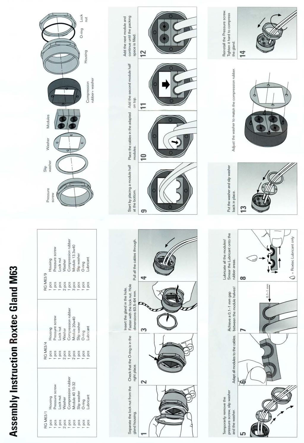
32 Automated Compounders GERMFREE works with all compounding equipment manufacturers to ensure that the equipment fits and is located properly. There are options available to install sealed cable pass trough s to allow monitors and printers to sit outside of the work area (as they should be). If you are installing automated compounding equipment please contact GERMFREE for your options. The next page gives instructions on how to use the sealed cable pass through if your unit is so equipped. You will find the vial of lubricant that is mentioned in the instructions in your cleaning kit. Use caution when setting the pass through up as it is mounted in the plastic side panel. Replacement cable modules are available if your needs change in the future, contact GERMFREE for more details. 32
33 33
34 Gloves We recommend a glove with a longer cuff length for use with the LFGI. The sleeve and bracelet system will accommodate almost any commercially available glove but some suggestions (this does not constitute product endorsement by GERMFREE) are as follows: SafeSkin by Kimberly-Clark offers Powder-Free Purple Nitrile Exam gloves in a 12 inch cuff. Chemo Plus, Chemo Bloc T, Chemo Bloc, Chemo Plus Neoprene, Chemo Bloc Nitrile and Chemo Bloc Nitrile Plus by Kendall offer a 12 inch cuff. Microflex offers many cleanroom grade gloves at a 12 inch cuff length, some sterile some non. Alarm When the low pressure alarm sounds, corrective action must be performed or the unit will require shut down to stop the alarm. Alarms are tested at the factory before shipping. Dramatic drops in pressure indicating possible containment failure are alarmed. Alarms will sound when operating work area pressures are between 0.05 and inches water column (w.c.). Normal work area pressures are 0.1 (+0.025) inches w.c. in either positive or negative overall pressures. Troubleshooting for Alarm Sounding Cause Corrective Action Glove Rip/Tear/Removal Replace Glove Sleeve Rip/Tear/Removal Replace Sleeve Inner Airlock Door open Close Inner Airlock Door View Panel not Sealed Ensure latches are fastened on view panel Pressure Hose Disconnected Reconnect small tube between control panel and work area After corrective action is taken, allow 30 seconds for alarm to reset. Observe the digital read-out to ensure that the magnitude of the number is increasing. If number does not increase and alarm continues to sound call your certifier or GERMFREE at for further troubleshooting. 34


35 Procedure for Changing Gloves During Maintenance Your standard two-part glove consists of: 1 Glove Sleeve 1 Disposable Glove 1 Glove Over Sleeve (GOS), a 3 diameter ring with three grooves on the outside 2 Glove O-rings, rubber rings that can stretch to fit around the GOS 2 Sleeve O-rings, rubber ring that can stretch to fit around the 10 gloveport 1) Pull the Glove and Sleeve out of the work area so that the sleeve is inside out and pull the existing glove and securing O-rings off. Glove Over Sleeve 2) Fold the sleeve back over the GOS so that the end of the sleeve is even with the end of the GOS. 35
.")

36 3) Stretch the Glove O-ring over the sleeve and secure in the last groove of the GOS (the one farthest away from your person). Glove O-Ring 4) Stretch the new glove cuff with both hands before trying to stretch it over the GOS will sometimes make the task easier as well as identify weaknesses in the glove before you get it into the work environment. Place the glove through the opening with the thumb pointing upward. Then stretch the glove over the GOS ring. 36

 Push the entire glove and")
37 5) Take the second Glove O-ring and slide it over the glove, securing it in the GOS groove closest to you. Glove O-Ring 6) Push the entire glove and sleeve back into the work area. 37
 Pull glove and sleeve inside-out of the work area. 2) Remove the glove O-ring. 3) Roll the existing glove s cuff down to the first groove in the GOS (the one closest to your body).")
38 Modification of glove change procedure- Changing the glove while in operation to maintain containment is possible and can become easy with practice. 1) Pull glove and sleeve inside-out of the work area. 2) Remove the glove O-ring. 3) Roll the existing glove s cuff down to the first groove in the GOS (the one closest to your body). 4) Take a new glove and stuff it inside of the existing glove leaving the cuff out and ensuring the thumb is pointed up. 5) Stretch the new glove s cuff over the old one up to the middle groove of the GOS. 6) Secure the new glove with the glove O-ring at the middle groove of the GOS. 7) Push the glove and sleeve back into the work area. 8) Reach into the work area through another glove and grab the new glove assembly. At this point the glove exposed to the work area is the old glove with the new glove trapped behind it. 9) With two fingers, carefully work the old glove off of the GOS from inside the work area. It will begin to come free in one spot. Work the free spot around the perimeter of the GOS removing the old glove. 10) Dispose of the old glove through the waste tubes and push a hand into the new glove. Sleeve Changes As seen in this picture there are two grooves on the LFGI gloveport. The sleeve can be placed at either position and secured with the Sleeve O-ring. To change a sleeve during maintenance, simply remove the securing O-ring and pull the sleeve out of the work area and off of the gloveport. Typically, new sleeves do not come with GOS or glove O-rings so save them from the existing sleeve. To order extras contact GERMFREE at To replace while maintaining containment of the work area first remove the sleeve O-ring and move the sleeve to the outermost groove. Next push the new sleeve inside of the old and pull over the gloveport down to the innermost groove. Replace 38
39 the sleeve O-ring over the new sleeve to secure it. Reach inside of the glovebox with the other glove and pull the old sleeve off and into the work area. Dispose of Sleeve through the airlock. Glove and Sleeve Inspections A visual inspection of all glove and sleeve surfaces is recommended at the beginning and end of each day. Any tears or punctures would require a replacement. If the unit is operating and is under pressure the operator can run a hand on all surfaces to feel for any air moving into or out of the work area through imperfections in the surfaces. Soap solution can also be used. If the LFGI has pressure the soap will bubble at any cut, tear or puncture. 39
40 Cleaning the LFGI- Heavy Duty (Rigorous) Outside the LFGI The outside of the LFGI can be cleaned at any time while the unit is closed and the procedure does not require PPE additional to that normally used when operating the LFGI. The stainless steel should be cleaned using a 70% alcohol solution or a solution specifically designated for the cleaning of stainless steel. The acrylic front and side panels should be cleaned with a soft cloth and a mild detergent, or a solution specifically designated for the cleaning of acrylic surfaces. It is important to never use abrasive cleaners or organic solvents on the acrylic components. Additionally, the acrylic should not be cleaned with any solution stronger than 50% ethyl or 70% isopropyl alcohol. Do not use glass cleaner with ammonia. Work from top to bottom. Do not remove or spray the prefilter at the top of the unit. When cleaning the Airlock HEPA filter housings do not directly spray, instead spray the cleaning agent into the cleaning cloth and wipe the outside surface off. Raise the stand at least 3 inches from bottom position to wipe down the caster cross supports. NEVER spray cleaner of any type directly at the control panel located above the airlock. Always spray onto a clean wipe and then wipe the surface, switches and knobs. Inside the Airlock 1. Open the outer airlock door. Spray a clean wipe with disinfectant cleaner and wipe the top HEPA filter protector from front to back moving left to right with overlapping strokes. 2. Spray the wipe with cleaner and wipe the back HEPA filter protector from top to bottom, moving left to right with overlapping strokes. 3. Spray the cleaner on the inside of the outer airlock door and remaining side and wipe from top to bottom moving left to right with overlapping strokes. 4. Open the airlock door into the work area and slide the tray out into the work area. Spray the floor of the airlock with disinfectant cleaner and wipe down. 5. Spray the tray with cleaner and wipe from left to right, and front to back with overlapping strokes. Slide the tray back into the airlock. 6. Spray the inside of the inner airlock door and wipe from top to bottom moving left to right with overlapping strokes. Close and latch the inner airlock door. 40
41 7. Repeat steps 1-6 using sterile water to rinse any disinfectant away. 8. Repeat steps 1-6 using 70% IPA to sterilize the surfaces and run a purge cycle. 41
42 Inside the LFGI A disinfectant cleaner should be used, followed by 70% alcohol. This cleaning method, when properly performed, prevents dripping of dirty solution onto cleaned surfaces and does not carry contaminants from surfaces near the open front of the work area to the rear. It is recommended to clean the airlock prior to the work area. 1. If a Positive Pressure LFGI, open the front access window. If under Negative Pressure see Note on Page Spray disinfectant cleaner on a lint-free cleaning wipe. Wipe the filter diffuser in the top of the work area wiping from side to side, overlapping strokes. Work outward from back to front. Do not spray cleaners directly at the Supply HEPA filter- always spray the cleaner onto the cleaning wipe then clean the filter protector surface. 3. Spray the back wall of the work area. Wipe the wall beginning at the top and wipe top to bottom using overlapping strokes working downward toward the work surface and wipe the rear air return grill. Work sideways from left to right. 4. Spray the sides of the work area. Using overlapping strokes, wipe top to bottom working downward toward the work surface. Be sure to clean the entire airlock door surface that is exposed to the inside of the work area, including the handle. 5. Slide the left tray over the right tray; spray the interior bottom surface of the isolator. Clean by wiping from the back to the front using overlapping strokes. Be sure to clean the sides and back under the sliding work tray and air return grill. Do not spray cleaners directly at the Exhaust HEPA filter- always spray the cleaner onto the cleaning wipe then clean the filter protector surface. 6. Slide both work trays to the left and repeat procedure #5 on the right side. Sliding work trays are removable for cleaning if preferred (simply lift them out). 7. Spray the sliding work tray and wipe using a side to side motion overlapping strokes working from back to front, and clean all inside and outside edges. 8. Slide the clean tray to the side and repeat the procedure on the other tray. 9. Remove glove sleeves and spray the inside of the open front access window. Using overlapping strokes, clean from top to bottom. 10. Spray a clean wipe with disinfectant cleaner and use it to clean glove ports. 11. Spray a clean wipe with disinfectant cleaner and use it to clean IV hanging bar and hooks. 42
43 12. Spray a clean wipe with disinfectant cleaner and wipe the front air return grill. 13. Close the front window. Clean the glove sleeves and gloves and replace on the front window. 14. Open the front window and repeat steps 1-13, without removing the sleeves and gloves, with sterile water to rinse away any disinfectant. 15. Turn on the LFGI and close the front access window. 16. Spray 70% IPA directly on all surfaces of the rest of the work area, under sliding work trays, the inside of the front access window, gloves and sleeves. 17. Allow the LFGI to run for 10 minutes before use. If the LFGI is under negative pressure all cleaning steps must be performed as described above with the viewing panel closed and through attached sleeves/gloves. GERMFREE can provide an isolator cleaning tool to assist you in this function, contact us at for more information. Cleaning the LFGI between preparations- Light Sanitizing the LFGI work area between preparations is recommended to reduce the chances of cross contamination. 70% Isopropyl Alcohol is the most recommended agent for this task. 1. Open only the outer door of the airlock. Spray a clean wipe with alcohol and wipe the top and back HEPA filter covers. 2. Spray the remaining surfaces, including the tray with alcohol and wipe with overlapping strokes. 3. Leave the spray bottle in the airlock and close the outer airlock door. Run a purge cycle. 4. Open the inner airlock door and remove the spray bottle. 5. Spray all vertical surfaces in the work area with alcohol and wipe from top to bottom with clean wipes, overlapping strokes moving left to right. 6. Spray the air grills and work surface with alcohol and wipe from left to right with overlapping strokes moving back to front. 7. Spray the sleeves and gloves and rub together, then wipe off. 8. Spray the same surfaces lightly and allow to air dry. 43
44 If all materials are wiped down prior to placement in the airlock, it should remain clean for a number of preparations in a row. 44
45 Cleaning Agents Class Recommended Use Examples Phenolic Bactericide, Fungicide, Hil-Phene, LpH, Compounds Tuberculocide, Viricide Metar, Vesphene Brand 70% Isopropyl Alcohol Solution Chlorine Compounds Quaternary Ammonium Compounds (QUATS) Cleaning certain instruments, cleaning skin Spills of human bodily fluids, bactericide, fungicide, sporicide at >1000ppm Sodium Hypochlorite Ordinary housekeeping of floors, furniture, walls, bactericide, fungicide, viricide (not as effective as phenols) 2% (W/W) Sodium Cleans and inactivates anticancer drugs on Hypochlorite 1% (W/W) 0.9% Sodium chemotherapy work surfaces Thiosulfate Bleach Solutions (Sodium Hypochlorite), Quatsyl Coverage 258, End-Bac, Hi Tor Name Brand Products Decon-Cycle by Veltek Lysol L-Stat Ultar Phene Medaphene Amphyl TexShield by Texwipe, Decon-Ahol By Veltek Clorox, Cyosan, Purex Decon-QUAT 100 By Veltek Lysol -IC Alpha-Lemon QUAT by Alphasource Surface Safe This list is by no means comprehensive nor does it constitute endorsement by GERMFREE. Read the labels on the products you are currently using to categorize them then rotate cleaning agents to avoid developing any resistant strains. Contact your current disinfectant supplier or search the internet for purchasing information. 45
46 Cleaning Terms Clean Free from disease or infectious agents <a pullorum-clean flock> <keep installations clean of TB infection> Deactivate 1 : to make inactive or ineffective 2 : to deprive of chemical activity Decontamination A process that reduces contaminating substances to a defined acceptance level. To make safe by eliminating poisonous or otherwise harmful substances, such as noxious chemicals or radioactive material. To rid of contamination (as radioactive material) Disinfect To destroy pathogenic microorganisms in or on any substance or to inhibit their growth and vital activity. To cleanse something so as to destroy or prevent the growth of disease-carrying microorganisms. To free from infection especially by destroying harmful microorganisms Sanitization That part of decontamination that reduces viable microorganisms to a defined acceptance level, normally achieved by using a chemical agent or heat. To make sanitary (as by cleaning or sterilizing) <if the apparatus is not properly sanitized, pathogens may be disseminated to subsequent patients Journal of the American Medical Association> Sterilize To make free from live bacteria or other microorganisms. References provided by: The American Heritage Stedman s Medical Dictionary Copyright 2002, 2001, 1995 by Houghton Mifflin Company. Merriam-Webster Medical Dictionary, 2002 Merriam-Webster, Inc. 46
47 The American Heritage Dictionary of the English Language, Fourth Edition copyright 200 by Houghton Mifflin Company. 47
48 LFGI- USP Specification Sheets UNIT SPECIFICATIONS SHEET LFGI-3USP LAMINAR FLOW GLOVEBOX / ISOLATOR SECTION I. PERFORMANCE DATA The Laminar Flow Glovebox/Isolator provides the ultimate in both product and operator protection. The LFGI functions as a Glovebox while operating under negative pressure to meet NIOSH recommendations and as an Isolator under positive pressure to meet USP <797> regulations. HEPA filtered unidirectional (laminar) air bathes the work area to protect the product from contamination and removes any particulate generated by sample manipulation. The operator is provided a complete barrier from materials being manipulated in the work area. The LFGI Series of barrier isolators meet or exceed ISO Class 5 air quality. Each LFGI, before shipping, undergoes rigorous physical testing to assure the unit meets performance requirements as validated. It is required that independent certification be performed before use. SECTION II. EQUIPMENT SPECIFICATIONS Construction- -Overall Dimensions: 54 W (39 W at base) x 32 D x 80 H -Work Area Dimensions: 34 ½ W x 24 ½ D x 29 H -Designed to fit through standard door openings and elevators. -All stainless steel construction both inside and out with a pharmaceutical grade finish. -316L Stainless steel work trays slide over one another and are removable to facilitate easy clean up under the work deck. -All viewing panels are stainless steel framed Acrylic -Front viewing panel is top hinged and self supporting for easy access to the work area for cleaning and equipment ingress. -All filter diffuser / guard panels are removable for easy cleaning. -Straight sides and back maximize work area to accommodate the many types and shapes of pharmacy equipment and compounders. -All corners in work area, antechamber and work surface are easily reached and cleaned. Antechamber- -Sealed two-door airlock (16 W x 13 ½ D x 14 ¼ H) maintains complete environmental separation between work area and ambient conditions. -HEPA filtered purge of trapped airlock air eliminates cross contamination between the work area and the room during both material ingress and egress. Waste Removal- -Trash tube is a 4 diameter tube, flanged for waste bag/container connection and provided with an easily removable seal/stopper to maintain work area containment. (Stainless trash can is available) -Sharps tube is a straight 2 ½ diameter tube to facilitate quick drop of the largest syringes and provided with an easily removable seal/stopper to maintain work area containment. 48
49 -Fully adjustable sharps container shelf accommodates most commercially available wide mouth or hinged top sharps collectors. (Examples BD Part # and ) Safety- -Lock-out handle requiring key for access to work area. -Digital pressure readout with low pressure alarm for work area. -Inward/Outward face velocity is linear feet per minute at gloveport opening, to protect operator/product during massive breach of containment. -Glove changes can be made without breaking containment. -Locking casters are standard, seismic anchors are available. Ergonomics- -Hydraulic assist height adjusting stand offers a full 10 range variance allowing operators to sit or stand comfortably for extended time periods. -Stainless steel sliding tray inside the airlock pulls into the work area eliminating reaching strains. -Two part sleeve/glove system allows the use of most types and sizes of commercially available gloves for better dexterity and tactility. -Extra large oval gloveports are placed with bottoms together to provide an athropometrically correct configuration that accommodates a wide range of body types and increases range of movement. -Gloveports have a 3 arm rest to reduce operator fatigue. -Large viewing panel is at an angle to reduce glare and operator strain. -Integrated foot rest. Configuration Options- -Overall work area pressure can be either positive or negative and can be altered in-place by a certifier. -Antechamber can be left or right handed or can be installed on both sides. -Waste and sharps removal tubes can be left or right handed or can be installed on both sides. -Three available exhaust options that can be factory set or changed by a certifier in-place. Filtration- -Full framed standard size minipleat HEPAs filter 100% of inlet and exhaust air from both the work area and the antechamber to provide a fully contained environment. -HEPA filters are full coverage and front loading for easy replacement by a certifier. -A Prefilter extends the life of the work area supply HEPA filter and can be replaced without tools. Electrical- -High capacity motor/blower systems with speed control to extend HEPA filters life. -Ten foot hospital grade power cord with molded grounded plug. -Sealed outlet in work area. -Separate lighted power ON/OFF indicator switches for blower and lighting. -High efficiency, standard sized fluorescent lights are externally mounted to minimize heat build-up. -Voltage = 115 Volt, 60 Hz (220/50-60 Hz also available). -Amperage Rating = 15, Running Amperage = 6 49
50 Exhaust- -Clean air plenum is external to the work area. -Constructed to allow for optional outside venting of exhaust air. -Constructed to allow for 3 exhaust options that can be factory set or changed by a certifier inplace -Venting is not required for operation but is optional. No Exhaust- ~100% recycling of air Total Exhaust- no recycling of air. Exhaust Connection N/A 8 OD flexible duct Exhaust CFM Exhaust Static N/A Up to 2 inches w.c. (depending upon configuration) Weight- Net Weight- 525 lbs Shipping Weight- 655 lbs SECTION III. OPTIONAL EQUIPMENT AND ACCESSORIES- (CONSULT YOUR SALESPERSON FOR PRICING) LFGI-A80 Ergonomic task chair with anti-bacterial and anti-microbial vinyl covering, various colors LFGI-A85S Stainless steel cleaning handle with pivot head. Accepts lint- free mop heads (LFGI-A85M) LFGI-A8E Electrical Height Adjustment (requires additional plug-in) LFGI-A83 Stainless steel garbage can (hangs on side to contain waste bags) LFGI-A12 Exhaust ventilation kits LFGI training DVD and validation documents are also available. 50
51 SECTION IV. UNIT DIAGRAM Made in the USA and available for purchase on the GSA 51
52 UNIT SPECIFICATIONS SHEET LFGI-4USP LAMINAR FLOW GLOVEBOX / ISOLATOR SECTION I. PERFORMANCE DATA The Laminar Flow Glovebox/Isolator provides the ultimate in both product and operator protection. The LFGI functions as a Glovebox while operating under negative pressure to meet NIOSH recommendations and as an Isolator under positive pressure to meet USP <797> regulations. HEPA filtered unidirectional (laminar) air bathes the work area to protect the product from contamination and removes any particulate generated by sample manipulation. The operator is provided a complete barrier from materials being manipulated in the work area. The LFGI Series of barrier isolators meet or exceed ISO Class 5 air quality. Each LFGI, before shipping, undergoes rigorous physical testing to assure the unit meets performance requirements as validated. It is required that independent certification be performed before use. SECTION II. EQUIPMENT SPECIFICATIONS Construction- -Overall Dimensions: 66 W (50 W at base) x 32 D x 80 H -Work Area Dimensions: 46 ½ W x 24 ½ D x 29 H -Designed to fit through standard door openings and elevators. -All stainless steel construction both inside and out with a pharmaceutical grade finish. -316L Stainless steel work trays slide over one another and are removable to facilitate easy clean up under the work deck. -All viewing panels are stainless steel framed Acrylic -Front viewing panel is top hinged and self supporting for easy access to the work area for cleaning and equipment ingress. -All filter diffuser / guard panels are removable for easy cleaning. -Straight sides and back maximize work area to accommodate the many types and shapes of pharmacy equipment and compounders. -All corners in work area, antechamber and work surface are easily reached and cleaned. Antechamber- -Sealed two-door airlock (16 W x 13 ½ D x 14 ¼ H) maintains complete environmental separation between work area and ambient conditions. -HEPA filtered purge of trapped airlock air eliminates cross contamination between the work area and the room during both material ingress and egress. Waste Removal- -Trash tube is a 4 diameter tube, flanged for waste bag/container connection and provided with an easily removable seal/stopper to maintain work area containment. (Stainless trash can is available) -Sharps tube is a straight 2 ½ diameter tube to facilitate quick drop of the largest syringes and provided with an easily removable seal/stopper to maintain work area containment. -Fully adjustable sharps container shelf accommodates most commercially available wide mouth or hinged top sharps collectors. (Examples BD Part # and ) Safety- 52
53 -Lock-out handle requiring key for access to work area. -Digital pressure readout with low pressure alarm for work area. -Inward/Outward face velocity is linear feet per minute at gloveport opening, to protect operator/product during massive breach of containment. -Glove changes can be made without breaking containment. -Locking casters are standard, seismic anchors are available. Ergonomics- -Hydraulic assist height adjusting stand offers a full 10 range variance allowing operators to sit or stand comfortably for extended time periods. -Stainless steel sliding tray inside the airlock pulls into the work area eliminating reaching strains. -Two part sleeve/glove system allows the use of most types and sizes of commercially available gloves for better dexterity and tactility. -Extra large oval gloveports are placed with bottoms together to provide an athropometrically correct configuration that accommodates a wide range of body types and increases range of movement. -Gloveports have a 3 arm rest to reduce operator fatigue. -Large viewing panel is at an angle to reduce glare and operator strain. -Integrated foot rest. Configuration Options- -Overall work area pressure can be either positive or negative and can be altered in-place by a certifier. -Antechamber can be left or right handed or can be installed on both sides. -Waste and sharps removal tubes can be left or right handed or can be installed on both sides. -Three available exhaust options that can be factory set or changed by a certifier in-place. Filtration- -Full framed standard size minipleat HEPAs filter 100% of inlet and exhaust air from both the work area and the antechamber to provide a fully contained environment. -HEPA filters are full coverage and front loading for easy replacement by a certifier. -A Prefilter extends the life of the work area supply HEPA filter and can be replaced without tools. Electrical- -High capacity motor/blower systems with speed control to extend HEPA filters life. -Ten foot hospital grade power cord with molded grounded plug. -Sealed outlet in work area. -Separate lighted power ON/OFF indicator switches for blower and lighting. -High efficiency, standard sized fluorescent lights are externally mounted to minimize heat build-up. -Voltage = 115 Volt, 60 Hz (220/50-60 Hz also available). -Amperage Rating = 15, Running Amperage = 6 Exhaust- -Clean air plenum is external to the work area. -Constructed to allow for optional outside venting of exhaust air. 53
54 -Constructed to allow for 3 exhaust options that can be factory set or changed by a certifier inplace -Venting is not required for operation but is optional. No Exhaust- ~100% recycling of air Total Exhaust- no recycling of air. Exhaust Connection N/A 8 OD flexible duct Exhaust CFM Exhaust Static N/A Up to 2 inches w.c. (depending upon configuration) Weight- Net Weight- 625 lbs Shipping Weight- 755 lbs SECTION III. OPTIONAL EQUIPMENT AND ACCESSORIES- (CONSULT YOUR SALESPERSON FOR PRICING) LFGI-A80 Ergonomic task chair with anti-bacterial and anti-microbial vinyl covering, various colors LFGI-A85S Stainless steel cleaning handle with pivot head. Accepts lint- free mop heads (LFGI-A85M) LFGI-A8E Electrical Height Adjustment (requires additional plug-in) LFGI-A83 Stainless steel garbage can (hangs on side to contain waste bags) LFGI-A12 Exhaust ventilation kits LFGI training DVD and validation documents are also available. SECTION IV. UNIT DIAGRAM 54
55 55
56 UNIT SPECIFICATIONS SHEET LFGI-6USP LAMINAR FLOW GLOVEBOX / ISOLATOR SECTION I. PERFORMANCE DATA The Laminar Flow Glovebox/Isolator provides the ultimate in both product and operator protection. The LFGI functions as a Glovebox while operating under negative pressure to meet NIOSH recommendations and as an Isolator under positive pressure to meet USP <797> regulations. HEPA filtered unidirectional (laminar) air bathes the work area to protect the product from contamination and removes any particulate generated by sample manipulation. The operator is provided a complete barrier from materials being manipulated in the work area. The LFGI Series of barrier isolators meet or exceed ISO Class 5 air quality. Each LFGI, before shipping, undergoes rigorous physical testing to assure the unit meets performance requirements as validated. It is required that independent certification be performed before use. SECTION II. EQUIPMENT SPECIFICATIONS Construction- -Overall Dimensions: 90 W (74 W at base) x 32 D x 80 H -Work Area Dimensions: 70 ½ W x 24 ½ D x 29 H -Designed to fit through standard door openings and elevators. -All stainless steel construction both inside and out with a pharmaceutical grade finish. -316L Stainless steel work trays slide over one another and are removable to facilitate easy clean up under the work deck. -All viewing panels are stainless steel framed Acrylic -Front viewing panel is top hinged and self supporting for easy access to the work area for cleaning and equipment ingress. -All filter diffuser / guard panels are removable for easy cleaning. -Straight sides and back maximize work area to accommodate the many types and shapes of pharmacy equipment and compounders. -All corners in work area, antechamber and work surface are easily reached and cleaned. Antechamber- -Sealed two-door airlock (16 W x 13 ½ D x 14 ¼ H) maintains complete environmental separation between work area and ambient conditions. -HEPA filtered purge of trapped airlock air eliminates cross contamination between the work area and the room during both material ingress and egress. Waste Removal- -Trash tube is a 4 diameter tube, flanged for waste bag/container connection and provided with an easily removable seal/stopper to maintain work area containment. (Stainless trash can is available) -Sharps tube is a straight 2 ½ diameter tube to facilitate quick drop of the largest syringes and provided with an easily removable seal/stopper to maintain work area containment. -Fully adjustable sharps container shelf accommodates most commercially available wide mouth or hinged top sharps collectors. (Examples BD Part # and ) Safety- 56
57 -Lock-out handle requiring key for access to work area. -Digital pressure readout with low pressure alarm for work area. -Inward/Outward face velocity is linear feet per minute at gloveport opening, to protect operator/product during massive breach of containment. -Glove changes can be made without breaking containment. -Locking casters are standard, seismic anchors are available. Ergonomics- -Hydraulic assist height adjusting stand offers a full 10 range variance allowing operators to sit or stand comfortably for extended time periods. -Stainless steel sliding tray inside the airlock pulls into the work area eliminating reaching strains. -Two part sleeve/glove system allows the use of most types and sizes of commercially available gloves for better dexterity and tactility. -Extra large oval gloveports are placed with bottoms together to provide an athropometrically correct configuration that accommodates a wide range of body types and increases range of movement. -Gloveports have a 3 arm rest to reduce operator fatigue. -Large viewing panel is at an angle to reduce glare and operator strain. -Integrated foot rest. Configuration Options- -Overall work area pressure can be either positive or negative and can be altered in-place by a certifier. -Antechamber can be left or right handed or can be installed on both sides. -Waste and sharps removal tubes can be left or right handed or can be installed on both sides. -Three available exhaust options that can be factory set or changed by a certifier in-place. Filtration- -Full framed standard size minipleat HEPAs filter 100% of inlet and exhaust air from both the work area and the antechamber to provide a fully contained environment. -HEPA filters are full coverage and front loading for easy replacement by a certifier. -A Prefilter extends the life of the work area supply HEPA filter and can be replaced without tools. Electrical- -High capacity motor/blower systems with speed control to extend HEPA filters life. -Ten foot hospital grade power cord with molded grounded plug. -Sealed outlet in work area. -Separate lighted power ON/OFF indicator switches for blower and lighting. -High efficiency, standard sized fluorescent lights are externally mounted to minimize heat build-up. -Voltage = 115 Volt, 60 Hz (220/50-60 Hz also available). -Amperage Rating = 15, Running Amperage = 7 Exhaust- -Clean air plenum is external to the work area. -Constructed to allow for optional outside venting of exhaust air. 57
58 -Constructed to allow for 3 exhaust options that can be factory set or changed by a certifier inplace -Venting is not required for operation but is optional. No Exhaust- ~100% recycling of air Total Exhaust- no recycling of air. Exhaust Connection N/A 8 OD flexible duct Exhaust CFM Exhaust Static N/A Up to 2 inches w.c. (depending upon configuration) Weight- Net Weight- 825 lbs Shipping Weight- 955 lbs SECTION III. OPTIONAL EQUIPMENT AND ACCESSORIES- (CONSULT YOUR SALESPERSON FOR PRICING) LFGI-A80 Ergonomic task chair with anti-bacterial and anti-microbial vinyl covering, various colors LFGI-A85S Stainless steel cleaning handle with pivot head. Accepts lint- free mop heads (LFGI-A85M) LFGI-A8E Electrical Height Adjustment (requires additional plug-in) LFGI-A83 Stainless steel garbage can (hangs on side to contain waste bags) LFGI-A12 Exhaust ventilation kits LFGI training DVD and validation documents are also available. SECTION IV. UNIT DIAGRAM 58
59 59

60 Certification of GERMFREE Laminar Flow Glovebox / Isolator Models: LFGI 3 USP LFGI 4 USP LFGI 6 USP Product Overview The new LFGI USP Series Laminar Flow Barrier Isolator was introduced in December 2004 and replaces the LFGI ss Rx Series. Both the LFGI and the LFGI USP series provide the operator with and environment suitable to handle both sterile preparations and potentially hazardous pharmacy drugs. The LFGI USP incorporates a more service friendly platform. The LFGI allows for all service and maintenance functions to be performed from the front of the unit (side access makes the job even easier). The LFGI USP has two Main HEPA filters, which require an integrity test and two airlock HEPA filters that are verified, in-place, with a particle counter. Additionally, supply velocities are measured and overall work area differential pressure is confirmed as part of the certification process. 60
61 Basic Operation Supply air is brought into the unit through the top prefilters and directed through the Supply HEPA filter by a series of backwards-inclined motorized impellers. This unidirectional air moves downward to the work deck then splits to the front and back air grills. Then moves under the work tray and through the exhaust HEPA filter. Next the air is forced by a second set of backwards-inclined motorized impellers up an external air recycle plenum. At the top, air being recycled is split between a 4 duct collar and recycling tip, which directs the recycled air under the prefilters and the cycle continues. Optional Exhaust tips allow for 100% exhaust of air after it passes through the Exhaust HEPA filter, this connection is via an 8 exhaust connection. Airflow Set Up To set airflow if work-area is over or under pressure as indicated by digital pressure gauge, unplug the cord going to the exhaust blower, located on the lower rear side of the LFGI and adjust supply speed control, located on the rear of the control panel. For positive pressure operation set supply HEPA filter pressure gauge to 0.50 H 2 O, for negative pressure set gauge to0.35 H 2 O for negative pressure unit. Next reconnect exhaust blowers and adjust exhaust speed control, located on the rear of the control panel, to set digital pressure gauge to the proper work-area pressure as indicated above. If further adjustments to the velocity are required, a clockwise adjustment of either speed control will always increase air velocity while each one will have an opposite effect on the work-area pressure. A counterclockwise adjustment (increase motor speed) of the exhaust blowers will lower overall unit pressure while increasing velocity and a clockwise adjustment (decrease motor speed) will lower velocity while increasing work-area pressure. For the supply blower a counterclockwise adjustment (increase motor speed) of the exhaust blowers will increase overall unit pressure while increasing velocity and a clockwise adjustment (decrease motor speed) will lower velocity while decreasing work-area pressure. Isolator Pressure Work-area can be positive or negative pressure depending on the customer s desired bias to either clean environment or containment. In either mode the unit provides unidirectional airflow and an ISO class 5 or better air quality. Pressurization should be set to positive (+) 0.09 to or negative (-) 0.09 to 0.125, inches of water on the digital pressure gauge marked work-area pressure. This overall pressure will provide greater than 100 fpm into or out of the LFGI USP in the event of a complete glove and sleeve failure, approximately 70 cfm. Supply Velocity Average Velocity Range: fpm average, all points +/- 25%. Where: 12 below Diffuser 61

62 Grid: Velocity Profile Test Grid 6" from back and sides, 6 3/4" from front LFGI 3 & 4, 5 5/8" apart left to right, 6" apart front to back LFGI 6, 6" apart left to right, 6" apart front to back Note: Above grid measurements made on work tray correspond to proper location at 12 below diffuser. Particle Counts The LFGI USP should maintain ISO Class 5 conditions in the work environment regardless of pressurization. To verify, divide the work tray into 1 square foot areas and sample the center of each zone for a minimum of 1 minute per zone. Filter Integrity The unit has two main HEPA filters, one above the work zone (supply) and one below (exhaust), see figure 1. The Supply HEPA filter should be scanned with a Photometer while challenged with DOP or equivalent. The aerosol challenge can be introduced to the upstream side of the HEPA filter through the supply blower inlet. An upstream challenge can be read through the port opposite the LFGI control panel by removing the hex head plug. If access to the side of the unit is not possible, the upstream challenge can be read through the port inside the control panel connected to the supply HEPA filter pressure gauge. For the exhaust HEPA filter the challenge is introduced into the work area and a mass flow reading should be measured in the air recycle plenum on the back top of the unit. All HEPA filters are 99.99%. Fig.1 Supply filter access (left) and Exhaust filter access (right) 62
")
63 Fig 2 Air recycle plenum (connection tip removed) 63
64 Back of the Control Panel 1. Supply Blower Control *Certifiers Only 2. Exhaust Blower Control *Certifiers Only 3. Unit Power Cord 4. Supply Blower Power Cord 5. Light Housing Power Cord 6. Exhaust Blower Power Cord 7. Work Area Outlet Power Cord 8. Airlock Supply HEPA Filter Cover Replacement Filter Sizes & Part Numbers LFGI-PF3 LFGI-3USP Prefilter (18x37x1) 12/PKG PKG LFGI-HF3S-N LFGI-3USP Supply HEPA (24x36x3) EA LFGI-HF3E-N LFGI-3USP Exhaust HEPA (12x24x6) EA LFGI-PF4 LFGI-4USP Prefilter (18x45.5x1) 12/PKG PKG LFGI-HF4S-N LFGI-4USP Supply HEPA (24x48x3) EA LFGI-HF4E-N LFGI-4USP Exhaust HEPA (12x36x6) EA LFGI-PF6 LFGI-6USP Prefilter (18x69.5x1) 12/PKG PKG LFGI-HF6S-N LFGI-6USP Supply HEPA (24x72x3) EA LFGI-HF6E-N LFGI-6USP Exhaust HEPA (12x60x6) EA LFGI-HFA-N LFGI-USP Airlock HEPA (12x12x3) EA 64
65 Pages to follow are the Operations Manual for the Sensocon Differential Pressure Gauge. We strongly recommend that you consult Germfree Customer Support before any adjustments are made. Germfree has a general access code, This would unlock the settings if asked. Generally this code is entered at the factory and would remain unlocked. 65

 248-2800 Fax: (863) 248-2798")
66 Bulletin Installation and Operation Manual Series A3 and A4 Differential Pressure Controller Sensocon, Inc. Phone: (863) Fax: (863)
67 Installation and Operation Manual Series A3 & A4 1. Introduction 1.1. Model Number Configuration 1.2. Specifications 1.3. Dimensional Drawings 2. Installation 2.1. Mounting 2.2. Pressure Connections 2.3. Electrical Connections 3. Operation 3.1. Display 3.2. Key Function 4. Programming 4.1. Menu Structure 4.2. Security Level 4.3. Main Menu 4.4. Set-Up Menu 4.5. Secure Menu 5. Other Features 5.1. Moving Program Variables 5.2. Opti-Link 5.3. Limited Warranty Contents
68 Installation and Operation Manual Series A3 & A4 1. INTRODUCTION The Sensocon A3 and A4 series of differential pressure controllers provide control of low differential pressure applications for air and other compatible non combustible gasses. These instruments have a large LED display for pressure indication, a LCD or OLED display for programming and additional LED s to indicate % of output, setpoints and alarm status. The instruments are fully programmable from the key pad face or by utilizing the Opti-Link communication port for no touch programming. Options for the instruments include a 4-20 ma output, and improved accuracies. There is also a low cost weatherproof cover available for outdoor applications. 1.1 Model Number Configuration Example A Description Model A Round Panel Mount Housing 3 LED display, process arch, LCD Display 4 LED display, process arch, OLED Control 1 Control 2 SPDT relays 0 None Transmitter ma 0 1% Accuracy % Range Specifications Maximum Pressure: Ranges 4 w.c. = 2 PSI; Ranges 5 w.c. = 10 PSI Media compatibility: Air and compatible non combustible, non corrosive gasses Accuracy*: Axxx0-xx %; Axxx1-xx % Temperature Ranges: Compensated: -10 to 140 F (-23 to 60 C) Operating: -10 to 140 F (-23 to 60 C); A3: 10 to 140 F (-12 to 60 C) Thermal Effect*: +/ % FS/ F Output Signal: 4-20 ma (option)
69 Installation and Operation Manual Series A3 & A4 Loop Resistance: 750 Ω Max (for internally sourced power); 1800 Ω Max (for externally sourced power of 36 VDC) Power Supply: Universal VAC or VDC Housing Material: Glass Filled Nylon Enclosure Rating: Designed to meet NEMA 4X face; with optional cover the entire product is weatherproof Relays: (2) SPDT VAC, VDC Electrical Connections: screw terminals Response Time: <100 ms Display: 4 Digit, red LED, ½ digits; LCD or OLED programming display Process Connection: Push on connection for 3 / 16 tubing Agency Approvals: Pending UL, C-UL, CE Patents Pending * Custom calibrations including improved accuracy and improved thermal effect are available. 1.3 Dimensional Drawings Series A3 and A4 Series A3 and A4 with optional weatherproof cover

70 Installation and Operation Manual Series A3 & A4 Optional weatherproof cover 2. INSTALLATION 2.1 Mounting Flush Mounting For new applications, cut a 4 9 / 16 hole in the panel. Insert the control with the provided gasket through the hole and secure it to the panel with the provided mounting tabs and screws. Retrofitting old technology is also easy with the Series A3 and A4. They have been designed to fit in industry standard holes ranging from 4 9 / 16 to 4 13 / 16 so simply remove the old device and insert the new control into the existing cut out.
71 Installation and Operation Manual Series A3 & A4 Surface Mounting Surface mounting the Series A3 or A4 requires the optional weather proof cover. Once the control is wired and the weather proof cover has been attached, the control can be mounted to any flat surface with the four mounting screws provided with the cover. Flush Mounting with Weather Proof cover The Series A3 and A4 can also be flush mounted with a weather proof cover. The procedure is the same as above, but utilizes two extra long mounting screws (provided with the weather proof cover) for the bottom two panel connections.
72 Installation and Operation Manual Series A3 & A4 2.2 Pressure Connections Two 3/16 pressure connections are located on the back of the unit, labeled High and Low. For best results, connect 3/16 I.D. push on tubing to the pressure connections. If the High connection has a greater absolute value than the Low connection, the front display will give a positive value. If the HI connection has a lower absolute value than the LO connection, the front display will give a negative value. 2.3 Electrical Connections NOTES: 1. Supply Voltage is universal from VAC or VDC 2. For internally sourced 4-20 ma loop, maximum loop resistance is 750 Ω; for externally sourced loop at 36 VDC, maximum loop resistance is 1800 Ω. 3. Isolation: Relays: 1000 VAC to all other inputs and outputs 4-20 ma: 5000 VAC to all other inputs and outputs.

73 Installation and Operation Manual Series A3 & A4 3. OPERATION 3.1 Display The series A3 and A4 were designed to give the user maximum feedback and flexibility. The process arch LED s are designed to mimic the indicating needle of a mechanical gauge. The process arch will light up from left to right as the pressure moves away from zero. Negative pressure will be indicated by the negative sign before the numerical indication. The 4 digit LED displays the numerical pressure reading and will show either 3 or 4 digits based on the users preference. The LCD (or OLED) display is used for programming and displaying the unit of measure and up to 4 other user selected program parameters. The LED indicators for SP1, SP2, and Alarm give indication when the parameter is in the actuated state. Negative Indication Setpoint and Alarm Indicators Process Arch LCD or OLED Programming Display LED Pressure Indication 3.2 Key Function The A3 and A4 have four buttons located on the face of the control used for programming. There is an up arrow, a down arrow, a left arrow/cancel, and a right arrow/accept button as shown below. up arrow down arrow left arrow / cancel right arrow / accept
Table of Contents. Initial Cleaning 10. Operation 11. Practice Proper Aseptic Technique 12. Rigorous Cleaning 13
 1 2 Table of Contents Receiving Instructions 1 Electrical Requirements 3 Certification 3 Safety, Operation and Additional Professional Training 4 Product Protection 4 HEPA Filtration Theory 5 Unidirectional
CTG Certification Protocol -- Version 3.0 SUMMARY
 Date of Test: Test Report Number: SUMMARY Date of Prior Certification: Certified by: Re-certification Due Date: Unit Description: Make : Model: Serial Number: Location: CERTIFIER INFORMATION Name: Client
Leaded Negative Pressure Isolator User/Service Manual. Biodex Model & Germfree LFGI Series (CACI)
") & Leaded Negative Pressure Isolator User/Service Manual Biodex Model 190-215 & 190-214. Germfree LFGI Series (CACI) GERMFREE 4 Sunshine Blvd. Ormond Beach, FL 32174 800-888-5357 Phone 386-677-1114 Fax
& Leaded Negative Pressure Isolator User/Service Manual Biodex Model 190-215 & 190-214. Germfree LFGI Series (CACI) GERMFREE 4 Sunshine Blvd. Ormond Beach, FL 32174 800-888-5357 Phone 386-677-1114 Fax
GETZ EQUIPMENT INNOVATORS PART NO.: 9G59554 MODEL: MS 36 SC-R HYDROSTATIC TEST PUMP
 GETZ EQUIPMENT INNOVATORS PART NO.: 9G59554 MODEL: MS 36 SC-R HYDROSTATIC TEST PUMP LIMITED WARRANTY Getz Equipment Innovators warrants its products, and component parts of any product manufactured by
The primary purpose of laboratory fume hoods is to keep toxic or irritating vapors out of the general laboratory working area.
 Introduction Welcome to the Biosafety Cabinets and Fume Hoods Training Course (OHS_BIO304). This training is required for anyone that will be conducting work and/or research that requires the use of a
FLANGED TWO-PIECE BALL VALVES
 INTRODUCTION This instruction manual includes installation, operation, and maintenance information for FNW flanged split-body ball valves. This manual addresses lever operated ball valves only. Please
Basic & Controlled Atmosphere Glove Boxes
 I N T R O D U C T I O N Precise Basic and Controlled Atmosphere Glove Boxes provide a leak-tight environment for work with contamination-sensitive materials. Precise Basic Glove Boxes are simple, economical
HAS2400 Hepa Air Scrubber
 HAS2400 Hepa Air Scrubber Diamonds Products 15 SW 40th Ave Great Bend, KS 67530 USA Toll Free: (866) 539-1694 Local: (620) 792-4542 Purchase Date: Serial Number: Purchased From: The DIAMOND HAS2400 HEPA
Glove Box Installation Manual
 Glove Box Installation Manual 1998 by M. Braun Company File: GB-UNI-INS.DOC! Edition 08-00 by M. Boutin! Subject to be changed without notice Glovebox Installation Your Glove box has been fully assembled,
SPECIFICATIONS TABLE Maximum Air Pressure 115 PSI Air Tank Capacity 20 Gallons
 SPECIFICATIONS TABLE Maximum Air Pressure 115 PSI Air Tank Capacity 20 Gallons Air Flow Capacity 6.2 CFM at 40 PSI 5.2 CFM at 90 PSI Motor 2.5 HP Working / 4 HP Peak 120 Volt / 60 Hz / 13 A / 1-Phase Required
Misaligned Folds Paper Feed Problems Double Feeds Won t Feed FLYER Won t Run iii
 Operator s Manual Table of Contents Operator Safety... 1 Introduction... 2 Unpacking and Setup... 3 Unpacking... 3 Setup... 4 FLYER Overview... 5 FLYER Diagram... 5 Capabilities... 5 Control Panel... 6
Installation Instructions Air Compressor Part # 2780, 2781
 Note: It is essential that the operator of this product read and understand the contents of this manual before installing and using this product. Parts Included Qty Parts Included Qty Compressor 1 Coil
92831 TEL: (714) FAX:
 FAX:") Document No. 1800-75 Respiration Test Chamber Copyright 2010 Terra Universal Inc. All rights reserved. Revised September 2010 Terra Universal, Inc. TerraUniversal.com 800 S. Raymond Ave. Fullerton, CA
Document No. 1800-75 Respiration Test Chamber Copyright 2010 Terra Universal Inc. All rights reserved. Revised September 2010 Terra Universal, Inc. TerraUniversal.com 800 S. Raymond Ave. Fullerton, CA
FLANGED TWO-PIECE BALL VALVES
 INTRODUCTION This instruction manual includes installation, operation, and maintenance information for FNW flanged split-body ball valves. This manual addresses lever operated ball valves only. Please
R2S Standard Sampling Assembly OPERATION PROCEDURE
 PURPOSE 1 of 10 To describe the procedure to monitor for viable airborne bacteria with the Remote-Slit- Sampler Assembly (R2S) from EMTEK, LLC. Principle A 100 mm agar based test plate is placed on the
Installation and Use Manual
 Installation and Use Manual EMASMB & LMASMB Surface Mount Bottle Filling Stations Model EMASMB IMPORTANT THIS IS AN INDOOR APPLICATION ONLY! ALL SERVICE TO BE PERFORMED BY AN AUTHORIZED SERVICE PERSONNEL.
SOTR Special Operations Tactical Respirator
 SOTR Special Operations Tactical Respirator OPERATOR S MANUAL FOR INDIVIDUAL RESPIRATORY PROTECTION OPS-CORE 2018 OMM G055-1000 REV. B INTRODUCTION ABOUT YOUR SOTR The Ops-Core Special Operations Tactical
FLANGED MULTI-PORT BALL VALVES
 INTRODUCTION This instruction manual includes installation, operation and maintenance information for flanged multi-port ball valves. This manual addresses lever operated ball valves only. Please refer
Aseptic Techniques. Techniques for Sterile Compounding. Pharmacy Technician Training Systems Passassured, LLC
 Aseptic Techniques Techniques for Sterile Compounding Pharmacy Technician Training Systems Passassured, LLC Aseptic Techniques, Tech for Sterile Compounding PassAssured's Pharmacy Technician Training Program
TITAN FLOW CONTROL, INC.
 PREFACE: This manual contains information concerning the installation, operation, and maintenance of Titan Flow Control (Titan FCI) Simplex Basket Strainers. To ensure efficient and safe operation of Titan
DuPont Personal Protection Instruction Manual for Universal Pressure Test Kit No
 DuPont Personal Protection Instruction Manual for Universal Pressure Test Kit No. 990810 Effective: October 2006 BE SURE TO READ AND UNDERSTAND THESE INSTRUCTIONS BEFORE ATTEMPTING TO PERFORM AN INFLATION
92831 TEL: (714) FAX:
 FAX:") Document N0. 1800-03 Copyright 2010 Terra Universal Inc. All rights reserved. Revised Sept. 2010 Terra Universal, Inc. TerraUniversal.com 800 S. Raymond Ave. Fullerton, CA 92831 TEL: (714) 578-6000 FAX:
Document N0. 1800-03 Copyright 2010 Terra Universal Inc. All rights reserved. Revised Sept. 2010 Terra Universal, Inc. TerraUniversal.com 800 S. Raymond Ave. Fullerton, CA 92831 TEL: (714) 578-6000 FAX:
Hygienic Bubble Trap Installation and Operations Manual
 Hygienic Bubble Trap Installation and Operations Manual Darren Bean / J. LaFleur 1/1/2010 Table of Contents 1.00 Warranty... 1 1.10 Exceptions... 1 1.20 Provisions... 1 2.00 Components... 1 2.10 Exploded
Model No Product Name Handpiece Only Complete System
 Ney QC 700 E 30,000 RPM IECE 30,000 R N HANDPIE IVEN HA R DRIV AIR D Owner & Operator's Manual Model No Product Name 7201326 Handpiece Only 7201325 Complete System Description Page Safety... 2 Setup...
NB/NBR NITROGEN BOOSTER FOR AVIATION SERVICE
 NB/NBR NITROGEN BOOSTER FOR AVIATION SERVICE INSTALLATION, OPERATION & MAINTENANCE MANUAL INTERFACE DEVICES, INC. 230 Depot Road, Milford, CT 06460 Ph: (203) 878-4648, Fx: (203) 882-0885, E-mail: info@interfacedevices.com
Presented by ARAMSCO
 Iso-Chamber Setup Instructions Presented by ARAMSCO STC Environmental Specialty Products A Division of Seattle Tarp Company Iso-Chamber, Isolation Chamber United States Patent No. 6,969,346 Effective 11/29/2005
BS Series Basket Strainer
 BS Series Basket Strainer Operating, Installation, & Maintenance Manual Corrosion Resistant Fluid and Air Handling Systems. Dated 04-26-12 PRESSURE DROP SIMTECH strainers are engineered to offer the lowest
MANUAL BE SERIES Test Benches
 The CustomCrimp Manual BE Series Test Benches are designed with features that make proof and burst testing of hydraulic hose assemblies a quick and easy procedure. CUSTOMIZED AND SPECIAL DESIGN BENCHES
ROPV R40 E Series User Manual
 HARBIN ROPV INDUSTRY DEVELOPMENT CENTER ROPV R40 E Series User Manual For Use with the Following ROPV Pressure Vessel Models: R40 300E R40 450E Headquarters Tel:(+86)451-82267301 Fax:(+86)451-82267303
Instruction Manual LIMITED 1 YEAR WARRANTY. Hydraulic Punch Driver Read this material before using this product.
 Instruction Manual Hydraulic Punch Driver 902-483 LIMITED 1 YEAR WARRANTY We make every effort to assure that its products meet high quality and durability standards, and warrant to the original purchaser
Read where you love to read the pool, the tub, or the beach with the waterproof Guardian Case for Kindle!
 INSTRUCTIONS AND WARRANTIES GUARDIAN CASE FOR AMAZON KINDLE LATEST GENERATION M-EDGE E-READING. E-NHANCED. TABLE OF CONTENTS STEPS AND PROCEDURES FOR PROPER CASE FUNCTION.................. Section I STEPS
Model ASSEMBLY and OPERATING INSTRUCTIONS
 QUICK CHANGE AIR BRUSH KIT Model 93506 ASSEMBLY and OPERATING INSTRUCTIONS Due to continuing improvements, actual product may differ slightly from the product described herein. 3491 Mission Oaks Blvd.,
with O 2 Controller Instruction Manual
 14500 Coy Drive, Grass Lake, Michigan 49240 734-475-2200 E-mail: sales@coylab.com www.coylab.com Hypoxic Cabinets (In-Vivo / In-Vitro) with O 2 Controller Instruction Manual Index Page Warranty 2 Warnings
RG3100 and RG3100Ice Regulator System
 RG3100 and RG3100Ice Regulator System User Guide www.diverite.com Date of purchase: www.diverite.com RG1208-5 & RG1208-5Ice www.diverite.com First Stage Regulator Product Description The RG1208-5 and RG1208-5Ice
450P- RV AUTOMATIC PORTABLE COMPRESSOR EXTREME SERIES
 450P- RV AUTOMATIC PORTABLE COMPRESSOR EXTREME SERIES PART NO. 45053 IMPORTANT: It is essential that you and any other operator of this product read and understand the contents of this manual before installing
450P AUTOMATIC PORTABLE COMPRESSOR EXTREME SERIES
 EXTREME SERIES PART NO. 45043 IMPORTANT: It is essential that you and any other operator of this product read and understand the contents of this manual before installing and using this product. SAVE THIS
This document to be used with Hurley traditional Davits
 ~ InstructIon Manual ~ This document to be used with Hurley traditional Davits WarnIngs WarnIng - Failure to install, maintain, protect, and operate the system properly can cause malfunction resulting
AIR/OVER HYDRAULIC JACK 20 TON
 AIR/OVER HYDRAULIC JACK 0 TON 4487 ASSEMBLY AND OPERATING INSTRUCTIONS 349 Mission Oaks Blvd., Camarillo, CA 930 Visit our Web site at http://www.harborfreight.com Copyright 999 by Harbor Freight Tools.
accidents which arise due to non-observance of these instructions and the safety information herein. SPECIFICATIONS
 18 GAUGE 1-1/4 INCH BRAD NAILER Model: 7611 CALIFORNIA PROPOSITION 65 WARNING: You can create dust when you cut, sand, drill or grind materials such as wood, paint, metal, concrete, cement, or other masonry.
BIOSAFETY SELF AUDIT PRINCIPAL INVESTIGATOR/PERMIT HOLDER: CONTAINMENT LEVEL: 1 2 (Shaded) RISK GROUP: 1 2 AUDIT TO BE COMPLETED BY (DATE):
 RISK GROUP: 1 2 AUDIT TO BE COMPLETED BY (DATE):") Page 1 of 5 BIOSAFETY PROGRAM BIOSAFETY SELF AUDIT PRINCIPAL INVESTIGATOR/PERMIT HOLDER: SELF AUDIT COMPLETED BY: LABORATORY ROOM NUMBER: CONTAINMENT LEVEL: 1 2 (Shaded) RISK GROUP: 1 2 DATE OF AUDIT:
Page 1 of 5 BIOSAFETY PROGRAM BIOSAFETY SELF AUDIT PRINCIPAL INVESTIGATOR/PERMIT HOLDER: SELF AUDIT COMPLETED BY: LABORATORY ROOM NUMBER: CONTAINMENT LEVEL: 1 2 (Shaded) RISK GROUP: 1 2 DATE OF AUDIT:
UE- 90- X X X X X X O P E R AT I N G M A N UA L 0 TO 90 HYDRAULIC UPENDER
 UE- 90- X X X X X X O P E R AT I N G M A N UA L ADDRESS 2230 Brush College Road Decatur, IL 62526 Phone: 217-423-6001 Fax: 217-422-1049 E-mail: sales@alignprod.com www.alignproductionsystems.com UE-90-XXXXXX
8675/8677/8678 OWNER S MANUAL
 8675/8677/8678 OWNER S MANUAL SERIAL NUMBER: DATE OF MANUFACTURE: 8675 MAXIMUM PATIENT WEIGHT: 250 LBS. 8677/8678 MAXIMUM PATIENT WEIGHT: 375 LBS. 1316 Eisenhower Blvd Johnstown, PA 15904 (814) 266 8726
VERTICAL AIR COMPRESSORS
 VERTICAL AIR COMPRESSORS MODEL NO: VE11C150, VE15C150, VE18C150 PART NO: 2226005, 2226000, 2226015 OPERATION & MAINTENANCE INSTRUCTIONS LS0615 INTRODUCTION Thank you for purchasing this CLARKE Vertical
Sterile Visual Flow Indicator
 Sterile Visual Flow Indicator Sanitary Process Connection Installation / Operation / Maintenance Manual P.O. Box 1116 Twinsburg, OH 44087 Phone: 330/405-3040 Fax: 330/405-3070 E-mail: view@ljstar.com Web
PRODUCT SUPPORT MANUAL YACHT BEAM 6M Searchlight Remote Control System with Joystick Remote Control Panel
 PRODUCT SUPPORT MANUAL YACHT BEAM 6M Searchlight Remote Control System with Joystick Remote Control Panel The Yacht Group - 4545 Ponce de Leon Blvd. Coral Gables FL 33146 Tel. 305.667.5811 - Fax. 305.663.5551
3 Scotch-Weld Polyurethane Reactive Adhesive Applicator Replacement Part Installation Guide
 3 Scotch-Weld Polyurethane Reactive Adhesive Applicator Replacement Part Installation Guide Description: AIR SUPPLY LINE KIT Product ID/Stock No.: 62-9895-0005-3 For use with: 3M Scotch-Weld Polyurethane
INSTALLATION. and INSTRUCTION MANUAL. for QUALITY AIR BREATHING SYSTEMS. Model 50-P-Mini Portable Systems Outfitted with ABM-725 Monitor
 INSTALLATION and INSTRUCTION MANUAL for QUALITY AIR BREATHING SYSTEMS Model 50-P-Mini Portable Systems Outfitted with ABM-725 Monitor M A R T E C H S E R V I C E S C O M P A N Y P.O. Box 7079 OFFICE: (507)
KJ4000 Operating Instructions & Parts Manual NSN
 KJ4000 Operating Instructions & Parts Manual NSN 1025-01-473-7710 Mandus Group Ltd. KJ4000 Operators Manual Date: 3 Jan. 2002 TABLE OF CONTENTS General Safety Instructions...Page 1 Operator Instructions...Page
SUMMITTM 400 & 600. Natural Gas Barbecues. Step-By-Step Guide
 SUMMITTM 400 & 600 Natural Gas Barbecues Step-By-Step Guide W E B E R W E B E R W E B E R W E B E R Summit 400 NG Summit 600 NG CANADIAN GAS ASSOCIATION R A P P R O V E D WARNING: Follow all leak check
Vessel Installation and Operating Manual
 For In-ground and Aboveground Pools Vessel Installation and Operating Manual Important Safety Information Please read this manual prior to installation. Nature 2 Express is designed to sanitize in-ground
VOLLEYBALL SPIKE TRAINER. Assembly Instructions. Owner s Manual. Model # VST-400. Club Volleyball Gear
 VOLLEYBALL SPIKE TRAINER Model # VST-400 Wall-mount Volleyball Spike Trainer with 28 height adjustment range Assembly Instructions Owner s Manual Club Volleyball Gear 18434 Technology Drive, Morgan Hill,
VOLLEYBALL SPIKE TRAINER. Assembly Instructions. Owner s Manual. Model # VST-300. Club Volleyball Gear. For fixed-height Basketball Hoop Systems
 VOLLEYBALL SPIKE TRAINER Model # VST-300 For fixed-height Basketball Hoop Systems Assembly Instructions Basketball Hoop System Not Included Owner s Manual Club Volleyball Gear 18434 Technology Drive, Morgan
PC1131 Electric Air Compressor
 Senco Products Inc. 8485 Broadwell Road Cincinnati, Ohio 45244 PC1131 Electric Air Compressor Operating Instructions C US 2006, 2007 by Senco Products, Inc. Warnings for the safe use of this tool are included
Angled Sign Light with Shade
 Angled Sign Light with Shade Owner s Manual WARNING: Read carefully and understand all ASSEMBLY AND OPERATION INSTRUCTIONS before operating. Failure to follow the safety rules and other basic safety precautions
PRS(TC)4,8 USER MANUAL. Read the complete manual before installing and using the regulator.
4,8 USER MANUAL. Read the complete manual before installing and using the regulator.") PRS(TC)4,8 USER MANUAL Read the complete manual before installing and using the regulator. WARNING INCORRECT OR IMPROPER USE OF THIS PRODUCT CAN CAUSE SERIOUS PERSONAL INJURY AND PROPERTY DAMAGE. Due to
PRS(TC)4,8 USER MANUAL Read the complete manual before installing and using the regulator. WARNING INCORRECT OR IMPROPER USE OF THIS PRODUCT CAN CAUSE SERIOUS PERSONAL INJURY AND PROPERTY DAMAGE. Due to
SDS -Series 4C-D201/-D202 Supplemental Drying System User s Manual
 SDS -Series 4C-D201/-D202 Supplemental Drying System User s Manual 8 Executive Drive P.O. Box 2105 Toms River, NJ 08754 (732) 244-0010 (800) 337-3762 fax (732) 244-8140 www.permapure.com info@permapure.com
S&S. Installation Instructions: S&S Stealth Air Cleaner Kit for Harley-Davidison Models With Stock Cable Operated Delphi EFI
 Instruction 510-0388 01-11-16 Version 1 Copyright 2016 by S&S Cycle, Inc. All rights reserved. Printed in the U.S.A. S&S Cycle, Inc. 14025 Cty Hwy G PO Box 215 Viola, Wisconsin 54664 Phone: 608-627-1497
VECTA DELUXE SENSORY DISTRACTION STATION INSTRUCTION MANUAL
 VECTA DELUXE SENSORY DISTRACTION STATION INSTRUCTION MANUAL SET UP INSTRUCTIONS Read Instructions First The Vecta is a mobile cart that allows you to take the Multi-Sensory experience from room to room.
LRS(H)4 USER MANUAL. Read the complete manual before installing and using the regulator.
4 USER MANUAL. Read the complete manual before installing and using the regulator.") LRS(H)4 USER MANUAL Read the complete manual before installing and using the regulator. WARNING INCORRECT OR IMPROPER USE OF THIS PRODUCT CAN CAUSE SERIOUS PERSONAL INJURY AND PROPERTY DAMAGE. Due to the
LRS(H)4 USER MANUAL Read the complete manual before installing and using the regulator. WARNING INCORRECT OR IMPROPER USE OF THIS PRODUCT CAN CAUSE SERIOUS PERSONAL INJURY AND PROPERTY DAMAGE. Due to the
Installation and Operating Manual
 Safety Instructions Important Information Please read prior to installation ATTENTION! ELECTRICAL HAZARD FOR INGROUND POOLS AND ABOVEGROUND POOLS Installation and Operating Manual IMPORTANT Pool Owner,
1.0 PURPOSE The purpose of this procedure is to describe the use of basic aseptic technique.
 1.0 PURPOSE The purpose of this procedure is to describe the use of basic aseptic technique. 2.0 RESPONSIBILITY 2.1 It is the responsibility of each employee working in a laboratory setting to follow this
Multi-Probe Sampling System User Guide & Manual
 Multi-Probe Sampling System User Guide & Manual Rev. 06/05/12 Part #22200012 Table of Contents CHAPTER 1: SYSTEM DESCRIPTION... 2 FUNCTION AND THEORY... 3 SYSTEM COMPONENTS... 4 CHAPTER 2: SYSTEM INSTALLATION...
accidents which arise due to non-observance of these instructions and the safety information herein. SPECIFICATIONS
 18 GAUGE 2 INCH BRAD NAILER Model: 7555 CALIFORNIA PROPOSITION 65 WARNING: You can create dust when you cut, sand, drill or grind materials such as wood, paint, metal, concrete, cement, or other masonry.
6500 KNIFE GATE VALVES
 INTRODUCTION This instruction manual includes installation, operation and maintenance information for 2" through 30" stainless steel and stainless steel lined knife gate valves. This manual addresses hand-wheel
RS(H)10,15 USER MANUAL. Read the complete manual before installing and using the regulator.
10,15 USER MANUAL. Read the complete manual before installing and using the regulator.") RS(H)10,15 USER MANUAL Read the complete manual before installing and using the regulator. WARNING INCORRECT OR IMPROPER USE OF THIS PRODUCT CAN CAUSE SERIOUS PERSONAL INJURY AND PROPERTY DAMAGE. Due to
RS(H)10,15 USER MANUAL Read the complete manual before installing and using the regulator. WARNING INCORRECT OR IMPROPER USE OF THIS PRODUCT CAN CAUSE SERIOUS PERSONAL INJURY AND PROPERTY DAMAGE. Due to
J Air and Water Kit Instructions Part# 02584
 J Air and Water Kit Instructions Part# 02584 Unpacking Please open and inspect your package upon receipt. Your package was packed with great care and all the necessary packing materials to arrive to you
SAFEsystem. Safety Apparatus Filter Enhancement. Filtration Systems. Now you can safely control your filtering process
 Now you can safely control your filtering process BROCHURE C1 SAFEsystem TM Safety Apparatus Filter Enhancement Available on Individual, Duplex or Multi-Housing ASME Code filter systems. Filtration Systems
Marschalk Model # 94000
 Marschalk Model # 94000 12-volt DC Portable oil-less Air Compressor Operation Manual 27250006 REV 1 9/13/05 Table of Contents CHAPTER 1: SYSTEM DESCRIPTION... 5 FUNCTION AND THEORY... 5 SYSTEM COMPONENTS...
STAINLESS STEEL TABLES
 INSTRUCTION MANUAL STAINLESS STEEL TABLES USAGE AND MAINTENANCE Read and understand all of the instructions and safety information in this manual before operating this product. MAN-050 REV A 2018 MAC Medical,
Pressure Injection Cell Operator s Manual
 Pressure Injection Cell Operator s Manual Operator s Manual Pressure Injection Cell CONGRATULATIONS! Congratulations on your purchase of a Next Advance Pressure Injection Cell. Please read this operator
SSFU SUPER SPRAYFAST UNIVERSAL ADHESIVE APPLICATOR
 S S F U SSFU SUPER SPRAYFAST UNIVERSAL ADHESIVE APPLICATOR MACHINERY DIVISION OWNER S MANUAL UNIT INSTRUCTIONS Please follow all SSFU Safety Instructions. Contact your Duro Dyne Tech Service if you have
VOLLEYBALL SPIKE TRAINER. Assembly Instructions. Owner s Manual. Model # VST-200. Club Volleyball Gear. For height-adjustable Basketball Hoop Systems
 VOLLEYBALL SPIKE TRAINER Model # VST-200 Basketball Hoop System Not Included For height-adjustable Basketball Hoop Systems Assembly Instructions Owner s Manual Club Volleyball Gear 18434 Technology Drive,
AMP Oil Free Manual AMP 50-8-TC AMP 50-6-D AMP General User and Maintenance Instructions
 AMP Oil Free Manual AMP 50-8-TC AMP 50-6-D AMP 50-24 General User and Maintenance Instructions Silentaire Technology 8614 Veterans Memorial Dr. Houston, TX 77088 800-972-7668 Fax 832-327-0669 www.silentaire.com
KTM OM-2 SPLIT BODY FLOATING BALL VALVES INSTALLATION AND MAINTENANCE INSTRUCTIONS
 Before installation these instructions must be fully read and understood SECTION 1 - STORAGE 1.1 Preparation and preservation for storage All valves should be properly packed in order to protect the parts
Congratulations on your purchase of a JC Series Performer trike! The Performer JC Series is designed for everything from touring to commuting and
 Congratulations on your purchase of a JC Series Performer trike! The Performer JC Series is designed for everything from touring to commuting and shopping in the city. The JC Series frames are made of
R E D I C O N T R O L S
 R E D I C O N T R O L S Operation & Maintenance Manual Portable Service Purger for Low Pressure Chillers Model: PSP-LP-1B For Refrigerants R-11, R-113, R-114 & R-123 & Other Similar Refrigerants File Literature
Vertex VP Operation and Maintenance
 AIRBENCH LTD Vertex VP Operation and Maintenance This Edition: 2 October 2018 AirBench Ltd, 14 Grange Farm Road, Colchester CO2 8JW www.airbench.com +44 (0) 1206 791191 Copyright AirBench Ltd 2016 Page
Table of Contents Documentation for PIT TROLLEY A4
 Table of Contents Documentation for PIT TROLLEY A4 Declaration of conformity 1 Safety instructions and routines to check for safety 2 Description of features and technical data 3 Assembly instructions
GALISO SOAP OPTION FOR PCT-ADW-D
 GALISO SOAP OPTION FOR PCT-ADW-D Installation and Operation Instructions MANUAL NUMBER 21-11-1008 Issued March 2016 Rev B 09/26/2018 Copyright 2016 - Galiso, Incorporated 22 Ponderosa Ct., Montrose, CO
Installation and Operating Guide Document No Smart Glovebox Copyright 2017 Terra Universal Inc. All rights reserved. Revised Nov.
 Document No. 1800-79 Copyright 2017 Terra Universal Inc. All rights reserved. Revised Nov. 2017 Terra Universal, Inc. TerraUniversal.com 800 S. Raymond Ave. Fullerton, CA 92831 TEL: (714) 578-6000 FAX:
EMT EnvironmentalMonitoringTECHNOLOGIES
 1 of 11.PURPOSE To describe the procedure to monitor for viable airborne bacteria with the R2S Remote Start Sampling Assembly from EMT. Principle A 100 mm agar based test plate is placed on the turntable
Vertical Lifeline. Ladder Climb. User Instructions. 3M Occupational Health and Environmental Safety. Fall Protection Equipment
 3M Occupational Health and Environmental Safety Fall Protection Equipment Ladder Climb Vertical Lifeline User Instructions User Instructions for the 3M TM Ladder Climb Vertical Lifeline System. Important:
200 A, 15 and 25 kv class loadbreak bushing insert installation instructions
 Loadbreak Apparatus Connectors Effective October 2013 Supersedes March 2011 200 A, 15 and 25 kv class loadbreak bushing insert installation instructions S500-12-1 DISCLAIMER OF WARRANTIES AND LIMITATION
VOLLEYBALL SPIKE TRAINER. Assembly Instructions. Owner s Manual. Model # VST-100. Club Volleyball Gear WARNING
 VOLLEYBALL SPIKE TRAINER Model # VST-100 Assembly Instructions Owner s Manual WARNING To ensure safety, do not attempt to assemble this system without following all instructions carefully. Check entire
VERTICAL AIR COMPRESSORS
 VERTICAL AIR COMPRESSORS MODEL NO: VE15C150, VE18C150, VE25C150 PART NO: 2226010, 2226020, 2226025 OPERATION & MAINTENANCE INSTRUCTIONS LS0715 INTRODUCTION Thank you for purchasing this CLARKE Vertical
14500 Coy Drive, Grass Lake, Michigan Isolation Glove Box Instruction Manual
 14500 Coy Drive, Grass Lake, Michigan 49240 734-475-2200 E-mail: sales@coylab.com www.coylab.com Isolation Glove Box Instruction Manual Index Page Warranty 1 1.0 Warnings 2 2.0 General Overview 3 3.0 Care
USER MANUAL FLOW SELECTOR PM1000 SAVE THESE INSTRUCTIONS. Federal (USA) law restricts this device to sale by or on the order of a physician.
 law restricts this device to sale by or on the order of a physician.") USER MANUAL FLOW SELECTOR PM1000 SAVE THESE INSTRUCTIONS CAUTION Federal (USA) law restricts this device to sale by or on the order of a physician. RECEIVING / INSPECTION Remove the Precision Medical,
USER MANUAL FLOW SELECTOR PM1000 SAVE THESE INSTRUCTIONS CAUTION Federal (USA) law restricts this device to sale by or on the order of a physician. RECEIVING / INSPECTION Remove the Precision Medical,
AIR INLINE METAL SHEAR
 AIR INLINE METAL SHEAR ASSEMBLY and OPERATING INSTRUCTIONS 3491 Mission Oaks Blvd. / Camarillo, CA 93011 Copyright 1997 by Harbor Freight Tools. All rights reserved. No portion of this manual or any artwork
Installation and Operation Manual
 Installation and Operation Manual Installation, Operation, and Service Information Pulse Jet Filters Models FSD, VSD, FTD, VTD, FSDC, VSDC, FTP, RSD, RTD, RTP Throughout this manual statements indicating
SIX R (P ) AND SEVEN R (P ) POSITION CYLINDERS Service Information
 AND SEVEN R (P ) POSITION CYLINDERS Service Information") SIX R431006322 (P -063892-00001) AND SEVEN R431006321 (P -063981--00002) POSITION CYLINDERS Service Information The six and seven position cylinders are medium duty pneumatic positioning devices that operate
SIX R431006322 (P -063892-00001) AND SEVEN R431006321 (P -063981--00002) POSITION CYLINDERS Service Information The six and seven position cylinders are medium duty pneumatic positioning devices that operate
SSS SWEEPERS MODELS MS-31 & MS-39
 SSS SWEEPERS MODELS MS-31 & MS-39 INTRODUCTION OPERATING & MAINTENANCE INSTRUCTIONS READ THIS BOOK This operator s book has important information for the use and safe operation of this machine. Read this
Installation of Your SprayMaster System
 Installation of Your SprayMaster System 1. At the installation site, remove all equipment from the corrugated box and the polyethylene drum and replace the drum lid. Check the picture to identify each
AC1810 / AC1810-A TECHNICAL SPECIFICATIONS. Operating Pressure psi ( kgs/cm²) [AC1810] Displacement. Net Weight
![AC1810 / AC1810-A TECHNICAL SPECIFICATIONS. Operating Pressure psi ( kgs/cm²) [AC1810] Displacement. Net Weight](/thumbs/83/88369739.jpg "AC1810 / AC1810-A TECHNICAL SPECIFICATIONS. Operating Pressure psi ( kgs/cm²) [AC1810] Displacement. Net Weight") Technical Specifications Operating Instructions Maintenance Information Troubleshooting Guide Parts Diagrams AC1810 / AC1810-A THE EVOLUTION OF PERFECTION CAUTION: Before attempting to use or service this
Technical Specifications Operating Instructions Maintenance Information Troubleshooting Guide Parts Diagrams AC1810 / AC1810-A THE EVOLUTION OF PERFECTION CAUTION: Before attempting to use or service this
User Guide. Pall Laboratory Manifold. For laboratory use. Not for use in a manner other than indicated. Introduction. Regulatory References
 User Guide Pall Laboratory Manifold For laboratory use. Not for use in a manner other than indicated. Introduction Application and Intended Use The membrane filtration (MF) technique is a method of analyzing
12 Inch Barn Light. Owner s Manual
 12 Inch Barn Light Owner s Manual WARNING: Read carefully and understand all ASSEMBLY AND OPERATION INSTRUCTIONS before operating. Failure to follow the safety rules and other basic safety precautions
Interface Devices, Inc. Hydraulic Mini Mule
 Interface Devices, Inc. Hydraulic Mini Mule INSTALLATION, OPERATION & MAINTENANCE MANUAL IMPORTANT! FILE THIS MANUAL IN A SAFE PLACE FOR FUTURE SERVICE & PARTS NEEDS ALWAYS REFERENCE THE SERIAL NUMBER
C - SERIES. Height Adjustable Portable Goal Supports. Installation & Owner s Instructions C1000 C2000. Made in the USA
 C - SERIES Height Adjustable Portable Goal Supports C1000 C2000 Installation & Owner s Instructions Made in the USA This manual explains the proper installation, operation, and maintenance of your Schutt
RAM 4021 Operation Manual
 RAM 4021 Operation Manual Worldwide Manufacturer of Gas Detection Solutions TABLE OF CONTENTS RAM 4021 For your safety...3 Description...3 Set-up mode...4 Annunciator lights/alarms...4 Operation...5 Calibration...6
InstallatIon and owner s InstrUCtIons
 InstallatIon and owner s InstrUCtIons Wall Mount Series Adjustable and Fixed Height Goal Systems table of Contents Safety Instructions... 2 Goal Specifications... 3 Frame Attachment... 4 Frame Assembly
97C COMPRESSOR KIT 12V PART NO C COMPRESSOR KIT 24V PART NO C COMPRESSOR KIT PART NO
 97C COMPRESSOR KIT 12V PART NO. 00097 97C COMPRESSOR KIT 24V PART NO. 02497 98C COMPRESSOR KIT PART NO. 00098 97C 98C IMPORTANT: It is essential that you and any other operator of this product read and