Flow Through Axial and Centrifugal Compressors by Kartik Sharma Mentors Prof. Gautam Biswas Prof. Subrata Sarkar
|
|
|
- Joseph Reeves
- 6 years ago
- Views:
Transcription
1 6 th Indo-German Winter Academy 2007 IIT Guwahati, India, December 13-19, 2007 Flow Through Axial and Centrifugal Compressors by Kartik Sharma Mentors Prof. Gautam Biswas Prof. Subrata Sarkar
2 Outline of the Presentation Introduction to Dynamic Compressors Axial Compressors- Basic Working Principle Centrifugal Compressors- Basic Working Principle Flow through Axial Compressors Flow through Centrifugal Compressors Comparison of Axial and Centrifugal Compressors Summary
3 Introduction-Dynamic Compressors Density of the fluids change with temperature and pressure as they pass through the compressible flow or Turbo machines. Dynamic Machines (a type of turbo machines) use rotating vanes or impellers to impart velocity and pressure to the gas. These machines operate by developing a high gas velocity and converting this velocity into pressure in the diffusing flow passage. They do operate at relatively higher speeds to provide higher flow rate in relation to their physical size. There are mainly two types of Dynamic Compressors - 1. Centrifugal Compressors 2. Axial Compressors

4 Axial Compressors They are rotating, aerofoil based compressors in which the working fluid principally flows parallel to the axis of rotation. They produce a continuous flow of compressed air, have the benefits of high efficiencies and large mass flow capacity, particularly in relation to their cross-section.
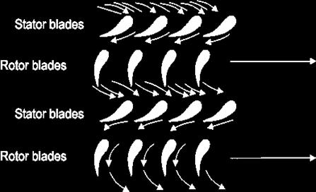
5 Basic Principles of Axial Compressors The basic components of an axial flow compressor are a rotor and stator, the former carrying the moving blades and the latter the stationary rows of blades. The stationary blades convert the kinetic energy of the fluid into pressure energy, and also redirect the flow into an angle suitable for entry to the next row of moving blades. Each stage will consist of one rotor row followed by a stator row, but it is usual to provide a row of so called Inlet guide vanes at the beginning. For a compressor, a row of rotor blades followed by a row of stator blades is called a Stage
6 Working of Axial Compressors

7 Centrifugal Compressors A centrifugal compressor is a radial flow rotodynamic fluid machine that uses mostly air as the working fluid and utilizes the mechanical energy imparted to the machine from outside to increase the total internal energy of the fluid mainly in the form of increased static pressure head.


8 Components of a Centrifugal Compressor A centrifugal compressor consists of three main parts; A Stationary Casing A Rotating Impeller which imparts high velocity to the fluid. It may be single or double sided. A Diffuser having a number of fixed diverging passages in which the air is decelerated with consequent rise in pressure.

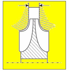
9 Schematic Views of a centrifugal compressor

10 The figure shows the sectional diagram of a single entry and single outlet centrifugal compressor.
11 Principle of Operation Air is sucked into the impeller eye and whirled outwards at high speed by the impeller disk. At any point in the flow of air through the impeller the centripetal acceleration is obtained by a pressure head so that the static pressure of the air increases from the eye to the tip of the impeller. The remainder of the static pressure rise is obtained in the diffuser, where the very high velocity of air leaving the impeller tip is reduced to almost the velocity with which the air enters the impeller eye.
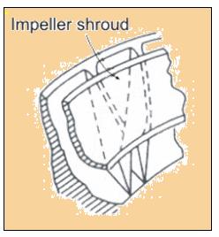
12 Usually, about half of the total pressure rise occurs in the impeller and the other half in the diffuser. Owing to the action of the vanes in carrying the air around with the impeller, there is a slightly higher static pressure on the forward side of the vane than on the trailing face. The air will thus tend to flow around the edge of the vanes in the clearing space between the impeller and the casing. This results in a loss of efficiency and the clearance must be kept as small as possible. Sometimes, a shroud attached to the blades to eliminate such a loss, but it is avoided because of increased disc friction loss and of manufacturing difficulties.
13 Parameters of Compressor Operation Normal Operating Point- It is the head-capacity point at which the usual operation is expected and at which optimum efficiency is desired Compressor Rated Point- It is determined as follows; 1. The highest speed necessary to meet any specified operating conditions. 2. The rated capacity required by compressor designs to meet all operating points. This capacity point is selected to best encompass the specified operating conditions within the scope of the expected performance curve.
14 Normal Speed- It is the speed corresponding to the requirements of the normal operating point. One hundred percent speed- It is the speed corresponding to the requirements of the compressor rated point. It may be greater than or equal to the normal speed. Maximum continuous speed- It is the upper limit of the operating speed of the compressor. For variable speed compressors, it should be 105% of the speed of the compressor rated point.
15 Operating Characteristics of a Compressor The operating range is the region between the surge point and the choke point. Surge point is the point when the flow is reversed in the compressor.
16 Choke point is the point when the flow has reached a Mach=1.0,the point where no more flow can get through the unit, a Stone Wall. When Surge occurs, the flow is reversed and all the forces acting on the compressor (specially thrust forces) can lead to the destruction of the compressor. Choke conditions cause a large drop in efficiency but don t lead to any destruction of the unit.
17 Blade Types of a Compressor There are three impeller vane types defined according to the exit blade angles; Impellers with exit blade angle equal to 90 degrees are radial vanes Impellers with exit blade angle less than 90 degrees are backwardcurved or backward swept. Vanes with exit blade angle greater than 90 degrees are known as forward swept vanes. The forward-curved blade has the highest theoretical head. Backward-curved blades are most common since they have the lowest velocity leaving the impeller so diffuser has a much smaller head to convert. They also have a larger operational margin.
18 Blade Geometry They do suffer from problems of low energy transfer and complex bending stresses.
19 Compressor Characteristics The performance of a compressor is usually specified by curves of delivery pressure and temperature against mass flow rate for various fixed values of rotational speed at given values of inlet pressure and temperature. It is better to plot such performance characteristic curves with dimensionless variables. where D = characteristic linear dimension of the machine, N = rotational, m = mass flow rate,p01 = stagnation pressure at compressor inlet, = p02 stagnation pressure at compressor outlet, = t01,stagnation temperature at compressor inlet, t02= stagnation temperature at compressor outlet, and R = characteristics gas constant
20 Contd.. By making use of Buckingham's π theorem, we obtain the nondimensional groups (π terms) as ; The third and fourth non-dimensional groups are defined as 'nondimensional mass flow' and 'non-dimensional rotational speed' respectively. The physical interpretation of these two non-dimensional groups can be ascertained as follows;
21 Contd.. Therefore, the 'non-dimensional mass flow' and 'non-dimensional rotational speed' can be regarded as flow Mach number, and rotational speed Mach number, When we are concerned with the performance of a machine of fixed size compressing a specified gas, R and D may be omitted from the groups and we can write
22 Contd.. Though the terms and are truly not dimensionless, they are referred as 'non-dimensional mass flow' and 'non-dimensional rotational speed' for practical purpose. The stagnation pressure and temperature ratios and are plotted against in the form of two families of curves, each curve of a family being drawn for fixed values of. The two families of curves represent the compressor characteristics. From these curves, it is possible to draw the curves of isentropic efficiency for fixed values of Isentropic Efficiency is defined as;

23 Performance Curve of Centrifugal Compressors Point A- Represents the centrifugal pressure head produced by the action of the impeller on the air trapped between the vanes
24 Point B- Efficiency approaches its maximum and the pressure ratio also reaches its maximum. Further increase of mass flow will result in a fall of pressure ratio For mass flows greatly in excess of that corresponding to the design mass flow, the air angles will be widely different from the vane angles and breakaway of the air will occur. The pressure ratio drops to unity at 'C', when the valve is fully open and all the power is absorbed in overcoming internal frictional resistances
25 The operating point 'A' could be obtained but a part of the curve between 'A' and 'B' could not be obtained due to Surging. For any operating point D on the part of characteristics curve having a positive slope, a decrease in mass flow will be accompanied by a fall in delivery pressure. If the pressure of the air downstream of the compressor does not fall quickly enough, the air will tend to reverse its direction and will flow back in the direction of the resulting pressure gradient. When this occurs, the pressure ratio drops rapidly causing a further drop in mass flow until the point 'A' is reached, where the mass flow is zero.
26 When the pressure downstream of the compressor has reduced sufficiently due to reduced mass flow rate, the positive flow becomes established again and the compressor picks up to repeat the cycle of events which occurs at high frequency For any operating point on the part of the characteristics having a negative slope, decrease in mass flow is accompanied by a rise in delivery pressure and the operation is stable There is an additional limitation to the operating range, between 'B' and 'C'. As the mass flow increases and the pressure decreases, the density is reduced and the radial component of velocity must increase.
27 At constant rotational speed this means an increase in resultant velocity and hence an angle of incidence at the diffuser vane leading edge. At some point say 'E', the position is reached where no further increase in mass flow can be obtained no matter how wide open the control valve is. This point represents the maximum delivery obtainable at the particular rotational speed for which the curve is drawn.

28 This indicates that at some point within the compressor sonic conditions have been reached, causing the limiting maximum mass flow rate to be set for the compressible flow. Choking is said to have taken place. Variations of pressure ratio over the complete range of mass flow for different rotational speeds
29 Analysis of an Axial Compressor An axial compressor is typically made up of many alternating rows of rotating and stationary blades called rotors and stators, respectively. Bernoulli Equation The first stationary row (which comes in front of the rotor) is typically called the inlet guide vanes or IGV. Each successive rotor-stator pair is called a compressor stage. Hence compressors with many blade rows are termed multistage compressors. Where: P T is the stagnation pressure P is the static pressure u is radial velocity v is tangential velocity w is axial velocity
30 The rotor adds swirl to the flow increasing the total energy carried in the flow by increasing the angular momentum (adding to the kinetic energy associated with the tangential or swirl velocity, ). The stator removes swirl from the flow. The stator rather converts the kinetic energy associated with swirl to internal energy (raising the static pressure of the flow). IGV also adds no energy to the flow. It is designed to add swirl in the direction of rotor motion to lower the Mach number of the flow relative to the rotor blades, and thus improve the aerodynamic performance of the rotor

31 Velocity and Pressure Profiles
32 Characteristics of Axial Compressors A typical stage in a commercial compressor will produce a pressure increase of between 15% and 60% (pressure ratios of ) at design conditions with a polytropic efficiency in the region of 90-95%. Higher pressure ratios possible if the relative velocity between fluid and rotors is supersonic (Mach >1), but efficiency and operability are adversely affected. Modern jet engines use a series of compressors, running at different speeds; to supply air at around 40:1 pressure ratio for combustion with sufficient flexibility for all flight conditions
33 All compressors have a sweet spot relating rotational speed and pressure, with higher compressions requiring higher speeds Early engines designed for simplicity and used a single large compressor spinning at a single speed. Later designs have a second turbine and divide the compressor into "low pressure" and "high pressure" sections, the latter spinning faster. This Two-Spool design resulted in increased efficiency. Even more can be squeezed out by adding a third spool, but in practice this has proven to be too complex to make it generally worthwhile The aerofoil profiles are optimized and matched for specific velocities and turning.

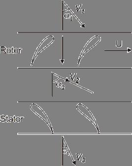
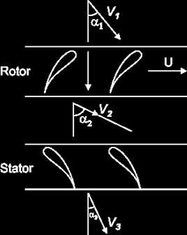
34 Analysis of Axial Compressors Flow Through Stages Velocity Triangles

35 Two basic equations follow immediately from the geometry of the velocity triangles. These are; In which is the axial velocity assumed to be constant throughout the stage. The work done per unit mass is; Velocity Triangles
36 Where; U - blade peripheral velocity w - whirl component - absolute velocity of the air at the rotor entrance - angle of air velocity with the axial direction - relative velocity of air w.r.t. rotor < This turning of air is necessary to provide an increase in the effective flow area It is brought about by the camber of blades.
37 Using velocity triangles we have; Or; This input energy is absorbed usefully in raising the pressure and velocity of the air. A part of it will be spent in overcoming various frictional losses. Regardless of the losses, the input will reveal itself as a rise in the stagnation temperature of the air. If the absolute velocity of the air leaving the stage is made equal to that at the entry,the stagnation temperature rise will also be the static temperature rise of the stage so that;
38 In fact, the stage temperature rise will be less than that given by the above equation owing to three-dimensional effects in the compressor annulus. A factor λ<1 is used which is the measure of the ratio of actual workabsorbing capacity of the stage to its ideal value.
39 and the pressure ratio is given by; Where is the inlet stagnation temperature and is the stage isentropic efficiency;

40 Variation of the work-done factor with number of stages


41 Axial Velocity Distributions The radial distribution of axial velocity is not constant across the annulus but becomes increasingly peaky as the flow proceeds Settles down to a fixed profile at about the fourth stage Axial velocity distributions
42 Degree of Reaction It is a measure of the extent to which the rotor contributes to the increase in the static head of the fluid. Defined as the ratio of the static enthalpy rise in the rotor to that in the whole stage. Variation of Cp over the relevant temperature range will be negligibly small,so, enthalpy ratio is effectively the corresponding temperature ratio. Assuming the simplest case; =>
43 Where - static temperature rise in the rotor - static temperature rise in the stator Since all work input to the stage is transferred to air by means of rotor; we have; => =>
44 But, we have; Therefore => Degree of Reaction;
45 Using earlier equations, we have; => Also, we have;
46 Adding these two equations, we have; Using earlier derived expression, we have; As 50% reaction blading is important in design, we analyze for degree of reaction=0.5
47 It follows from velocity triangles that; i.e. i.e. (Vf is constant) We assumed,it follows that so, a 50% reaction stage is also known as Symmetrical Blading Therefore and has been assumed to be unity for simple analysis.

48 Analysis of Centrifugal Compressors No work is assumed to be done in the diffuser Energy absorbed is determined by inlet and outlet conditions at the impeller Air enters the impeller in axial direction, so initial angular momentum is zero.
49 Vanes have a curved axial portion for smooth entry of air. In the earlier figure, we have; - angle made by the leading edge of the vane with the tangential direction. - relative velocity of air at the inlet - absolute velocity of air at the impeller tip - tangential/whirl component of - Impeller speed at the tip Under ideal conditions, we have; =
50 Since air enters in axial direction; therefore; The energy transfer per unit mass is; Due to inertia, air trapped between the impeller vanes doesn t move round with the impeller. This results in a higher static pressure at the leading face than the trailing face. This prevents air acquiring whirl speed equal to the impeller speed. Slip Factor,σ takes into account this effect;
51 Value of σ lies between In case of slip factor, energy transfer per mass becomes; A widely used expression for σ suggested by Stanitz from the solution of potential flow through impeller passages; where n is the number of vanes.
52 Power Input Factor Power input factor takes into account the effect of disk friction, windage etc. Its value lies between Power Input is therefore more than that required by theoretical expression. Actual Work done per unit mass(power Input) is; where is the power input factor. Adiabatic work done is given by; Using earlier equation, we have;
53 Stagnation Temperature represents the total energy held by the fluid. No energy is added in the diffuser, so, stagnation temperature rise across the impeller is that equal to the whole compressor. If stagnation temperature at the outlet of the diffuser is ;then; => =>

54 - stagnation temperature at the end of ideal (isentropic) compression - stagnation temperature after the actual compression process. - isentropic efficiency
55 Losses in Centrifugal Compressors Frictional losses: A major portion of the losses is due to fluid friction in stationary and rotating blade passages. The flow in impeller and diffuser is decelerating in nature. Therefore the frictional losses are due to both skin friction and boundary layer separation. The losses depend on the friction factor, length of the flow passage and square of the fluid velocity. Incidence losses: During the off-design conditions, the direction of relative velocity of fluid at inlet does not match with the inlet blade angle and therefore fluid cannot enter the blade passage smoothly by gliding along the blade surface. The loss in energy that takes place because of this is known as incidence loss. This is sometimes referred to as shock losses.
56 Clearance and leakage losses: Certain minimum clearances are necessary between the impeller shaft and the casing and between the outlet periphery of the impeller eye and the casing. The leakage of gas through the shaft clearance is minimized by employing glands. The clearance losses depend upon the impeller diameter and the static pressure at the impeller tip. A larger diameter of impeller is necessary for a higher peripheral speed and it is very difficult in the situation to provide sealing between the casing and the impeller eye tip
57 Graphical Depiction of Losses Dependence of various losses with mass flow in a centrifugal compressor;
58 Axial Compressors vs. Centrifugal Compressors Direct Competition in the range of 24 to 90 cubic meters/sec act. Below 33 m3/sec act. the centrifugal is more attractive and above 61 m3/sec act, axial is preferable from economic and design point of view In general, two axial compressor stages are required to produce the same compression as that given by one centrifugal stage. Each axial stage (rotor blade plus the subsequent stator blade row) can develop 1400m to 1700 m of head on air, and slightly less on gases heavier than air. two complete stages together require about 50% of the axial length required by one centrifugal stage.
 have a higher operating region than axial compressor.")
59 Axial Compressors are used for very high flows and low pressure ratios. They (80%-91%) have higher efficiency than centrifugal compressors (75%-87%). Centrifugal compressors are employed for medium flow rates and high pressure ratios. They (around 25%) have a higher operating region than axial compressor.(3%-10%)
60 Reason for High Efficiency of Axial Compressors The gas experiences less drastic changes of direction as it progresses through the stages of an axial machine. The general flow path in an axial compressor is a gradual screw shape through the blading and around the rotor drum in a predominantly axial direction,with minor perturbations through each blade row. In the centrifugal compressor,there are two 180 degrees turns in each stage, in addition to a spiral shaped path in the radial plane of each impeller from the impeller vane inner diameter to the diffuser periphery. the shorter,straighter flow path of the axial results in lower turbulence and turning losses
61 Summary Compressors are devices used to pressurize fluids. Main types of dynamic type compressors are axial and centrifugal compressors. Axial Compressors are used for very high flows and low pressure ratios while centrifugal compressors are used for moderate flow rates and high pressure ratios. In axial compressors, pressure ratio is achieved by passing the fluid through stages while in Centrifugal Compressors,high pressure ratio is achieved by the action of a rotating impeller and subsequent conversion of kinetic energy in static pressure head in the diffuser and impeller. Both compressors have their own advantages and limitations.
62 Acknowledgements I am thankful to Prof. Gautam Biswas and Prof. Subrata Sarkar for their guidance and valuable inputs which were influential in preparing the lecture. I am also thankful to Prof. Ravi Kumar and Prof. Amit Dhiman for their kind support.

63
An Impeller Blade Analysis of Centrifugal Gas Compressor Using CFD
 An Impeller Blade Analysis of Centrifugal Gas Compressor Using CFD Vivek V. Kulkarni Department of Mechanical Engineering KLS Gogte Institute of Technology, Belagavi, Karnataka Dr. Anil T.R. Department
(Refer Slide Time: 2:16)
") Fluid Machines. Professor Sankar Kumar Som. Department Of Mechanical Engineering. Indian Institute Of Technology Kharagpur. Lecture-23. Diffuser and Cavitation. Good morning and welcome you all to this
Fluid Machines. Professor Sankar Kumar Som. Department Of Mechanical Engineering. Indian Institute Of Technology Kharagpur. Lecture-23. Diffuser and Cavitation. Good morning and welcome you all to this
THEORETICAL EVALUATION OF FLOW THROUGH CENTRIFUGAL COMPRESSOR STAGE
 THEORETICAL EVALUATION OF FLOW THROUGH CENTRIFUGAL COMPRESSOR STAGE S.Ramamurthy 1, R.Rajendran 1, R. S. Dileep Kumar 2 1 Scientist, Propulsion Division, National Aerospace Laboratories, Bangalore-560017,ramamurthy_srm@yahoo.com
Applied Fluid Mechanics
 Applied Fluid Mechanics 1. The Nature of Fluid and the Study of Fluid Mechanics 2. Viscosity of Fluid 3. Pressure Measurement 4. Forces Due to Static Fluid 5. Buoyancy and Stability 6. Flow of Fluid and
Inlet Swirl on Turbocharger Compressor Performance
 Inlet Swirl on Turbocharger Compressor Performance Lei Huang, Ying Liu, Hua Chen* National laboratory of Engine Turbocharging Technology, Tianjin, China *corresponding author: Tel.:+86-22-5870-7069; fax:
ASSIGNMENT-1 HYDROPOWER PLANT
 ASSIGNMENT-1 HYDROPOWER PLANT Theory 1. Give classification of hydro electric power plant. 2. Write advantages, disadvantages and application of hydro electric power plant. 3. Explain general layout and
INTRODUCTION 1.0 GENERAL
 1 Chapter INTRODUCTION 1.0 GENERAL Blower is an important class of fluid machine, which has characteristics of transfer of energy between continuous stream of fluid & an element rotating about a fixed
OPTIMIZATION OF SINGLE STAGE AXIAL FLOW COMPRESSOR FOR DIFFERENT ROTATIONAL SPEED USING CFD
 http:// OPTIMIZATION OF SINGLE STAGE AXIAL FLOW COMPRESSOR FOR DIFFERENT ROTATIONAL SPEED USING CFD Anand Kumar S malipatil 1, Anantharaja M.H 2 1,2 Department of Thermal Power Engineering, VTU-RO Gulbarga,
Effect of Inlet Clearance Gap on the Performance of an Industrial Centrifugal Blower with Parallel Wall Volute
 International Journal of Fluid Machinery and Systems DOI: http://dx.doi.org/10.5293/ijfms.2013.6.3.113 Vol. 6, No. 3, July-September 2013 ISSN (Online): 1882-9554 Original Paper (Invited) Effect of Inlet
Compressors. Basic Classification and design overview
 Compressors Basic Classification and design overview What are compressors? Compressors are mechanical devices that compresses gases. It is widely used in industries and has various applications How they
Design and Analysis of a High Pressure Ratio Mixed Flow Compressor Stage
 Design and Analysis of a High Pressure Ratio Mixed Flow Compressor Stage Gaurav Giri 1 and Abdul Nassar. 2 SoftInWay Turbomachinery Solutions Pvt Ltd. 70/10, Cunningham Road, Bangalore, KA, 560052, India
Numerical Fluid Analysis of a Variable Geometry Compressor for Use in a Turbocharger
 Special Issue Turbocharging Technologies 15 Research Report Numerical Fluid Analysis of a Variable Geometry Compressor for Use in a Turbocharger Yuji Iwakiri, Hiroshi Uchida Abstract A numerical fluid
Axial and Centrifugal Compressor Mean Line Flow Analysis Method
 7th AIAA Aerospace Sciences Meeting Including The New Horizons Forum and Aerospace Exposition - January 9, Orlando, Florida AIAA 9- Axial and Centrifugal Compressor Mean Line Flow Analysis Method Joseph
Understanding Centrifugal Compressor Capacity Controls:
 Understanding Centrifugal Compressor Capacity Controls: Richard Stasyshan, CAGI Technical Consultant and the Centrifugal Compressor Section of the Compressed Air & Gas Institiute (CAGI). CAGI and our centrifugal
ASSIGNMENT-1 HYDROPOWER PLANT
 ASSIGNMENT-1 HYDROPOWER PLANT Theory 1. Give classification of hydro electric power plant. 2. Write advantages, disadvantages and application of hydro electric power plant. 3. Explain general layout and
CHAPTER-2 IMPACT OF JET
 CHAPTER-2 IMPACT OF JET FLUID POWER ENGINEERING (2151903) 1. A jet of water of diameter 5cm moving with a velocity of 25 m/sec impinges on a fixed curved plate tangentially at one end at an angle of 30
FLOW CONSIDERATIONS IN INDUSTRIAL SILENCER DESIGN
 FLOW CONSIDERATIONS IN INDUSTRIAL SILENCER DESIGN George Feng, Kinetics Noise Control, Inc., 3570 Nashua Drive, Mississauga, Ontario Vadim Akishin, Kinetics Noise Control, Inc., 3570 Nashua Drive, Mississauga,
Vibration-Free Joule-Thomson Cryocoolers for Distributed Microcooling
 Vibration-Free Joule-Thomson Cryocoolers for Distributed Microcooling W. Chen, M. Zagarola Creare Inc. Hanover, NH, USA ABSTRACT This paper reports on an innovative concept for a space-borne Joule-Thomson
DEFINITIONS. Aerofoil
 Aerofoil DEFINITIONS An aerofoil is a device designed to produce more lift (or thrust) than drag when air flows over it. Angle of Attack This is the angle between the chord line of the aerofoil and the
The Discussion of this exercise covers the following points: Pumps Basic operation of a liquid pump Types of liquid pumps The centrifugal pump.
 Exercise 2-3 Centrifugal Pumps EXERCISE OBJECTIVE In this exercise, you will become familiar with the operation of a centrifugal pump and read its performance chart. You will also observe the effect that
Inlet Influence on the Pressure and Temperature Distortion Entering the Compressor of an Air Vehicle
 Distortion Entering the Compressor of an Air Vehicle P. Hendrick Université Libre de Bruxelles, ULB Avenue F.D. Roosevelt, 50 1050 Brussels BELGIUM patrick.hendrick@ulb.ac.be ABSTRACT One of the possible
AIR EJECTOR WITH A DIFFUSER THAT INCLUDES BOUNDARY LAYER SUCTION
 Engineering MECHANICS, Vol. 20, 2013, No. 3/4, p. 213 220 213 AIR EJECTOR WITH A DIFFUSER THAT INCLUDES BOUNDARY LAYER SUCTION Václav Dvořák* The article deals with axial-symmetric subsonic air-to-air
POWERED FLIGHT HOVERING FLIGHT
 Once a helicopter leaves the ground, it is acted upon by the four aerodynamic forces. In this chapter, we will examine these forces as they relate to flight maneuvers. POWERED FLIGHT In powered flight
Research on Small Wind Power System Based on H-type Vertical Wind Turbine Rong-Qiang GUAN a, Jing YU b
 06 International Conference on Mechanics Design, Manufacturing and Automation (MDM 06) ISBN: 978--60595-354-0 Research on Small Wind Power System Based on H-type Vertical Wind Turbine Rong-Qiang GUAN a,
Computational fluid dynamics analysis of a mixed flow pump impeller
 MultiCraft International Journal of Engineering, Science and Technology Vol. 2, No. 6, 2010, pp. 200-206 INTERNATIONAL JOURNAL OF ENGINEERING, SCIENCE AND TECHNOLOGY www.ijest-ng.com 2010 MultiCraft Limited.
Pump Selection and Sizing (ENGINEERING DESIGN GUIDELINE)
") Guidelines for Processing Plant Page : 1 of 64 Feb 2007 (ENGINEERING DESIGN GUIDELINE) Author: A L Ling Checked by: Karl Kolmetz TABLE OF CONTENT INTRODUCTION Scope 5 General Design Consideration Type
Guidelines for Processing Plant Page : 1 of 64 Feb 2007 (ENGINEERING DESIGN GUIDELINE) Author: A L Ling Checked by: Karl Kolmetz TABLE OF CONTENT INTRODUCTION Scope 5 General Design Consideration Type
COMPUTATIONAL FLOW MODEL OF WESTFALL'S LEADING TAB FLOW CONDITIONER AGM-09-R-08 Rev. B. By Kimbal A. Hall, PE
 COMPUTATIONAL FLOW MODEL OF WESTFALL'S LEADING TAB FLOW CONDITIONER AGM-09-R-08 Rev. B By Kimbal A. Hall, PE Submitted to: WESTFALL MANUFACTURING COMPANY September 2009 ALDEN RESEARCH LABORATORY, INC.
Investigation of Suction Process of Scroll Compressors
 Purdue University Purdue e-pubs International Compressor Engineering Conference School of Mechanical Engineering 2006 Investigation of Suction Process of Scroll Compressors Michael M. Cui Trane Jack Sauls
CFD Analysis and Experimental Study on Impeller of Centrifugal Pump Alpeshkumar R Patel 1 Neeraj Dubey 2
 IJSRD - International Journal for Scientific Research & Development Vol. 3, Issue 2, 21 ISSN (online): 2321-613 Alpeshkumar R Patel 1 Neeraj Dubey 2 1 PG Student 2 Associate Professor 1,2 Department of
Návrh vratného kanálu u dvoustupňového kompresoru Return channel design of the two stage compressor
 Návrh vratného kanálu u dvoustupňového kompresoru Return channel design of the two stage compressor J. Hrabovský, J. Vacula, M. Komárek L. K. Engineering, s.r.o C. Drápela, M. Vacek, J. Klíma PBS Turbo
AE Dept., KFUPM. Dr. Abdullah M. Al-Garni. Fuel Economy. Emissions Maximum Speed Acceleration Directional Stability Stability.
 Aerodynamics: Introduction Aerodynamics deals with the motion of objects in air. These objects can be airplanes, missiles or road vehicles. The Table below summarizes the aspects of vehicle performance
V. A. Sedunin 1, O. V. Komarov 1, V. L. Blinov 1, A. V. Skorokhodov 1 & A. O. Procopets 2. Abstract. 1 Introduction
 Energy Production and Management in the 21st Century, Vol. 1 707 The application of modern Computational Fluid Dynamics techniques for increasing the efficiency and stability of an axial compressor in
A COMPARATIVE STUDY OF MIX FLOW PUMP IMPELLER CFD ANALYSIS AND EXPERIMENTAL DATA OF SUBMERSIBLE PUMP
 IMPACT: International Journal of Research in Engineering & Technology (IMPACT: IJRET) ISSN 2321-8843 Vol. 1, Issue 3, Aug 2013, 57-64 Impact Journals A COMPARATIVE STUDY OF MIX FLOW PUMP IMPELLER CFD ANALYSIS
Selection of gas compressors: part 2
 36 Compressors Selection of gas compressors: part 2 In this multipart series, Eduardo Larralde and Rafael Ocampo aim to provide a comprehensive survey of the current state of the art concerning gas Following
ME1251 THERMAL ENGINEERING UNIT IV AIR COMPRESSORS
 ME1251 THERMAL ENGINEERING UNIT IV AIR COMPRESSORS UNIT-IV 4. 1 CONTENTS TECHNICAL TERMS 4.1 Classification of compressors 4.2 Positive Displacement compressors 4.2.1 Double acting compressor 4.2.2 Diaphragm
Centrifugal Compressor Performance Deviations with Various Refrigerants, Impeller Sizes and Shaft Speeds
 Purdue University Purdue e-pubs International Compressor Engineering Conference School of Mechanical Engineering 2014 Centrifugal Compressor Performance Deviations with Various Refrigerants, Impeller Sizes
AERODYNAMIC CHARACTERISTICS OF NACA 0012 AIRFOIL SECTION AT DIFFERENT ANGLES OF ATTACK
 AERODYNAMIC CHARACTERISTICS OF NACA 0012 AIRFOIL SECTION AT DIFFERENT ANGLES OF ATTACK SUPREETH NARASIMHAMURTHY GRADUATE STUDENT 1327291 Table of Contents 1) Introduction...1 2) Methodology.3 3) Results...5
CHAPTER 9 PROPELLERS
 CHAPTER 9 CHAPTER 9 PROPELLERS CONTENTS PAGE How Lift is Generated 02 Helix Angle 04 Blade Angle of Attack and Helix Angle Changes 06 Variable Blade Angle Mechanism 08 Blade Angles 10 Blade Twist 12 PROPELLERS
Exercise 4-2. Centrifugal Pumps EXERCISE OBJECTIVE DISCUSSION OUTLINE DISCUSSION. Pumps
 Exercise 4-2 Centrifugal Pumps EXERCISE OBJECTIVE Familiarize yourself with the basics of liquid pumps, specifically with the basics of centrifugal pumps. DISCUSSION OUTLINE The Discussion of this exercise
COMPUTER-AIDED DESIGN AND PERFORMANCE ANALYSIS OF HAWT BLADES
 5 th International Advanced Technologies Symposium (IATS 09), May 13-15, 2009, Karabuk, Turkey COMPUTER-AIDED DESIGN AND PERFORMANCE ANALYSIS OF HAWT BLADES Emrah KULUNK a, * and Nadir YILMAZ b a, * New
The effect of back spin on a table tennis ball moving in a viscous fluid.
 How can planes fly? The phenomenon of lift can be produced in an ideal (non-viscous) fluid by the addition of a free vortex (circulation) around a cylinder in a rectilinear flow stream. This is known as
Flow Analysis of Upstream Fluid Flow using Simulation for Different Positions of Optimized Inlet Guide Vane in Centrifugal Air Compressor
 American Journal of Engineering Research (AJER) e-issn : 2320-0847 p-issn : 2320-0936 Volume-03, Issue-02, pp-148-156 www.ajer.org Research Paper Open Access Flow Analysis of Upstream Fluid Flow using
Chapter 2 Pump Types and Performance Data
 Chapter 2 Pump Types and Performance Data Abstract Centrifugal pumps are used for transporting liquids by raising a specified volume flow to a specified pressure level. Pump performance at a given rotor
EFFECT OF LEADING EDGE SWEEP ON THE PERFORMANCE OF A CENTRIFUGAL COMPRESSOR IMPELLER. Abstract 1. INTRODUCTION
 EFFECT OF LEADING EDGE SWEEP ON THE PERFORMANCE OF A CENTRIFUGAL COMPRESSOR Abstract IMPELLER Ch. Sivaji Ganesh 1, *Q. H. Nagpurwala 2, C. S. Bhaskar Dixit 3 1 Student, M. Sc. [Engg.], 2 Professor, 3 Professor
Senior mechanical energy conversion trends
 Senior mechanical energy conversion trends Introduction and Analysis to fan blade profile and CFD Simulation Of An Appropriate Blade Profile for improving energy efficiency HAMED ROSTAMALIZADEH 95742906
Tidal streams and tidal stream energy device design
 Tidal streams and tidal stream energy device design This technical article introduces fundamental characteristics of tidal streams and links these to the power production of tidal stream energy devices.
Study of Secondary Flow Modifications at Impeller Exit of a Centrifugal Compressor
 Open Journal of Fluid Dynamics, 2012, 2, 248-256 http://dx.doi.org/10.4236/ojfd.2012.24a029 Published Online December 2012 (http://www.scirp.org/journal/ojfd) ABSTRACT Study of Secondary Flow Modifications
Aerodynamic Analyses of Horizontal Axis Wind Turbine By Different Blade Airfoil Using Computer Program
 ISSN : 2250-3021 Aerodynamic Analyses of Horizontal Axis Wind Turbine By Different Blade Airfoil Using Computer Program ARVIND SINGH RATHORE 1, SIRAJ AHMED 2 1 (Department of Mechanical Engineering Maulana
The Usage of Propeller Tunnels For Higher Efficiency and Lower Vibration. M. Burak Şamşul
 The Usage of Propeller Tunnels For Higher Efficiency and Lower Vibration M. Burak Şamşul ITU AYOC 2014 - Milper Pervane Teknolojileri Company Profile MILPER is established in 2011 as a Research and Development
How Inlet Conditions Impact Centrifugal Air Compressors
 How Inlet Conditions Impact Centrifugal Air Compressors Richard Stasyshan, CAGI Technical Consultant and the Centrifugal Compressor Section of the Compressed Air & Gas Institiute (CAGI). Centrifugal technology
Development of a High-Flow Centrifugal Compressor Stage
 Development of a -Flow Centrifugal Compressor Stage KAWAKUBO Tomoki : Manager, Turbomachinery & Engine Technology Department, Product Development Center, Corporate Research & Development UNNO Masaru :
Numerical simulation of radial compressor stages with seals and technological holes
 EPJ Web of Conferences 67, 02115 (2014) DOI: 10.1051/ epjconf/ 20146702115 C Owned by the authors, published by EDP Sciences, 2014 Numerical simulation of radial compressor stages with seals and technological
AIAA Brush Seal Performance Evaluation. P. F. Crudgington Cross Manufacturing Co. Ltd. Devizes, ENGLAND
 AIAA 98-3172 Brush Seal Performance Evaluation P. F. Crudgington Cross Manufacturing Co. Ltd. Devizes, ENGLAND BRUSH SEAL PERFORMANCE EVALUATION AIAA-98-3172 P. F. Crudgington Cross Manufacturing Co. Ltd
Lab # 03: Visualization of Shock Waves by using Schlieren Technique
 AerE545 Lab # 03: Visualization of Shock Waves by using Schlieren Technique Objectives: 1. To get hands-on experiences about Schlieren technique for flow visualization. 2. To learn how to do the optics
An Investigation on the Performance Characteristics of a Centrifugal Compressor
 International Journal of Engineering Research and Development e-issn: 2278-067X, p-issn: 2278-800X, www.ijerd.com Volume 10, Issue 11 (November 2014), PP.77-83 An Investigation on the Performance Characteristics
GLOSSARY OF TERMS. Adiabatic Compression Compression process when all heat of compression is retained in the gas being compressed.
 GLOSSARY OF TERMS Absolute pressure Total pressure measured from absolute zero i.e. a perfect vacuum. As a practical matter, gauge pressure plus atmospheric pressure. Absolute temperature Temperature measured
EXPERIMENTAL ANALYSIS OF FLOW OVER SYMMETRICAL AEROFOIL Mayank Pawar 1, Zankhan Sonara 2 1,2
 EXPERIMENTAL ANALYSIS OF FLOW OVER SYMMETRICAL AEROFOIL Mayank Pawar 1, Zankhan Sonara 2 1,2 Assistant Professor,Chandubhai S. Patel Institute of Technology, CHARUSAT, Changa, Gujarat, India Abstract The
Fundamentals of Compressed Air Systems. Pre-Workshop Assignment
 Page 1 In order to ensure that the Compressed Air Challenge Fundamentals of Compressed Air Systems Training is most useful to you, it will be important for you to bring information about your plant s compressed
Aerodynamic Analysis of a Symmetric Aerofoil
 214 IJEDR Volume 2, Issue 4 ISSN: 2321-9939 Aerodynamic Analysis of a Symmetric Aerofoil Narayan U Rathod Department of Mechanical Engineering, BMS college of Engineering, Bangalore, India Abstract - The
Introduction to Pumps
 Introduction to Pumps 1 Introduction to Pumps 1.0 INTRODUCTION There are many different types of pump now available for use in pumped fluid systems. A knowledge of these pump types and their performance
MECHANICAL EQUIPMENTS: COMPRESSORS, PUMPS, SEALS, SPEED DRIVES, CONTROL VALVES & ACTUATORS & SAFETY RELIEF VALVES
 Training Title MECHANICAL EQUIPMENTS: COMPRESSORS, PUMPS, SEALS, SPEED DRIVES, CONTROL VALVES & ACTUATORS & SAFETY RELIEF VALVES Training Duration 5 days Training Venue and Dates REF Mechanical Equipments:
CFD analysis of flow through mixed flow compressor under various operating conditions
 1 CFD analysis of flow through mixed flow compressor under various operating conditions D. Ramesh Rajakumar 1 M.Govardhan 2 S.Ramamurthy 3 Abstract- Performance of mixed flow compressor with un-shrouded
Pre-swirl mechanism in front of a centrifugal compressor: effects on surge line and on unsteady phenomena in surge area
 Pre-swirl mechanism in front of a centrifugal compressor: effects on surge line and on unsteady phenomena in surge area Amélie Danlos 1,*, Pierre Podevin 1, and Michel Toussaint 2 1 Conservatoire National
Optimization of rotor profiles for energy efficiency by using chamber-based screw model
 Optimization of rotor profiles for energy efficiency by using chamber-based screw model Dipl.-Ing. Sven Herlemann, Dr.-Ing. Jan Hauser, Dipl.-Ing. Norbert Henning, GHH RAND Schraubenkompressoren GmbH,
Figure 1 Schematic of opposing air bearing concept
 Theoretical Analysis of Opposing Air Bearing Concept This concept utilizes air bearings to constrain five degrees of freedom of the optic as shown in the figure below. Three pairs of inherently compensated
A centrifugal pump consists of an impeller attached to and rotating with the shaft and a casing that encloses the impeller.
 Centrifugal pump How centrifugal pumps work A centrifugal pump consists of an impeller attached to and rotating with the shaft and a casing that encloses the impeller. In centrifugal pump, liquid is forced
CFD ANALYSIS OF CENTRIFUGAL PUMP IMPELLER HAVING DIFFERENT EXIT BLADE WIDTH, EXIT DIAMETER AND TRAILING EDGE BLADE ANGLE TO ENHANCE PERFORMANCE
 CFD ANALYSIS OF CENTRIFUGAL PUMP IMPELLER HAVING DIFFERENT EXIT BLADE WIDTH, EXIT DIAMETER AND TRAILING EDGE BLADE ANGLE TO ENHANCE PERFORMANCE AmitKumar 1, Prof. Kamal Kumar Jain 2, Dr.R.KDave3, Asst.
CFD ANALYSIS TO INVESTIGATE THE EFFECT OF AXIAL SPACING IN A SINGLE STAGE TRANSONIC AXIAL FLOW COMPRESSOR
 Symposium on Applied Aerodynamics and Design of Aerospace Vehicle (SAROD 2011) November 16-18, 2011, Bangalore, India CFD ANALYSIS TO INVESTIGATE THE EFFECT OF AXIAL SPACING IN A SINGLE STAGE TRANSONIC
Offshore Equipment. Yutaek Seo
 Offshore Equipment Yutaek Seo Flash Gas Compressor (East spar) Dehydration NGL recovery Slug catcher Separator Stabilization Booster compressor Gas export compression (Donghae-1 Platform) May 7 th Gas
Higher Gas Turbine Operation Flexibility by Improved Diffuser Vanes of a Radial Compressor
 Higher Gas Turbine Operation Flexibility by Improved Diffuser Vanes of a Radial Compressor STAR EUROPEAN CONFERENCE 2011 23 March 2011 Amsterdam, The Netherlands Dipl.-Ing. Anis Haj Ayed GmbH, Aachen,
Understanding Lobe Blowers Roots Blowers. Article written by Technical Team of EVEREST GROUP
 Understanding Lobe Blowers Roots Blowers Article written by Technical Team of EVEREST GROUP ompressors and Fans are essentially pumps for gases. Although they differ in construction from liquid handling
Theoretical and Experimental Study on Energy Efficiency of Twin Screw Blowers Compared to Rotary Lobe Blowers
 Theoretical and Experimental Study on Energy Efficiency of Twin Screw Blowers Compared to Rotary Lobe Blowers Mr. Gert an Leuven Team leader Product Development Atlas Copco Airpower n.v., Wilrijk, Belgium
Inlet Influence on the Pressure and Temperature Distortion Entering the Compressor of an Air Vehicle
 Distortion Entering the Compressor of an Air Vehicle P. Hendrick Université Libre de Bruxelles, ULB Avenue F.D. Roosevelt, 50 1050 Brussels BELGIUM patrick.hendrick@ulb.ac.be ABSTRACT One of the possible
Welcome to Aerospace Engineering
 Welcome to Aerospace Engineering DESIGN-CENTERED INTRODUCTION TO AEROSPACE ENGINEERING Notes 4 Topics 1. Course Organization 2. Today's Dreams in Various Speed Ranges 3. Designing a Flight Vehicle: Route
Fundamentals of Turboexpanders Basic Theory and Design
 Fundamentals of Turboexpanders Basic Theory and Design Edited Date: September 16, 2015 Presented By: Mr. James Simms Simms Machinery International, Inc. 2357 A Street Santa Maria, CA 93455 U.S.A. About
A. M. Dalavi, Mahesh Jadhav, Yasin Shaikh, Avinash Patil (Department of Mechanical Engineering, Symbiosis Institute of Technology, India)
") IOSR Journal of Mechanical and Civil Engineering (IOSR-JMCE) ISSN(e) : 2278-1684, ISSN(p) : 2320 334X, PP : 45-49 www.iosrjournals.org Modeling, Optimization & Manufacturing of Vortex Tube and Application
IOSR Journal of Mechanical and Civil Engineering (IOSR-JMCE) ISSN(e) : 2278-1684, ISSN(p) : 2320 334X, PP : 45-49 www.iosrjournals.org Modeling, Optimization & Manufacturing of Vortex Tube and Application
Experimental Analysis on Vortex Tube Refrigerator Using Different Conical Valve Angles
 International Journal of Engineering Research and Development e-issn: 7-067X, p-issn: 7-00X, www.ijerd.com Volume 3, Issue 4 (August ), PP. 33-39 Experimental Analysis on Vortex Tube Refrigerator Using
VGV optimization for performance
 VGV optimization for performance Sara Ling and Ted Sönne Thesis for the Degree of Master of Science Division of Thermal Power Engineering Department of Energy Sciences Faculty of Engineering, LTH Lund
Study on the Shock Formation over Transonic Aerofoil
 Advances in Aerospace Science and Applications. ISSN 2277-3223 Volume 3, Number 2 (2013), pp. 113-118 Research India Publications http://www.ripublication.com/aasa.htm Study on the Shock Formation over
Bioreactor System ERT 314. Sidang /2011
 Bioreactor System ERT 314 Sidang 1 2010/2011 Chapter 2:Types of Bioreactors Week 4 Flow Patterns in Agitated Tanks The flow pattern in an agitated tank depends on the impeller design, the properties of
INDIAN INSTITUTE OF TECHNOLOGY ROORKEE NPTEL NPTEL ONLINE CERTIFICATION COURSE. Refrigeration and Air-conditioning
 INDIAN INSTITUTE OF TECHNOLOGY ROORKEE NPTEL NPTEL ONLINE CERTIFICATION COURSE Refrigeration and Air-conditioning Lecture-07 Vapour Compression Cycle-1 with Prof. Ravi Kumar Department of Mechanical and
V
 THE AMERICAN SOCIETY OF MECHANICAL ENGINEERS -345 E. 47th St., New York, N.Y. 117 The Society shall not be responsible for statements or opinions advanced in papers or discussion at meetings of the Society
S-CO 2 Brayton Recompression Loop Design and Control
 S-CO 2 Brayton Recompression Loop Design and Control 1) Background 2) Recommended Design Features 3) Modeling Strategy IST Model Changes Transient Results Prepared by: Mike Hexemer Advanced Concepts Knolls
DOUBLE-DUCTED FAN CROSS-RELATED APPLICATIONS
 DOUBLE-DUCTED FAN CROSS-RELATED APPLICATIONS [0001] This application claims the benefit of U.S. Provisional Application No. 61/311,672 filed on March 8, 2010, which is incorporated herein by reference
Centrifugal Compressor Configuration, Selection and Arrangement: A User s Perspective
 Centrifugal Compressor Configuration, Selection and Arrangement: A User s Perspective Mark R. Sandberg, P.E. Principal Consulting Engineer Sandberg Turbomachinery Consulting, LLC Montgomery, Texas, USA
Efficiency Improvement of Rotary Compressor by Improving the Discharge path through Simulation
 Purdue University Purdue e-pubs International Compressor Engineering Conference School of Mechanical Engineering 2014 Efficiency Improvement of Rotary Compressor by Improving the Discharge path through
CHAPTER 3 AUTOMOTIVE AIR COMPRESSOR
 30 CHAPTER 3 AUTOMOTIVE AIR COMPRESSOR 3.1 INTRODUCTION A machine providing air at a high pressure is called as an air compressor. Air compressors have been used in industry for well over 100 years because
S.A. Klein and G.F. Nellis Cambridge University Press, 2011
 16-1 A flow nozzle is to be used to determine the mass flow rate of air through a 1.5 inch internal diameter pipe. The air in the line upstream of the meters is at 70 F and 95 psig. The barometric pressure
The Aerodynamic Design and Investigation of Loading Distribution of a Mixed Flow Compressor
 Available online at www.sciencedirect.com ScienceDirect Procedia Engineering 00 (2014) 000 000 www.elsevier.com/locate/procedia APISAT2014, 2014 Asia-Pacific International Symposium on Aerospace Technology,
CFD Analysis of Giromill Type Vertical Axis Wind Turbine
 242 CFD Analysis Giromill Type Vertical Axis Wind Turbine K. Sainath 1, T. Ravi 2, Suresh Akella 3, P. Madhu Sudhan 4 1 Associate Pressor, Department Mechanical Engineering, Sreyas Inst. Engg. & Tech.,
Citation Journal of Thermal Science, 18(4),
,") NAOSITE: Nagasaki University's Ac Title Author(s) Noise characteristics of centrifuga diffuser (Noise reduction by means leading tip) Murakami, Tengen; Ishida, Masahiro; Citation Journal of Thermal Science,
NAOSITE: Nagasaki University's Ac Title Author(s) Noise characteristics of centrifuga diffuser (Noise reduction by means leading tip) Murakami, Tengen; Ishida, Masahiro; Citation Journal of Thermal Science,
Energy Output. Outline. Characterizing Wind Variability. Characterizing Wind Variability 3/7/2015. for Wind Power Management
 Energy Output for Wind Power Management Spring 215 Variability in wind Distribution plotting Mean power of the wind Betz' law Power density Power curves The power coefficient Calculator guide The power
Basic Fluid Mechanics
 Basic Fluid Mechanics Chapter 7B: Forces on Submerged Bodies 7/26/2018 C7B: Forces on Submerged Bodies 1 Forces on Submerged Bodies Lift and Drag are forces exerted on an immersed body by the surrounding
W P C A. Worldwide Pollution Control Association. WPCA-Entergy Increasing Energy Efficiency of Existing Units Seminar January 22, 2014
 Worldwide Pollution Control Association WPCA-Entergy Increasing Energy Efficiency of Existing Units Seminar January 22, 2014 All presentations posted on this website are copyrighted by the Worldwide Pollution
CFD ANALYSIS OF FLOW AROUND AEROFOIL FOR DIFFERENT ANGLE OF ATTACKS
 www.mechieprojects.com CFD ANALYSIS OF FLOW AROUND AEROFOIL FOR DIFFERENT ANGLE OF ATTACKS PRESENTATION OUTLINE AIM INTRODUCTION LITERATURE SURVEY CFD ANALYSIS OF AEROFOIL RESULTS CONCLUSIONS www.mechieprojects.com
ZIN Technologies PHi Engineering Support. PHi-RPT CFD Analysis of Large Bubble Mixing. June 26, 2006
 ZIN Technologies PHi Engineering Support PHi-RPT-0002 CFD Analysis of Large Bubble Mixing Proprietary ZIN Technologies, Inc. For nearly five decades, ZIN Technologies has provided integrated products and
Investigation on Divergent Exit Curvature Effect on Nozzle Pressure Ratio of Supersonic Convergent Divergent Nozzle
 RESEARCH ARTICLE OPEN ACCESS Investigation on Divergent Exit Curvature Effect on Nozzle Pressure Ratio of Supersonic Convergent Divergent Nozzle Shyamshankar.M.B*, Sankar.V** *(Department of Aeronautical
Wind Regimes 1. 1 Wind Regimes
 Wind Regimes 1 1 Wind Regimes The proper design of a wind turbine for a site requires an accurate characterization of the wind at the site where it will operate. This requires an understanding of the sources
Cover Page for Lab Report Group Portion. Pump Performance
 Cover Page for Lab Report Group Portion Pump Performance Prepared by Professor J. M. Cimbala, Penn State University Latest revision: 02 March 2012 Name 1: Name 2: Name 3: [Name 4: ] Date: Section number:
TUTORIAL: SURGE CONTROL AND DYNAMIC BEHAVIOR FOR CENTRIFUGAL GAS COMPRESSORS
 TUTORIAL: SURGE CONTROL AND DYNAMIC BEHAVIOR FOR CENTRIFUGAL GAS COMPRESSORS Rainer Kurz Solar Turbines Incorporated 9330 Skypark Court San Diego, CA 92123 858-694-6652 rkurz@solarturbines.com Robert C.