Mechanical Seal Piping Plans
|
|
|
- Louisa Booth
- 6 years ago
- Views:
Transcription
1 Mechanical Seal Piping Plans Companion Booklet Single Seals Dual Seals Quench Seals Second. Cont. Dual Gas
2 Introduction A primary factor in achieving highly reliable, effective sealing performance is to create the best fluid environment around the seal. Selection of the right piping plan and associated fluid control equipment requires a knowledge and understanding of the seal design and arrangement, fluids in which they operate, and of the rotating equipment. Providing clean, cool face lubrication, effective heat removal, personnel and environmental safety, leakage management and controlling system costs are among the specific factors that must be considered. API has established standardized piping plans for seals that provide industry guidelines for various seal arrangements, fluids and control equipment. The following pages illustrate and describe features of these plans as an aid to help you determine what support system requirements will maximize the performance reliability of your fluid handling rotating equipment application.
3 API 682/ISO standards have default (required) connections and connection symbols for seal chamber and gland plate connections based upon the seal configuration. It is recommended that the latest edition of these standards be reviewed for up-to-date requirements, when these standards are mandated for a piece of rotating equipment. The intent of this booklet is to illustrate the common connections that are utilized for the various piping plans, regardless of the equipment type, and therefore use generic names for connections. The end user and/or equipment manufacturer may have specific requirements that dictate what connections are to be supplied and how they are to be labeled. In the piping plans illustrated, the Flush connection noted for the inboard seal of a dual seal may originate from a number of suitable sources. For example, the Flush for piping plans 11/75 or 32/75 may be the product (Plan 11) or an external source (Plan 32). API682/ISO21049 General Comments
4 Piping Plan Description Plan 01 Single Seals - Internal Flush Plan 02 Single Seals - No Flush, Large Open Bore Plan 11 Single Seals - By-Pass From Discharge With Orifice Plan 12 Single Seals - By-Pass From Discharge With Filter & Orifice Plan 13 Single Seals - Flush Thru Seal Chamber Thru Orifice To Suction Plan 14 Single Seals - By-Pass From Discharge Thru Seal Chamber Back To Suction Plan 21 Single Seals - By-Pass From Discharge Thru Orifice & Heat Exchanger Plan 23 Single Seals - Closed Loop Circulation Thru Heat Exchanger Plan 31 Single Seals - By-Pass From Discharge Thru Orifice & Abrasive Separator Plan 32 Single Seals - External Flush Source To Seal Plan 41 Single Seals - By-Pass From Discharge Thru Abrasive Separator & Heat Exchanger Plan 52 Dual Seals, Unpressurized - External Reservoir Unpressurized Liquid Buffer
5 Plan 53A Dual Seals, Pressurized - External Reservoir Pressurized Liquid Barrier Plan 53B Dual Seals, Pressurized - Liquid Barrier Thru Heat Exchanger & Pressurized By Accumulator Plan 53C Dual Seals, Pressurized - Liquid Barrier Thru Heat Exchanger With Differential Tracking... Piston Accumulator Plan 54 Dual Seals, Pressurized - External Pressurized Barrier System/Source Plan 62 Quench Seals - External Quench On Atmospheric Side Of Seal Plan 65 Single Seals - External Leakage Detection Reservoir Plan 72 Secondary Containment Seals - Low Pressure Buffer Gas Injected To Outer Seal Cavity Plan 74 Dual Gas Seals - Pressurized Dual Gas Seal Thru Conditioning Panel Plan 75 Secondary Containment Seals - Secondary Cont. Seal With Leakage Collection Reservoir Plan 76 Secondary Containment Seals - Secondary Cont. Seal Vented To Flare Or Collection System Piping Plan Description
6 Plan 01 Single Seals Description: Plan 01 is an internal recirculation from the pump discharge area of the pump into the seal chamber, similar to a Plan 11 but with no exposed piping. General: This flush plan should only be used for clean products as dirty products can clog the internal line. Not recommended on vertical pumps. Advantages: No product contamination and no external piping. Advantageous on highly viscous fluids at lower temperatures to minimize the risk of freezing that can occur with exposed piping arrangements.
7 Vent Plugged Internal Flush Porting Vent Plugged Drain Drain Gland End View Gland End View Vent (If Req d.) Plugged No External Flush Quench Optional Plan 01 Single Seals
8 Plan 02 Single Seals Description: Plan 02 is a non-circulating flush plan recommended only where adequate vapor suppression can be assured. Advantages: Solids are not continually introduced into the seal chamber, no external hardware is required, and natural venting occurs when used with a tapered bore seal chamber. General: Ideal with large bore/tapered bore ANSI/ASME B73.1 or ISO 3069 Type C seal chambers or with hot process pumps utilizing a cooling jacket. On the latter services, a Plan 62 with steam quench can also provide some additional cooling.
9 Heating/Cooling Inlet/Outlet Vent Plugged Large Bore Open Throat Or Taper Bore Box Is Recommended Vent Plugged Drain Drain Gland End View Gland End View No Flush Vent (If Req d.) Plugged Quench Optional Ensure Seal Chamber Is Fully Vented Plan 02 Single Seals
10 Plan 11 Single Seals Description: Plan 11 is the most common flush plan in use today. This plan takes fluid from the pump discharge (or from an intermediate stage) through an orifice(s) and directs it to the seal chamber to provide cooling and lubrication to the seal faces. Advantages: No product contamination and piping is simple. General: If the seal is setup with a distributed or extended flush, the effectiveness of the system will be improved.
11 Orifice Flush By-Pass From Discharge Flush Drain Drain Gland End View Gland End View Quench Optional Plan 11 Single Seals
12 Plan 12 Single Seals Description: Plan 12 is similar to Plan 11, except that a strainer or filter is added to the flush line. Advantages: No product contamination and solids are removed from the flush stream keeping the seal clean. General: If the seal is setup with a distributed or extended flush, the effectiveness of the system will be improved. This plan should be equipped with a differential pressure indicator or alarm to alert the user that the filter or strainer is clogged.
13 Strainer Or Filter Flush By-Pass From Discharge Orifice Cleanout Trap Flush Drain Drain Gland End View Gland End View Quench Optional Plan 12 Single Seals
14 Plan 13 Single Seals Description: In a Plan 13, the flow exits the seal chamber through an orifice and is routed back to pump suction. Advantages: With a Plan 13, it is possible to increase or decrease seal chamber pressure with proper sizing of the orifice and throat bushing clearance. General: Typically Plan 13 is used on vertical turbine pumps since they have the discharge at the top of the pump where the seal is located. Because of the difference in flow patterns, Plan 13 is not as efficient in removing heat as a Plan 11 and thus requires a higher flow rate.
15 Orifice Flush Outlet Return To Suction Flush Outlet Drain Drain Gland End View Gland End View Quench Optional Plan 13 Single Seals
16 Plan 14 Single Seals Description: Plan 14 is a combination of Plans 11 and 13. Flush is taken off of pump discharge, sent to the seal chamber, and piped back to pump suction. General: Often used on vertical pumps to provide adequate flow and vapor pressure margin independent of throat bushing design. Advantages: Cooling can be optimized with the flush directed at the seal faces. Plan allows for automatic venting of the seal chamber.
17 By-Pass From Discharge Orifice Flush Outlet Orifice Return To Suction Flush Inlet (Alt. into Gland) Flush Outlet Drain Drain Flush Inlet Gland End View Gland End View Quench Optional Plan 14 Single Seals
18 Plan 21 Single Seals Description: Plan 21 is a cooled version of Plan 11. The product from pump discharge is directed through an orifice, then to a heat exchanger to lower the temperature before being introduced into the seal chamber. Advantages: Process fluid cools and lubricates the seal, therefore no dilution of process stream. Cooling improves lubricity and reduces the possibility of vaporization in the seal chamber. General: Plan 21 is not a preferred plan, either by API or many users, due to the high heat load put on the heat exchanger. A Plan 23 is preferred.
19 Orifice Vent, Normally Closed Heat Exchanger Vent, Normally Closed By-Pass From Discharge Cooling Water Connections Flush Flush Drain Drain, Norm. Closed Temperature Indicator Drain Gland End View Gland End View Quench Optional Plan 21 Single Seals
20 Plan 23 Single Seals Description: Plan 23 is a closed loop system using a pumping ring to circulate product through a heat exchanger and back to the seal chamber. Advantages: More efficient than a Plan 21 and less chance of heat exchanger fouling. Reduced temperature improves lubricity and improves vapor pressure margin. General: Preferred plan for hot applications. Close clearance throat bushing is recommended to reduce mixing of hot product with cooler closed loop system fluid.
21 Vent, Normally Closed Heat Exchanger Cooling Water Vent, Normally Closed Flush Outlet (Alt. from Gland Conn.) Cooling Water Connections Flush Outlet Shown For CW Shaft Rotation Flush Inlet Cooling Water Drain, Norm. Closed Pumping Ring Drain Temperature Indicator Drain Flush Inlet Gland End View Gland End View Quench Optional Plan 23 Single Seals
22 Plan 31 Single Seals Description: Plan 31 is a variation of Plan 11, where an abrasive separator is added to the flush line. In this plan, the product is introduced to the abrasive separator from the discharge of the pump, clean flush is piped from the separator to the seal chamber and solids are returned to the pump suction. Advantages: Unlike a strainer or filter, the abrasive separator does not require cleaning. Solids are removed from the flush stream keeping the seal clean. General: This plan should be used for services containing solids that have a specific gravity at least twice that of the process fluid. Typically the separator requires a minimum pressure differential of 15 psi to operate properly. Note: A abrasive separator is subject to wear and must be maintained regularly to ensure efficient operation.
23 Flush By-Pass From Discharge Return To Suction Orifice (optional) Abrasive/ Cyclone Separator Drain Gland End View Flush Drain Gland End View Quench Optional Plan 31 Single Seals
24 Plan 32 Single Seals Description: Plan 32 uses a flush stream brought in from an external source to the seal. This plan is almost always used in conjunction with a close clearance throat bushing. Advantages: The external flush fluid, when selected properly, can result in vastly extended seal life. General: When an outside flush source is used, concerns regarding product dilution and/or economics must be considered by the user. Source pressure must be maintained a minimum of 15 psig above maximum seal chamber pressure.
25 Flow Control Valve Pressure Indicator Flow Indicator (Optional) Strainer/Filter Valve, Normally Open Clean/Compatible External Flush Source Flush Close Clearance Bushing Drain Clean Out Trap Temperature Indicator (Optional) Gland End View Flush Check Valve Drain Gland End View Quench Optional Plan 32 Single Seals
26 Plan 41 Single Seals Description: Plan 41 is a combination of Plan 21 and Plan 31. In Plan 41, product from pump discharge is first put through an abrasive separator and then to the heat exchanger before being introduced to the seal chamber. Advantages: Solids are removed and product temperature is reduced to enhance the seal s environment. General: Plan 41 is typically used on hot services with solids; however, depending on the temperature of the process, operating costs can be high. This plan should be used for services containing solids that have a specific gravity at least twice that of the process fluid. Typically the separator requires a minimum pressure differential of 15 psi to operate properly.
27 Abrasive/Cyclone Separator Heat Exchanger Vent, Normally Closed By-Pass From Discharge Return To Suction Flush Cooling Water Connections Drain Drain, Norm. Closed Temperature Indicator Flush Gland End View Quench Optional Drain Gland End View Plan 41 Single Seals
28 Plan 52 Dual Seals, Unpressurized Description: Plan 52 uses an external reservoir to provide buffer fluid for the outer seal of an unpressurized dual seal arrangement. Advantages: In comparison to single seals, dual unpressurized seals can provide reduced net leakage rates as well as redundancy in the event of a primary seal failure. General: Cooling coils in the reservoir are available for removing heat from the buffer fluid. Plan 52 is often used where process fluid contamination can not be tolerated.
29 Note: Tangential porting is unidirectional. Gland is illustrated for CCW shaft rotation from drive end. Make-Up Buffer Liquid, Normally Closed Vent, Normally Open Level Switch (Low) Orifice Check Valve Pressure Switch (High) Pressure Indicator Reservoir To Collection System Sight Level Gauge Primary Seal Flush (if reqd.) Buffer Outlet Pumping Ring Buffer Inlet Cooling Water Out Gland End View Buffer Liquid Drain, Normally Closed Cooling Coils Cooling Water In Buffer Outlet Flush Buffer Inlet Gland End View Plan 52 Dual Seals, Unpressurized
30 Plan 53A Dual Seals, Pressurized Description: Plan 53A uses an external reservoir to provide barrier fluid for a pressurized dual seal arrangement. Reservoir pressure is produced by a gas, usually nitrogen. Flow is induced by a pumping ring. General: Heat is dissipated by reservoir cooling coils. Barrier fluid is subject to gas entrainment at pressures/temperatures above 300 psi/250 0 F. Advantages: Reservoir size can be optimized dependent on flow rate. Wear particles settle to bottom of reservoir and don t get recirculated.
31 Note: Tangential porting is unidirectional. Gland is illustrated for CCW shaft rotation from drive end. Flush (when specified) Pumping Ring Make-Up Barrier Liquid Fill, Normally Closed Barrier Outlet Pressure Source, Normally Open Level Switch (Low) Check Valve Barrier Inlet Cooling Water Out Gland End View Barrier Liquid Drain, Normally Closed Pressure Indicator Pressure Reservoir Cooling Coils Cooling Water In Pressure Switch (Low) Sight Level Gauge Barrier Outlet Barrier Inlet Gland End View Plan 53A Dual Seals, Pressurized
32 Plan 53B Dual Seals, Pressurized Description: Plan 53B, previously termed 53 Modified, uses an accumulator to isolate the pressurizing gas from the barrier fluid. A heat exchanger is included in the circulation loop to cool the barrier fluid. Flow is induced by a pumping ring. Advantages: Should the loop be contaminated for any reason, the contamination is contained within the closed circuit. The make-up system can supply barrier fluid to multiple dual pressurized sealing systems. General: The bladder accumulator isolates the pressurizing gas from the barrier fluid to prevent gas entrainment. The heat exchanger can be a water-cooled unit, an air-cooled unit, or utilize finned tubing based upon the system heat load.
33 Note: Tangential porting is unidirectional. Gland is illustrated for CCW shaft rotation from drive end. Flush (when specified) Barrier Outlet Pumping Ring Vent, Normally Closed Valve, Normally Open Barrier Inlet Heat Exch. Gland End View Drain, Normally Closed Cooling Water Connections Pressure Switch (Low) Pressure Indicator Valve, Normally Open Barrier Outlet Barrier Inlet Gland End View Bladder Charge Connection Accumulator Barrier Liquid Fill, Normally Closed Plan 53B Dual Seals, Pressurized
34 Plan 53C Dual Seals, Pressurized Description: Plan 53C uses a piston accumulator to provide pressure to the system. It uses a reference line from the seal chamber to provide a constant pressure differential over the chamber s pressure. A water- or air-cooled heat exchanger provides for barrier fluid cooling. Flow is induced by a pumping ring. Advantages: Provides a tracking system to maintain barrier pressure above seal chamber pressure. General: The heat exchanger can be a water-cooled unit, an air-cooled unit, or utilize finned tubing based upon the system heat load. The reference line to the accumulator must be tolerant of process contamination without plugging.
35 Seal Chamber Pressure Ref. Line (Alt. In Seal Chamber) Level Indicator Piston Accumulator Barrier Outlet Pumping Ring Barrier Inlet Gland End View Barrier Fluid Make-Up Temperature Indicator Pressure Indicator Pressure Switch (Low) Note: Tangential porting is uni-directional. Gland is illustrated for CCW shaft rotation from drive end. Valve, Normally Open Cooling Water Connections Heat Exchanger Drain, Normally Closed Seal Chamber Pressure Reference Line Barrier Outlet Barrier Inlet Gland End View Plan 53C Dual Seals, Pressurized
36 Plan 54 Dual Seals, Pressurized Description: Plan 54 utilizes an external source to provide a clean pressurized barrier fluid to a dual seal. Advantages: Can provide pressurized flow to multiple seal installations to reduce costs. Positively eliminates fugitive emissions to atmosphere. General: Plan 54 systems can be custom engineered to suit application or specific plant requirements. Systems can range from the direct connection from other process streams to complex lubrication systems.
37 Flush (when specified) Barrier Outlet Barrier Inlet External Pressurized Barrier Source/System Gland End View Barrier Outlet Barrier Inlet Gland End View Plan 54 Dual Seals, Pressurized
38 Plan 62 Quench Seals Description: Plan 62 is a common plan to improve the environment on the atmospheric side of single seals by quenching with steam, nitrogen or water. Advantages: Plan 62 is a low cost alternative to tandem seals. The quench prevents or retards product crystallization or coking. Quenches can also provide some cooling. General: Typical applications include; steam quenches on hot services to retard coking; nitrogen quenches on cold or cryogenic service to prevent icing; or water quench to prevent crystallization or accumulation of product on the atmospheric side of the seal.
39 Steam Quench Illustrated Steam Trap Used On Steam Quench Check Valve Quench Source Valve, Normally Open Pressure Indicator Valve, Normally Open Quench Inlet Flush (when specified) Drain Outlet Gland End View Flush Quench Steam Deflector Close Clearance Bushing Drain Gland End View Plan 62 Quench Seals
40 Plan 65 Single Seals Description: Plan 65 is a liquid leakage detection plan normally used for single seals. It utilizes a level switch on a reservoir to set off an alarm when excess leakage is detected. Advantages: Provides an alarmed indication of excessive seal leakage that can shutdown equipment if necessary. General: The system includes a loop to by-pass the orifice to prevent high pressure on the atmospheric side of the seal. The gland throttle bushing design should be consistent with the fluid s properties. Gland throttle bushing designs can vary from fixed designs to segmented bushings.
41 Throttle Bushing Gland End View By-Pass Line Flush (when specified) Drain Valve, Normally Open Leakage Reservoir Orifice Level Switch (High) Flush Drain, Normally Open To Liquid Collection System Drain Gland End View Plan 65 Single Seals
42 Plan 72 Secondary Containment Seals Description: Plan 72 for secondary containment uses an external low pressure buffer gas, usually nitrogen, regulated by a control panel that injects it into the outer seal cavity. General: Plan 72 is normally used with Plan 75 for primary seal leakage that is condensing, or with Plan 76 for non-condensing leakage. Advantages: Introduction of a buffer gas like nitrogen reduces fugitive emissions, prevents icing on cold applications, and provides for some cooling to the outboard seal.
43 A: Leakage management piping depending upon process fluid properties. Flush (when specified) Gas Buffer Supply Inlet Vent A Drain A Gas Buffer Supply Outlet To Seal Gas Buffer Inlet Gland End View System Components Shut Off Valve, Norm. Open Coalescing Filter Pressure Regulator Pressure Indicator Pressure Switch Flow Indicator Check Valve Shut Off Valve, Norm. Open Orifice Vent A Flush Gas Buffer Inlet Drain A Gland End View Plan 72 Secondary Containment Seals
44 Plan 74 Dual Gas Seals Description: Plan 74 provides a pressurized gas, typically nitrogen, to dual gas seals through the use of a control panel that removes moisture, filters the gas, and regulates the barrier pressure. Advantages: Lower costs and maintenance than systems used on dual pressurized liquid systems. Leakage to atmosphere is an inert gas. General: The barrier gas is usually a pressurized nitrogen line. For higher pressure applications the system pressure can be supplemented with a gas pressure booster/amplifier. Typically dry-running, non-contacting, gas lubricated seals are used with this plan.
45 System Components Shut Off Valve, Norm. Open Coalescing Filter Pressure Indicator Pressure Regulator Flow Indicator Pressure Switch Check Valve Shut Off Valve, Norm. Open 1 8 Gas Barrier Inlet Gas Barrier Supply Source Inlet Gland End View Gas Barrier Supply Outlet To Seal Gas Barrier Inlet Gland End View Plan 74 Dual Gas Seals
46 Plan 75 Secondary Containment Seals Description: Plan 75 is a collection system used with secondary containment seals for process fluid that will condense at lower temperatures or is always in a liquid state. General: Plan 75 can be used in conjunction with a gas purge from Plan 72. Typically dry-running, contacting secondary containment seals are used with this plan. Advantages: The collection reservoir contains a pressure gauge and a high pressure switch to indicate a build up in pressure from excessive primary seal leakage or failure.
47 To Vapor Collection System Orifice Pressure Indicator Flush When Specified Gland End View Drain, Norm. Open Pressure Switch (High) Isolation Valve Vent Plugged Flush Drain Valve Normally Closed Level Indicator Drain Leakage Collection Reservoir Level Switch (High) Gland End View Plan 75 Secondary Containment Seals
48 Plan 76 Secondary Containment Seals Description: Plan 76 is a system to divert non-condensing primary seal leakage to a flare or vapor recovery system. Advantages: Lower initial and maintenance costs than dual unpressurized seals using a Plan 52. General: Plan 76 can be used in conjunction with a gas purge from Plan 72. Can be used with dry-running, contacting or non-contacting secondary containment seals.
49 Pressure Indicator Normally Open Pressure Switch (High) To Flare Or Vapor Recovery System Orifice Vent Flush Flush (when specified) Vent To Drain, Norm. Closed Gland End View Normally Closed Drain Plugged Gland End View Plan 76 Secondary Containment Seals
50 Best Piping Practices h Minimize piping line losses. h Minimum 1/2 piping or 5/8 tubing. h Use large radius bends. h Tangential outlet ports. h Verify shaft rotation direction. h Slope horizontal runs upward. h Install drain at lowest piping point. h Flush is recommended whenever possible. h Use forced circulation where possible. h Cooling is recommended for buffer/ barrier fluid. h Always properly vent the system prior to start-up. h Always verify pressure and/or level switch set points. h Check system for leaks. h Contact John Crane for buffer/barrier fluid recommendation.
51 * 18"-24" Normal Conditions 3'-5' If Hot Stand-By Promotes Thermosyphon Effect High Point Vent Normally Open 1/4 per foot Min. Slope Shaft Gland Flush Flush Outlet To Inlet Heat Exchanger 3-5 * 3-5 * Vertical Equipment CW Shaft Rot. Shown Horizontal Equipment Flush Inlet To Seal 3 Max. Low Point Drain Valve Best Piping Practices Single Seals - Plan 23 Illustrated
52 Best Piping Practices Dual Seals - Plan 53A Illustrated Horizontal Equipment 3 Max. 1/4 per foot Min. Slope Barrier Outlet CW Shaft Rot. Shown Barrier Inlet Drain Valve Low Point Drain Valve Barrier Inlet Vertical Equipment Shaft Gland

53 John Crane offers a full range of standard and custom engineered Lemco brand seal support systems. All systems are designed and built to industry standards including ANSI B31.3 for piping; API 610, 682 and 614 for system design; IEC, NEMA, NEC, or CSA for instrumentation and electrical; and pressure vessels in accordance with ASME requirements. John Crane, Lemco Products Tulsa, Oklahoma, USA tel: fax: Lemco Seal Support Systems
54 Lemco Seal Support API 682/ISO Products API 682 Plans 52 and 53A Reservoirs: These reservoirs are designed for the Refinery, Petrochemical, and Chemical Industries. API 682 Plan 53B: A dual pressurized system that eliminates direct gas contact with the barrier liquid. API 682 Plan 53C: This system is ideal for applications that have fluctuating pressures. API 682 Plan 72 Gas Control Panel: Used in a dual unpressurized seal arrangement where the secondary seal is dry-running. API 682 Plan 75 Condensate Collection Reservoir: Used in a dual unpressurized seal arrangement where the secondary seal is dryrunning. API 682 Plan 76 Vent to Flare Panel: Used in a dual unpressurized seal arrangement where the secondary seal is dry-running. API 682 Plan 74 Gas Control Panel: Used on non-contacting, dual pressurized seals, this system filters, regulates and monitors the gas supply, typically nitrogen, used to lubricate the seals.


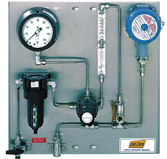
55 API 682 Plan 52/53A Reservoirs API 682 Plan 53B Reservoirs API 682 Plan53C Reservoir API 682 Plan 72/74 Gas Control Panel Lemco Seal Support Systems


56 Lemco Seal Support Systems Compressor Gas Panels and Seal Oil Systems Type 28 Gas Panel Gas Conditioning Unit Seal Oil System with Air- Cooled Heat Exchanger


57 Heat Exchangers and Auxiliary Equipment Water-Cooled Heat Exchanger Air-Cooled Heat Exchanger Leakage Detection Systems Abrasive Separators Lemco Seal Support Systems


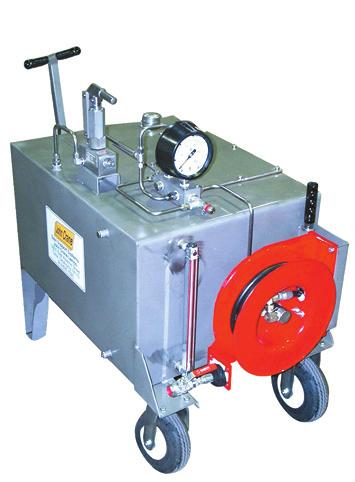
58 Lemco Seal Support Systems Non-API Reservoirs and Mobile Refill Carts RE-1203/RE-1205 RE-1603 RE-1518 RE Gallon
59 ORIFICE BLOCK VALVE CHECK VALVE FILTER/STRAINER HEAT EXCHANGER COALESCING FILTER PSH PSL PRESSURE SWITCH HIGH PRESSURE SWITCH LOW FLOW REGULATING VALVE PRESSURE CONTROL VALVE RESERVOIR PISTON ACCUMULATOR PI TI FI PRESSURE INDICATOR TEMPERATURE INDICATOR FLOW INDICATOR LI LEVEL INDICATOR LSH LEVEL SWITCH HIGH LSL LEVEL SWITCH LOW CYCLONE SEPARATOR BLADDER ACCUMULATOR FM FLOW METER FSH FLOW SWITCH HIGH Instrumentation References
60 User Notes:
61
62 Europe Latin America Middle East, Africa, Asia North America Slough, UK Sao Paulo, Brazil Dubai, United Arab Emirates Morton Grove, Illinois USA Tel: Tel: Tel: SEALING Fax: Fax: Fax: Tel: Fax: For your nearest John Crane facility, please contact one of the locations above. If the products featured will be used in a potentially dangerous and/or hazardous process, your John Crane representative should be contacted prior to their selection and use. In the interest of continuous development, John Crane Companies reserve the right to alter designs and specifications without prior notice. It is dangerous to smoke while handling products made from PTFE. Old and new PTFE products must not be incinerated John Crane Inc. Print 9/06 ISO 9001, ISO 14001, ISO/TS Certified MSPP Booklet
Mechanical Seal Piping Plans
 Mechanical Seal Piping Plans Single Seals plans 01, 02, 11, 13, 14, 21, 23, 31, 32, 41 Dual Seals plans 52, 53A, 53B, 53C, 54 Quench Seals plans 62, 65 Gas Seals plans 72, 74, 75, 76 Mechanical Seal Piping
Mechanical Seal Piping Plans
 Mechanical Seal Piping Plans Single Seals plans 01, 02, 03, 11, 13, 14, 21, 23, 31, 32, 41 Dual Seals plans 52, 53A, 53B, 53C, 54, 55 Quench Seals plans 62, 65A, 65B, 66A, 66B Gas Seals plans 72, 74, 75,
TYPE ECS SEAL METAL BELLOWS DRY-RUNNING SECONDARY CONTAINMENT Technical Specification
 Low Temperature Design A Spacer Ring B Compression Ring C Retaining Ring D Wave Spring E O-ring F ent/drain Connection G Seat/Mating Ring H Insert I Bellows Assembly J Housing A K Spacer B F G H I C D
Circulation Systems for Single and Multiple Seal Arrangements
 Circulation Systems for Single and Multiple Seal Arrangements Gordon Buck and Ralph Gabriel, John Crane This discussion opens a three-part series covering mechanical seal piping plans that provide guidelines
TYPE 3710 CARTRIDGE SPLIT SEAL Technical Specification
 A Mating Ring B Mating Ring/ Retaining Ring C Mating Ring/ Clamp Ring D Mating Ring Adapter E Primary Ring F Primary Ring/ Retaining Ring G Finger Springs H Spring Retainer I Gland O-ring J Flat Gasket
FIELD TROUBLESHOOTING COMMON MECHANICAL SEAL PIPING PLANS. Michael Huebner Principal Engineer Flowserve Corporation Pasadena, TX USA
 FIELD TROUBLESHOOTING COMMON MECHANICAL SEAL PIPING PLANS Michael Huebner Principal Engineer Flowserve Corporation Pasadena, TX USA Ronald Hurst Manager, Application Engineering Flowserve Corporation Pasadena,
Installation Operation Maintenance
 682 Seal Cooler New generation seal cooler to meet and exceed the seal cooler requirements stated in the 4th Edition of API Standard 682 Installation Operation Maintenance Experience In Motion Description
API Piping Plan 62: A Reliable Quench System
 MAY05PUMPS&SYSp24-33 4/19/05 4:04 PM Page 24 It s one of the few methods you have to control the environment outside a mechanical seal. By Keith Schindler, PE, Schindler Engineering, Inc., and Paul McMahan,
TYPE 2800E EXTERNALLY MOUNTED, GAS LUBRICATED, NON-CONTACTING, DOUBLE CARTRIDGE SEAL
 A Seat/Mating Ring B Face/Primary Ring (inboard) C Spring D Face/Primary Ring (outboard) E O-Ring F Drive Collar G Setting Ring H Sleeve TYPE 2800E B A D C H E Spiral Groove Technology G F Product Description
Improve Reliability of Turbomachinery Lubrication and Sealing Systems
 Improve Reliability of Turbomachinery Lubrication and Sealing Systems Fisher Pressure Control Solutions For Turbomachinery Applications Protect the integrity of your Turbomachinery support system Turbomachinery
Installation Instructions
 Installation Instructions BW Seals Uniseal Series Cartridge metal bellows single and dual seals Experience In Motion Description The Uniseal metal bellows seal series consists of: Uniseal I - Single seals
TYPE 28 DRY-RUNNING, NON-CONTACTING GAS SEALS Technical Specification
 Standard Unidirectional Groove Design Optional Bidirectional Groove Design Product Description Type 28 compressor dry-running gas seals have been the industry standard since the 197s for gas-handling turbomachinery.
Application of Double Vs Tandem Dry gas seal Advantages.
 Application of Double Vs Tandem Dry gas seal Advantages. John Sears WW Director, Compressor Products. Flowserve Corporation. Unit #2207, 220 Fisher Street, SE, Calgary, Alberta, T2H 2H8 Canada; World Wide
Beyond Switches for Pump Monitoring:
 Beyond Switches for Pump Monitoring: What Changed with API Standard 682 Beyond Switches for Pump Monitoring: What Changed with API Standard 682 API Standard 682 (Plans 52, 53 A, B, and C for dual seal
Produc. Atmosph. here
 Mechanical Seal Selection API 682 (2 nd Edition) Table Of Contents: 1) Seal Selection Methods 2) Fundamentals Of Sealing 3) Introduction To API 682 (2 nd Edition) 4) Several Important Terms That Used In
Dry Gas Seal Rack CH-3185 Schmitten Tel Mail:
 Dry Gas Seal Rack CH-3185 Schmitten Tel. +41 26 497 55 66 Mail: info@felcon.ch Usually, compressor modifications are carried out because of adaptations to new operating parameters. However, in cases of
OVERVIEW OF API 682 AND ISO 21049
 OVERVIEW OF API 682 AND ISO 21049 by Michael B. Huebner Staff Engineer Flowserve Corporation Deer Park, Texas Michael B. Huebner is a Staff Engineer at Flowserve Corporation, Flow Solutions Division, in
Please contact AESSEAL Systems division for further details. Tel: +44 (0)
") API PIPING PLANS To check out mechanical seal flushing arrangements and piping plans, I have consistently found this to be the most useful and permanent pocket-sized document. This high-quality booklet
API PIPING PLANS To check out mechanical seal flushing arrangements and piping plans, I have consistently found this to be the most useful and permanent pocket-sized document. This high-quality booklet
Installation, Operation, & Maintenance Manual NX Seal Cooler
 Installation, Operation, & Maintenance Manual NX Seal Cooler 1 1. INTRODUCTION 1.1 About this Manual This manual is intended to ensure a safe installation and operation of the NX sealcooler. All involved
Compressor Seal Replacement and Upgrades SERVICES
 Compressor Seal Replacement and Upgrades SERVICES Compressor Seal Upgrades An Elliott Group compressor seal upgrade increases seal reliability and reduces process gas leakage to improve overall efficiency.
OVERVIEW OF API 682 SECOND EDITION
 OERIEW O A 682 SECOND EDITION by Michael B. Huebner Staff Engineer lowserve Corporation Deer Park, Texas Michael Huebner is a Staff Engineer at lowserve Corporation, low Solutions Division, in Deer Park,
API PIPING PLANS. AESSEAL Global Locations
 AESSEAL Global Locations API PIPING PLANS AESSEAL plc, Rotherham, UK Tel: +44 (0) 1709 369966 rotherham@aesseal.com AESSEAL (MCK) Ltd, Lisburn, UK Tel: +44 (0) 2892 669966 salesmck@aesseal.co.uk AESSEAL
Successful Implementation of Dry Gas Seal in High Pressure Recycle gas Compressor at Hydrocracker & Effect of Gas composition on DGS Performance
 Successful Implementation of Dry Gas Seal in High Pressure Recycle gas Compressor at Hydrocracker & Effect of Gas composition on DGS Performance Why - Dry Gas Seal??? M&I shutdown and Catalyst replacement
TYPE 7828G/7828GD 7800 SERIES UNIVERSAL VESSEL SEAL Technical Specification
 A Face/Primary Ring B Seat/Mating Ring C O-Ring D Disc E Sleeve F Retaining Sleeve G Retaining Clip G D C E F C A B Patent numbers: 5,938,206 and 6,142,478 Product Description The universal vessel seal
TYPE 7800 SERIES 7848D/7848W UNIVERSAL VESSEL SEAL Technical Specification
 A Face/Primary Ring B Seat/Mating Ring C O-ring D Disc E Sleeve F Retaining Sleeve D C E C F A B Product Description The Universal Vessel Seal 7800 Series is a modular cartridge seal for use in a wide
Design Enhancements on Dry Gas Seals for Screw Compressor Applications
 VDI-Berichte Nr. 1932, 2006 B 8 331 Design Enhancements on Dry Gas Seals for Screw Compressor Applications Dipl.-Ing C. Kirchner, Flowserve Dortmund GmbH & Co KG, Dortmund Introduction The development
Copyright, 2005 GPM Hydraulic Consulting, Inc.
 Troubleshooting and Preventive Maintenance of Hydraulic Systems Learning to Read the Signs of Future System Failures Instructed by: Al Smiley & Alan Dellinger Copyright, 2005 GPM Hydraulic Consulting,
Hydraulic Reliability & Preventive Maintenance Report
 Hydraulic Reliability & Preventive Maintenance Report The following is a report of the test, procedures and recommendations for the in-plant press. This information was recorded on May 10 th and 11 th,
APPLICATION ENGINEERING API 682
 PPLITION ENGINEERING 682 Mechanical Seals & Supply Systems for: Refinery & Petrochemical pplications Selection and application recommendations according to 682. E 3 / 05-2014 Step I ategory ategory 1 ategory
API 682 Mechanical Seals. Swagelok Eastern Australia & New Zealand
 API 682 Mechanical Seals Swagelok Eastern Australia & New Zealand API 682 Mechanical Seals Overview Previous projects completed o Plan 53A o Plan 72 / 76 o Plan 74 API 682 Mechanical Seals Overview What
Bulletin TCR-104 & 109 Filling and adding to the Glycol pressure system
 Bulletin 061013 TCR-104 & 109 Filling and adding to the Glycol pressure system 1. Glycol System and air On this model the glycol system is a closed system, the glycol is not exposed to the air. No external
LAKOS Waterworks. PWC Series Sand Separators. Installation & Operation Manual LS-829 (10/12)
") LAKOS Waterworks PWC Series Sand Separators Installation & Operation Manual LS-829 (10/12) Table of Contents Separator Operation... 3 Individual Model Details.... 4 Flow vs. Pressure Loss Chart 4 Installation
LAKOS Waterworks PWC Series Sand Separators Installation & Operation Manual LS-829 (10/12) Table of Contents Separator Operation... 3 Individual Model Details.... 4 Flow vs. Pressure Loss Chart 4 Installation
KAYDON RING & SEAL, INC.
 KAYDON RING & SEAL, INC. K-DGS Series Dry Gas Seals KAYDON K-DGS Dry Gas Seals K-DGS Configurations Single Seal (K-DGS) Compact and economical, the single seal configuration is recommended for non-toxic
CONTAINMENT SEALS FOR API 682 SECOND EDITION
 CONTAINMENT SEALS FOR API 682 SECOND EDITION by Peter E. Bowden Technical Services Manager John Crane EAA Manchester, England and Chris J. Fone Director of Technical Services John Crane EAA Slough, England
Берг АБ Тел. (495) , факс (495) Turning Ideas Into Engineered Solutions KAYDON RING & SEAL, INC.
 , факс (495) Turning Ideas Into Engineered Solutions KAYDON RING & SEAL, INC.") Turning Ideas Into Engineered Solutions RING & SEAL, INC. K-CBS Series Circumferential Barrier Seals Kaydon s high performance circumferential barrier seals back up DGS systems with performance & economy.
Turning Ideas Into Engineered Solutions RING & SEAL, INC. K-CBS Series Circumferential Barrier Seals Kaydon s high performance circumferential barrier seals back up DGS systems with performance & economy.
Safety Selector Valves Dual Pressure Relief Device System
 ANDERSON GREENWOOD Features and enefits Provides a safe, efficient method of switching from an active pressure relief device to a standby, maintaining system overpressure protection regardless of Safety
Installation Instructions
 Installation Instructions High Temperature Metal Bellows Seals Cartridge seals with flexible graphite gaskets BXH, BXHH, BXRH, BRC, GTSP, GSDH Series 1 Equipment Check 1.1 Follow plant safety regulations
TECHNICAL DATA. than the water inlet pressure to the concentrate
 Foam102a 1. DESCRIPTION The Viking Low Flow Foam/Water proportioning system, is a UL Listed and FM Approved system, for use with 3M foam concentrates. This system consists of a standard wet pipe sprinkler
BACK PRESSURE / SUSTAINING
 In many liquid piping systems, it is vital that line pressure is maintained within relatively narrow limits. This is the function of the 108 Pressure Relief / Back Pressure Series of the OCV control valves.
TROUBLESHOOTING GUIDELINES
 TROUBLESHOOTING GUIDELINES PROBLEM: Performance 1. The most common problem in this area comes from inadequate flow to the LAKOS Separator(s). All LAKOS Separators operate within a prescribed flow range
Design. Pompetravaini-NSB API SB Liquid Ring Compressor for Gas Processing. Working Principle
 SB Pompetravaini-NSB API SB Liquid Ring Compressor for Gas Processing A family of API liquid ring compressors has been developed and has been in the market for nearly a decade, they are specifically made
BACK PRESSURE / SUSTAINING
 SPECIFICATIONS DIMENSIONS In many liquid piping systems, it is vital that line pressure is maintained within relatively narrow limits. This is the function of the 108 Pressure Relief / Back Pressure Series
TITAN FLOW CONTROL, INC.
 PREFACE: This manual contains information concerning the installation, operation, and maintenance of Titan Flow Control (Titan FCI) Simplex Basket Strainers. To ensure efficient and safe operation of Titan
ANNEX AMENDMENTS TO THE INTERNATIONAL CODE FOR FIRE SAFETY SYSTEMS (FSS CODE) CHAPTER 15 INERT GAS SYSTEMS
 CHAPTER 15 INERT GAS SYSTEMS") Annex 3, page 2 ANNEX AMENDMENTS TO THE INTERNATIONAL CODE FOR FIRE SAFETY SYSTEMS (FSS CODE) CHAPTER 15 INERT GAS SYSTEMS The text of existing chapter 15 is replaced by the following: "1 Application This
Annex 3, page 2 ANNEX AMENDMENTS TO THE INTERNATIONAL CODE FOR FIRE SAFETY SYSTEMS (FSS CODE) CHAPTER 15 INERT GAS SYSTEMS The text of existing chapter 15 is replaced by the following: "1 Application This
Overview of API 682 and ISO 20149
 Overview of API 682 and ISO 20149 Michael B. Huebner, Flowserve Corporation The Third Edition of API 682 and the newly released ISO 21049 standards continue to define the application of mechanical seals
2 Sentry MCL Installation, Operation & Maintenance
 Gas Liquid & Slurry Solid & Powder Steam & Water Installation, Operation & Maintenance Manual Original Instructions Liquid Sampling Manual Low-Emission Samplers S-GA-IOM-00249-7 11-17 Sentry MCL 966 Blue
ECS Protector Nitrogen Inerting Vent (PAV-WN)
") ECS Protector (PAV-WN) U.S. Pat. No. 8,636,023, 9,526,933 and 9,717,935 B2 Specifications Stock Number: Service Pressure: Regulator Setting: System Connection: Temperature Range: Dimensions: Weight: Clear
ECS Protector (PAV-WN) U.S. Pat. No. 8,636,023, 9,526,933 and 9,717,935 B2 Specifications Stock Number: Service Pressure: Regulator Setting: System Connection: Temperature Range: Dimensions: Weight: Clear
John Crane Type 609HTC/ECS (High-Temperature Corrosion Resistant) Sealol Metal Bellows Seal Installation Instructions
 Sealol Metal Bellows Seal Installation Instructions") I-609HTC/ECS John Crane Type 609HTC/ECS (High-Temperature Corrosion Resistant) Sealol Metal ellows Seal Installation Instructions Foreword These instructions are provided to familiarize the user with the
I-609HTC/ECS John Crane Type 609HTC/ECS (High-Temperature Corrosion Resistant) Sealol Metal ellows Seal Installation Instructions Foreword These instructions are provided to familiarize the user with the
Eaton Filtration, LLC
 Eaton Filtration, LLC 900 Fairmount Avenue, Elizabeth, NJ 07207 Phone: 908-787-1000 Fax: 908-351-7893 E-Mail: filtration@eaton.com Web: www.filtration.eaton.com Installation, Operation & Service Manual
Rate of Flow Valve Series 120
 SPECIFICATIONS Rate of Flow Valve Series DIMENSIONS The OCV Series 120 Rate of Flow control valve is designed to control or limit flow to a predetermined rate, regardless offl uctuations in downstream
VPPL VARIABLE DISPLACEMENT AXIAL-PISTON PUMPS FOR INTERMEDIATE PRESSURE SERIES 10
 / ED VPPL VARIABLE DISPLACEMENT AXIAL-PISTON PUMPS FOR INTERMEDIATE PRESSURE SERIES OPERATING PRINCIPLE The VPPL are variable displacement axial-piston pumps with variable swash plate, suitable for applications
Reduce Turnaround Duration by Eliminating H 2 S from Flare Gas Utilizing VaporLock Scrubber Technology
 Reduce Turnaround Duration by Eliminating H 2 S from Flare Gas Utilizing VaporLock Scrubber Technology Jim Woodard Vice President of Sales Bryant Woods Lead Project Engineer 4/3/18 Page 1 Objectives Impact
Tradition & Technology
 Gaterotor Support Gaterotor Single Screw Compressors Design & Operation Bearing Bearings Main Screw Parallex Slide System The VSM Single Screw Compressor has one main rotor and two gaterotors. All bearings
USE OF NONCONTACTING SEALS IN VOLATILE SERVICES
 USE OF NONCONTACTING SEALS IN VOLATILE SERVICES by Bob Goodenberger Regional Engineer, South Central Region John Crane Inc. Webster, Texas Douglas E. Barron Reliability Analyst ChevronPhillips Chemical
FILTER BYPASS CONTROL
 Differential Control Valve Series 110 The Series 110 Differential Control Valve is designed to accurately control the pressure difference between any two points. In some systems this means the valve remains
PRESSURIZED DUAL MECHANICAL SEALS SUPPORTING PIPING PLAN DEVELOPMENTS
 PRESSURIZED DUAL MECHANICAL SEALS by Richard J. Smith Director AESSEAL plc Rotherham, United Kingdom Richard J. Smith became a Director of AESSEAL plc, in Rotherham, United Kingdom, in 1998. He began his
Air Eliminators and Combination Air Eliminators Strainers
 Description Air Eliminators and Combination Air Eliminator Strainers are designed to provide separation, elimination and prevention of air in piping systems for a variety of installations and conditions.
DESIGN DATA A WET PIPE BLADDER TANK FOAM/WATER SYSTEM WITH HYDRAULICALLY ACTUATED DELUGE CONCENTRATE CONTROL VALVE
 February 9, 1998 Foam 101a A BLADDER TANK WITH 1. DESCRIPTION A Wet Pipe Bladder Tank Foam/Water System is a standard wet pipe automatic sprinkler system capable of discharging a foam/water solution automatically
94270 Vapor Guard Tank Blanketing Valve Vapor Guard Tank Blanketing Valve What is Tank Blanketing? Features How does it work?
 94270 What is Tank Blanketing? blanketing systems are used to prevent the escape of liquid vapors into the atmosphere or to prevent moisture from entering a tank and contaminating its contents. A tank
SCA Series Inverted Bucket Steam Traps
 0770050/5 IM-P077-06 ST Issue 5 SCA Series Inverted Bucket Steam Traps Installation and Maintenance Instructions 1. General safety information 2. General product information 3. Installation 4. Commissioning
TechTalk. Purging for Delayed Coking. Understanding purging system design in heavy-fouling applications. Outline
 Page 1 of 6 TechTalk Understanding purging system design in heavy-fouling applications Purging for Delayed Coking Outline Introduction In high-fouling applications such as heavy oil processing and What
Cash Valve TYPE KP PILOT OPERATED BACK PRESSURE VALVE. ISSUED - DECEMBER 2000 CAVMC-0518-US-0208 ISO 9001 Certified
 Cash Valve PILOT OPERATED BACK PRESSURE VALVE ISSUED - DECEMBER 2000 CAVMC-0518-US-0208 ISO 01 Certified KP HIGH CAPACITY PILOT OPERATED BACK PRESSURE VALVE DESCRIPTION The Cash Valve Type KP is a pilot
N2 Blanketing Valve DST100 / DST200 TYPE INSTRUCTION MANUAL CONTENTS K.S.P.C. General Description Operation. Installation Maintenance
 DST100 / DST200 TYPE N2 Blanketing Valve INSTRUCTION MANUAL CONTENTS General Description Operation Installation Maintenance K.S.P.C 488-1 Wolha-ro, Tongjin-eup, Gimpo-si, Gyeonggi-Do, Korea Tel : +82-31-998-3825~7
TECHNICAL DATA. Low-Flow Foam Preaction System with Hydraulically Actuated Concentrate Control Valve.
 Foam 302 a 1. DESCRIPTION (Refer to Figure 1 on page 302 e.) The Viking Low-Flow Foam/Water Proportioning System is a UL Listed and FM Approved system, for use with 3M and Viking brand foam concentrate.
Installation Instructions
 Installation Instructions ISC Series Innovative Standard Cartridge seal designed for ANSI and general purpose applications with maximum interchangeability between designs. Experience In Motion Description
TESCOM 50-4X Series Safety, Installation & Start-Up Procedures
 Operations & Service Manual TESCOM 50-4X Series Safety, Installation & Start-Up Procedures Do not attempt to select, install, use or maintain this product until you have read and fully understood this
Installation Instructions
 Installation Instructions TM Five Star Seal 80 Series Dual, Cartridge Mounted, Flexible Stator Pusher Seal Designed for General Service Applications 86 and 87 Experience In Motion Description The 86/87
Technical Information
 Technical Information Installation, Operation, Installation, Operation and Maintenance and Maintenance Manual Manual Balston Model 75700-K728 Nitrogen Generator Figure 1-75700-K728 Overall Dimensions These
Improved Mean Time Between Planned Maintenance (MTBPM) for Mechanical Seals in Process Pumps
 for Mechanical Seals in Process Pumps") Flow Solutions Division Improved Mean Time Between Planned Maintenance (MTBPM) for Mechanical Seals in Process Pumps Seal Chamber Design Introduction Attention is being focused on the need to increase
Flow Solutions Division Improved Mean Time Between Planned Maintenance (MTBPM) for Mechanical Seals in Process Pumps Seal Chamber Design Introduction Attention is being focused on the need to increase
The Shand & Jurs Model Vapor Guard Tank Blanketing Valve
 Lower maintenance due to fewer parts Occupies less space, less stress to tank Teflon is inert to most chemicals; extends service life Simplifies and lowers maintenance cost Optimizes flow of blanketing
COMMON PRECAUTIONS Data Sheet - Be Sure To Read Before Handling Page 1 of 6
 COMMON PRECAUTIONS Page 1 of 6 These safety instructions are intended to prevent a hazardous situation and/or equipment damage. These instructions indicate the level of potential hazard by labels of "Caution",
SEPARATION SEAL UPGRADE TO OVERCOME REPETITIVE FAILURES
 SEPARATION SEAL UPGRADE TO OVERCOME REPETITIVE FAILURES Author : Rasgas Pradip B Sonavane (Senior Engineer - Rotating Equipment) AbdelKhalek, Mohamed H (Advisor - Rotating Equipment) Quraisy Shatri (Head
DECLARATION OF INCORPORATION
 AESSEAL (MCK) Ltd. Systems Division 139a Hillsborough Old Road Lisburn Northern Ireland BT27 5QE Tel +44 (0) 2892 669966 Fax +44 (0) 2892 669977 When selecting and installing suitable Barrier Fluid System
PILOT OPERATED PRESSURE VACUUM RELIEF VALVE MODEL 1660
 PILOT OPERATED PRESSURE VACUUM RELIEF VALVE MODEL 1660 Patent Protected Premium Seat Tightness to Set Pressure Snap or Modulating Valve Action Provides Ability to Meet Clean Air Act Requirements 600 TYPICAL
PV4 and PV6 Piston Valves
 1181250/1 IM-P118-05 ST Issue 1 PV4 and PV6 Piston Valves Installation and Maintenance Instructions 1. Safety information 2. General product information 3. Installation 4. Commissioning 5. Operation 6.
Wet pipe low flow foam/water system
 December 6, 2010 Foam 14a 1. The Viking Low Flow Foam/Water proportioning system, is a UL Listed and FM Approved system, for use with Viking supplied foam concentrates. This system consists of a standard
Premature Dry Gas Seal Failure on a Sales Gas Centrifugal Compressor. Sergio Vidal (Saudi Aramco, Hawiyah Gas Plant - Reliability Unit)
") Premature Dry Gas Seal Failure on a Sales Gas Centrifugal Compressor Sergio Vidal (Saudi Aramco, Hawiyah Gas Plant - Reliability Unit) 1 Index Copyright Saudi Aramco (YEAR). All rights reserved. No portion
Premature Dry Gas Seal Failure on a Sales Gas Centrifugal Compressor Sergio Vidal (Saudi Aramco, Hawiyah Gas Plant - Reliability Unit) 1 Index Copyright Saudi Aramco (YEAR). All rights reserved. No portion
API 682 Arrangement 2 Configurations - Considerations for Outer Seal and Support System Design
 API 682 Arrangement 2 Configurations - Considerations for Outer Seal and Support System Design Brian Kalfrin Regional Engineer John Crane Pasadena, TX, USA Luis Gonzalez Rotating Equipment Specialist S
Installation, Operation, and Maintenance Manual Parker Balston Model N2-04 Nitrogen Generator
 Installation, Operation, and Maintenance Manual Parker Balston Figure 1 - N2-04 Nitrogen Generator These instructions must be thoroughly read and understood before installing and operating this product.
Design DSA Steam-Atomized Desuperheater
 Instruction Manual DSA Desuperheater Design DSA Steam-Atomized Desuperheater Contents Introduction............................... 1 Scope of Manual......................... 1 Description..............................
OWNER S TECHNICAL MANUAL
 EL SERIES OWNER S TECHNICAL MANUAL DP7002 1 Air Operated Diaphragm Pump Description The DP7002 1 air operated diaphragm pump is the ideal device for the pumping, transfer and dispensing of chemical liquids,
Instructions for Installation, Operation, Care and Maintenance
 Model B1 Accelerator with Integral Accelo-Check Bulletin 323 Rev. E Bulletin 323 Rev. E Instructions for Installation, Operation, Care and Maintenance Features 1. Quickens the operation of dry pipe valves.
SERIES 30. Spring Operated Tank Blanketing Valve PROTECTOSEAL.
 SERIES 30 PROTECTOSEAL 1 2" NPT inlet and outlet standard Direct acting valve mechanism Optional flanged or threaded inlet and outlet connections available Inlet gas pressures from 10 PSIG to 200 PSIG
BARRIER AND BUFFER FLUID SELECTION AND CONSIDERATIONS FOR MECHANICAL SEALS
 BARRIER AND BUFFER FLUID SELECTION AND CONSIDERATIONS FOR MECHANICAL SEALS Michael Huebner Principal Engineer Flowserve Corporation Deer Park, TX, USA Michael Huebner is a Principal Engineer at Flowserve
Manual Actuated Boiler Blowdown Valves
 Manual Actuated Boiler Blowdown Valves Installation and Maintenance Instructions 1. Safety information 2. General product information 3. Installation 4. Operation 5. Maintenance 6. Spare parts p.1 1. Safety
Water Mist Systems Inspection, Testing, and Maintenance of Water Mist Systems
 Water Mist Systems Inspection, Testing, and Maintenance of Water Mist Systems Name of Property: Address: Phone Number: Inspector: Contract No.: Date: This Report Covers: Monthly Quarterly Annual Other
Unit 24: Applications of Pneumatics and Hydraulics
 Unit 24: Applications of Pneumatics and Hydraulics Unit code: J/601/1496 QCF level: 4 Credit value: 15 OUTCOME 2 TUTORIAL 9 ACCUMULATORS The material needed for outcome 2 is very extensive so there are
CO 2. (R744) Service Station Presentation. Contents. Goals Basic functions Specification Recovery R477 Vacuum Charge Safety Other features Prototype
 Service Station Presentation. Contents. Goals Basic functions Specification Recovery R477 Vacuum Charge Safety Other features Prototype") (R744) Service Station Presentation Contents Goals Basic functions Specification Recovery R477 Vacuum Charge Safety Other features Prototype Page 1 (R744) Service Station Goals Usability Full automatic
(R744) Service Station Presentation Contents Goals Basic functions Specification Recovery R477 Vacuum Charge Safety Other features Prototype Page 1 (R744) Service Station Goals Usability Full automatic
GAS SEAL CONTAMINATION
 Proceedings of the First Middle East Turbomachinery Symposium February 13-16, 2011, Doha, Qatar GAS SEAL CONTAMINATION Raphael Bridon Components Focus Factory Manager Dresser-Rand Le Havre, France rbridon@dresser-rand.com
4400 TwinHybrid Gas Seal
 4400 TwinHybrid Gas Seal EQUIPMENT PREPARATION MECHANICAL SEAL INSTALLATION INSTRUCTIONS 1 2 200.005" 0,13 mm 125 µ" 3,2 µm R a 3 4 32 µ" 0,8 µm R a 1000 ±.002" 0,05mm CAUTIONS These instructions are general
/ /
 GN 4- kw/5.5-0 hp Dual Output Compressors (Air/Nitrogen) Driving Nitrogen Forward GN: the dual output solution From cargo blanketing in LNG vessels to the inflation of Formula tires, nitrogen is used in
ENSURING AN ACCURATE RESULT IN AN ANALYTICAL INSTRUMENTATION SYSTEM PART 1: UNDERSTANDING AND MEASURING TIME DELAY
 ENSURING AN ACCURATE RESULT IN AN ANALYTICAL INSTRUMENTATION SYSTEM PART 1: UNDERSTANDING AND MEASURING TIME DELAY Process measurements are instantaneous, but analyzer responses never are. From the tap
TECHNICAL DATA Q= C. Table 1 - Specifications
 September 25, 2013 Pressure Regulation 537a 1. Description The Model B-3 Pilot Operated Pressure Control Valve is a factory assembled unit. The unit consists of a Model J-2 Halar coated Flow Control Valve,
SABERINDO PACIF SABERINDO PACIFIC CIFIC SABERINDO PA. A Tyco International Company
 CIF A Tyco International Company 1 Foam Concentrate CIF 3% AFFF -UL Listed -UL Canada Listed 6% AFFF 6 parts AFFF concentrate to 94 parts water -UL Listed- Foam Liquid -UL Canada Listed 3% FLUOROPROTEIN
High Efficiency SO2 Scrubber Design to Reduce Caustic Consumption
 High Efficiency SO2 Scrubber Design to Reduce Caustic Consumption Paper # 35 Andrew C. Bartocci Envitech, Inc. 2924 Emerson Street- Suite 320 San Diego, CA 92106 Ph: 619-223-9925, ext. 203 ABSTRACT An
E 328 E 498 Tank top mounting Connection up to G1½ and SAE 2 Nominal flow rate up to 600 l/min
 Return-Suction Filters E 8 E 98 Tank top mounting Connection up to G½ and SE Nominal flow rate up to 6 l/min Description pplication For operation in units with hydrostatic drives, when the return flow
Simplicity in VRU by using a Beam Gas Compressor
 Simplicity in VRU by using a Beam Gas Compressor By Charlie D. McCoy and Mark Lancaster Abstract: Vapor Recovery Units are often expensive, complicated to operate and unable to deal with High H2S and liquids.
Petro-Chemical & Analyzer Sampling Systems
 Petro-Chemical & Analyzer Sampling Systems Pressure control solutions for your industry. The Tescom brand offers a comprehensive range of regulators, valves and changeover systems that are ideal for analyzer
Type 1367 High-Pressure Instrument Supply System with Overpressure Protection
 Instruction Manual D100343X012 Type 1367 November 2017 Type 1367 High-Pressure Instrument Supply System with Overpressure Protection TYPE 252 FILTER 2ND-STAGE TYPE 67CF FILTER-STYLE REGULATOR INLET TYPE
Related Products: Auto Drain Valve. Model/Specifications. Model
 Related Products: Auto Drain Valve /600 Drainage is automatically discharged in a reliable manner, without requiring human operators. Highly resistant to dust and corrosion, operates reliably, and a bowl