ERHARD Control Valves
|
|
|
- Tamsyn Shields
- 6 years ago
- Views:
Transcription

1 ERHARD Control Valves

2 Control valves are essential for guaranteeing safety in pipe networks and systems, and adapting pressure, flow or water level to current requirements and draw-off. They ensure that the desired water quantity is always available to consumers in private households or businesses, and at the same time they protect the pipe network reliably from damage caused by excessive pressure values or water hammers. This means they also contribute to economic operation, since expensive water losses are restricted and the water supply oriented towards demand. For this purpose, control valves are operated in intermediate positions. Gate valves and butterfly valves, which are simply open / close valves, are not suitable for control tasks, because turbulence and cavitation can occur if they are only partly opened. In the case of control valves, the destructive effects of cavitation are minimised by the design, avoiding damage to the valve and to the following pipe. In addition, a low-vibration and quiet energy conversion prevents damage to buildings and pipeline. The perfect solution for every area of application Thanks to decades of experience, the company s own testing facility and a wide range of products, ERHARD is an expert partner in the field of control valves. Numerous points need to be taken into consideration for the correct design of control valves in particular, in order to select the right product in the right size: Which control task has to be performed? Is pressure to be reduced? Is tank supply to be controlled? Or does a pump need triggering properly?


3 ERHARD Control Valves 3 What are the operating conditions with regard to upstream and downstream pressure or flow? What is the installation situation? Which actuator options are suitable? And how is the system to be controlled? It is very important for all control valves that they have to be designed according the flow quantities and upstream and downstream pressure, not according to the nominal pipe size. Types of control valves A basic distinction is made between two types of control valves: Control valves controlled by external energy are actuated electrically, pneumatically, hydraulically or manually. In the case of electric or pneumatic actuators, they are often combined with respective control technology which controls the opening of the valve on the basis of the current pressure or flow values. The ERHARD REV control valve [] is an example of this type of valve (page ). In contrast, process-medium operated control valves acquire their actuation energy from the flow medium. For one thing, they are available without pre-control, e.g. the ERHARD DVF pressure reducing valve [], where pressure reduction can simply be adjusted manually using a spring (page 8). For another, process-medium operated control valves can also be equipped with a pre-control. This is often known as a pilot control and allows very precise and finely adjusted control as well as the integration of various control options e.g. for professional pressure management. The combination of various pilot attachments with the valve stem results in variants for numerous tasks from pressure reduction [3] to tank level regulation [] (page ). 3

4 ERHARD Control Valves ERHARD REV Control Valve The valve with the sensitive slot control The ERHARD REV control valve is the ideal solution for all throttling and regulation tasks in nominal sizes DN 50 to DN 50. The main component is the fixed slotted bush in which the control piston is moved and covers or releases the slot areas depending on the control position. Thanks to this design and optimised flow behaviour, the energy conversion which occurs takes place with very little load on the materials and minimum noise development. Turbulence and cavitation do not occur until downstream from the control piston, in the stainless steel stilling chamber. At the same time, counterpressure is built up by diverting the flow. This means that the ERHARD REV control valve is excellently suitable for permanent operation under cavitation, and takes for small pipe sizes the tasks covered by needle valves in larger pipe sizes. The other design characteristics have also been proving their worth for years: The control piston is guided in durable slip rings made of PTFE. A valve seat integrated in the housing and sealed with an O-ring guarantees bubble-free sealing. The seal is outside the flow and cavitation area. The control piston is connected axially to the valve spindle without clearance. In the standard version, the valve is equipped with a mechanical position indicator. The final closing position of the stroke is restricted by a fixed stop. It is always possible to replace the slotted bush and the piston on the valve without having to remove the valve from the pipeline. Wide range of application areas The ERHARD REV control valve is used particularly where flexible control is necessary. In conjunction with electronic controllers, pressure gauges, flow meters or float switches, it can be used on the one hand as a pressure regulators for a constant or flexible downstream pressure or for regulating quantity for a constant flow. The sensitive slot control permits start-up with very little water hammer, which makes the ERHARD REV control valve suitable as a bypass valve, for tank supply control or as a pump pressure valve. Slotted bush and control piston guarantee energy conversion does not cause any damage, even under cavitation

5 ERHARD Control Valves Properties and advantages at a glance No. Advantage Property Safe energy conversion with good control characteristics Sturdy and insensitive for a long service life Design with sturdy slotted bush, graduated control slots and long piston guide FBE coating for optimum corrosion protection, internal parts and bolts made of stainless steel 3 Permanently safe sealing Piston seal made of PFTE and elastomer outside the flow and cavitation area Maintenance-friendly The internal parts can be replaced without having to remove the valve from the pipe 5 User-friendly Position indicator as standard 6 Straightforward conversion to other actuators Modular principle for changing between handwheel, electric actuator or hydraulic or pneumatic actuator, even with the valve installed


 36 59 87 0 0 80 Zeta 7,6 8, 8,5 7,8 8,7 0, Qnormal (m 3 /h) -8 8-7 7-7 3-3 65-75 97-55 hv at Qnormal (mws) 0,9-8,5 Qmax (m 3 /h) 70 08 70 65")
 Values used KVS: The KVS value specifies the flow in m 3 /h of water at 5 to 30 C which passes through the completely opened valve at a pressure")
6 6 Flexible Use, accurate Design ERHARD Control Valves The ERHARD REV control valve is available both with a straight pattern and an angle pattern body, allowing it to be integrated in every installation situation. Thanks to the modular principle, the valve can also be equipped with different actuator options: Handwheel Electric actuator Hydraulic or pneumatic piston actuator Conversion is possible at any time even with the valve installed, which means that the system can be adapted to changing requirements and modified control technologies at any time. Determination of pipe size Unlike with other fittings, the correct valve size is not selected according to the pipe diameter but rather on the basis of the maximum flow and the installation situation: Nominal size DN KVS (m 3 /h) Zeta 7,6 8, 8,5 7,8 8,7 0, Qnormal (m 3 /h) hv at Qnormal (mws) 0,9-8,5 Qmax (m 3 /h) hv Qmax (mws) -9 KV min (m 3 /h),,,,5,5,5 Pressure loss Δp (bar) in fully opened valve DN50 DN65 DN80 DN00 DN5 DN50 Medium: Wasser 0 C Flow volume (m³/h) Values used KVS: The KVS value specifies the flow in m 3 /h of water at 5 to 30 C which passes through the completely opened valve at a pressure loss of bar. Zeta: Pressure loss coefficient with valve fully opened Q normal : Volume flow corresponding to a flow speed of.5 - m/s with regard to the pipe size h V : Pressure loss with valve fully opened Q max : Maximum permissible volume flow for short-term operation, corresponding to a flow speed of 6 m/s with regard to the nominal size K V min : Controllable, smallest volume flow with a differential pressure of bar for water. With a prescribed differential pressure Δp the smallest volume flow is Q min. = K V min Δp [m 3 /h] (Δp in bar)
7 ERHARD Control Valves 7 Brief specifications for materials and equipment Body: Spheroidal cast iron EN-JS050 Cover flange: Stainless steel Vertical column: Spheroidal cast iron EN-JS050 Slotted bush, body seat, piston, spindle and spindle passage: Stainless steel Threaded bush: Special brass Pointer: Brass Seals: Elastomer Corrosion protection of the body parts: Internal and external fusion bonded epoxy (FBE) coating in blue Area of application: Water Size DN Pressure rating PN Hydrostatic test pressure (bar) Body Seat Max. allow. gauge working pressure in bar at +0 C ,0 7,6 6, ,5 7,5 5, ,0,0 0,0 Size DN Pressure reating PN Face-toface dim. L mm Face-toface dim. s mm Height H mm Height H mm Diameter D Rotation per hub Weight with handwheel , , , , , , , , , , , , , , , , , ,0


8 8 ERHARD Control Valves ERHARD DVF Pressure Reducing Valve The directly controlled pressure reducing valve The task of the ERHARD DVF pressure reducing valve is to convert a higher, fluctuating upstream pressure into a lower, constant downstream pressure. The respective downstream pressure required is set by pre-tensioning a spring. There are two types of spring available for the ERHARD DVF pressure reducing valve: spring A (blue) for a pressure range from.5 to 6 bar and spring B (red) for a pressure range between 5 and bar. This means that a large downstream pressure range can be covered with only one valve which can also be adapted to later requirements. Whereas the upstream pressure has no influence on the control function, since all moving parts are pressure compensated with regard to the upstream pressure, the downstream pressure which acts on the lower valve disk surface works against the pre-tensioned spring. If the downstream pressure falls below the set value, the valve opens, if it rises above the value, the valve closes again. If there is a balance between the force on the valve disk and the spring force, the valve is in an intermediate position. If there is no flow into or out of the pipe, the control valve closes, which means it takes over an OPEN-CLOSE function in addition to the control function. The robust design of the ERHARD DVF pressure reducing valve permits safe operation at all times: The guide pistons are outside the medium, excluding coating formation and avoiding the risk of blockages. Stable rolling diaphragms ensure friction and delay-free function. All internal parts are accessible from above, making servicing easier. In addition, no special tools are necessary for servicing. Two integrated pressure gauges with isolating valves allow user-friendly setting and monitoring of the function. High-grade materials and an FBE coating guarantee a long service life. Control is carried out exclusively by the flow medium, external energy is not necessary. This allows the valve to be be set up even in places where there is no power supply. Setting screw Spring 3 Mobile unit with spindle and piston guide, spacer, valve disk, diaphragms and sealing ring Valve seat 3

9 ERHARD Control Valves Properties and advantages at a glance No. Advantage Property Reliable function without blockage risk Friction and delay-free pressure reduction 3 Covers a large downstream pressure range Sturdy and insensitive for a long service life Guide piston outside the medium, thus preventing coating formation Stable rolling diaphragms Downstream pressure can be adjusted to between.5 and 6 bar or 5 and bar thanks to two different spring types All FBE coating for optimum corrosion protection and high-grade materials 5 Maintenance-friendly All internal parts accessible from above without additional special tools being necessary 6 User-friendly Version with two metres with isolating valves
10 0 ERHARD Control Valves With ERHARD DVF pressure reducing valve the valve size is not selected according to the pipeline diameter either, but rather depending on the maximum flow quantity Qmax. The following assignments apply Case DN A < 3 bar V = m/s Qmax in l/s,0 6,6 0, 5,7,5 35,3 6,8 Qmax in m 3 /h, 3,8 36, 56,5 88, 7, 6, B > 3 bar V = 3 m/s Qmax in l/s 5,9 0,0 5,0 3,6 36,8 53,0 9, Qmax in m 3 /h, 36,0 8,0 85,0 3,5 90,8 338,8 For use in fire extinguishing applications, speeds of up to m/s are permitted for short periods. Using the nominal size selected as a basis, it can be checked whether the given data can be covered with the valve without getting into the cavitation area. One example: There is an upstream pressure of bar which is to be reduced to a downstream pressure of 6 bar. The flow quantity to be managed is 3 l/s, so the nominal size chosen is DN 00. A check based on the diagram confirms that the working point is in area and thus no cavitation will occur. Testing the valve s cavitation behaviour: Upstream pressure (bar) Field : Normal function without cavitation Field : The differential pressure is too high, cavitation occurs. If appropriate, two valves can be arranged behind each other. Field 3: Outside the permissible area of application Field : Physically impossible, since the upstream pressure can never be smaller than the downstream pressure Downstream pressure (bar)
 coating in blue")
11 ERHARD Control Valves Brief specifications for materials and equipment Body and bonnet: Spheroidal cast iron EN-JS00 Plug: Lamellar cast iron EN-JL00 Body seat and guide: Alu-bronze Sealing ring: Polyurethane Setting screw and guide rod: Stainless steel Spring: Spring steel, varnished Rolling diaphragm: Neoprene with fabric ply Corrosion protection: Fusion bonded epoxy (FBE) coating in blue Pressure gauges with isolating valves: On the upstream and downstream side Mounting lever: Included in the scope of supply Area of application: Water Size DN Pressure rating PN Hydrostatic test pressure (bar) Spring A Spring B Max. allow. gauge working pressure in bar at +60 C 00 0,5-6,0 5,0-0, ,5-6,0 5,0-6, ,5-6,0 5,0-5,0 Size DN Pressure rating PN Face-toface dim. L mm Flange diam. D mm Height h mm Height h mm Weight kg 50 0 / / / / / / / D L


![upstream pressure line [], the pre-control valve, also known as the pilot valve [3], the downstream pressure line [] and finally the throttle](/docs-images/76/73215362/images/12-4.jpg "valve or the throttle insert [5].")

![The valve opens [7] when the upstream pressure from chamber does not reach the control chamber and the pressure can flow out of the control](/docs-images/76/73215362/images/12-6.jpg "chamber. The valve blocks [8] if the control pressure is trapped in the control chamber.")
12 ERHARD Control Valves ERHARD Control Valves with Process-Medium and Pre- Control 3 The precise control valve for a wide range of application areas Pre-controlled control valves from ERHARD are made up of two components the main valve identical for all variants and the task-specific control unit. 5 C The main valve comprises a sturdy body made of cast iron, a bonnet, a plug with a respective guide, a diaphragm made of elastomer and the position indicator. When unpressurised, the main valve is always closed on account of the force of the internal spring and the plug s intrinsic weight. The main valve contains three chambers which are decisive for valve control: Chamber A with upstream pressure Chamber B with downstream pressure Chamber C with control pressure A B The three chambers are mutually connected via the control unit. This is made up of the orifice [], the upstream pressure line [], the pre-control valve, also known as the pilot valve [3], the downstream pressure line [] and finally the throttle valve or the throttle insert [5]. This design results in the following basic function, with the pre-control valve shown as a valve with hand lever in the diagram: During closing [6] the upstream pressure from chamber A reaches control chamber C. The main valve closes. The valve opens [7] when the upstream pressure from chamber does not reach the control chamber and the pressure can flow out of the control chamber. The valve blocks [8] if the control pressure is trapped in the control chamber In the case of a pressure reducing valve, where the objective is to achieve a reduced and constant downstream pressure, practical implementation is as follows: if downstream pressure increases, the pilot valve closes. Then water flows from the upstream pressure side into the control chamber and the main valve closes as well. In contrast, if the downstream pressure falls, the pilot valve opens and the water can flow out of the control chamber, leading to the main valve opening.


13 ERHARD Control Valves Properties and advantages at a glance No. Advantage Property Sturdy control function for many tasks Design with main valve and precisely controlling and task-specific control valve No wear Seat is outside the cavitation zone 3 Maximum flow capacity and economy Sturdy and insensitive for a long service life Little pressure loss when the valve is opened completely All-round FBE coating for optimum corrosion protection and high-grade materials 5 Maintenance-friendly All internal parts accessible from above without additional special tools being necessary. Control unit can be serviced without having to shut down the main valve 6 User-friendly Equipped with two pressure gauges with isolating valves as position indicator


14 ERHARD Control Valves The optional anti cavitation insert is based on two slotted cylinders which proved their value in ERHARD needle valves. It reliably protects from cavitation damages in case of high pressure difference and small openings as well as in case of high flow volumes at fully opened valves. The main valve then reliably corrects the pressure and keeps the hydraulic parameters almost constant by taking over the pilot valve state closed, open, middle position. This enables the control valves of this product series to take over numerous different tasks in practical use: for flow control as pipe burst safety valves or flow regulators for regulating pressure as pressure reducing valves, pressure sustaining valves or differential pressure limiting valves for regulating filling levels as level control valves or float valves In addition, multiple functions can be achieved by using different pilot valves connected to one control line. The design is not dependent on the pipeline diameter for pre-controlled control valves either, but rather depends on the required flow quantities and the respective application case (see page 6/7).

15 ERHARD Control Valves 5 Well thought-out design, top material qualities All pre-controlled ERHARD control valves are designs which have been in triedand-trusted use for years, with well thought-out details and top material quality: Body and hood are made of sturdy cast iron EN-JS00. The seat is outside the cavitation zone, thus minimising wear. All the valves can cover a large pressure range e.g. a downstream pressure range from to 0 bar when used as pressure reducing valves. There is minimum pressure loss when the valve is completely opened, which allows a very high flow capacity so that these valves can even handle flow volumes that are required for fire-fighting applications. All the internal parts are accessible from above, so that servicing work is possible without the valve having to be removed from the pipeline. Two integrated pressure gauges with isolating valve permit permanent monitoring of the function. Valve control is carried out exclusively by the flow medium, no external energy is required. This means valve operation does not require a power supply. Brief specifications for materials and equipment Body and bonnet: Spheroidal cast iron EN-JS00 Plug upper and lower section and clamping ring: Lamellar cast iron EN-JL00 Body seat ring and guide: Bronze Sealing ring: EPDM Screw and guide rod: Stainless steel Position indicator: Stainless steel / bronze Pre-control valve: Bronze / elastomer Control unit and fittings: Stainless steel Diaphragm: Neoprene with fabric ply Corrosion protection: Internal and external fusion bonded epoxy (FBE) coating

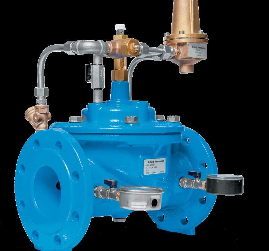
16 6 ERHARD Control Valves Overview of the Variants ERHARD DVP Pressure Reducing Valve This valve is used for converting a fluctuating, higher upstream pressure into a lower, constant downstream pressure. The reduction is independent of fluctuations in flow, a minimum pressure difference of 0.7 bar is required for perfect function. Functional principle of a pressure reducing valve A distinction is made between two different cases for the valve design: If the pressure difference required is less than bar, the flow speed should be between 0. and.5 m/s (case A). If the pressure difference required is greater than bar, the flow speed should be between 0. and 5 m/s (case B). The following values then apply for calculation of the valve size: Case DN A Vmin = 0, m/s Qmin in l/s 0, 0,7,0,6,5 3,5 6,3 Qmin in m 3 /h,5,5 3,6 5,8 9,0,6,7 Vmax =,5 m/s Qmax in l/s,9 8,3 3,0 0,0 3,0,0 79,0 Qmax in m 3 /h 7,6 9,9 6,8 7,0,6 58, 8, B Vmin = 0, m/s Qmin in l/s 0,8,,0 3, 5,0 7,0 3,0 Qmin in m 3 /h 3,0 5,0 7,,6 8,0 5, 6,8 Vmax = 5,0 m/s Qmax in l/s 9,8 7,0 5,0 39,0 6,0 88,0 57,0 Qmax in m 3 /h 35,3 6, 90,0 0, 9,6 36,8 565, Using the nominal size selected as a basis, it can now be checked whether the given data can be covered with the valve without getting into the cavitation area: Upstream pressure (bar) 3 Downstream pressure (bar) Testing the valve s cavitation behaviour: Field : Normal function without cavitation Field : The differential pressure is too high, cavitation occurs. If appropriate, two valves can be arranged behind each other. Field 3: Outside the permissible area of application Field : Physically impossible, since the upstream pressure can never be smaller than the downstream pressure. Example There is an upstream pressure of bar which is to be reduced to a downstream pressure of 6 bar. With the pressure difference of 6 bar, case distinction B is applicable. A maximum flow of 65 l / s and minimum of 8 l / s must be managed, in which case a nominal size DN 50 is selected in case B. A check based on the diagram confirms that the working point is in area and thus no cavitation will occur.
 flows through a fully opened valve at a temperature of 5 to 30 C and a pressure loss of bar.")
17 ERHARD Control Valves 7 The ERHARD DVP pressure reducing valve has favourable KVS and Zeta values. The KVS value specifies how much water (m 3 /h) flows through a fully opened valve at a temperature of 5 to 30 C and a pressure loss of bar. The Zeta value (00 %) is the pressure loss coefficient of the valve in the fully open position. DN KVS (m3/h) Zeta 5,6 6, 6,0 5, 6, 5,0 5,0 Area of application: Water Size DN Pressure rating PN Hydrostatic test pressure in bar Max. allow. gauge working pressure in bar at +60 C ,0-5,0 6, ,0-0,0 5,0 There are numerous options available to supplement the ERHARD DVP pressure reducing valve, e.g. a second pilot valve, solenoids or certain multiple functions. One particularly interesting option is the sustaining of upstream pressure, which closes the valve completely when pressure falls below a certain setpoint upstream pressure. ERHARD DHV Pressure Sustaining Valve The task of a pressure sustaining valve is to avoid increased pressures in pipelines. For one thing, it opens when a set pressure value is exceeded, thus acting as a pressure relief valve and protecting the pipeline from excessively high pressure (diagram A). In addition, it can be used when the upstream pressure is to be kept above a certain limit value, independently of the consumption on the downstream pressure side (diagram B). Application scenarios for the ERHARD DHV pressure sustaining valve A B


18 8 ERHARD Control Valves ERHARD SVP Float Valve The task of float valves is to maintain a certain water level. If the water level in the tank increases, the float slides upwards to the upper stop. The buoyancy of the float lifts the cable with the weight, the counterweight switches the 3/ directional valve so that the upstream line is connected with the control line. The upstream pressure closes the main valve. When the float slides downwards, the process is reversed, the valve remains closed during draw-off from the tank. The main valve only opens once the float has reached the lower stop. The ERHARD SVP float valve thus operates in an adjustable water level height range between 50 and 000 mm as an OPEN-CLOSE valve which is insensitive to cavitation. Closing speed can be set, enabling operation with little water hammer. Sizing is in accordance with the recommended flow quantity. DN l/s 5,0 8,5,5 9,5 3,0,0 78,5 m 3 /h Additional functions such as flow limitation and sustaining the upstream pressure as well as flow speeds of m/s in exceptional cases are possible. Area of application: Water (max. 70 C) Size DN Pressure rating PN on request Installation options for the ERHARD SVP float valve Feeding from above At the outlet of the valve we recommend installing a 90 fitting, the outlet of which ends above the water surface. Feeding from below Feeding from below Float control outside the tank

19 ERHARD Control Valves 9 Application scenario of the ERHARD NRV level regulation valve ERHARD NRV Level Regulation Valve The ERHARD NRV level regulation valve does not use a float to measure the water level, rather this is measured directly by the water pressure in the pilot valve. If the water level and thus the hydrostatic pressure falls, the valve opens wide enough for feed flow and discharge flow to be balanced. This means the ERHARD NRV level regulation valve is not an OPEN-CLOSE valve, but controls the required water quantity flexibly. When a minimum water level is reached, the valve opens completely to achieve fast refilling.
20 0 ERHARD Control Valves Dimensions and weights of the ERHARD control valves with process-medium and pre-control DN L D PN0/6 D PN 5 h h PN 6 h PN 5 e e Weight in kg D L ERHARD DVP Pressure Reducing Valve ERHARD DHV Pressure Sustaining Valve , ERHARD SVP Float Valve , , ERHARD NRV Level Regulation Valve , , , , , , ,8


 coating Area of application: Water (outlet without pressure) Size Pressure Hydrostatic test pressure (bar) Max. allow.")

21 ERHARD Control Valves ERHARD SV Float Valve The tried-and-trusted control valve for level regulation The ERHARD SV float valve is ideal for reliable level control in drinking water supply systems. The high-quality cast iron body has internal fittings made of stainless steel. The float is also made of stainless steel and is connected with the valve via a double float guide and a pressure-balanced piston. The ERHARD SV float valve is available both with at straight pattern and with an angle pattern body with outlet muff or flange. All variants are excellent for stable and economic level control. Brief specifications for materials and equipment Body: Spheroidal graphite cast iron EN-JS 050 Internal fittings and float: Stainless steel Corrosion protection: Internal and external fusion bonded epoxy (FBE) coating Area of application: Water (outlet without pressure) Size Pressure Hydrostatic test pressure (bar) Max. allow. gauge working DN rating PN Body Seat pressure in bar at+60 C ,0,0 0,0 Dimensions and weights DN L H H H3 min H3 max D e d h Hub Kvs Wt. Straight pattern design Angle pattern
22 ERHARD Control Valves Pressure Management and Intelligent Control The task of water supply systems is to keep households and businesses supplied with water at a certain minimum pressure at all times. This also includes the constant supply to critical points such as high buildings or buildings on hills and mountains. The system is thus designed according to the maximum values required for these special points. This means, however, that for the rest of the time such as at night or in months where consumption is low or even zero, the system is over-dimensioned and works with higher pressures than would actually be necessary to supply consumers. Risk of leaks This high pressure leads to problems, however, because the higher the pressure, the greater the risk of leaks, which also result in even greater water loss at higher pressure. In pipes made of rigid materials, the leakage amount increases in line with the square root of the pressure, so that doubling the pressure increases the leakage amount by %, for example. The situation is different where pipes are made of PVC or fibre cement, where even greater damage is done due to the pressure, and the amount increases by up to a factor of eight when the pressure is doubled. Concept and advantages of pressure management The objective, then, is to reduce pressure as far as possible so that the leakage risk is reduced, yet at the same time guaranteeing water supplies at minimum pressure in all areas of the network. This is the task of pressure management, which offers numerous advantages: The overall consumption volumes are lower thanks to reduced leak rates and lower leakage amounts on the one hand, and through the reduced flow at the consumer s due to reduced pressure on the other. Less repair work and an extended service life for pipes and fittings reduces service and maintenance costs. At the same time, customer benefits are increased as less complaints are received about leaks, and there is less strain on fittings and domestic appliances at the consumer s. A: pressure course A (daytime) A: pressure course B (nighttime) Just upstream of PRV Just upstream of PRV 00 Just downstream 0 of PRV 60 At critical point 60 Just downstream of PRV 55 At critical point 0 XX Pressure in m XX Pressure in m

23 ERHARD Control Valves 3 A: Fixed downstream pressure B: Time-controlled modulation C: Flow-controlled modulation Pressure Day Day Day 3 Time Implementation in practice Various methods of different complexities are used to put this concept into practice, all of which can be realised using ERHARD control valves. In the most straightforward case, a pressure reducing valve is used to set the pressure to a fixed value which is sufficient to guarantee the minimum pressure at the critical point at all times (diagram A). No control is required. The pressure reducing valves ERHARD DVF or ERHARD DVP could be used here. This method cannot adapt the pressure to fluctuations in the course of daily and annual usage, but it only involves minimum installation and servicing effort. In contrast, this adaptation is at the heart of the second method, time-controlled modulation (diagram B). Here, the pressure reducing valve is fitted with a timer which adapts the pressure depending on the time and / or season, so that a smoothed pressure curve can be established. A timing device is available both for the ERHARD REV control valve and for the ERHARD DVP pressure reducing valve. Even if this method estimates the draw-off curve on the basis of empirical values and then adapts the pressure accordingly, the actual consumption is not measured. This is done with the third method, flow-controlled modulation. A flow meter is installed upstream from the pressure reducing valve (diagram C). On the basis of this data, the pressure reducing valve is controlled depending on consumption. ERHARD REV control valves and ERHARD DVP pressure reducing valves can be used for this application, too. Finally, the closed measuring loop method carries out measurement at one or several critical points. Here, pressure is measured directly at the draw-off point and the measured value is then transmitted to the pressure reducing valve combined with the flow meter either by data cable or using radio technology, in order to guarantee immediate implementation in the control of the pressure reducing valve. Time control or motorised pilot drives are only some of the options for ERHARD control valves within the context of professional pressure management.


24 Pressure control: constant downstream pressure (P) Y P Flow control: constant flow rate Y R Pressure control: constant upstream pressure (P) W W X X Y Y R 3 3 P P P By-pass valve: for filling mains with the main valve in closes position ERHARD needle valve and control valve Electronic controller* 3 Pressure gauge with teletransmitter Flow meter 5 Float switch 6 Pump W Set point Y Controller output signal X Controller input signal Y R Signal feedback W X Y Y R IDM Q Rserervoir feeding valve 5 MAX MIN Pump-discharge valve: minimizing water hammer on closing a long delivery line 6 Intelligent control Alongside pure pressure management, there are numerous other control tasks to be dealt with in pipeline networks and systems. These include level control in tanks, for example, the control of defined flow volumes or the reduction of water hammer in pump systems (see diagram above). AUMA actuator with integrated PID Controller can be perfectly combined with ERHARD control valves. ERHARD offers numerous options both for the ERHARD REV control valve and for the ERHARD control valves with pilot and process-medium control to guarantee tailor-made adaptation to the respective job on hand. In addition to the standard products (pages 6 to 0), many other models can be configured thanks to additional pilot variants. One particularly interesting option is the integration of control technology directly in the actuator, as can be done with AUMA actuators for the ERHARD REV control valve, for example.


25 ERHARD Control Valves 5 Recommendations for installation Control valves must always be seen as part of an overall installation within the pipeline and be combined with suitable fittings to achieve optimum functionality: The control valve is installed horizontally in the pipeline. On the upstream pressure side, a shut-off valve (e.g. ERHARD Multamed Premium gate valve, ERHARD ROCO Premium butterfly valve or ERHARD ECLI butterfly valve) and a dirt trap with a maximum mesh size of mm must be installed first. On the downstream pressure side, a dismantling joint, a safety valve if appropriate and then another shut-off valve are used. Drainage must be planned in the building. With a downstream pressure line with downward gradient, an air valve (e.g. ERHARD TWIN-AIR air valve) is also recommended on the downstream pressure side, with an upward gradient or horizontal upstream pressure line on the upstream pressure side accordingly.


26 6 ERHARD Control Valves Expertise through tradition It was 87 when the brass caster Johannes Erhard started his business in the small Swabian town of Heidenheim an der Brenz. Since this time, with our valves, we at ERHARD have been helping to ensure that water is available wherever it is needed: in private households, in public facilities, in agriculture or in industrial plant. Proverbial Swabian inventiveness, the most recent technical findings and experience acquired over 0 years ensure that, with innovative solutions and our wide range of products, we can provide suitable systems for every task. Modern machinery, state of the art and environmentally friendly production methods and high-quality materials enable ERHARD to supply technically advanced, fully developed products with worldwide reputation. But merely delivering a product is not enough, especially for complex technical installations. And so at ERHARD, highly qualified teams are available in our head office in Heidenheim and in representations in more than 50 countries to give you advice and support in all the life cycle phases. Planning and design: Individual advice Development of optimum solutions in dialogue In-house laboratory for product tests and trials Installation and commissioning On-site assembly and installation Training and instruction Maintenance and repair Inspections and servicing Fast spare part supply Repairs on site or in our Heidenheim factory including third party makes


![ERHARD ROCO Premium Butterfly Valve [] The soft-sealed butterfly valve with double eccentricity support and optimised flow profile, which has proved its value thousands of times](/docs-images/76/73215362/images/27-3.jpg "over, has been improved even further. Perfect solutions ensure outstanding product properties with respect to operating safety, durability and cost effectiveness.")


![ERHARD TWIN-AIR Air Valve [3] Thanks to its large cross-section and very high venting speeds, this air valve is perfect for use in larger pipelines and guarantees safe and](/docs-images/76/73215362/images/27-6.jpg "automatic venting of the pipe during filling, operational air release in service and emptying. The design is compact and space-saving despite the high capacity.")
27 ERHARD Control Valves 7 ERHARD for every area of application Alongside control valves, the wide ERHARD range also includes numerous other products for pipelines. ERHARD Multamed Premium Gate Valve [] As gate valves of the latest generation, ERHARD Multamed Premium gate valves offer many advantages such as a concealed stem bearing and stem bearing seal with O-rings that can be replaced under full operating pressure if required. An integrated end stop of the stem thread guarantees increased safety, and the innovative dirt cap with integrated sealing lips provides reliable sealing against dust and humidity. The shut-off wedge made of high-grade cast iron with an allround elastomer sheathing guarantees soft sealing and absolute airtightness, a guide profile with integrated sliding blocks for easier actuation. ERHARD ROCO Premium Butterfly Valve [] The soft-sealed butterfly valve with double eccentricity support and optimised flow profile, which has proved its value thousands of times over, has been improved even further. Perfect solutions ensure outstanding product properties with respect to operating safety, durability and cost effectiveness. The innovative polygon plug connection between the shaft and the hub ensures perfect traction. The innovative design also permits complete encapsulation of the shaft-hub connection, so there is no longer any contact between the shaft and the medium. Sealing consistently and logically occurs at coated parts of the component, a decisive plus for protection against corrosion and durability. The slider crank mechanism is optimally matched to the characteristic of the valve, guaranteeing safe actuation. ERHARD TWIN-AIR Air Valve [3] Thanks to its large cross-section and very high venting speeds, this air valve is perfect for use in larger pipelines and guarantees safe and automatic venting of the pipe during filling, operational air release in service and emptying. The design is compact and space-saving despite the high capacity. ERHARD PAS0 Dismantling Joint [] Equipped with three sturdy flange rings, the ERHARD PAS0 is the perfect solution for all standard applications. It is easy to install and remove thanks to the length compensation V =+/- 0 mm or +/- 5 mm (depending on the nominal size) and thus offers perfect support during the installation and removal of fittings. The ERHARD PAS0 has connection flanges with the same dimensions and to both sides, and is lockable. 00 % tension with sturdy, continuous threaded rods guarantees the required safety. 3
28 TALIS is always the number one choice whenever water transport or control is required. TALIS has the best solution for water and energy management, as well as for industry and municipal applications. With a varied range of products we offer comprehensive solutions for the entire water cycle. From hydrants to butterfly valves. From the knife-gate valves to the needle valves. Our experience, innovative technology, global expertise and individual consultation process form the basis for developing sustainable solutions for the efficient handling of the vital resource water. ERHARD GmbH & Co. KG Postfach 80 D-8950 Heidenheim Meeboldstrasse D-895 Heidenheim phone Fax info@erhard.de Internet Note: Specifications may be changed without notification at any time. Copyright: No copying without express written permission of ERHARD ERHARD is a Registered Trademark EN (0/5)
Pressure and Flow Control Valves DBGM, German and European Patents
 Pressure and Flow Control Valves DBGM, German and European Patents Absolutely Reliable Pressure and Flow Control In water mains of sizes DN 50 to DN 150, ERHARD Control Valves in straight or angle pattern
FITTINGS AND VALVES Düker Plunger Valve RKV Type 7015 Professional control of flow rates, reservoir levels and pressures Safe, hygienic and durable!
 FITTINGS AND VALVES Düker Plunger Valve RKV Type 7015 Professional control of flow rates, reservoir levels and pressures Safe, hygienic and durable! 1 The New Düker Plunger Valve Type 7015 St Plunger valves
ERHARD is a company of. ERHARD needle valves
 ERHARD is a company of ERHARD needle valves Needle valves for safe and exact control All the components of the ERHARD RKV needle valves are designed on the basis of decades of experience. At the same time,
Flanged pressure reducer/stabilizer VRCD
 Flanged pressure reducer/stabilizer VRCD 2 This unit reduces and stabilizes the upstream pressure by operating on its load losses with a constant downstream pressure irrespective of the rate of flow value.
BERMAD Waterworks. Level Control Valve with Altitude Pilot. 700 Series. Model X. Features and Benefits. Major Additional Features
 Level Control Valve with Altitude Pilot High level reservoirs & water towers Energy cost critical systems Systems with poor water quality Inherent refreshing Level sustaining at reservoir outlet The Level
Description. Functions. Technical data. Applications. Tests. On-Off 2 levels float control valve, closing at high level and opening at low level.
 DN 0 to 1000 - Serie K3 0 On-Off levels float control valve, closing at high level and opening at low level. Functions Prevents overflowing and closes at a constant and adjustable high level. Remains closed
Ball valve HKSF-W100. Ball valve HKSF-W100. RMA Kehl GmbH & Co. KG Oststrasse 17 D Kehl / Germany
 Ball valve HKSF-W100 RMA Kehl GmbH & Co. KG Oststrasse 17 D-77694 Kehl / Germany info@rma-kehl.de www.rma-armaturen.de 1 Design Features: RMA-ball valves type HKSF-W are fully welded and completely maintenance-free
BACK PRESSURE / SUSTAINING
 In many liquid piping systems, it is vital that line pressure is maintained within relatively narrow limits. This is the function of the 108 Pressure Relief / Back Pressure Series of the OCV control valves.
Paul Ladage 26 September 2017 MOVING THINGS AROUND - LATEST TRENDS IN HONEYWELL FLAGSHIP REGULATORS
 Paul Ladage 26 September 2017 MOVING THINGS AROUND - LATEST TRENDS IN HONEYWELL FLAGSHIP REGULATORS Agenda 1 What do we sell? Flagship Products HON 5020 HON R100 NG HON 512, class 150 Q&A Where Do Honeywell
Bringing Pressure Under Control: Harnessing Control Valves for Intelligent Water Networks. A Report on Best Practice from TALIS
 1 Bringing Pressure Under Control: Harnessing Control Valves for Intelligent Water Networks A Report on Best Practice from TALIS 2 Introduction For a generation focused on smart systems and big data, it
BACK PRESSURE / SUSTAINING
 SPECIFICATIONS DIMENSIONS In many liquid piping systems, it is vital that line pressure is maintained within relatively narrow limits. This is the function of the 108 Pressure Relief / Back Pressure Series
CSO/STORMWATER MANAGEMENT. HYDROVEX FluidMoon Self-Adjusting Knife-Gate Regulator
 CSO/STORMWATER MANAGEMENT HYDROVEX FluidMoon Self-Adjusting Knife-Gate Regulator HYDROVEX FLUIDMOON SELF-ADJUSTING KNIFE-GATE REGULATOR APPLICATION The Hydrovex FluidMoon Self-Adjusting Knife-Gate Regulator
Pressure Reducing Valve DMV 750 set range: bar
 Pressure Reducing Valve DMV 750 set range:.0-6.0 bar Advantage pressure setting possible at any time, also during operation hermetically sealed by valve diaphragm high level of operating safety and long
Mounting and operating instructions EB 2530 EN. Self-operated Pressure Regulator. Pressure Reducing Valve Type M 44-2
 Self-operated Pressure Regulator Pressure Reducing Valve Type M 44-2 Type M 44-2, connection G 1 4, K VS = 0.15 Type M 44-2, connection G 1, K VS = 6 Fig. 1 Type M 44-2 Pressure Reducing Valve Mounting
TECHNICAL DATA. Q = C v P S
 Page 1 of 13 1. DESCRIPTION The Viking 6 Model G-6000 Dry Valve Riser Assembly consists of a small profile, light weight, pilot operated valve that is used to separate the water supply from the dry sprinkler
Series 42 Self-operated Regulators Differential Pressure Regulators with Type 2424/Type 2428 Actuator (closing) Type Type 42-28
 Type Type 42-28") Series 42 Self-operated Regulators Differential Pressure Regulators with Type 2424/Type 2428 Actuator (closing) and balanced Type 2422 Valve Type 42-24 Type 42-28 Application Differential pressure regulators
Series 42 Self-operated Regulators Differential Pressure Regulators with Type 2424/Type 2428 Actuator (closing) and balanced Type 2422 Valve Type 42-24 Type 42-28 Application Differential pressure regulators
DN300 DN2000 C Plunger Valve
 ל DN300 DN2000 C Plunger Valve P.O.B 46 MOSHAV SHTULA WESTERN GALILEE 2286500 Tl. +972-(0)77-6656101, Fax. +972-(0)77-6656196 Website: www.saisanketvalves.com www.saisanket.com email: saisanket@saisanket.com
Pressure relief valve DHV 716 set range: 0,5-10,0 bar
 Pressure relief valve DHV 7 set range: 0,5-0,0 bar Advantage pressure setting possible at any time, also during operation optimum monitoring valves high reproducibility of the set pressure high level of
Mounting and Operating Instructions EB 3017 EN. Self-operated Regulators
 Self-operated Regulars Flow and Differential Pressure Regular Type 42-37 Flow and Differential Pressure or Flow and Pressure Regular Type 42-39 Type 42-37 Type 42-39 Fig. 1 Flow and differential pressure
Pressure Reducing Valve for Steam Type 2333 A
 Pressure Reducing Valve for Steam Type 2333 A Fig. 1 Type 2333 A 1. Design and principle of operation The pressure reducing valve consists of a balanced control valve and a closing actuator equipped with
Serie ECO 3F. Flanged back flow preventer with controllable reduced pressure zone. made in. Application fields. Protection
 Flanged back flow preventer with controllable reduced pressure zone made in Application fields WATER FIRE FIGHTING DRINKING WATER 64 www.brandoni.it The ECO 3F flanged backflow preventers, which have a
BEFORE SALES AFTER SALES
 TALIS FP RANGE TALIS FP RANGE TALIS is a leading global provider of premium valves, hydrants and control solutions for water flow control and Fire Protection Systems With a varied range of products, Talis
CAST IRON VALVES FLOAT VALVE
 CAST IRON VALVES FLOAT VALVE NETAFIM CAST IRON VALVES FLOAT VALVE INLINE 25-400MM ANGLE 50-100MM SPECIFICATIONS Manufactured to ISO 9001 Available Valve sizes INLINE Flanged 50mm to 600mm & Threaded 19mm
Bermad Pressure Reducing. Model: 42T
 Bermad Pressure Reducing Pilot Operated Pressure Control Valve Model: 42T Installation Operation Maintenance Manual (IOM) REV. 27.7.17 Page 1 of 12 Safety First BERMAD believes that the safety of personnel
Overview of types. T5-R B2/R B2 en v Subject to changes 1 / 4. k vs (Sequence 2)
") Technical data sheet R3015-..-..-B2 / R3020-..-..-B2 Characterised control valves, 6-way, with internal threads Two sequences (cooling/heating) With a rotary actuator 90 Water-side switching or modulating
Technical data sheet R3015-..-..-B2 / R3020-..-..-B2 Characterised control valves, 6-way, with internal threads Two sequences (cooling/heating) With a rotary actuator 90 Water-side switching or modulating
Pressure relief valve DHV 712 DN 65-80: 0,5-10 bar, DN : 0,3-4 bar, DN 100: 0,5-6 bar
 Pressure relief valve DHV 7 DN 5-80: 0,5-0 bar, DN 5-00: 0, - bar, DN 00: 0,5 - bar Advantage for high pressure stability reliable reduction of pressure peaks and pulsations pressure setting possible at
Mounting and Operating Instructions EB 3007 EN. Self-operated Pressure Regulators. Differential Pressure Regulators (opening) Type Type 42-25
 Type Type 42-25") Self-operated Pressure Regulators Differential Pressure Regulators (opening) Type 42-20 Type 42-25 Type 42-20 Differential Pressure Regulator Type 42-25 Differential Pressure Regulator Mounting and Operating
Self-operated Pressure Regulators Differential Pressure Regulators (opening) Type 42-20 Type 42-25 Type 42-20 Differential Pressure Regulator Type 42-25 Differential Pressure Regulator Mounting and Operating
Pressure Independent Control Series
 Document No. 155-522 Pressure Independent Control Series Two-Way Cast Iron Flanged Bodies, ANSI 125 and 250 Description Siemens Pressure Independent Control Valves integrate three functions into a single
Installation, Operating and Maintenance Manual Overflow Regulator Type 94/ 94 E
 Installation, Operating and Maintenance Manual Overflow Regulator Type 94/ 94 E Table of content 1. General information on installation, operating and maintenance instructions 1.1 Hazard notices 1.2 Qualified
300 Series. Automatic Hydraulic Control Valves
 Automatic Hydraulic Control Valves AVFI Pty Ltd 54 Enterprise Drive Bundoora Vic 3083 p: 03 8467 0000 f: 03 8467 0099 e: avfi@avfi.com.au w: www.avfi.com.au 300 Series General 300 SERIES Automatic Hydraulic
Differential Pressure Regulator Type Type 45-6 (0.1 to 1 bar, DN 15) Mounting and Operating Instructions EB 3226 EN
 Mounting and Operating Instructions EB 3226 EN") Differential Pressure Regulator Type 45-6 Type 45-6 (0.1 to 1 bar, DN 15) Mounting and Operating Instructions EB 3226 EN Edition March 2008 Contents Contents Page 1 Design and principle of operation...................
Differential Pressure Regulator Type 45-6 Type 45-6 (0.1 to 1 bar, DN 15) Mounting and Operating Instructions EB 3226 EN Edition March 2008 Contents Contents Page 1 Design and principle of operation...................
Rp [ ] Sv min. [ ] C215QP-B 15 1/ C215QP-D 15 1/ C220QP-F 20 3/ [ ]
![Rp [ ] Sv min. [ ] C215QP-B 15 1/ C215QP-D 15 1/ C220QP-F 20 3/ [ ]](/thumbs/75/72185867.jpg "Rp [ ] Sv min. [ ] C215QP-B 15 1/ C215QP-D 15 1/ C220QP-F 20 3/ [ ]") Technical data sheet C2..QP-.. For closed cold and warm water systems For modulating control of airhandling and heating systems on the water side Snap-assembly of the actuator overview DN [ ] Vnom [ l/h]
Technical data sheet C2..QP-.. For closed cold and warm water systems For modulating control of airhandling and heating systems on the water side Snap-assembly of the actuator overview DN [ ] Vnom [ l/h]
High Performance BSP Dial Up Pattern Pressure Reducing Valve
 See our full range online at: www.vip-ltd.co.uk High Performance BSP Dial Up Pattern Pressure Reducing Valve VIP Product Code 31/0103 FUNCTION Pressure reducing valves are devices which, when installed
WW-720. Pressure Reducing Control Valve
 WW-720 Pressure Reducing Control Valve (Size Ranges: 2-4 and 6-14 ) Installation Operation & Maintenance Page 1 of 6 1. DESCRIPTION The Model 720 Pressure Reducing is an automatic control valve (powered
Pressure reducing valves Index
 Index General information page Introduction 506 General introduction 507 for a steam plant 509 Product information BSP thread page Brass 510 ; BSP female thread 511 ; BSP male thread 513 Stainless steel
CVI Valve Line. Exceeds the industry s highest standards for reliability and performance
 CVI Valve Line Exceeds the industry s highest standards for reliability and performance Available in the most standard models with the shortest lead times in the industry Exceptional quality every CVI
WW-720. Pressure Reducing Control Valve
 WW-720 Pressure Reducing Control Valve (Size Ranges: 2-4 and 6-14 ) Installation Operation & Maintenance Page 1 of 6 1. DESCRIPTION The Model 720 Pressure Reducing is an automatic control valve (powered
Differential pressure controller (PN 25) AVP - return and flow mounting, adjustable setting
 AVP - return and flow mounting, adjustable setting") Differential pressure controller (PN 25) AVP - return and flow mounting, adjustable setting Description AVP(-F) is a self-acting differential pressure controller primarily for use in district heating systems.
Differential pressure controller (PN 25) AVP - return and flow mounting, adjustable setting Description AVP(-F) is a self-acting differential pressure controller primarily for use in district heating systems.
TECHNICAL DATA 3 MODEL G-3000 DRY VALVE RISER ASSEMBLY
 Page 1 of 13 1. DESCRIPTION The Viking 3 Model G-3000 Dry Valve Riser Assembly is equipped with a small profile, light weight, pilot operated valve that is used to separate the water supply from the dry
Dimensioning open-close, control and pressure-independent valves. Table of contents. General notes for project planning
 General notes for project planning Dimensioning open-close, control and pressure-independent valves Table of contents Introduction 2 Design and dimensioning General 3 Dimensioning steps Open-close valves
TECHNICAL DATA. Q= Cv S
 Page 1 of 13 1. DESCRIPTION The Viking 4 inch Model G-4000 Dry Valve Riser Assembly consists of a small profile, light weight, pilot operated valve that is used to separate the water supply from the dry
Serie ECO 3T. Threaded end back flow preventer with controllable reduced pressure zone. made in. Application fields. Protection E U R O P E
 Serie ECO T Threaded end back flow preventer with controllable reduced pressure zone BRANDONI made in E U R O P E Application fields WATER FIRE FIGHTING DRINKING WATER 74 www.brandoni.it Serie ECO T The
MANUFACTURING - WATER VALVES - INDUSTRIAL VALVES - PENSTOCKS AND GATES - RADIAL GATES - SPECIAL APPLICATIONS
 MANUFACTURING - WATER VALVES - INDUSTRIAL VALVES - PENSTOCKS AND GATES - RADIAL GATES - SPECIAL APPLICATIONS NEEDLE VALVES DI NICOLA INFINAM s.r.l. Legal seat: Via Mazzini, 11 6600 S. Giovanni Teatino
Components for air preparation and pressure adjustment. OUT port position ( ) connected Rear side. of IN port. Air tank. directly.
 connected Rear side. of IN port. Air tank. directly.") Components preparation and pressure adjustment ABP Overview ABP is a component that enables boosting by s only up to twice primary pressure (.0MPa max.) in combination with using air tank but not using
Components preparation and pressure adjustment ABP Overview ABP is a component that enables boosting by s only up to twice primary pressure (.0MPa max.) in combination with using air tank but not using
Pressure Regulating Valves. Models 44, 77 & 68 PS\ UL. Pressure Relief Valve. Dorot Fire Protection Division. Certification & compliance by design
 Fire Protection Div. Dorot Fire Protection Division Models, & 6 PS\ UL Pressure Relief Valve Certification & compliance by design -PS\UL ANSI FCI - Class VI seat leakage class Fire tested to EN ISO 6-:6
Pressure relief valve DHV 725 set range: 0,2-10,0 bar
 Pressure relief valve DHV 75 set range: 0, - 0,0 bar Advantage pressure setting possible at any time, also during operation optimum monitoring valves high reproducibility of the set pressure high level
SUBMITTAL NOTES PROJECT: Ross Model 50RWR-A Pilot Operated Surge Relief Valve with Hydraulic Anticipation. Size: inch / mm
 SUBMITTAL NOTES PROJECT: Ross Model 50RWR-A Pilot Operated Surge Relief Valve with Hydraulic Anticipation Size: inch / mm Every Ross Valve shall be hydrostatically tested for body integrity and tight seating
Mounting and Operating Instructions EB 3009 EN. Self-operated Regulators. Type RS Check Valve (backflow protection)
") Self-operated Regulators Type 42-10 RS Check Valve (backflow protection) Type 42-10 RS Check Valve (backflow protection) Mounting and Operating Instructions EB 3009 EN Edition December 2015 Definition
Self-operated Regulators Type 42-10 RS Check Valve (backflow protection) Type 42-10 RS Check Valve (backflow protection) Mounting and Operating Instructions EB 3009 EN Edition December 2015 Definition
Type EZH Relief or Backpressure Regulator
 Bulletin 71.4 D103574X012 Type EZH December 2017 Type EZH Relief or Backpressure Regulator P1668 Figure 1. Type EZH Relief Valve or Backpressure Regulator Features Bubble Tight Shutoff A knife-edged metal
2-port seat valves PN25 with externally threaded connections
 4 379 2-port seat valves PN25 with externally threaded connections VVG55.. Valve body bronze CC491K (Rg5) DN 15...25 (½...1 ") kvs 0.25...6.3 m3/h Stroke 5.5 mm Sets of ALG.. with threaded and ALS.. with
Differential pressure and flow controller (PN 16) AVPQ - return mounting, adjustable setting
 AVPQ - return mounting, adjustable setting") Data sheet Differential pressure and flow controller (PN 16) AVPQ - return mounting, adjustable setting Description AVPQ is a self-acting differential pressure and flow controller primarily for use in
Data sheet Differential pressure and flow controller (PN 16) AVPQ - return mounting, adjustable setting Description AVPQ is a self-acting differential pressure and flow controller primarily for use in
6-way characterised control valves DN15 / DN 20 / DN 25
 6-way characterised control valves DN15 / DN 20 / DN 25 Table of contents Introduction 2 Project planning 2 Structure of the 6-way characterised control valves 2 Range of use 2 Characteristic curve 3 Flow
BAYARD is a company of. Hydraulic control valve Hydrobloc system
 BAYARD is a company of Hydraulic control valve Hydrobloc system Hydrobloc control valve 1 - Technical data Range: - DN 50 to 1000 for XGS design. - DN 50 to 800 for XG design. - DN 50 to 300 for XGA design
Two-port valves, male threaded, PN25
 4 379 Two-port valves, male threaded, PN25 VVG55... Two-port valves, externally threaded, PN25 Bronze Rg5 DN15... 25 mm (½"... 1") k vs 0.25... 6.3 m 3 /h Stroke 5.5 mm Suitable for type SQS35... or SQS65...
TECHNICAL DATA Q = C. v P S. 2 Model G-2000 Dry valve. Page 1 of 13
 Page 1 of 13 1. Description The Viking 2 Model G-2000 Dry Valve Riser Assembly consists of a small profile, light weight, pilot operated valve that is used to separate the water supply from the dry sprinkler
safety Shut-Off Valve HON 721
 safety Shut-Off Valve HON 7 product information serving the gas industry worldwide safety shut-off valve HON 7 safety shut-off valve HON 7 Application, Characteristics, Technical Data Application safety
Safety Shut-off Valve SSV
 Safety Shut-off Valve SSV 8200-8300 < Accurate operation < Compact design < Easy maintenance Applications The safety shut-off valve is designed for use in gas distribution, and pressure regulation systems.
WW-730. Pressure Sustaining/Relief Control Valve
 WW-730 Pressure Sustaining/Relief Control Valve Installation Operation & Maintenance Page 1 of 6 1. DESCRIPTION The Model 730 Pressure Relief / Sustaining Valve is an automatic control valve designed to
Pressure independent control valve (PICV) FLOWMATIC
 FLOWMATIC") Pressure independent control valve (PICV) FLOWMATIC 145 series FM 21654 003 01262/19 GB replaces dp 01262/17 GB Function The pressure independent control valve is a device composed of an automatic flow
Pressure independent control valve (PICV) FLOWMATIC 145 series FM 21654 003 01262/19 GB replaces dp 01262/17 GB Function The pressure independent control valve is a device composed of an automatic flow
Mounting and Operating Instructions EB EN. Self-operated Pressure Regulators. Type 2335 Excess Pressure Valve with pilot valve
 Self-operated Pressure Regulators Type 2335 Excess Pressure Valve with pilot valve Type 2335 Excess Pressure Valve Mounting and Operating Instructions EB 2552-2 EN Edition January 2016 Definition of signal
PRESSURE REDUCING VALVE RP45 (EN)
") PRESSURE REDUCING VALVE RP45 (EN) DESCRIPTION The ADCA RP45 series pressure reducing valves are single seat bellows sealed controllers, operating without auxiliary energy, designed for use on steam, compressed
PRESSURE REDUCING VALVE RP45 (EN) DESCRIPTION The ADCA RP45 series pressure reducing valves are single seat bellows sealed controllers, operating without auxiliary energy, designed for use on steam, compressed
BERMAD Waterworks. Pressure Reducing Valve. 700 Series. Model 720. Features and Benefits. Major Additional Features
 Pressure Reducing Valve Flow and leakage reduction Cavitation damage protection Throttling noise reduction Burst protection System maintenance savings The Pressure Reducing Valve is a hydraulically operated,
Differential Pressure Control Valve (DPCV)
") Differential Pressure Control Valve (DPCV) PATENTED Technical Data and Installation Instructions Page 1 V2 The modulating valves ART 241 balance and control the differential pressure (DPCV) automatically
Differential Pressure Control Valve (DPCV) PATENTED Technical Data and Installation Instructions Page 1 V2 The modulating valves ART 241 balance and control the differential pressure (DPCV) automatically
CALEFFI. Ball zone valves. series /03 GB
 all zone valves series cert. n ISO / Function Zone valves are used to automatically shut-off the flow of carrier fluid distributed to a system. Specifically: -In central heating systems, they support the
Water. VAG DUOJET Automatic Air Valve Single-chamber type PN 10/16/25/40 - DN KAT-A 1912
 Water VAG DUOJET Automatic Air Valve Single-chamber type Product characteristics and benefits Resilient seated With flange end acc. to EN 1092-2 Single chamber air valve in compact design Very high discharge
Manual Actuated Boiler Blowdown Valves
 Manual Actuated Boiler Blowdown Valves Installation and Maintenance Instructions 1. Safety information 2. General product information 3. Installation 4. Operation 5. Maintenance 6. Spare parts p.1 1. Safety
Overview of types. Technical data. Safety notes
 Technical data sheet R2..-S.. Open-close ball valves, 2-way, with internal thread For open and closed cold and warm water systems For shut-off functions on the water side and 2-point controls in U and
Sapag Control valve MONOVAR
 MONOVAR MONOVAR is the energy dissipating valve Features MONOVAR DN 2000 (80 ) Extremely simple design (patented) Excellent cavitation characteristics Very accurate flow or pressure control Manual or automatic
RB 4700 Commercial & Industrial Regulator
 RB 4700 Commercial & Industrial Regulator The RB 4700 regulator is designed for use in industrial and distribution applications such as district station and heating plants, and for industrial customers.
Overview of types. Technical data
 Technical data sheet R2..xx-S.. Characterised control valves, 2-way, with internal thread For open and closed cold and warm water systems For modulating water-side control of U and heating systems ir bubble
VALVCHEQ BACKFLOW PREVENTERS FIGURE RP03
 Reduce pressure zone device suitable for high and medium hazard rated applications Flanged end connections FEATURES GENERAL APPLICATION The RP03 provides protection from both backsiphonage and backpressure
BERMAD Waterworks. Level Control Valve. with Bi-Level Vertical Float. 700 Series. Major Additional Features. Features and Benefits.
 Level Control Valve with Bi-Level Vertical Float Reservoir filling Very low supply pressure Low noise generation Energy cost critical systems Systems with poor water quality Reservoir outlet Distribution
T e l N o : F a x N o : E m a i l : a i s h c m c - m e. c o m w w w. c m c - m e.
 MU047: Practical Valve Technology: Selection, Installation, Upgrading, Inspection & Troubleshooting MU047 Rev.002 CMCT COURSE OUTLINE Page 1 of 7 Training Description: This five-day intensive course covers
BERMAD Waterworks. Pressure-Reducing Valve. 700 Series. Model 720. Features and Benefits. Major Additional Features
 Pressure-Reducing Valve Flow and leakage reduction Cavitation damage protection Throttling noise reduction Burst protection System maintenance savings The Pressure-Reducing Valve is a hydraulically-operated,
BSA6T and BSA64T Stainless Steel Bellows Sealed Stop Valves Installation and Maintenance Instructions
 1843950/3 IM-P184-03 ST Issue 3 BSA6T and BSA64T Stainless Steel Bellows Sealed Stop Valves Installation and Maintenance Instructions 1. General safety information 2. General product information 3. Installation
Self-operated Pressure Regulators for special applications
 Self-operated Pressure Regulators for special applications Type 2357-31 Pressure Build-up Regulator with safety function and integrated excess pressure valve Application Pressure regulators for cryogenic
Control Valve with ZK Radial Stage Nozzle ZK 210. Original Installation Instructions English
 Control Valve with ZK Radial Stage Nozzle ZK 210 EN English Original Installation Instructions 810691-00 Contents Important Notes Page Usage for the Intended Purpose... 3 Safety Note... 3 Warning... 4
BERMAD Fire Protection Hydraulic Control Valves
 BERMAD Fire Protection Hydraulic Control Valves Control Solutions with the Power to Protect BERMAD - The Company Since its foundation in 1965, BERMAD has focused its efforts on innovation, quality and
Automatic Balancing Valve Pressure difference controller with integrated flow limiter AB-PM DN
 Data sheet Automatic Balancing Valve Pressure difference controller with integrated flow limiter AB-PM DN 40-100 Description AB-PM is ideal for staged installation and commissioning AB-PM is a combined
The Future of Hydraulic Control in Water-Systems
 The Future of Hydraulic Control in Water-Systems A. Heimann Manager of R&D and of Technical Support & Applications Engineering departments at Dorot Automatic Control Valves Dorot Control Valves, Kibbutz
COMPARING PLUG & SEAT REGULATORS & CONTROL VALVES. Lamar Jones. Equipment Controls Company 4555 South Berkeley Lake Road Norcross, GA 30071
 COMPARING PLUG & SEAT REGULATORS & CONTROL VALVES Lamar Jones Equipment Controls Company 4555 South Berkeley Lake Road Norcross, GA 30071 INTRODUCTION The purpose of this paper will be to compare a plug
Reduce pressure zone device suitable for high and medium hazard rated applications Flanged end connections
 VALVCHEQ Backflow Preventers Reduce pressure zone device suitable for high and medium hazard rated applications Flanged end connections Features General application The RP03 provides protection from both
Type overview. R B2 en-gb subject to changes 1
 Technical data sheet R30..-..-..-B2 Characterised control valve, 6-way, Internal thread Two sequences (cooling/heating) with one 90 rotary actuator Switching or modulating control on the water side of
RR 16 Commercial & Industrial Regulator
 Gas RR 16 Commercial & Industrial Regulator Applications The RR 16 regulator is designed for industrial use: gas supply networks, district stations, industries, heating plants, as well as for all installations
STAP. Differential pressure controller DN
 STAP Differential pressure controller DN 65-100 Pressurisation & Water Quality Balancing & Control Thermostatic Control ENGINEERING ADVANTAGE The flanged STAP is a high-performing differential pressure
Operating Manual FSV, FSÖV, SSVF
 Contents 1. General Remarks... 1 1.1. Marking... 2 1.2. Tightness of the Quick-Closing Valve... 2 1.3. Medium... 2 1.4. Ambient and Medium Temperature... 3 1.5. Vibrations... 3 1.6. Pipe Tensions... 3
AWWA C504 COMPLIANT VALVES FROM 3 THRU 108
 AWWA C504 COMPLIANT VALVES FROM 3 THRU 108 PO Box 411 Berwick PA 18603 800-247-VALV www.crispinvalve.com 500 SERIES: Sizes 3-20 Available The K-Flo 500 Series is a heavy-duty resilient seated butterfly
Size : Connection Ends : Min Temperature : Max Temperature : Materials : Cast iron body
 Size : Connection Ends : Min Temperature : Max Temperature : DN 50 to 200 Flanged ISO PN 10/16 ( ISO PN16 for DN200 ) 0 C + 50 C Max Pressure : 16 Bars Specifications : Tangential type Dry dial Magnetic
Model: 720-UL INSTALLATION OPERATION MAINTENANCE. Bermad Pressure Reducing Valve IOM. Model: FP -720-UL Sizes: 2"-12" BERMAD. Application Engineering
 Bermad Pressure Reducing Valve Model: 720-UL INSTALLATION OPERATION MAINTENANCE Application Engineering BERMAD 1. Safety First BERMAD believes that the safety of personnel working with and around our equipment
Pressure Reducing Valve for steam RP 45
 Pressure Reducing Valve for steam RP 45 DESCRIPTION The RP45 series pressure reducing valves are single seat bellows sealed controllers, operating without auxiliary energy,designed for use on steam, compressed
AVP-F. p setting range (bar) Code No. 003H6200
 Code No. 003H6200") Data sheet Differential pressure controller (PN 16) AVP - return and flow mounting, adjustable setting AVP-F - return mounting, fixed setting Description The controller has a control valve, an actuator
Data sheet Differential pressure controller (PN 16) AVP - return and flow mounting, adjustable setting AVP-F - return mounting, fixed setting Description The controller has a control valve, an actuator
Mounting and Operating Instructions EB 3007 EN. Self-operated Pressure Regulators. Type Type Differential Pressure Regulators (opening)
") Self-operated Pressure Regulators Type 42-20 Type 42-25 Differential Pressure Regulators (opening) Translation of original instructions Type 42-20 Differential Pressure Regulator Type 42-25 Differential
Self-operated Pressure Regulators Type 42-20 Type 42-25 Differential Pressure Regulators (opening) Translation of original instructions Type 42-20 Differential Pressure Regulator Type 42-25 Differential
V5001P. Kombi-Auto Differential Pressure Control Valve. Product specification sheet
 V5001P Kombi-Auto Differential Pressure Control Valve Product specification sheet Content Application...1 Special Features...1 Valve Efficiency...1 Technical Data...2 Construction...2 Materials...2 Method
STAP. Differential pressure controllers DN , ANSI flanges
 STAP Differential pressure controllers DN 65-100, ANSI flanges IMI TA / Differential pressure controllers / STAP STAP The flanged STAP is a high-performing differential pressure controller that keeps the
SYSTEM REGULATING VALVES PRESSURE RELIEF VALVE - SRV BRASS & S/STEEL ADJUSTABLE
 SYSTEM REGULATING VALVES PRESSURE RELIEF VALVE - SRV BRASS & S/STEEL ADJUSTABLE This piston style pressure relief valve with conical shaped needle seat for accurate adjustment is available up to 3 in size.
OIL SUPPLY SYSTEMS ABOVE 45kW OUTPUT 4.1 Oil Supply
 OIL SUPPLY SYSTEMS ABOVE 45kW OUTPUT 4.1 Oil Supply 4.1.1 General The primary function of a system for handling fuel oil is to transfer oil from the storage tank to the oil burner at specified conditions
Pressure reduction controller (PN 16, 25, 40)
") Pressure reduction controller (PN 16, 25, 40) AFD / VFG 2( - for water AFD / VFGS 2 - for steam Description The controller has a control valve, an actuator with one control diaphragm and a spring for pressure
Pressure reduction controller (PN 16, 25, 40) AFD / VFG 2( - for water AFD / VFGS 2 - for steam Description The controller has a control valve, an actuator with one control diaphragm and a spring for pressure
627 Series Pressure Reducing Regulators
 627 Series Pressure Reducing Regulators Introduction The 627 Series direct-operated pressure reducing regulators (Figure 1) are for low and high-pressure systems. These regulators can be used with natural
Type 310A-32A Pressure Reducing Regulator and Type 310A-32A-32A Working Monitor Regulator
 January 2009 Type 310A-32A Pressure Reducing Regulator and Type 310A-32A-32A Working Monitor Regulator Introduction The Type 310A pilot-operated high-pressure regulator (Figure 1) is used where high capacity
2-Port Seat Valves with Flange, PN 16
 4 45 2-Port Seat Valves with Flange, PN 6 VVF45... dular cast iron EN-GJS-400-5 valve body DN 50...50 k vs 9...00 m /h Can be equipped with SKB...- or SKC...- electrohydraulic actuators Use For use in