CORRECTIVE ACTION PLAN (COST PROPOSAL NO. 11)
|
|
|
- John Paul Griffith
- 6 years ago
- Views:
Transcription

1 ADREUSA CORRECTIVE ACTION PLAN (COST PROPOSAL NO. 11) CEDAR BLUFF OIL COMPANY, INC. FORT PAYNE BULK TERMINAL TH STREET SOUTHEAST FORT PAYNE, ALABAMA FACILITY I.D. NO INCIDENT NO. AST PPM PROJECT NO CAP-D DECEMBER 15, 2016 Environmental Science and Engineering


2
3 TABLE OF CONTENTS PAGE CERTIFICATION PAGE...III AST RELEASE FACT SHEET... IV AST SITE CLASSIFICATION SYSTEM CHECKLIST... V 1.0 INTRODUCTION BACKGROUND Site Location Adjacent Properties Site Description Site History Site Conditions Soil COC Concentrations in Soil Groundwater COC Concentrations in Groundwater REMEDIAL APPROACH Excavation and Horizontal Recovery Well Installation Recovery Well Installation Soil Borings Soil Sampling and Field Screening Recovery Well Construction Well Completion and Development Soil Disposal Mobile Enhanced Multiphase Extraction Remediation By Natural Attenuation Anticipated Site Response RNA Monitoring Groundwater Elevation Survey Groundwater Sampling Surface Water Sampling...16
4 TABLE OF CONTENTS(continued) PAGE Sample Preservation and Dispatch Laboratory Analyses REPORTING SITE HEALTH AND SAFETY PROJECT SCHEDULE COST ESTIMATE...18 FIGURES (Appendix A) Figure 1 Site Location Map Figure 2 Site Map Figure 3A Geologic Cross Section A-A Figure 3B Geologic Cross Section B-B Figure 4 COC Concentrations in Soil (BTEX/MTBE) Figure 5 Groundwater Elevation Map (July 15, 216) Figure 6 Dissolved Benzene Isoconcentration Map (July 15, 2016) Figure 7 Dissolved MTBE Isoconcentration Map (July 15, 2016) Figure 8 Dissolved Naphthalene Isoconcentration Map (July 15, 2016) Figure 9 Excavation Areas and Recovery Trench / Well Locations Figure 10 Typical Recovery Trench Layout TABLES (Appendix C) Table 1 Soil Analytical Summary Table 2 Groundwater Elevation Survey Data Table 3 Groundwater Analytical Summary APPENDICES Appendix A Figures Appendix B Soil Boring/Monitoring Well Construction Logs Appendix C Tables Appendix D Subcontractor Specifications and Quotations Appendix E Type II Recovery Well Schematic Appendix F Site Health & Safety Plan Appendix G Cost Proposal No. 12 Exacvation & Recovery Well Installation Appendix H Cost Proposal No. 13 First Quarter MEME Events Appendix I Cost Proposal No. 14 Second Quarter RNA/MEME and Effectiveness Monitoring


5
6 AST RELEASE FACT SHEET GENERAL INFORMATION: SITE NAME: ADDRESS: For Payne Bulk Terminal th Street Southeast, Fort Payne, Alabama FACILITY I.D. NO.: UST INCIDENT NO.: AST RESULTS OF EXPOSURE ASSESSMENT: How many private drinking water wells are located within 1,000 ft. of site? 0 How many public water supply wells are located within 1 mile of the site? 0 Have any drinking water supply wells been impacted by contamination from this { } Yes { X } No release? Is there an imminent threat of contamination to any drinking water wells? { } Yes { X } No Have vapors or contaminated groundwater posed a threat to the public? { } Yes { X } No Are any underground utilities impacted or imminently threatened by the release? { } Yes { X } No Have surface waters been impacted by the release? { } Yes { X } No Is there an imminent threat of contamination to surface waters? { X } Yes { } No What is the type of surrounding population? CONTAMINATION DESCRIPTION: Commercial/Residential Type of contamination at site: {X} Gasoline, { } Diesel, { } Waste Oil, { } Kerosene, { } Other Free product present in wells? { } Yes {X} No Maximum thickness measured: Maximum COC concentrations measured in soil: <0.50 mg/kg benzene (B ) 42.2 mg/kg BTEX (B ) <0.50 mg/kg MTBE (B ) 22 mg/kg naphthalene (B ) Current maximum COC concentrations measured in groundwater: mg/l benzene (MW-5) (7/15/16) mg/l BTEX (MW-5) mg/l MTBE (MW-10) mg/l naphthalene (MW-5) ADEM Form 479 8/02 iv
7 ADEM GROUNDWATER BRANCH AST SITE CLASSIFICATION SYSTEM CHECKLIST Please read all of the following statements and mark either yes or no if the statement applies to your site. If you have conducted a Preliminary or Secondary Investigation, all questions should be answered. Closure site assessment reports may not provide you with all the necessary information, but answer the statements with the knowledge obtained during the closure site assessment. SITE NAME: SITE ADDRESS: Fort Payne Bulk Terminal th Street Southeast, Fort Payne, Alabama FACILITY I.D. NO.: UST INCIDENT NO.: AST OWNER NAME: Cedar Bluff Oil Company, Inc. OWNER ADDRESS: P.O. Box 249, Cedar Bluff, Alabama NAME & ADDRESS OF PERSON COMPLETING THIS FORM: Derek Prince, PPM Consultants, Inc Bankhead Highway, Birmingham, Alabama CLASSIFICATION DESCRIPTION YES NO CLASS A IMMEDIATE THREAT TO HUMAN HEALTH, HUMAN SAFETY OR SENSITIVE ENVIRONMENTAL RECEPTOR A.1 Vapor concentrations at or approaching explosive levels that could cause health effects, are present in a residence or building. A.2 CLASS B B.1 B.2 Vapor concentrations at or approaching explosive levels are present in subsurface utility system(s), but no buildings or residences are impacted. IMMEDIATE THREAT TO HUMAN HEALTH, HUMAN SAFETY OR SENSITIVE ENVIRONMENTAL RECEPTOR An active public water supply well, public water supply line or public surface water intake is impacted or immediately threatened. An active domestic water supply well, domestic water supply line or domestic surface water intake is impacted or immediately threatened. B.3 The release is located within a designated Wellhead Protection Area I. CLASS C IMMEDIATE THREAT TO HUMAN HEALTH, HUMAN SAFETY OR SENSITIVE ENVIRONMENTAL RECEPTOR C.1 Ambient vapor/particulate concentrations exceed concentrations of concern from an acute exposure, or safety viewpoint. C.2 CLASS D D.1 Free product is present on the groundwater, at ground surface, on surface water bodies, in utilities other than water supply lines, or in surface water runoff. SHORT TERM THREAT TO HUMAN HEALTH, SAFETY, OR SENSITIVE ENVIRONMENTAL RECEPTORS There is a potential for explosive levels, or concentrations of vapors that could cause acute effects, to accumulate in a residence or other building. D.2 A non-potable water supply well is impacted or immediately threatened. D.3 Shallow contaminated surface soils are open to public access, and dwellings, parks, playgrounds, day care centers, schools or similar use facilities are within 500 feet of those soils. v
8 ADEM GROUNDWATER BRANCH AST SITE CLASSIFICATION SYSTEM CHECKLIST (continued) CLASSIFICATION DESCRIPTION YES NO CLASS E SHORT TERM THREAT TO HUMAN HEALTH, SAFETY, OR SENSITIVE ENVIRONMENTAL RECEPTORS E.1 A sensitive habitat or sensitive resources (sport fish, economically important species, threatened and endangered species, etc.) are impacted and affected. CLASS F SHORT TERM THREAT TO HUMAN HEALTH, SAFETY, OR SENSITIVE ENVIRONMENTAL RECEPTORS F.1 Groundwater is impacted and a public well is located within 1 mile of the site. F.2 Groundwater is impacted and a domestic well is located within 1,000 feet of the site. F.3 Contaminated soils and/or groundwater are located within designated Wellhead Protection Areas (Areas II or III). CLASS G SHORT TERM THREAT TO HUMAN HEALTH, SAFETY, OR SENSITIVE ENVIRONMENTAL RECEPTORS G.1 Contaminated soils and/or groundwater are located within areas vulnerable to contamination from surface sources. GLASS H SHORT TERM THREAT TO HUMAN HEALTH, SAFETY, OR SENSITIVE ENVIRONMENTAL RECEPTORS H.1 Impacted surface water, stormwater or groundwater discharges within 500 feet of a surface water body used for human drinking water, whole body water-contact sports, or habitat to a protected or listed endangered plant and animal species. CLASS I LONG TERM THREAT TO HUMAN HEALTH, SAFETY, OR SENSITIVE ENVIRONMENTAL RECEPTORS I.1 Site has contaminated soils and/or groundwater but does not meet any of the above mentioned criteria. ADDITIONAL COMMENTS: Little Wills Valley Branch is located approximately 50 feet from the site. There is no current data to indicate that the surface water has been impacted from the release. A spring was located approximately 700 feet northeast of the site in Spring Grove Park. The municipal water is supplied by a surface water intake from the Allen Branch and Big Wills Creek Reservoirs located approximately 6.5 miles north/northeast of the site. Groundwater with COC concentrations above the ISLs is located approximately 10 feet BGS and should be deeper than subsurface utilities in the area. According to the U.S.G.S. Water Well website, there is a water well located approximately 3,700 feet northeast of the site. Complete the classification evaluation questions listed above. Upon completion, determine the highest rank of the site (A.1 is the highest rank) based on the statements answered with a yes. Enter the determined classification ranking: F.1 ADEM GROUNDWATER BRANCH SITE CLASSIFICATION CHECKLIST vi
9 Cedar Bluff Oil Company, Inc. Corrective Action Plan December 15, INTRODUCTION PPM Consultants, Inc. (PPM) was retained by Cedar Bluff Oil Company, Inc. to prepare a Corrective Action Plan (CAP) for the Fort Payne Bulk Terminal located at th Street Southeast, Fort Payne, Alabama. The preparation of the CAP Evaluation was required by the Alabama Department of Environmental Management (ADEM) with their approval of Cost Proposal No. 11 via letter dated September 6, The purpose of this CAP is to provide an approach to decrease constituent of concern (COC) concentrations in groundwater to below Site-Specific Corrective Action Levels (SSCALs). The COCs for the site include benzene, toluene, ethylbenzene, and total xylenes (BTEX), methyl tertiary butyl ether (MTBE), and naphthalene. This CAP provides a summary of pertinent environmental activities conducted to date at the facility and a detailed description of the proposed approach for site remediation. A schedule and cost estimates are included for the implementation of the CAP and associated effectiveness monitoring. 2.0 BACKGROUND 2.1 SITE LOCATION The Fort Payne Bulk Terminal is operated as a retail/commercial gasoline and diesel refueling facility located in a mixed industrial, commercial, and residential area of the city of Fort Payne, Alabama. Geographically the site is located in the northeast ¼ of the northeast ¼ of Section 18, Township 7 South, Range 9 East, on the Fort Payne, Alabama, Quadrangle. More specifically the site is located at North latitude and West longitude. The site location is shown in Figure 1, Site Location Map in Appendix A, Figures. 2.2 ADJACENT PROPERTIES The site is located in a mixed industrial, commercial, and residential area of Fort Payne. Residential properties are primarily located east and southeast of the site. Builders Supply Company is located to the west and northwest of the site adjacent to the north and south side of 8 th Street Southeast. DeKalb Wholesale is located northeast of the site adjacent to 1
10 Cedar Bluff Oil Company, Inc. Corrective Action Plan December 15, th Street Southeast. A vacant commercial building is located southwest of the site and is owned by James and Company, LLC. 2.3 SITE DESCRIPTION The site is located in a relatively flat area of Railroad Valley at the base of Lookout Mountain which is located within 1,500 feet east of the site. The site gradually slopes toward the west toward Little Wills Valley Branch. The Fort Payne Bulk Terminal is operated as a commercial bulk storage facility for Cedar Bluff Oil Company, Inc. The terminal serves the public for the retail purchase of fuels with dispensers available for the purchase of high sulfur (off-road) diesel, taxable road diesel, mineral spirits, and racing fuel. Structures at the site include an office/workshop building, eight bulk above ground storage tanks (ASTs) with an earthen berm for containment, and a loading rack with a canopy for loading commercial vehicles for fuel delivery at other retail facilities. The bulk ASTs are located in a line along the southwestern property line that trends northwest to southeast. The site property is enclosed with an 8-foot chain-link fence with two entrances along the northeastern property line from 8th Street Southeast. A mineral spirits dispenser is located under a canopy north of the AST berm and adjacent to the concrete pad containing the loading rack for off-loading fuel to the bulk AST assembly. An oil-water separator is located in the west corner of the property. A former loading rack is located north of the oil-water separator. A 3,000-gallon AST containing racing fuel and the associated dispenser are located on the north corner of the property. The property is mostly covered by gravel, with the exception of the vicinity of the loading rack, which is covered by concrete and the outer perimeter of the property along the fence is covered with grass. Site features are shown in Figure 2, Site Map. The AST system in ascending order from southeast to northwest consists of the following: two 20,000-gallon ASTs containing regular gasoline; one 20,000-gallon AST containing high sulfur diesel; one 20,000-gallon AST containing E-10 regular gasoline; one 30,000- gallon AST containing high sulfur diesel; one 30,000-gallon AST containing mineral spirits; one 30,000-gallon AST containing taxable road diesel; and one 30,000-gallon AST containing premium unleaded gasoline. 2
11 Cedar Bluff Oil Company, Inc. Corrective Action Plan December 15, 2016 Underground utilities located at the site include storm sewer, sanitary sewer, and water. An underground water line was reported by Cedar Bluff personnel to be present beneath the number 7 or 8 AST and traverses north across the parking lot before trending northwest toward 8th Street Southeast. A water meter was located south of 8th Street Southeast but the water line was not marked on the site property. A 24-inch diameter concrete pipe was located near the northwestern gate adjacent to 8th Street Southeast. The pipe terminates in a ditch that runs parallel to 8th Street Southeast and diverts water to Little Wills Valley Branch. The surface water in the branch flows northeast to southwest along the northwestern property boundary. Two underground electric lines were also reported by onsite personnel that originated from the maintenance building and trend to the west across the site to supply electricity to the dispensers and pumps at the property. The electrical conduits were exposed in several locations but the locations are approximate. The location of the sanitary sewer line is unknown but an approximate 3-inch diameter sewer line was observed in the right-of-way in the ditch along 8th Street Southeast. Subsurface utilities are shown in Figure SITE HISTORY The following provides a brief summary of pertinent events conducted at the site: Emergency Response: Cedar Bluff Oil employees observed gasoline on the loading pad and within the containment dike surrounding the ASTs on November 9, JAT Oil had delivered E-10 unleaded gasoline to the site on November 8, 2012, and failed to close the gate valve at the AST manifold. The check valve for the line did not function properly and gasoline was released to the loading pad surface and drained into the containment dike. Cedar Bluff employees contacted JAT Oil and began pumping the contained fuel from the berm into available tank trucks owned by Cedar Bluff. JAT Oil retained Marion Environmental, Inc. (MEI) to preform emergency response activities. Cedar Bluff Oil and JAT Oil employees estimated from the tank gauge that approximately 1,448 gallons of E- 10 unleaded gasoline had drained from the AST to the loading pad and containment dike. MEI observed free product in the ditch along 8 th Street Southeast, just outside the property boundary. MEI excavated soil from the ditch along 8 th Street Southeast and the area near the oil/water separator located in the downgradient edge of the containment dike. These areas were backfilled with clean soil. In addition to the ditch excavation and pumping product and water from the containment dike, MEI also advanced nine soil borings for field screening purposes on November 13, 2012, in the areas around the release, the oil water separator, and the ditch along 8 th Street Southeast. 3
12 Cedar Bluff Oil Company, Inc. Corrective Action Plan December 15, 2016 Preliminary Investigation: ADEM correspondence dated April 3, 2013, directed Cedar Bluff Oil Company, Inc. to complete a Preliminary Investigation at the site. PPM advanced five soil borings (B-1 through B-5) at the site on May 16, 2013, and May 17, 2013, and installed three Type II monitoring wells (MW-1 through MW-3). The general lithology of the site consisted of a gravelly clay to clay. Adsorbed benzene concentrations exceeded the initial screening levels (ISLs) in borings B-1 and B-2. Adsorbed MTBE concentrations exceeded ISLs in samples collected from borings B-2, B-3, and B-5. During the groundwater monitoring event completed on May 28, 2013, static groundwater levels ranged from feet below top of casing (BTOC) in monitoring well MW-3 to feet BTOC in MW-1. It appeared that the groundwater encountered in these wells represents a perched aquifer within karst topography. The direction of groundwater flow in the perched aquifer was generally to the east across the site. However, the topographic gradient was toward the west and the Little Wills Valley Branch is located west of the monitoring well locations. Groundwater samples exceeded ADEM ISLs in every monitoring well sampled on May 28, 2013, and the groundwater sample collected from boring B-5 on May 17, Dissolved benzene concentrations in groundwater exceeded ISLs in monitoring wells MW-1 through MW-3. Dissolved MTBE concentrations in groundwater exceeded ISLs in monitoring well MW-3 and in a grab sample that was collected from boring B-5. Polynuclear aromatic hydrocarbons (PAHs) were inadvertently not analyzed in the groundwater sample collected from boring B-5 but samples from the monitoring wells were analyzed per Environmental Protection Agency (EPA) Method 8270C-SIM. The dissolved naphthalene concentration reported for the groundwater sample collected from MW-3 was the only detectable PAH that exceeded an ISL. Secondary Investigation: ADEM correspondence dated February 27, 2014, requested that a Secondary Investigation be conducted at the site to delineate horizontal and vertical COC impact in soil and groundwater. Work included advancement of seven soil borings (B-6 through B-12) and the installation of six Type II monitoring wells (MW-4, MW-5, and MW-7 through MW-10) and one Type III monitoring well (MW-6D). Analytical results from the soil samples collected during the Secondary Investigation indicated that adsorbed COC concentrations exceeded ADEM ISLs in samples collected from borings B-7, B-8, and B-12. During the groundwater sampling event, dissolved COC concentrations exceeded ADEM ISLs in samples collected from MW-1, MW-3, MW-5, MW-6D, and MW-10 (off-site well). The dissolved COC concentrations in groundwater were not defined to the north and south of the site. 4
13 Cedar Bluff Oil Company, Inc. Corrective Action Plan December 15, 2016 Additional Secondary Investigation: PPM completed an Additional Secondary Investigation at the site in March Work included advancement of three soil borings (B-13 through B-15) and the installation of three Type II monitoring wells (MW-11 through MW-13). The general lithology encountered in the borings consists of a silty clay or clay with angular chert gravel. Auger refusal was encountered at depths ranging from 12 to 20 feet below ground surface (BGS). During the groundwater monitoring event completed on March 31, 2015, static groundwater levels ranged from 8.04 feet BTOC in monitoring well MW-5 to feet BTOC in MW-1. The direction of groundwater flow was generally to the east from Little Wills Valley Branch and west from the eastern portion of the site. The two different groundwater flow directions appeared to be centralized in a possible trough near monitoring wells MW-1 and MW-2 that extended to the northeast toward MW-7 and southwest toward MW-10. This observation may be the result of a karst feature that underlies the site and may be from a former sinkhole or solution cavity acting as a conduit in this area. Analytical results from the soil samples collected during the Additional Secondary Investigation indicated that adsorbed COC concentrations were below detection limits (BDL) for soil borings B-13 through B-15, and the horizontal extent of COC impact was defined in all directions. During the groundwater sampling event conducted on March 31, 2015, dissolved COC concentrations exceeded ADEM ISLs in samples collected from MW-1 through MW-3, MW-5, MW-6D, and MW-10. The dissolved COC concentrations in groundwater were defined at the site. Groundwater Monitoring: PPM completed a groundwater monitoring event at the site on October 14, Laboratory analytical results indicated dissolved COC concentrations exceeded their respective ISL values in MW-2, MW-3, MW-5, MW-6D, MW-9, and MW-10. ARBCA Evaluation: PPM completed a Tier 1/Tier 2 Alabama Risk-Based Corrective Action (ARBCA) Evaluation for the site and submitted the document to ADEM on January 27, The objective of the ARBCA Evaluation was to establish SSCALs for COC concentrations in soil and groundwater. ADEM approved the proposed SSCALs in correspondence dated February 3, Corrective Action Plan Evaluation: In correspondence dated February 3, 2016, ADEM requested a cost proposal to conduct a CAP Evaluation. Cost Proposal No. 10 for the CAP 5
14 Cedar Bluff Oil Company, Inc. Corrective Action Plan December 15, 2016 Evaluation was authorized by ADEM on February 29, In the CAP evaluation dated June 16, 2016, PPM recommended excavation of shallow trenches and the installation of horizontal and vertical recovery wells for potential MEME events at the site. In correspondence dated July 14, 2016, ADEM requested a CAP and requested additional monitoring wells to be installed between MW-5 and MW-10. Groundwater Monitoring: PPM completed groundwater monitoring events at the site on February 2, 2016; May 16, 2016; and July 15, Laboratory analytical results indicated the dissolved benzene concentrations exceeded the SSCAL in MW-5 during each of the events. 2.5 SITE CONDITIONS Soil Subsurface lithology was identified from visual inspection of soils encountered during installation of soil borings. Limestone gravel fill was generally encountered from 6 inches to 2 feet BGS. The general lithology of the upper 5 to 15 feet of soil at the site consists of a gravelly clay or clay with chert gravel. The chert gravel was angular and well graded. A clay or silty clay was generally encountered beneath the gravelly clay but chert gravel was observed in most borings near the bedrock contact or (auger refusal). Auger refusal ranged from approximately 12 feet BGS to 29 feet BGS. Representative cross-sections of the lithology encountered at the site are presented in Figure 3A, Cross-Section A-A and Figure 3B, Cross-Section B-B. Soil borings and monitoring well construction logs from previous site investigations are provided in Appendix B, Soil Boring/Monitoring Well Construction Logs COC Concentrations in Soil Based on information obtained during assessments conducted at the site, COC concentrations in soil are below the SSCALs in all soil samples collected from the borings. Soil borings B-1, B-2, B-5, B-6, B-7, B-8, and B-12 contained detectable BTEX concentrations. The highest soil impact was present in boring B-2 from a depth of 2 to 4 feet. Detected COC concentrations in soil were also present in boring B-1 at a depth of 8 to 10 feet BGS and boring B-7 at a depth of 9-11 feet BGS. COC concentrations in soil samples collected from the same borings from depths of 12 to 16 feet BGS were below detection level (BDL). Detectable COC concentrations were also present in the soil 6
15 Cedar Bluff Oil Company, Inc. Corrective Action Plan December 15, 2016 sample collected from a depth of 14 to 16 feet in the off-site boring B-12. Furthermore, detectable naphthalene concentrations were present in soil samples collected from borings B-2 through B-8, B-11, and B-12. However, none of these naphthalene concentrations exceeded a SSCAL. Summaries of analytical data from soil samples collected at the site are presented in Table 1, Soil Analytical Summary Appendix C, Tables. The soil analytical data are also presented on Figure 4, COC Concentrations in Soil (BTEX and MTBE) Groundwater An initial zone of saturation was not typically observed during the advancement of the borings, since they were sampled at 5-foot intervals, but was normally observed once auger refusal was encountered. Although initial saturation was not encountered in all of the borings, it appears that the static groundwater elevations are located in areas of chert gravel or clay with some chert and the intervals were encountered at different depths across the site. Therefore, it appears that the chert intervals act as conduits and may be hydraulically connected to the karst topography at the site. During the July 15, 2016, groundwater sampling event, depth to groundwater measured in each Type II monitoring well ranged from 7.93 feet BTOC in MW-11 to feet BTOC in MW-1. The direction of groundwater flow was generally to the northeast. As a result of the karst topography located at the site, a groundwater elevation depression extends from monitoring well MW-10 northeast toward MW-7. Groundwater elevations measured at the site are shown in Table 2, Groundwater Elevation Survey Data and in Figure 5, Groundwater Elevation Map (July 15, 2016) COC Concentrations in Groundwater During the July 15, 2016, sampling event, groundwater samples were collected from monitoring wells MW-1 through MW-5, MW-6D, and MW-7 through MW-13. The dissolved benzene concentration in groundwater in MW-5 (1.140 mg/l) exceeded the SSCAL ( mg/l). No other COC concentration exceeded a SSCAL. Groundwater analytical results are summarized in Table 3, Groundwater Analytical Summary. The COC impact at MW-5 appears to be the result of the petroleum product that was observed entering the ditch at the discharge end of the stormwater drain during the 7
16 Cedar Bluff Oil Company, Inc. Corrective Action Plan December 15, 2016 emergency response completed by Marion Environmental in The apparent horizontal extent of on-site dissolved COC impact is shown in the following figures: Figure 6, Dissolved Benzene Isoconcentration Map (July 15, 2016) Figure 7, Dissolved MTBE Isoconcentration Map (July 15, 2016) Figure 8, Dissolved Naphtalene Isoconcentration Map (July 15, 2016). 3.0 REMEDIAL APPROACH Based on the data included in the Corrective Action Evaluation, PPM recommends the excavation of shallow trenches and the installation of horizontal and vertical recovery wells for completing mobile enhanced multi-phase extraction (MEME) events at the site. After sufficient COC reduction has occurred, the site can transition to a remediation via natural attenuation (RNA) approach to address residual COC concentrations that may be at or near SSCALs but do not warrant continued efforts from further MEME events. These corrective actions are intended to reduce COC concentrations in groundwater to below SSCALs in a safe, timely, and cost-effective manner. This remedial approach has been selected based on existing site data. Based on the findings of the excavations and recovery wells (horizontal and vertical) proposed in this CAP and subsequent effectiveness monitoring events, a CAP modification may be required in the future. The following provides a description of the excavation and RNA/MEME approach. 3.1 EXCAVATION AND HORIZONTAL RECOVERY WELL INSTALLATION Due to the presence of dissolved COC concentrations at MW-5, believed to be originating from the piping that that traverses from inside the AST containment basin to the open ditch, it appears the pipe served as a direct migratory pathway for the November 2012 release. The piping is reportedly comprised of steel as it exits the basin and at some point transitions to a 24-inch diameter concrete pipe before discharging to the open ditch along 8 th Street Southeast. As such, PPM recommends removing impacted soil from the subsurface via excavations along the traverse of the concrete pipe. The proposed excavations are located in a grass and gravel covered along the northern portion of the property and work should not significantly impede daily activities at the facility. 8
17 Cedar Bluff Oil Company, Inc. Corrective Action Plan December 15, 2016 Each excavation will be extended to a select depth to facilitate construction of a horizontal recovery well. These horizontal recovery wells will aid in removal of dissolved COC impact during proposed MEME events. Three excavations/trenches are proposed at strategic areas along the traverse of the concrete pipe, with emphasis on the area near and up gradient of MW-5. It is anticipated that each trench will extend approximately 12 to 15 feet in length and up to 6 feet in width. Other locations along the piping will also be checked once the approximate locations of the joints are determined. If free product or significantly impacted soils are observed, the excavation may be extended if possible without undermining or damaging the concrete pipe. For the purpose of this CAP, it is assumed that some over excavation will occur at each location; along the traverse of the concrete pipe and at shallow depths (presumed to be less than 6 feet in most areas). Excavated soils will be placed in a stockpile on site underlain and covered with plastic sheeting, pending off-site disposal at an ADEM approved landfill. Three horizontal recovery wells will be constructed at strategic locations along the concrete piping. As the depth to groundwater at MW-5 generally fluctuates from approximately 8 to 10 feet BGS, the total depth of each trench section containing recovery piping will be approximately 10.5 feet BGS. An approximate 6-inch thick layer of gravel (No. 57 stone) will be placed at the bottom of each trench. The recovery well will be comprised of a 10-foot length of 4-inch I.D. polyvinyl chloride (PVC) well screen, an elbow, and an approximate 10-foot length of vertical riser. Gravel will extend from the base of the recovery trenches to a depth of approximately 2 to 3 feet BGS. The top of the trench will be completed with an approximate 1.5 to 2.5-foot thick clay cap above the gravel and an additional 0.5-foot thick layer of crusher run gravel will be placed at the surface. A 2-foot by 2-foot well pad and manhole cover will be constructed at the top of each riser pipe. The locations of the trench excavations are included on Figure 9, Excavation and Recovery Trench/Well Locations. It is noted that the location of the recovery trenches may vary based on observations noted during the excavations. A cross-sectional view of a recovery trench and a proposed horizontal recovery well are shown on Figure 10, Typical Recovery Trench Layout. Technical Drilling Services and Environmental, Inc. provided quotes for the recovery well installation, system demolition, and system installation. Technical Drilling Services was the lowest bid for the excavation and recovery well installation and Environmental, Inc. 9
18 Cedar Bluff Oil Company, Inc. Corrective Action Plan December 15, 2016 was the lower total bid for the soil disposal. The quotations are provided in Appendix D, Subcontractor Specifications and Quotation. 3.2 RECOVERY WELL INSTALLATION Per ADEM request to install additional delineation wells between MW-5 and MW-10, PPM recommends installing two vertical recovery wells along either side of the discharge pipe in the area located between the November 2012 release and the current COC impact present at MW-5. The proposed 4-inch I.D. recovery wells (PRW-1 and PRW-2) will be installed to depths of approximately 18 feet BGS in the areas shown on Figure 9. This total depth is based on prior data obtained in the general area Soil Borings Prior to advancing borings and excavating soils, Southern Radar Imaging will conduct a private line locate of the work area using ground penetrating radar (GPR). The GPR survey will aid in identifying the presence of subsurface utilities and the location of the steel/concrete piping from the AST basin to the drainage ditch. A copy of the quote provided by Southern Radar Imaging is included in Appendix D. The first 4 feet of each soil boring will also be advanced with hand-held equipment to check for the presence of unmarked utilities. The hand-held equipment will be cleaned prior to use at each boring location by means of a phosphate free soap rinse, an isopropyl alcohol rinse, and a rinse of distilled water. Rinse fluids will not be contained but allowed to fall to the land surface in an area that provides drainage away from the respective boring location. The borings for the proposed recovery wells will then be advanced to a depth of approximately 18 feet BGS. The borings will be advanced with 6.25-inch I.D. continuous flight, hollow-stem augers for installation of 4-inch I.D. recovery wells. Soil cutting generated during boring advancement will be placed in a stockpile on site underlain and covered with plastic sheeting, pending off-site disposal at an ADEM approved landfill. 10
19 Cedar Bluff Oil Company, Inc. Corrective Action Plan December 15, Soil Sampling and Field Screening Soil samples will be collected continuously to aid in the correct placement of the screened interval of the recovery wells. However, only two soil samples will be submitted to a laboratory for analysis per boring. Soil samples will be visually described in general accordance with the Unified Soil Classification System (USCS). A portion of each soil sample will be placed in a mason jar for field screening purposes. Soil samples will be analyzed for BTEX, MTBE, and naphthalene per EPA Method Field screening of soil samples will be conducted using headspace analyses techniques with a portable combustible gas detector (RKI Eagle). Headspace analyses will consist of half-filling glass jars with soil and covering the jars with aluminum foil. The probe tip of the instrument will be inserted through the aluminum foil to obtain a headspace reading once vapors inside the jar have been allowed time to equilibrate. The combustible gas detector will be calibrated prior to use in general accordance with the manufacturer s specifications. PPM personnel will wear disposable nitrile gloves during sample collection in an effort to reduce the potential for cross-contamination and as part of personal protective equipment (PPE) for the project. Gloves will be changed and discarded between each sample acquisition Recovery Well Construction The two vertical recovery wells will be constructed with 4-inch I.D., Schedule 40 PVC with 10 to 15-foot sections of 0.01-inch slotted screen and a PVC riser to complete the well to just below the ground surface. Sand will be placed in the boring annulus for each of the recovery wells from the bottom of the boring to approximately 2 feet above the screen. A bentonite seal approximately 2 feet thick will be constructed above the sand pack, and the remaining annular space will be grouted to the bottom of the manhole cover. Recovery wells will be completed with 12-inch I.D. steel manhole covers that extend slightly above the existing land surface in an effort to reduce the potential for surficial contamination. Each recovery well will be subsequently surveyed by PPM for horizontal and vertical control. Locations will be referenced to existing monitoring wells at the site. A general description of the well details is shown in Appendix E, Type II Recovery Well Schematics. 11
20 Cedar Bluff Oil Company, Inc. Corrective Action Plan December 15, Well Completion and Development Newly installed recovery wells will be developed by pumping or manual bailing until the discharged water is relatively clear and free of sediments or until the well is dry. The development water will be contained in 55-gallon drums and removed during a subsequent MEME event. The MEME contractor will transport the water to Allied Energy Corporation of Birmingham, Alabama. PPM estimates approximately 165 gallons of development water will require disposal. 3.3 SOIL DISPOSAL The soil generated during the trenching and well installation activities will be placed in a stockpile (underlain and covered by plastic) pending approval of a Solid Waste Certification. ADEM will require laboratory analyses of the soil stockpile and profile fee. PPM will collect approximately one composite soil sample, as an estimated 100 cubic yards of soil may be generated (excavation and soil cuttings). The composite soil sample collected from the soil stockpile will be analyzed for benzene per EPA Method 8260 and total lead per EPA Method Upon ADEM approval, Environmental, Inc. will transport the soil to the Advanced Disposal Star Ridge Landfill in Moody, Alabama for disposal. 3.4 MOBILE ENHANCED MULTIPHASE EXTRACTION MEME events will be conducted to reduce dissolved COC impact in an effort to facilitate more rapid attenuation of COC in groundwater. Two 8-hour MEME events will be performed following each quarterly groundwater sampling event. The MEME events will be completed during the second and third months of each quarter. This will result in a total of eight MEME events over the course of the first year of RNA/MEME effectiveness monitoring. MEME is a remedial technique that utilizes high vacuum pressures and flow rates to extract vapor and liquid from the subsurface via recovery/monitoring wells by means of a truck or trailer-mounted mobile vacuum unit. Recovered fluids are temporarily contained in holding tanks on site and subsequently transported off site for proper disposal. The use of high vacuum/airflows can result in higher fluid recovery rates in comparison to traditional pump and treat methods. MEME also aids in removing COCs adsorbed to the soil matrix. 12
21 Cedar Bluff Oil Company, Inc. Corrective Action Plan December 15, 2016 Vacuum gauges and flow gauges are connected to the extraction wells to record the removal rate from each well. Influent and effluent flow rates and vapor concentrations are measured at the thermal oxidizer to estimate the mass of hydrocarbons recovered and treated prior to discharge to the atmosphere. Recovered liquids are transported off site to a permitted facility for disposal or recycling A representative of PPM will be on site during each event, which will be performed by Fruits & Associates, Inc. (Fruits) of Acworth, Georgia utilizing a mobile vacuum truck. A thermal oxidizer will be used to treat off-gases prior to release to the atmosphere. The ADEM Air Division will be notified prior to initiating MEME events at the site. Groundwater levels will be measured at select monitoring wells prior to initiating each MEME event to establish static conditions for comparison to conditions observed during the event. Vacuum gauges will be installed in the flexible 2-inch hoses that connect the wellheads to the vacuum pump. A gate valve will control the applied vacuum to each extraction point. Airflow rates, volatile organic compound (VOC) concentrations, and applied vacuum will be measured periodically throughout the event. Field measurements will be used to evaluate the site response to treatment and estimate the pounds of hydrocarbons removed throughout the operating period. PPM recommends that the three proposed horizontal recovery wells (PHW-1 through PHW-3) and two proposed vertical recovery wells (PRW-1 and PRW-2) be utilized as extraction points during proposed MEME events. During the initial events, vacuum will be applied to each location for a minimum of 2 hours over the course of an 8-hour event. Based on the observed hydrocarbon recovery rates during these initial events, modifications will be made during future events to enhance hydrocarbon recovery rates over the 8-hour period. This will result in more recovery time for areas that produce elevated hydrocarbon removal. In addition, the duration/frequency of the MEME events can be modified with ADEM approval, based on results of subsequent groundwater monitoring activities. 3.5 REMEDIATION BY NATURAL ATTENUATION Natural attenuation is a term applied to the processes that help reduce contaminant concentrations and, in some cases, reduce the potential for contaminant migration. There are multiple components that comprise natural attenuation including: biodegradation; sorption; dispersion and dilution; and volatilization. Biodegradation is often considered 13
22 Cedar Bluff Oil Company, Inc. Corrective Action Plan December 15, 2016 the most important component of RNA as it results in chemical changes to the contaminant often rendering it less harmful to the environment. RNA is typically not considered for sites with elevated contaminant concentrations or free product, as it will generally not achieve site objectives within a reasonable time frame. However, RNA is often selected for sites with low to moderate impact that show indications that it may be effective. In addition, RNA may be used in conjunction with other remedial methods that address contaminant source control Anticipated Site Response Based on prior analytical data that generally indicate stable to decreasing dissolved COC concentrations at MW-5, it is anticipated that site conditions will continue to improve with respect to overall groundwater quality. There are multiple secondary approaches for monitoring RNA effectiveness including estimating a first order rate of attenuation and measuring select water quality parameters. Both methods may be employed to evaluate the overall effectiveness of RNA at the site. However, the stable and/or decreasing trends of dissolved COC concentrations will be the primary gauge of RNA effectiveness. A first order rate of attenuation constant can be estimated for select wells in general accordance with the U.S. EPA publication entitled Calculation and Use of First-Order Rate Constants for Monitored Natural Attenuation Studies (November 2002). The following formula may be used to estimate the approximate time frame required to achieve SSCALs through use of natural attenuation: t = Ln C Kpo int Cgoal start Where: t = time, yrs C goal = desired COC concentration, mg/l C start = initial COC concentration, mg/l k point = time rate constant Select water quality parameters [ph, temperature, conductivity, oxidation reduction potential (ORP), dissolved oxygen, etc.] will also be monitored during the RNA 14
23 Cedar Bluff Oil Company, Inc. Corrective Action Plan December 15, 2016 groundwater monitoring events. However, sampling for other RNA parameters (nitrate/nitrite, manganese, iron, sulfate, and methane) is not recommended at this time RNA Monitoring To monitor the effectiveness of the MEME/RNA approach, PPM recommends that quarterly groundwater monitoring events be conducted at the site for a period of at least one year. The scope of work for each event will generally consist of the following activities: PPM recommends that all monitoring wells and vertical recovery wells be sampled during implementation of corrective actions to establish baseline conditions prior to initiating MEME events at the site. In addition, all monitoring wells and vertical recovery wells should be sampled during the second through fourth quarters of the first year. PPM anticipates that limited groundwater sampling can be conducted during three of the four quarters completed during the second year of corrective actions, if needed. Field activities will be conducted in general accordance with PPM s Quality Assurance/Quality Control (QA/QC) Plan for groundwater sampling consistent with EPA/ADEM protocol. No deviation from the proposed scope of work will be made without approval from ADEM. The following provides a detailed description of the investigative methodology to be employed during the completion of the proposed scope of work Groundwater Elevation Survey Site depth to groundwater and groundwater flow direction will be estimated through a quarterly groundwater elevation survey competed prior to each groundwater sampling event. Depth to groundwater measurements will be accomplished with an oil/water interface probe capable of measuring the water depth to within +/ feet. The interface probe will be cleaned prior to use at each well location by means of a phosphate free soap rinse, an isopropyl rinse, and a rinse of distilled water. Rinse fluids will be discharged to the land surface in areas that do not drain back to the respective well locations. Groundwater depths will be measured in each accessible well from a point on the north side of the top of casing using the interface probe. The well casing elevations and groundwater depths will be used to calculate groundwater elevations and flow direction. In 15
24 Cedar Bluff Oil Company, Inc. Corrective Action Plan December 15, 2016 addition, groundwater depths will be used to calculate well-casing volumes prior to well purging activities Groundwater Sampling Following the installation of the two proposed recovery wells, PPM will complete a comprehensive baseline groundwater sampling event to include 13 monitoring wells and the two proposed recovery wells. Additional groundwater monitoring events will be conducted once per quarter during the first month of each quarter. This will allow the purge water to be removed each quarter during the subsequent MEME event. Monitoring wells will be sampled in general accordance with PPM s internal QA/QC Plan for sampling at UST sites. Prior to sampling, each well will be purged of approximately three well-casing volumes (or to near dryness) in an effort to obtain samples representative of subsurface conditions. Single use, disposable PVC bailers and nylon rope will be used to purge each well and to facilitate sample collection. During the groundwater sampling events, purge water removed from the wells will be temporarily contained on site in 55-gallon drums. The purge water contained in the drums will be removed during a subsequent MEME event. Each sample will be transferred from the bailer into 40-milliliter (ml) glass vials containing hydrochloric acid (HCl) as a preservative. Each container will be filled with the sample, promptly capped, and appropriately labeled to indicate the sample origin. Containers will be subsequently placed in an iced cooler for preservation during shipment to the laboratory. A duplicate sample will be collected from one monitoring well in accordance with QA/QC protocol. Disposable nitrile gloves will be worn during each well purge and sample collection in an effort to reduce the potential for cross-contamination. Gloves will be changed and discarded between each sample acquisition Surface Water Sampling PPM will collect three surface water samples from Little Wills Valley Branch located west of the site. The surface water samples will be collected from the most downstream location first and progress in an upstream direction. Surface water sampling locations are shown in Figure 2. 16
25 Cedar Bluff Oil Company, Inc. Corrective Action Plan December 15, Sample Preservation and Dispatch Each sample retained for laboratory analyses will be promptly placed on ice and preserved at approximately 4 degrees Celsius ( o C). The samples will be labeled to document the appropriate project information. Samples will be sealed within insulated coolers and transported under chain-of-custody protocol to an independent laboratory for analysis Laboratory Analyses Groundwater samples will be analyzed for BTEX, MTBE, and naphthalene per EPA Method REPORTING PPM will submit an Excavation and Recovery Well Installation Report within approximately 60 days following completion of the field activities. The report will present the findings and conclusions regarding COC impact in soil (proposed recovery wells) and groundwater (all monitoring wells and vertical recovery wells). The report will be prepared by or under the guidance of an Alabama-registered professional engineer or geologist experienced in conducting subsurface environmental investigations. Future quarterly RNA/MEME effectiveness monitoring reports will be prepared and submitted within approximately 45 days of the second MEME event each quarter. Reports will include a detailed description of the field work performed and a summary of the associated findings. It is noted that the first report submitted after the Excavation and Recovery Well Installation Report will address only the two proposed MEME events to be conducted after the initial baseline sampling effort. Additional effectiveness monitoring reports will include a summary of the groundwater sampling results (first month of the quarter) and the two subsequent MEME events (second and third months of the quarter). Current and historical groundwater elevation and analytical data will be presented in summary tables. In addition, figures will be provided indicating the apparent direction of groundwater flow and estimated extent of COC impact. The reports will be reviewed by an engineer or geologist experienced in conducting subsurface environmental investigations and corrective actions. A copy of the MEME contractor s reports will be included. 17
26 5.0 SITE HEALTH AND SAFETY Cedar Bluff Oil Company, Inc. Corrective Action Plan December 15, 2016 A site-specific Health and Safety Plan (HASP) for proposed corrective action activities at the facility is included in Appendix F, Site Health and Safety Plan. The HASP was specifically designed to address the proposed activities at the site. All project personnel will be familiar with the HASP, and the HASP will be kept on site throughout the duration of the MEME events. 6.0 PROJECT SCHEDULE It is estimated that a report can be submitted within 90 days of ADEM authorization. The following provides the anticipated schedule for completion of the proposed scope of work. TASK TOTAL DAYS Date of ADEM authorization Day 0 PPM receipt of authorization Day 5 Drilling/Excavation (based on subcontractor availability) Day 40 Well development Day 45 Collection of groundwater samples/survey Day 50 Soil Disposal Day 65 Submittal of report to Agency/Client Day 90 ADEM receipt of report Day 92 PPM proposes to conduct RNA effectiveness monitoring on a quarterly basis for at least one year or until COC concentrations at the facility remain at or below SSCALs for two consecutive quarterly periods. If at any time during these activities it is deemed necessary to perform additional efforts, PPM will contact ADEM to discuss and subsequently submit an addendum request to perform the additional work. 7.0 COST ESTIMATE The work elements for CAP implementation are eligible for reimbursement from the Alabama Tank Trust Fund (ATTF). Cost proposals for implementation of the CAP are included as follows. 18
27 Cedar Bluff Oil Company, Inc. Corrective Action Plan December 15, 2016 Appendix G Cost Proposal No. 12 Excavation and Recovery Well Installation Appendix H Cost Proposal No. 13 First Quarter RNA/MEME Appendix I Cost Proposal No. 14 Second Quarter RNA/MEME - Effectiveness Monitoring. 19
28 APPENDICES
29 APPENDIX A FIGURES

30 Z:\Cedar Bluff Oil Company Inc\424701\Cap-D\ Cap-D.dwg, 1 slm, 12/14/ :41:18 AM, brian hicks SITE LOCATION FORT PAYNE QUADRANGLE-1982 SCALE: 1 : 24, MILES 1000 PPM PPM CONSULTANTS, INC. DRAWN BY: BWH PROJECT NUMBER: DRAWN DATE: 10/17/16 BILLING GROUP: CAP-D 5000 FEET KILOMETER METER CEDAR BLUFF OIL COMPANY, INC. 10, FORT PAYNE BULK TERMINAL 320 8TH STREET SOUTHEAST FORT PAYNE, ALABAMA FIGURE NUMBER SITE LOCATION MAP 1
31 COMMERCIAL TANK I.D. SERVICE 1 UNLEADED REGULAR 2 UNLEADED REGULAR N B-15/ MW-13 3 HIGH SULFUR DIESEL 4 E-10 5 HIGH SULFUR DIESEL 6 MINERAL SPIRITS SW-1 W WATER METER 7 TAXABLE ROAD DIESEL 8 PREMIUM UNLEADED SCALE: 1"=40' (Approximate) RACING FUEL AST B-7/ MW-5 Z:\Cedar Bluff Oil Company Inc\424701\Cap-D\ Cap-D.dwg, 2 sm, 12/14/ :41:19 AM, brian hicks SW-3 PPM DRAWN BY: BWH PROJECT NUMBER: COMMERCIAL P P M C O N S U L T A N T S, I N C. DRAWN DATE: FLOW NOTE: LOCATIONS OF ALL UTILITIES ARE APPROXIMATE. 10/17/16 BILLING GROUP: CAP-D SW-2 LITTLE WILLS VALLEY BRANCH OIL / WATER SEPARATOR B-11/ MW-9 B-13/ MW-11 G PROPERTY BOUNDARY B-12/ MW-10 WATER SPIGOT FORMER GAS METER LOADING RACK B-4/ MW-3 B-8/ MW-6D DIESEL DISPENSER B-10/ MW-8 8 B-5 GRAVEL 7 B-14/ MW-12 OFF-ROAD DIESEL DISPENSER EARTHEN CONTAINMENT DIKE B-2/ MW-2 B-1/ MW-1 CEDAR BLUFF OIL COMPANY, INC. FORT PAYNE BULK TERMINAL 320 8TH STREET SOUTHEAST FORT PAYNE, ALABAMA 6 B-3 PAD CONCRETE 5 VACANT MINERAL SPIRITS DISPENSER 4 3 RACING FUEL DISPENSER LOCATION OF SURFACE RELEASE 2 24" CONCRETE DRAINAGE PIPE 1 CANOPY LOADING RACK B-6/ MW-4 GRAVEL BAY DOORS GRAVEL B-9/ MW-7 8TH STREET SOUTHEAST SHOP OFFICE PROPANE TANK SITE MAP 1 LEGEND: SOIL BORING LOCATION DRAINAGE DITCH TANK I.D. WOODED AREA SOIL BORING / TYPE II MONITORING WELL LOCATION SOIL BORING / TYPE III MONITORING WELL LOCATION SURFACE WATER SAMPLE LOCATION (APPROXIMATE) FENCE UNDERGROUND POWER LINE WATER LINE STORM WATER DRAINAGE FROM BERM SANITARY SEWER LINE POWER POLE FIGURE NUMBER 2
32 LEGEND: GRAVELLY CLAY SANDY CLAY CLAY CONCRETE TOC= SE=870.4 TD=22.0 +/- MWD=21.8 TOP OF CASING (ft.) SURFACE ELEVATION (ft.) TOTAL DEPTH OF BORING (ft.) MEASURED WELL DEPTH (ft.) A B-4/ MW-3 B-8/ MW-6D 8 B-5 B-3 PAD CONCRETE B-2/ MW-2 B-1/ MW-1 CANOPY GRAVEL GRAVEL SCREENED INTERVAL W/SUMP 7 TOP SOIL N 6 5 EARTHEN CONTAINMENT DIKE 4 A' B-6/ MW-4 HORIZ. SCALE: 1"=10' VERT. SCALE: 1"=5' 3 2 ELEVATION (ft.) A B-4/MW-3 TOC= SE=869.6 B-1/MW-1 TOC= SE=870.4 A' ELEVATION B-6/MW-4 (ft.) TOC= SE= Z:\Cedar Bluff Oil Company Inc\424701\Cap-D\ Cap-D.dwg, 3A xsect-aa, 12/14/ :41:20 AM, brian hicks PPM DRAWN BY: MWD=15.0 TD=15.0 +/- BWH PROJECT NUMBER: P P M C O N S U L T A N T S, I N C. DRAWN DATE: 10/17/16 BILLING GROUP: CAP-D CEDAR BLUFF OIL COMPANY, INC. FORT PAYNE BULK TERMINAL 320 8TH STREET SOUTHEAST FORT PAYNE, ALABAMA MWD=21.8 TD=22.0 +/- GROUNDWATER ELEVATION (JULY 15, 2016) CROSS-SECTION A-A' MWD=20.0 TD=20.0 +/ FIGURE NUMBER 3A
33 LEGEND: GRAVELLY CLAY SANDY CLAY N B-10/ MW-8 B' B-9/ MW-7 CLAY GRAVEL GRAVEL 24" CONCRETE DRAINAGE PIPE TOC= SE=870.4 TD=22.0 +/- MWD=21.8 TOP SOIL TOP OF CASING (ft.) SURFACE ELEVATION (ft.) TOTAL DEPTH OF BORING (ft.) MEASURED WELL DEPTH (ft.) SCREENED INTERVAL W/SUMP FORMER LOADING RACK B-4/ MW-3 B-8/ MW-6D DIESEL DISPENSER B-5 B-3 PAD CONCRETE B-2/ MW-2 GRAVEL 8 B-1/ MW-1 CANOPY HORIZ. SCALE: 1"=20' VERT. SCALE: 1"=10' B B-12/ MW LOADING RACK B-6/ MW-4 ELEVATION (ft.) B B-12/MW-10 TOC= SE=869.1 B-1/MW-1 TOC= SE=870.4 B' B-9/MW-7 TOC= SE=868.7 ELEVATION (ft.) Z:\Cedar Bluff Oil Company Inc\424701\Cap-D\ Cap-D.dwg, 3B xsect-bb, 12/14/ :41:21 AM, brian hicks PPM DRAWN BY: BWH PROJECT NUMBER: P P M C O N S U L T A N T S, I N C. DRAWN DATE: 10/17/16 BILLING GROUP: CAP-D MWD=28.2 TD=29.0 +/- MWD=21.8 TD=22.0 +/- CEDAR BLUFF OIL COMPANY, INC. FORT PAYNE BULK TERMINAL 320 8TH STREET SOUTHEAST FORT PAYNE, ALABAMA GROUNDWATER ELEVATION (JULY 15, 2016) CROSS-SECTION B-B' MWD=21.6 TD=21.0 +/ FIGURE NUMBER 3B
34 COMMERCIAL N SCALE: 1"=40' (Approximate) COMMERCIAL B-10/MW-8 BENZENE (mg/kg) TOLUENE (mg/kg) ETHYLBENZENE (mg/kg) TOTAL XYLENES (mg/kg) TOTAL BTEX (mg/kg) B-5 BENZENE (mg/kg) TOLUENE (mg/kg) ETHYLBENZENE (mg/kg) TOTAL XYLENES (mg/kg) TOTAL BTEX (mg/kg) 6/10/14 2'-4' < <0.025 < <0.015 BDL SW-1 9'-11' < <0.025 < <0.015 BDL MTBE (mg/kg) < < /17/13 14'-16' 19'-21' < < <0.025 < < < BDL MTBE (mg/kg) < B-14/MW-12 BENZENE (mg/kg) TOLUENE (mg/kg) ETHYLBENZENE (mg/kg) TOTAL XYLENES (mg/kg) TOTAL BTEX (mg/kg) 3/04/15 4'-6' 2'-4' <0.005 <0.005 <0.005 <0.015 BDL <0.005 W <0.005 <0.005 <0.015 BDL MTBE (mg/kg) <0.005 <0.005 B-3 BENZENE (mg/kg) TOLUENE (mg/kg) ETHYLBENZENE (mg/kg) TOTAL XYLENES (mg/kg) TOTAL BTEX (mg/kg) 5/16/13 2'-4' 14'-16' <0.050 < <0.25 <0.025 <0.050 < <0.15 <0.015 BDL BDL MTBE (mg/kg) < /04/15 B-15/MW-13 4'-6' 9'-11' BENZENE (mg/kg) TOLUENE (mg/kg) ETHYLBENZENE (mg/kg) TOTAL XYLENES (mg/kg) TOTAL BTEX (mg/kg) <0.005 <0.005 <0.005 <0.015 BDL <0.005 <0.005 <0.005 <0.015 BDL MTBE (mg/kg) <0.005 <0.005 B-7/MW-5 BENZENE (mg/kg) TOLUENE (mg/kg) ETHYLBENZENE (mg/kg) TOTAL XYLENES (mg/kg) TOTAL BTEX (mg/kg) 6/09/14 9'-11' 14'-16' < < < < BDL MTBE (mg/kg) <0.025 < TH STREET SOUTHEAST B-9/MW-7 BENZENE (mg/kg) TOLUENE (mg/kg) ETHYLBENZENE (mg/kg) TOTAL XYLENES (mg/kg) TOTAL BTEX (mg/kg) 6/10/14 9'-11' < <0.025 < <0.015 BDL 14'-16' < <0.025 < <0.015 BDL MTBE (mg/kg) < < Z:\Cedar Bluff Oil Company Inc\424701\Cap-D\ Cap-D.dwg, 4 COC, 12/14/ :41:21 AM, brian hicks SW-3 NOTE: LOCATIONS OF ALL UTILITIES ARE APPROXIMATE. PPM DRAWN BY: BENZENE (mg/kg) TOLUENE (mg/kg) ETHYLBENZENE (mg/kg) TOTAL XYLENES (mg/kg) TOTAL BTEX (mg/kg) BWH PROJECT NUMBER: B-8/MW-6D B-4/MW-3 BENZENE (mg/kg) TOLUENE (mg/kg) ETHYLBENZENE (mg/kg) TOTAL XYLENES (mg/kg) TOTAL BTEX (mg/kg) MTBE (mg/kg) P P M C O N S U L T A N T S, I N C. DRAWN DATE: FLOW 10/17/16 BILLING GROUP: 6/09/14 4'-6' 14'-16' <0.025 < <0.12 < < <0.075 < BDL MTBE (mg/kg) <0.025 < B-11/MW-9 BENZENE (mg/kg) TOLUENE (mg/kg) ETHYLBENZENE (mg/kg) TOTAL XYLENES (mg/kg) TOTAL BTEX (mg/kg) CAP-D 4'-6' < <0.025 < <0.015 BDL SW-2 5/17/13 4'-6' < <0.025 < <0.015 BDL 6/11/14 14'-16' < <0.025 < <0.015 BDL < < '-11' < <0.025 < <0.015 BDL MTBE (mg/kg) < < G FORMER LOADING RACK GRAVEL CONCRETE EARTHEN CONTAINMENT DIKE CEDAR BLUFF OIL COMPANY, INC. FORT PAYNE BULK TERMINAL 320 8TH STREET SOUTHEAST FORT PAYNE, ALABAMA PAD 6/11/14 B-12/MW10 14'-16' 24'-26' BENZENE (mg/kg) TOLUENE (mg/kg) ETHYLBENZENE (mg/kg) TOTAL XYLENES (mg/kg) TOTAL BTEX (mg/kg) < < < <0.025 < <0.015 BDL MTBE (mg/kg) < /04/15 B-13/MW-11 2'-4' 4'-6' BENZENE (mg/kg) TOLUENE (mg/kg) ETHYLBENZENE (mg/kg) TOTAL XYLENES (mg/kg) TOTAL BTEX (mg/kg) <0.005 <0.005 <0.005 <0.015 BDL <0.005 <0.005 <0.005 <0.015 BDL MTBE (mg/kg) <0.005 <0.005 B-2/MW-2 BENZENE (mg/kg) TOLUENE (mg/kg) ETHYLBENZENE (mg/kg) TOTAL XYLENES (mg/kg) TOTAL BTEX (mg/kg) 2'-4' < /16/13 14'-16' < <0.025 < <0.015 BDL MTBE (mg/kg) <0.50 < /09/14 B-6/MW-4 4'-6' 14'-16' BENZENE (mg/kg) < < TOLUENE (mg/kg) ETHYLBENZENE (mg/kg) TOTAL XYLENES (mg/kg) TOTAL BTEX (mg/kg) < <0.025 < <0.015 BDL MTBE (mg/kg) < < SHOP OFFICE B-1/MW-1 BENZENE (mg/kg) TOLUENE (mg/kg) ETHYLBENZENE (mg/kg) TOTAL XYLENES (mg/kg) TOTAL BTEX (mg/kg) 5/16/13 8'-10' 12'-14' 0.17 < < < < BDL VACANT MTBE (mg/kg) < < BDL COC CONCENTRATIONS IN SOIL (BTEX / MTBE) LEGEND: SOIL BORING LOCATION WOODED AREA SOIL BORING / TYPE II MONITORING WELL LOCATION SOIL BORING / TYPE III MONITORING WELL LOCATION SURFACE WATER SAMPLE LOCATION (APPROXIMATE) BELOW DETECTION LIMIT FIGURE NUMBER 4
35 COMMERCIAL N MW W SCALE: 1"=40' (Approximate) COMMERCIAL LITTLE WILLS VALLEY BRANCH FORMER LOADING RACK MW MW GRAVEL MW MW TH STREET SOUTHEAST WOODED AREA Z:\Cedar Bluff Oil Company Inc\424701\Cap-D\ Cap-D.dwg, 5 GW, 12/14/ :41:22 AM, brian hicks PPM P P M C O N S U L T A N T S, I N C. DRAWN BY: DRAWN DATE: FLOW BWH 10/17/16 PROJECT NUMBER: BILLING GROUP: CAP-D MW MW G MW MW MW-6D CONCRETE MW MW CEDAR BLUFF OIL COMPANY, INC. FORT PAYNE BULK TERMINAL 320 8TH STREET SOUTHEAST FORT PAYNE, ALABAMA PAD VACANT MW GRAVEL SHOP OFFICE GROUNDWATER ELEVATION MAP (JULY 15, 2016) NOTE: MW-6D WAS NOT USED TO CONTOUR THIS SITE MAP AS IT IS SCREENED IN A DEEPER INTERVAL. LEGEND: TYPE II MONITORING WELL LOCATION TYPE III MONITORING WELL LOCATION GROUNDWATER ELEVATION (ft.) GROUNDWATER ELEVATION CONTOUR (ft.) GROUNDWATER FLOW DIRECTION FIGURE NUMBER 5
36 COMMERCIAL N MW-13 <0.001 SW-1 <0.001 W SCALE: 1"=40' (Approximate) MW-12 < TH STREET SOUTHEAST COMMERCIAL SW-2 <0.001 LITTLE WILLS VALLEY BRANCH FORMER LOADING RACK MW-8 <0.001 GRAVEL MW MW-7 <0.001 WOODED AREA Z:\Cedar Bluff Oil Company Inc\424701\Cap-D\ Cap-D.dwg, 6 Benzene, 12/14/ :41:22 AM, brian hicks SW-3 <0.001 PPM P P M C O N S U L T A N T S, I N C. DRAWN BY: DRAWN DATE: FLOW BWH 10/17/16 PROJECT NUMBER: BILLING GROUP: CAP-D MW-9 <0.001 MW-11 <0.001 G MW MW MW-6D <0.001 CONCRETE VACANT MW-2 <0.001 MW CEDAR BLUFF OIL COMPANY, INC. FORT PAYNE BULK TERMINAL 320 8TH STREET SOUTHEAST FORT PAYNE, ALABAMA PAD MW-4 <0.001 GRAVEL SHOP OFFICE LEGEND: DISSOLVED BENZENE ISOCONCENTRATION MAP (JULY 15, 2016) NOTE: MW-6D WAS NOT USED TO CONTOUR THIS SITE MAP AS IT IS SCREENED IN A DEEPER INTERVAL. TYPE II MONITORING WELL LOCATION TYPE III MONITORING WELL LOCATION SURFACE WATER SAMPLE LOCATION (APPROXIMATE) BENZENE CONCENTRATION (mg/l) (VALUE IN RED EXCEEDS SSCAL) BENZENE CONCENTRATION CONTOUR (mg/l) FIGURE NUMBER 6
37 COMMERCIAL N MW-13 <0.001 SW-1 <0.001 W SCALE: 1"=40' (Approximate) 8TH STREET SOUTHEAST COMMERCIAL SW-2 <0.001 LITTLE WILLS VALLEY BRANCH FORMER LOADING RACK MW-12 <0.001 MW-8 <0.001 GRAVEL MW-5 <0.050 MW-7 <0.001 WOODED AREA Z:\Cedar Bluff Oil Company Inc\424701\Cap-D\ Cap-D.dwg, 7 MTBE, 12/14/ :41:23 AM, brian hicks SW-3 <0.001 PPM P P M C O N S U L T A N T S, I N C. DRAWN BY: DRAWN DATE: FLOW BWH 10/17/16 PROJECT NUMBER: BILLING GROUP: CAP-D MW MW-11 <0.001 G MW MW MW-6D CONCRETE EARTHEN CONTAINMENT DIKE MW MW CEDAR BLUFF OIL COMPANY, INC. FORT PAYNE BULK TERMINAL 320 8TH STREET SOUTHEAST FORT PAYNE, ALABAMA PAD VACANT MW-4 <0.001 GRAVEL SHOP OFFICE LEGEND: DISSOLVED MTBE ISOCONCENTRATION MAP (JULY 15, 2016) 0.02 NOTE: MW-6D WAS NOT USED TO CONTOUR THIS SITE MAP AS IT IS SCREENED IN A DEEPER INTERVAL. TYPE II MONITORING WELL LOCATION TYPE III MONITORING WELL LOCATION SURFACE WATER SAMPLE LOCATION (APPROXIMATE) MTBE CONCENTRATION (mg/l) MTBE CONCENTRATION CONTOUR (mg/l) FIGURE NUMBER 7
38 COMMERCIAL N MW-13 <0.005 SW-1 <0.005 W SCALE: 1"=40' (Approximate) 8TH STREET SOUTHEAST COMMERCIAL SW-2 <0.005 LITTLE WILLS VALLEY BRANCH FORMER LOADING RACK MW-8 <0.005 MW-12 <0.005 GRAVEL MW MW-7 <0.005 WOODED AREA Z:\Cedar Bluff Oil Company Inc\424701\Cap-D\ Cap-D.dwg, 8 Naph, 12/14/ :41:23 AM, brian hicks SW-3 <0.005 PPM P P M C O N S U L T A N T S, I N C. DRAWN BY: DRAWN DATE: FLOW BWH 10/17/16 PROJECT NUMBER: BILLING GROUP: CAP-D MW-9 <0.005 MW-11 <0.005 G MW-10 <0.005 MW MW-6D <0.005 CONCRETE EARTHEN CONTAINMENT DIKE MW-2 <0.005 MW CEDAR BLUFF OIL COMPANY, INC. FORT PAYNE BULK TERMINAL 320 8TH STREET SOUTHEAST FORT PAYNE, ALABAMA PAD VACANT MW-4 <0.005 GRAVEL SHOP OFFICE LEGEND: TYPE II MONITORING WELL LOCATION TYPE III MONITORING WELL LOCATION NAPHTHALENE CONCENTRATION (mg/l) DISSOLVED NAPHTHALENE ISOCONCENTRATION MAP (JULY 15, 2016) NOTE: MW-6D WAS NOT USED TO CONTOUR THIS SITE MAP AS IT IS SCREENED IN A DEEPER INTERVAL. SURFACE WATER SAMPLE LOCATION (APPROXIMATE) NAPHTHALENE CONCENTRATION CONTOUR (mg/l) FIGURE NUMBER 8
39 COMMERCIAL TANK I.D. SERVICE 1 UNLEADED REGULAR 2 UNLEADED REGULAR N B-15/ MW-13 3 HIGH SULFUR DIESEL 4 E-10 5 HIGH SULFUR DIESEL 6 MINERAL SPIRITS 7 TAXABLE ROAD DIESEL SCALE: 1"=40' (Approximate) SW-1 RACING FUEL AST W WATER METER GENERAL AREA OF EXCAVATION BY MARION ENVIRONMENTAL DURING EMERGENCY RESPONSE 8 PREMIUM UNLEADED B-7/ MW-5 Z:\Cedar Bluff Oil Company Inc\424701\Cap-D\ Cap-D.dwg, 9 Exc, 12/14/ :41:24 AM, brian hicks SW-3 PPM DRAWN BY: BWH PROJECT NUMBER: COMMERCIAL P P M C O N S U L T A N T S, I N C. DRAWN DATE: FLOW NOTE: LOCATIONS OF ALL UTILITIES ARE APPROXIMATE. 10/28/16 BILLING GROUP: CAP-D SW-2 LITTLE WILLS VALLEY BRANCH B-11/ MW-9 B-13/ MW-11 G PROPERTY BOUNDARY OIL / WATER SEPARATOR B-12/ MW-10 WATER SPIGOT FORMER GAS METER LOADING RACK B-4/ MW-3 B-8/ MW-6D DIESEL DISPENSER B-10/ MW-8 8 B-5 GRAVEL 7 B-14/ MW-12 OFF-ROAD DIESEL DISPENSER EARTHEN CONTAINMENT DIKE B-2/ MW-2 B-1/ MW-1 CEDAR BLUFF OIL COMPANY, INC. FORT PAYNE BULK TERMINAL 320 8TH STREET SOUTHEAST FORT PAYNE, ALABAMA 6 B-3 PAD CONCRETE 5 VACANT MINERAL SPIRITS DISPENSER 4 PHW-3 3 RACING FUEL DISPENSER R PRW-2 2 R PRW " CONCRETE DRAINAGE PIPE LOCATION OF SURFACE RELEASE 1.0 PHW-2 CANOPY LOADING RACK B-6/ MW-4 PHW-1 PROPOSED RECOVERY TRENCH PROPOSED RECOVERY TRENCHES BAY DOORS GRAVEL B-9/ MW-7 GRAVEL 8TH STREET SOUTHEAST SHOP OFFICE PROPANE TANK LEGEND: DRAINAGE DITCH TANK I.D. EXCAVATION AREAS AND RECOVERY TRENCH / WELL LOCATIONS R 1 SOIL BORING LOCATION WOODED AREA SOIL BORING / TYPE II MONITORING WELL LOCATION SOIL BORING / TYPE III MONITORING WELL LOCATION SURFACE WATER SAMPLE LOCATION (APPROXIMATE) PROPOSED RECOVERY WELL LOCATION PROPOSED HORIZONTAL RECOVERY WELL FENCE UNDERGROUND POWER LINE WATER LINE STORM WATER DRAINAGE FROM BERM SANITARY SEWER LINE POWER POLE BENZENE CONCENTRATION CONTOUR FIGURE NUMBER 9
40 LEGEND: CLAY GRAVELLY CLAY GRAVEL BACKFILL CRUSHER RUN CONCRETE DEPTH (ft.) 12"Ø MANHOLE 4" I.D. EXPANDABLE WELL CAP DEPTH (ft.) " I.D. CONCRETE DRAINAGE PIPE Z:\Cedar Bluff Oil Company Inc\424701\Cap-D\ Cap-D.dwg, 10 Rec-Trench, 12/14/ :41:24 AM, brian hicks PPM P P M C O N S U L T A N T S, I N C. DRAWN BY: DRAWN DATE: BWH 10/28/16 PROJECT NUMBER: BILLING GROUP: CAP-D " I.D. PVC CEDAR BLUFF OIL COMPANY, INC. FORT PAYNE BULK TERMINAL 320 8TH STREET SOUTHEAST FORT PAYNE, ALABAMA WATER LEVEL 10' TYPICAL RECOVERY TRENCH LAYOUT FIGURE NUMBER 10
41 APPENDIX B SOIL BORING/MONITORING WELL CONSTRUCTION LOGS
42 Client: Site: Location: Agency Interest No.: PPM Project No.: Project Type: Cedar Bluff Oil Fort Payne Bulk Terminal Fort Payne, Alabama AST PI Preliminary Investigation Boring Information: LOG OF BORING Date / Time / Logged By: Drilling Company: Drilling Method: Total Boring Depth: Initial Saturation (ft)/date: Static GW level (ft)/date: Surface Elevation (ft): Sampling Interval: 5/16/13 / 11:22 / NB Technical Drilling Services, Inc. 4.25" I.D. HSA 22' BGS 21' BGS (5/16/13) 15.75' BTOC (5/28/13) ' continuous B-1/MW-1 Well Information: Well Type: Well Purpose: Well Construction Date: Total Well Depth: Screened Interval: Development Method: Gallons Purged: Type II Monitoring 5/16/ ' BTOC 11.8' ' sub pump 25 gal Water Levels Depth in Feet 0 Surface Elev USCS Symbol Water Level Graphic Static GW level Initial Saturation DESCRIPTION GRAVEL, medium to coarse, limestone fill material Sample No./Interval Percent Recovery Headspace Concentration (ppm) Depth in Feet 0 Well Schematic: MW-1 Flush Mount Cover TOC Elev SANDY CLAY, soft, mottled, highly plastic, moist, red-brown 1 grab CH No recovery <5 NS NS 4 6 Bentonite/Grout 2" I.D. PVC Riser No recovery CLAY, soft, mottled, non plastic, moist, red-tan-brown, black, 11', no odor * Bentonite Seal CL CLAY, firm, mottled, non plastic, dry, red-tan-brown, slight petroleum odor * Flush Threaded Joint Top Screen Elev /40 Well Rounded Silica Sand C:\Program Files\mtech2012\Boring Log files\ pi\mw-1.bor CH CLAY, soft, mottled, brown-red-tan, slightly plastic, slighly moist CLAY, soft, mottled, highly plastic, red-brown-tan, saturated, slight petroleum odor (Auger 22.0' BGS) NOTES: -Postholed to 4.0' BGS prior to drilling -*Samples submitted for laboratory analysis -Headspace analysis conducted using RKI Eagle (calibrated to hexane) " I.D. Slotted PVC Screen Bottom Screen Elev Threaded Bottom Plug
43 Client: Site: Location: Agency Interest No.: PPM Project No.: Project Type: Cedar Bluff Oil Fort Payne Bulk Terminal Fort Payne, Alabama AST PI Preliminary Investigation Boring Information: LOG OF BORING Date / Time / Logged By: Drilling Company: Drilling Method: Total Boring Depth: Initial Saturation (ft)/date: Static GW level (ft)/date: Surface Elevation (ft): Sampling Interval: 5/16/13 / 14:06 / NB Technical Drilling Services, Inc. 4.25" I.D. HSA 26' BGS 24' BGS (5/16/13) 15.68' BTOC (5/28/13) ' 2' split spoon every 5' B-2/MW-2 Well Information: Well Type: Well Purpose: Well Construction Date: Total Well Depth: Screened Interval: Development Method: Gallons Purged: Type II Monitoring 5/16/ ' 15.4' ' sub pump 15 gal Water Levels Depth in Feet 0 Surface Elev USCS Symbol Water Level Graphic Static GW level Initial Saturation DESCRIPTION GRAVEL, medium to coarse grained, limestone fill material Sample No./Interval Percent Recovery Headspace Concentration (ppm) Depth in Feet 0 Well Schematic: MW-2 Flush Mount Cover TOC Elev GRAVELLY CLAY, firm, mottled, slightly plastic, moist, red-tan-brown, gravel is fine to coarse, well graded limestone 1 grab >11,000* Slight petroleum odor 2 <5 2, Bentonite/Grout " I.D. PVC Riser SANDY CLAY, soft, mottled, red-tan-brown, no petroleum odor, non plastic Bentonite Seal CL CLAY, firm, mottled, non plastic, slightly moist, red-tan-brown, no odor * Flush Threaded Joint Top Screen Elev C:\Program Files\mtech2012\Boring Log files\ pi\mw-2.bor GRAVELLY CLAY, very soft, mottled, non plastic, saturated, brown-red, gray, no petroleum odor, gravel is fine to coarse, well graded chert gravel (Auger 25.5' BGS) NOTES: -Lithology inferred between discrete sampling intervals -Postholed to 4.0' BGS prior to drilling -*Samples submitted for laboratory analysis -Headspace analysis conducted using RKI Eagle (calibrated to hexane) /40 Well Rounded Silica Sand 2" I.D. Slotted PVC Screen Bottom Screen Elev Threaded Bottom Plug
44 Client: Site: Location: Agency Interest No.: PPM Project No.: Project Type: Cedar Bluff Oil Fort Payne Bulk Terminal Fort Payne, Alabama AST PI Preliminary Investigation Boring Information: LOG OF BORING Date / Time / Logged By: Drilling Company: Drilling Method: Total Boring Depth: Initial Saturation (ft)/date: Static GW level (ft)/date: Surface Elevation (ft): Sampling Interval: 5/16/13 / 16:20 / NB Technical Drilling Services, Inc. 4.25" I.D. HSA 17' BGS NA NA NA 2' split spoon every 5' B-3 Well Information: Well Type: Well Purpose: Well Construction Date: Total Well Depth: Screened Interval: Development Method: Gallons Purged: NA NA NA NA NA NA NA Water Levels Depth in Feet USCS Symbol Water Level Graphic Static GW level Initial Saturation DESCRIPTION Sample No./Interval Percent Recovery Headspace Concentration (ppm) Depth in Feet Well Schematic: NA 0 GRAVEL, medium to coarse, limestone fill 0 2 GRAVELLY CLAY, soft, mottled, plastic, moist, red, brown, gray, tan, strong petroleum odor, gravel is fine to coarse, well graded limestone 1 grab 440* CH CLAY, soft, mottled, slightly plastic, moist, red-tan-brown, slight petroleum odor CL Red-tan-brown-gray, non plastic * C:\Program Files\mtech2012\Boring Log files\ pi\b-3.bor (Auger 17.0' BGS) NOTES: -Lithology inferred between discrete sampling intervals -Postholed to 4.0' BGS prior to drilling -*Samples submitted for laboratory analysis -Headspace analysis conducted using RKI Eagle (calibrated to hexane)
45 Client: Site: Location: Agency Interest No.: PPM Project No.: Project Type: Cedar Bluff Oil Fort Payne Bulk Terminal Fort Payne, Alabama AST PI Preliminary Investigation Boring Information: LOG OF BORING Date / Time / Logged By: Drilling Company: Drilling Method: Total Boring Depth: Initial Saturation (ft)/date: Static GW level (ft)/date: Surface Elevation (ft): Sampling Interval: 5/17/13 / 07:07 / NB Technical Drilling Services, Inc. 4.25" I.D. HSA 16' BGS 14.05' BGS (5/17/13) 11.40' BTOC (5/28/13) ' 2' split spoon every 5' B-4/MW-3 Well Information: Well Type: Well Purpose: Well Construction Date: Total Well Depth: Screened Interval: Development Method: Gallons Purged: Type II Monitoring 5/17/ ' BTOC 10' ' None None Water Levels Depth in Feet 0 2 Surface Elev USCS Symbol Water Level Graphic Static GW level Initial Saturation GRASS & TOPSOIL DESCRIPTION GRAVELLY CLAY, soft, mottled, plastic, moist, red-brown-tan, gravel is fine to coarse, well graded, limestone Sample No./Interval 1 Percent Recovery grab Headspace Concentration (ppm) 0 Depth in Feet 0 2 Well Schematic: MW-3 Flush Mount Cover TOC Elev * 4 Bentonite/Grout 2" I.D. PVC Riser CH CLAY slightly firm, mottled, plastic, moist, tan-red-brown Flush Threaded Joint Top Screen Elev C:\Program Files\mtech2012\Boring Log files\ pi\mw-3.bor CL CLAY, slightly firm, mottled, slightly plastic, moist, tan-red, brown-gray (Auger 15.0' BGS) NOTES: -Lithology inferred between discrete sampling intervals -Postholed to 4.0' BGS prior to drilling -*Samples submitted for laboratory analysis -Headspace analysis conducted using RKI Eagle (calibrated to hexane) * /40 Well Rounded Silica Sand 2" I.D. Slotted PVC Screen Bottom Screen Elev Threaded Bottom Plug
46 Client: Site: Location: Agency Interest No.: PPM Project No.: Project Type: Cedar Bluff Oil Fort Payne Bulk Terminal Fort Payne, Alabama AST PI Preliminary Investigation Boring Information: LOG OF BORING Date / Time / Logged By: Drilling Company: Drilling Method: Total Boring Depth: Initial Saturation (ft)/date: Static GW level (ft)/date: Surface Elevation (ft): Sampling Interval: 5/17/13 / 09:04 / NB Technical Drilling Services, Inc. 4.25" I.D. HSA 26' (void to 35' BGS) ~23' BGS NA NA 2' split spoon every 5' B-5 Well Information: Well Type: Well Purpose: Well Construction Date: Total Well Depth: Screened Interval: Development Method: Gallons Purged: NA NA NA NA NA NA NA Water Levels Depth in Feet USCS Symbol Water Level Graphic Static GW level Initial Saturation DESCRIPTION Sample No./Interval Percent Recovery Headspace Concentration (ppm) Depth in Feet Well Schematic: NA GRAVEL, medium to coarse, limestone fill GRAVELLY CLAY, soft, mottled, plastic, moist, red-brown-tan, gravel is fine to coarse grained, well graded, limestone 1 2 grab SANDY CLAY, very soft, homogenous, plastic, very moist, dark brown CH GRAVELLY CLAY, soft, mottled, plastic, moist, red-tan-brown-gray, gravel is fine to coarse, well graded chert * CLAY, slightly firm, mottled, plastic, very moist, red-tan-gray-brown * C:\Program Files\mtech2012\Boring Log files\ pi\b-5.bor (Auger 26.0' BGS rods fell to 35' BGS) Void to 35' BGS NOTES: -Lithology inferred between discrete sampling intervals -Postholed to 4.0' BGS prior to drilling -*Samples submitted for laboratory analysis -Headspace analysis conducted using RKI Eagle (calibrated to hexane)
47 Client: Site: Location: Agency Interest No.: PPM Project No.: Project Type: Cedar Bluff Oil Fort Payne Bulk Terminal Fort Payne, Alabama AST SI Secondary Investigation Boring Information: Date / Time / Logged By: Drilling Company: Drilling Method: Total Boring Depth: Initial Saturation (ft)/date: Static GW level (ft)/date: Surface Elevation (ft): Sampling Interval: LOG OF BORING 6/9/14 / 09:40-10:45 / NB Technical Drilling Services, Inc. 4.25" I.D. HSA 20' BGS 20' BGS (6/9/14) 13.56' BTOC (6/19/14) 870.7' continuous B-6/MW-4 Well Information: Well Type: Well Purpose: Well Construction Date: Total Well Depth: Screened Interval: Development Method: Gallons Purged: Type II Monitoring 6/9/ ' BTOC 9.8' ' bailer 16 gal Water Levels Depth in Feet 0 Surface Elev USCS Symbol Water Level Graphic Static GW level Initial Saturation Limestone fill gravel at surface DESCRIPTION Sample No./Interval Percent Recovery Headspace Concentration (ppm) Depth in Feet 0 Well Schematic: MW-4 Flush Mount Cover TOC Elev GRAVELLY CLAY, soft, mottled, non-plastic, brown-red-orange with chert gravel 1 grab 0 2 Bentonite/Grout CL CLAY, firm, mottled, non-plastic, dry, red-tan-brown ,100* " I.D. PVC Riser Bentonite Seal CH CLAY, soft, very moist, plastic, red-tan-brown CLAY, firm, dry, non-plastic Flush Threaded Joint Top Screen Elev C:\Program Files\mtech2012\Boring Log files\ si\mw-4.bor CL CLAY, firm, moist, non-plastic, red-tan-brown NOTES: -Postholed to 4.0' BGS prior to drilling -*Samples submitted for laboratory analysis -Headspace analysis conducted using RKI Eagle (calibrated to hexane) CLAY, firm, moist, non-plastic, mottled, red-tan-brown Not enough recovery for sample No recovery, split spoon was saturated (Boring 20.0' BGS) -NM - Not measured * NM NM /40 Well Rounded Silica Sand 2" I.D. Slotted PVC Screen Bottom Screen Elev Threaded Bottom Plug
48 Client: Site: Location: Agency Interest No.: PPM Project No.: Project Type: Cedar Bluff Oil Fort Payne Bulk Terminal Fort Payne, Alabama AST SI Secondary Investigation Boring Information: Date / Time / Logged By: Drilling Company: Drilling Method: Total Boring Depth: Initial Saturation (ft)/date: Static GW level (ft)/date: Surface Elevation (ft): Sampling Interval: LOG OF BORING 6/9/14 / 11:20-12:44 / NB Technical Drilling Services, Inc. 4.25" I.D. HSA 22' BGS NA 10.47' BTOC (6/19/14) 868.5' 2' every 5' B-7/MW-5 Well Information: Well Type: Well Purpose: Well Construction Date: Total Well Depth: Screened Interval: Development Method: Gallons Purged: Type II Monitoring 6/9/ ' BTOC 12.1' bailer 34 gal Water Levels Depth in Feet 0 Surface Elev USCS Symbol Water Level Graphic Static GW level Initial Saturation Limestone fill gravel at surface DESCRIPTION Sample No./Interval Percent Recovery Headspace Concentration (ppm) Depth in Feet 0 Well Schematic: MW-5 Flush Mount Cover TOC Elev GRAVELLY CLAY, chert, soft, mottled, dry, brown-red-tan, plastic, gravel is fine to medium, chert, angular, well graded 1 grab CH SILTY CLAY, soft, mottled, dry, plastic, brown-tan, slight hydrocarbon-like odor Bentonite/Grout 2" I.D. PVC Riser Bentonite Seal CLAY, slightly firm, mottled, dry, slightly plastic, brown-tan-red, moderate hydrocarbon-like odor ,350* Flush Threaded Joint Top Screen Elev C:\Program Files\mtech2012\Boring Log files\ si\mw-5.bor CL CLAY, slightly firm, mottled, moist, slightly plastic, gray-brown-tan, no odor No recovery (Auger 22.0' BGS) NOTES: -Postholed to 4.0' BGS prior to drilling -*Samples submitted for laboratory analysis -Headspace analysis conducted using RKI Eagle (calibrated to hexane) -NM - Not measured * NM /40 Well Rounded Silica Sand 2" I.D. Slotted PVC Screen Bottom Screen Elev Threaded Bottom Plug
49 Client: Site: Location: Agency Interest No.: PPM Project No.: Project Type: Cedar Bluff Oil Fort Payne Bulk Terminal Fort Payne, Alabama AST SI Secondary Investigation Boring Information: Date / Time / Logged By: Drilling Company: Drilling Method: Total Boring Depth: Initial Saturation (ft)/date: Static GW level (ft)/date: Surface Elevation (ft): Sampling Interval: LOG OF BORING 6/9-10/14 / / / NB Technical Drilling Services, Inc. Air rotary 39' BGS 17' BGS (6/9/14) 17.62' BTOC (6/19/14) 869.8' 2' every 5' B-8/MW-6D Well Information: Well Type: Well Purpose: Well Construction Date: Total Well Depth: Screened Interval: Development Method: Gallons Purged: Type III Monitoring 6/10/ ' BTOC 34.0' ' bailer 19.5 gal Water Levels C:\Program Files\mtech2012\Boring Log files\ si\mw-6.bor Depth in Feet Surface Elev USCS Symbol CL CH Water Level Graphic Static GW level Initial Saturation NOTES: -Postholed to 4.0' BGS prior to drilling -*Samples submitted for laboratory analysis -Headspace analysis conducted using RKI Eagle (calibrated to hexane) DESCRIPTION GRAVELLY CLAY, chert, firm, mottled, dry, non-plastic, red-orange GRAVELLY CLAY, chert, firm, mottled, dry, non-plastic, red-orange, slight hydrocarbon-like odor CLAY with some fine GRAVEL (chert), soft, mottled, moist, slightly plastic, red-brown, slight hydrocarbon-like odor CLAY with some chert GRAVEL, firm, moist, non-plastic, gray-red-brown, no hydrocarbon-like odor CLAY with chert GRAVEL, wet, plastic, brown-gray, mottled, gravel is fine to medium grained, angular chert, Auger 17.0' BGS to limestone bedrock Limestone Void (Boring 39.0' BGS) Sample No./Interval -NM - Not measured Percent Recovery grab Headspace Concentration (ppm) 0 270* 40 10* NM Depth in Feet Well Schematic: MW-6D Flush Mount Cover TOC Elev " Outer Casing Bentonite/Grout 2" I.D. PVC Riser Formation Packer Flush Threaded Joint Top Screen Elev " I.D. Slotted PVC Screen Bottom Screen Elev Threaded Bottom Plug
50 Client: Site: Location: Agency Interest No.: PPM Project No.: Project Type: Cedar Bluff Oil Fort Payne Bulk Terminal Fort Payne, Alabama AST SI Secondary Investigation Boring Information: Date / Time / Logged By: Drilling Company: Drilling Method: Total Boring Depth: Initial Saturation (ft)/date: Static GW level (ft)/date: Surface Elevation (ft): Sampling Interval: LOG OF BORING 6/10/14 / 09:50-10:45 / NB Technical Drilling Services, Inc. 4.25" I.D. HSA 21' BGS 18' BGS (6/10/14) 14.19' BTOC (6/19/14) 868.7' 2' every 5' B-9/MW-7 Well Information: Well Type: Well Purpose: Well Construction Date: Total Well Depth: Screened Interval: Development Method: Gallons Purged: Type II Monitoring 6/10/ ' BTOC 6.3' ' bailer 20 gal Water Levels Depth in Feet 0 Surface Elev. USCS Symbol Water Level Graphic Static GW level Initial Saturation Limestone fill gravel DESCRIPTION Sample No./Interval Percent Recovery Headspace Concentration (ppm) Depth in Feet 0 Well Schematic: MW-7 Flush Mount Cover TOC Elev Bentonite/Grout 2 4 GRAVELLY CLAY, soft, moist, mottled, slightly plastic, with chert gravel No recovery 1 grab Bentonite Seal 2" I.D. PVC Riser 2 NM 6 8 Shelby tube 3 NM 6 8 Flush Threaded Joint Top Screen Elev CL CLAY with some GRAVEL, clay is soft, mottled, moist, red-tan-dark brown * /40 Well Rounded Silica Sand C:\Program Files\mtech2012\Boring Log files\ si\mw-7.bor Shelby tube - outside of tube was wet CLAY, soft, saturated, mottled, brown-tan (Boring 21.0' BGS) NOTES: -Postholed to 4.0' BGS prior to drilling -*Samples submitted for laboratory analysis -Headspace analysis conducted using RKI Eagle (calibrated to hexane) NM - Not measured * NM NM " I.D. Slotted PVC Screen Bottom Screen Elev Threaded Bottom Plug
51 Client: Site: Location: Agency Interest No.: PPM Project No.: Project Type: Cedar Bluff Oil Fort Payne Bulk Terminal Fort Payne, Alabama AST SI Secondary Investigation Boring Information: Date / Time / Logged By: Drilling Company: Drilling Method: Total Boring Depth: Initial Saturation (ft)/date: Static GW level (ft)/date: Surface Elevation (ft): Sampling Interval: LOG OF BORING 6/10/14 / 12:30-14:00 / NB Technical Drilling Services, Inc. 4.25" I.D. HSA 14' BGS 4' BGS (6/10/14) 10.05' BTOC (6/19/14) 869.1' 2' every 5' B-10/MW-8 Well Information: Well Type: Well Purpose: Well Construction Date: Total Well Depth: Screened Interval: Development Method: Gallons Purged: Type II Monitoring 6/10/ ' BTOC 3.4' ' bailer 5 gal Water Levels Depth in Feet 0 Surface Elev USCS Symbol Water Level Graphic Static GW level Initial Saturation DESCRIPTION GRAVELLY CLAY, soft, mottled, moist, red-tan, gravel is fine to coarse, angular, well graded, chert Sample No./Interval Percent Recovery Headspace Concentration (ppm) Depth in Feet 0 Well Schematic: MW-8 Flush Mount Cover TOC Elev Bentonite/Grout Bentonite Seal " I.D. PVC Riser 1 grab 0* CL Wet at approximately 4' BGS GRAVELLY CLAY, chert, soft, mottled, saturated, non-plastic, rock layer at 5.5', clay from 5.5' - 6', firm, mottled, dry, tan-red, non-plastic 2 75 NM 4 6 Flush Threaded Joint Top Screen Elev /40 Well Rounded Silica Sand 2" I.D. Slotted PVC Screen GRAVELLY CLAY, chert, very soft, moist, mottled, plastic, brown-red * C:\Program Files\mtech2012\Boring Log files\ si\mw-8.bor CH (Auger 14.0' BGS) NOTES: -Postholed to 4.0' BGS prior to drilling -*Samples submitted for laboratory analysis -Headspace analysis conducted using RKI Eagle (calibrated to hexane) -NM - Not measured Bottom Screen Elev Threaded Bottom Plug
52 Client: Site: Location: Agency Interest No.: PPM Project No.: Project Type: Cedar Bluff Oil Fort Payne Bulk Terminal Fort Payne, Alabama AST SI Secondary Investigation Boring Information: Date / Time / Logged By: Drilling Company: Drilling Method: Total Boring Depth: Initial Saturation (ft)/date: Static GW level (ft)/date: Surface Elevation (ft): Sampling Interval: LOG OF BORING 6/11/14 / 08:30-09:50 / NB Technical Drilling Services, Inc. 4.25" I.D. HSA 14' BGS NA 10.05' BTOC (6/19/14) 868.7' 2' every 5' B-11/MW-9 Well Information: Well Type: Well Purpose: Well Construction Date: Total Well Depth: Screened Interval: Development Method: Gallons Purged: Type II Monitoring 6/11/ ' BTOC 3.3' ' bailer <1 gal Water Levels Depth in Feet 0 Surface Elev USCS Symbol Water Level Graphic Static GW level Initial Saturation DESCRIPTION GRAVELLY CLAY, chert, soft, moist, mottled, non-plastic, red-tan Sample No./Interval Percent Recovery Headspace Concentration (ppm) Depth in Feet 0 Well Schematic: MW-9 Flush Mount Cover TOC Elev Bentonite/Grout Bentonite Seal CL 1 grab 0 2 2" I.D. PVC Riser CLAY, firm, dry, mottled, non-plastic, gray-dark gray-white * 4 Flush Threaded Joint Top Screen Elev SANDY GRAVEL layer, chert gravel is well rounded, fine to medium grained, well graded, sand is fine to medium grained, black 6 8 GW 8 20/40 Well Rounded Silica Sand 860 2" I.D. Slotted PVC Screen CLAY, soft, moist, mottled, plastic, red-tan * C:\Program Files\mtech2012\Boring Log files\ si\mw-9.bor CH NOTES: -Postholed to 4.0' BGS prior to drilling -*Samples submitted for laboratory analysis -Headspace analysis conducted using RKI Eagle (calibrated to hexane) CLAY with some GRAVEL, firm, mottled, moist, red-tan-gray, slightly plastic, chert gravel is fine to medium grained, angular, well graded (Auger 14.0' BGS) -NM - Not measured Bottom Screen Elev Threaded Bottom Plug
53 Client: Site: Location: Agency Interest No.: PPM Project No.: Project Type: Cedar Bluff Oil Fort Payne Bulk Terminal Fort Payne, Alabama AST SI Secondary Investigation Boring Information: Date / Time / Logged By: Drilling Company: Drilling Method: Total Boring Depth: Initial Saturation (ft)/date: Static GW level (ft)/date: Surface Elevation (ft): Sampling Interval: LOG OF BORING 6/11/14 / 10:15-11:45, 12:30-13:00 /NB Technical Drilling Services, Inc. 4.25" I.D. HSA 29' BGS 25' BGS (6/11/14) 14.53' BTOC (6/19/14) 869.1' 2' every 5' B-12/MW-10 Well Information: Well Type: Well Purpose: Well Construction Date: Total Well Depth: Screened Interval: Development Method: Gallons Purged: Type II Monitoring 6/11/ ' BTOC 8.0' ' bailer 23 gal Water Levels Depth in Feet 0 2 Surface Elev USCS Symbol Water Level Graphic Static GW level Initial Saturation DESCRIPTION GRAVELLY CLAY, soft, mottled, moist, non-plastic, red-tan, chert gravel, wet from 3'-4' Sample No./Interval 1 Percent Recovery grab Headspace Concentration (ppm) 0 Depth in Feet 0 2 Well Schematic: MW-10 Flush Mount Cover TOC Elev Bentonite/Grout CL CLAY, firm, mottled, dry, non-plastic, red-tan " I.D. PVC Riser Bentonite Seal CLAY, soft, moist, homogenous, plastic, brown, slight hydrocarbon-like odor Flush Threaded Joint Top Screen Elev CH CLAY, slightly firm, moist, mottled, slightly plastic, red-tan, slight hydrocarbon-like odor * C:\Program Files\mtech2012\Boring Log files\ si\mw-10.bor CL NOTES: -Postholed to 4.0' BGS prior to drilling -*Samples submitted for laboratory analysis -Headspace analysis conducted using RKI Eagle (calibrated to hexane) CLAY, firm, slightly moist, mottled, non-plastic, red-tan-gray, no petroleum odor CLAY, soft, mottled, plastic, moist, red-tan-gray, approximately 1' interval at 25' BGS (Auger 29.0' BGS) -NM - Not measured * /40 Well Rounded Silica Sand 2" I.D. Slotted PVC Screen Bottom Screen Elev Threaded Bottom Plug
54 Client: Site: Location: Agency Interest No.: PPM Project No.: Project Type: Cedar Bluff Oil Fort Payne Bulk Terminal Fort Payne, Alabama AST ASI Additional Secondary Invst. Boring Information: LOG OF BORING Date / Time / Logged By: Drilling Company: Drilling Method: Total Boring Depth: Initial Saturation (ft)/date: Static GW level (ft)/date: Surface Elevation (ft): Sampling Interval: 3/4/15 / 11:52 / HW Technical Drilling Services, Inc. 4.25" I.D. HSA 12.01' BGS 3.5' BGS 9.27' BTOC (3/31/15) 869.9' 2' every 5' B-13/MW-11 Well Information: Well Type: Well Purpose: Well Construction Date: Total Well Depth: Screened Interval: Development Method: Gallons Purged: Type II Monitoring 3/4/ ' BTOC 2.4' ' Sub Pump 1.75 gal Water Levels Depth in Feet 0 Surface Elev USCS Symbol Water Level Graphic Static GW level Initial Saturation GRASS/TOPSOIL DESCRIPTION Sample No./Interval Percent Recovery Headspace Concentration (ppm) Depth in Feet 0 Well Schematic: MW-11 Flush Mount Cover TOC Elev Concrete 869 Bentonite Seal SILTY CLAY, soft, brown, homogenous, plastic, with organic material scattered throughout (wood/roots), saturated at 3.5' BGS 1 grab 30* 2 2" I.D. PVC Riser Flush Threaded Joint Top Screen Elev SILTY CLAY, soft, brown-tan, mottled, plastic, with fine chert gravel, with organic material scattered after 5' (wood) * 6 CL /40 Well Rounded Silica Sand 8 8 2" I.D. Slotted PVC Screen C:\Program Files\mtech2012\Boring Log files\ asi\mw-11.bor NOTES: -Postholed to 4.0' BGS prior to drilling -*Samples submitted for laboratory analysis -Headspace analysis conducted using RKI Eagle (calibrated to hexane) SILTY CLAY, medium stiffness, brown-tan/gray, mottled, plastic (not saturated like above) to 9.5' BGS SILTY CLAY, stiff, orange/tan, mottled, with black streaking (Auger 12.01' BGS) -NM - Not measured Bottom Screen Elev Threaded Bottom Plug
55 Client: Site: Location: Agency Interest No.: PPM Project No.: Project Type: Cedar Bluff Oil Fort Payne Bulk Terminal Fort Payne, Alabama AST ASI Additional Secondary Invst. Boring Information: LOG OF BORING Date / Time / Logged By: Drilling Company: Drilling Method: Total Boring Depth: Initial Saturation (ft)/date: Static GW level (ft)/date: Surface Elevation (ft): Sampling Interval: 3/4/15 / 9:00 / HW Technical Drilling Services, Inc. 4.25" I.D. HSA 14.98' BGS 5.0' BGS 9.39" BTOC (3/31/15) 869.3' 2' every 5' B-14/MW-12 Well Information: Well Type: Well Purpose: Well Construction Date: Total Well Depth: Screened Interval: Development Method: Gallons Purged: Type II Monitoring 3/4/ ' BTOC 4.4' ' Sub Pump 10 gal Water Levels Depth in Feet 0 Surface Elev USCS Symbol Water Level Graphic Static GW level Initial Saturation GRASS/GRAVEL/TOPSOIL DESCRIPTION Sample No./Interval Percent Recovery Headspace Concentration (ppm) Depth in Feet 0 Well Schematic: MW-12 Flush Mount Cover TOC Elev Concrete GRAVELLY CLAY, soft, brown/orangish red, mottled, plastic, moist, chert gravel is fine, angular, well graded 1 grab 15* 2 Bentonite Seal 2" I.D. PVC Riser Brown, homogenous, saturated * 6 Flush Threaded Joint Top Screen Elev CL 8 20/40 Well Rounded Silica Sand " I.D. Slotted PVC Screen C:\Program Files\mtech2012\Boring Log files\ asi\mw-12.bor No sample collected (Auger 14.98' BGS) NOTES: -Postholed to 4.0' BGS prior to drilling -*Samples submitted for laboratory analysis -Headspace analysis conducted using RKI Eagle (calibrated to hexane) -NM - Not measured Bottom Screen Elev Threaded Bottom Plug
56 Client: Site: Location: Agency Interest No.: PPM Project No.: Project Type: Cedar Bluff Oil Fort Payne Bulk Terminal Fort Payne, Alabama AST ASI Additional Secondary Invst. Boring Information: Date / Time / Logged By: Drilling Company: Drilling Method: Total Boring Depth: Initial Saturation (ft)/date: Static GW level (ft)/date: Surface Elevation (ft): Sampling Interval: LOG OF BORING 3/4/15 / 10:14 / HW Technical Drilling Services, Inc. 4.25" I.D. HSA 20.38' BGS 14.0' BGS 9.41' BTOC (3/31/15) 865.4' 2' every 5' B-15/MW-13 Well Information: Well Type: Well Purpose: Well Construction Date: Total Well Depth: Screened Interval: Development Method: Gallons Purged: Type II Monitoring 3/4/ ' BTOC 4.7' ' Sub Pump 45 gal Water Levels Depth in Feet 0 Surface Elev USCS Symbol Water Level Graphic ASPHALT Static GW level Initial Saturation DESCRIPTION Sample No./Interval Percent Recovery Headspace Concentration (ppm) Depth in Feet 0 Well Schematic: MW-13 Flush Mount Cover TOC Elev Concrete SILTY CLAY, soft, plastic, homogenous, brown, with fine angular chert gravel, poorly sorted, scattered throughout 1 grab 0 2 Bentonite Seal 2" I.D. PVC Riser SILTY CLAY, soft, plastic, homogenous, brown/tan, plastic, moist * 4 6 Flush Threaded Joint Top Screen Elev SANDY CLAY, soft, no plastic, fine-medium grained, moist, homogenous, brown to 10' BGS, then silty CL * C:\Program Files\mtech2012\Boring Log files\ asi\mw-13.bor Not enough recovery to collect sample (Auger 20.38' BGS) NOTES: -Postholed to 4.0' BGS prior to drilling -*Samples submitted for laboratory analysis -Headspace analysis conducted using RKI Eagle (calibrated to hexane) -NM - Not measured 4 10 NR /40 Well Rounded Silica Sand 2" I.D. Slotted PVC Screen Bottom Screen Elev Threaded Bottom Plug
57 APPENDIX C TABLES
58 TABLE 1 SOIL ANALYTICAL SUMMARY FORT PAYNE BULK TERMINAL 320 8TH STREET SOUTHEAST FORT PAYNE, ALABAMA BORING I.D. B-1/MW-1 B-2/MW-2 B-3 B-4/MW-3 B-5 B-6/MW-4 B-7/MW-5 B-8/MW-6D B-9/MW-7 B-10/MW-8 B-11/MW-9 B-12/MW-10 B-13/MW-11 B-14/MW-12 B-15/MW-13 SAMPLE I.D. SAMPLE DATE SAMPLE DEPTH (ft BGS) HEAD- SPACE READING (ppmv) BENZENE (mg/kg) TOLUENE (mg/kg) ETHYL- BENZENE (mg/kg) XYLENES (mg/kg) TOTAL BTEX (mg/kg) MTBE (mg/kg) NAPHTH- ALENE (mg/kg) B /16/ < <0.020 B /16/ < <0.025 < <0.015 BDL < <0.020 B /16/ >11,000 < < B /16/ < <0.025 < <0.015 BDL < B /16/ <0.050 <0.25 <0.050 <0.15 BDL B /16/ < <0.025 < <0.015 BDL < B /17/ < <0.025 < <0.015 BDL < B /17/ < <0.025 < <0.015 BDL < <0.020 B /17/ < < < B /17/ < <0.025 < <0.015 BDL <0.020 B /9/ ,100 < < < B /9/ < <0.025 < <0.015 BDL < <0.033 B /9/ , < B /9/ < <0.025 < <0.015 BDL < <0.033 B /9/ <0.025 < < < B /9/ < <0.025 < <0.015 BDL < <0.033 B /10/ < <0.025 < <0.015 BDL < <0.033 B /10/ < <0.025 < <0.015 BDL < <0.033 B /10/ < <0.025 < <0.015 BDL < <0.033 B /10/ < <0.025 < <0.015 BDL < <0.033 B /11/ < <0.025 < <0.015 BDL < B /11/ < <0.025 < <0.015 BDL < <0.033 B /11/ < < < B /11/ < <0.025 < <0.015 BDL <0.033 B /4/ <0.005 <0.005 <0.005 <0.015 BDL <0.005 <0.050 B /4/ <0.005 <0.005 <0.005 <0.015 BDL <0.005 <0.050 B /4/ <0.005 <0.005 <0.005 <0.015 BDL <0.005 <0.050 B /4/ <0.005 <0.005 <0.005 <0.015 BDL <0.005 <0.050 B /4/ <0.005 <0.005 <0.005 <0.015 BDL <0.005 <0.050 B /4/ <0.005 <0.005 <0.005 <0.015 BDL <0.005 <0.050 Commercial Worker, Indoor Air Inhalation , Notes: ft BGS - feet below ground surface Source: PPM Consultants, Inc. ppmv - parts per million by volume PPM Project No CAP-D mg/kg - milligrams per kilogram BDL - Below Detection Limits Headspace analysis conducted with a RKI Eagle BTEX and MTBE analyses conducted per EPA Method 8260; Naphthalene analyses conducted per EPA Method 8270 Page 1 of 1
59 WELL I.D. DATE TABLE 2 GROUNDWATER ELEVATION SURVEY DATA FORT PAYNE BULK TERMINAL 320 8TH STREET SOUTHEAST FORT PAYNE, ALABAMA SURFACE ELEVATION (ft) TOP OF CASING ELEVATION (ft) WELL DEPTH (ft BTOC) SCREENED INTERVAL (ft) DEPTH TO WATER (ft BTOC) GROUND- WATER ELEVATION (ft) 5/28/ /19/ /31/ MW-1 10/14/ /2/ /16/ /15/ /28/ /19/ /31/ MW-2 10/14/ /2/ /16/ /15/ /28/ /19/ /31/ MW-3 10/14/ /2/ /16/ /15/ /19/ /31/ MW-4 10/14/ /2/ /16/ /15/ /19/ /31/ MW-5 10/14/ /2/ /16/ /15/ /19/ /31/ MW-6D 10/14/ /2/ /16/ /15/ /19/ /31/ MW-7 10/14/ /2/ /16/ /15/ /19/ /31/ MW-8 10/14/ /2/ /16/ /15/ /19/ /31/ MW-9 10/14/ /2/ /16/ /15/ Page 1 of 2
60 WELL I.D. DATE TABLE 2 GROUNDWATER ELEVATION SURVEY DATA FORT PAYNE BULK TERMINAL 320 8TH STREET SOUTHEAST FORT PAYNE, ALABAMA SURFACE ELEVATION (ft) TOP OF CASING ELEVATION (ft) WELL DEPTH (ft BTOC) SCREENED INTERVAL (ft) DEPTH TO WATER (ft BTOC) GROUND- WATER ELEVATION (ft) 6/19/ /31/ MW-10 10/14/ /2/ /16/ /15/ /31/ /14/ MW-11 2/2/ /16/ /15/ /31/ /14/ MW-12 2/2/ /16/ /15/ /31/ /14/ MW-13 2/2/ /16/ /15/ Notes: Source: Elevations based on approximate NGVD of 870 feet above mean sea level referenced from the topographic map ft BTOC - feet below top of casing PPM Consultants, Inc. PPM Project No CAP-D Page 2 of 2
61 SAMPLE I.D. SAMPLE DATE BENZENE (mg/l) TABLE 3 GROUNDWATER ANALYTICAL SUMMARY FORT PAYNE BULK TERMINAL 320 8TH STREET SOUTHEAST FORT PAYNE, ALABAMA TOLUENE (mg/l) ETHYL- BENZENE (mg/l) TOTAL XYLENES (mg/l) TOTAL BTEX (mg/l) MTBE (mg/l) NAPHTH- ALENE (mg/l) 5/28/ NA 6/19/ < < NA 3/31/ <0.001 <0.001 < <0.005 MW-1 10/14/ < < /2/ <0.001 <0.001 < /16/2016 < < < < BDL < /15/ < < SSCALs - Source (SP/GRP) /28/ NA 6/19/ < < < NA 3/31/ <0.001 <0.001 < <0.005 MW-2 10/14/ < /2/ <0.001 <0.001 < < /16/2016 < < < < BDL < /15/2016 <0.001 <0.001 <0.001 <0.003 BDL <0.005 SSCALs - Source (SP/GRP) /28/ < NA 6/19/ < NA 3/31/ < < MW-3 10/14/ < /2/ < < /16/ < < /15/ < < SSCALs - POC (SP/Com.) , B-5* 5/17/ < NA 6/19/ < < NA 3/31/2015 <0.001 <0.001 <0.001 <0.003 BDL <0.001 <0.005 MW-4 10/14/2015 <0.001 <0.001 <0.001 <0.003 BDL <0.001 < /2/2016 <0.001 <0.001 <0.001 <0.003 BDL <0.001 < /16/2016 < < < < BDL < < /15/2016 <0.001 <0.001 <0.001 <0.003 BDL <0.001 <0.005 SSCALs - POC (GRP) /19/ <0.10 NA 3/31/ MW-5 10/14/ < /2/ < /16/ < < /15/ < SSCALs - POC (GRP) /19/2014 < < < NA 3/31/ < < <0.005 MW-6D 10/14/ < < /2/2016 <0.001 <0.001 <0.001 <0.003 BDL < /16/2016 < < < < BDL < /15/2016 <0.001 <0.001 <0.001 <0.003 BDL <0.005 SSCALs - Comm. Ind. Inh , /19/2014 < < < < BDL < NA 3/31/2015 <0.001 <0.001 <0.001 <0.003 BDL <0.001 <0.005 MW-7 10/14/2015 <0.001 <0.001 <0.001 <0.003 BDL <0.001 < /2/2016 <0.001 <0.001 <0.001 <0.003 BDL <0.001 < /16/2016 < < < < BDL < < /15/2016 <0.001 <0.001 <0.001 <0.003 BDL <0.001 <0.005 SSCALs - POC (GRP) Page 1 of 3
62 SAMPLE I.D. SAMPLE DATE BENZENE (mg/l) TABLE 3 GROUNDWATER ANALYTICAL SUMMARY FORT PAYNE BULK TERMINAL 320 8TH STREET SOUTHEAST FORT PAYNE, ALABAMA TOLUENE (mg/l) ETHYL- BENZENE (mg/l) TOTAL XYLENES (mg/l) TOTAL BTEX (mg/l) MTBE (mg/l) NAPHTH- ALENE (mg/l) 6/19/2014 < < < < BDL < NA 3/31/2015 <0.001 <0.001 <0.001 <0.003 BDL <0.001 <0.005 MW-8 10/14/2015 <0.001 <0.001 <0.001 <0.003 BDL <0.001 < /2/2016 <0.001 <0.001 <0.001 <0.003 BDL <0.001 < /16/2016 < < < < BDL < < /15/2016 <0.001 <0.001 <0.001 <0.003 BDL <0.001 <0.005 SSCALs - POC (SP/Com.) /19/2014 < < < < BDL NA 3/31/2015 <0.001 <0.001 <0.001 <0.003 BDL <0.005 MW-9 10/14/2015 < <0.001 < < /2/2016 <0.001 <0.001 <0.001 <0.003 BDL < /16/2016 < < < < BDL < /15/2016 <0.001 <0.001 <0.001 <0.003 BDL <0.005 SSCALs - POC (SP/Comm.) , /19/ < NA 3/31/ < < <0.005 MW-10 10/14/ < < < /2/ < < /16/ < < < /15/ <0.001 <0.001 < <0.005 SSCALs - Comm , /31/2015 <0.001 <0.001 <0.001 <0.003 BDL <0.001 < /14/2015 <0.001 <0.001 <0.001 <0.003 BDL <0.001 <0.005 MW-11 2/2/2016 <0.001 <0.001 <0.001 <0.003 BDL <0.001 < /16/2016 < < < < BDL < < /15/2016 <0.001 <0.001 <0.001 <0.003 BDL <0.001 <0.005 SSCALs - Comm , /31/2015 <0.001 <0.001 <0.001 <0.003 BDL < /14/2015 <0.001 <0.001 <0.001 <0.003 BDL <0.001 <0.005 MW-12 2/2/2016 <0.001 <0.001 <0.001 <0.003 BDL <0.001 < /16/2016 < < < < BDL < < /15/2016 <0.001 <0.001 <0.001 <0.003 BDL <0.001 <0.005 SSCALs - POC (SP/GRP) /31/2015 <0.001 <0.001 <0.001 <0.003 BDL <0.001 < /14/2015 <0.001 <0.001 <0.001 <0.003 BDL <0.001 <0.005 MW-13 2/2/2016 <0.001 <0.001 <0.001 <0.003 BDL <0.001 < /16/2016 < < < < BDL < < /15/2016 <0.001 <0.001 <0.001 <0.003 BDL <0.001 <0.005 SSCALs - POC (GRP) Page 2 of 3
63 SAMPLE I.D. SAMPLE DATE BENZENE (mg/l) TABLE 3 GROUNDWATER ANALYTICAL SUMMARY FORT PAYNE BULK TERMINAL 320 8TH STREET SOUTHEAST FORT PAYNE, ALABAMA TOLUENE (mg/l) ETHYL- BENZENE (mg/l) TOTAL XYLENES (mg/l) TOTAL BTEX (mg/l) MTBE (mg/l) NAPHTH- ALENE (mg/l) DUPLICATE RESULTS DUP (MW-2) 5/28/ NA DUP (MW-3) 6/19/ < < NA DUP (MW-3) 3/31/ < < DUP (MW-3) 10/14/ < DUP (MW-5) 2/2/ < DUP (MW-3) 5/16/ < < < DUP (MW-5) 7/15/ < Notes: Source(s): mg/l - milligrams per liter BDL - Below Detection Limits BTEX/MTBE analyses conducted per EPA Method 8260 * B-5 was collected as a grab sample from boring B-5 as a monitoring well was not installed in the boring SSCALS - Site-Specific Corrective Action Levels POC - Point Of Compliance GRP - Groundwater Resource Protection SP - Stream Protection Com. - Commercial Indoor Inhalation Bold type indicates concentration exceeds SSCAL Values in italics indicate value is greater than method detection limit but less than practical detection limit PPM Consultants, Inc. PPM Project No CAP-D Page 3 of 3
64 APPENDIX D SUBCONTRACTOR SPECIFICATIONS & QUOTATIONS
65 Environmental Science and Engineering 5555 Bankhead Highway Birmingham, AL tel fax November 1, 2016 Mr. Tim Walker Environmental Engineers 1345 Blair Farm Road Odenville, Alabama Re: Quotation Request for Trenching, Excavation, and Recovery Well Installation Fort Payne Bulk Terminal th Street Southeast Fort Payne, Alabama Facility I.D PPM Project No CAPD Dear Mr. Walker: PPM Consultants, Inc. (PPM) is proposing to trench, excavate, and install three horizontal and two vertical recovery wells at the referenced site. PPM requests price quotations for the following two portions of the work elements: Excavation and Recovery Well Installations Excavate soil from three trenches to a depth of approximately 10.5 feet below ground surface (BGS) at the locations shown on Figure 1, Excavation and Recovery Trench / Well Locations, Attachment A, Figures. Typical construction details are shown on Figure 2, Typical Recovery Trench Layout. Two of the trench excavations will be extended approximately 12 feet in length and approximately 5 feet in width. The third trench will extend approximately 5 feet on each side of the 24-inch diameter concrete pipe for a distance of 12 feet in length and 10 feet in width. Additional excavation of visibly impacted soil may be required at the site if encountered, so additional days may need to be scheduled in advance for this job. Install three horizontal recovery wells in the excavated trenches. Each recovery well will be installed on an approximate 6-inch layer of fill gravel (No. 57 stone) in each trench. Each horizontal recovery well will contain a 10-foot length of 4-inch I.D. PVC well screen with an elbow and approximate 10-foot vertical riser. Additional gravel
66 Mr. Tim Walker November 1, 2016 Page 2 will be added on top of the recovery trenches to a depth of approximately 2 feet BGS. The top of the trench will be completed with an approximate 1.5-foot thick clay cap above the fill gravel and an additional 0.5-foot thick layer of crusher run gravel at the surface. Clay for the trenches should come from an offsite source. Most of the proposed excavation will be in grass or gravel at the surface and crusher run gravel will need to be replaced at the surface following the completion of the trenches. Install two recovery wells using minimum 6.25-inch inside diameter (I.D.), hollowstem augers at the locations shown on Figure 1. Soil samples should be collected continuously in each boring. The total depths of the recovery wells are estimated at 18 feet BGS. The recovery wells will be constructed with 4-inch I.D., Schedule 40 PVC with an approximate 10-foot section of 0.01-inch slotted screen and a polyvinyl chloride (PVC) riser to complete the well to ground surface. Sand will be placed in the boring annulus for each of the recovery wells from the bottom of the boring to approximately 2 feet above the screen. A bentonite seal approximately 2 feet thick will be constructed above the sand pack, and the remaining annular space will be grouted to the bottom of the 12-inch I.D., steel manhole cover. All well construction materials for the recovery wells will be provided by the subcontractor. Provide and install 12-inch diameter manholes at each of the horizontal and vertical recovery wells. Manholes will be constructed in 2-foot by 2-foot by 6-inch thick concrete well pads. Provide a silt fence along the northern edge of the excavated area adjacent to the drainage ditch that is parallel to 8 th Street Southeast. Restoration of site to original conditions. Specifications for site cleanup are included in Attachment B, Cleanup, Repair, Etc. Soil Disposal Soil cuttings generated during boring advancement and trenching will be placed in a stockpile on site. The stockpile shall be underlain with one continuous sheet of polyethylene and covered daily with polyethylene. Should visible petroleum impact be


67
68 Environmental Science and Engineering 5555 Bankhead Highway Birmingham, AL tel fax November 1, 2016 Ms. Dette Lee Technical Drilling Services, Inc Shadow Wood Road Knoxville, Alabama Re: Quotation Request for Trenching, Excavation, and Recovery Well Installation Fort Payne Bulk Terminal th Street Southeast Fort Payne, Alabama Facility I.D PPM Project No CAPD Dear Ms. Lee: PPM Consultants, Inc. (PPM) is proposing to trench, excavate, and install three horizontal and two vertical recovery wells at the referenced site. PPM requests price quotations for the following two portions of the work elements: Excavation and Recovery Well Installations Excavate soil from three trenches to a depth of approximately 10.5 feet below ground surface (BGS) at the locations shown on Figure 1, Excavation and Recovery Trench / Well Locations, Attachment A, Figures. Typical construction details are shown on Figure 2, Typical Recovery Trench Layout. Two of the trench excavations will be extended approximately 12 feet in length and approximately 5 feet in width. The third trench will extend approximately 5 feet on each side of the 24-inch diameter concrete pipe for a distance of 12 feet in length and 10 feet in width. Additional excavation of visibly impacted soil may be required at the site if encountered, so additional days may need to be scheduled in advance for this job. Install three horizontal recovery wells in the excavated trenches. Each recovery well will be installed on an approximate 6-inch layer of fill gravel (No. 57 stone) in each trench. Each horizontal recovery well will contain a 10-foot length of 4-inch I.D. PVC well screen with an elbow and approximate 10-foot vertical riser. Additional gravel will be added on top of the recovery trenches to a depth of approximately 2 feet BGS.
69 Ms. Dette Lee November 1, 2016 Page 2 The top of the trench will be completed with an approximate 1.5-foot thick clay cap above the fill gravel and an additional 0.5-foot thick layer of crusher run gravel at the surface. Clay for the trenches should come from an offsite source. Most of the proposed excavation will be in grass or gravel at the surface and crusher run gravel will need to be replaced at the surface following the completion of the trenches. Install two recovery wells using minimum 6.25-inch inside diameter (I.D.), hollowstem augers at the locations shown on Figure 1. Soil samples should be collected continuously in each boring. The total depths of the recovery wells are estimated at 18 feet BGS. The recovery wells will be constructed with 4-inch I.D., Schedule 40 PVC with an approximate 10-foot section of 0.01-inch slotted screen and a polyvinyl chloride (PVC) riser to complete the well to ground surface. Sand will be placed in the boring annulus for each of the recovery wells from the bottom of the boring to approximately 2 feet above the screen. A bentonite seal approximately 2 feet thick will be constructed above the sand pack, and the remaining annular space will be grouted to the bottom of the 12-inch I.D., steel manhole cover. All well construction materials for the recovery wells will be provided by the subcontractor. Provide and install 12-inch diameter manholes at each of the horizontal and vertical recovery wells. Manholes will be constructed in 2-foot by 2-foot by 6-inch thick concrete well pads. Provide a silt fence along the northern edge of the excavated area adjacent to the drainage ditch that is parallel to 8 th Street Southeast. Restoration of site to original conditions. Specifications for site cleanup are included in Attachment B, Cleanup, Repair, Etc. Soil Disposal Soil cuttings generated during boring advancement and trenching will be placed in a stockpile on site. The stockpile shall be underlain with one continuous sheet of polyethylene and covered daily with polyethylene. Should visible petroleum impact be present in the trench, ADEM may request additional excavation of the soil in the


70
71 ATTACHMENTS
72 ATTACHMENT A FIGURES
73 COMMERCIAL TANK I.D. SERVICE 1 UNLEADED REGULAR 2 UNLEADED REGULAR N B-15/ MW-13 3 HIGH SULFUR DIESEL 4 E-10 5 HIGH SULFUR DIESEL 6 MINERAL SPIRITS 7 TAXABLE ROAD DIESEL SCALE: 1"=40' (Approximate) SW-1 RACING FUEL AST W WATER METER GENERAL AREA OF EXCAVATION BY MARION ENVIRONMENTAL DURING EMERGENCY RESPONSE 8 PREMIUM UNLEADED Z:\Cedar Bluff Oil Company Inc\424701\Cap-D\ Cap-D-Const.dwg, 1 Exc, 10/28/2016 5:37:14 AM, brian hicks SW-3 PPM DRAWN BY: BWH PROJECT NUMBER: COMMERCIAL P P M C O N S U L T A N T S, I N C. DRAWN DATE: FLOW NOTE: LOCATIONS OF ALL UTILITIES ARE APPROXIMATE. 10/28/16 BILLING GROUP: CAP-D SW-2 LITTLE WILLS VALLEY BRANCH OIL / WATER SEPARATOR B-11/ MW-9 B-13/ MW-11 G PROPERTY BOUNDARY B-12/ MW-10 WATER SPIGOT FORMER GAS METER LOADING RACK B-4/ MW-3 B-8/ MW-6D DIESEL DISPENSER B-10/ MW-8 8 B-5 GRAVEL 7 B-14/ MW-12 OFF-ROAD DIESEL DISPENSER EARTHEN CONTAINMENT DIKE B-2/ MW-2 B-1/ MW-1 CEDAR BLUFF OIL COMPANY, INC. FORT PAYNE BULK TERMINAL 320 8TH STREET SOUTHEAST FORT PAYNE, ALABAMA 6 B-3 PAD CONCRETE 5 VACANT MINERAL SPIRITS DISPENSER 4 3 RACING FUEL DISPENSER PRW-2 PRW-1 R LOCATION OF SURFACE RELEASE 2 R PHW-3 PHW-2 1 B-7/ MW PHW-1 24" CONCRETE DRAINAGE PIPE CANOPY LOADING RACK B-6/ MW-4 PROPOSED RECOVERY TRENCHES BAY DOORS GRAVEL GRAVEL B-9/ MW-7 8TH STREET SOUTHEAST SHOP OFFICE PROPANE TANK LEGEND: DRAINAGE DITCH TANK I.D. EXCAVATION AREAS AND RECOVERY TRENCH / WELL LOCATIONS R 1 SOIL BORING LOCATION WOODED AREA SOIL BORING / TYPE II MONITORING WELL LOCATION SOIL BORING / TYPE III MONITORING WELL LOCATION SURFACE WATER SAMPLE LOCATION (APPROXIMATE) PROPOSED RECOVERY WELL LOCATION PROPOSED HORIZONTAL RECOVERY WELL FENCE UNDERGROUND POWER LINE WATER LINE STORM WATER DRAINAGE FROM BERM SANITARY SEWER LINE POWER POLE BENZENE CONCENTRATION CONTOUR FIGURE NUMBER 1
74 LEGEND: CLAY GRAVELLY CLAY GRAVEL BACKFILL TOPSOIL DEPTH (ft.) 12"Ø MANHOLE 4" I.D. EXPANDABLE WELL CAP DEPTH (ft.) " I.D. PVC 4 24" I.D. CONCRETE DRAINAGE PIPE 4 Z:\Cedar Bluff Oil Company Inc\424701\Cap-D\ Cap-D-Const.dwg, 2 Rec-Trench, 10/28/2016 5:37:15 AM, brian hicks PPM P P M C O N S U L T A N T S, I N C. DRAWN BY: DRAWN DATE: BWH 10/28/16 PROJECT NUMBER: BILLING GROUP: CAP-D CEDAR BLUFF OIL COMPANY, INC. FORT PAYNE BULK TERMINAL 320 8TH STREET SOUTHEAST FORT PAYNE, ALABAMA WATER LEVEL 10' TYPICAL RECOVERY TRENCH LAYOUT FIGURE NUMBER 2
75 ATTACHMENT B CLEANUP, REPAIR, ETC.
76 PPM Consultants, Inc. Technical Specification No Bankhead Highway Birmingham, Alabama SECTION 1300 CLEANUP, REPAIRS, ETC. PAGE GENERAL PROTECTION, REMOVAL, AND REPLACEMENT OF EXISTING FACILITIES PROTECTION OF PROPERTY CLEAN-UP Repairs to Roads, Streets, etc Repair and Maintenance or Replacement of Fences, Lawns, Driveways, etc RESPONSIBILITY OF CONTRACTOR MEASUREMENT AND PAYMENT
77 PPM Consultants, Inc. Technical Specification No Bankhead Highway Birmingham, Alabama CLEANUP, REPAIRS, ETC GENERAL The Scope of the Work required by this section includes cleaning up of all areas in which the contractor has worked; repairing all property (both public and private) which has been damaged, disturbed, altered, etc., by the Contractor s operations; and maintenance of necessary access to and across the work area PROTECTION, REMOVAL, AND REPLACEMENT OF EXISTING FACILITIES The Contractor shall be required to work around existing facilities, including, but not limited to, buildings, utilities, fences, roads, streets, sidewalks, etc., and will, in some cases, be required to remove and replace or reinstall such. The Contractor shall exercise care not to damage any such property, and shall be fully responsible for any such damages, whether to the owner s property or any responsibility from such damages. Any property removed shall be replaced such that, after replacement, it shall be similar and equal in all respects to that removed PROTECTION OF PROPERTY The Contractor shall be responsible for protecting all property, both private and public, and shall be responsible for any damages or blockage to streets, alley, adjacent property, etc., and shall be responsible for the stoppage or diversion of any surface waters, rainfall, etc., and does hereby indemnify the Engineer of any responsibilities from such damages CLEAN-UP The Contractor shall, after acceptance of the various items of work, neatly clean all his work area, including any access areas, such that after clean up, the areas will be in a neat condition and shall be in at least an equal condition as when the Contractor started his operations Repairs to Roads, Streets, etc. The Contractor shall repair any and all damages to roads, streets, etc., occurring as a result of his operations. All construction methods, materials, etc., shall be strictly in accordance with state, parish (county), or local specifications or codes as applicable and Overhead\Engineering\Specs\TS-1300 Cleanup
78 PPM Consultants, Inc. Technical Specification No Bankhead Highway Birmingham, Alabama the contractor shall replace or repair such to the satisfaction of the applicable governing body and the Engineer, or as specified elsewhere herein and/or as shown on the plans Repair and Maintenance or Replacement of Fences, Lawns, Driveways, etc. The Contractor shall repair or replace any and all damage or alterations to fences, lawns, or other property as a result of his operations. All such repair or replacement shall be performed such that the finished product shall be in a condition of at least equal to that prior to its damage or removal, all as determined by the Engineer. The Contractor shall maintain such temporary fencing, gates, etc., as is required to protect livestock, etc., at all times during his operations and shall be fully responsible for any and all damages to such as a result of his negligence. The Contractor shall exercise due care with respect to damage to lawns, sidewalks, driveways, entrances, etc., and shall maintain access to all property, both public and private, at all times. The Contractor shall promptly repair any such damages to the satisfaction of the Engineer RESPONSIBILITY OF CONTRACTOR Should the Contractor fail to repair or replace any damages as specified herein or should he fail to maintain access, or to protect any property, all as specified herein, within a reasonable time as determined by the Engineer, the Engineer hereby reserves the right to perform, or have performed for him, such work and deduct the cost thereof from any money due or which shall become due to the Contractor MEASUREMENT AND PAYMENT No separate measurement or payment will be made for any of the items covered in this section, and all cost thereof shall be included in the prices for the other items of work. Overhead\Engineering\Specs\TS-1300 Cleanup

79


80

81


82

83


84


85


86


87
88 APPENDIX E TYPE II RECOVERY WELL SCHEMATIC
89 LOCKABLE EXPANDING WELL CAP MANHOLE COVER CONCRETE PAD (MIN. 2'-0" SQ. x 6" THICK) TOP OF CASING 4" DIA. SCH. 40 PVC PIPE BENTONITE / CEMENT SLURRY BENTONITE / CEMENT SLURRY SEAL RISER TOP OF BENTONITE SEAL DEPTH TO GROUNDWATER 2' MIN. TOP OF FILTER PACK WELL DEPTH 2' MIN. TOP OF SCREEN SECTION 4" DIA. SCH. 40 PVC 0.01" FACTORY SLOTTED OPENINGS SIZE THREADED PVC JOINT APPARENT STATIC WATER TABLE Z:\Cedar Bluff Oil Company Inc\424701\Cap-D\ Cap-D.dwg, Well, 12/14/ :41:25 AM, brian hicks 10' - 15' SCREENED INTERVAL NOTE: THICKNESS OF FILTER PACK ABOVE TOP OF CASING AND BENTONITE MAY BE REDUCED IF DEPTH DOES NOT PERMIT 2' MINIMUM. PPM DRAWN BY: BWH PROJECT NUMBER: P P M C O N S U L T A N T S, I N C. DRAWN DATE: 10/17/16 BILLING GROUP: CAP-D CEDAR BLUFF OIL COMPANY, INC. FORT PAYNE BULK TERMINAL 320 8TH STREET SOUTHEAST FORT PAYNE, ALABAMA FLUSH THREADED PVC PLUG BOTTOM OF CASING BOTTOM OF BORING WELL BORING DIAMETER (10 1/4" DIA.) TYPE II RECOVERY WELL SCHEMATIC (TYPICAL)
90 APPENDIX F SITE HEALTH & SAFETY PLAN
91 HEALTH, SAFETY, SECURITY AND ENVIRONMENTAL PROGRAM HEALTH AND SAFETY PLAN CEDAR BLUFF OIL COMPANY, INC. FORT PAYNE BULK TERMINAL TH STREET SOUTHEAST FORT PAYNE, ALABAMA DEKALB COUNTY PPM PROJECT NO CAPD NOVEMBER 2, 2016 PREPARED UNDER THE DIRECTION OF: JERI F. THRASHER, CSP MBA / HEALTH AND SAFETY DIRECTOR 1600 LAMY LANE, MONROE, LOUISIANA (P) / (C)
92 HEALTH, SAFETY, SECURITY AND ENVIRONMENTAL PROGRAM TABLE OF CONTENTS PROJECT CHECKLIST HASP AND JSA... v EMERGENCY SUMMARY INFORMATION... vi 1.0 INTRODUCTION COMPANY COMMITMENT HASP PURPOSE APPLICABILITY EXCEPTIONS MANAGEMENT OF CHANGE ORGANIZATIONAL STRUCTURE AND RESPONSIBILITIES CHAIN-OF-COMMAND PERSONNEL ROLES AND RESPONSIBILITIES SHORT SERVICE EMPLOYEES TRAINING AND MEDICAL MONITORING HAZARD ASSESSMENT AND CONTROL MEASURES CHEMICAL HAZARDS AND CONTROLS Gases and Fumes Acids Bases/Alkali Calibration and Fuel Gases Carbon Dioxide (Dry Ice) Hydrogen Sulfide Oxidizers Nano Xothermal Technology (NXT) Oxygen Release Compound (ORC) and ORC Advanced Ozone RegenOx A and B Hydrogen Peroxide (30-50%) Particulates and Fibers Aluminum Oxide Asbestos Heavy Metals Nuisance and Concrete Dust Volatile and Semi-Volatile Organic Compounds Chlorinated Compounds Isopropyl Alcohol Methyl-Tertiary Butyl Ether (MTBE) Organic Hydrocarbons Pesticides Polychlorinated Biphenyls (PCB)...21 TOC-1 HSSE Program Health and Safety Plan Table of Contents
93 HEALTH, SAFETY, SECURITY AND ENVIRONMENTAL PROGRAM TABLE OF CONTENTS Other/Unknown Chemicals Activated Carbon Alconox /Liquinox Unknown Chemicals and/or Concentrations Chemical/Physical Properties PHYSICAL HAZARDS AND CONTROLS Combustion/Flammability Contaminated Water/Splash Hazards Compressed Gas Concrete Coring and Cutting Cuts and Lacerations Driving Safety Electrical Subsurface and Overhead Utilities Electrical Tools and Power Cords Lockout/Tagout Hand and Power Tools Ladder Safety Portable Ladder Safety Fixed Ladder Safety Material Handling and Back Safety Mobile Equipment Heavy Equipment and Machinery Aerial and Scissor Lifts Noise Repetitive Motion Scaffolding Slips, Trips, and Falls Traffic and Secluded Areas Walking/Working Surfaces Elevated Walking/Working Surfaces Uneven Walking/Working Surfaces Unstable Soils and Cave-Ins Weather Heat Stress Cold Stress Adverse Weather Conditions...36 TOC-2 HSSE Program Health and Safety Plan Table of Contents
94 HEALTH, SAFETY, SECURITY AND ENVIRONMENTAL PROGRAM TABLE OF CONTENTS 3.3 BIOLOGICAL HAZARDS AND CONTROLS Insects and Mosquitoes Ticks and Spiders Rodents, Reptiles and Roaming Animals Poison Plants Bloodborne Pathogens EXPOSURE MONITORING TERMINOLOGY/DEFINITIONS ESTABLISHING EXPOSURE AND FLAMMABILITY LIMITS Exposure Limits Flammability Limits REGULATORY EXPOSURE LIMITS MONITORING EQUIPMENT AND CALIBRATION SAMPLE COLLECTION MONITORING FREQUENCY AND DOCUMENTATION PERSONAL PROTECTIVE EQUIPMENT PROTECTIVE CLOTHING AND EQUIPMENT Head Protection Eye and Face Protection Hand Protection Foot Protection Full Body Protection Hearing Protection Respiratory Protection Electrical Protective Equipment Life Saving Equipment OTHER PROTECTIVE AIDS PROJECT-SPECIFIC PPE REQUIREMENTS REDUCTION OF PROTECTIVE CLOTHING AND EQUIPMENT SITE ACCESS, CONTROL, AND DECONTAMINATION SITE ACCESS DESIGNATED WORK ZONES AUTHORIZED PERSONNEL STOP-WORK AUTHORITY GENERAL SITE CONTROL AND SAFETY PRECAUTIONS DECONTAMINATION PROCEDURES...52 TOC-3 HSSE Program Health and Safety Plan Table of Contents
95 HEALTH, SAFETY, SECURITY AND ENVIRONMENTAL PROGRAM TABLE OF CONTENTS 7.0 EMERGENCY RESPONSE ALARMS AND ONSITE NOTIFICATIONS PERSONNEL ASSESSMENT AND EVACUATION INCIDENT, NEAR-MISS, AND HAZARD RECOGNITION REPORTING INJURY REPORTING AND CASE MANAGEMENT GENERAL MEDICAL CARE AND FIRST AID HAZARDOUS SUBSTANCE RELEASE REGULATORY, CLIENT, OR OTHER AGENCY NOTIFICATIONS WASTE MANAGEMENT CONTAINER LABELING Hazardous Material/Waste Labeling Nonhazardous Material Waste Labeling CONTAINER STORAGE AND DISPOSAL CONTAINER INSPECTIONS PERSONNEL/CONTRACTOR SAFETY REVIEW CONTRACTOR RESPONSIBILITY AND SUPERVISION CONFINED SPACE LIST OF ABBREVIATIONS TOC-4 HSSE Program Health and Safety Plan Table of Contents
96 HEALTH, SAFETY, SECURITY AND ENVIRONMENTAL PROGRAM PROJECT CHECKLIST HASP AND JSA Project/Task and Corresponding Job Safety Analysis: Asbestos Inspection Ozone System Demobilization Carbon Change-Out Remediation System Modification* [specify below] Chemical Injection Spill Bucket Replacement/Closure DPVE/SVE/Air Sparge Installation Trenching/Excavation DPVE/SVE/Air Sparge Demobilization UST Pull/Closure Drilling/Probing [Hand Auger] Well Plugging and Abandonment [Grout In Place] Drilling/Probing [Heavy Equipment] Well Plugging and Abandonment [Overdrilling] Mobile Vacuum Event [Emergency Response] Other* [specify below and contact HSD with details] Ozone System Installation Hazard Assessment: Chemical Hazards Physical/Biological Hazards Protective Equipment: Acids [HCl, HNO 3, H 3 PO 4, H 2 SO 4 ] Biological Apron and Goggles Activated Carbon Combustion/Flammability Booties/Foot Covers Alconox /Liquinox /Isopropanol Compressed Gas [cylinders] Ear Plugs/Canal Caps Asbestos Concrete [coring/cutting] Face Shield Bases [NaOH/KOH/CaOH 2 /NH 3 /Na 2 CO 3 ] Cuts/Lacerations Flame-Retardant Clothing Calibration Gas [Meth/Hex/Isobutyl] Driving Hand Cotton Gloves Carbon Dioxide [Dry Ice] Electrical Hand Kevlar Gloves Chlorinated Solvents [Dry Cleaners] Elevated Working Surfaces Hand Leather Gloves Diesel/PAHs Forklift/Crane [truck-mount] Hand Nitrile Gloves Dust [Nuisance/Concrete] Hand/Power Tools Hand Other* Dust [Granular Carbon/Aluminum Oxide] Heat/Cold Stress Hard Hat [Class E] Fuel Gases [Meth/Hex/Butane/Prop] Heavy Equipment Harness and Lanyard Gasoline [BTEX] Ladder Safety High Visibility Shirt/Vest Hydrogen Sulfide[H 2 S] Material Handling [back safety] Protective Suits [tyvek]* Kerosene Noise Reflective Shirt/Vest Metals [As/Cd/Cr/Cu/Pb/Hg/Zn] Repetitive Motion Respirator [air-purifying]* Methyl-Tertiary Butyl Ether [MTBE] Scaffolding/Scissor Lifts Respirator [supplied air]* Oil/Lubricating Oils Slips/Trips/Falls Safety Glasses Oxidizer [NXT/ORC /ORC Advanced ] Traffic or Secluded Sites Steel-Toed Boots Oxidizer [RegenOx A/B ] Uneven Working Surfaces Ozone Unstable Soils/Cave-Ins Ozone/Hydrogen Peroxide Utilities [water, sewer, gas, etc.] Other PPE* [contact HSD] Pesticides [Industrial/Agricultural] Polychlorinated Biphenyls [PCB] Field Documentation Required Ambient Air Monitoring Subsurface Clearance Checklist Other C/P/B Hazard* [contact HSD] Crane Operator Inspection Tailgate Safety Meeting Log Unknown C/P/B Hazard* [contact HSD] Forklift Safety Inspection Trench/Excavation Inspection HASP Acknowledgment Form Incident/Near-Miss/HR [as applicable] Incident Log [incident response only] HASP Generated By [Print Name]: Brandy Hall Date Generated: 11/2/16 v HSSE Program Health and Safety Plan Project Checklist Last Revised 01/2016
97 HEALTH, SAFETY, SECURITY AND ENVIRONMENTAL PROGRAM EMERGENCY SUMMARY INFORMATION Medical Facility: In cases of incidents or near-misses, the Health and Safety Director (HSD) must be verbally contacted immediately once any spills/releases have been contained and appropriately isolated. Incidents resulting in injury or illness must be reported immediately to the HSD for further instruction and injury case management. 911 should be called for life-threatening cases or cases requiring immediate attention. Be prepared to administer CPR and first aid care only if you have been trained to do so, acquire consent from injured worker (unless unconscious in which consent is implied), and training is up-to-date. Name of Hospital: Dekalb Regional Medical Center Phone: (256) Address: 200 Medical Center Dr. SW City, State: Fort Payne, AL Zip: Directions and Map: See attached (next page) Distance: Time: Company and Emergency Contact Information: Agency/Emergency Responder Telephone Website Fire Department / Police Department / Ambulance Center for Disease Control and Prevention CDC Public Health Preparedness and Response cdcinfo@cdc.gov CDC Bioterrorism Preparedness and Response cdcinfo@cdc.gov CDC Toxic Substances and Disease Registry cdcinfo@cdc.gov Chemtrec [24-Hour Emergency Chemical Spill] chemtrec@chemtrec.com EPA RCRA Superfund Hotline Poison Control Center PPM Contact Information Representative Office Cell Principal [Primary Regional Safety PIC] Shawn Ivey Principal [Alternate Regional Safety PIC] Zane Hood Health and Safety Director Jeri Thrasher Safety Supervisor [Baton Rouge] David Durbin Safety Supervisor [Birmingham] Brandy Hall Safety Supervisor [Jackson] Jacob Pongetti Safety Supervisor [Mobile/Pensacola] Kay Williams Safety Supervisor [Monroe] Chasity Reed Safety Supervisor [Orlando] Cliff Settle Note: District and Project Managers can be contacted by using the office phone numbers provided for each location. Designated Break and Evacuation Locations: Personal protective equipment is required at all times within the work zone and can only be doffed when in the site s designated break area. Smoking will be permitted within the break area pending the site s ambient contaminant concentrations. In the event of an emergency, workers must report to the designated evacuation area for a headcount. This site s designated break and evacuations areas are outlined as follows: Break Area: Evacuation Area: vi HSSE Program Health and Safety Plan Emergency Summary Information Last Revised 01/2016
98 HEALTH, SAFETY, SECURITY AND ENVIRONMENTAL PROGRAM HEALTH AND SAFETY PLAN 1.0 INTRODUCTION 1.1 COMPANY COMMITMENT PPM is committed to the safety and wellbeing of its employees and subcontractors. Our mission to exceed client expectations is done under the provision that worker health, safety and security is not compromised in the process. In addition, the company strives to ensure that the environment and its natural resources are preserved and not otherwise negatively impacted as the result of company-related processes. This commitment to our workers and our environment is outlined within our written health, safety, security and environmental (HSSE) program, which establishes the company s expectations through its policies and procedures. 1.2 HASP PURPOSE The purpose of this health and safety plan (HASP) is to mitigate those hazards associated with routine company-related tasks that could not otherwise be substituted or eliminated. This document outlines the control measures, protective equipment and emergency response procedures necessary to ensure worker safety and wellbeing are maintained. This HASP has been prepared in accordance with the Occupational Safety and Health Administration (OSHA) 29 CFR standard for typical conditions encountered during routine field activities. 1.3 APPLICABILITY All field-related projects and/or tasks require a HASP, unless otherwise exempted by the safety department. The provisions outlined within this plan are applicable to all personnel assigned to the project and subcontracted workers hired by the company to complete the project. PPM will not be responsible for the safety of contracted workers hired directly by the client or partnering companies unless otherwise specified by these entities to do so. Accountability for the health, safety and security of contractors under these circumstances must be pre-established and explicitly outlined within the proposed scope of work and must additionally be approved by a Principal of the company. 1.4 EXCEPTIONS This general report template has been prepared specifically for common chemicals and tasks associated with routine company-related field processes as outlined within the Project Checklist HASP and Job Safety Analysis (JSA) form. Any project involving a chemical or field-related task not otherwise specified within this form is considered non-routine and is not covered by the provisions of this written plan. HASP requests and proposed scope-ofwork for non-routine chemicals and/or job-related tasks must be sent directly to the Health and Safety Director (HSD) so that a site-specific HASP can be prepared. When possible, please allow five days for preparation. Common, repetitive field tasks such as groundwater monitoring, operation and maintenance of remediation systems, environmental site assessments, mobile vacuum events and other similar tasks that do not require exposure monitoring will be addressed within a separate HASP prepared specifically for these activities. 1 Health and Safety Plan Last Revised 01/2016

99 1.5 MANAGEMENT OF CHANGE HEALTH, SAFETY, SECURITY AND ENVIRONMENTAL PROGRAM HEALTH AND SAFETY PLAN Should any unexpected conditions arise that introduces new hazards or eliminates existing hazards, work will cease immediately and this HASP will be amended to accommodate changes in site conditions. Additions or changes to this HASP will be communicated to all affected personnel and subcontractors. 2.0 ORGANIZATIONAL STRUCTURE AND RESPONSIBILITIES 2.1 CHAIN-OF-COMMAND The hierarchy of command creates a system for accountability and is extremely beneficial to the reporting process. As indicated by the graphic below, PPM has built-in redundancies within its command chain to ensure that all affected parties are notified and accountable as well as to compensate for designated personnel when they are inaccessible. There are various ways in which to notify management; however, when it involves worker safety and health, the HSD and Principal must be notified and cannot be by-passed. Safety Supervisor Project Manager Site Safety Officer District Manager Project Manager Site Safety Officer Site Safety Officer Principal Health and Safety Director Safety Supervisor Project Manager Site Safety Officer Site Safety Officer Project Manager Site Safety Officer Site Safety Officer 2.2 PERSONNEL ROLES AND RESPONSIBILITIES Safety is the responsibility of every worker within the company, regardless of position. Workers are accountable for their own personal safety as well as the safety of the co-workers around them. Also, key personnel within the company have additional safety obligations due to their designated leadership roles within the organization. PPM expects its managers to set the tone for safety through their exemplary leadership thereby creating the foundation for a strong safety culture. Positions requiring additional safety responsibilities include the following: 2 Health and Safety Plan Last Revised 01/2016
100 HEALTH, SAFETY, SECURITY AND ENVIRONMENTAL PROGRAM HEALTH AND SAFETY PLAN Principal. Principals are assigned responsibility for different departments within the company. The primary Safety Principal-in-Charge (PIC) is Shawn Ivey [Monroe], and the alternate Safety PIC is Zane Hood [Birmingham]. Each is responsible for authorizing HSSE policies and procedures set forth by the safety department and establishing the final provisions when discrepancies are noted. Health and Safety Director. The HSD is responsible for proposing and generating HSSE policy/procedures under the advisement of the Safety PIC, communicating these provisions to all affected workers within the organization, and ensuring uniform implementation of these provisions throughout all branch offices. District Manager. Each branch office has a designated District Manager who is responsible for ensuring that HSSE policies and procedures are implemented by the workers assigned to his or her office. The District Manager is directly accountable to the Principals for the safety performance of his/her office. Safety Supervisor. Each branch office has a designated Safety Supervisor (SS) assigned by the District Manager. The SS is responsible for ensuring HSSE compliance by all within his/her office through consistent toolbox training, unscheduled site safety inspections and any other task delegated by the HSD. The SS is directly accountable to the HSD for his/her supervisory role and is also accountable to his/her District Manager regarding the office s safety performance. Project Manager. Project Managers are responsible for all aspects of their assigned projects, including the safety and wellbeing of the workers assigned to their jobsite. Project Managers establish the overall scope-of-work for the project and must consider the appropriate safety provisions (i.e., engineering design, protective equipment, etc.) during the planning phase. Project Managers are directly accountable to their District Managers for the job-related safety aspects. Site Safety Officer. A site safety officer (SSO) is assigned to each field project. An alternate SSO is assigned to any field project with more than one PPM employee onsite. The SSO is responsible for jobsite safety, which includes, but is not limited to, the following: Designate break and evacuation areas based on current site conditions Review the provisions outlined within the HASP and JSA with all affected personnel, subcontractors, client, and regulatory officials Ensure site security and preventing unauthorized entry to the work zone Ensure subsurface utilities have been marked and appropriate Principal approval has been obtained for exclusion zone disturbances Locate emergency shut-off devices to pumps and heavy equipment Establish communication system with equipment operators Ensure all workers and contractors wear required protective equipment Prohibit onsite smoking, except when permitted within designated areas Complete required field documentation outlined within the HASP for worker exposure monitoring and other site safety inspections 3 Health and Safety Plan Last Revised 01/2016
101 HEALTH, SAFETY, SECURITY AND ENVIRONMENTAL PROGRAM HEALTH AND SAFETY PLAN Report to management any incident or near-miss involving worker injury/illness, property damage, contact with overhead or subsurface utilities, chemical/product releases or auto accident The alternate SSO is responsible for jobsite safety in the absence of the SSO or when under the direction of the SSO. The following personnel are assigned to this project: (leave no space blank enter N/A) NAME Michael Ellison Derek Prince Jeri F. Thrasher, CSP Brandy Hall Andrew Paradis Connor Gaston Technical Drilling Services/Walker Hill Environmental TITLE/POSITION District Manager Project Manager Health and Safety Director Safety Supervisor (SS) Site Safety Officer (SSO) Alternate SSO Subcontractor 2.3 SHORT SERVICE EMPLOYEES Short service employees are defined as any worker employed by PPM for less than six months or workers who have not yet completed required training and certification. Short service employees are assigned a mentor and supervised at all times when in the field - (exception: establishing offices that do not have a mentor may require that short service employees perform field duties unsupervised; however, Principal exemption is required). 2.4 TRAINING AND MEDICAL MONITORING PPM field personnel associated with this project have received company HSSE policy and procedural training as part of their safety orientation. Personnel have additionally received initial 40-Hour HAZWOPER certification, which is updated annually through an 8-Hour refresher. This training course meets the requirements of the OSHA 29 CFR standard. Short-service employees not otherwise HAZWOPER-certified will be provided training after 90-day probationary period. In accordance with the medical monitoring requirements outlined within 29 CFR , workers who are or may potentially be exposed to hazardous materials are provided a medical evaluation paid for by the company. Only those employees who have been medically cleared for duty by a physician are permitted to perform field duties. 3.0 HAZARD ASSESSMENT AND CONTROL MEASURES A hazard is defined as a situation that poses a level of threat to life, health, property or environment. For purposes of this written plan, hazards have been categorized in four ways chemical, physical, biological and environmental. Hazards further outlined within the following sections are those that could not otherwise be eliminated or substituted as part of the risk assessment process. The control measures discussed throughout the following 4 Health and Safety Plan Last Revised 01/2016
102 HEALTH, SAFETY, SECURITY AND ENVIRONMENTAL PROGRAM HEALTH AND SAFETY PLAN sections are required to mitigate the hazards posed to workers in order to ensure that worker safety and health is maintained. 3.1 CHEMICAL HAZARDS AND CONTROLS PPM is an environmental consulting firm that specializes in environmental spill response, remediation and general regulatory compliance. As part of these functions, workers will likely be exposed to chemical hazards through the following routes: site contamination, chemicals used as part of the remediation process, chemicals used for equipment maintenance and calibrations, and chemicals used/stored at client facilities Gases and Fumes Acids Acids have a ph <7, change litmus paper to red, taste sour (most citrus fruits are acidic), are corrosive to metals, and are commonly found in car/forklift batteries, used as sample preservatives and used to prevent algae, calcium and other similar buildups in piping systems. Common acids encountered through company-related processes include but are not limited to: hydrochloric (muriatic), nitric, phosphoric and sulfuric acid. Acids can cause moderate to severe skin and eye burns, and breathing the fumes created by these materials can cause extreme burning of the respiratory system. Materials with a ph <2 must be disposed as a hazardous waste; however, acids can be neutralized with a bases/alkali. Control Measures: Never pour water into acid! Air monitor site conditions to ensure assigned action limits are not triggered. Immediately report any triggered action limit to the safety department and be prepared to temporarily shut down jobsite to incorporate control measures (i.e., stand upwind of concentrations) or upgrade protective equipment. Thoroughly wash exposed skin and hands upon completion of handling to avoid skin/eye irritations, itching and burning and prevent accidental ingestion. Prevent contact with metals Bases/Alkali Commonly referred to as caustics, bases have a ph >7, change litmus paper to blue, have a bitter taste, feel slippery and are commonly used to make soap and textiles, found in common household detergents, cleaners (i.e., Drano, oven cleaners and ammonia products), milk of magnesia and antacids. Common bases encountered through companyrelated processes include but are not limited to: sodium hydroxide, potassium hydroxide, calcium hydroxide, ammonia, and sodium carbonate. Bases can cause moderate to severe skin and eye burns, and breathing the fumes created by these materials can cause extreme burning of the respiratory system and pulmonary edema. Materials with a ph >12.5 must be disposed as a hazardous waste. While bases react violently with acids, they can also be neutralized by acids. Control Measures: Air monitor site conditions to ensure assigned action limits are not triggered. Immediately report any triggered action limit to the safety department and be prepared to temporarily shut down jobsite to incorporate control measures (i.e., stand 5 Health and Safety Plan Last Revised 01/2016
103 HEALTH, SAFETY, SECURITY AND ENVIRONMENTAL PROGRAM HEALTH AND SAFETY PLAN upwind of concentrations) or upgrade protective equipment. Thoroughly wash exposed skin and hands upon completion of handling to avoid skin/eye irritations, itching and burning and prevent accidental ingestion Calibration and Fuel Gases Calibration gases are used to calibrate air monitoring equipment. Common calibration gases used for equipment calibration include: hexane, isobutylene and methane. Calibration gases are used in small quantities, are highly flammable, and must be stored and handled safely. Gases such as hexane, methane, butane, and propane are used as fuel sources and may be encountered in larger quantities at oil and gas facilities. Workers may also come across methane gas through work in landfills, swamps, and agricultural land associated with raising livestock. Control Measures: Keep containers upright, lids secured and store in climate-controlled environment away from heat sources. Calibration gases are asphyxiants (displace oxygen) so calibrate equipment in well-ventilated areas. When these gases are anticipated in larger quantities, workers must air monitor site conditions to ensure assigned action limits are not triggered. Immediately report any triggered action limit to the safety department and be prepared to temporarily shut down jobsite to incorporate control measures (i.e., stand upwind of concentrations) or upgrade protective equipment Carbon Dioxide (Dry Ice) Dry ice is carbon dioxide in a solid form. It may be used as a refrigerant and/or to displace vapors and has been used on some PPM jobsites for such purposes. Some hazards associated with the use of dry ice include, but are not limited to: frostbite through direct skin contact, asphyxiation due to displacement of oxygen in the atmosphere, and explosion from release of pressure exerted by the conversion of carbon dioxide solid to gas which could produce projectiles of the dry ice. Control Measures: Avoid direct contact with solid dry ice to prevent frostbite. Avoid storing in areas with limited air flow (ventilation) such as buildings, vehicles, or other confined areas where gases can accumulate and be inhaled. Store inside a paper bag within a refrigerator, freezer, or cooler with a tight seal Hydrogen Sulfide Hydrogen sulfide (H 2 S) is a colorless gas known for its pungent odor (often referred to as a rotten egg odor) at low concentrations. It is a highly flammable and toxic substance associated with oil and gas refining, mining, tanning, pulp and paper processing, and rayon manufacturing. It can also occur naturally in sewers, well water, oil and gas wells, manure pits, and volcanoes. Hydrogen sulfide is heavier than air so it settles in low-lying enclosed areas such as manholes, sewers, and underground telephone vaults. Another characteristic of hydrogen sulfide is that it fatigues a worker s sense of smell so it cannot be relied upon in determining the continuous presence of H 2 S gas. Health effects depend upon the exposure concentration and include, but are not limited to: irritation of eyes, respiratory system; apnea, coma, convulsions; conjunctivitis, eye pain, lacrimation (tears), photophobia 6 Health and Safety Plan Last Revised 01/2016
104 HEALTH, SAFETY, SECURITY AND ENVIRONMENTAL PROGRAM HEALTH AND SAFETY PLAN (intolerance to light), corneal vesiculation; dizziness, headache, weakness, exhaustion, irritability, insomnia; gastrointestinal disturbance; as a liquid: frostbite. Control Measures: Air monitor site conditions to ensure assigned action limits are not triggered. Wear personal monitoring badges for H 2 S within the breathing zone. Where applicable, rely upon stationary monitoring devices and when alarms are triggered, evacuate the area upwind immediately. Use escape only respiratory protection when issued by PPM and/or the client facility Oxidizers Nano Xothermal Technology (NXT) NXT is process used to treat chemical contamination. It is a system comprised of two compounds: Klozur (sodium persulfate) and dry caustic potash (potassium hydroxide). This material can either be injected into the subsurface or can be placed inside open excavations as part of in-situ remediation. This material is a white solid with a ph range that is undetermined but anticipated to be on the caustic side. Symptoms of exposure include: skin, eye and respiratory irritation, itching, redness and burning; can cause permanent eye damage. Control Measures: When in powder form, this material is to be treated as a nuisance dust. Avoid creating dusty environments during the mixing process. When dealing with unknown dust concentrations, wear air-purifying respirator with P-100 HEPA filter until product becomes slurry mixture. Wear nitrile, neoprene or rubber gloves for hand protection and safety glasses or goggles for eye protection. Avoid storing oxidizers near combustible materials, other strong oxidizers (including ozone), acids, heavy metals, etc. (see safety data sheet for complete list of incompatibles) Oxygen Release Compound (ORC) and ORC Advanced ORC and ORC Advanced are forms of enhanced aerobic bioremediation which supplies oxygen to accelerate the biodegradation of soil and groundwater contaminants. Both materials are a white powder that gets mixed with water and injected in subsurface soils. Once mixed, these materials have a ph of 10 [ORC] and [ORC Advanced], making them a significant skin and eye irritant. Symptoms of exposure include: cough, sore throat, nose bleeds (extended exposures), eye watering and redness, eye lesions (extended exposures), nausea and vomiting if ingested and skin irritation. Control Measures: When in powder form, this material is to be treated as a nuisance dust. Avoid creating dusty environments during the mixing process. When dealing with unknown dust concentrations, wear air-purifying respirator with P-100 HEPA filter until product becomes slurry mixture. Wear nitrile, neoprene or rubber gloves for hand protection and safety glasses or goggles for eye protection. Avoid storing oxidizers near combustible materials, other strong oxidizers, strong acids or other strong chemical agents. etc. (see safety data sheet for complete list of incompatibles). 7 Health and Safety Plan Last Revised 01/2016
105 Ozone HEALTH, SAFETY, SECURITY AND ENVIRONMENTAL PROGRAM HEALTH AND SAFETY PLAN Ozone is a pale, blue gas with a distinctive odor similar to that of chlorine bleach and can be smelled at relatively low concentrations. It is a powerful oxidizer injected into subsurface soils for the treatment of contaminants such as MTBE, BTEX, hydrocarbons aliphatic and polyaromatic, diesel fuel, chlorinated solvents, VOCs, and pesticides. Symptoms of exposure include: dryness of mouth, coughing, irritation to nose, throat and chest; difficult breathing, headache, and fatigue; eye irritation causing pain, lacrimation (tears) and inflammation. Control Measures: Because ozone is injected into subsurface soils, worker exposures will likely result from a release at the monitoring wellhead, sparge point or other similar avenues that will lead the substance to ground surface. Workers must consistently air monitor sparge points and monitoring wells for evidence of ozone leakage. Collections must occur at the wellhead (source) as well as within the breathing zone of the worker. Ozone rapidly coverts into O 2, CO 2 and other less toxic molecules but exposure limits can be triggered at the wellhead so workers must keep face away from the source while collecting the sample until it can be confirmed that the sample is acceptable for worker exposure. Although this system has built-in safety features which shut down the system if a leak is detected, sometimes ozone concentrations can build up inside the mobile ozone trailer. Workers should use caution when opening door and should keep door open while in use to allow for ventilation RegenOx A and B TM RegenOx is an oxidizing compound comprised of two parts (A and B) that is injected into subsurface soils as part of in-situ remediation. Part A is a white, odorless powder with a ph of 10.5 and is the oxidizer/catalyst component of this mixture. Part B is a blue/green, odorless liquid with a ph of 11 and is the activator complex. Both parts are mixed together prior to subsurface injection. The mixing of these materials is a relatively safe process but exposures can result in skin, eye, respiratory and gastrointestinal irritations. Symptoms include: coughing, shortness of breath, irritation to mucous membranes, nose and throat; skin and eye itching/redness; vomiting and diarrhea associated with ingestion [Part A] and irritation to mouth, esophagus and stomach [Part B]. Control Measures: When mixing materials, wear protective clothing such as neoprene, rubber or PVC gloves for hand protection and goggles or face-shield for eye protection. Avoid storing oxidizers near combustible materials, other strong oxidizers, acids, bases, salts of heavy metals, reducing agents, etc. (see safety data sheet for complete list of incompatibles) Hydrogen Peroxide (30-50%) Hydrogen peroxide is a colorless liquid with a slightly sharp odor. It is a powerful oxidizer injected into subsurface soils, in conjunction with ozone, for the treatment of contaminants such as MTBE, BTEX, hydrocarbons aliphatic and polyaromatic, diesel fuel, chlorinated solvents, VOCs, and pesticides. It is generally noncombustible, but upon contact with a combustible material, may result in spontaneous combustion. Direct contact may result in 8 Health and Safety Plan Last Revised 01/2016
106 HEALTH, SAFETY, SECURITY AND ENVIRONMENTAL PROGRAM HEALTH AND SAFETY PLAN severe skin and eye damage. Symptoms of exposure include: irritation of eyes, nose, and throat; corneal ulcer; burning and redness of skin; and bleaching of hair. Control Measures: Because hydrogen peroxide is injected into subsurface soils, worker exposures will likely result from a release at the monitoring wellhead, sparge point or other similar avenues that will lead the substance to ground surface. Therefore, workers must routinely air monitor around sparge points and monitoring wells for evidence of leakage. Collections must occur at the wellhead (source) as well as within the breathing zone of the worker. Hydrogen peroxide is injected into the subsurface via tubing from storage containers of liquid hydrogen peroxide so workers may have direct contact with these storage containers during initial setup and when replacing empty containers with new containers. Wear face shields, elbow-length gloves, and aprons as necessary to prevent direct contact with substance, and workers must keep face away from the source while collecting ambient air samples to avoid potential inhalation exposures and splash hazards Particulates and Fibers Particulates are commonly referred as particulate matter and consist of pieces of solid matter suspended in a gas or liquid. Particulate matter can occur naturally or be man-made. Fibers consist of continuous filaments or elongated pieces like those similar to thread. Fibers are used to produce various materials such as paper, rope, and clothing. The common types of particulates and fibers encountered by personnel are outlined in the following sections Aluminum Oxide Aluminum oxide is a byproduct generated by ozone remediation systems. Condensation forms on aluminum metal parts which when combined with oxygen creates a white, odorless, crystalline powder scale which can build up on metal parts of the system and presents a potential contact, inhalation, and/or ingestion exposure to workers. Aluminum oxide is a noncombustible solid, is not considered carcinogenic, and may include symptoms such as irritation of eyes, skin, and respiratory system. Control Measures: To eliminate contact exposures, workers must wear chemical-resistant gloves and aprons to remove powder scale buildup from aluminum piping during routine system maintenance. Workers should avoid creating dust buildup of this substance, and when this cannot otherwise be avoided, workers must upgrade to respiratory equipment with P-100 filter to prevent inhalation of this material Asbestos Asbestos is a naturally-occurring fibrous material used in many products due to its attractive features. Asbestos has tensile strength, can easily be woven, and is heat and chemical resistant. It is most commonly found in roofing shingles, floor and ceiling tiles, textiles, coatings, paper and cement products, piping insulation and friction products such as automobile clutch, brake and transmission parts. The three most common forms of asbestos include: 9 Health and Safety Plan Last Revised 01/2016

 than other types of asbestos and therefore viewed by many to be the safest type of the asbestos, which is why it is the most common form of asbestos used in")

107 HEALTH, SAFETY, SECURITY AND ENVIRONMENTAL PROGRAM HEALTH AND SAFETY PLAN Amosite. Also called brown asbestos. Amphibole fiber formation (straight, needle-like fibers). Originated in Africa and used industrially as a fire retardant in thermal insulation, used in cement sheeting and is also found in ceiling tiles. Chrysotile. Also called white asbestos. Serpentine fiber formation (curled fibers). Is less friable (lesslikely to be inhaled) than other types of asbestos and therefore viewed by many to be the safest type of the asbestos, which is why it is the most common form of asbestos used in the U.S. mostly in the form of building materials. Crocidolite. Also called blue asbestos. Amphibole fiber formation (straight, needle-like fibers). Originated in South Africa and Australia and used for thermal and chemical insulation as well as construction piping and water casings. Is considered to be the most dangerous type of asbestos. When asbestos is disturbed through repairs, remodeling or demolition, airborne fibers can be inhaled by workers causing respiratory diseases such as lung cancer, asbestosis and mesothelioma all of which have a latency period between exposure and onset of symptoms. These respiratory diseases are chronic in nature and generally irreversible. Smokers are more susceptible to the damaging health effects of asbestos exposures. Symptoms of asbestos exposure include: shortness of breath, difficult breathing or swallowing, persistent coughing that progressively worsens, wheezing and hoarseness, coughing up blood, pain or tightening in the chest, swelling of face or neck, loss of appetite, weight loss, fatigue or anemia. Control Measures: Asbestos-containing areas must be identified by signs, which will likely be found when working at larger industrial and commercial facilities. In these cases, workers must avoid these areas and take all necessary precautions to prevent disturbing any materials within these areas. In most cases, potential asbestos exposures will be in the form of sample collection as part of environmental site assessments performed on commercial properties. Personnel must be certified asbestos inspectors to perform these collections. In some cases, demolition of structures potentially containing asbestos materials may be supervised. At a minimum, the designated PPM-representative must be asbestos certified; however, the demolition and air monitoring requirements will be subcontracted to an appropriately state-certified contractor. Because the sample collection process disturbs asbestos-containing materials (ACM) or potential asbestos-containing materials (PACM), workers must wear air-purifying respiratory protection in the form of half-mask respirator with P-100 high efficiency particulate air (HEPA) filters and must also wet the sample area with a soap-water mixture to reduce the dispersion of fibers. Note: asbestos-containing materials will be presumed until 10 Health and Safety Plan Last Revised 01/2016
108 HEALTH, SAFETY, SECURITY AND ENVIRONMENTAL PROGRAM HEALTH AND SAFETY PLAN otherwise verified through laboratory analysis. Buildings constructed prior to the 1980s have a greater likelihood of containing asbestos. PACMs must be treated as if they contain asbestos, and the greatest level of control should be used when collecting samples Heavy Metals Numerous heavy metals bind naturally to soils; therefore, dusty environments can introduce these hazards to workers. Heavy metals are poisonous to humans and can cause severe health effects due to their proven or suspected carcinogenic characteristics. Common heavy metals encountered through company-related processes include: Aluminum. A silvery-white, malleable, ductile, and odorless solid (metal); combustible as a solid (although takes effort), but easily ignitable when in fine dust form which can cause explosions; can cause damage to the eyes, skin and respiratory system; symptoms include: skin, eye and respiratory irritation. Arsenic. A silver-gray or tin-white metal commonly associated with under-ground storage tanks; noncombustible in solid form but presents slight explosion hazard in dust form when exposed to flame; is considered potential lung and lymphatic system carcinogen and can also affect liver, kidneys and skin through inhalation, skin absorption, skin/eye contact and ingestion exposures; symptoms include: respiratory irritations such as ulceration of nasal septum, dermatitis, gastrointestinal disturbances, hyperpigmentation (darkening) of the skin, and peripheral neuropathy (problem with nerves that carry information to and from the brain and spinal cord which can result in pain, loss of sensation and inability to control muscles). Barium. A silvery-white metal that exists naturally in the environment; because it is very reactive in its natural state, it is often combined with other elements such as oxygen, carbon and sulfur; it has many uses, but one likely exposure source is that it is used by the oil and gas industry to make drilling mud, which lubricates the drill and simplifies the process when drilling through rock; barium in its natural state is highly flammable and reacts violently with water; may cause irritation of skin, eye, nose, throat and upper respiratory tract, allergic reactions, and central nervous system damage; symptoms include: corneal damage including blindness, poisoning, dermatitis, and skin, eye and throat burns. Cadmium. A soft, bluish-white metal commonly associated with underground storage tanks; noncombustible in solid form but will burn in powder form; is considered potential prostate and lung carcinogen and can also affect respiratory system, kidneys and blood through inhalation and ingestion exposures; symptoms include: pulmonary edema (fluid in air sacs of lungs) which causes difficult breathing, cough, chest tightness, substernal pain, headache, chills, muscle aches, nausea, vomiting, diarrhea, loss of smell, emphysema, proteinuria (protein in urine), and mild anemia. 11 Health and Safety Plan Last Revised 01/2016
109 HEALTH, SAFETY, SECURITY AND ENVIRONMENTAL PROGRAM HEALTH AND SAFETY PLAN Chromium. A hard, steel-gray metal commonly associated with underground storage tanks; noncombustible in solid form but finely dispersed dust particles will rapidly burn when exposed to a flame; chromium is not considered a likely carcinogen, but does affect skin, eyes and respiratory system through inhalation, ingestion and contact exposures; symptoms include: skin and eye irritation and lung fibrosis (scarring of the lungs). Copper. A soft, malleable reddish-orange metal commonly associated with underground storage tanks; noncombustible in solid form but may ignite when in powder form; copper is not considered a likely carcinogen, but does affect skin, eyes, respiratory system, liver and kidneys through inhalation, ingestion and contact exposures; symptoms include: skin, eye and pharynx irritation, nasal septum perforation, metallic taste, and dermatitis. Iron. A lustrous metal with a grayish tinge commonly used in industry in the construction of machinery, tools, automobiles, ships and building components; it is the most commonly used of all metals and can also be found in numerous dietary sources; elevated iron in the blood can react with peroxides to produce free radicals that can damage DNA, proteins, lipids and other cellular components; upon exposure, iron can cause skin, eye, mucous and respiratory irritations; it is also flammable as a fine dust. Lead. A soft, gray metal commonly associated with underground storage tanks, paints and coatings; noncombustible in solid form; lead is not considered a likely carcinogen, but does affect eyes, gastrointestinal tract, central nervous system, kidneys, blood and gingival tissue (soft tissue of the mouth surrounding the teeth) through inhalation, ingestion and contact exposures; symptoms include: eye irritation, weakness, exhaustion, insomnia, facial pallor (paleness), weight loss/anorexia, malnutrition, constipation, abdominal pain, colic, anemia, gingival lead line, tremor, paralysis of wrist and ankles, encephalopathy (various brain disorders), kidney disease, and hypertension. Magnesium. A strong, silvery-white, light-weight metal that exists naturally in the environment; because it is very reactive in its natural state, it is often combined with other elements to form magnesium oxide, various salts, and other industriallyimportant compounds; magnesium is the third most commonly used metal; because it is light-weight, it is widely used in manufacturing numerous electronics; upon exposure, magnesium can cause skin and eye irritations; it is also flammable as a fine dust. Mercury. A silver-white, liquid metal associated with underground storage tanks, batteries, fluorescent bulbs, thermometers and thermostats; noncombustible liquid; mercury is not considered a likely carcinogen but does affect skin, eyes, respiratory system, central nervous system and kidneys through inhalation, skin absorption, ingestion and contact exposures; symptoms include: skin and eye irritation, cough, chest pain, difficult breathing, bronchitis, pnuemonitis (lung inflammation), tremor, insomnia, irritability, indecision, headache, weakness, exhaustion, 12 Health and Safety Plan Last Revised 01/2016
110 HEALTH, SAFETY, SECURITY AND ENVIRONMENTAL PROGRAM HEALTH AND SAFETY PLAN stomatitis (inflammation of lining within the mouth), salivation, gastrointestinal disturbance, weight loss/anorexia, and proteinuria (protein in urine). Selenium. Crystalline, red to gray solid that is considered to be combustible when in fine dust form; elemental selenium is rare it is most commonly produced as a byproduct of refining copper or producing sulfuric acid; selenium can cause damage to the skin, eyes, respiratory system, liver, kidneys, blood and spleen; symptoms include: skin, eye, nose, and throat irritations, visual disturbance, headache, chills, fever, difficulty breathing, bronchitis, metallic taste, garlic breath, gastrointestinal disturbance, dermatitis, and skin and eye burns. Silver. A white, lustrous metal that is noncombustible in solid form but can become flammable when in dust form. Silver can cause damage to the nasal septum, skin and eyes. Symptoms include: blue-gray eyes, nasal septum, throat and skin, ulceration of skin, and gastrointestinal disturbance. Zinc. A bluish-white metal commonly associated with underground storage tanks and used as an anti-corrosion agent; zinc is commonly found in common cold lozenges and over-the-counter cold remedies, as a dietary supplement and also within common foods such as beans, nuts, whole grains and pumpkin/sunflower seeds; zinc is commonly considered non-toxic but in abundance can result in gastrointestinal irritation through ingestion exposures; symptoms include: loss of appetite, nausea, vomiting, stomach cramps, diarrhea and headaches. Control Measures: Soils should be wet and kept moist to reduce the amount of airborne dust concentrations generated. Providing sufficient ventilation, wearing safety glasses with sideshield protection and wearing dust masks or respiratory equipment with P100 filter are other alternatives for working in dusty environments. Most PPM jobsites can be mitigated using wet methods only. Workers should use additional precautions when using both wet methods and power tools or corded equipment to avoid electrical shock Nuisance and Concrete Dust Dust generation is a common occurrence when working with contaminated soils and when mixing or dismantling concrete. In most cases, activities that result in dust accumulation are subcontracted making them more susceptible to these respiratory hazards than PPM personnel. Generally, dust accumulation is minimal, but the SSO must ensure that subcontractors are using effective controls to minimize dust accumulation, and that they are also equipped and wearing the appropriate protective equipment when performing these tasks. Contaminants associated with common job-related dusty environments include: Total and respirable dust. Dust found in the air that can cause breathing difficulties if inhaled. OSHA has established permissible exposure limits (PELs) for both total and respirable dusts to regulate worker exposures. Respirable dust is defined as dust particles less than 10 micrometers in diameter, which is too small to be visible. Symptoms of exposure can include coughing, wheezing and breathing difficulties. 13 Health and Safety Plan Last Revised 01/2016
111 HEALTH, SAFETY, SECURITY AND ENVIRONMENTAL PROGRAM HEALTH AND SAFETY PLAN Concrete dust. Commonly generated through core drilling and jack-hammering through concrete. Also, small areas of concrete can be replaced by workers who may generate dusts from bags of cement as part of the mixing process. Trace amounts of crystalline silica, alkaline compounds and hexavalent chromium are found within cement. OSHA has established PELs for Portland cement to regulate worker exposures. Symptoms of exposure can include coughing, wheezing, eye irritations and in severe cases silicosis. Wet cement can also cause skin burns so workers should wear goggles and aprons or long-sleeved clothing when mixing cement. Control Measures: Soils should be wet and kept moist to reduce the amount of airborne dust concentrations generated. Providing sufficient ventilation, wearing safety glasses with sideshield protection and wearing dust masks or respiratory equipment with P100 filter are other alternatives for working in dusty environments. Most PPM jobsites can be mitigated using wet methods only. Workers should use additional precautions when using both wet methods and power tools or corded equipment to avoid electrical shock Volatile and Semi-Volatile Organic Compounds Volatile organic compounds (VOCs) are a broad group of materials that have the ability to vaporize (change from a solid or liquid into a gas) with an increase in ambient temperature. Some example VOCs include: paints and lacquers, paint thinners, pesticides, solvents and degreasers, glues/adhesives and petroleum fuels. Semi-volatile organic compounds (SVOCs) include phenols and polycyclic aromatic hydrocarbons (PAHs), which have a higher boiling point than water and may vaporize with an increase in ambient temperature. VOC/SVOCs are not known for acute toxicity but have significant chronic health effects because concentrations are often low and symptoms are slow to develop, which is why several VOC/SVOCs are suspected or known carcinogens. Common VOC/SVOCs are outlined in the following sections Chlorinated Compounds A chlorinated solvent is a type of organochlorine, which is an organic compound (contains carbon) that also contains chlorine. They are found in a variety of products and used as part of the dry cleaning process due to its ability to dissolve materials such as fats and greases. Workers are most likely to be exposed to these chemicals as part of soil and groundwater assessment and remediation associated with dry cleaning contaminants. Chlorinated solvents can be environmentally persistent and tend to evaporate easily making inhalation the primary route of worker exposure. However, workers may additionally be exposed to chlorinated solvents through ingestion, absorption and skin/eye contact. Common chlorinated solvents encountered through company-related processes include: Carbon tetrachloride. A noncombustible, colorless liquid with ether-like odor; considered a potential carcinogen with damaging effects to the central nervous system, eyes, lungs, liver, kidneys, and skin; symptoms include: skin and eye irritation, central nervous system depression, nausea, vomiting, drowsiness, dizziness, and incoordination. 14 Health and Safety Plan Last Revised 01/2016
112 HEALTH, SAFETY, SECURITY AND ENVIRONMENTAL PROGRAM HEALTH AND SAFETY PLAN Chloroform. A noncombustible, colorless liquid with pleasant odor; considered a potential carcinogen with damaging effects to the liver, kidneys, heart, eyes, skin, and central nervous system; symptoms include: skin and eye irritation, dizziness, mental dullness, nausea, confusion, headache, weakness, exhaustion, anesthesia, and enlarged liver. Methylene chloride. A combustible, colorless liquid with chloroform-like odor; considered a potential carcinogen with damaging effects to the eyes, skin, cardiovascular system, and central nervous system; symptoms include: skin and eye irritation, weakness, exhaustion, drowsiness, dizziness, numb and tingling limbs, and nausea. Perchloroethylene (Tetrachloroethylene). A noncombustible, colorless liquid with mild chloroform-like odor; when in a fire, it decomposes to hydrogen chloride and phosgene; considered a potential carcinogen with damaging effects to the eyes, skin, respiratory system, liver, kidneys and central nervous system; symptoms include: skin, eye, nose, throat and respiratory irritation, nausea, flushed face and neck, dizziness, incoordination, headache, drowsiness, skin redness, and liver damage. Trichloroethylene. A combustible, colorless liquid with chloroform-like odor; will burn when exposed to flame, but is difficult to burn; considered a potential carcinogen with damaging effects to the eyes, skin, respiratory system, heart, liver, kidneys, and central nervous system; symptoms include: skin and eye irritation, headache, visual disturbance, weakness, exhaustion, dizziness, tremor, drowsiness, nausea, vomiting, dermatitis, cardiac arrhythmias, parasthesia (tingling or numbness of the skin), and liver injury. Vinyl chloride. A combustible, colorless gas or liquid (below 7º F) with pleasant odor at high concentrations; considered a potential carcinogen with damaging effects to the liver, central nervous system, blood, respiratory system, and lymphatic system; symptoms include: weakness, exhaustion, abdominal pain, gastrointestinal bleeding, enlarged liver, pallor or cyanosis of extremities, and frostbite (as a liquid). Control Measures: Air monitor site conditions to ensure assigned action limits are not triggered. Immediately report any triggered action limit to the safety department and be prepared to temporarily shut down jobsite to incorporate control measures (i.e., stand upwind of concentrations) or upgrade protective equipment Isopropyl Alcohol After bailers and reusable sampling equipment is decontaminated with alconox solution, it is then sprayed with isopropyl alcohol. Also referred to as isopropanol, isopropyl alcohol is a colorless, flammable liquid commonly known as rubbing alcohol. It is considered a skin, eye and respiratory system irritant that causes damage through inhalation, ingestion and skin/eye contact exposures. Symptoms of overexposure include: irritation of eyes, nose and throat, drowsiness, dizziness, headache and dry, cracking skin. 15 Health and Safety Plan Last Revised 01/2016
113 HEALTH, SAFETY, SECURITY AND ENVIRONMENTAL PROGRAM HEALTH AND SAFETY PLAN Control Measures: Air monitor site conditions to ensure assigned action limits are not triggered. Immediately report any triggered action limit to the safety department and be prepared to temporarily shut down jobsite to incorporate control measures (i.e., stand upwind of concentrations) or upgrade protective equipment. Increase frequency of air monitoring if action limits are triggered and remove or isolate all ignition sources if flammability limits are triggered. Thoroughly wash exposed skin and hands upon completion of handling to avoid skin/eye irritations Methyl-Tertiary Butyl Ether (MTBE) MTBE is a colorless, flammable liquid with an ether-like odor used as a fuel additive to reduce emission gases such as ozone and carbon monoxide. At one point gasoline could consist of as much as 10-15% MTBE but has since been replaced with ethanol and other additions less harmful to humans and the environment. MTBE poses a concern because it is considered a potential human carcinogen, can easily travel through soils, and is very soluble in water creating larger contaminant plumes than other gasoline constituents. It is also more resistant to biodegradation making it more environmentally persistent. MTBE is considered a skin, eye, respiratory and central nervous system irritant with symptoms that include: skin, eye and mucous membrane irritation, dizziness, nausea, headache, intoxication, loss of balance and coordination, unconsciousness, coma, respiratory failure and death. Control Measures: Avoid prolonged exposures to oil mist, liquid or vapor. Air monitor site conditions to ensure assigned action limits are not triggered. Immediately report any triggered action limit to the safety department and be prepared to temporarily shut down jobsite to incorporate control measures (i.e., stand upwind of concentrations) or upgrade protective equipment. Thoroughly wash exposed skin and hands upon completion of handling to avoid skin/eye irritations Organic Hydrocarbons Total petroleum hydrocarbon (TPH) is a broadly used term referring to a large family of compounds that originate from crude oil. Crude oil is a naturally-occurring, flammable liquid comprised of a complex mixture of various hydrocarbons. It is recovered through oil drilling, but can be refined and separated into other substances such as gasoline, kerosene, diesel and lubricating oils. TPH is generally comprised of hydrogen and carbon; hence the term hydrocarbon. Because there are so many different mixtures, TPH is divided into groups or fractions, and each fraction consists of hydrocarbons that exhibit similar soil and groundwater traits. Fractioning TPH is beneficial in the risk assessment process because certain fractions may be eliminated as contaminants of concern. Common petroleum-based chemicals encountered through company-related processes include: Gasoline. Gasoline is extracted from crude oil through a distillation process. It is comprised primarily of aliphatic hydrocarbons, but also includes some aromatic hydrocarbons such as benzene and toluene to increase octane ratings. Additional additives such as tetraethyl lead and methyl-tertiary butyl ether (MTBE) were added to gasoline to enhance performance and reduce harmful carbon monoxide exhaust emissions and reduce smog. Due its harmful effects to human health and 16 Health and Safety Plan Last Revised 01/2016
114 HEALTH, SAFETY, SECURITY AND ENVIRONMENTAL PROGRAM HEALTH AND SAFETY PLAN the environment, neither additive is currently used and has been replaced instead with alcohols such as ethanol or methanol. Gasoline is used primarily as a fuel source but can also be used as a solvent. Components of gasoline are considered to be carcinogenic, and because gasoline is highly volatile, inhalation of vapors is always a concern for workers. Gasoline is also a skin and eye irritant, its vapors are highly flammable, and it is a major source of pollution gas (i.e., 1 U.S. gallon of gasoline produces 19.4 pounds of carbon dioxide, a greenhouse gas). Gasoline is comprised of the following four constituents: Benzene a colorless, flammable liquid with a sweet odor; makes up on average 0.62% to 1% of gasoline; is considered a known carcinogen with damaging effects to skin, eyes, respiratory system, blood, central nervous system and bone marrow, which can result in anemia (decreased red blood cell count making one weak and tired), decreased white blood cell count (difficult to fight off infections), and low blood platelet count (excessive bleeding); benzene causes damage through inhalation, skin absorption, ingestion and contact exposures; symptoms include: drowsiness, dizziness, headaches, confusion, tremors, skin/eye irritations, redness and blistering of the skin, vomiting, stomach irritation, convulsions, rapid heart rate, unconsciousness, leukemia (long-term) and death (large doses). Toluene a colorless, flammable liquid with benzene-like odor (smells like paint thinner); can produce damaging effects to skin, eyes, respiratory and central nervous systems, liver and kidneys; toluene causes damage through inhalation, skin absorption, ingestion, and contact exposures; symptoms include: eye and nose irritation, weakness, exhaustion, confusion, euphoria, dizziness, headaches, dilated pupils, lacrimation (tears), anxiety, muscle fatigue, insomnia, parathesia (tingling or numbness of the skin), dermatitis, and liver/kidney damage. Ethylbenzene a colorless, flammable liquid with aromatic odor (smells like gasoline); is considered a potential human carcinogen that can produce damaging effects to skin, eyes, respiratory and central nervous systems; ethylbenzene causes damage through inhalation, skin/eye contact and ingestion exposures; symptoms include: irritation of the eyes, skin and mucuous membranes, headaches, dizziness, dermatitis, narcosis (unconsciousness) and coma. Xylene colorless, flammable liquid with sweet, balsam-like odor; is a mixture of ortho-, meta- and para-xylene isomers that releases carbon monoxide gas when burned; can produce damaging effects to skin, eyes, respiratory and central nervous systems, gastrointestinal tract, blood, liver and kidneys; xylene causes damage through inhalation, skin absorption, ingestion and skin/eye contact exposures; symptoms include: irritation of skin, eyes, nose and throat, dizziness, excitement, drowsiness, incoord- 17 Health and Safety Plan Last Revised 01/2016
115 HEALTH, SAFETY, SECURITY AND ENVIRONMENTAL PROGRAM HEALTH AND SAFETY PLAN ination, staggering gait, corneal vacuolization, anorexia, nausea, vomiting, abdominal pain and dermatitis. Control Measures: Air monitor site conditions to ensure assigned action limits are not triggered. Immediately report any triggered action limit to the safety department and be prepared to temporarily shut down jobsite to incorporate control measures (i.e., stand upwind of concentrations) or upgrade protective equipment. Increase frequency of air monitoring once action limits are triggered to ensure that all ignition sources are removed or isolated when flammability limits are triggered. Kerosene. Kerosene is a source of fuel refined from crude oil that is heavier than gasoline but lighter than diesel. It is a colorless to yellowish oily liquid used in households as a lamp oil and used industrially as jet fuel for aircraft and rocket engines. Kerosene has a strong odor, is highly flammable, and causes damage to the eyes, skin, respiratory system, and central nervous system. Workers may be exposed to liquid kerosene and its vapors through inhalation, ingestion, skin and/or eye contact. Symptoms include: irritation of eyes, skin, nose and throat; burning sensation in chest; headache, nausea, lassitude (weakness, exhaustion), restlessness, incoordination, confusion, drowsiness; vomiting, diarrhea; dermatitis; and chemical pneumonitis (aspiration liquid). Kerosene is commonly referred to as paraffin in other countries. Control Measures: Air monitor site conditions to ensure assigned action limits are not triggered. Immediately report any triggered action limit to the safety department and be prepared to temporarily shut down jobsite to incorporate control measures (i.e., stand upwind of concentrations) or upgrade protective equipment. Increase frequency of air monitoring once action limits are triggered to ensure that all ignition sources are removed or isolated when flammability limits are triggered. Diesel/polycyclic aromatic hydrocarbons (PAHs). Diesel is a source of fuel refined from crude oil and used in diesel trucks, boats, school and city buses, trains, cranes, farming equipment, emergency response vehicles and power generators. Diesel is an attractive fuel source because it is less volatile and emits smaller amounts of greenhouse gases (CO and CO 2 ); however, during combustion it does release large amounts of soot which can lead to acid rain, smog and poor health conditions. PAHs are found in crude oil and soot and are also a by-product of petroleum processing or combustion, specifically the incomplete burning of oil and gas. Common PAH constituents include: acenaphthene, acenaphthylene, anthracene, benz(a)anthracene, benzo(a)pyrene, benzo(b)fluoranthene, benzo(g,h,i)perylene, benzo(k)fluoranthene, chrysene, dibenz(a,h) anthracene, fluoranthene, fluorene, indeno(1,2,3-cd)pyrene, 2-methylnaphthalene, naphthalene, phenanthrene, and pyrene. The regulated PAH constituents are outlined below: 18 Health and Safety Plan Last Revised 01/2016
116 HEALTH, SAFETY, SECURITY AND ENVIRONMENTAL PROGRAM HEALTH AND SAFETY PLAN Coal tar pitch volatiles - PAH components anthracene, benzo(a)pyrene, chrysene, phenanthrene, and pyrene, all of which have the same chemical description, target organs, and regulatory threshold limits are not addressed by NIOSH as individual components. Instead, they are classified and regulated as coal tar pitch volatiles. Coal tar pitch volatiles may vary slightly but are described as combustible, black or brown amorphous residues and are considered a potential human carcinogen with damaging effects to respiratory system, skin, bladder, and kidneys. Symptoms include: dermatitis and bronchitis. Naphthalene Naphthalene is a combustible, colorless to brown solid with an odor or mothballs that causes damaging effects to eyes, skin, blood, liver, kidneys, and central nervous system. Symptoms include: eye irritation, headache, confusion, excitement, discomfort, nausea, vomiting, abdominal pain, bladder irritation, profuse sweating, jaundice, blood in urine, renal failure, dermatitis, optic and cornea damage. Control Measures: Air monitor site conditions to ensure assigned action limits are not triggered. Immediately report any triggered action limit to the safety department and be prepared to temporarily shut down jobsite to incorporate control measures (i.e., stand upwind of concentrations) or upgrade protective equipment. Increase frequency of air monitoring once action limits are triggered to ensure that all ignition sources are removed or isolated when flammability limits are triggered. Hydraulic and lubrication oils. Oils used for internal combustion engines to lubricate moving parts, prevent corrosion and to cool the engine. Lubricating oils are made from crude oil but also include additives to improve certain properties. Lubricating oils can be highly flammable and can cause irritation of nose, throat and lungs, headaches, dizziness, nausea, vomiting and diarrhea. Control Measures: Avoid prolonged exposures to oil mist, liquid or vapor. Air monitor site conditions to ensure assigned action limits are not triggered. Immediately report any triggered action limit to the safety department and be prepared to temporarily shut down jobsite to incorporate control measures (i.e., stand upwind of concentrations) or upgrade protective equipment. Thoroughly wash exposed skin and hands upon completion of handling to avoid skin/eye irritations Pesticides A pesticide is another type of organochlorine commonly used for crop dusting agricultural farmland not only to kill insects, rodents and germs, but is also used for weed and mildew control. The term pesticide includes a broad category of chemicals that can be further broken down into insecticides, rodenticides and fungicides. Some older and more recently banned pesticides (such as DDT) tend to be environmentally persistent. Workers are potentially exposed to pesticides as part of the assessment or remediation of impacted farmland as well as commercial pesticide manufacturing and/or storage facilities. Similarly 19 Health and Safety Plan Last Revised 01/2016
117 HEALTH, SAFETY, SECURITY AND ENVIRONMENTAL PROGRAM HEALTH AND SAFETY PLAN to chlorinated solvents, pesticides can be volatile making inhalation the primary route of worker exposures. However, workers may additionally be exposed to pesticides through ingestion, absorption and skin/eye contact. There are numerous pesticides tested as part of assessment and remediation of impacted sites; however, the following pesticides are OSHAregulated materials that pose a potential health risk to workers: Aldrin. A noncombustible, colorless to dark-brown crystalline solid with mild chemical odor; may dissolve in flammable liquids; formerly used as an insecticide and is considered a potential carcinogen with damaging effects to the central nervous system, kidneys, liver, and skin; symptoms include: headache, dizziness, nausea, vomiting, vague feeling of discomfort, jerking of limbs, convulsions, coma, hematuria (blood in urine), and azotemia (blood containing high levels of urea, creatinine and other nitrogen-rich compounds). Dichlorodiphenyltrichloroethane (DDT). A combustible, colorless crystals or offwhite powder with a slight aromatic odor; considered a potential carcinogen with damaging effects to the eyes, skin, central nervous system, liver, kidneys, and peripheral nervous system; symptoms include: skin and eye irritation, tingling and numbness of tongue, lips and face, tremor, anxiety, dizziness, confusion, vague feeling of discomfort, headache, weakness, exhaustion, convulsions, partial loss or impaired movement of hands, and vomiting. Dieldrin. A noncombustible, colorless to light-tan crystals with a mild chemical odor; used as an insecticide and is considered a potential carcinogen with damaging effects to the central nervous system, liver, kidneys, and skin; symptoms include: headache, dizziness, nausea, vomiting, vague feeling of discomfort, sweating, jerking of limbs, convulsions, and coma. Endrin. A noncombustible, colorless to tan, crystalline solid with a mild chemical odor; may dissolve in flammable liquids; used as an insecticide with damaging effects to the central nervous system and liver; symptoms include: epileptic-like convulsions, stupor, headache, dizziness, abdominal discomfort, nausea, vomiting, anorexia, insomnia, aggressiveness, confusion, drowsiness, weakness, and exhaustion. Heptachlor. A noncombustible, white to light-tan crystals with a camphor-like odor; may dissolve in flammable liquids; used as an insecticide and is considered a potential carcinogen with damaging effects to the central nervous system and liver; symptoms provided for animals only and include: tremor, convulsions, and liver damage. Lindane. A noncombustible, white to yellow crystalline powder with slight, musty odor; may dissolve in flammable liquids; causes damaging effects to skin, eyes, respiratory system, central nervous system, blood, liver, and kidneys; symptoms include: skin, eye, nose and throat irritation, headache, nausea, convulsions, respiratory difficulty, cyanosis, aplastic anemia, and muscle spasm. 20 Health and Safety Plan Last Revised 01/2016
118 HEALTH, SAFETY, SECURITY AND ENVIRONMENTAL PROGRAM HEALTH AND SAFETY PLAN Control Measures: Air monitor site conditions to ensure assigned action limits are not triggered. Immediately report any triggered action limit to the safety department and be prepared to temporarily shut down jobsite to incorporate control measures (i.e., stand upwind of concentrations) or upgrade protective equipment Polychlorinated Biphenyls (PCB) Polychlorinated biphenyls (PCBs) are a mixture of numerous chlorinated compounds and are commercially sold under the trade name Aroclor 1242 (contains 42% Cl ) and Aroclor 1254 (contains 54% Cl ). It is a colorless to light-yellow, oily solid or liquid with no known taste or smell and can volatilize to a vapor with a slight increase in temperature. PCBs were used as coolants and lubricants in transformers, capacitors and electrical equipment because they do not burn easily and are good insulators. Production in the U.S. was discontinued in 1977 due to its environmental persistence and damaging health effects. PCBs do not easily break down, bind strongly to soil, accumulate in fish and marine life, and can travel far distances in air. Workers are likely to be exposed to PCBs through damaged or burning transformers, known/suspected site contamination, or ingestion of contaminated fish. PCBs can also be found in pre-1977 fluorescent light fixtures, electrical devices (TVs and appliances), and hydraulic oils. Worker exposures are likely to occur through inhalation, absorption, ingestion and contact causing damaging effects to the skin, eyes, liver and reproductive system. Symptoms include: eye irritation, chloracne (acne-like skin condition in adults), liver damage, and reproductive effects. Control Measures: Air monitor site conditions to ensure assigned action limits are not triggered. Immediately report any triggered action limit to the safety department and be prepared to temporarily shut down jobsite to incorporate control measures (i.e., stand upwind of concentrations) or upgrade protective equipment Other/Unknown Chemicals Activated Carbon Also referred to as activated charcoal, this material comes in various forms but is most often purchased by PPM in granular form (occasionally purchased in pellet form). Activated carbon is a porous material that is effective in the adsorption of gases/vapors and is commonly used as part of the groundwater treatment process. This material is non-toxic but can be irritating to the skin and eyes. Loose granules can also present a slip hazard and dusts can accumulate when replacing spent carbon with unspent carbon. Control Measures: Keep granules inside storage bag or carbon vessel and immediately remove spilled granules from the work area to prevent slipping. Wear appropriate protective clothing such as gloves and safety glasses when working with/near this material to prevent skin and eye contact. Keep dust generation to a minimum using a porta vac and be prepared to wear a dust mask or half mask with P-100 HEPA cartridge when dusts cannot otherwise be mitigated. 21 Health and Safety Plan Last Revised 01/2016
119 Alconox /Liquinox HEALTH, SAFETY, SECURITY AND ENVIRONMENTAL PROGRAM HEALTH AND SAFETY PLAN Alconox (powder) and Liquinox (liquid) are detergents used to decontaminate bailers and equipment to prevent cross-contamination of samples. Detergents generally can be skin or eye irritants that can cause itching, pain, redness or burning. Control Measures: Keep face away from solution when mixing and wear safety glasses with side-shield protection or goggles depending upon the degree of splashing Unknown Chemicals and/or Concentrations Workers do not often come into contact with unknown chemicals and/or chemical concentrations. Although rare, workers may potentially encounter unknowns during drum characterizations as requested by a particular client. When the client cannot identify the material(s) inside a drum or other container, this material(s) is to be treated as an extremely hazardous substance using the highest level of safety precautions including, but not limited to, personal protective clothing/equipment. When working with known chemicals at unknown concentrations, the same level of safety precautions must be implemented to preserve worker safety and wellbeing. These situations are considered an immediately dangerous to life and/or health (IDLH) environment. Control Measures: When this type of work is proposed by a client, it must be presented and approved by Shawn Ivey or Zane Hood, Regional Principals. Due to the increase in safety precautions, a site-specific HASP must be generated by the Health and Safety Director, which may require additional time to prepare. Never open a site drum/container that does not belong to PPM if the contents or concentrations are unknown Chemical/Physical Properties The following table outlines the chemical and physical properties associated with the most common volatile or semi-volatile constituents encountered by PPM. Chemical Name VP 1 VD 2 SG 3 Sol 4 FP 5 LEL 6 UEL 7 Diesel psia > Negligible Gasoline Insoluble Benzene < Toluene < Ethylbenzene < Xylene < MTBE Ozone >1 atm <1 N/A N/A N/A 1 Vapor Pressure (mmhg) the higher the VP, the more likely it is to change from a liquid to a vapor with an increase in temperature. 2 Vapor Density how heavy the material is in air; anything >1 will sink into worker breathing zone; anything <1 will rise. 3 Specific Gravity how heavy the material is in water; anything >1 will sink in water; anything <1 will float on water. 4 Solubility (%) how likely the material is to be dissolved in water. 5 Flash Point ( F) lowest temp that material vapors will ignite/burn. 6 Lower Explosive Limit (%) lowest concentration in which vapors will ignite. 7 Upper Explosive Limit (%) highest concentration in which vapors will ignite. 22 Health and Safety Plan Last Revised 01/2016
120 HEALTH, SAFETY, SECURITY AND ENVIRONMENTAL PROGRAM HEALTH AND SAFETY PLAN 3.2 PHYSICAL HAZARDS AND CONTROLS Combustion/Flammability The three elements needed to produce a fire are: combustible material, oxygen, and ignition source (heat). As part of most projects, the presence of gasoline (flammable contaminant) within an outdoor environment (sufficient oxygen content) when combined with the use of heavy equipment (electrical source) provides all three elements necessary to produce a flammable setting. Fires can also be the result of overloading circuitry and improper chemical storage. Control Measures: Monitor ambient site concentrations to ensure flammable action limits are not triggered. Oxidizers are capable of releasing oxygen and generating heat so store them away from combustible materials. Do not overload power outlets. Remove foot heaters or other electrical devices if they trip ground fault circuit interrupters (GFCI) or produce burnt smell and/or smoke. Use ABC-rated fire extinguisher to extinguish fire or follow company evacuation procedures when warranted Contaminated Water/Splash Hazards Beware of splash hazards posed by purging and/or development of groundwater monitoring wells. Chemical splash hazards may also be encountered during drum sampling of known contaminants. Contaminants are likely to vary; therefore, the chemical hazards section of this plan should be referenced to address the hazards posed by the contaminant. Control Measures: Workers must wear safety glasses with side-shield protection. Goggles may be necessary depending upon the degree of splashing. Goggles are required when moving containers of or working with severe eye irritants, acids or caustics Compressed Gas Compressed gases such as acetylene and oxygen may be used to operate cutting torches. Cylinders can become projectiles if they are not secured and/or stored properly. Improper handling of cylinders can also result in muscular sprains/strains, falls, bruising, or broken bones. Other hazards may include chemical burns, explosion fire, poisoning, and cold burns due to container mishandling. In addition, utility gas lines are often buried onsite nearby areas where drilling, trenching or other similar surface disturbances are likely to occur. Contact with a subsurface gas line could result in an explosion, fire, and other significant physical bodily injury. Control Measures: Only qualified workers appropriately trained in compressed gas safety are permitted to work with compressed gases. Keep compressed gas cylinders upright and secured when in storage, transit or use. The valve protection cap must remain in place when not in use and during storage and should only be removed when the cylinder is secured and/or ready for use. Never drag or slide a compressed gas cylinder, drop a cylinder, or subject cylinders to strikes from other objects as this may cause damage to the valves. Store in a climate-controlled environment away from heat sources, heavily traveled paths, and emergency exits and store other combustible materials in a separate location away from compressed gas cylinders. Smoking is prohibited near compressed gases. Keep 23 Health and Safety Plan Last Revised 01/2016

121 HEALTH, SAFETY, SECURITY AND ENVIRONMENTAL PROGRAM HEALTH AND SAFETY PLAN empty and full cylinders segregated and replace empty cylinders promptly. unauthorized access to compressed gases and visually inspect containers weekly Concrete Coring and Cutting Restrict The use of jackhammers and coring equipment is necessary to cut through concrete when conducting subsurface work. The use of this equipment is extremely loud, creates dusty environments and can create projectiles out of broken pieces of concrete. Control Measures: Wet affected areas of concrete to reduce amount of dust generated; however, avoid creating large puddles of water as some equipment being used is corded and can create electrical hazards. If dust continues to be a problem, workers must wear airpurifying respirator with P-100 HEPA filter. Use vacuum-based core drills or secure the base of the core drill to concrete when working on uneven surfaces. Know where the manual shut-off switch is located and if not within reaching distance of worker, someone must be present at electrical outlet to unplug equipment should it be necessary. Operator and any worker required to be within 10 feet of coring/cutting process must wear face shield over safety glasses with side-shield protection to protect against flying particles Cuts and Lacerations Acetate liners used for soil collections must be cut to collect the sample. Also, tubing materials used when groundwater sampling or used for air monitoring must be cut in various lengths. Shears or tube cutters are alternatives to using knives or other blades; however, there may be instances in which the use of knives or blades cannot be avoided. Control Measures: Always use sharpened blades as dull blades can require more applied force. Wear leather or Kevlar gloves to protect hands. Secure the object being cut keeping free hand out of the way and always cut away from the body. If cut must be made towards the body, cut the object at an angle away from the body. Utility knives must have a selfretracting blade and should not be stored in pockets of clothing. When collecting soil samples, workers should rely upon the subcontractor to cut the sample liners whenever possible. When workers must cut the liners, the following specific instructions are required: Secure the liner to a stable structure (i.e., the truck tailgate or portable table). Use the proper cutting tool for the job (see photo); subcontractors often have this tool. Cut the liner perpendicular to the body avoid cutting towards the body. 24 Health and Safety Plan Last Revised 01/2016
122 3.2.6 Driving Safety HEALTH, SAFETY, SECURITY AND ENVIRONMENTAL PROGRAM HEALTH AND SAFETY PLAN Most company-related field activities occur offsite and require personnel to drive from the office to the jobsite. Collision with another vehicle or into a structure can result in property damage, worker injury or even a fatality. Control Measures: Drivers must have valid state license to drive and must be classified appropriate to the type of vehicle he/she will be required to operate (i.e., vehicles with gross vehicle weight rating [GVWR] >10,000 lbs or any vehicle/trailer combination GVWR >10,000 lbs requires a commercial drivers license). Additional safety precautions for driver safety include, but are not limited to, the following: Obey all federal and state traffic laws (i.e., speed limits, yielding, etc.) Plan route to site in advance to avoid traffic congestion, construction, road closures, inclement weather or other similar forms of delay Perform pre-use inspection to ensure vehicle is fueled and in good working order Ensure all materials are secured Avoid distractions such as changing radio stations, reading texts or s, eating, drinking, or other similar functions Pull over to take or make a phone call even when using hands-free devices Texting while driving is strictly prohibited by PPM and is a law in several states Drive defensively - yield to aggressive drivers, slow down when driving through adverse weather conditions or when driving through school zones Electrical Subsurface and Overhead Utilities Typical jobsites will pose both subsurface and overhead utility hazards. Also, remediation systems are electrically operated and pose similar electrical hazards. Contact with power lines or exposed electrical wires can result in electric shock, severe skin burns and electrocution. Electrical wires are generally insulated as a first line of defense; however, tears or damage to the insulated material can directly expose workers to the wire. Other utility lines may be present at common jobsites and include water, sewer, natural gas, telephone and fiber optic. A punctured natural gas line can spontaneously combust and cause a massive explosion. In addition, active retail gas stations contain subsurface product lines running from the tank pit to the dispenser islands and the layout of these lines can often be difficult to determine. Damage to some utilities may not necessarily pose a safety risk but damage to these structures can disrupt normal business functions and be very costly. Control Measures: Treat all electrical lines and wires as active and avoid contact. Keep all equipment at least 10 feet away from all overhead power lines unless they have been isolated or shielded by the local energy company. Add an additional 0.4 inches to this distance for every 1 kv in excess of 50 kv. Follow all clearance procedures outlined within the company s written Subsurface Clearance program, which includes but is not limited to the following measures: 25 Health and Safety Plan Last Revised 01/2016
123 HEALTH, SAFETY, SECURITY AND ENVIRONMENTAL PROGRAM HEALTH AND SAFETY PLAN Pre-Work Clearance (Offsite and Onsite Preparations) Request as-built drawings and/or obtain specialized knowledge of subsurface utility/structural locations from the client or property owner Pre-plan borehole locations and visually review with client or property owner Contact state one-call hours (state-specific time requirements vary) to mark utility locations prior to field work; make secondary notices if site not marked Contact additional local utility providers that do not subscribe to one-call to mark utility locations prior to field work; make secondary notices if site not marked Hire private utility locators to identify presence of subsurface structures in addition to or in the absence of other clearance methods Perform visual site observations for indicators of subsurface utilities/structures Locate all emergency shut-off devices and isolate the work area Identify and avoid exclusion zones (any area within 10-foot circumference of UST pit) or obtain principal approval when there are no other alternatives to avoidance Follow clearance procedures for exclusion zones, critical zones (any area within 10 feet of furthest edge of any fuel dispenser, product distribution lines, or aboveground electrical utility; entire area between UST pit and dispenser islands; and/or any area within 10 feet of suspected subsurface utilities/structures), and non-exclusion zones (any area not otherwise defined as exclusion or critical). Subsurface Clearance Procedures Clear all boreholes horizontally to 110% of the diameter of the widest digging instrument intended for use starting in all four cardinal directions (NSEW) then fully covering the entire circumference of the area Clear all boreholes vertically to minimum 4-foot depth BGS unless greater depths are specified by the Office Manager/Principal Use company-approved clearance methods (for drilling/probing) in order of preference outlined as follows: 1) Blunt-tip push probe 2) Tiered approach use push probe for vertical clearance, then use digging tools (i.e., hand auger or post-hole diggers) to clear horizontally to same depth previously cleared vertically; then use push probe to further advance vertically; continue until depth-requirement is achieved 3) Hand auger and/or post-hole digger used only when push probe cannot otherwise be advanced vertically due to soil type(s) Use flat-edge shovel to clear for trenches/excavations when in areas of marked or suspected subsurface utilities/structures; clear area until utility/structure is located; if not located within depth-requirement, proceed with trenching/excavating Electrical Tools and Power Cords Assorted power tools may be required for certain tasks. Power tools can be battery operated or otherwise have an electrical power cord, which can be plugged into an electrical outlet. Due to this factor, energy can be controlled by plugging or unplugging the cord and does not require energy isolation. The electrical wires are typically insulated; however, kinks or cuts 26 Health and Safety Plan Last Revised 01/2016
124 HEALTH, SAFETY, SECURITY AND ENVIRONMENTAL PROGRAM HEALTH AND SAFETY PLAN made to the power cord jacket can expose workers to these electrical wires resulting in electric shock or electrocution. Control Measures: Perform an initial inspection to ensure tools and cords are in good working order and immediately discard or label damaged tools/cords to prevent use until repairs or replacements can be made. Additional safety precautions for electrical protection include, but are not limited to, the following: Only use electrical outlets and matching cords with grounding wire (3-prong) Never remove grounding prong to accommodate a 2-prong electrical outlet Electrical cords should be rated for hard or extra hard use Insulated jackets should show no evidence of kinks, cuts or tears; any sign of wear (frayed insulation or exposed wires) requires immediate labeling of the cord as damaged and must be immediately removed from the work area Avoid placing electrical cords or tools in pools of water or other wet areas All portable or temporary wiring must be protected by GFCI Avoid using tools or cords that trip the GFCI Do not run over cords or place them through doors, windows or other pinch points Lockout/Tagout Remediation systems are electrically-operated systems that may require energy isolation as part of operation, maintenance or repairs. According to 29 CFR (a)(2)(ii), energy must be isolated when 1) a worker must remove or by-pass safety guards or devices; or 2) a worker must place a body part at the point of operation or where a danger zone exists in the operating cycle. These requirements do not apply to corded equipment as this power source can be isolated by unplugging the equipment. It also does not apply to other pressurized systems for gas or steam if it can be proven that continuity of service is essential or that shut down of the system is impractical. Routine operations and maintenance procedures typically do not trigger the requirements for energy isolation. However, it should be noted that during certain system or component repairs, these criteria may be triggered and the locking and tagging of the system and/or its components is necessary to prevent the unintentional startup of the system. Control Measures: Locking and tagging of the system must be conducted in accordance with company requirements outlined within its written Lockout/Tagout program. An itemized procedure list for system deactivation and reactivation are posted at all remediation systems Hand and Power Tools The electrical hazards posed by the use of power tools have previously been addressed. However, other hazards are posed by the use of hand or power tools. Removing or bypassing safety guards can expose a worker to the piercing, cutting, crushing or rotating hazards of mechanical equipment. Improper posture or repetition of hand tools can lead to musculoskeletal disorders as outlined within the previous section. 27 Health and Safety Plan Last Revised 01/2016
125 HEALTH, SAFETY, SECURITY AND ENVIRONMENTAL PROGRAM HEALTH AND SAFETY PLAN Control Measures: Use equipment in accordance with manufacturer guidelines and according to its intended purpose. Always select the appropriate tool for the job and refrain from making adjustments. Never remove or bypass safety guards. Perform an initial inspection to ensure tools are in good working order and immediately discard or label damaged tools to prevent use until repairs or replacements can be made. Keep tools stored appropriately to prevent rust or other signs of weathering. Wear appropriate head, eye, hand, and foot protection at all times. Avoid wearing jewelry or loose-fitting protective gloves/clothing that could become entangled in moving parts of the tool Ladder Safety Portable Ladder Safety Portable ladders are commonly used when replacing spent carbon with inactivated granular carbon. Carbon vessels consist of 55-gallon drums or other vessels that commonly range from 8-30 feet in height. It should be noted that carbon vessels can exceed 30 feet but these vessels are not common to current company processes. As part of this change-out process, workers must climb portable ladders at heights greater than 4 feet and they must do so carrying 50-lb sacks of granular carbon. Control Measures: Falls from ladder use are exempted from the fall protection standards (29 CFR 1926 Subpart M). Instead falls from ladders are outlined within Subpart X of 29 CFR , which does not require the use of personal fall arrest system when working at elevations in excess of 4 feet. Workers must use a portable A-frame ladder and ensure that it is locked in place. Use ladder on level, compact ground surfaces and avoid wet areas. Never place ladder near entrance/exit or other pathway that could interfere with ladder usage. Use ladder for its intended purpose and in accordance with manufacturer s guidelines. Use two hands when ascending or descending. *Note: PPM purposely chooses to reference the most stringent safety measures under construction industry standards, while additionally enforcing the more stringent general industry height requirement of 4 feet. This is an overlap of standards but provides the greatest level of worker protection Fixed Ladder Safety Fixed ladders may be used at client facilities to access rooftops or other similar elevated walking/working surface. This is often necessary with asbestos and/or lead sample collections, vacuum events, and industrial compliance; specifically air compliance. Control Measures: Falls from ladder use are exempted from the fall protection standards (29 CFR 1926 Subpart M). Instead falls from ladders are outlined within Subpart X of 29 CFR , which does not require the use of personal fall arrest system when working at elevations in excess of 4 feet (general industry). According to OSHA requirements, fixed ladders must have cages, wells, ladder safety devices, or self-retracting lifelines when the climb is less than 24 feet but the top of the ladder is greater than 24 feet above lower levels. When a fixed ladder is greater than 24 feet, it must be equipped with one of the following: ladder safety devices or self-retracting lifelines with rest platforms at intervals not to exceed 150 feet. When able and it does not otherwise introduce additional safety hazards, personnel may be required to use personal fall arrest system. This will be determined on a 28 Health and Safety Plan Last Revised 01/2016

126 HEALTH, SAFETY, SECURITY AND ENVIRONMENTAL PROGRAM HEALTH AND SAFETY PLAN case-by-case basis. *Note: PPM purposely chooses to reference the most stringent safety measures under construction industry standards, while additionally enforcing the more stringent general industry height requirement of 4 feet. This is an overlap of standards but provides the greatest level of worker protection Material Handling and Back Safety It is common for workers to transport materials such as hand or power tools, bailers, sampling containers and monitoring equipment from the office to various site locations. Workers are also likely to relocate drums or other chemical storage containers. Materials may be heavy putting strain on the back, or they may be large or bulky and obstruct vision during transport. Control Measures: When lifting or relocating heavy or large items, mechanical devices should be used as a first line of defense. When mechanical means are not available, workers should use the buddy system to lift and transport loads in excess of 50 lbs or load that obstruct view of travel. When lifting an object, workers should bend at the knees and lift with the legs avoid applied pressure to the back as muscle strain will likely occur. Keep loads close to the body and avoid twisting while carrying loads. Ensure travel paths are free of obstructions prior to lift and relocating materials Mobile Equipment Heavy Equipment and Machinery Various types of heavy equipment are necessary to perform routine tasks such as drilling, geoprobing (direct push), mobile vacuum, trenching, excavating, remediation system installations and removals, underground storage tank removals, and other similar tasks. The use of this type of equipment is mostly subcontracted, and PPM requires its subcontractors be adequately trained to safely operate these types of heavy machinery. Other forms of heavy equipment such as forklifts, knuckle-boom truck-mounted crane, skid steers, and core drills can be operated by company personnel. PPM requires that operators of these types of equipment be deemed competent by the company through safety, instructional and observational training and/or operator experience. Also, equipment must be inspected by a competent prior to use, documented and returned to the safety department for recordkeeping. Hazards associated with the use of heavy equipment include, but are not limited to, the following: Pinching, rolling, crushing, rotating hazards Contact with overhead or underground utilities gas lines, power lines, etc.) Falling loads Hydraulic or pressurized equipment parts Swing radius of equipment Operator blind spots Hot equipment parts 29 Health and Safety Plan Last Revised 01/2016
127 HEALTH, SAFETY, SECURITY AND ENVIRONMENTAL PROGRAM HEALTH AND SAFETY PLAN Control Measures: Use equipment in accordance with its intended purpose. Machinery must be grounded prior to use and equipped with emergency stop devices. Workers must locate and test these devices prior to using the equipment. When the equipment is in use, one worker must be readily available to engage emergency stop devices unless other workers remain away from the equipment while in operation. Equipment must remain at least 10 feet away from any overhead utility line unless the line has been otherwise isolated or shielded from accidental contact. Personnel who work with or near rotating or other moving parts are prohibited from wearing jewelry, loose clothing or other similar means that could become entangled within the equipment. Long hair should be tied back and protective clothing should fit securely. Workers should not collect samples or otherwise place hands in or near augers when it is rotating, and workers must also avoid climbing mast of equipment when it is in operation. Wheels should be chocked and hand brakes set to secure equipment when at rest. Contact with hot parts must be avoided and it should be noted that metal parts become extremely hot with sun exposure, which can cause significant skin burns. Workers are prohibited from working beneath elevated loads and must avoid any area impacted by the swing radius of operating equipment unless a spotter is used. Additionally, workers must be aware of operator blind spots which may also require the use of a spotter Aerial and Scissor Lifts Use of aerial and scissor lifts is strictly prohibited. Company personnel are not appropriately trained for working with aerial and scissor lifts and are therefore not authorized on these machines without additional safety training and approval from the safety department. Workers should be aware that aerial and scissor lifts are not synonymous and are covered under two separate OSHA regulations. Regulatory requirements for aerial lifts can be found in , while requirements for scissor lifts (defined by OSHA as a mobile scaffolding system) can be found in (w). This equipment can reach elevations in excess of 4 feet triggering fall protection. It should be noted that per OSHA guidelines, aerial lifts require the use of personal fall arrest systems in conjunction with the use of a guardrail system, while scissor lifts require the use of personal fall arrest systems only in the absence of a guardrail system Noise OSHA regulates worker exposures to noise. The established action limit for an 8-hour workday is 85 decibels (db), a time-weighted average (TWA). Levels at or in excess of this limit can cause hearing loss, which depending upon exposure can be a temporary or permanent loss. Noisy environments can also interfere with worker communication and comprehension, which poses additional safety risks. Noise exposures can be measured using sound level meters or noise dosimeters. Certain work-related processes considered to be noisy include but are not limited to the following: Remediation systems systems vary, but noise levels have been measured 90 db Heavy equipment operation (including vac trucks) have been measured 120 db 30 Health and Safety Plan Last Revised 01/2016
128 HEALTH, SAFETY, SECURITY AND ENVIRONMENTAL PROGRAM HEALTH AND SAFETY PLAN Use of power tools sound levels vary (electric drill 95 db, power saw 110 db, power drill 130 db, pneumatic drill 120 db) Work conducted nearby high traffic roadways typical freeway traffic is 70 db; however, large 18-wheelers have been measured 90 db Coring and cutting of concrete use of jackhammers or coring equipment have been measured 130 db Control Measures: When available, workers should carry sound level meters to assess noise levels. In the absence of monitoring equipment, workers who must shout at a co-worker 5 feet away are likely triggering regulatory threshold limits for noise exposures. Those environments 85 db require the use of administrative controls or protective equipment. Administrative measures such as limiting work hours within noisy environments should be the first line of defense used to control worker exposures to noise levels in excess of 85 db. When this cannot be achieved use hearing protectors such as earplugs, canal caps or ear muffs to protect worker hearing Repetitive Motion Some tasks require a degree of repetition that may put strain on muscles and joints of the body. Poor posture can also put a similar degree of strain on the body. Typical symptoms of repetitive motion strain do not necessarily occur immediately (i.e., they can appear at rest during sleep) and include but are not limited to the following: Tingling, swelling or numbness of wrists, knees, elbow or other joints Sharp, piercing pain Loss of flexibility or muscle strength Control Measures: Avoid performing repetitive tasks that target specific parts of the body for extended periods of time. Recognize symptoms promptly and vary job task for a while. Stretching and flexibility exercises can strengthen muscles over time. Report any signs or symptoms of repetitive motion strain to the HSD immediately. These injuries progressively worsen so prevention is imperative Scaffolding Use of scaffolding systems, which includes walking, working, assembling, disassembling, and/or other similar uses, is strictly prohibited. Company personnel are not appropriately trained for working with scaffolding systems and are therefore not authorized on these systems without additional safety training and approval from the safety department. Work requiring the use of a scaffolding system will be subcontracted to appropriately qualified contractors Slips, Trips, and Falls Open boreholes generated through drilling or direct push as well as improper materials storage can pose tripping hazards. In addition, typical groundwater monitoring activities can result in open monitoring wells producing the same results. Trenching and excavating jobs can result in large, open earth depressions of varied depths and widths in which workers, tools or equipment could potentially fall. Carbon change-outs, asbestos/lead 31 Health and Safety Plan Last Revised 01/2016
129 HEALTH, SAFETY, SECURITY AND ENVIRONMENTAL PROGRAM HEALTH AND SAFETY PLAN sampling, and use of catwalks may require work at elevations 4 feet, which may require additional safety measures such as the use of fall protective equipment (i.e. full-body harness and lanyard). Only personnel who have received additional fall protection training are considered competent for performing these tasks - all other workers are prohibited from working at elevations 4 feet without additional training and certification. Control Measures: Store all materials away from work areas until ready for use and keep all travel paths unobstructed. Walk around materials never walk over them. Use secured, steel sheet plates or wood to cover open boreholes. Use company truck and cones to isolate traffic from open monitoring wells. Heavy equipment, barricades and caution tape must be used to isolate open excavations from vehicular traffic and unauthorized personnel. Use full-body harness and lanyard to tie-off to stable structure when working at elevations 4 feet. See Section for fall hazards associated with walking/working surfaces Traffic and Secluded Areas Most petroleum remediation activities occur at active retail gasoline facilities, which expose workers to vehicular traffic. In some cases, work may be required within roadway right-ofways or workers may be required to cross highways to perform work on an adjoining property or within a median. Secluded areas are not typical of most field-related projects; however, they do exist on occasion. Workers required to perform tasks at remote locations should be aware that these locations may be unlawfully inhabited and/or have the potential for illegal activities. Control Measures: Use buddy system when working in high traffic areas as first line of defense, especially on spill bucket closures or other inspections that require workers to bend, kneel or sit at or slightly above ground level which greatly decreases worker visibility. Otherwise, use company vehicle and cones to block traffic from your work area. Relocate vehicle when work area changes. Workers must wear safety t-shirts or ANSI Class II reflective vests to increase visibility even when using additional safety precautions. When working in secluded or unsafe areas, the following measures are required: Schedule work during daylight hours Contact local police department and inquire about security Never go to site alone; use buddy system Notify manager or co-worker regarding your location, estimated time to perform duties and anticipated time of return; make intermittent calls throughout the day Have cell phone readily available and pre-set to 911 Carry whistle and pepper spray as alternate methods of defense Wear work clothes and protective equipment to identify you are there in a professional capacity Park vehicle nearby and never exit the vehicle if anyone or anything appears suspicious 32 Health and Safety Plan Last Revised 01/2016
130 Walking/Working Surfaces Elevated Walking/Working Surfaces HEALTH, SAFETY, SECURITY AND ENVIRONMENTAL PROGRAM HEALTH AND SAFETY PLAN Carbon change-outs and asbestos/lead sampling may require work at elevations 4 feet. In addition, use of catwalks may exist at heights 4 feet. According to , a catwalk is considered a runway which is defined as a passageway for persons, elevated above the surrounding floor or ground level, such as a footwalk along shafting or a walkway between buildings. When working on multilevel surfaces, any floor deteriorations or openings must be obstructed to prevent inadvertent falls from an elevated surface. Working at elevated heights can create fall hazards that can result in a fatality or serious physical impairment. Due to these risks, tasks such as these may require additional safety measures such as the use of fall protective equipment (i.e. full-body harness and lanyard). Only personnel who have received additional fall protection training are considered competent for performing these tasks - all other workers are prohibited from working at elevations 4 feet without additional training and certification. Control Measures: Walking/working surfaces located greater than 4 feet (general industry) above ground surface requires fall protection in the form of a guardrail system to protect against inadvertent falls from elevated heights. Use barriers to isolate floor openings to prevent inadvertent trips and/or falls through such openings. Holes and openings must always be covered when not otherwise needed to perform a task. To protect workers from falling objects, runways must include toeboards, screens, guardrail system, debris nets, catch platforms, canopy structures, or barricades. Workers on lower levels must also wear hard hats at all times. Runways should consist of a nonskid surface material or grating, handrail supports for 200 pounds of force, and means of egress that is permanent and stationary (ex. fixed ladders or stairs). Workers should wear laced footwear with rubber soles to give better foot and ankle support and to reduce the likelihood of slips Uneven Walking/Working Surfaces Uneven walking and/or working surfaces are not uncommon. Sites with minimal groundskeeping can disguise potholes, which could result in trips/falls or foot injuries. Dense vegetation can also disguise dips and potholes. Using limbs, branches, or other similar debris to cross over streams creates an unstable ground surface that can become structurally unsafe after repeated use. Control Measures: When work is to be performed at an inactive facility, bring weed eaters and sprayer to address overgrown vegetation. When grounds keeping is the responsibility of the client, the Project Manager should call in advance and request site maintenance be performed prior to PPM s arrival onsite. Workers should also wear laced, steel-toed boots which gives better ankle support than slip-on safety footwear. When working in highly vegetative areas that must be accessed, workers should use mechanical equipment to clear cut access paths or use other hand tools. Avoid walking over vegetation or other debris that may become unstable after repeated use. 33 Health and Safety Plan Last Revised 01/2016
131 Unstable Soils and Cave-Ins HEALTH, SAFETY, SECURITY AND ENVIRONMENTAL PROGRAM HEALTH AND SAFETY PLAN Soil is an extremely heavy material, and may weigh more than 100 pounds per cubic foot. A cubic yard of soil may weigh more than 2,700 pounds. That is nearly one and a half tons, the equivalent weight of a car. Furthermore, wet soil or rocky soil is usually heavier. The human body cannot support such heavy loads without being injured. The primary hazard associated with a trench or excavation is a cave-in. Common excavations consist of an average depth of feet, and when soils cave-in on or around a worker, it will generally result in death. Control Measures: Any trench or excavation 4 feet in depth must have the following protective measures implemented: Perform visual inspections prior to start of work daily and conduct additional inspections warranted by changes in site conditions Provide onsite competent person with the knowledge and authority to correct any noted hazards derived from daily visual inspections Keep all tools, materials, equipment and workers at least 2 feet away from edge of trench/excavation Ladder or other means of egress in accordance with 29 CFR (c)(2) must be provided by the subcontractor and be present onsite at all times PPM requires a ladder be present onsite under these conditions regardless of whether a worker enters the trench/excavation When controls are used and workers are required to enter a trench/excavation, ladders must be placed so that workers are not required to travel lateral distances greater than 25 feet OSHA requires that any trench/excavation with a depth 4 feet use engineering controls to prevent cave-ins. In addition, OSHA also requires that any trench/excavation with a depth 20 feet use a qualified engineer to determine the appropriate engineering control. When PPM does not incorporate these engineering controls, under no circumstances must any individual enter a trench/excavation with a depth of 4 feet or greater. In addition, no equipment requiring an individual to be placed on or inside the equipment during its operation is permitted inside the trenched/excavated area. Soil packing and obtaining samples must be conducted through alternative methods Weather Heat Stress Heat is a common concern for states in the southern U.S. and the use of personal protective clothing only adds to this stress. Heat stress can occur in as little as 15 minutes. Symptoms are generally progressive but some exceptions do apply. Some symptoms of heat stress may not arise, may go unnoticed or may occur simultaneously depending on the degree of progression and the awareness level of the worker. 34 Health and Safety Plan Last Revised 01/2016


; can lead to amputation Reddening of skin, numbness, leg cramps, swelling, tingling pain, blisters or")
132 HEALTH, SAFETY, SECURITY AND ENVIRONMENTAL PROGRAM HEALTH AND SAFETY PLAN The following symptoms are associated with heat stress: As the body perspires, sweat ducts become plugged causing a skin rash Blood is not circulated properly to the brain; can occur from extended periods of standing in conjunction with immobility Extreme water loss; workers will experience thirst As the body perspires, it loses sodium and potassium which causes leg and/or stomach muscle cramps or spasms Profuse sweating; body is attempting to cool its core temperature Core body temp rises faster than its ability to cool stop sweating and temp steadily rises; life-threatening condition Control Measures: Heat stress can occur very rapidly; therefore, workers must be alert to the signs and symptoms and should be additionally aware of sluggishness or behavioral changes in their co-workers. Workers should be acclimated to their environment and breaks should be taken as necessary to replenish fluids and cool down core body temperature. Alternate workers as necessary to keep work going. Remove excess protective clothing and break in a shaded, cool area. Any worker exhibiting symptoms of heat stress will be prohibited from performing additional duties for the remainder of the day Cold Stress The degree of coldness depends upon temperature, wind and wetness. When exposed to colder climates, the body loses heat faster than it can be generated. Prolonged exposures can rapidly use up the body s stored energy resulting in frostbite, trench foot, chilblains and hypothermia. COLD STRESS DEFINITION SYMPTOMS OF EXPOSURE Trench foot Chilblain Frostbite Injury to the feet when immersed in water for prolonged period of time; wet feet lose heat and blood vessels constrict causing cells to die due to lack of oxygen Exposures to temperature slightly above freezing to 60 F causing damage to capillary blood vessels in skin; damage is permanent and returns with additional exposures Injury caused by freezing of the skin (nose, ears, cheeks, chin, fingers or toes); can lead to amputation Reddening of skin, numbness, leg cramps, swelling, tingling pain, blisters or ulcers, bleeding under skin, gangrene (foot turns dark purple, blue or gray) Redness and itching mostly on cheeks, ears, fingers and toes, possible blistering, inflammation, possible ulceration (severe cases) Reduced blood flow to hands/feet numbness, tingling or stinging, aching, bluish or pale, waxy skin 35 Health and Safety Plan Last Revised 01/2016
133 HEALTH, SAFETY, SECURITY AND ENVIRONMENTAL PROGRAM HEALTH AND SAFETY PLAN COLD STRESS DEFINITION SYMPTOMS OF EXPOSURE Hypothermia Body is losing heat faster than it can be generated producing an abnormally low body temperature, which impairs the brain and makes a person unable to think clearly or move well; is extremely dangerous because a person may not realize it is happening Early symptoms - shivering, fatigue, loss of coordination, confusion and disorientation; Late symptoms no shivering, blue skin, dilated pupils, slowed pulse and breathing and loss of consciousness Control Measures: Workers should be acclimated to their environment, wear multiple layers of clothing, remove wet or damp clothing promptly and breaks should be taken as necessary to drink warm fluids and warm core body temperature. Alternate workers as necessary to keep work going. Any worker exhibiting symptoms of cold stress will be prohibited from performing additional duties for the remainder of the day Adverse Weather Conditions Adverse weather conditions can include heavy rainfall, thunderstorm, lightning, hail, snow, tornado watch/warning, tropical storm or hurricane advisory to name a few. These types of weather conditions interfere with travel and field work. Workers who attempt to drive under these conditions put themselves at risk. Control Measures: Follow local weather advisories and postpone work as necessary. Weather conditions can change rapidly while onsite. Carry NOAA weather radios when in the field to monitor changes in weather. Be prepared to use stop-work authority as necessary to address changes in weather. Plan your escape route in advance and be prepared to move to higher ground and/or evacuate. Never drive through flooded roads. 3.3 BIOLOGICAL HAZARDS AND CONTROLS Insects and Mosquitoes Insects and mosquitoes are prominent in just about any work location. Large ant beds as well as other insect nests such as hornets, wasps, yellow jackets and bees can be found as early as spring. They can reside in trees, high vegetative areas, holes within the ground or within piles of trash and debris. Mosquitoes carry an infectious disease known as West Nile Virus, which can cause longterm debilitating illnesses or fatality. They are most active at dusk or dawn. Symptoms vary and can appear between 3-14 days after a bite. Mild symptoms: fever, headache, body aches, nausea, vomiting, and swollen lymph glands or skin rash on chest, stomach and back; symptoms may last for several days to a few weeks; occurs in up to 20% of people infected Serious symptoms: high fever, headache, neck stiffness, stupor, disorientation, coma, tremors, convulsions, muscle weakness, vision loss, numbness and paralysis; 36 Health and Safety Plan Last Revised 01/2016

 must keep this nearby at all times, and co-workers must know the")


134 HEALTH, SAFETY, SECURITY AND ENVIRONMENTAL PROGRAM HEALTH AND SAFETY PLAN symptoms may last for several weeks and neurological symptoms may be permanent; occurs in 1 out of 250 people infected Control Measures: PPM contracts a professional spraying company to spray for insect nests; however, workers should carry pest-control materials as necessary and keep extra cans of wasp, hornet, bee and ant spray as a secondary precaution. Workers required to carry allergy treatments such as an epinephrine injection (epipen) must keep this nearby at all times, and co-workers must know the location of this treatment should it be needed. To prevent mosquito bites, use insect repellant containing DEET, wear long-sleeved shirts and long pants and remove any standing water from buckets or barrels where mosquitoes can lay their eggs Ticks and Spiders Spiders can be found in highly vegetative areas, in and around remediation systems and in other similar areas. Black widow spiders are commonly found inside well vaults, beneath a system in dark crevices and other similar dark spaces. Black Widow Brown Widow Brown Recluse Ticks can be encountered in highly vegetative areas with limited grounds keeping. Ticks are external parasites and there are more than 800 different species. Deer ticks carry Lyme disease, but <5% of all tick bites result in Lyme infection. Symptoms of Lyme infection include: flu-like illness with red skin rash that occurs within 3 weeks of bite. Rash should be circular and can increase daily. Symptoms of exposure should be reported immediately to the safety department and medical attention should be sought as necessary. Control Measures: PPM contracts a professional spraying company to spray for spiders when also spraying for insects. Avoid placing hands and arms in dark spaces that cannot be seen. Use caution when opening well vaults or when working in other dark places. Do post-job body inspection and remove ticks immediately Rodents, Reptiles and Roaming Animals The southeast U.S. is home to various species of venomous snakes. Venomous snakes will likely be found beneath piles of debris, near bodies of water or in high or heavily vegetative areas. They generally have a triangular-shaped head, elliptical pupils, and some have rattlers. A few common species of venomous snakes are identified below. Southern Copperhead Water Moccasin E. Diamondback Rattler Coral Snake 37 Health and Safety Plan Last Revised 01/2016

135 HEALTH, SAFETY, SECURITY AND ENVIRONMENTAL PROGRAM HEALTH AND SAFETY PLAN Facilities located nearby lakes, rivers, bayous, streams or that otherwise have ponds may have alligators present. Alligators will come out of the water and onto land surface to build nests for their eggs or to sunbathe. They are also known to lie beneath the water s surface in wait when they are preparing to attack and they may not be visible to workers. Highly vegetative areas and areas with trash or debris can be home to rodents such as rats or mice. Remediation systems provide warmth in colder climates and it is not uncommon to find rodents and other animals within or around the unit. Sites located in populated areas may have wandering animals. Pets may be trained to attack when approached, may have mange (parasitic skin diseases) or may carry other diseases. Control Measures: When working in or around bodies of water, workers must be aware of any indicators of alligator presence, which require that workers immediately evacuate the area. General awareness and caution must be used when working in highly vegetative areas and workers must never place hands or other parts of body in an area that is not clearly visible. Snake guards/chaps should be worn when working in suspected snake-infested areas. Workers must avoid wandering animals they may appear to be a pet; however, they can carry diseases and they may bite or scratch Poison Plants Heavily vegetative areas may have poisonous plants such as poison ivy, oak or sumac. Typically the first exposure to these plants may not result in any symptoms as this is classified as a sensitization period. Future exposures to these plants will then produce bumps often mistaken for mosquito bites until they begin to ooze. This is spread by scratching affected areas and touching other unaffected areas. Control Measures: Weed killers should be used to minimize mowing and to eliminate exposure to poison ivy, oak or sumac. It should be noted that poisonous plants still thrive throughout the winter and they are more difficult to locate without their leaves. Premedicated towelettes or lotions form a barrier on the skin and prevent adverse reactions. Anti-histamines (non-drowsy) can also be taken post-exposure to minimize the reaction Bloodborne Pathogens Hypodermic needles are routinely encountered at sites with remediation systems. It should be noted that these sites are not exclusive and the potential to encounter hypodermic needles can exist at any field site. Needles may be used for insulin injections or drug use. Lifethreatening illnesses such as hepatitis or human immunodeficiency virus [HIV] (also referred to as bloodborne pathogens) can be transmitted via needle sticks so workers should be extremely cautious at all field locations. Control Measures: Never reach beneath the remediation system or stick hands in areas not clearly visible. Remove needles from the work area and use extreme caution when disposing of needles. This type of waste must be labeled and discarded as biohazardous waste. 38 Health and Safety Plan Last Revised 01/2016
136 HEALTH, SAFETY, SECURITY AND ENVIRONMENTAL PROGRAM HEALTH AND SAFETY PLAN 4.0 EXPOSURE MONITORING As part of company-related processes, employees will or have the potential to be exposed to various chemical hazards. Chemicals that pose an inhalation hazard may not be considered a threat to worker health until a regulatory limit or more stringent company-imposed action limit is triggered. In addition, some chemicals can become flammable at certain limits. To ensure workers are not working within hazardous or flammable atmospheres, ambient air monitoring will be performed for any work-related process in which chemicals pose an inhalation hazard and have assigned regulatory limits for permissible worker exposures or are otherwise considered a potential fire hazard. Air monitoring will not be required when working with or near materials considered to be non-hazardous in nature or do not otherwise pose an inhalation or fire hazard to workers. 4.1 TERMINOLOGY/DEFINITIONS In order to determine existing or potential worker overexposures to hazardous or flammable substances, workers must first understand common exposure terminology. Some commonly used exposure terms are defined in the following table: TERM Action Limit Ceiling Limit Flammability/Explosive Range Immediately Dangerous to Life and/or Health (IDLH) Lower Flammability/ Explosive Limit (LFL/LEL) Permissible Exposure Limit (PEL)/Threshold Limit Value (TLV) Short-Term Exposure Limit (STEL) Time-Weighted Average (TWA) Upper Flammability/ Explosive Limit (UFL/UEL) DEFINITION Company-assigned exposure limit assigned to a chemical that is more stringent than the regulatory or recommended exposure limit. Maximum concentration of a chemical a worker can be exposed to at any point during a work shift. This is an instantaneous reading. The concentration range (LEL-UEL) of a combustible or flammable material (gas/vapor) that will burn or explode when introduced to an ignition source. Concentration of a chemical beyond which a worker will be capable of escaping death or permanent injury without help in less than 30 minutes. The lowest concentration of a gas/vapor needed to produce a fire or explosion when exposed to an ignition source. OSHA s regulatory exposure limit is the PEL, whereas the TLV is used to represent other published recommended exposure limits (NIOSH or ACGIH). Maximum concentration of a chemical a worker can be exposed to without adverse effects over a 15-minute period (unless otherwise noted) not to exceed 4 times per work shift with 1-hr rest intervals between exposures. Maximum concentration of a chemical a worker can be exposed to without any adverse effect. This value is based on an 8-hr day/40-hr week. The highest concentration of a gas/vapor needed to produce a fire or explosion when exposed to an ignition source. 39 Health and Safety Plan Last Revised 01/2016
137 HEALTH, SAFETY, SECURITY AND ENVIRONMENTAL PROGRAM HEALTH AND SAFETY PLAN 4.2 ESTABLISHING EXPOSURE AND FLAMMABILITY LIMITS Exposure Limits For any material that has an established regulatory or recommended exposure limit, PPM has established a more conservative action limit. It is the company s intention to take some form of action before a worker is exposed at regulatory or recommended levels. The exception to this concept applies only to contaminants with very low exposure limits and also to the detection capabilities of air monitoring equipment. Action limits are established on a case-by-case basis and in accordance with general industry practice. When ambient air concentrations trigger action limits, engineering, administrative or work practice controls should be incorporated to eliminate the exposure or reduce worker exposures to an acceptable limit. When this cannot be achieved, workers will be required to upgrade personal protective equipment Flammability Limits PPM has adopted general industry practice by setting its flammability action limits to be 10% of the regulatory limit. Since lower and upper explosive limits are provided as a percentage, PPM has additionally converted the flammability ranges of commonly encountered combustible and flammable materials into parts per million (ppm). Regardless of the volatile monitoring equipment used, workers will be able to determine when a given work environment is or becomes a flammable environment. Workers must also recognize that when working in environments in which chemical concentrations >UEL, as effective control measures are introduced the chemical concentration will again fall back into the flammability range and ignition sources must be eliminated until concentrations once again fall below the material s assigned LEL. 4.3 REGULATORY EXPOSURE LIMITS Whenever an action, regulatory or recommended exposure limit is triggered, workers must be prepared to immediately report site conditions to management, to develop and implement alternative control measures, to evacuate the site when warranted and/or be prepared to upgrade personal protective equipment (i.e., wear respiratory protection). Workers must be aware that in order to wear respiratory protection, they must first be medically cleared by a physician, be fit-tested to a specific respirator and have received training in accordance with the procedures outlined within the company s Respiratory Protection program. To ascertain eligibility, workers must receive authorization from the safety department prior to using a respirator. Action, regulatory, and/or recommended exposure limits assigned to routine chemicals commonly encountered by workers are outlined within the following table: 40 Health and Safety Plan Last Revised 01/2016
138 HEALTH, SAFETY, SECURITY AND ENVIRONMENTAL PROGRAM HEALTH AND SAFETY PLAN CONSTITUENT TOXICITY FIRE ACTION PEL/TLV STEL CEILING IDLH LEL-UEL Activated carbon Alconox [nuisance dust] Aldrin[pesticide] Aluminum[metal] Aluminum oxide[nuisance dust] Ammonia[base] ,000-28,000 Arsenic[metal] Asbestos Barium[metal] Benzene ,200-7,800 n-butane ,600-8,400 Cadmium[metal] Calcium hydroxide[base] Carbon dioxide[dry ice] 2,500 5,000 30, , Carbon tetrachloride Chloroform [60-min] Chromium[metal] Coal tar pitch volatiles[pah] Copper[metal] DDT[pesticide] Dieldrin[pesticide] Diesel 100[skin] 100[skin] ,500 Dust [Total] Dust [Respirable] Dust [Portland Cement] Endrin[pesticide] Ethylbenzene ,700 Gasoline ,400-7,600 Heptachlor[pesticide] Hexane ,100 1,100-7,500 Hydrochloric acid[hcl] Hydrogen peroxide[30-50%] Hydrogen Sulfide[H 2S] ,000-44,000 Iron[metal] Isobutylene ,800-9,600 Isopropyl alcohol ,000 2,000-12,700 Kerosene ,000 Klozur[sodium persulfate] Lead[metal] Health and Safety Plan Last Revised 01/2016
139 HEALTH, SAFETY, SECURITY AND ENVIRONMENTAL PROGRAM HEALTH AND SAFETY PLAN CONSTITUENT TOXICITY FIRE ACTION PEL/TLV STEL CEILING IDLH LEL-UEL Lindane[pesticide] Liquinox Lubricating oils[motor oil] Magnesium[metal] Mercury[metal/vapor] 0.1[skin] 0.1 [skin] [skin] 10[skin] -- Methane ,000-15,000 Methylene chloride ,300 13,000-23,000 MTBE ,000-8,000 Muriatic acid[hcl] Naphthalene[PAH] ,900 Nitric acid NXT[Klozur sodium persulfate] Oil[crude] 0.2[mg/m 3 ] 0.2[mg/m 3 ] ,000-8,000 ORC /ORC Advanced Ozone PCB 0.5[skin] 0.5[skin] Perchloroethylene[PERC] [cap] Phosphoric acid[h 3PO 4] , Potassium hydroxide[base] Propane 500 1, ,100 2,100-9,500 RegenOx A or B Selenium[metal] Silver[metal] Sodium carbonate[base] Sodium hydroxide[base] Sulfuric acid[h 2SO 4] Tetrachloroethylene[PERC] [cap] Toluene ,100-7,100 Trichloroethylene ,000 8,000-10,500* Vinyl chloride [15-min] -- 3,600-33,000 Xylene ,100-7,000 Zinc[metal] NOTES: - More protective OSHA PELs vacated by the 11 th Circuit Court of Appeals in July 1992; however, OSHA can enforce under the General Duty Clause. PPM will adhere to these exposure limits to ensure worker health and wellbeing is maintained. Diesel, dusts, heavy metals, bases/alkalis, Trap & Treat BOS-200, and PCBs are all measured as mg/m 3 not ppm! Asbestos is measured as number of fibers per unit air (f/cc); Portland cement is measured as million parts per cubic feet (mppcf). Action limit and PEL are time-weighted averages over 8-hour work period. STEL is TWA over 4 15-min periods, with the exception of asbestos, which has a 30-minute excursion limit. Others are instantaneous readings. PAHs - coal tar pitch volatile components of TPH-D include anthracene, benzo(a)pyrene, chrysene, phenanthrene and pyrene, all of which have the same permissible exposure and IDLH limits; therefore, all components lumped into one group. The only other regulated component of PAH is naphthalene which is a component of crude or refined oil and is listed separately from other PAHs. Only the regulated pesticide components of EPA SWA-846 Methods 8080/8081 are included above. 42 Health and Safety Plan Last Revised 01/2016


. In addition, each monitoring device has its advantages and disadvantages.")
140 HEALTH, SAFETY, SECURITY AND ENVIRONMENTAL PROGRAM HEALTH AND SAFETY PLAN Perchloroethylene (PCE) has a ceiling limit of 200 ppm for 5 minutes within any 3-hr period not to exceed 300 ppm but this has been capped at 150 ppm to match IDLH concentrations for this material. Trichloroethylene s flammability range is effective 77ºF. Any constituent not otherwise specified above that is anticipated as part of company-related processes in which workers have the potential to be exposed must be immediately reported to the safety department and will require a site-specific HASP. This HASP will be generated and issued by the safety department and requires a 1-week advanced notice. 4.4 MONITORING EQUIPMENT AND CALIBRATION Because PPM works with a variety of chemicals, not all constituents can be detected with one universal monitoring device. Some monitoring equipment can provide instantaneous readings, while others require laboratory analysis (wet method analysis). In addition, each monitoring device has its advantages and disadvantages. Some commonly used monitoring devices used by PPM include the following: Organic vapor analyzers (OVA). This monitoring device is used to detect volatile and semi-volatile substances. Some OVAs used by the company include MiniRAE 2000 PGM 7600, GasTech, RKI Eagle photoionization detector (PID), and Micro FID flame ionization detector (FID). The advantage of this monitoring device is that it is a direct-read instrument and provides instantaneous readings. Some disadvantages of this equipment are that it generally does not provide readings less than 1 ppm, it does not give percent LEL or provide oxygen content. OVAs generally detect a group of chemicals and do not indicate which compound is being detected. Ozone meters. This monitoring device is used to detect ozone gas and is also a direct-read instrument. The ozone meter used by some offices within the company is the EcoSensor Ozone Sensor A-21ZX. It is chemical-specific but has some interference from other oxidizing gases. PortaSens II gas detector. The monitoring device is a portable, direct-read gas leak detector that has the ability to measure a variety of different gases by simply inserting a gas-specific sensor. This instrument is lightweight and can measure gases such as acetylene, ammonia, carbon monoxide, fluorine, formaldehyde, hydrogen, hydrogen chloride, hydrogen cyanide, hydrogen peroxide, hydrogen sulfide, oxygen, ozone, phosgene, and sulfur dioxide. For a composite list of gases, refer to the manufacturer s website. 43 Health and Safety Plan Last Revised 01/2016

 and contaminants are captured using a filter, which is later sent for laboratory analysis.")

141 HEALTH, SAFETY, SECURITY AND ENVIRONMENTAL PROGRAM HEALTH AND SAFETY PLAN Portable air monitoring pumps. These monitoring devices are used to assess continuous personnel and background exposures and are commonly used for sampling heavy metals, asbestos, silica or nuisance/respirable dusts. A common portable air monitoring pump used by the company is the SKC AirChek52. Pumps are set to a specific flow rate of air (can be low volume or high volume) and contaminants are captured using a filter, which is later sent for laboratory analysis. Some advantages of this monitoring equipment are that these pumps are small, lightweight and portable. Some disadvantages of this monitoring equipment are that they do not provide instantaneous readings; exposures are unknown until laboratory results are received. Personal monitoring badges. These monitoring devices are used to assess continuous personnel exposures. They are light-weight, easy to use and can target specific constituents as opposed to a group of compounds. Badges must be sent to lab for analysis so they do not provide instantaneous readings. In addition, other constituents with similar chemical make-up can cause interference giving inaccurate exposures so samplers must be able to identify potential cross-interference prior to sampling. Colorimetric indicator tubes. These monitoring devices are used to assess continuous personnel exposures. Passive diffusion tubes are used when determining longer term exposures and workers need only break off the tip of the tube to initiate sampling. Pumps can also be used to draw in air and generally give a short-term exposure assessment during the period of time the air is extracted. Tubes are contaminant-specific and change color when in contact with the constituent giving an instantaneous reading. Colorimetric tubes have a +/- 25% degree of error and chemicals with similar makeup can cause interference giving inaccurate exposures so samplers must be able to identify potential cross-interference prior to sampling. To ensure it is in good working order, air monitoring equipment must be calibrated in accordance with manufacturer recommendations for each monitoring device. Workers must be aware that each office utilizes different monitoring equipment; therefore, readings from instruments calibrated with methane may not be the same as readings from instruments calibrated with hexane. Be sure to use the instrument s conversion tables as provided by the manufacturer when warranted. In addition, some metals can produce toxic gases when burned or exposed to open flames; therefore, the safety data sheet should be referenced when working with metal-contaminated soils. 44 Health and Safety Plan Last Revised 01/2016
142 4.5 SAMPLE COLLECTION HEALTH, SAFETY, SECURITY AND ENVIRONMENTAL PROGRAM HEALTH AND SAFETY PLAN To appropriately determine exposures, samples must be collected within the breathing zone (shoulder level) of the worker, subcontractor or other affected pedestrian when relevant to site concentrations and location of these concentrations in relation to the general public. It should be noted that there may be times in which samples must be collected at the source (i.e., inside manhole) for technical purposes. These concentrations must be identified and reported as separate readings not indicative of worker exposures. Additional precautions must be taken to prevent impact to worker breathing zone during the sample collection when at or near the contaminant source. Depending on the concentrations in this given area or when impact to worker breathing zone cannot otherwise be avoided, respiratory protection may be required. 4.6 MONITORING FREQUENCY AND DOCUMENTATION Ambient air monitoring is required prior to field work to establish a baseline and intermittently throughout the course of a project to compensate for changes in site conditions. Samples must be collected every two hours so long as concentrations are well below established action limits. Areas selected for monitoring must compensate for worker/subcontractor exposures, general public exposures, residential areas, potential nearby business exposures, etc. and may warrant numerous collection locations. When there is a noted increase in ambient site concentrations, the sampling frequency must be increased to every 30 minutes until site conditions indicate a decreasing trend. If site concentrations are elevating at a rapid pace, continuous air monitoring must be conducted to ensure no threshold limits are triggered. This may require temporary postponement of site activities until concentrations can be reduced to an acceptable limit. Whenever any threshold limit is triggered, site activities must be halted and the safety department notified. All monitoring areas, concentrations, sample collection times and/or notations (i.e., change in site conditions, contaminant source readings, etc.) must be documented using the company s Ambient Air Monitoring Report form. Forms must be completed fully and returned to the safety department for review upon completion of the project. 5.0 PERSONAL PROTECTIVE EQUIPMENT While the use of protective clothing/equipment provides protection against chemical and physical hazards, there are additional disadvantages associated with its usage. Personal protective equipment can be heavy, bulky and uncomfortable, slow down the work process and/or increase the degree of heat stress put on a worker. Therefore, the use of personal protective equipment is always a last resort. Only when other alternatives such as engineering, administrative or work practice controls fail to eliminate or reduce a hazard to an acceptable level will the use of protective clothing and/or equipment become a consideration. 45 Health and Safety Plan Last Revised 01/2016


143 HEALTH, SAFETY, SECURITY AND ENVIRONMENTAL PROGRAM HEALTH AND SAFETY PLAN 5.1 PROTECTIVE CLOTHING AND EQUIPMENT Head Protection In accordance with 29 CFR , the company provides head protection from impact and penetration hazards posed by falling objects and shock/burn hazards posed by contact with electricity. While OSHA requires that head protection be provided, it is the American National Standards Institute (ANSI) that sets criteria for head protection. ANSI Z separates protective helmets into different types and categories as follows: HARD HAT TYPES Type I hard hat that provides protection from impact to the top of the head only Type II hard hat that provides protection from impact to the top and sides of the head CLASSIFICATION Class G [Formerly Class A] Class E [Formerly Class B] Class C [Formerly Class C] PROTECTION PROVIDED G General; intended to reduce the force of impact of falling objects and reduce the danger of contact with exposed low-voltage electrical conductors; proof-tested at 2,200 volts of electrical charge E Electrical; intended to reduce the force of impact of falling objects and reduce the danger of contact with exposed high-voltage electrical conductors; proof-tested at 20,000 volts C Conductive; intended to reduce the force of impact of falling objects, but offer no electrical protection PPM s preference for hard hat selection is ANSI Z approved Type II, Class E hard hat with ratchet suspension; however, Type I and Class G hard hats are permitted for use. PPM prohibits the use of Class C hard hats because they provide no protection against electrical hazards Eye and Face Protection In accordance with 29 CFR , the company requires each affected employee to use appropriate eye and/or face protection when exposed to hazards from particulates, flying particles (projectiles), molten metal, liquid chemicals, chemical gases, vapors, or fumes, metal shavings, and/or potentially injurious light radiation. PPM requires the use of safety glasses with side-shield protection for all outdoors field activities. Workers are permitted to use prescriptive lenses so long as side-shield protectors are used. Safety glasses may be upgraded to goggles or face shields when mixing chemicals, when dealing with chemical splash hazards, or when working in extremely dusty environments that cannot otherwise be addressed through the use of controls. Face shields may also be required when working with projectiles. Eye and face protection must be ANSI Z approved. 46 Health and Safety Plan Last Revised 01/2016

 to be performed, conditions present, duration of use, and the")

![use; this is the most commonly used glove provided by the company Neoprene, vinyl [PVC] and rubber gloves also good for working with chemicals such as janitorial or cleaning products, fuels, oils and](/docs-images/77/74875800/images/144-4.jpg "grease; can be purchased as disposable or reusable; neoprene is preferred when working with acids or bases Butyl or laminate gloves good for working with ketones Latex gloves good for working with")
144 5.1.3 Hand Protection HEALTH, SAFETY, SECURITY AND ENVIRONMENTAL PROGRAM HEALTH AND SAFETY PLAN In accordance with 29 CFR , the company requires workers to use appropriate hand protection when their hands are exposed to hazards such as those from skin absorption of harmful substances, severe cuts or lacerations, severe abrasions, punctures, chemical burns, thermal burns, and harmful temperature extremes. PPM bases this selection on an evaluation of the performance characteristics of the hand protection relative to the task(s) to be performed, conditions present, duration of use, and the hazards/potential hazards identified. The following gloves are recommended for typical company tasks: Nitrile gloves good for working with oil and grease and can also protect against some dry chemicals; they are disposable and easy to use; this is the most commonly used glove provided by the company Neoprene, vinyl [PVC] and rubber gloves also good for working with chemicals such as janitorial or cleaning products, fuels, oils and grease; can be purchased as disposable or reusable; neoprene is preferred when working with acids or bases Butyl or laminate gloves good for working with ketones Latex gloves good for working with bloodborne pathogens such as viral and bacterial agents; nitrile gloves will work as well so latex is not commonly provided by the company Cotton or leather gloves good for material handling of heavy and abrasive objects; leather is sturdy and can resist splinters from wood products and provides some protection against heat Cut-resistant gloves good when working with sharp or cutting objects; there are various brands of cut-resistant gloves including Kevlar, Magid and Ansell Hand protection must be ANSI/ISEA approved. Note: ISEA is the International Safety Equipment Association Foot Protection In accordance with 29 CFR , the company requires workers to use protective footwear when working in areas where there is a danger of foot injuries due to falling or rolling objects, sharp edges, slippery surfaces, and unlevel walking/working surfaces. PPM requires ASTM F2412/F2413-approved steel-toed footwear for all field sites. Exception: Rubber boots or other footwear may be used when workers collect samples within body of water or when workers are required to enter a boat. Composite-toed shoes are permitted when they meet the ASTM testing requirements for compressive strength. 47 Health and Safety Plan Last Revised 01/2016
145 5.1.5 Skin Protection and Visibility HEALTH, SAFETY, SECURITY AND ENVIRONMENTAL PROGRAM HEALTH AND SAFETY PLAN Typical PPM jobsites warrant level D protective clothing, which consists of long pants and short or long-sleeved shirt. Other clothing may be required based on the hazard exposure and is outlined below: Fire-retardant clothing required by clients within the oil and gas industry to access their facility High visibility clothing reflective, high visibility company-provided t-shirts or DOT Class II/III reflective high visibility safety vests are required when working in/nearby active traffic and when working on/nearby roadway right-of-way Special considerations may require that full-body protective suits such as Tyvek, Saranex, or Tychem be worn. The need for this type of equipment requires pre-planning by the safety department and management and must be discussed during the proposal phase of a project. Skin protection must be ANSI approved Hearing Protection Preservation of hearing is of utmost importance. Most of the hearing lost cannot ever be recovered. Through the aging process, workers will be prone to natural hearing loss. Therefore, it is the company s responsibility to distinguish between natural and work-related hearing loss and to ensure that workers exposed to noise levels 85 db are provided with hearing protection. The most common form of hearing protection provided to workers is the earplug. Earplugs come in various shapes and sizes and are relatively inexpensive so they can be tailored to the comfort preferences of the individual. Workers who do not respond well to the use of earplugs will be provided canal caps or ear muffs upon verbal request to the safety department. Hearing protection must be ANSI S approved Respiratory Protection In accordance with 29 CFR , the company provides respiratory protection when workers are exposed to hazardous materials at triggered regulatory threshold limits. Only those workers who have been medically cleared by a physician are permitted to wear respiratory equipment. Workers that have been medically cleared must also be fit-tested prior to respirator use. Documentation must be received by the safety department before a worker is approved for respiratory use. Because workers are not required to work with extremely hazardous materials, with unknowns or within oxygen-deficient environments, supplied-air respiratory equipment is not applicable to current company processes. PPM purchases a variety of National Institute for Occupational Safety and Health (NIOSH)-approved air-purifying half-mask and full-face respirators to be worn when ambient chemical concentrations trigger company-assigned action limits. It should be noted that because most field work is conducted in outdoor, open environments, respiratory protection is generally not required. 48 Health and Safety Plan Last Revised 01/2016
146 5.1.8 Electrical Protective Equipment HEALTH, SAFETY, SECURITY AND ENVIRONMENTAL PROGRAM HEALTH AND SAFETY PLAN Insulating equipment such as rubber insulating blankets, rubber insulating matting, rubber insulating covers, rubber insulating line hose, rubber insulating gloves, and rubber insulating sleeves is required when working on or near energized equipment and/or devices. Insulating equipment must be capable of withstanding, without failure, the voltages that may be imposed upon it. Insulating equipment must be proof-tested and inspected in accordance with the provisions outlined within 29 CFR Use of damage or defective insulating equipment is strictly prohibited! Life Saving Equipment In accordance with 29 CFR , employees working over or near water, where the danger of drowning exists, must be provided a U.S. Coast-Guard-approved life jacket or buoyant work vest. Where applicable, ring buoys with at least 90 feet of line must be provided and readily available for emergency rescue operations. The distance between ring buoys cannot exceed 200 feet. In addition, at least one life-saving skiff must be immediately available at locations where employees are working over or adjacent to water. 5.2 OTHER PROTECTIVE AIDS Protective equipment can be used in a number of ways to draw attention to the worker or work area, to isolate the work area from unauthorized persons and/or traffic, or to identify the hazard(s) posed by the activity. Common examples of protective equipment used by PPM include, but are not limited to the following: Signs, posters, labels Cones, barricades, caution tape Heavy equipment/machinery or company vehicles Steel plate covers or wood for monitoring wells and/or holes First aid kit Flashing lights Flag extensions on cones for greater visibility Portable 10 or 20-lb ABC fire extinguishers Lockout/tagout devices Handheld eyewash bottles 49 Health and Safety Plan Last Revised 01/2016
147 HIGH VISIBILITY SHIRT/VEST 3 GLOVES 4 HEARING PROTECTOR 5 GOGGLES/FACE SHIELD 7 HARNESS/LANYARD FLOTATION DEVICES/BUOYS FIRE RETARDANT CLOTHING 9 HEALTH, SAFETY, SECURITY AND ENVIRONMENTAL PROGRAM HEALTH AND SAFETY PLAN 5.3 PROJECT-SPECIFIC PPE REQUIREMENTS Depending on the degree of the hazard(s) posed by field tasks, various levels of protective clothing and equipment may be required. Protective clothing and/or equipment required by routine tasks covered by this HASP are outlined further in the table below. Protective clothing and/or equipment not otherwise covered by this plan will require a site-specific HASP. Contact the HSD for further instructions. PROTECTIVE CLOTHING/EQUIPMENT FIELD TASK STEEL-TOED SHOES 1 SAFETY GLASSES 2 HARD HAT (CLASS E) 6 RESPIRATOR (APR) 8 Asbestos inspections or sampling X X X X X Carbon change-out X X X X X X X X Chemical injection X X X X X X Working with dry powder X X X X X X X Working with liquid/mixing w/h 2 0 X X X X X X Compliance audits/visual inspections[phase 1] X X X DPT - drilling, geoprobing[hand Auger] X X X X DPT - drilling, geoprobing[heavy Equipment] X X X X X X Groundwater sampling X X X X Mobile vacuum event X X X X X Mobile ozone X X X X X Monitoring well plugging and abandonment X X X X X X Operation and maintenance of system X X X X X Remediation system install/demobilization X X X X X X Spill bucket replacement/closure X X X X X X Trenching and excavating X X X X X X UST pull/closure X X X X X X Any work over or near water body X X X X Any work performed at oil and gas facility, X X X X X X terminals, or other similar property 1 Steel-toed boots/shoes or equivalent ANSI-approved composite-toe footwear 2 Safety glasses must be equipped with side-shield protection; prescription lenses are permitted if equipped with side-shield protection 3 DOT Class II or III high visibility clothing or safety vests with exposure to traffic and/or mobile equipment 4 Nitrile gloves for petroleum contamination; Kevlar /leather gloves for cutting hazards; other chemical-resistant gloves needed for more stringent chemical hazards 5 Ear plugs, canal caps or ear muffs when noise levels 85 db 6 Class E hard hats required for protection against electrical hazards 7 Safety glasses must be upgraded to goggles or face shield when working with/mixing powders or when working with liquids that present splash hazard 8 Air-purifying respirator (half-mask or full-face) required for all asbestos sample collections and when chemical threshold limits are triggered and control measures are ineffective 9 Fire-retardant clothing is a client-specific requirement; clients within the oil/gas industry generally require fire-retardant clothing 50 Health and Safety Plan Last Revised 01/2016
148 HEALTH, SAFETY, SECURITY AND ENVIRONMENTAL PROGRAM HEALTH AND SAFETY PLAN 5.4 REDUCTION OF PROTECTIVE CLOTHING AND EQUIPMENT The use of protective clothing and equipment is mandatory at all times during the course of a project except when inside a designated break area. A break area will be assigned by the Site Safety Officer during the pre-entry safety briefing. The break area must be: Located a minimum of 50 feet away from the work zone Located where ambient concentrations are not > chemical detection limit Located out of the way of vehicular traffic and must not hinder any functions of other businesses The break area must be clearly designated by posting cones, barricades, or caution tape. Affected personnel and subcontractors must be informed of the break area during the prework safety briefing. Only when inside the break area may protective clothing and/or equipment be removed. If the conditions noted above cannot be met, the safety department must be contacted. Variances may be granted based on certain site conditions. 6.0 SITE ACCESS, CONTROL, AND DECONTAMINATION 6.1 SITE ACCESS Typical PPM jobsites occur in areas open and accessible to the general public. However, when working at unguarded gated facilities, workers must secure appropriate means of site access from the client. This can include a coordinated effort to meet the client at a designated date and time, or acquiring keys to the facility from the client. Note: Personnel and/or subcontractors are prohibited from climbing over or crawling beneath site fencing to secure site access. 6.2 DESIGNATED WORK ZONES Each jobsite must be assigned designated work areas to isolate hazardous work areas from unprotected persons, to prevent the migration of contamination, and to prevent the transfer of contamination through impacted protective clothing as well as monitoring and sampling equipment. Designated work areas include the following: Exclusion zone the area denoting site contamination where heavy equipment operation and sample collection is likely to occur Contamination reduction zone the area surrounding the exclusion zone where clothing and equipment is decontaminated to prevent the transfer of contaminants Support zone any area not otherwise considered the exclusion or contamination reduction zone 51 Health and Safety Plan Last Revised 01/2016
149 6.3 AUTHORIZED PERSONNEL HEALTH, SAFETY, SECURITY AND ENVIRONMENTAL PROGRAM HEALTH AND SAFETY PLAN Only authorized personnel are permitted within the exclusion zone. An authorized person is considered to be any individual who has a relevant role or function in relation to the project, participates in onsite safety briefings, and signs the HASP acknowledgement form. Facility managers, client, agency representatives, and law enforcement or regulatory officials may refuse to participate in planned safety meetings or HASP review. As this situation arises, all equipment and job tasks should be temporarily halted to allow for onsite inspection and monitoring by these individuals. When unauthorized persons exit the exclusion zone, all site activities may resume. 6.4 STOP-WORK AUTHORITY The SSO has full stop-work authority and should use this authority under the following conditions: When a hazardous condition, unsafe behavior or other safety concern is noted When a near-miss or incident is reported When an unauthorized individual enters the designated work zone When lightning or other signs of inclement weather is noted within the area When a contaminant action limit is triggered When unexpected conditions arise that could warrant changes to safety procedures and/or scope of work 6.5 GENERAL SITE CONTROL AND SAFETY PRECAUTIONS The following denotes simple procedures for maintaining site control and worker safety: Designated parking and pedestrian walkways in areas a reasonable distance away from active investigation Use buddy system whenever feasible Perform pre-job inspection to establish appropriate baselines and to visually inspect for obstacles, clearances, etc. Avoid smoking on the jobsite unless within authorized areas (i.e., break areas when deemed appropriate by the SSO for smoking) Use appropriate safety devices (i.e., cones, barricades, etc.) to clearly identify work zones and break areas Prevent unauthorized entry and use stop-work authority as necessary Perform post-job inspection to ensure all materials have been removed from the site; pay close attention to the vehicles to ensure animals or person(s) are not located beneath the vehicle and that all cab and toolbox doors have been secured 6.6 DECONTAMINATION PROCEDURES In order to prevent the spread of contamination from impacted work zones, monitoring equipment, sampling equipment, and/or workers, decontamination must take place. Decontamination is defined as the removal or reduction of contaminants. Decontamination procedures vary based on the degree of site contamination as well as the contaminant(s) involved, and this process must take place within the contamination reduction zone. As 52 Health and Safety Plan Last Revised 01/2016
150 HEALTH, SAFETY, SECURITY AND ENVIRONMENTAL PROGRAM HEALTH AND SAFETY PLAN impacted workers and equipment exit the exclusion zone, they must be decontaminated using appropriate detergent solutions. Disposal protective clothing must be discarded in garbage bags or lined containers for proper disposal. Typical company functions require a low level of decontamination which involves the cleaning of bailers, purge materials and/or other similar equipment as samples are collected in various areas of a jobsite. Most chemicals in which workers are exposed are classified as skin and eye irritants; therefore, it is important for workers to remove contaminated clothing as soon as possible, flush eyes for a minimum of 20 minutes and use alconox /liquinox solution to wash impacted skin. 7.0 EMERGENCY RESPONSE 7.1 ALARMS AND ONSITE NOTIFICATIONS To compensate for unexpected conditions and/or changes in existing site conditions, each jobsite must have an effective communication system in place. Workers are notified of emergencies through various forms of effective communication consisting of the following: Verbal communication is generally the most effective form of communication for the majority of all job-related tasks associated with a project Hand communication hand signals are used in place of verbal communication under the following conditions: When noise levels become elevated due to heavy equipment operation or other similar measures that prevent workers from hearing verbal communications When equipment operator s line of vision is obstructed Under any situation deemed necessary by the SSO Continuous horn blast of vehicle or air horn used in lieu of verbal and hand communications due to: Large, dispersed work zones or multiple work areas that prevent overall effectiveness of other forms of communication Multiple site distractions that inhibit immediate worker attention Elevated noise levels that inhibit immediate worker attention One continuous blast is to be used so as not to confuse workers with other equipment sounds. 7.2 PERSONNEL ASSESSMENT AND EVACUATION Once an alarm has been triggered, workers must be evacuate the work zone and meet in the designated area assigned during the pre-entry safety briefing. This location is determined by the SSO based on distance from existing hazards and verification that it is upwind of any chemical hazard source. Site evacuation is warranted under the following conditions: When ambient air concentrations meet or exceed an established action limit assigned for a constituent When new hazards not otherwise addressed within this safety plan are encountered 53 Health and Safety Plan Last Revised 01/2016
151 HEALTH, SAFETY, SECURITY AND ENVIRONMENTAL PROGRAM HEALTH AND SAFETY PLAN When subcontractor, field personnel, clients, or regulatory officials violate the safety provisions outlined within this plan Upon client or regulatory agency request Under any condition the SSO deems unsafe When evacuation is warranted, all field personnel and subcontractors will meet at the designated area for a preliminary head count, which is conducted by the SSO. Further provisions will be discussed at that time. 7.3 INCIDENT, NEAR-MISS, AND HAZARD RECOGNITION REPORTING Incidents, near-misses or other noted hazards must be reported promptly to the safety department so that each case can be further investigated to determine the root-cause of the event in order to prevent future recurrences. An incident is defined as an occurrence that results in worker injury or property damage. Examples of an incident include but are not limited to the following: Underground storage tank (UST) puncture Auto-related accident regardless of fault Contact with overhead or subsurface utilities (i.e., water, sewer, telephone, fiber optic, power, transfer product lines, etc.) Chemical spill or release Slips, trips, or falls A near miss is defined as an unplanned event that did not result in injury, illness or damage but had the potential to do so. Unexpected hazards may arise from unsafe acts or conditions or changes in site conditions. Incidents, near-misses and hazards must be reported to the safety department immediately once the site has been secured. The site is considered secured once all leaks have been properly contained, and the area has been evacuated and further isolated to prevent unauthorized entry. All reports must be made to the District Manager or can be made to the safety department directly. In addition, all reports must be documented using the Incident, Near-Miss and Hazard Recognition Report. 7.4 INJURY REPORTING AND CASE MANAGEMENT Any incident that results in injury must be reported immediately to the HSD. Reported injuries or illnesses that warrant medical care must be managed by the safety department. In order to achieve this, all cases are evaluated for medical necessity. Whenever possible, workers are sent to the company s pre-established occupational medicine clinics that specialize in work-related injury care. Workers are permitted to seek medical attention (911) without prior company consent only when the injury appears to be life-threatening or when the injury requires immediate medical attention and contact with designated company officials cannot be achieved. Workers who seek medical attention without company consent will be required to pay for their own medical care out-of-pocket. This provision also applies to follow up care when an injury/illness does not get better. Workers must additionally report changes in medical condition to the HSD, and additional medical evaluations must be coordinated by the company. 54 Health and Safety Plan Last Revised 01/2016
152 HEALTH, SAFETY, SECURITY AND ENVIRONMENTAL PROGRAM HEALTH AND SAFETY PLAN 7.5 GENERAL MEDICAL CARE AND FIRST AID It is company policy that all field workers be trained in adult CPR and first aid. Workers who have received this level of training should be prepared to administer care for minor injuries. Certified workers may additionally be called upon to provide care to more seriously injured persons while waiting for additional medical attention. If the victim is conscious, workers must indicate that they are certified and they must additionally obtain consent prior to administering care. Consent is implied when the victim is unconscious. Some general emergency care provisions are outlined below (not all-inclusive): HAZARD CATEGORY Chemical Physical HAZARD Inhalation Dermal/Contact Ingestion Eye Heat stress Cold stress Sprain/strain Tingling/ numbness Cuts/lacerations Ringing in ears RESPONSE Move worker to fresh air. If vomiting, dizzy or groggy, seek medical attention immediately. Administer CPR if certified. Remove contaminated clothing and flush affected area with soap/water for ~20 minutes. Seek medical care if pain persists. Seek immediate medical attention. Do not give fluids to an unconscious person. Do not induce vomiting. Flush with copious amounts of water for ~20 minutes. Seek medical attention if pain persists. Apply warm, moist heat and pressure to reduce pain in legs/ abdomen. Give electrolyte drinks by mouth, if conscious. Remove excess clothing and attempt to cool core body temperature promptly using cold water. Medical attention is warranted for extreme heat stress. Remove any wet clothing immediately and bundle in extra clothing and/or blankets. Drink warm fluids, if conscious. Attempt to warm core body temperature using heater or other methods. Medical attention is warranted for extreme cold stress. Use combination heat/cold therapies to reduce swelling and apply pain relief. Take an over-the-counter naproxen sodium (Aleve) or ibuprofen (Advil) for pain and inflammation. Seek medical attention if pain persists for more than a few days. Generally an indication of swelling but can lead to permanent nerve damage. Take an over-the-counter naproxen sodium (Aleve) or ibuprofen (Advil) for pain and inflammation. Seek medical attention if symptoms persist. Apply pressure to wound for blood to clot and use bandages to cover wound. Antibiotic creams can prevent infection. Seek medical attention for deep cuts that require stitches. Symptom of hearing loss, which will require medical testing to determine if this is a temporary or permanent hearing loss. 55 Health and Safety Plan Last Revised 01/2016
153 HEALTH, SAFETY, SECURITY AND ENVIRONMENTAL PROGRAM HEALTH AND SAFETY PLAN HAZARD CATEGORY HAZARD RESPONSE Biological Needle stick Insect/spider/ tick/animal bite Poison plants Immediately remove needle. Squeeze the area to extract blood from the wound. Seek immediate medical care and carry the needle with you to the medical clinic. Immediately remove insect or tick and pay close attention over the next few days for symptoms of delayed illness. Seek medical attention if noted. Seek medical attention for black/brown widow and brown recluse spider bites as well as animal bites. Pay attention for evidence of allergic reaction (itching, redness and irritation) and seek medical attention if over-the-counter remedies prove ineffective or if affected area spreads. Caution: Individuals with heart problems, on a "low sodium" diet, or who otherwise have blood pressure issues and work in hot environments should consult a physician for proper alternative care when working under these conditions. 7.6 HAZARDOUS SUBSTANCE RELEASE In the event that hazardous substances migrate from the work zone and potentially endanger unprotected personnel or the community, the area will be isolated and the spill contained and cleaned by authorized personnel. On-site activities will cease until the release is brought under control and the site is returned to its previous condition or otherwise poses no additional harm to site personnel. All hazardous materials must be containerized and labeled until it can be profiled and disposed in accordance with regulatory requirements at an approved landfill. Workers should reference the SDS for additional information. 7.7 REGULATORY, CLIENT, OR OTHER AGENCY NOTIFICATIONS In the event of an emergency, all reporting must be made to your direct project or office manager and/or safety department. Other required client, regulatory or other agency notifications will be made by management within appropriate reporting deadlines. 8.0 WASTE MANAGEMENT Under normal conditions associated with the remediation process, groundwater monitoring wells are purged of impacted groundwater and as part of the investigation process, impacted soils are stored within containers until these wastes can be profiled and disposed at an approved landfill. Other chemicals may be ordered for maintenance or to otherwise facilitate the remediation process. It is the company s objective to ensure all containers are in good condition and labeled appropriately so as to prevent any release of contaminated materials from these containers until it can be appropriately disposed. 8.1 CONTAINER LABELING All containers used by the company must be appropriately labeled even when a waste is in accumulation or a material is still in use. Containers are defined by the company as any bucket, bottle, barrel, drum, jar, tote, can, box, crate, tank, or other similar means used to contain, store, and/or transport materials. Containers may be movable or stationary and 56 Health and Safety Plan Last Revised 01/2016
 must be labeled in accordance with 29 CFR 1910.")
 or warning (less")

154 HEALTH, SAFETY, SECURITY AND ENVIRONMENTAL PROGRAM HEALTH AND SAFETY PLAN can vary in weight and dimension; however, common containers used by the company include drums, totes, buckets, soil bags or super sacks Hazardous Material/Waste Labeling Any hazardous material or waste container(s) must be labeled in accordance with 29 CFR using a globally harmonized system (GHS) for chemical classification and labeling. Tags using the same GHS-format should be used for soil bags and super sacks. Each label must contain six required elements, which include the following: Product identifier should match the product name on the safety data sheet Signal word danger (severe) or warning (less severe) Hazard statements phrase assigned to a hazard class used to describe the nature of the product s hazards Precautionary statements a measure to minimize or prevent adverse effects that results from exposure Supplier identification name, address, and telephone number of the supplier or manufacturer* Pictograms graphical symbols used to convey specific hazard information visually *Note: Hazardous materials ordered by PPM must have the manufacturer or supplier information posted on the containers; however, materials generated as part of the remediation process must identify PPM as the emergency contact. The GHS labeling system will supersede the HMIS labeling system previously used by the company. In general, HMIS labels may still be used in conjunction with, or as a component of, the GHS labeling system. The international requirements for HMIS labeling are similar to those developed by the American Coatings Association with the exception that the degree of hazard severity as indicated by the numbering system is reversed (example: under the old system the higher the number, the higher the hazard severity; under international GHS requirements, the lower the number, the higher the hazard severity). Therefore, workers may continue to see HMIS labels as part of the GHS labeling system when used by other companies; however, PPM will discontinue the use of HMIS labels moving forward. 57 Health and Safety Plan Last Revised 01/2016

155 HEALTH, SAFETY, SECURITY AND ENVIRONMENTAL PROGRAM HEALTH AND SAFETY PLAN Nonhazardous Material/Waste Labeling Containers of nonhazardous materials and/or wastes must also be labeled. They will be labeled using the same labeling system as addressed within the previous section; however, workers should expect these labels to be less detailed since these materials are not likely to pose hazards. Continued use of this labeling system will permit workers to identify the contents of any container used by the company. Once materials have been deemed as a waste, then non-hazardous waste labels must additionally be affixed to the container(s) so long as the material is truly considered to be a nonhazardous substance. Verbiage for this label template has been modified to meet the needs of the company, and workers are required to complete the label in accordance with the following requirements: Generator PPM must never be identified as the generator; wastes are generated on behalf of the client and therefore, must have the client s name. Contact PPM will be considered the contact; this will enable clients with multiple subcontractors to identify which of their contractors is generating the waste. Phone Provide PPM s phone number in case of emergency ( ). Contents Identify the material being stored within the container. Start date Indicate the date that the material is first placed inside the container; if the container will be accumulating, worker must still provide a date and must also indicate that it is in accumulation. 8.2 CONTAINER STORAGE AND DISPOSAL In accordance with company policy, all wastes must be stored within fenced remediation systems, behind buildings or in other inconspicuous areas so as not to be disturbed by unauthorized individuals. Wastes must also be profiled and disposed within 90 days of task completion. Drums that are in accumulation may reside onsite for a period no greater than 365 days. Materials in accumulation must be profiled and disposed at least once per calendar year to ensure container integrity. Variances to this policy must be approved by the District Manager or safety department in advance. 8.3 CONTAINER INSPECTIONS Containers stored at sites with a remediation system undergo routine visual inspections. Inspections occur on a quarterly basis to ensure that container integrity is maintained and that there is no evidence of leakage, excessive rusting, bulging or other forms of container damage that could result in a release. Inspections are documented and retained by the safety department. Evidence of container damage is promptly addressed. 58 Health and Safety Plan Last Revised 01/2016
156 HEALTH, SAFETY, SECURITY AND ENVIRONMENTAL PROGRAM HEALTH AND SAFETY PLAN 9.0 PERSONNEL/CONTRACTOR SAFETY REVIEW This HASP and any corresponding JSA(s) must be outlined during a safety briefing that is to be held by the SSO. This safety briefing shall occur prior to the start of the project and consists of an entire review of all relevant sections of this safety plan as it relates to all phases of the project. Affected company personnel, subcontractors, clients, and/or regulators assigned to the project must participate in the safety briefing to gain access to the work zone. Changes or additions in site personnel will require an additional safety briefing be conducted with all affected person(s) to permit site access. Participants of the safety briefing will be required to sign a form to acknowledge they have received safety instructions and agree to abide by the provisions outlined within the HASP and JSA. Additional tailgate meetings shall occur on a daily basis prior to the initiation of work activities. All authorized persons must attend the tailgate meeting held by the SSO to discuss the safety provisions affected by the task(s) to be performed for that day. Each participant will be required to sign the tailgate meeting log to acknowledge they have received safety instructions and agree to abide by those provisions reviewed during the tailgate meeting. No one should be permitted to participate in the tailgate meetings until a complete review of the HASP and corresponding JSA(s) has been completed! 10.0 CONTRACTOR RESPONSIBILITY AND SUPERVISION Subcontractors must abide by all safety procedures outlined within this plan, or they will be required to leave the premises until these procedures are implemented. Subcontractors will be permitted to operate under a separate safety plan as long as it meets the minimum requirements established by this HASP, has been reviewed and approved by the HSD in advance of the project s start date, and does not other otherwise conflict with the provisions of this HASP. Subcontractors may not initiate work without the authorization of PPM, and all subcontracted work must be performed under the supervision of a PPM representative. Managers and field workers must coordinate schedules with the subcontractor(s) in advance of the project. All field processes must be shut down when a PPM representative leaves the jobsite unless otherwise approved by the District Manager; however, notations must be made within the HASP when this exception is granted. Subcontractors must provide advanced notification when bringing additional chemicals not otherwise covered by this safety plan onto the jobsite. A safety data sheet must be provided to the HSD for review/approval before any chemical will be permitted onsite. If approved, any additional hazards, preventive measures, and emergency response procedures associated with the introduction of these substances must be incorporated into this HASP prior to the start of the project CONFINED SPACE Confined space is defined by OSHA as any space that is large enough and so configured that an employee can bodily enter and perform assigned work, has limited or restricted means for entry or exit, and is not designed for continuous employee occupancy. In accordance with this definition, PPM will not be conducting any field-related task that can 59 Health and Safety Plan Last Revised 01/2016
157 HEALTH, SAFETY, SECURITY AND ENVIRONMENTAL PROGRAM HEALTH AND SAFETY PLAN be defined as confined space entry. PPM personnel have not been adequately trained for confined space entry; therefore, in the event site conditions warrant this type of work, a qualified contractor will be hired for this task. ACM asbestos-containing material ANSI American National Standards Institute BGS below ground surface BTEX benzene, toluene, ethylbenzene, and xylene CFR Code of Federal Regulations CHMM Certified Hazardous Materials Manager CO/CO 2 carbon monoxide/dioxide CSP Certified Safety Professional db decibel DEET N,N-diethyl-meta-toluamide DOT Department of Transportation FID flame ionization detector GFCI GHS GVWR HASP HEPA HIV HMIS HSD HSSE IDLH JSA kv LEL LFL ground fault circuit interrupter Globally Harmonized System of Chemical Classification and Labeling gross vehicle weight rating health and safety plan high efficiency particulate air human immunodeficiency virus hazardous materials information system Health and Safety Director health, safety, security and environmental immediately dangerous to life and/or health job safety analysis kilo volt lower explosive limit lower flammability limit 12.0 LIST OF ABBREVIATIONS MTBE NIOSH NOAA O 2 /O 3 ORC OSHA OVA PACM PAH PCB P.E. PEL P.G. PIC PID PPM ppm SDS SS SSO STEL SVOC TPH TLV TWA UEL UFL VOC UST methyl-tertiary butyl ether National Institute for Occupational Safety and Health National Oceanic and Atmospheric Administration oxygen/ozone oxygen release compound Occupational Safety and Health Administration organic vapor analyzer presumed asbestos-containing material polycyclic aromatic hydrocarbon polychlorinated biphenyl Professional Engineer permissible exposure limit Professional Geologist Principal-in-Charge photo-ionization detector PPM Consultants, Inc. parts per million safety data sheet Safety Supervisor Site Safety Officer short-term exposure limit semi-volatile organic compound total petroleum hydrocarbon threshold limit value time-weighted average upper explosive limit upper flammability limit volatile organic compound underground storage tank 60 Health and Safety Plan Last Revised 01/2016
158 FIELD FORMS
159 SUBSURFACE CLEARANCE CHECKLIST
160 HEALTH, SAFETY, SECURITY AND ENVIRONMENTAL PROGRAM SUBSURFACE CLEARANCE CHECKLIST 2016 Site Name: Project No.: Date: Subsurface clearance measures are required for any ground surface disturbances that include, but are not limited to: digging, shoveling, trenching/excavating, subsurface injection, horizontal drilling, or other tasks similar in nature. The following preliminary checks are to be performed and documented by management and then turned over to the Safety Supervisor for inclusion in the health and safety plan [HASP] for further field documentation. 1.0 PREPARATION TASKS AND MARK-OUTS ACTIVITY Yes No N/A Manager and field worker meeting held to discuss site objectives and establish procedures. Worker and subcontractor preliminary safety briefing conducted [PPM conference room]. HASP request issued to Safety Supervisor or Health and Safety Director to initiate field work. All applicable local, state and federal permits have been obtained. Site access/permission has been secured. Most recent as-built drawings and/or site plans requested from client, owner, or site manager. Most recent as-built drawings and/or site plans received from client, owner, or site manager. Reviewed site information to identify subsurface structures relevant to planned site activities. State One Call notified within required time-frame [i.e., 48/72-hr requirement]. If yes, complete following information and/or attach online reporting form. Date Time called: AM PM Site address: City, State: Zip: Parish/County: Nearest intersection: Date to be marked: Call made by: Ticket No: Ticket expiration date: Companies notified by One Call: One Call contact: Private utility companies not subscribing to One Call have been notified. If yes, identify company(s) contacted, person(s) spoken with, and any other relevant information. Private mark-out company(s) will be used for this project. -- If yes, identify company(s) used: State One Call Phone Numbers: AL: LA: ; ID#29890 AR: MS: FL: SC: GA: TN: Person Completing Section 1 [Print]: Additional notes/comments: Signature: 1 Subsurface Clearance Checklist Last Revised 07/2015
161 HEALTH, SAFETY, SECURITY AND ENVIRONMENTAL PROGRAM SUBSURFACE CLEARANCE CHECKLIST 2016 Site Name: Project No.: Date: The following section(s) are to be performed and documented by [or under the supervision of] the designated Site Safety Officer and retained within the HASP throughout the course of the project. 2.0 INITIAL SITE VISIT AND SELECTION OF GROUND DISTURBANCE LOCATIONS ACTIVITY Yes No N/A Location of all aboveground indicators of subsurface utilities/services has been identified. Location of utility mark-outs by all private utility companies has been identified. Location of area lights/signs and associated subsurface lines [electrical poles, etc.] identified. Location of all phones, fiber optic and associated subsurface lines identified. Location of all drains and associated interconnecting lines [sewer lines, etc.] identified. Location of all electrical junction boxes and associated interconnecting lines identified. Location of all natural gas meters or connectors and all interconnecting lines identified. Location of all other utilities/services [transformers, pipeline markers, etc.] identified. Location of tank pit/vent stack/fill port/dispenser/observation wells/shut-offs identified. Orientation, arrangement, location, size of tanks, STP and extractor covers identified. Location of paving scars indicative of product lines or other subsurface structures identified. Existing aboveground components that may indicate subsurface piping/structures identified. Presence and tracing of process/storm sewers identified and understood. Location of other pertinent features that may be of relevance to work scope identified. Clearance methods approved by Project Manager prior to start of the project. 3.0 SUBSURFACE STRUCTURE DELINEATION ACTIVITY Yes No N/A HASP reviewed with all site personnel and subcontractors assigned to this project. Subsurface clearance reviewed with all site personnel/subcontractors assigned to this project. Work area is isolated using cones, barricades, caution tape, equipment, etc. Warning signs and other safety equipment is present onsite. All emergency shut-off switches [product dispensers, utilities, etc.] have been located. 4.0 TRENCHING/EXCAVATION PRECAUTIONS ACTIVITY Yes No N/A Trench/excavation checklist completed daily prior to conducting field activities [ 4 ft BGS] Personnel prohibited from entering trench/excavation [ 4 ft BGS] At least one ladder present onsite for emergency egress [regardless of depth]. Tools/materials stored and personnel kept at least 2 feet away from edge of excavation. If subsurface structures exposed, extra precautions are taken to ensure structural integrity. Person Completing Section 2-4 [Print]: Signature: 2 Subsurface Clearance Checklist Last Revised 07/2015
162 HEALTH, SAFETY, SECURITY AND ENVIRONMENTAL PROGRAM SUBSURFACE CLEARANCE CHECKLIST 2016 Site Name: Project No.: Date: The following section(s) are to be performed and documented by [or under the supervision of] the designated Site Safety Officer and retained within the HASP throughout the course of the project. 5.0 VISUAL INSPECTION AND DOCUMENTATION TYPE OF DISTURBANCE BORE- HOLE / WELL ID BOREHOLE / TRENCH LOCATION CLEARANCE METHOD USED VISUALLY WITNESSED INITIAL TIME CHECK ALL THAT APPLY Drilling Excavation Geoprobe Hand Auger MIP/LIF Trenching Other* N/A Critical Exclusion Non-Critical Principal Variance Obtained for Excl. Zone Air Knife Electromagnetic GPR Hand Auger Post-Hole Push Probe Shovel Other* Yes No* Push probe effective for clearance HARD SOIL TYPE(S) Tiered-approach effective for clearance Hand auger effective for clearance Post-hole digger effective for clearance Shovel effective for clearance Water used and effective Water used and ineffective Water not used due to sample interference Operating under variance* Drilling Excavation Geoprobe Hand Auger MIP/LIF Trenching Other* N/A Critical Exclusion Non-Critical Principal Variance Obtained for Excl. Zone Air Knife Electromagnetic GPR Hand Auger Post-Hole Push Probe Shovel Other* Yes No* Push probe effective for clearance HARD SOIL TYPE(S) Tiered-approach effective for clearance Hand auger effective for clearance Post-hole digger effective for clearance Shovel effective for clearance Water used and effective Water used and ineffective Water not used due to sample interference Operating under variance* Drilling Excavation Geoprobe Hand Auger MIP/LIF Trenching Other* N/A Critical Exclusion Non-Critical Principal Variance Obtained for Excl. Zone Air Knife Electromagnetic GPR Hand Auger Post-Hole Push Probe Shovel Other* NOTES/COMMENTS: (ANY ITEM WITH * REQUIRE ADDITIONAL COMMENTS) Yes No* Push probe effective for clearance HARD SOIL TYPE(S) Tiered-approach effective for clearance Hand auger effective for clearance Post-hole digger effective for clearance Shovel effective for clearance Water used and effective Water used and ineffective Water not used due to sample interference Operating under variance* 3 Subsurface Clearance Checklist Last Revised 07/2015
163 HEALTH, SAFETY, SECURITY AND ENVIRONMENTAL PROGRAM SUBSURFACE CLEARANCE CHECKLIST 2016 Site Name: Project No.: Date: The following section(s) are to be performed and documented by [or under the supervision of] the designated Site Safety Officer and retained within the HASP throughout the course of the project. TYPE OF DISTURBANCE BORE- HOLE / WELL ID 5.0 VISUAL INSPECTION AND DOCUMENTATION (CONTINUED) BOREHOLE / TRENCH LOCATION CLEARANCE METHOD USED VISUALLY WITNESSED INITIAL TIME CHECK ALL THAT APPLY Drilling Excavation Geoprobe Hand Auger MIP/LIF Trenching Other* N/A Critical Exclusion Non-Critical Principal Variance Obtained for Excl. Zone Air Knife Electromagnetic GPR Hand Auger Post-Hole Push Probe Shovel Other* Yes No* Push probe effective for clearance HARD SOIL TYPE(S) Tiered-approach effective for clearance Hand auger effective for clearance Post-hole digger effective for clearance Shovel effective for clearance Water used and effective Water used and ineffective Water not used due to sample interference Operating under variance* Drilling Excavation Geoprobe Hand Auger MIP/LIF Trenching Other* N/A Critical Exclusion Non-Critical Principal Variance Obtained for Excl. Zone Air Knife Electromagnetic GPR Hand Auger Post-Hole Push Probe Shovel Other* Yes No* Push probe effective for clearance HARD SOIL TYPE(S) Tiered-approach effective for clearance Hand auger effective for clearance Post-hole digger effective for clearance Shovel effective for clearance Water used and effective Water used and ineffective Water not used due to sample interference Operating under variance* Drilling Excavation Geoprobe Hand Auger MIP/LIF Trenching Other* N/A Critical Exclusion Non-Critical Principal Variance Obtained for Excl. Zone Air Knife Electromagnetic GPR Hand Auger Post-Hole Push Probe Shovel Other* NOTES/COMMENTS: (ANY ITEM WITH * REQUIRE ADDITIONAL COMMENTS) Yes No* Push probe effective for clearance HARD SOIL TYPE(S) Tiered-approach effective for clearance Hand auger effective for clearance Post-hole digger effective for clearance Shovel effective for clearance Water used and effective Water used and ineffective Water not used due to sample interference Operating under variance* 4 Subsurface Clearance Checklist Last Revised 07/2015
164 CRANE OPERATOR INSPECTION
165 HEALTH, SAFETY, SECURITY AND ENVIRONMENTAL PROGRAM CRANE OPERATOR INSPECTION Crane: Ford F-350 (Truck 109) Date of inspection: Inspector Name [Print]: [Signature]: 2016 Inspection Type: Monthly Pre-Use Instructions: Check all items indicated. Inspect and indicate as satisfactory = S, unsatisfactory = U, or not applicable = N/A. Any noted deficiencies must be outlined further under the Comment section. Walk-Around Inspection U S N/A Walk-Around Inspection U S N/A Battery Hook/capacity Belts/hoses/lines Hydraulic filters/oil level Coolant level Hydraulic pump/tank Engine Levers Oil filter/level Lift cylinders Brakes/brake lights Load rating charts Drive line Lubrication/grease fittings Gauges oil/fuel/amp/temp Master cylinder Hand throttle No load test Horn Outrigger beams/jacks Lights backup/dash/dome Outrigger pads Lights warning/indicator Safety guards/plates Operator manual Swing gear/motor Tires axle/chocks/pressure Telescopic/main sections Boom Turntable/frame Boom pivot pin Housekeeping Controls Leaks fuel/lube/oil/water Crane stability Sling capacity/integrity Fire extinguisher Unusual noises Gantry/pendant/boom stops Warning tags Comments: Findings: Crane is functioning properly and in good working condition Damages/defects noted and crane is in need of repair Damages/defects noted and truck crane should be taken out of service Note: The knuckle-boom truck-mounted crane is not operated on a daily basis; therefore, inspections are not required daily but must be completed prior to each use and at least monthly. Inspections must be documented using this form and completed forms must be returned to the Health and Safety Director for recordkeeping. 1 Crane Operator Inspection Last Revised: 07/2015
166 FORKLIFT SAFETY INSPECTION
167 HEALTH, SAFETY, SECURITY AND ENVIRONMENTAL PROGRAM FORKLIFT SAFETY INSPECTION 2016 Forklift Make/Model: Date of inspection: Forklift Type: D/DS/DY Diesel-powered E/ES/EE/EX Electrically-powered G/GS Gasoline-powered LP/LPS Liquefied petroleum gas-powered Inspector Name [Print]: [Signature]: Instructions: Check all items indicated. Inspect and indicate as satisfactory = S, unsatisfactory = U, or not applicable = N/A. Any noted deficiencies must be outlined further under Comment section. Walk-Around Inspection U S N/A Walk-Around Inspection U S N/A Mast Oil level Carriage Coolant level Forks Fuel level Backrest Hydraulic fluid level Seatbelt Starting Tires Lift operation Axles Tilt operation Hydraulic hoses Horn Belts, pulleys Steering Overhead guard Parking brake Gauges and indicators Operational brake Fire extinguisher Other Batter connections Fuel tank damage/leaks Warning/operational lights Comments: Findings: Forklift is functioning properly and in good working condition Damages/defects noted and forklift is in need of repair Damages/defects noted and forklift should be taken out of service PPM does not currently own a forklift. Forklifts are rented on an as-needed basis and are therefore not operated on a daily basis. Inspections must be completed by a competent person (forklift-certified operators only) and prior to each use. Inspections must be documented using this form and completed forms must be returned to the Health and Safety Director for recordkeeping. 1 Forklift Safety Inspection Last Revised: 02/2012
168 INCIDENT/NEAR-MISS AND HAZARD RECOGNITION REPORT
169 HEALTH, SAFETY, SECURITY AND ENVIRONMENTAL PROGRAM INCIDENT/NEAR-MISS AND HAZARD RECOGNITION REPORT 2016 A near-miss is a potential hazard or incident that has not resulted any personal injury or property damage. Unsafe working conditions, short-cuts or unsafe worker behaviors, improper use of equipment, use of malfunctioning equipment, or failure to implement HSSE protocols (to name a few) can lead to work-related incidents or injuries. It is the responsibility of all workers to report unsafe acts/conditions or incidents as they occur. All incidents, nearmiss/near-hits or other recognized hazards must be reported to the Health and Safety Director using this form. 1. GENERAL EMPLOYEE/COMPANY INFORMATION Name of Person Reporting [Print]: Title/Position of Person Reporting: Date Reported: Phone No.: Office Location: Office Manager: 2. HAZARD RECOGNITION REPORTING Are you reporting an unsafe act or condition not otherwise associated with a near-miss or incident? Yes No If yes, complete the remaining questions within this section. If no, skip to the next section. Type of Hazard: Chemical hazard Physical hazard Other hazard Please describe in detail the hazard posed. (Be descriptive by indicating location, size, etc. and include photos if possible.) Please provide recommendations for corrective action/improvement. 3. INCIDENT/NEAR-MISS REPORTING Are you reporting an unsafe act or condition associated with a near-miss or incident? Yes No If yes, complete the remaining questions within this section. If no, refer to the previous section. Indicate which is being reported: Incident Near-Miss Date Occurred: If an incident, indicate any of the following incurred: Injury Property Damage Neither Please describe in detail the incident/near-miss witnessed. (Be descriptive and include photos, if possible.) Please describe actions taken to address the situation. Please provide recommendations for corrective action/improvement. 1 Incident/Near-Miss and Hazard Recognition Report Last Revised 11/2010
170 HEALTH, SAFETY, SECURITY AND ENVIRONMENTAL PROGRAM INCIDENT/NEAR-MISS AND HAZARD RECOGNITION REPORT Incident/Near-Miss and Hazard Recognition Report Last Revised 11/2010
171 INCIDENT LOG
172 HEALTH, SAFETY, SECURITY AND ENVIRONMENTAL PROGRAM INCIDENT LOG 2016 PPM Project No.: Site Name: Site Address: City, State: Zip: Date of Incident: Time of Incident: Time Work Started: TIME (Military) PERSON CONTACTED (Name & Title/Position) DESCRIPTION OF ACTION TAKEN (Describe in detail what was said, observed, actions taken, etc.) (Note: If more space is warranted, use another page of the Incident Log. Be sure to re-complete the top portion of the form providing client and site information and label as page 2, etc. as needed.) Page of 1 Incident Log Last Revised 11/2013
173 TRENCH/EXCAVATION INSPECTION
174 HEALTH, SAFETY, SECURITY AND ENVIRONMENTAL PROGRAM TRENCH/EXCAVATION INSPECTION 2016 GENERAL INFORMATION AND SITE CONDITIONS Site Name: Project No.: Date: Inspector [Print Name]: Inspector [Signature]: Weather Conditions: Rain Sleet/Hail/Snow Sunny/Clear Overcast Other Soil Class/Type: Sand Silt Clay Combination Other Trench/Excavation Depth: 0-3 feet BGS 4-12 feet BGS feet BGS >20 feet BGS *NOTE: Complete top portion of form only if trench/excavation is 0-3 ft BGS; complete entire form if trench/excavation is 4 ft BGS. If 4 feet BGS, workers are prohibited from entering a trench/excavation without the use of engineering controls approved by P.E. OSHA 29 CFR requires that any open trench/excavation 4 feet BGS be inspected on a daily basis to ensure structural integrity is maintained. Should adverse weather conditions (i.e., rain or snow) arise during the course of a project or any other scenario that could possibly alter the stability of the trench/excavation, multiple inspections throughout the day must be conducted to ensure structural integrity is maintained. These inspections must be documented using this form and must be returned to the Health and Safety Director for recordkeeping upon completion of the project. GENERAL TRENCH/EXCAVATION INSPECTION Y N NA Trench/excavation, adjacent areas, and protective systems inspected by Competent Person prior to start. -- Surface encumbrances supported or removed. -- Equipment, tools and other materials kept a minimum of 2 ft from edge of trench/excavation. -- Employees, contractors and regulatory officials kept a minimum of 2 ft from edge of trench/excavation. -- Appropriate personal protective equipment worn by all employees and subcontractors. -- Barriers provided at all remote trenches/excavations. -- Everyone onsite prohibited from working or walking under suspended loads. -- Everyone onsite maintains 10-ft distance from operating equipment or spotter used to determine location. -- UTILITY CLEARANCE AND ACCESS/EGRESS Y N NA State One Call contacted hours prior to trenching/excavating. -- Local utility companies not subscribed to One Call have been contacted by PPM hours prior to start. -- Onsite evidence that utilities have been marked. -- If no to previous question, One Call/local utility companies have been contacted again to mark utilities. If no to previous question, Office Manager has approved authorization to proceed without utility marking. Underground installations protected, supported or removed while trench/excavation is open. At least one ladder is present onsite in case of emergency access/egress. -- Work zone barricaded/coned or otherwise isolated to prevent unauthorized entry. -- Unauthorized personnel denied access to work zone. -- WATER ACCUMULATION/WET CONDITIONS Y N NA Precautions taken to protect workers from accumulation of water and potential cave-in. -- Additional inspection made after change in weather or site conditions and prior to continuation of work. Water removal equipment monitored by a Competent Person. Surface water controlled or diverted to prevent impact to structural stability of trench/excavation. Trench/excavation determined to be stable subsequent to change in weather or site conditions. If no to previous question, work is ceased and limited access granted until trench/excavation is stabilized. Adjacent structures determined to be stable subsequent to change in weather or site conditions. If no to previous question, work is ceased and limited access granted until structures are stabilized. HAZARDOUS ATMOSPHERE(S) Y N NA Oxygen content between 19.5% and 21%. -- Atmospheric testing conducted when reasonable possibility of oxygen deficiency or hazardous atmosphere. Ventilation provided to prevent flammable gas from building >10% LEL of the gas. Intermittent air monitoring conducted to ensure site conditions remain unchanged and acceptable. -- Workers informed of warning signals and evacuation location in the event the site becomes unsafe. -- Workers trained in proper use of personal protective and emergency response equipment. -- NOTES/COMMENTS: 1 Trench/Excavation Inspection Last Revised 08/2011
175 AMBIENT AIR MONITORING REPORT
176 HEALTH, SAFETY, SECURITY AND ENVIRONMENTAL PROGRAM AMBIENT AIR MONITORING REPORT 2016 Site Name: Project No.: Date: Instrument Make: Model: Serial No.: Instrument Detection Limit: Calibrated: Yes No Calibration Gas: Arrival Time: Sampler [Print Name]: Departure Time: Sampler [Signature]: AMBIENT AIR CONDITIONS PPM works with numerous volatile and semi-volatile contaminants, some of which have threshold limits assigned by OSHA to ensure worker health is not impaired. To ensure site conditions are and remain acceptable, it is necessary that ambient site conditions be monitored frequently and consistently. The assigned Site Safety Officer must collect baseline samples. Additional samples should be collected in and around the work zone taking into consideration exposures to PPM personnel, subcontractors and the general public. A minimum of 4 samples must be collected within worker breathing zones every 2 hours so long as readings remain within acceptable action limits. Readings in excess of assigned action limits (outlined within the HASP) must be immediately reported to the Health and Safety Director, will require more frequent collections and may require site evacuation. Action Limit Gasoline : 100 ppm [toxicity] 10% or 1400 ppm [flammability] All other COCs, see Table 5-1 of HASP Draw diagram of site identifying all collection locations. Description of Sample Locations Sample Describe location of sample ID collection point AM-1 AM-2 AM-3 AM-4 AM-5 AM-6 AM-7 AM-8 AM-9 AM-10 Sample ID NSEW Result Time Sample ID NSEW Result Time Sample ID NSEW Result Time Notes/Comments: 1 Ambient Air Monitoring Report Last Revised 09/2011
177 TAILGATE SAFETY MEETING LOG
178 HEALTH, SAFETY, SECURITY AND ENVIRONMENTAL PROGRAM TAILGATE SAFETY MEETING LOG 2016 Site Name: Project Number: Trainer [Name/Title]: / Date: This form is to be used in conjunction with the HASP and must document all items discussed during each daily safety tailgate meeting. Be sure to include notations for special considerations (i.e., subcontractor concerns, etc.) as they arise during the course of the project. All affected parties must participate in this safety briefing and sign the attendance portion of this form. Forms must be returned along with other field forms to the safety department upon completion of the project. DAILY WORK PLAN ACTIVITIES Standard operating or safety procedures: SAFETY TOPICS Required protective clothing and equipment: Identify and discuss all chemical hazards: Identify any special equipment used: Other discussion items/requirements: Emergency procedures (outline evacuation area, break area and directions to nearest medical facility): Evacuation warning: Evacuation area: Break area: Location of hospital: Phone #: ATTENDANCE RECORD Print Name: Signature: Print Name: Signature: 1 Tailgate Safety Meeting Log
179 HASP ACKNOWLEDGMENT FORM
180 HEALTH, SAFETY, SECURITY AND ENVIRONMENTAL PROGRAM HASP ACKNOWLEDGMENT FORM 2016 This HASP was derived specifically for the facility and addresses hazards and procedures specific only to the above referenced site. I have read, understood, and agree to perform all field activities as outlined within this HASP as discussed in the pre-job safety briefing. I recognize that any additional hazards or changes in site conditions would require immediate reporting to the site safety officer and amendments to this written plan may be required. PERSON REVIEWING HASP: Name [Print]: Signature: Date: ATTENDEES Name [Print] Signature Date Overhead/Health&Safety/PPMSafety&HealthProgram/Safety/HealthandSafetyPlans/HASP2016.docx
181 APPENDIX G COST PROPOSAL NO. 12 EXCAVATION & RECOVERY WELL INSTALLATION
182
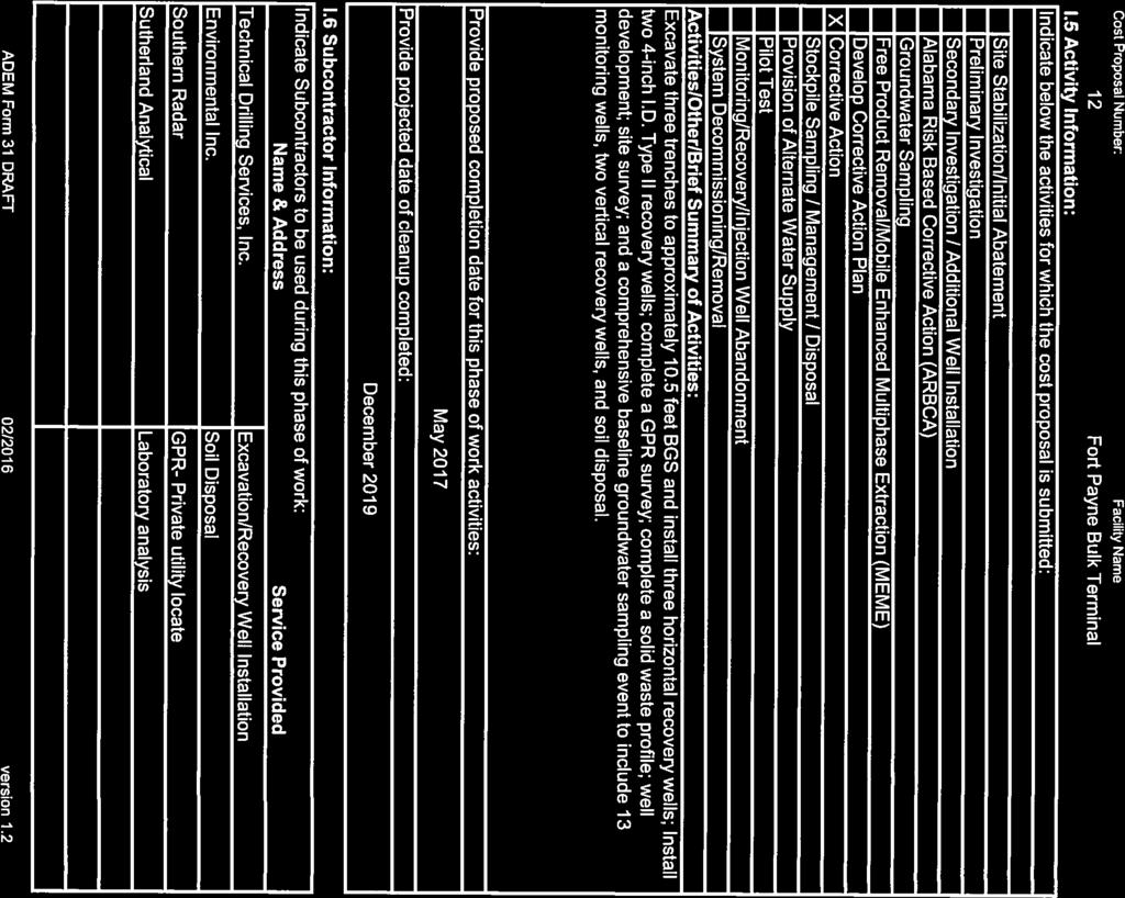
183

184


185

186
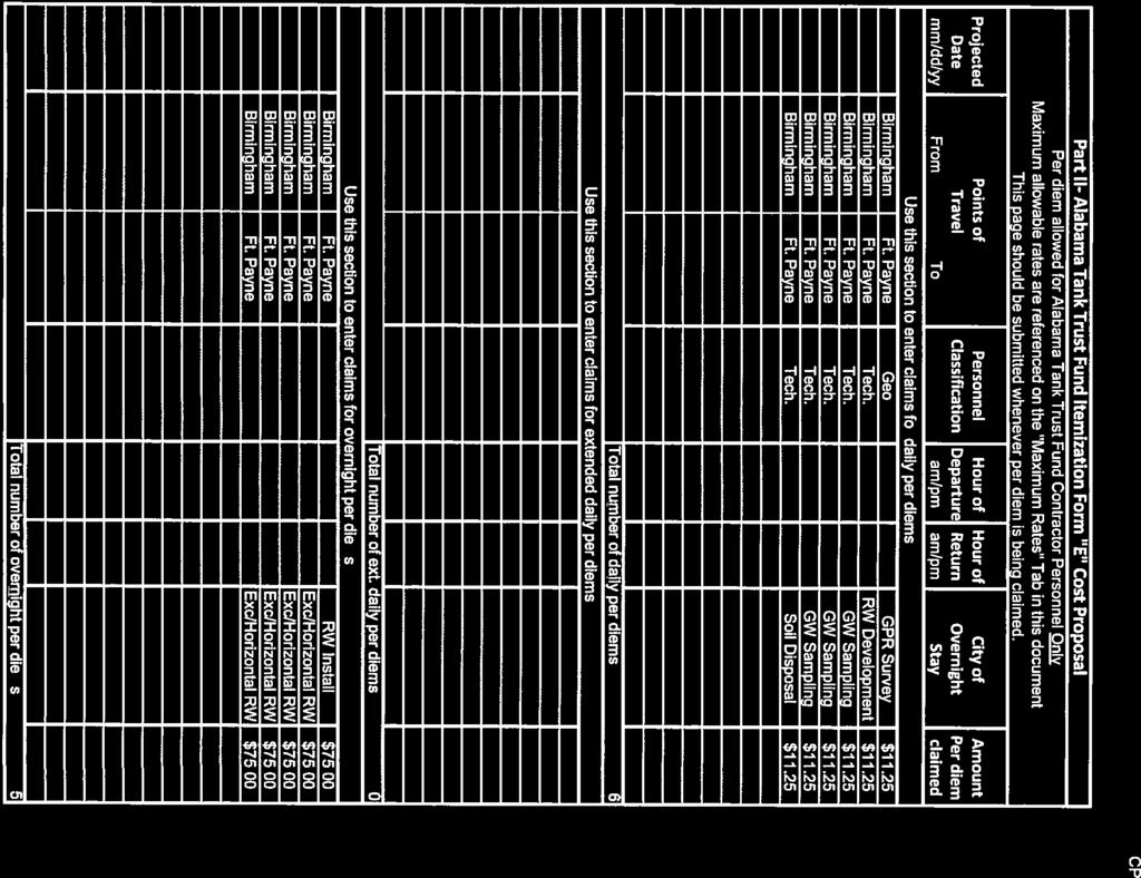

187


188
189 APPENDIX H COST PROPOSAL NO. 13 FIRST QUARTER MEME EVENTS
190

191

192


193


194
195 APPENDIX I COST PROPOSAL NO. 14 SECOND QUARTER RNA/MEME AND EFFECTIVENESS MONITORING

196

197


198


199
200


201
CORRECTIVE ACTION PLAN DEVELOPMENT (COST PROPOSAL NO. 12)
") ADREUSA CORRECTIVE ACTION PLAN DEVELOPMENT (COST PROPOSAL NO. 12) FRIDAY OIL COMPANY, INC. NORTHPORT SHELL FOOD MART 1325 LURLEEN B. WALLACE BOULEVARD NORTH NORTHPORT, ALABAMA FACILITY I.D. NO. 11944-125-013231
ADREUSA CORRECTIVE ACTION PLAN DEVELOPMENT (COST PROPOSAL NO. 12) FRIDAY OIL COMPANY, INC. NORTHPORT SHELL FOOD MART 1325 LURLEEN B. WALLACE BOULEVARD NORTH NORTHPORT, ALABAMA FACILITY I.D. NO. 11944-125-013231
Hard Hat Services ph: hardhatinc.com 932 N. Wright St., Suite 160 Naperville, IL 60563
 Interstate Power and Light Company Ottumwa Generation Station CCR Surface Impoundment Annual Inspection Report 154.018.015.003 Report issued: July 03, 2017 Hard Hat Services ph: 877-630-7428 hardhatinc.com
Hard Hat Services ph: hardhatinc.com 932 N. Wright St., Suite 160 Naperville, IL 60563
 Interstate Power and Light Company Ottumwa Generation Station CCR Surface Impoundment Annual Inspection Report 154.018.012.003 Report issued: December 21, 2016 Hard Hat Services ph: 877-630-7428 hardhatinc.com
METHOD 21 - DETERMINATION OF VOLATILE ORGANIC COMPOUND LEAKS. 1.2 Scope. This method is applicable for the
 1151 METHOD 21 - DETERMINATION OF VOLATILE ORGANIC COMPOUND LEAKS 1.0 Scope and Application. 1.1 Analytes. Analyte Volatile Organic Compounds (VOC) CAS No. No CAS number assigned 1.2 Scope. This method
Construction Dewatering
 Construction Dewatering Introduction The control of groundwater is one of the most common and complicated problems encountered on a construction site. Construction dewatering can become a costly issue
Explosive gas migration monitoring for a sanitary landfill facility.
 3745-27-12 Explosive gas migration monitoring for a sanitary landfill facility. (A) Applicability and implementation. This rule applies to the following: (1) The owner or operator of a sanitary landfill
Revised Corrective Action Plan Part B
 Revised Corrective Action Plan Part B Remedial Action and Groundwater Monitoring At AAFES Car Care Center Former Underground Storage Tank Installations Numbers 257-261 Ft. Stewart, Georgia Facility Identification
October 16, GRDA CCR Landfill Compliance Report Grand River Dam Energy Center 8142 Hwy 412B PO Box 609 Chouteau, OK Dear Mr.
 October 16, 2018 Mr. Mike Bednar Superintendent of Environmental Compliance GRDA-Ecosystems and Education Center PO Box 70 420 Hwy 28 Langley, OK 74350-0070 RE: GRDA CCR Landfill Compliance Report Grand
CCR Landfill 2017 Annual Inspection Report NC1 Ash Disposal Area
 CCR Landfill 2017 Annual Inspection Report NC1 Ash Disposal Area Omaha Public Power District Nebraska City Station Nebraska City, Nebraska January 19, 2018 OPPD Nebraska City Station NC1 Ash Disposal Area
RULES OF THE OIL AND GAS PROGRAM DIVISION OF WATER RESOURCES CHAPTER DRILLING WELLS TABLE OF CONTENTS
 RULES OF THE OIL AND GAS PROGRAM DIVISION OF WATER RESOURCES CHAPTER 0400-52-06 DRILLING WELLS TABLE OF CONTENTS 0400-52-06-.01 Drilling Equipment 0400-52-06-.03 Casingheads 0400-52-06-.02 Blowout Prevention
METHOD 2E - DETERMINATION OF LANDFILL GAS PRODUCTION FLOW RATE. NOTE: This method does not include all of the
 287 METHOD 2E - DETERMINATION OF LANDFILL GAS PRODUCTION FLOW RATE NOTE: This method does not include all of the specifications (e.g., equipment and supplies) and procedures (e.g., sampling and analytical)
INADVERTENT RETURN PLAN FOR HORIZONTAL DIRECTIONAL DRILLING (HDD)
") INADVERTENT RETURN PLAN FOR HORIZONTAL DIRECTIONAL DRILLING (HDD) FACILITY OPERATOR: NextEra Energy Resources, LLC 700 Universe Boulevard Juno Beach, FL 33408 For Horizontal Directional Drilling Contents
INADVERTENT RETURN PLAN FOR HORIZONTAL DIRECTIONAL DRILLING (HDD) FACILITY OPERATOR: NextEra Energy Resources, LLC 700 Universe Boulevard Juno Beach, FL 33408 For Horizontal Directional Drilling Contents
D.B. Wilson Station CCR Landfill
 D.B. Wilson Station CCR Landfill Disposal of Coal Combustion Residuals (CCR) from Electric Utilities Final Rule Closure and Post-closure Care Plan October 11, 2016 Prepared By: Project ID: 160030A Big
22. Specialty Valves.
 22. Specialty Valves. a. Types of Specialty Valves. 1) Use of the following specialty valves is covered in this section: Altitude Valve, Pressure Reducing Valve, Pressure Relief Valve, Swing Check Valve,
CCR Closure Plan. CCR Certification: Written Closure Plan (b) & (c) for the. Landfill Sedimentation Pond. A. B. Brown Generating Station
 & (c) for the. Landfill Sedimentation Pond. A. B. Brown Generating Station") Submitted to Southern Indiana Gas & Electric Company dba Vectren Power Supply, Inc. (SIGECO) One Vectren Square Evansville, IN 47708 Submitted by AECOM 525 Vine Street, Suite 1800 Cincinnati, Ohio 45202
Submitted to Southern Indiana Gas & Electric Company dba Vectren Power Supply, Inc. (SIGECO) One Vectren Square Evansville, IN 47708 Submitted by AECOM 525 Vine Street, Suite 1800 Cincinnati, Ohio 45202
BROWNFIELD ASSESSMENT, REDEVELOPMENT & REMEDIATION
 BROWNFIELD ASSESSMENT, REDEVELOPMENT & REMEDIATION 1 HOW ENVIRONMENTAL SITE ASSESSMENTS (PHASE I) AFFECT THE PURCHASE OR TRANSFER OF ANY PROPERTY 1 Standard 1 Sunshine State Standards: SS.A.1.4.4, SS.C.1.4
Air Eliminators and Combination Air Eliminators Strainers
 Description Air Eliminators and Combination Air Eliminator Strainers are designed to provide separation, elimination and prevention of air in piping systems for a variety of installations and conditions.
Annual CCR Landfill Inspection OML Existing Landfill OML Expansion Phase 1
 Annual CCR Landfill Inspection OML Existing Landfill OML Expansion Phase 1 Ottumwa-Midland Landfill Prepared for: Ottumwa-Midland Landfill 15300 130 th Street Ottumwa, Iowa 52501 Prepared by: SCS ENGINEERS
Slide 1. Slide 2. Slide 3. TANK CLOSURE (Decommissioning) Chapter 1: Industry/Regulatory Documents. Chapter 2: Safety Requirements
 Chapter 1: Industry/Regulatory Documents. Chapter 2: Safety Requirements") Slide 1 TANK CLOSURE (Decommissioning) Chapter 1: Industry/Regulatory Documents API Recommended Practice 1604 Closure of Underground Petroleum Storage Tanks (3rd Edition 1996) NEIWPCC - Tank Closure Without
Slide 1 TANK CLOSURE (Decommissioning) Chapter 1: Industry/Regulatory Documents API Recommended Practice 1604 Closure of Underground Petroleum Storage Tanks (3rd Edition 1996) NEIWPCC - Tank Closure Without
DUAL-VORTEX SEPARATOR. Inspection and Maintenance Guide
 DUAL-VORTEX SEPARATOR Inspection and Maintenance Guide Description The Dual-Vortex Separator (DVS) is a hydrodynamic stormwater treatment device used to remove pollutants from urban runoff. Impervious
CONFINED SPACE PROGRAM
 CONFINED SPACE PROGRAM Last updated: November 2017 1.0 PURPOSE Entry into a confined space represents a significant risk of serious injury or death to individuals not prepared for the hazards they may
If you have any questions or comments, please feel free to contact me at
 Phone: 256.847.0780 Fax: 256.8470905 matrixdesigngroup.com October 3, 2013 Mr. Eric Sanderson Chief, Solid Waste Branch, Land Division Alabama Department of Environmental Management P.O. Box 301463 Montgomery,
GUIDELINES FOR SLUG DISCHARGE MANAGEMENT PLAN (Abstract from EPA Guidance Manual)
") GUIDELINES FOR SLUG DISCHARGE MANAGEMENT PLAN (Abstract from EPA Guidance Manual) 1. An IU Slug Control Plan must include sufficient general information to enable the POTW to: (1) categorize and restrict
GUIDELINES FOR SLUG DISCHARGE MANAGEMENT PLAN (Abstract from EPA Guidance Manual) 1. An IU Slug Control Plan must include sufficient general information to enable the POTW to: (1) categorize and restrict
Maine Department of Environmental Protection (MEDEP) Stone Farm, Arundel Sample Collection - Data Report Summary Report Date: June 15, 2017
 Stone Farm, Arundel Sample Collection - Data Report Summary Report Date: June 15, 2017") Maine Department of Environmental Protection (MEDEP) Stone Farm, Arundel Sample Collection - Data Report Summary Report Date: June 15, 2017 --------------------------------------------------------------------------------------------------------------------------
Maine Department of Environmental Protection (MEDEP) Stone Farm, Arundel Sample Collection - Data Report Summary Report Date: June 15, 2017 --------------------------------------------------------------------------------------------------------------------------
METHOD 25A - DETERMINATION OF TOTAL GASEOUS ORGANIC CONCENTRATION USING A FLAME IONIZATION ANALYZER
 1250 METHOD 25A - DETERMINATION OF TOTAL GASEOUS ORGANIC CONCENTRATION USING A FLAME IONIZATION ANALYZER 1.0 Scope and Application. 1.1 Analytes. Analyte CAS No. Sensitivity Total Organic Compounds N/A
NSPS SUBPART Ka Check-off Form JULY 11, LAFAYETTE ROAD NO., ST. PAUL, MN
 520 LAFAYETTE ROAD NO., ST. PAUL, MN 55155-4194 NSPS FORM NSPS-Ka NSPS SUBPART Ka Check-off Form JULY 11, 2005 I. Introduction An owner or operator may fill in this form in replacement of a highlighted
TABLE OF CONTENTS LEGAL NOTICE
 Closure Plan for Existing CCR Revision: 1 Surface Impoundments Page No. i TABLE OF CONTENTS 1. INTRODUCTION... 1 2. PROPOSED CCR IMPOUNDMENT CLOSURE PROCEDURE... 3 3. PROPOSED COVER SYSTEM... 4 4. ESTIMATED
OREGON HEALTH. Systems Public Water Supply Systems Community Water Supply Systems Source Water Protection
 In the administration of ORS 537.505 to 537.795, the Director of the Water Resources Department has statutory authority under the provisions of ORS 537.780 "to prescribe and enforce general standards for
TABLE OF CONTENTS PART 2 - CONFINED SPACES
 May 11, 2006 TABLE OF CONTENTS PART 2 - CONFINED SPACES Page DEFINITIONS... 2-1 GENERAL... 2-2 RESPONSIBILITIES... 2-2 HAZARD ASSESSMENT AND WORK PROCEDURES... 2-3 IDENTIFICATION AND ENTRY PERMITS... 2-3
Consult with manufacturers concerning permeation of the pipe walls, jointing materials, valve seats, etc.
 Design Manual Chapter 4 - Water Mains 4C - Facility Design 4C-1 Facility Design A. General Water mains and appurtenances, including hydrants and valves, should be provided along all streets including connections
ENGINEER S CERTIFICATION OF AQUIFER SEPARATION DEMONSTRATION (40 CFR )
") PLATTE RIVER POWER AUTHORITY RAWHIDE ENERGY STATION BOTTOM ASH TRANSFER (BAT) IMPOUNDMENTS LARIMER COUNTY, CO ENGINEER S CERTIFICATION OF AQUIFER SEPARATION DEMONSTRATION (40 CFR 257.60) FOR COAL COMBUSTION
PLATTE RIVER POWER AUTHORITY RAWHIDE ENERGY STATION BOTTOM ASH TRANSFER (BAT) IMPOUNDMENTS LARIMER COUNTY, CO ENGINEER S CERTIFICATION OF AQUIFER SEPARATION DEMONSTRATION (40 CFR 257.60) FOR COAL COMBUSTION
2016 Annual Inspection Report
 2016 Annual Inspection Report for Compliance with the Coal Combustion Residuals Rule (40 CFR Part 257) Pawnee Station 14940 Morgan County Road 24 Brush, Colorado 80723 January 18, 2017 Table of Contents
TABLE OF CONTENTS LEGAL NOTICE
 Surface Impoundments Page No. i TABLE OF CONTENTS 1. INTRODUCTION... 1 2. PROPOSED CCR IMPOUNDMENT CLOSURE PROCEDURE... 3 3. PROPOSED COVER SYSTEM... 4 4. ESTIMATED MAXIMUM INVENTORY OF CCR... 4 5. ESTIMATED
EPA R6 Dive Team Operations Report. San Jacinto Waste Pits Channelview, TX December 9-10, 2015
 EPA R6 Dive Team Operations Report San Jacinto Waste Pits Channelview, TX December 9-10, 2015 BACKGROUND The San Jacinto River Waste Pit Site history has been documented in several documents prepared for,
1 Exam Prep NFPA 99 Health Care Facilities Questions and Answers (Plumbing Contractor)
") 1 Exam Prep NFPA 99 Health Care Facilities Questions and Answers (Plumbing Contractor) 1. According to NFPA 99, SCFM is an acronym for. a) Surface Conditions at Fahrenheit Mercury b) Standard Conditions
1 Exam Prep NFPA 99 Health Care Facilities Questions and Answers (Plumbing Contractor) 1. According to NFPA 99, SCFM is an acronym for. a) Surface Conditions at Fahrenheit Mercury b) Standard Conditions
Aquatic Facilities Water Spray/Play Ground Application, Design & Operating Requirements Environmental Health Guide
 Aquatic Facilities Water Spray/Play Ground Application, Design & Operating Requirements Environmental Health Guide Water Play/Spray Grounds are aquatic facilities where patrons (primarily children) become
FLAMMABLE GASES AND FLAMMABLE CRYOGENIC FLUIDS
 CHAPTER 35 FLAMMABLE GASES AND FLAMMABLE CRYOGENIC FLUIDS SECTION 3501 GENERAL 3501.1 Scope. The storage and use of flammable gases shall be in accordance with this chapter. Compressed gases shall also
Notice of Intent to Close Inactive CCR Surface Impoundments
 Notice of Intent to Close Inactive CCR Surface Impoundments Virginia Electric and Power Company Possum Point Power Station Coal Combustion Residual Surface Impoundments A, B, C, D, and E Dumfries, Virginia
SITE S7: EMBANKMENT FAILURE WEST OF MILLARVILLE
 LANDSLIDE RISK ASSESSMENT SOUTHERN REGION SITE S7: EMBANKMENT FAILURE WEST OF MILLARVILLE LEGAL LOCATION: LSD 4-3-21-4 W5M and 1-4-21-4 W5M REFERENCE LOCATION ALONG HIGHWAY The slide area is located between
Annex E Bridge Pier Protection Plan
 Annex E Bridge Pier Protection Plan Table E1 Bridge Types and Locations Table E2 Flow Conditions For River Sections Figure E1 Bridge Abutment Protection Figure E2 Bridge Pier Protection Figure E3 Central
TEMPLE UNIVERSITY ENVIRONMENTAL HEALTH AND RADIATION SAFETY
 Page 1 of 9 ISSUED: 5/00 REVISED: 08/06 Introduction Purpose: In accordance with applicable regulations and Temple University, this policy was developed to minimize exposure to Ethylene Oxide. Applicability
TAO Safety Policy No. HS-5.1 Page 1 of 15 Revision No. 2 Revision Date: July 19, 2005
 TAO Safety Policy No. HS-5.1 Page 1 of 15 Revision No. 2 1.0 OVERVIEW This safety policy provides guidance for conducting trenching and excavation activities at project sites. Emphasis is placed on sloping
STANDARD OPERATING PROCEDURES
 PAGE: 1 of 9 CONTENTS 1.0 SCOPE AND APPLICATION 2.0 METHOD SUMMARY 3.0 SAMPLE PRESERVATION, CONTAINERS, HANDLING AND STORAGE 3.1 Canister Receipt 3.2 Canister Storage 4.0 INTERFERENCE AND POTENTIAL PROBLEMS
2018 Annual Inspection Report
 2018 Annual Inspection Report for Compliance with the Coal Combustion Residuals Rule (40 CFR Part 257) Comanche Station 2005 Lime Road Pueblo, Colorado 81006 January 18, 2019 Table of Contents Certification...
OIL AND GAS DOCKET NO
 OIL AND GAS DOCKET NO. 09-0241077 THE APPLICATION OF GILBOW TANK TRUCK SERVICE, INC., TO DISPOSE OF OIL AND GAS WASTE BY INJECTION INTO A POROUS FORMATION NOT PRODUCTIVE OF OIL OR GAS, GILBOW WELL NO.
Dry Hydrants. The installation of a non-pressurized pipe system into local water sources provides a ready means of supplying water to fire engines.
 Dry Hydrants What is a Dry Hydrant? A dry hydrant is a non-pressurized pipe system permanently installed in existing lakes, ponds and streams that provides a suction supply of water to a fire department
TABLE OF CONTENTS 1.0 INTRODUCTION PLAN CERTIFICATION (B)(4) 1
(4) 1") TABLE OF CONTENTS 1.0 INTRODUCTION 1 2.0 PLAN CERTIFICATION 257.102(B)(4) 1 3.0 WRITTEN CLOSURE PLAN 2 3.1 Narrative 2 3.2 CCR Removal 2 3.3 CCR Left in Place 3 3.4 Maximum CCR Inventory 3 3.5 Maximum
TABLE OF CONTENTS 1.0 INTRODUCTION 1 2.0 PLAN CERTIFICATION 257.102(B)(4) 1 3.0 WRITTEN CLOSURE PLAN 2 3.1 Narrative 2 3.2 CCR Removal 2 3.3 CCR Left in Place 3 3.4 Maximum CCR Inventory 3 3.5 Maximum
Item 404 Driving Piling
 Item Driving Piling 1. DESCRIPTION Drive piling. 2. EQUIPMENT 2.1. Driving Equipment. Use power hammers for driving piling with specified bearing resistance. Use power hammers that comply with Table 1.
CLEANING, INSPECTION, AND TESTING OF SEWERS
 CLEANING, INSPECTION, AND TESTING OF SEWERS PART 1 - GENERAL 1.01 SECTION INCLUDES A. Cleaning, Inspecting, and Testing Sanitary Sewers B. Cleaning, Inspecting, and Testing Storm Sewers C. Cleaning and
APPENDIX A1 - Drilling and completion work programme
 APPENDIX A1 - Drilling and completion work programme Information about the well and drilling To the extent possible, the international system of units (SI) should be adhered to, and the drilling programme
SECTION PRESSURE TESTING OF PIPING
 SECTION 15044 PRESSURE TESTING OF PIPING PART 1 - GENERAL 1.01 DESCRIPTION A. Scope of Work: This section specifies the leakage and pressure testing of piping. B. Testing Records: PART 2 - PRODUCTS 2.01
SPILL CONTINGENCY AND EMERGENCY RESPONSE PLAN
 SPILL CONTINGENCY AND EMERGENCY RESPONSE PLAN All rights reserved. No part of this publication may be reproduced or transmitted in any form or by any means, electronic or mechanical, without the written
CCR Landfill 2015 Annual Inspection Report NC1 Ash Disposal Area
 CCR Landfill 21 Annual Inspection Report NC1 Ash Disposal Area Omaha Public Power District Nebraska City Station Nebraska City, Nebraska January 19, 216 OPPD Nebraska City Station NC1 Ash Disposal Area
Juneau Douglas Harbor
 Juneau Douglas Harbor Douglas Harbor Page 2 of 8 Condition of Improvements 31 December 2015 Douglas Harbor, Alaska (CWIS No. 072789, 180942) Authorization Rivers and Harbors Act, 3 July 1958 (House Doc.
Suitable Applications Check dams may be appropriate in the following situations: To promote sedimentation behind the dam.
 Categories EC Erosion Control SE Sediment Control TC Tracking Control WE Wind Erosion Control Non-Stormwater NS Management Control Waste Management and WM Materials Pollution Control Legend: Primary Category
Annual CCR Landfill Inspection. Lansing Landfill. Interstate Power and Light Company. Prepared for:
 Annual CCR Landfill Inspection Lansing Landfill Prepared for: Interstate Power and Light Company Lansing Generating Station 2320 Power Plant Drive Lansing, Iowa 52151 Prepared by: SCS ENGINEERS 2830 Dairy
Nome Harbor Page 2 of 12
 Nome Harbor Nome Harbor Page 2 of 12 Condition of Improvements 30 December 2015 Nome Harbor, Alaska (CWIS No. 010422, 012270, 072742, 087755) Authorization (1) Rivers and Harbors Act, 8 August 1917 (House
Mr. Michael Malone CPS Energy 145 Navarro Street, Mail Drop San Antonio, Texas Project No
 October 17, 2016 Mr. Michael Malone CPS Energy 145 Navarro Street, Mail Drop 100406 San Antonio, Texas 78296 Project No. 0352436 Subject: Compilation of Construction History Calaveras Power Station San
Appendix B Harris County Standard Operating Procedure for Determining In Situ Hydraulic Performance of High Flow Rate Bioretention Media
 Objective Appendix B Harris County Standard Operating Procedure for Determining In Situ Hydraulic Performance of High Flow Rate Bioretention Media Provide as-built confirmation of proper installation and
Appendix A. Imbrium Systems Jellyfish Filter Inspection and Maintenance Information
 Appendix A Imbrium Systems Jellyfish Filter Inspection and Maintenance Information Jellyfish Filter Inspection and Maintenance Regular inspection and maintenance are proven, cost-effective ways to maximize
CCR Fugitive Dust Control Plan
 CCR Fugitive Dust Control Plan Omaha Public Power District North Omaha Station Omaha, Nebraska October 16, 2015 OPPD North Omaha Station CCR Landfill Fugitive Dust Control Plan Table of Contents Revision
SITE TESTING STANDARDS FOR METHANE
 INFORMATION BULLETIN / PUBLIC - BUILDING CODE REFERENCE NO.: 91.7104.1 Effective: 11-30-04 DOCUMENT NO. P/BC 2002-101 Revised: Previously Issued As: None SITE TESTING STANDARDS FOR METHANE This Infmation
General Inspection Guidance for Waste Management Units Requiring Air Emission Controls Under RCRA Air Standard Subpart CC
 United States Environmental Protection Agency RCRA Programs Branch Region IV Atlanta, GA CAA/RCRA Air Rules 27 November 2000 General Inspection Guidance for Waste Management Units Requiring Air Emission
PENNSYLVANIA DEPARTMENT OF ENVIRONMENTAL PROTECTION
 Page 1 of 9 PENNSYLVANIA DEPARTMENT OF ENVIRONMENTAL PROTECTION COMPLIANCE DEMONSTRATION INSTRUCTIONS FOR THE CATEGORY NO. 38 AIR QUALITY PERMIT EXEMPTION CRITERIA The Category No. 38 exemption criteria
HAZARDOUS WASTE OPERATIONS AND EMERGENCY RESPONSE
 Page 1 of 10 HAZARDOUS WASTE OPERATIONS AND EMERGENCY RESPONSE 1.0 SCOPE This Performance Assessment Guide for Hazardous Waste Operations and Emergency Response (HAZWOPER) will be used to carry out the
Excavations and Trenches
 Purpose Excavation and trenching are among the most hazardous work activities undertaken by the TNRD. This document outlines general requirements and specific safe work procedures to ensure the health
Responding to Natural Gas Pipeline Emergencies
 Responding to Natural Gas Pipeline Emergencies Who is Florida Gas Transmission? Florida Gas Transmission operates nearly 5,000-miles of interstate natural gas transmission pipelines, a system that extends
Automated Determination of Dissolved Gases in Water Anne Jurek. Abstract: Discussion:
 Automated Determination of Dissolved Gases in Water Anne Jurek Abstract: The RSK-175 standard operating procedure was developed in order to determine the amount of dissolved gas in water. Due to the expansion
Closure Plan for CCR Surface Impoundments
 Closure Plan for CCR Surface Impoundments B.L. England Generating Station Beesley s Point, New Jersey April 17, 2018 Prepared For RC Cape May Holdings, LLC 900 North Shore Road Beesley s Point, New Jersey
1995 Metric CSJ SPECIAL PROVISION ITEM 7. Legal Relations And Responsibilities To The Public
 1995 Metric CSJ 0915-12-242 SPECIAL PROVISION TO ITEM 7 Legal Relations And Responsibilities To The Public For this project, Item 7 "Legal Relations and Responsibilities to the Public", of the Standard
Initial Annual CCR Landfill Inspection OML Existing Landfill OML Expansion Phase 1
 Initial Annual CCR Landfill Inspection OML Existing Landfill OML Expansion Phase 1 Ottumwa-Midland Landfill Prepared for: Ottumwa-Midland Landfill 15300 130 th Street Ottumwa, Iowa 52501 Prepared by: SCS
(b) Venting or flaring shall only be authorized by the Commission under the following circumstances:
 Venting or flaring shall only be authorized by the Commission under the following circumstances:") Chapter 3, Section 39. Authorization for Flaring and Venting of Gas. (a) Venting or flaring must be in accordance with Commission requirements to prevent waste as specified in W.S. 30-5-101(a)(i)(G), 102(a),
Chapter 3, Section 39. Authorization for Flaring and Venting of Gas. (a) Venting or flaring must be in accordance with Commission requirements to prevent waste as specified in W.S. 30-5-101(a)(i)(G), 102(a),
VACUUM TESTING PRECAST CONCRETE MANHOLES
 1 OF 5 testing is a quick, safe and practical way to validate manhole system integrity. Manhole sections can be tested at the precast concrete plant prior to delivery or on site prior to backfilling. Here
Environmental Health & Safety Policy & Procedure #35
 Environmental Health & Safety Policy & Procedure #35 TITLE: PURPOSE: SCOPE: EMERGENCY EYEWASH AND SHOWER EQUIPMENT The purpose of this policy is to establish minimum requirements regarding the design,
Health, Safety, Security and Environment
 Document owner and change code Document Owner Aaron Perronne Title HSSE Manager Mark X Change Code Description X N/A First Issue A Typographical/Grammatical correction; formatting change; text clarification-no
EQUIPMENT AND MATERIALS
 SCUD Procedure # EMER004 Page 1 of 5 SCOPE AND PURPOSE This procedure is to provide performing outside leak investigations with the necessary procedures for prompt and effective response and to protect
CCR CLOSURE PLAN Sibley Slag Settling Impoundment Sibley Generating Station East Johnson Rd Sibley, Missouri
 CCR CLOSURE PLAN Sibley Slag Settling Impoundment Sibley Generating Station 33200 East Johnson Rd Sibley, Missouri KCP&L Greater Missouri Operations Company October 14, 2016 TABLE OF CONTENTS SECTION 1
Safety Regulations and Procedures GENERAL SAFETY Confined Spaces - S New 11/96. To provide guidance for the safe entry of confined spaces.
 CONFINED SPACES PURPOSE REGULATION To provide guidance for the safe entry of confined spaces. Washington Administrative Code - WAC 296-62, Part 'M,' Confined Spaces. RESPONSIBILITY Safety Services test
La Crescent Township Zoning Ordinance
 La Crescent Township Zoning Ordinance Table of Contents SECTION 1 ~ PREAMBLE, TITLE, SHORT TITLE AND PURPOSE... 1 0101 Preamble... 1 0102 Title... 1 0103 Short Title... 1 0104 Purpose... 1 SECTION 2 ~
Simplified Start-Up Checklist For Fully-Pressurized Seasonal Systems
 Water System Information Water System Name: Simplified Start-Up Checklist For Fully-Pressurized Seasonal Systems Division of Drinking and Ground Waters (Revised 8/17/2017) Date Checklist Completed (mm/dd/yyyy):
ITEM 400 STRUCTURAL EXCAVATION AND BACKFILL
 AFTER MARCH 1, 2012 ITEM 400 STRUCTURAL EXCAVATION AND BACKFILL 400.1 Description. This item shall govern for all excavation required for the construction of all structures, except pipe or box sewers for
Laboratory Hardware. Custom Gas Chromatography Solutions WASSON - ECE INSTRUMENTATION. Engineered Solutions, Guaranteed Results.
 Laboratory Hardware Custom Gas Chromatography Solutions Engineered Solutions, Guaranteed Results. WASSON - ECE INSTRUMENTATION Laboratory Hardware Wasson-ECE Instrumentation offers hardware-only solutions
Monte Besler Consultant FracN8R Consulting LLC UNITED STATES
 Monte Besler Consultant FracN8R Consulting LLC UNITED STATES Engineered Safety and Environmental Aspects of Well Construction and Fracturing Design Monte Besler FRACN8R Consulting, LLC Surface Considerations
Section 38 Brieser Construction SH&E Manual
 Brieser Construction SH&E Manual April 2015 The purpose of this plan is to document spill prevention and response requirements. Spill Prevention https://brieserconstruction.sharepoint.com/safety/safety/safety
Northern Indiana Public Service Company Michigan City Generating Station Primary Settling Pond Number Annual RCRA CCR Unit Inspection Report
 REPORT Northern Indiana Public Service Company Michigan City Generating Station Primary Settling Pond Number 2 2018 Annual RCRA CCR Unit Inspection Report Submitted to: Northern Indiana Public Service
IDEM Indiana Department of Environmental Management Office of Land Quality P.O. Box 6015 Indianapolis, IN OLQ PH: (317)
") IDEM Indiana Department of Environmental Management Office of Land Quality P.O. Box 6015 Indianapolis, IN 46206-6015 OLQ PH: (317) 232-8941 Information SUBPART CC AIR EMISSION STANDARDS (40 CFR 264.1080
IDEM Indiana Department of Environmental Management Office of Land Quality P.O. Box 6015 Indianapolis, IN 46206-6015 OLQ PH: (317) 232-8941 Information SUBPART CC AIR EMISSION STANDARDS (40 CFR 264.1080
Hazardous Materials Management. Presented by. James E. Roughton, MS, CSP, CRSP, CHMM.
 Hazardous Materials Management Presented by. James E. Roughton, MS, CSP, CRSP, CHMM. Hazardous Waste Operations And Emergency Response (HAZWOPER) 29 CFR 1910.120 Scope Clean-up Operations At Uncontrolled
Chapter 11. Culverts and Bridges Design Checklist for Culvert Design
 Yes No N/A Design Requirements I. GENERAL DESIGN GUIDELINES Chapter 11. Culverts and Bridges A. Culvert design is in accordance with the Culverts chapter of Volume 2 of the UDFCD Manual for additional
PERKFILTER. Inspection and Maintenance Guide
 PERKFILTER Inspection and Maintenance Guide PerkFilter Media Filtration System Description The PerkFilter is a stormwater treatment device used to remove pollutants from urban runoff. Impervious surfaces
STANDARD OPERATING PROCEDURES
 PAGE: 1 of 14 CONTENTS 1.0 SCOPE AND APPLICATION 2.0 METHOD SUMMARY 3.0 SAMPLE PRESERVATION, CONTAINERS, HANDLING, AND STORAGE 4.0 INTERFERENCES AND POTENTIAL PROBLEMS 5.0 EQUIPMENT/APPARATUS 5.1 Subatmospheric
Fire Apparatus Operator: ARFF
 Fire Apparatus Operator: ARFF Skill Sheet Package Based on NFPA 1002: Standard on Fire Apparatus Driver/ Operator Professional Qualifications, 2017 Edition. Alabama Fire College November 26, 2018 Alabama
the annulus between the second casing string and the surface casing [must be] open to the atmosphere in the manner described in subsection (2).
![the annulus between the second casing string and the surface casing [must be] open to the atmosphere in the manner described in subsection (2).](/thumbs/81/84166815.jpg "the annulus between the second casing string and the surface casing [must be] open to the atmosphere in the manner described in subsection (2).") Bulletin 2011-35 December 20, 2011 Surface Casing Vent Requirements for Wells This bulletin clarifies Section 6.100(4) of the Oil and Gas Conservation Regulations (OGCR) and provide additional surface
Bulletin 2011-35 December 20, 2011 Surface Casing Vent Requirements for Wells This bulletin clarifies Section 6.100(4) of the Oil and Gas Conservation Regulations (OGCR) and provide additional surface
Lecture 10 : Sewer Appurtenances
 1 P age Module 8 : Sewer Appurtenances Lecture 10 : Sewer Appurtenances 2 P age The structures, which are constructed at suitable intervals along the sewerage system to help its efficient operation and
RESIDENTIAL SWIMMING POOLS AND SPAS A GUIDE FOR HOMEOWNERS
 RESIDENTIAL SWIMMING POOLS AND SPAS A GUIDE FOR HOMEOWNERS City of Redding 777 Cypress Avenue Redding CA 96001 Telephone: (530) 225-4013 FAX: (530) 225-4360 A Swimming Pool is any body of water 18 inches
HEALTH AND SAFETY PROGRAM 201 HOT TAP PERMIT/FILLET WELD REPAIRS
 Page 1 of 15 1.0 PURPOSE 1.1. Axiall, Plaquemine Complex, has developed this Hot Tap Permit Program to eliminate potential accidents, injuries, and to enhance employee protection. 1.2. To provide for the
SWIMMING POOL, SPA, & HOT TUB GUIDELINES
 SWIMMING POOL, SPA, & HOT TUB GUIDELINES A. Adopted construction codes and installation requirements 1. 2015 edition of the International Residential Code and Appendix Q, 2. 2014 edition of the National
CONFINED SPACE ENTRY PROGRAM
 CONFINED SPACE ENTRY PROGRAM 2003 ENVIRONMENTAL HEALTH AND SAFETY/RISK MANAGEMENT p1 Rev. 01/07/2003 wrk Environmental Health and Safety/Risk Management CSUCI Confined Space Entry Program TABLE OF CONTENTS
Laboratory Hardware. Custom Gas Chromatography Solutions WASSON - ECE INSTRUMENTATION. Custom solutions for your analytical needs.
 Laboratory Hardware Custom Gas Chromatography Solutions Custom solutions for your analytical needs. Laboratory Hardware Wasson-ECE Instrumentation offers hardware-only solutions for advanced chromatography
Cordova Harbor Page 2 of 9
 Cordova Harbor Cordova Harbor Page 2 of 9 Condition of Improvements 30 December 2017 Cordova Harbor, Alaska (CWIS No. 087136, 087186, 087711) Authorization Rivers and Harbors Act, 30 August 1935 (R & H
DIRECTIONAL DRILLING
 DIRECTIONAL DRILLING 1. General. Installation of pipelines through the levee embankment using directional drilling technology is prohibited. Installation of pipelines through a flood control project foundation