Center for National Response Operational Test Report for the Tempest Technology Corporation Mobile Ventilation Unit (MVU)
|
|
|
- Miranda Little
- 6 years ago
- Views:
Transcription

1 Center for National Response Operational Test Report for the Tempest Technology Corporation Mobile Ventilation Unit (MVU) Test Series CNR June, 2002 Prepared by: Center for National Response Operational Testing Division Science Applications International Corporation 8301 Greensboro Drive, Suite 120 McLean, Virginia Prepared for: National Guard Bureau 9 August, 2002
2 Disclaimer The findings in this report are not to be construed as an official National Guard Bureau position unless so designated by other authorized documents. Trade Names Use of trade names or manufacturers in this report does not constitute an official endorsement or approval of the use of such commercial hardware or software. 1
3 Center for National Response Test Report Table of Contents Executive Summary Introduction Testing Objective Testing Authority Test Concepts Unit Under Test Description Unique Personnel Requirements Test Series CNR Tempest Technologies MVU Schedule Participants Test Objectives, Criteria, and Procedures Operational Test Results Baseline Test PPV (South to North) Operational Testing PPV (North to South) Operational Testing PPV (South moving North) Operational Testing Decontamination of Personnel Utilizing UUT and Misting Ring Decontamination of Vehicles Utilizing UUT and Misting Ring Conclusions Analysis of System s Capabilities and Limitations Lessons Learned Suggested Refinements...21 Appendices Appendix A - Test Data Sheets...23 Appendix B - Test Photos...42 Appendix C - Operational Test Schedule...45 Appendix D - UUT Specifications...46 Appendix E - Points of Contact...48 Appendix F - Acronyms and Abbreviations...49 Appendix G - References
4 Executive Summary The operational testing and evaluation program at the Center for National Response (CNR) is a multi-faceted program that encompasses a wide range of sophisticated operational testing and evaluation processes. These activities include a seamless integration of the exercise, operational testing, and evaluation procedures. The emphasis is on evaluating tools in a realistic operational environment with missions that responders will be tasked to accomplish. The Operational Test and Evaluation Program of the CNR conducted Test Series CNR of the Tempest Technology Corporation Mobile Ventilation Unit (MVU) on 27 June Test operators for this test series were firefighters from the 130 th Airlift Wing (AW), West Virginia Air National Guard (WVANG). None of the operators had any previous experience operating the unit under test (UUT). The MVU provides positive pressure ventilation (PPV) in a large enclosed structure and can be mounted on a truck, trailer, or skid. A trailer mounted MVU was utilized for this test iteration. The MVU works by creating an air seal at the entrance point and pressurizing a structure. The resulting airflow blows clean, fresh air into the structure, forcing out heat, smoke, gasses and other contaminates. It can be used to ventilate any size or shape structure, as long as there is an entrance point for the clean air and an exit point for the contaminated air. Test objectives for Test Series CNR were to: (1) examine the utility of the MVU to materially aid civilian and military emergency responders in the conduct of the response and recovery phases of their mission in a tunnel environment; and (2) examine the utility of the MVU configured with the Tempest Misting Ring in decontamination applications. Test operators were pleased with the performance of the UUT. They found that, with limited training, the UUT was easy to operate in a simulated weapon of mass destruction (WMD) and emergency response environment. It provided them with an efficient way to clear a contained area of smoke in an expedient manner. The revised date on this test report is due to the removal of the "Limited Distribution" classification and serves to update the point of contact information. 3

5 1.0 Introduction 1.1 Testing Objective The Operational Test and Evaluation Program at the CNR is a multi-faceted program that encompasses a wide range of sophisticated operational testing and evaluation processes. These activities include a seamless integration of the exercise, operational testing, and evaluation procedures. These procedures are executed by integrating the operational testing and evaluation into an exercise scenario without altering the free play of the exercise. A comprehensive review of the operational testing and evaluation procedures are then documented in a test report; found herein. The test activities are designed to serve three key program objectives: Operational test and evaluation of equipment, technologies, and apparatus for effective use in large-scale hazardous material and WMD response operations; Provision of operational data for future development and improvement of technical capabilities by developers, vendors, or other program sponsors; and Provision of data and information for National Guard Bureau (NGB) and the consequence management community on the utility and effectiveness of the CNR in training and test support missions. Test objectives for Test Series CNR were to: (1) examine the utility of the MVU to materially aid civilian and military emergency responders in the conduct of the response and recovery phases of their mission in a tunnel environment; and (2) examine the utility of the MVU configured with the Tempest Misting Ring in decontamination applications. Figure 1-1 provides a picture of the Tempest Technologies MVU. Figure 1-1. Tempest Technologies MVU 4
6 1.2 Testing Authority In fiscal year 2000, Congress directed the U.S. Department of Defense (DoD) to establish a cost effective counterterrorism training program for first responders and concurrent testing of response apparatus and equipment at the [West Virginia] Memorial Tunnel. The CNR is currently under the direction of the NGB. The CNR program includes an integrated contractor support team comprised of a Program Management and Training and Exercise Division led by Titan Systems Corporation and a Testing Division led by Science Applications International Corporation (SAIC). The CNR test program will evolve and be implemented in accordance with the Consequence Management Program Integration Office (CoMPIO)-approved Implementation Plan (IPLAN), a dynamic planning document that reflects the priority training and testing needs to costeffectively serve the response community. The IPLAN provides the Government's authority for Titan and its Team to operate the Facility. SAIC works as part of the integrated program team for the conduct of training, exercise, and evaluation of individual, unit/organizational, and equipment technical operations. This support will occur continuously as each phase of the IPLAN is reviewed and approved by the U.S. Government and implemented by the program support team. 1.3 Test Concepts The Operational Test and Evaluation Program at the CNR is a multi-faceted program that encompasses a wide range of sophisticated operational testing and evaluation processes. These activities include a seamless integration of the exercise, operational testing, and evaluation procedures. These procedures are executed by integrating the operational testing and evaluation into the exercise scenario without altering the free play of the exercise. A detailed operational testing and evaluation period and After-Action Reviews (AAR) follow the exercise. This iteration of operational testing did not occur concurrently with an exercise. To ensure operational realism, test operators engaged in testing the UUT within a smoke-filled tunnel environment, simulating a tunnel fire, and in the South Portal Entrance area of the Tunnel to simulate a mass decontamination line. 1.4 Unit Under Test Description The MVU provides PPV for firefighters in a large, enclosed structure and works by creating an air-seal at the entrance point, thus pressurizing the structure. The resulting airflow blows clean, fresh air into the structure, forcing out heat, smoke, gasses, and other contaminants. It can be used to ventilate any size or shape structure, as long as there is an entrance point for the clean air and an exit point for the contaminated air. The unit can be mounted on a truck, trailer, or skid and has a Scissors Lift capable of an additional elevation of up to 10 feet (3,000 mm). The fan portion of the unit can rotate 360 and has a pitch of 35 (Up/Down). 1.5 Unique Personnel Requirements Personnel from the 130 th AW, WVANG operated the UUT. The operators had no previous experience operating the UUT. 5
7 2.0 Test Series CNR Tempest Technologies MVU 2.1 Schedule Operational Testing of the MVU was conducted on 27 June The schedule, with specific times for each test, is provided in Appendix D. 2.2 Participants Operational Test participants are identified in Table 2-1. Name and Organization SAIC Mickey Kirschenbaum, Test Director Allison Voight, Test Controller Brendon LaTurno, Test Controller Howard Murphy, Test Controller Forrest Church, Test Controller Dutch Thomas, Test Controller Titan Don Fike, CNR Safety Officer and Logistics Support 130 th AW/FD, WV-ANG Olaf Funfstuck II, Test Operator William Allen Gannon, Test Operator Tempest Technology Dexter Coffman, Manufacturer Representative Leroy Coffman, Manufacturer Representative Juergen Bader, Manufacturer Representative Tom Fox, Manufacturer Representative Table 2-1. Operational Test Participants 2.3 Test Objectives, Criteria, and Procedures Baseline Test Objective The objective of Test 1 was to determine the amount of time required to naturally clear the tunnel of smoke Criteria Test criteria were defined by the ability of natural airflow to clear the tunnel of smoke. All observations and anomalies were evaluated to determine their impact on mission performance. 6
8 Test Procedures Step 1: Determine wind speed and direction of natural air movement in the tunnel. Record all Step 2: Detonate a M-18 smoke grenade at the 1,400-foot marker. No observable. Step 3: Determine visual acuity at 1,400-foot marker and 2,800-foot marker (North Portal Entrance) and (2) wind speed at 700-foot marker, 1,400-foot marker, 2,100 foot marker, and 2,800 foot marker (North Portal Entrance). Record all Step 4: Using visual acuity at 1,400-foot marker and 2,800-foot marker, determine when tunnel is clear of all smoke. Record elapsed time and all Step 5: End test. No observations Data Required A record was made of all environmental parameters, operational conditions, and discrepancies between the planned test and the actual test during each step. Photographs were taken of various aspects of the operational test. A record was made of any discrepancies noted before, during, or after the inspection/functional checkout Data Analysis/Procedures An assessment of the facility was made before testing. All anomalies were addressed and, if possible, corrected or waived prior to the initiation of testing PPV (South to North) Operational Testing Objective The objective of Test 2 was to examine the ability of the operator to utilize the UUT to provide PPV and eliminate smoke from the tunnel Criteria Test criteria were defined by the ability of the operator to utilize the MVU to provide PPV and clear the tunnel of smoke. All observations and anomalies were evaluated to determine their impact on mission performance Test Procedures Step 1: Operator 1 conducts situational assessment of incident site. Observe operator actions and record all Step 2: Operators position UUT 75 feet from the South Portal Entrance. Observe operator actions and record all Step 3: Operators power up UUT and conduct baseline check of all systems functions. Observe operator actions and record all 7
9 Step 4: Initiate PPV. Observe operator actions. Record: (1) visual acuity at 1,400-foot marker and 2,800-foot marker (North Portal Entrance) and (2) wind speed at 700-foot marker, 1,400-foot marker, 2,100-foot marker, and 2,800-foot marker (North Portal Entrance). Step 5: UUT operates until tunnel is clear of all smoke. Observe operator actions and record time until smoke has cleared the tunnel. Step 6: Operator 1 conducts situational assessment of incident site. Observe and record all Step 7: Power down UUT and conduct baseline check of all systems functions. Observe operator actions and record all Data Required A record was made of all environmental parameters, operational conditions, and discrepancies between the planned test and the actual test during each step. Photographs were taken of various aspects of the operational test. A record was made of any discrepancies noted before, during, or after the inspection/functional checkout Data Analysis/Procedures An assessment of the UUT was made before testing. All anomalies were addressed and, if possible, corrected or waived prior to the initiation of testing. Based on observation and feedback from test operators, the utility of the UUT to accomplish the designated mission was determined. A comparative analysis of the UUT with similar products was not conducted PPV (North to South) Operational Testing Objective The objective of Test 3 was to examine the ability of the operator to utilize the UUT to provide PPV and eliminate smoke from the tunnel Test Criteria Test criteria were defined by the ability of the operator to utilize the MVU to provide PPV and clear the tunnel of smoke. All observations and anomalies were evaluated to determine their impact on mission performance Test Procedures Step 1: Operator 1 conducts situational assessment of incident site. Observe operator actions and record all Step 2: Operators position UUT 75 feet from North Portal Entrance. Observe operator actions and record all Step 3: Operators power up UUT and conduct baseline check of all systems functions. Observe operator actions and record all Step 4: Initiate PPV. Observe operator actions. Record: (1) visual acuity at 1,400-foot marker and 2,800-foot marker (North Portal Entrance) and (2) wind speed at 700-foot marker, 1,400-foot marker, 2,100-foot marker, and 2,800-foot marker (North Portal Entrance). 8
10 Step 5: UUT operates until tunnel is clear of all smoke. Observe operator actions and record time until smoke has cleared the tunnel. Step 6: Operator 1 conducts situational assessment of incident site. Observe and record all Step 7: Power down UUT and conduct baseline check of all systems functions. Observe operator actions and record all Data Required A record was made of all environmental parameters, operational conditions, and discrepancies between the planned test and the actual test during each step. Photographs were taken of various aspects of the operational test. A record was made of any discrepancies noted before, during or after the inspection/functional checkout Data Analysis/Procedures An assessment of the UUT was made before testing. All anomalies were addressed and, if possible, corrected or waived prior to the initiation of testing. Based on observation and feedback from test operators, the utility of the UUT to accomplish the designated mission was determined. A comparative analysis of the UUT with similar products was not conducted PPV (Moving North) Operational Testing Objective The objective of Test 4 was to examine the ability of the operator to utilize the UUT to by moving the UUT inside the tunnel to eliminate the smoke Test Criteria Test criteria were defined by the ability of the operator to utilize the MVU to provide PPV and clear the tunnel of smoke. All observations and anomalies were evaluated to determine their impact on mission performance Test Procedures Step 1: Operator 1 conducts situational assessment of incident site. Observe operator actions and record all Step 2: Operators position UUT at South Portal Entrance. Observe operator actions and record all Step 3: Operators power up UUT and conduct baseline check of all systems functions. Observe operator actions and record all Step 4: Initiate PPV. Observe operator actions and record wind speed at 1,400-foot marker. Step 5: Move UUT to 100-foot marker. Observe and record wind speed at 1400-foot marker. Step 6: Move UUT to 200-foot marker. Observe and record wind speed at 1,400-foot marker. Step 7: Move UUT to 300-foot marker. Observe and record wind speed at 1,400-foot marker. Step 8: Move UUT to 400-foot marker. Observe and record (1) wind speed at 1,400-foot marker and (2) visual acuity at 2,800-foot marker (North Portal Entrance). 9
11 Step 9: Move UUT to 500-foot marker. Observe and record (1) wind speed at 1,400 foot marker and (2) visual acuity at 2,800-foot marker (North Portal Entrance). Step 10: Move UUT to 600-foot marker. Observe and record (1) wind speed at 1,400-foot marker and (2) visual acuity at 2,800-foot marker (North Portal Entrance). Step 11: Move UUT to 700-foot marker. Observe and record (1) wind speed at 1,400-foot marker and (2) visual acuity at 2,800-foot marker (North Portal Entrance). Step 12: UUT operates until tunnel is clear of all smoke. Observe operator actions and record time until smoke has cleared the tunnel. Step 13: Operator 1 conducts situational assessment of incident site. Observe and record all Step 14: Power down UUT and conduct baseline check of all systems functions. Observe operator actions and record all Data Required A record was made of all environmental parameters, operational conditions, and discrepancies between the planned test and the actual test during each step. Photographs were taken of various aspects of the operational test. A record was made of any discrepancies noted before, during, or after the inspection/functional checkout Data Analysis/Procedures An assessment of the UUT was made before testing. All anomalies were addressed and, if possible, corrected or waived prior to the initiation of testing. Based on observation and feedback from test operators, the utility of the UUT to accomplish the designated mission was determined. A comparative analysis of the UUT with similar products was not conducted Decontamination of Personnel Utilizing UUT and Misting Ring Objective The objective of Test 5 was to examine the ability of the operator to utilize the UUT configured with the Misting Ring to decontaminate personnel Test Criteria Test criteria were defined by the degree and ease that the MVU can be used to decontaminate personnel. All observations and anomalies were evaluated to determine their impact on mission performance Test Procedures Step 1: Test Subjects are sprayed with florescent material. Using black light, photograph sprayed areas. Step 2: Operators establish a decontamination area at the South Portal Entrance. Observe operator actions and record all Step 3: Operators position UUT with Misting Ring 75 feet from South Portal Entrance. Observe operator actions and record all Step 4: Operators power up UUT and conduct baseline check of all systems functions. Observe operator actions and record all 10
12 Step 5: Initiate PPV with Misting Ring. Observe operator actions. Record wind speed at 100, 150, and 200 feet from UUT and all Step 6: Test Subject 1, positioned at the 500-foot marker, and Test Subject 2, positioned at the 1000-foot marker, walk toward the decontamination area at a normal pace. Observe test subjects actions. Upon exiting the tunnel, record: (1) total time, (2) amount of moisture on clothing, (3) areas of the body that were not affected by the UUT, and (4) physical condition of the test subjects. Step 7: Using black light, check Test Subjects to determine if they were properly decontaminated. Photograph sprayed areas and record all Step 8: Power down UUT and conduct baseline check of all systems functions. Observe operator actions and record all Step 9: End test. No observations Data Required A record was made of all environmental parameters, operational conditions, and discrepancies between the planned test and the actual test during each step. Photographs were taken of various aspects of the operational test. A record was made of any discrepancies noted before, during or after the inspection/functional checkout Data Analysis/Procedures An assessment of the UUT was made before testing. All anomalies were addressed and, if possible, corrected or waived prior to the initiation of testing. Based on observation and feedback from test operators, the utility of the UUT to accomplish the designated mission was determined. A comparative analysis of the UUT with similar products was not conducted Decontamination of Vehicles Utilizing UUT and Misting Ring Objective The objective of Test 6 was to examine the ability of the operator to utilize the UUT configured with the Misting Ring to decontaminate vehicles Test Criteria Test criteria were defined by the degree and ease that the MVU can be used to decontaminate vehicles. All observations and anomalies were evaluated to determine their impact on mission performance Test Procedures Step 1: Vehicles are sprayed with florescent material. Using black light, photograph sprayed areas. Step 2: Operators position UUT with Misting Ring 75 feet from test vehicles. Observe operator actions and record all Step 3: Operators power up UUT and conduct baseline check of all systems functions. Observe operator actions and record all 11
13 Step 4: Initiate PPV with misting ring for 5 minutes. Observe operator actions. Record wind speed at 100, 150, and 200 feet from UUT and all Step 5: Cease PPV with Misting Ring. Observe operator actions and record all Step 6: Using black light, check sprayed areas of vehicles. Photograph sprayed areas and record all Step 7: If vehicles were not completely decontaminated, initiate PPV with Misting Ring for an additional 5 minutes. Observe operator actions and record all result. Step 8: Cease PPV with misting ring. Observe operator actions and record all Step 9: Using black light, check sprayed areas of vehicles. Photograph sprayed areas and record all Step 10: If vehicles were not completely decontaminated, initiate PPV with Misting Ring for an additional 5 minutes. Observe operator actions and record all result. Step 11: Cease PPV with misting ring. Observe operator actions and record all Step 12: Using black light, check sprayed areas of vehicles. Photograph sprayed areas and record all Step 13: If vehicles were not completely decontaminated, initiate PPV with Misting Ring an additional 5 minutes. Observe operator actions and record all result. Step 14: Cease PPV with Misting Ring. Observe operator actions and record all Step 15: Using black light, check sprayed areas of vehicles. Photograph sprayed areas and record all Step 16: End test. No observations Data Required A record was made of all environmental parameters, operational conditions, and discrepancies between the planned test and the actual test during each step. Photographs were taken of various aspects of the operational test. A record was made of any discrepancies noted before, during, or after the inspection/functional checkout Data Analysis/Procedures An assessment of the UUT was made before testing. All anomalies were addressed and, if possible, corrected or waived prior to the initiation of testing. Based on observation and feedback from test operators, the utility of the UUT to accomplish the designated mission was determined. A comparative analysis of the UUT with similar products was not conducted. 3.0 Operational Test Results The test operators for all CNR tests were Staff Sergeant (SSgt) Olaf Funfstuck II and SSgt William Allen Gannon, firefighters from the 130 th AW, WVANG. The test operators had no previous experience with the UUT or similar technology. Prior to testing, Juergen Bader and 12
, was conducted from a stationary point 100 feet inside the South Portal Entrance,")
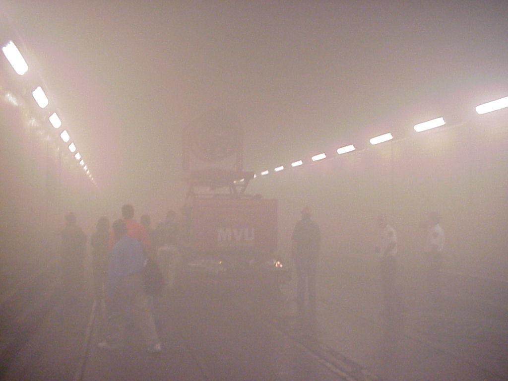
14 Leroy Coffman from Tempest Technology Corporation provided a one-half hour training session on the operation of the UUT. Due to performance of the UUT and the configuration of the ventilation within the tunnel, Test 3, PPV (Moving North), was conducted from a stationary point 100 feet inside the South Portal Entrance, instead of moving the UUT from the south to north end of the tunnel. This test change provided a better test of the unit s capabilities and produced a more realistic testing scenario. In order to provide a safer testing environment, smoke generators were used instead of smoke grenades. Two Tempest Technology Corporation smoke generators were started at the 1,400- foot marker inside the tunnel and ran for 10 minutes at the beginning of each test. This caused completely obscured visibility in the immediate area (a 200-foot wide cloud of smoke). Figure 3-1. Generating Smoke with Tempest Shadow 2 Smoke Generators All measurements recorded within this test report are south to north. Testing began at 10:00 and ended at 16:30. Test controllers were Mickey Kirschenbaum, Allison Voight, Brendon LaTurno, Howard Murphy, Forrest Church, and Dutch Thomas of SAIC. 3.1 Baseline Test Prior to the start of the test, smoke was generated from two smoke generators for 10 minutes. The doors at the North and South Portals were open during this test event. The smoke generators were run for 10 minutes at the 1,400-foot location inside the tunnel. When smoke generation ended, visibility at the 1,400-foot location was completely obscured. For the first 30 minutes of the test, the smoke oscillated somewhat; however, visibility did not markedly improve. After 30 minutes, the smoke began to slowly clear, and visibility improved towards 13
15 both the North and South Portals. Test controllers determined that emergency responders would have had sufficient visibility to perform their mission 30 minutes into the test event. After 52 minutes, test controllers determined that the smoke movement was stagnant. Testing began at 15:12 and ended at 16:04. Test controllers were Forrest Church and Dutch Thomas of SAIC Test Observations The natural airflow through the tunnel proved insufficient to clear the tunnel of smoke. At the start of the test, wind speed at the 1,400-foot mark registered at 0.81 miles per hour (MPH) from north to south. This test provided the test team with a basic understanding through observation of the airflow dynamics within the tunnel for that specific time. See Table 3-1 for test timeline. Time Event 15:12 Smoke generators starts at the 1,400 foot marker. Natural airflow is north to south. 15:22 Smoke generation ended. 15:24 Air speed was calm with no natural air movement. Smoke plume begins oscillating. 15:32 Smoke plume begins noticeable movement towards the south. 15:33 At the 1,400 foot marker, there is 10 ft. visibility with wind speed at 1.0 MPH (north to south and south to north). 15:59 Smoke moves to between feet from the South Portal entrance. Wind speed is 1.4 MPH (north to south) 16:00 South Portal entrance visible from the 1,000 foot marker. 16:04 End test. Table 3-1. Test 1 Timeline 3.2 PPV (South to North) Operational Testing The UUT was stationed outside the South Portal Entrance while two smoke generators were run for 10 minutes at the 1,400 foot marker inside the tunnel. When smoke generation ended, visibility at the 1,400 foot marker was completely obscured. Once the PPV began, wind speed and airflow from the South Portal increased above the control point (see Table 3-2) and the smoke began to move towards the North Portal. In less than 10 minutes, all smoke had moved past the 1,800 foot marker. After 13 minutes, the manufacturer s representative shut down the UUT. He had stated that from the operators vantage point, it had appeared that the smoke had stalled and was no longer moving. This was incorrect since the test observers were still recording movement. While the tunnel was not completely cleared of smoke, test controllers called end test since PPV was no longer in effect and the UUT would had to have been restarted. Distance Marker Control/Baseline PPV (South to North) 800 feet 1.5 MPH 2.0 MPH 1,400 feet 0.81 MPH - 2,200 feet 0.0 MPH - Table 3-2. Wind Speed Recordings Taken During Test 2 14
16 Testing began at 10:36 and ended at 11:02. Test controllers were Mickey Kirschenbaum, Allison Voight, Brendon LaTurno, Howard Murphy, Forrest Church and Dutch Thomas of SAIC Test Observations When end test was called, test controllers at the 1,400 foot marker noticed that the smoke had dissipated, but had not completely cleared the tunnel. It was determined that there was enough visibility at the 1,400-foot marker for emergency responders to perform their mission. Test controllers at the UUT did not observe test operators experiencing any difficulties operating the UUT. Test operators reported no difficulty in operating the UUT. The unit was not able to achieve optimal PPV due to the presence of multiple ventilation ports in the tunnel that allowed for air to escape from more than one point. See Table 3-3 for test timeline. Time Event 10:36:00 Smoke generators started at1,400 foot marker. Natural airflow is north to south. 10:46:00 Smoke generation ends. 10:49:37 MVU starts at South Portal entrance. PPV begins. 10:50:00 Smoke plume moves toward the North Portal entrance. 10:54:00 At 1,800-foot marker, visibility is feet in both directions. 10:56:00 Smoke plume reaches 2,800-foot marker. 10:58:00 At 1,800-foot marker, visibility is 50 feet in both directions. 11:00:45 At 1,400-foot marker, visibility is 200 feet to the south. 11:01:30 At 1,800-foot marker, visibility is 200 feet to the north. 11:02:11 MVU shut-down by manufacturer. Table 3-3. Test 2 Timeline 3.3 PPV (North to South) Operational Testing The UUT was stationed 40 feet outside the North Portal Entrance. Two smoke generators were run for 10 minutes at the beginning of the test exercise at the 1,400 foot marker. When the smoke generation ended, visibility at the 1,400 foot marker was completely obscured. Upon initiation of PPV, wind speed at the 2,200-foot marker increased to 2.53 MPH. Within 10 minutes, a majority of the smoke had moved to the South Portal Entrance of the tunnel. After 23 minutes, test controllers determined that the tunnel was clear of smoke and end test was called. Testing began at 13:58 and ended at 14:22. Test controllers were Mickey Kirschenbaum, Allison Voight, Brendon LaTurno, Howard Murphy, Forrest Church and Dutch Thomas of SAIC Test Observations The performance of the UUT in this test exercise showed marked improvement over previous test exercises from the southern portion of the tunnel, due to the ability to seal the northern portal of the tunnel enabling PPV. Due to logistics, this test was performed after tests 2 and 4. Test controllers at the UUT did not observe test operators experiencing any difficulties operating the UUT. Test operators reported that they had no difficulty operating the UUT and the UUT was operated until the tunnel was clear of smoke (23 minutes). The obstructions in the tunnel 15
17 (trailers, vehicles, small buildings, etc.) did not appear to significantly affect the performance of the UUT. See Table 3-4 for test timeline. Time Event 13:58:17 Smoke generators starts at1,400 foot marker. Natural airflow is north to south. 14:08:17 Smoke generation ends. 14:08:26 MVU starts at North Portal entrance. PPV begins. 14:08:30 At the 2,700 foot marker, clear visibility. 14:09:00 Smoke plume reaches 1,800 foot marker. 14:09:10 At the 2,600 foot marker, clear visibility. 14:09:20 At the 1,800 foot marker, 15 foot visibility. 14:09:30 At the 2,500 foot marker, clear visibility. 14:10:00 At the 2,400 foot marker, clear visibility. 14:10:10 At the 1,800 foot marker, 3 foot visibility with a wind speed of 4.4 MPH. 14:10:30 At the 2,100 foot marker, clear visibility. 14:11:00 At the 2,000 foot marker, clear visibility. The smoke is traveling swiftly. 14:11:15 At the 1,800 foot marker, 10 foot visibility with a wind speed of 4.4 MPH. 14:11:30 At the 1,700 foot marker, clear visibility. 14:12:00 At the 1,800 foot marker, 20 foot visibility with a wind speed of 4.4 MPH. 14:12:10 At the 1,500 foot marker, clear visibility. The smoke is traveling slowly. 14:13:00 At the 1,800 foot marker, 30 foot visibility with a wind speed of 4.4 MPH. 14:14:00 At the 1,800 foot marker, 75 foot visibility with a wind speed of 3.6 MPH. 14:14:22 At the 1,200 foot marker, clear visibility. The smoke is density decreasing. 14:15:00 At the 1,800 foot maker, 200 foot visibility with a speed of 3.4 MPH. 14:16:00 At the 1,800 foot maker, 400 foot visibility with a wind speed of 3.6 MPH. 14:16:10 At the 1,800 foot maker, clear visibility. The smoke layering and density is no longer changing. 14:17:00 At the 1,800 foot maker, 600 foot visibility with a wind speed of 3.5 MPH. 14:17:44 At the 800 foot maker, clear visibility. The smoke layering and density is no longer changing. 14:18:00 At the 1,800 foot maker, 600 foot visibility with a wind speed of 3.2 MPH. Table 3-4. Test 3 Timeline 16
18 Time Event 14:19:00 Upper half of South Portal entrance visible from the 700 foot marker. 14:19:10 At the 1,800 foot maker, 1000 foot visibility with a wind speed of 3.5 MPH. South Portal entrance is visible. 14:21:00 At the 400 foot marker, clear visibility. The remaining smoke is not dense enough to impeded emergency operations. 14:21:56 End test and MVU shut-down. Table 3-4. Test 3 Timeline (continued) 3.4 PPV (South moving North) Operational Testing Prior to testing, test operators, test controllers, and the manufacturer s representatives determined that leaving the unit stationary instead of moving it north would provide a better test of the UUT and a more realistic testing scenario. The UUT was stationed 100 feet inside the South Portal Entrance. Two smoke generators were run for 10 minutes at the beginning of the test exercise at the 1,400 foot marker. When the smoke generation ended, visibility at the 1,400 foot marker was completely obscured. Upon initiation of PPV, the smoke began to move towards the North Portal. Within 10 minutes, a majority of the tunnel was clear of smoke, the exception being at the northernmost end of the tunnel. After 25 minutes, the tunnel was clear of smoke and UUT operations were terminated. See Table 3-5 for wind speed measurements. Distance Marker Control/Baseline PPV (South to North) 800 feet 1.5 MPH 1.5 MPH 1400 feet 0.81 MPH 1.61 MPH 2200 feet 0.0 MPH 1.5 MPH Table 3-5. Wind Speed Measurements During PPV (South moving North) Test Testing began at 11:22 and ended at 12:00. Test controllers were Mickey Kirschenbaum, Allison Voight, Brendon LaTurno, Howard Murphy, Forrest Church, and Dutch Thomas of SAIC Test Observations The UUT s performance improved markedly in this test over its performance in Test 2 because it was moved past the additional ventilation ports. However, it was unable to achieve PPV due to the inability to seal the tunnel entrance during MVU operations in this series of tests. Most of the air was forced out of the north end of the tunnel; however, it appeared that some of the air was caught in a vortex above the unit, and air was still escaping through the additional ventilation at the south end of the tunnel. Test controllers positioned at the UUT did not observe test operators experiencing any difficulties operating the UUT. Test operators reported that they had no difficulty operating the UUT and the UUT was operated until the tunnel was clear of smoke. The obstructions in the tunnel (trailers, vehicles, small buildings, etc.) did not appear to significantly affect the performance of the UUT. See Table 3-6 for test timeline. 17
19 Time Event 11:22:45 Smoke generators start at1,400 foot marker. Natural airflow is north to south. 11:32:45 Smoke generation ends. 11:33:40 MVU starts at North Portal entrance. PPV begins. 11:34:22 At 1,800 foot marker, smoke movement observed. 11:34:30 At 1,800 foot marker, 400 foot visibility. 11:35:00 At 300 foot marker, zero visibility. 11:35:30 At 1,800 foot marker, 200 foot visibility. 11:36:00 At 1,800 foot marker, 100 foot visibility 11:36:30 At 500 foot marker, 5 foot visibility. 11:37:00 At 600 foot marker, 5-6 foot visibility. 11:37:30 At 1,800 foot marker, 20 foot visibility. 11:37:15 Smoke plume reaches 1,800 foot marker. 11:38:00 At 700 foot marker, 6 foot visibility. 11:38:30 At 1,800 foot marker, 10 foot visibility. 11:39:00 At 1,800 foot marker, 5 foot visibility. 11:39:30 At 800 foot marker, 20 foot visibility. 11:40:00 At 800 foot marker, South Portal visible and 40 foot visibility to the north. 11:40:30 At 1,800 foot marker, 5 foot visibility. 11:41:00 At 900 foot marker, 50 foot visibility. Smoke estimated to be 50% dissipated. 11:41:30 At 1,800 foot marker, 15 foot visibility. 11:42:00 At 1,000 foot marker, smoke moving at a walking pace. 11:42:15 At 1,800 foot marker, 50 foot visibility. 11:42:30 At 1,100 foot marker, good visibility. 11:43:00 At 1,800 foot marker, 75 foot visibility. 11:43:35 At 1,400 foot marker, 125 foot visibility. Smoke is evenly distributed as a haze like atmosphere and no impediment to use of equipment with ambient light. 11:44:00 At 1,800 foot marker, 100 foot visibility. 11:45:00 At 1,800 foot marker, 100 foot visibility. 11:46:00 At 1,800 foot marker, 150 foot visibility. 11:47:00 At 1,800 foot marker, 150 foot visibility. 11:48:00 At 1,800 foot marker, 200 foot visibility. North Portal can be seen. 11:56:51 Smoke clear of North portal and entire tunnel is clear. 12:01:30 End test and MVU shut-down. Table 3-6. Test 4 Timeline 3.5 Decontamination of Personnel Utilizing UUT and Misting Ring Prior to testing, three test subjects were dressed in various configurations (Level A personal protective equipment (PPE), Level B PPE, and a flight suit) and sprayed with a florescent glow- 18

20 in-the-dark spray, used as the simulated contaminant for the decontamination test exercises. The UUT was stationed outside the South Portal Entrance. A standard 2 ½-inch doublejacketed fire hose was attached to the UUT from the facilities water pump. The pump at the facility provides water at a rate of up to 80 pounds per minute. The UUT, configured with a Tempest Misting Ring and water, with no additives, was used to decontaminate three individuals in various levels of protective or standard clothing. The individuals proceeded from the South Portal Entrance to the decontamination area, which was directly outside the tunnel entrance (see Figure 3-2). While in the decontamination area, the test participants rotated their stationary positions under the MVU Misting Ring water decontamination for 2 minutes before exiting the decontamination area. After 5 minutes, the UUT was shut down and end test was called. The test subjects were examined with an ultraviolet light in order to detect the florescent spray. Figure 3-2. Decontamination of Personnel utilizing UUT and Misting Ring Testing began at 15:25 and ended at 15:30. Test controllers were Mickey Kirschenbaum, Allison Voight, Brendon LaTurno, and Howard Murphy of SAIC Test Observations Test controllers observed that there were slight traces of the simulated contaminant remaining under the arms and on the backs of the test participants in Level A and Level B PPE. Test controllers determined that this was due to test participants not adequately exposing those areas of the PPE to the decontaminant. Test controllers detected traces of the simulated contaminant on the NOMEX flight suit worn by the third test participant. It appeared that the flight suit material had absorbed some of the simulated contaminant, though the bulk of it had been removed during the decontamination process. It was determined that the UUT performed adequately as a means of personnel expedient or gross decontamination. The UUT was 19

21 capable of removing the majority of the contamination from the PPE without the use of additional decontamination equipment (e.g., brushes, additives). Test controllers did not observe any difficulties operating the device and test operators reported no difficulty operating the UUT. 3.6 Decontamination of Vehicles Utilizing UUT and Misting Ring Prior to testing, one vehicle (large sport utility vehicle) was sprayed along its passenger side with a simulated contaminant and parked at the South Portal Entrance. The UUT was stationed outside the South Portal Entrance (see Figure 3-3). The vehicle underwent 4 minutes of MVU Misting Ring generated decontamination using water with no additives. After 4 minutes, the UUT was shut down and end test was called. Figure 3-3. Decontamination of SUV with MVU with Misting Ring Testing began at 15:38 and ended at 15:42. Test controllers were Mickey Kirschenbaum, Allison Voight, Brendon LaTurno, and Howard Murphy of SAIC Test Observations Test controllers detected trace amounts of the simulated contaminant without the aid of the black light. When using a black light, significant amounts of simulated contaminant was found concentrated in places where vehicle body panels and windows met. Most open surfaces were free from the simulated contaminant. It was determined that the unit performed less than adequately as a means of expedient or gross decontamination by itself and that the use of additional decontamination equipment (e.g., brushes, additives) would be necessary to remove the simulated contaminant from the vehicle s exterior. Test controllers did not observe any difficulties operating the device. Test operators reported no difficulty operating the UUT. 20
22 4.0 Conclusions 4.1 Analysis of System s Capabilities and Limitations Capabilities The operational test and evaluation revealed the following UUT capabilities: There is a limited training period required prior to operation of the UUT. Operational proficiency in most aspects of the operation of the UUT can be gained with a one-half hour training session. The manufacturer s representative did assist in the operation of the UUT for some testing. The UUT is optimal for moving large quantities of air in a tunnel environment. The fan on the UUT is easily maneuverable. The controls on the MVU allow the operator to adjust the fan from left to right and up and down, to place it in the desired position. The UUT performed adequately as a means of personnel expedient or gross decontamination Limitations The operational test and evaluation revealed the following UUT limitations: The UUT is not as effective when there are multiple ventilation exits from which air can escape. The UUT is difficult to position on the trailer. It was determined that the UUT performed less than adequately as a means of expedient or gross decontamination of vehicles. 4.2 Lessons Learned Based on observations, the data collected, and UUT operator feedback, the following are lesson learned from this Test Series: If possible, seal off any additional ventilation, leaving only one exit through which smoke and contaminated air can exit. 4.3 Suggested Refinements Based on observations, the data collected, and UUT operator feedback, the CNR Operational Test and Evaluation Program recommends the following refinements: Installing an alarm/safety switch that notifies the operator when the carriage is at rest. This would prevent the MVU from being transported in an unsafe manner. During testing, the MVU was transported while the carriage was not fully rested. Use a joystick, instead of switches, to position the fan. This would allow the operator to position the fan without the restriction of looking at the controls. Reconfigure the location of the control panel. In its current location, the heat from the radiator blows directly on the operator. Add a water pressure gage for use with the Misting Ring. This would allow operators to determine the water pressure going into the MVU. 21
23 Appendices 22
24 C E N T E R F O R N A T I O N A L R E S P O N S E - O P E R A T I O N A L T E S T A N D E V A L U A T I O N P R O G R A M Appendix A - Test Data Sheets Test Data Sheet Test Series: CNR Test Organization: 130 th WVANG FD Test Procedure Number: 1 Test Name: Baseline Test Test Location: CNR, Standard, WV Test Start Point: 1400 foot mark Date: 27 June 2002 Test Time (Start End): 15:12-16:04 Test Controller Name: Forrest Church and Dutch Thomas Operator(s) Name(s): N/A Environmental Conditions Light: 118 Lux Temperature: 70 Precipitation: None Humidity: High Comments See Table 3-1 in Section 3.1 for a detailed test timeline. 23
25 C E N T E R F O R N A T I O N A L R E S P O N S E - O P E R A T I O N A L T E S T A N D E V A L U A T I O N P R O G R A M Test Data Sheet for Test 1 Step # Observer Action Y N Not Observed Comments 1 Determine wind speed and direction of natural air movement in the tunnel. - Record all Wind speed was 0.81 MPH from the north. 2 Detonate a M18 smoke grenade at the 1,400- foot marker. - Not observable. 3 Determine visual acuity at 1,400-foot marker and 2,800-foot marker (North Portal Entrance) and (2) wind speed at 700-foot marker, 1,400-foot marker, 2,100-foot marker, and 2,800-foot marker (North Portal Entrance). - Record all 4 Using visual acuity at 1,400-foot marker and 2,800-foot marker, determine when tunnel is clear of all smoke. - Record elapsed time and all 5 End Test. - No observations. Smoke generators were used instead of a M18 grenade. Smoke oscillated with no appreciable improvement. End Test was called at 52 minutes; last remaining smoke had ceased to dissipate. Visibility was adequate for emergency operations. OK. 24
26 C E N T E R F O R N A T I O N A L R E S P O N S E - O P E R A T I O N A L T E S T A N D E V A L U A T I O N P R O G R A M Test Data Sheet Test Series: CNR Test Organization: 130 th WVANG FD Test Procedure Number: 2 Test Name: PPV (South to North) Operational Testing Test Location: CNR, Standard, WV Test Start Point: Outside South portal Date: 27 June 2002 Test Time (Start End): Test Controller Name: Mickey Kirschenbaum, Allison Voight, Brendon LaTurno, Howard Murphy, Forrest Church and Dutch Thomas Operator(s) Name(s): SSgt Olaf Funfstuck II and SSgt William Allen Gannon Environmental Conditions Light: 118 Lux Temperature: 70 Precipitation: None Humidity: High Comments See Tables 3-2 and 3-3 in Section 3.2 for detailed wind speed recordings and test timeline. 25
27 C E N T E R F O R N A T I O N A L R E S P O N S E - O P E R A T I O N A L T E S T A N D E V A L U A T I O N P R O G R A M Test Data Sheet for Test 2 Step # Observer Action Y N Not Observed Comments 1 Operator 1 conducts situational assessment of incident site. - Observe operator actions and record all OK. 2 Operators position UUT 75 feet from South Portal Entrance. - Observe operator actions and record all 3 Operators power up UUT and conduct baseline check of all systems functions. - Observe operator actions and record all 4 Initiate PPV. - Observe operator actions. Record: (1) visual acuity at 1,400 foot marker and 2,800 foot marker (North Portal Entrance) and (2) wind speed at 700 foot marker, 1,400 foot marker, 2,100 foot marker, and 2,800 foot marker (North Portal Entrance). 5 UUT operates until tunnel is clear of all smoke. - Observe operator actions and record time until smoke has cleared the tunnel. 6 Operator 1 conducts situational assessment of incident site. - Observe and record all UUT was located 40 feet from entrance. OK. See Tables 3-1 and 3-2 in section 3.2. UUT was shut down prior to total clearing. Test operators were given poor information on progress of the smoke. OK. 26
28 C E N T E R F O R N A T I O N A L R E S P O N S E - O P E R A T I O N A L T E S T A N D E V A L U A T I O N P R O G R A M Test Data Sheet for Test 2 Step # Observer Action Y N Not Observed Comments 7 Power down UUT and conduct baseline check of all systems functions. - Observe operator actions and record all OK. 8 End Test. - No observations. OK. 27
29 C E N T E R F O R N A T I O N A L R E S P O N S E - O P E R A T I O N A L T E S T A N D E V A L U A T I O N P R O G R A M Test Data Sheet Test Series: CNR Test Organization: 130 th WVANG FD Test Procedure Number: 3 Test Name: PPV (North to South) Operational Testing Test Location: CNR, Standard, WV Test Start Point: Outside North portal entrance Date: 27 June 2002 Test Time (Start End): 13:58-14:22 Test Controller Name: Mickey Kirschenbaum, Allison Voight, Brendon LaTurno, Howard Murphy, Forrest Church and Dutch Thomas Operator(s) Name(s): SSgt Olaf Funfstuck II and SSgt William Allen Gannon Environmental Conditions Light: 118 Lux Temperature: 70 Precipitation: Mist Humidity: High Comments See Table 3-4 in Section 3.3 for a detailed test timeline. 28
30 C E N T E R F O R N A T I O N A L R E S P O N S E - O P E R A T I O N A L T E S T A N D E V A L U A T I O N P R O G R A M Test Data Sheet for Test 3 Step # Observer Action Y N Not Observed Comments 1 Operator 1 conducts situational assessment of incident site. - Observe operator actions and record all OK. 2 Operators position UUT 75 feet from North Portal Entrance. - Observe operator actions and record all 3 Operators power up UUT and conduct baseline check of all systems functions. - Observe operator actions and record all 4 Initiate PPV. - Observe operator actions. Record: (1) visual acuity at 1,400-foot marker and 2,800-foot marker (North Portal Entrance) and (2) wind speed at 700-foot marker, 1,400-foot marker, 2,100-foot marker, and 2,800-foot marker (North Portal Entrance). 5 UUT operates until tunnel is clear of all smoke. - Observe operator actions and record time until smoke has cleared the tunnel. 6 Operator 1 conducts situational assessment of incident site. - Observe and record all UUT was located 40 feet from entrance. OK. See Tables 3-3 in section 3.4. See tables 3-3 in section 3.4. OK. 29
31 C E N T E R F O R N A T I O N A L R E S P O N S E - O P E R A T I O N A L T E S T A N D E V A L U A T I O N P R O G R A M Test Data Sheet for Test 3 Step # Observer Action Y N Not Observed Comments 7 Power down UUT and conduct baseline check of all systems functions. - Observe operator actions and record all OK. 8 End Test. - No observations. OK. 30
32 C E N T E R F O R N A T I O N A L R E S P O N S E - O P E R A T I O N A L T E S T A N D E V A L U A T I O N P R O G R A M Test Data Sheet Test Series: CNR Test Organization: 130 th WVANG FD Test Procedure Number: 4 Test Name: PPV (Moving North) Operational Testing Test Location: CNR, Standard, WV Test Start Point: 100 feet inside South portal entrance Date: 27 June 2002 Test Time (Start End): 11:22-12:01 Test Controller Name: Mickey Kirschenbaum, Allison Voight, Brendon LaTurno, Howard Murphy, Forrest Church and Dutch Thomas Operator(s) Name(s): SSgt Olaf Funfstuck II and SSgt William Allen Gannon Environmental Conditions Light: 118 Lux Temperature: 70 Precipitation: None Humidity: High Comments Prior to testing, test operators, test controllers, and the manufacturer s representatives determined that leaving the unit stationary instead of moving it north would provide a better test of the UUT and a more realistic testing scenario. See Tables 3-5 and 3-6 in Section 3.4 for detailed test timelines. 31
33 C E N T E R F O R N A T I O N A L R E S P O N S E - O P E R A T I O N A L T E S T A N D E V A L U A T I O N P R O G R A M Test Data Sheet for Test 4 Step # Observer Action Y N Not Observed Comments 1 Operator 1 conducts situational assessment of incident site. - Observe operator actions and record all OK. 2 Operators position UUT at South Portal Entrance. - Observe operators actions and record all 3 Operators power up UUT and conduct baseline check of all systems functions. - Observe operators actions and record all 4 Initiate PPV. - Observe operator actions and record wind speed at 1,400-foot marker. 5 Move UUT to 100-foot marker. - Observe and record wind speed at 1,400- foot marker. 6 Move UUT to 200-foot marker. - Observe and record wind speed at 1,400- foot marker. 7 Move UUT to 300-foot marker. - Observe and record wind speed at 1,400- foot marker. OK. No difficulty observed. OK. Optimal PPV was not attainable. UUT was started at 100-foot marker. UUT remained at 100-foot marker for the duration of the test. This change was determined prior to testing. UUT remained at 100-foot marker for the duration of the test. This change was determined prior to testing. 32
34 C E N T E R F O R N A T I O N A L R E S P O N S E - O P E R A T I O N A L T E S T A N D E V A L U A T I O N P R O G R A M Test Data Sheet for Test 4 Step # Observer Action Y N Not Observed Comments 8 Move UUT to 400-foot marker. - Observe and record (1) wind speed at 1,400 foot marker and (2) visual acuity at 2,800 foot marker (North Portal Entrance). UUT remained at 100-foot marker for the duration of the test. This change was determined prior to testing. 9 Move UUT to 500-foot marker. - Observe and record (1) wind speed at 1,400 foot marker and (2) visual acuity at 2,800 foot marker (North Portal Entrance). 10 Move UUT to 600-foot marker. - Observe and record (1) wind speed at 1,400 foot marker and (2) visual acuity at 2,800 foot marker (North Portal Entrance). 11 Move UUT to 700-foot marker. - Observe and record (1) wind speed at 1,400 foot marker and (2) visual acuity at 2,800 foot marker (North Portal Entrance). 12 UUT operates until tunnel is clear of all smoke. - Observe operator actions and record time until smoke has cleared the tunnel. 13 Operator 1 conducts situational assessment of incident site. - Observe and record all 14 Power down UUT and conduct baseline check of all systems functions. - Observe operator actions and record all UUT remained at 100-foot marker for the duration of the test. This change was determined prior to testing. UUT remained at 100-foot marker for the duration of the test. This change was determined prior to testing. UUT remained at 100-foot marker for the duration of the test. This change was determined prior to testing. See Table 3.6 in section Ok. OK. 33
35 C E N T E R F O R N A T I O N A L R E S P O N S E - O P E R A T I O N A L T E S T A N D E V A L U A T I O N P R O G R A M Test Data Sheet for Test 4 Step # Observer Action Y N Not Observed Comments 15 End Test. - No observations OK. 34
36 C E N T E R F O R N A T I O N A L R E S P O N S E - O P E R A T I O N A L T E S T A N D E V A L U A T I O N P R O G R A M Test Data Sheet Test Series: CNR Test Organization: 130 th WVANG FD Test Procedure Number: 5 Test Name: Decontamination of Personnel Utilizing UUT and Misting Ring Test Location: CNR, Standard, WV Test Start Point: Outside South portal entrance Date: 27 June 2002 Test Time (Start End): 15:25-15:30 Test Controller Name: Mickey Kirschenbaum, Allison Voight, Brendon LaTurno and Howard Murphy Operator(s) Name(s): SSgt Olaf Funfstuck II and SSgt William Allen Gannon Environmental Conditions Light: Outside, Sunny Temperature: 72 Precipitation: None Humidity: High Comments 35
37 C E N T E R F O R N A T I O N A L R E S P O N S E - O P E R A T I O N A L T E S T A N D E V A L U A T I O N P R O G R A M Test Data Sheet for Test 5 Step # Observer Action Y N Not Observed Comments 1 Test Subjects are sprayed with florescent material. - Using black light, photograph sprayed areas. Used Clue Spray. 2 Operators establish a decontamination area at the South Portal Entrance. - Observe operator actions and record all 3 Operators position UUT with Misting Ring 75 feet from South Portal Entrance. - Observe operator actions and record all 4 Operators power up UUT and conduct baseline check of all systems functions. - Observe operator actions and record all 5 Initiate PPV with misting ring. - Observe operator actions. Record wind speed at 100, 150, and 200 feet from UUT and all Decontamination area was cleared prior to testing. OK. OK. Wind speeds in water-stream was approximately 10 MPH. 36
38 C E N T E R F O R N A T I O N A L R E S P O N S E - O P E R A T I O N A L T E S T A N D E V A L U A T I O N P R O G R A M Test Data Sheet for Test 5 Step # Observer Action Y N Not Observed Comments 6 Test Subject 1, positioned at the 500 foot marker, and Test Subject 2, positioned at the 1,000 foot marker walk toward the decontamination area at a normal pace. - Observe test subjects actions. Upon exiting the tunnel, record: (1) total time, (2) amount of moister on clothing, (3) areas of the body that were not affected by the UUT, and (4) physical condition of the test subjects. Test subject walked from South Portal Entrance to decon area outside the tunnel. Water pressure prevented the subject from walking at a normal pace. 7 Using black light, check test subjects to determine if they were properly decontaminated. - Photograph sprayed areas and record all 8 Power down UUT and conduct baseline check of all systems functions. - Observe operator actions and record all 9 End Test. - No observations Residual florescent was seen on the flight suit, under the arms, and on the backs of the test subjects in the Level A and B PPE. OK. OK. 37
39 C E N T E R F O R N A T I O N A L R E S P O N S E - O P E R A T I O N A L T E S T A N D E V A L U A T I O N P R O G R A M Test Data Sheet Test Series: CNR Test Organization: 130 th WVANG FD Test Procedure Number: 6 Test Name: Decontamination of Vehicles Utilizing UUT and Misting Ring Test Location: CNR, Standard, WV Test Start Point: Outside South portal entrance Date: 27 June 2002 Test Time (Start End): Test Controller Name: Mickey Kirschenbaum, Allison Voight, Brendon LaTurno and Howard Murphy Operator(s) Name(s): SSgt Olaf Funfstuck II and SSgt William Allen Gannon Environmental Conditions Light: Outside, Sunny Temperature: 72 Precipitation: None Humidity: High Comments 38
40 C E N T E R F O R N A T I O N A L R E S P O N S E - O P E R A T I O N A L T E S T A N D E V A L U A T I O N P R O G R A M Test Data Sheet for Test 6 Step # Observer Action Y N Not Observed Comments 1 Vehicles are sprayed with florescent material. - Using black light, photograph sprayed areas. A large SUV s passenger side was sprayed with Clue Spray. 2 Operators position UUT with Misting Ring 75 feet from test vehicles. - Observe operator actions and record all 3 Operators power up UUT and conduct baseline check of all systems functions. - Observe operator actions and record all 4 Initiate PPV with Misting Ring for 5 minutes. - Observe operator actions. Record wind speed at 100, 150, and 200 feet from UUT and all 5 Cease PPV with Misting Ring. - Observe operator actions and record all 6 Using black light, check sprayed areas of vehicles. - Photograph sprayed areas and record all 7 If vehicles were not completely decontaminated, initiate PPV with misting ring for an additional 5 minutes. - Observe operator actions and record all result. OK. Testing was conducted outside the South Portal Entrance. OK. Due to limited water supply, PPV was only initiated for 4 minutes. OK. Trace amounts of the simulated contaminant were detected without the aid of the black light, and, with the assistance of the black light, significant amounts of simulated contaminant concentrated in places where vehicle body panels and windows met. Decontamination was not continued due to limited water supply. 39
41 C E N T E R F O R N A T I O N A L R E S P O N S E - O P E R A T I O N A L T E S T A N D E V A L U A T I O N P R O G R A M Test Data Sheet for Test 6 Step # Observer Action Y N Not Observed Comments 8 Cease PPV with misting ring. - Observe operator actions and record all Decontamination was not continued due to limited water supply. 9 Using black light, check sprayed areas of vehicles. - Photograph sprayed areas and record all 10 If vehicles were not completely decontaminated, initiate PPV with misting ring for an additional 5 minutes. - Observe operator actions and record all result. See Step 6. Decontamination was not continued due to limited water supply. 11 Cease PPV with misting ring. - Observe operator actions and record all Decontamination was not continued due to limited water supply. 12 Using black light, check sprayed areas of vehicles. - Photograph sprayed areas and record all 13 If vehicles were not completely decontaminated, initiate PPV with Misting Ring for an additional 5 minutes. - Observe operator actions and record all result. See Step 6. Decontamination was not continued due to limited water supply. 14 Cease PPV with Misting Ring. - Observe operator actions and record all Decontamination was not continued due to limited water supply. 40
42 C E N T E R F O R N A T I O N A L R E S P O N S E - O P E R A T I O N A L T E S T A N D E V A L U A T I O N P R O G R A M Test Data Sheet for Test 6 Step # Observer Action Y N Not Observed Comments 15 Using black light, check sprayed areas of vehicles. - Photograph sprayed areas and record all See Step End test. - No observations OK. 41


43 Appendix B - Test Photos 42


44 43

45 44
APPLCATIONS OF POSITIVE PRESSURE VENTILATION DURING AIRPORT AND ARFF INCIDENTS. Leroy B. Coffman III, Tempest Technology Corporation, USA
 APPLCATIONS OF POSITIVE PRESSURE VENTILATION DURING AIRPORT AND ARFF INCIDENTS Leroy B. Coffman III, Tempest Technology Corporation, USA ABSTRACT Positive Pressure Ventilation (PPV) is the use of high-powered
Guidelines for Rapid Extraction in a Hazardous Materials Environment
 Guidelines for Rapid Extraction in a Hazardous Materials Environment A hazardous materials incident with victims who have been exposed to a contaminant and are unable to remove themselves from the affected
Permit-Required Confined Spaces...29CFR
 (Compliance Audit) Section (c) General Requirements 1) Has the employer performed a workplace inspection to determine if there are Yes No NA permit-required confined spaces (PRCS) present? 2) If the workplace
EUSCS04 Overseeing work in confined spaces
 Overview This unit is about the duties of a safety attendant (top-man/woman) which does not require entries into confined spaces. It is about controlling the pre-entry procedures and entry into and out
CONFINED SPACE ENTRY
 CONFINED SPACE ENTRY Background On May 4, 2015, OSHA issued a new standard for construction work in confined spaces The rule became effective on August 3, 2015 29 CFT 1926 Subpart AA Prior to the rule
OBJECTIVE 22: EMERGENCY WORKERS, EQUIPMENT, AND VEHICLES - MONITORING AND DECONTAMINATION
 OBJECTIVE Demonstrate the adequacy of procedures for the monitoring and decontamination of emergency workers, equipment, and vehicles. INTENT This objective is derived from NUREG-0654 which provides that
SITUATIONAL AWARENESS, DISORIENTATION and IMPROVING FIREFIGHTER SURVIVAL AT STRUCTURAL FIRES
 SITUATIONAL AWARENESS, DISORIENTATION and IMPROVING FIREFIGHTER SURVIVAL AT STRUCTURAL FIRES LT. MIKE MASON Within the modern day fire service at structural fires firefighters are faced with an ever changing
CHESTERFIELD COUNTY FIRE AND EMERGENCY MEDICAL SERVICES PROCEDURES
 CHESTERFIELD COUNTY FIRE AND EMERGENCY MEDICAL SERVICES PROCEDURES Division: Emergency Operations Procedure: Emergency Operations #24 Subject: Toxic Exposure Reduction Supersedes: Authorized by: Deputy
HAZ MAT RESPONSE SOG
 SCOPE HAZ MAT RESPONSE SOG This guideline shall apply to all members of the Stoney Point Fire Department and shall be adhered to by all members. PURPOSE This guideline is specifically applicable to known
Unit 3.3 Personal Protective Equipment (Core)
") INSTRUCTOR GUIDE Unit 3.3 Personal Protective Equipment (Core) INSTRUCTOR GUIDE TERMINAL OBJECTIVE Given incident scenarios, the participant will be able to identify the basic PPE requirements for operations
INSTRUCTOR GUIDE Unit 3.3 Personal Protective Equipment (Core) INSTRUCTOR GUIDE TERMINAL OBJECTIVE Given incident scenarios, the participant will be able to identify the basic PPE requirements for operations
Storage and Pre-planning Considerations
 Participant Guide Module 8 Storage and Pre-planning Considerations Module Objective Upon the completion of this module, participants should be able to develop plans to fight or contain fires at tank farms
CONFINED SPACE WRITTEN PROGRAM
 CONFINED SPACE WRITTEN PROGRAM Maple River Public Schools ISD#2135 Confined Space Entry Plan (Permit Required) Maple River Public School Plan last updated: October, 2014 Authority and Scope Regulation:
Mobile Breathing Air Systems
 FAMA BUYER S GUIDE TC053 Prepared by the FAMA Body Subcommittee This guide does not endorse any manufacturer or product Page 1 of 14 Contents Introduction... 3 Overview... 4 Mobile Breathing Air System
AIRFLOW GENERATION IN A TUNNEL USING A SACCARDO VENTILATION SYSTEM AGAINST THE BUOYANCY EFFECT PRODUCED BY A FIRE
 - 247 - AIRFLOW GENERATION IN A TUNNEL USING A SACCARDO VENTILATION SYSTEM AGAINST THE BUOYANCY EFFECT PRODUCED BY A FIRE J D Castro a, C W Pope a and R D Matthews b a Mott MacDonald Ltd, St Anne House,
Wilson County Emergency Management Agency 110 Oak Street Lebanon, Tennessee 37087
 SOG Name: One and Two Family Dwellings SOG Number: 403.18 Effective Date: February 2, 2015 Approved: Joey Cooper, Director Reviewed: Scope This procedure will provide an organized method in which to carry
Confined Space in Construction
 Confined Space in Construction 1926.1201 1926.1213 Confined space means a space that: 1. Is large enough and so configured that an employee can bodily enter it; 2. Has limited or restricted means for entry
An Overview of Confined Space Rescue Course Objectives
 An Overview of Confined Space Rescue 1 Course Objectives Provide the attendee with the basic understanding of the requirements of Confined Space Rescue so that the attendee can go to the next step of becoming
Course Objectives. An Overview of Confined Space Rescue
 An Overview of Confined Space Rescue 1 Course Objectives Provide the attendee with the basic understanding of the requirements of Confined Space Rescue so that the attendee can go to the next step of becoming
THE TLC COMPANIES. Self Inspection Program. Self Inspection. Program. Revised 12/13/2002 DC00026
 THE TLC COMPANIES Self Inspection Program Self Inspection Program Table of Contents SECTION 1 INSPECTION REQUIREMENTS 1 Informal Inspection 1 General Inspection 1 SECTION 3 CONDUCTING INSPECTIONS 5 Preparation
Using SolidWorks & CFD to Create The Next Generation Airlocks
 Using SolidWorks & CFD to Create The Next Generation Airlocks Matthew Gaffney Mechanical Engineer Geo-Centers, INC US Army Natick Soldier Center Natick, MA 01760 508-233-5557 Matthew.gaffney@natick.army.mil
SUBJECT: RAPID INTERVENTION CREW (RIC) SOG DATE ADOPTED: OCTOBER 18, 2012 REVISED: PAGES: 7
 SOG DATE ADOPTED: OCTOBER 18, 2012 REVISED: PAGES: 7") JOINT RESPONSE AGREEMENT MODEL STANDARD OPERATING GUIDELINE SUBJECT: RAPID INTERVENTION CREW (RIC) SOG DATE ADOPTED: OCTOBER 18, 2012 REVISED: PAGES: 7 SCOPE and PURPOSE Butler County firefighters often
JOINT RESPONSE AGREEMENT MODEL STANDARD OPERATING GUIDELINE SUBJECT: RAPID INTERVENTION CREW (RIC) SOG DATE ADOPTED: OCTOBER 18, 2012 REVISED: PAGES: 7 SCOPE and PURPOSE Butler County firefighters often
Leak Checking Large Vacuum Chambers
 Leak Checking Large Vacuum Chambers Technical Overview Vacuum Technologies Introduction Understanding the pump-down characteristics of a large vacuum vessel is critical for determining whether the vacuum
Committee Input No. 35-NFPA [ Chapter 1 ] Submitter Information Verification. Committee Statement
![Committee Input No. 35-NFPA [ Chapter 1 ] Submitter Information Verification. Committee Statement](/thumbs/89/99590399.jpg "Committee Input No. 35-NFPA [ Chapter 1 ] Submitter Information Verification. Committee Statement") Committee Input No. 35-NFPA 1670-2015 [ Chapter 1 ] Chapter 1 Administration 1.1 Scope. 1.1.1* This standard shall identify and establish levels of functional capability for conducting operations at technical
Committee Input No. 35-NFPA 1670-2015 [ Chapter 1 ] Chapter 1 Administration 1.1 Scope. 1.1.1* This standard shall identify and establish levels of functional capability for conducting operations at technical
Key Technology, Inc. Confined Space Entry Program. July, 2017
 Key Technology, Inc. Confined Space Entry Program July, 2017 Page 1 of 11 Key Technology, Inc. CONFINED SPACE ENTRY PROGRAM OVERVIEW Purpose: The purpose of this program is to ensure the protection of
Scope: This plan applies to all personnel, including contractors, who enter or work in confined spaces, or supervise such activities.
 11/13/1995 4 5/20/2013 1 of 10 Authority and Scope Regulation: 29 CFR 1910.146 Scope: This plan applies to all personnel, including contractors, who enter or work in confined spaces, or supervise such
ESCONDIDO FIRE DEPT TRAINING MANUAL Section Truck Module Page 1 of 5 Utilities Gas Emergencies Revised
 Truck Module Page 1 of 5 GAS EMERGENCIES Introduction Natural gas and Liquid Propane Gas (LPG) are flammable gases. Many households and commercial buildings utilize these gases for everything from heating
Chapter 5. Response Tactics and Strategies Delmar, Cengage Learning
 Chapter 5 Response Tactics and Strategies Objectives Understand the grim realities including the multitude of sights, sounds, and smells you may encounter at the scene of a large-scale aircraft crash,
Marshall Municipal Utilities CONFINED SPACE ENTRY Effective January 1, 2011
 Marshall Municipal Utilities CONFINED SPACE ENTRY Effective January 1, 2011 Purpose Marshall Municipal Utilities confined space entry program is designed to protect employees from the recognized hazards
PHASE 1 WIND STUDIES REPORT
 PHASE 1 WIND STUDIES REPORT ENVIRONMENTAL STUDIES AND PRELIMINARY DESIGN FOR A SUICIDE DETERRENT SYSTEM Contract 2006-B-17 24 MAY 2007 Golden Gate Bridge Highway and Transportation District Introduction
ATTACHMENT O WIPP MINE VENTILATION RATE MONITORING PLAN
 ATTACHMENT O WIPP MINE VENTILATION RATE MONITORING PLAN (This page intentionally blank) ATTACHMENT O WIPP MINE VENTILATION RATE MONITORING PLAN TABLE OF CONTENTS O- Definitions... O- Objective... O- Design
Lock Out - Tag Out Safety Program
 Lock Out - Tag Out Safety Program Daniel Schmid 4-22-15 Pam Schmid 4-22-15 Dan Schmid Pam Schmid Safety Director Quality Director Table of Contents DOCUMENT REVISION TABLE... 3 PURPOSE... 4 RESPONSIBILITY...
Basic Mountain Flying
 Advanced Manoeuvres Basic Mountain Flying This training introduces students to the principles of basic mountain flying and further develops their experience and understanding of operating near terrain
TESTING SKILLS SAFETY
 SAFETY #1 Techniques for Actions When Trapped or Disoriented Subject: Fireground Operations Section 101 NFPA 1001 5.3.5 Firefighter I OBJECTIVE Exit a hazardous area as a team, given vision obscured conditions,
GSE CAGING AND SPINUP BUFFER LINE INSTALLATION
 Stanford University Program Operation Order No. GRAVITY PROBE B PROCEDURE FOR PAYLOAD VERIFICATION GSE CAGING AND SPINUP BUFFER LINE INSTALLATION Sept. 28, 2000 Prepared by: B. Muhlfelder Approvals Program
GEORGIA FIREFIGHTER STANDARDS AND TRAINING FIREFIGHTER I EQUIPMENT & FACILITIES LIST
 GEORGIA FIREFIGHTER STANDARDS AND TRAINING FIREFIGHTER I EQUIPMENT & FACILITIES LIST Purpose To ensure that the test site will have the required equipment and facilities to a conduct Firefighter I skills
CONFINED SPACE ENTRY PROGRAM FOR GOUCHER COLLEGE
 I. INTRODUCTION CONFINED SPACE ENTRY PROGRAM FOR GOUCHER COLLEGE The Goucher College campus has confined spaces that, due to various chemical and physical properties, may cause death or serious injury
Kansas State University Fume Hood Operation
 FUME HOODS 2009, PAGE 1 FUME HOODS Kansas State University Fume Hood Operation One of the primary safety devices in a laboratory is a chemical fume hood. A well-designed hood, when properly installed and
Manhattan Fire Protection District
 SOP #: 200-6 Effective Date: 02/28/17 Revised Date: Section: Protective Clothing and Equipment Subject: Hydrogen Cyanide Monitoring PURPOSE: The purpose of this standard operating procedure is to provide
New Hire Physical Agility Process 2018
 New Hire Physical Agility Process 2018 It is important that you dress in clothes and shoes that would be comfortable to exercise in. Applicants participating in the physical agility test will wear a fire
Confined Spaces. County of Henrico Risk Management Loss Prevention October 2 nd 2013
 Confined Spaces County of Henrico Risk Management Loss Prevention October 2 nd 2013 Standard Permit-Required Confined Spaces 29 CFR 1910.146 Confined Space Confined space is space that: Is large enough
ESCONDIDO FIRE DEPT TRAINING MANUAL Section Truck Module Page 1 of 8 Search and Rescue Basics Revised
 Truck Module Page 1 of 8 SEARCH AND RESCUE BASICS When to call Mayday Any working fire at an incident drives a dedicated RIC or IRIC barring any imminent rescue needs. Also, a firefighter in need of assistance,
Iowa s s Minimum Training Standard. How to Be Prepared?
 Iowa s s Minimum Training Standard How to Be Prepared? Volunteer Firefighters Volunteer Fact Sheet Volunteers comprise 73% of firefighters in the Unites States. Communities served by Volunteer Firefighters
SAFETY DIRECTIVE. 2.0 DEPARTMENTS AFFECTED This directive applies to all departments and employees of the Town of Marana.
 SAFETY DIRECTIVE Title: Safety Signs and Accident Prevention Tags Issuing Department: Town Manager s Safety Office Effective Date: September 1, 2014 Approved: Gilbert Davidson, Town Manager Type of Action:
Live Round Interrupter (LRI) Technical Implementation White Paper
 Technical Implementation White Paper") Live Round Interrupter (LRI) Technical Implementation White Paper BlankSafe Inc Authors: Craig Lathrop and Wes Inskeep Jul 29th 2014 ABSTRACT This white paper discusses the Live Round Interrupter (LRI),
Live Round Interrupter (LRI) Technical Implementation White Paper BlankSafe Inc Authors: Craig Lathrop and Wes Inskeep Jul 29th 2014 ABSTRACT This white paper discusses the Live Round Interrupter (LRI),
Township of Cumru Fire Department 03/12/2008 Standard Operating Guidelines Page: 1 of 8 Section 15.05
 Standard Operating Guidelines Page: 1 of 8 15.05 Scope: This procedure will provide an organized method in which to carry out the fire ground functions in a timely and safe manner. Discussed will be the
Standard Operating Procedure #COE-SOP-0001 Chemical Fume Hood Operation
 Standard Operating Procedure # Chemical Fume Hood Operation Facility: NMSU College of Engineering Laboratories Written by: Juanita Miller, Safety Specialist, miljgh@nmsu.edu (575)-646-1292 Scope: This
Rescue Technician: Cave Rescue I/II
 Rescue Technician: Cave Rescue I/II Skill Sheet Package Based on NFPA 1006: Standard for Technical Rescue Professional Qualifications, 2013 Edition. Alabama Fire College August 2014 REVISED 02/10/2017
Compressed Gases and Cryogens
 Compressed Gases and Cryogens University of Tennessee Safety Guide HM-011 Document Contact: EHS Date effective: January 1, 2009 Revision Date: October 1, 2015 Purpose This guideline adheres to the Occupational
Dry Hydrants. The installation of a non-pressurized pipe system into local water sources provides a ready means of supplying water to fire engines.
 Dry Hydrants What is a Dry Hydrant? A dry hydrant is a non-pressurized pipe system permanently installed in existing lakes, ponds and streams that provides a suction supply of water to a fire department
rd Quarter Continuing Education Hazardous Materials Defensive Actions/ Emergency Decon
 2007 3 rd Quarter Continuing Education Hazardous Materials Defensive Actions/ Emergency Decon This Continuing Education exercise is designed to cover the general responsibilities of a response to a possible
CONFINED SPACE PROGRAM
 CONFINED SPACE PROGRAM Last updated: November 2017 1.0 PURPOSE Entry into a confined space represents a significant risk of serious injury or death to individuals not prepared for the hazards they may
TABLE OF CONTENTS PART 2 - CONFINED SPACES
 May 11, 2006 TABLE OF CONTENTS PART 2 - CONFINED SPACES Page DEFINITIONS... 2-1 GENERAL... 2-2 RESPONSIBILITIES... 2-2 HAZARD ASSESSMENT AND WORK PROCEDURES... 2-3 IDENTIFICATION AND ENTRY PERMITS... 2-3
Confined Space Program
 Insert City Name Page 1 of 6 Purpose Regularly, confined spaces must be entered for inspection, cleaning or repair. Such spaces can present unusual hazards such as lack of sufficient oxygen, special mechanical
Veriforce TG CCT 609OP. Training Guide
 Training Guide Directions: This training guide is to be used by a Veriforce Authorized Evaluator/Trainer and Trainee during on-thejob training (OJT) or prior to an evaluation as a resource. (S) Indicates
Special Edition. Back To Basics. Search Operations. A Review of the Basics of Fireground Search
 Special Edition Back To Basics Search Operations A Review of the Basics of Fireground Search This special edition is devoted to specific skills and duties relating to fireground search.. Members should
FRDS GEN II SIMULATOR WORKBOOK
 FRDS GEN II SIMULATOR WORKBOOK Trotter Control Inc 2015 Document# Revision Revised 9001-0038 FRDS GEN II Simulator Workbook E 02/15/2015 by DC FRDS GEN II Simulator Workbook This workbook is a follow-on
CITY OF VANCOUVER ADMINISTRATIVE REPORT
 A5 CITY OF VANCOUVER ADMINISTRATIVE REPORT Report Date: July 03, 2008 Author: Daniel Hilton Phone No.: 604.665.6082 RTS No.: 07407 VanRIMS No.: 08-2000-20 Meeting Date: July 22, 2008 TO: FROM: SUBJECT:
2016 International Perforating Symposium May Galveston, Texas
 IMESAFR - QRA Tool Perforating Gun Safety Analysis 2016 International Perforating Symposium May 9-11 - Galveston, Texas Who is the Institute of Makers of Explosives? Safety and Security Association for
Article 203 Self-Contained Breathing Apparatus (SCBA)
") 1 of 5 Article 203 Self-Contained Breathing Apparatus (SCBA) Section 203.1: Purpose The purpose is to establish guidelines to indicate the proper operation, use, training, and maintenance of self-contained
1 of 5 Article 203 Self-Contained Breathing Apparatus (SCBA) Section 203.1: Purpose The purpose is to establish guidelines to indicate the proper operation, use, training, and maintenance of self-contained
HAZARDOUS INCIDENT SITE SAFETY PLAN
 HAZARDOUS INCIDENT SITE SAFETY PLAN NOTE: A site-specific Site Safety Plan must be developed and implemented for each site where investigators may potentially be exposed to hazardous substances while conducting
Hazardous Materials Awareness & Operations
 Hazardous Materials Awareness & Operations Skill Sheet Package Based on NFPA 472: Standard for Competence of Responders to Hazardous Materials/Weapons of Mass Destruction Incidents, 2013 edition. Alabama
RAPID INTERVENTION CREW TEAMS
 RAPID INTERVENTION CREW TEAMS Arlington Fire Department Fire Training Academy January 1998 PURPOSE STATEMENT The purpose of this month s program is to present guidelines and practices of a basic Search
Answer: B Objective: NFPA 472, 5.2.4(3); Level: Operations Subject: Estimating the Potential Harm or Severity of the Incident; Chapter 4; Page 86
; Level: Operations Subject: Estimating the Potential Harm or Severity of the Incident; Chapter 4; Page 86") Chapter 4 Multiple Choice 1. When choosing a route along which to respond to a reported hazardous materials incident, how should the approach be planned? A. From upwind and upgrade B. From upwind and downgrade
Chapter 4 Multiple Choice 1. When choosing a route along which to respond to a reported hazardous materials incident, how should the approach be planned? A. From upwind and upgrade B. From upwind and downgrade
Volunteer Firefighter Applicant Information Package
 Volunteer Firefighter Applicant Information Package INTRODUCTION TO THE KINGSVILLE FIRE DEPARTMENT The Kingsville Fire Department provides emergency fire and rescue service to the residents of the Town
College of Eastern Idaho. Fire Service Technology IFSAC. Firefighter Certification Program. Hazardous Materials Operations.
 College of Eastern Idaho Fire Service Technology IFSAC Firefighter Certification Program The following skills sheets are meant to be printed 2 sided. This allows the candidate to view the instructions
21 st Annual Salinas Safety Day. Back to the Basics Building the Next Generation May 22, 2014
 21 st Annual Salinas Safety Day Back to the Basics Building the Next Generation May 22, 2014 Where the problem starts! How One Thing Can Mess Up Your Day Yuma Fire Dept. Salinas Response Salinas Release
CLEARWATER FIRE ACADEMY
 CLEARWATER FIRE ACADEMY March 18-19-20 Orofino High School Orofino, Idaho Sponsored by: Clearwater Fire Chiefs Association Orofino Fire Department Eastern Idaho Technical College 2 0 Clearwater Fire Academy
Gleim ATP FAA Knowledge Test 2011 Edition, 1st Printing Updates December 6, 2010
 Page 1 of 8 Gleim ATP FAA Knowledge Test 2011 Edition, 1st Printing Updates December 6, 2010 NOTE: Text that should be deleted from the outline is displayed as struck through with a red background. New
Autumn 2018 Firefighter 1
 Autumn 2018 Firefighter 1 August 22, 2018 December 12, 2018 State of Ohio FF 1 course Mondays & Wednesdays 1800 2200 or as scheduled Saturdays as scheduled DATE TOPIC HOURS INSTRUCTOR Orientation 08/22/18
Enabling Objectives (EO): EO Identify certain practices that could be considered unsafe and result in injury or death.
: EO Identify certain practices that could be considered unsafe and result in injury or death.") Instructor Guide Topic: Personal Safety Awareness (Revised 6/2010) Teaching and Learning Domain: Cognitive Time Required: 2 hours Materials: Appropriate visuals and chalkboard or easel pad References:
Instructor Guide Topic: Personal Safety Awareness (Revised 6/2010) Teaching and Learning Domain: Cognitive Time Required: 2 hours Materials: Appropriate visuals and chalkboard or easel pad References:
Inert Air (N2) Systems Manual
 Systems Manual") INSTRUCTION MANUAL Inert Air (N2) Systems Manual N2-MANUAL 2.10 READ AND UNDERSTAND THIS MANUAL PRIOR TO OPERATING OR SERVICING THIS PRODUCT. GENERAL INFORMATION Positive pressure nitrogen gas pressurizing
INSTRUCTION MANUAL Inert Air (N2) Systems Manual N2-MANUAL 2.10 READ AND UNDERSTAND THIS MANUAL PRIOR TO OPERATING OR SERVICING THIS PRODUCT. GENERAL INFORMATION Positive pressure nitrogen gas pressurizing
Enhanced Fragmentation Studies for a 40mm Dual Purpose Grenade
 Enhanced Fragmentation Studies for a 40mm Dual Purpose Grenade NDIA Joint Armaments Conference 16 May 2012 Paul A. Shipley AAI Corporation Hunt Valley, MD Richard Mills Textron Defense Systems Wilmington,
OIL & GAS. MTS DP Committee. Workshop in Singapore Session 4 Day 2. Unwanted Thrust
 OIL & GAS MTS DP Committee Workshop in Singapore 2018 Session 4 Day 2 Unwanted Thrust Unwanted Thrust - Definition Unwanted Thrust Thrust magnitude not what has been ordered by DP (Particularly too high
Examiner s Report March 2013
 Examiner s Report March 2013 Level 3 Diploma Paper 5: Fire Service Operations UK Specific. Introduction Candidates were required to answer six questions from a choice of ten questions. The most popular
Hazardous substance risk management
 November 2017 H E A LT H & S A F E T Y AT WO R K HSWA AC T QUICK GUIDE Hazardous substance risk management KEY FACTS You must proactively manage the risks that come from having hazardous substances in
West Metro Fire Protection District
 West Metro Fire Protection District Tower Task Book Developing Firefighter Instructions This is the Tower Task Book you will be required to complete during your one month rotation on a Tower. While it
Program of Instruction Course Syllabus
 Program of Instruction Course Syllabus Course Title: Confined Space Rescue Technician Course Duration: 48 hours Program: Special Operations Training Program Course Prerequisites: Rope Rescue Operations
The Military CYPRES Quick Guide For Operators
 The Military CYPRES Quick Guide For Operators The military CYPRES is available in the following standard models: All models can be adapted with a one or two-pin cutter. 1000/35 A 1500/35 A 1000/35 indicates
Student Shop Safety. University of Tennessee Safety Guide GS-005. Purpose. Scope and Applicability. Definitions and Abbreviations.
 Student Shop Safety University of Tennessee Safety Guide GS-005 Document Contact: EHS Date effective: August 1, 2012 Revision Date: June 7, 2017 Purpose Machine shops are present in many departments and
TAKEOFF & LANDING IN ICING CONDITIONS
 Original idea from Captain A. Wagner T TAKEOFF & LANDING IN ICING CONDITIONS here have been a number of accidents related to take-off in conditions in which snow and/or other forms of freezing precipitation
Safety Training Program Waterfed Pole Safety
 Safety Training Program Waterfed Pole Safety Through the OSHA and IWCA Alliance, IWCA developed This presentation for informational purposes only. It does not Necessarily reflect the official views of
IHRG Appendix E - Helicopter Spotter Training 2011
 Appendix E. Spotter Training Page 1 Training Aids: 1 - Introduction Recognize a standard format for cargo letdown/rappel spotter training. Interagency Helicopter Rappel Guides, Optional PowerPoint Presentation.
APPENDIX C AND TRAINING
 RANGES APPENDIX C AND TRAINING EXERCISES This appendix provides guidance for US Army machine gun exercises. It is designed to be a working guide for trainers and commanders by explaining range layouts,
Design of a Solid Wall Transonic Wind Tunnel
 Design of a Solid Wall Transonic Wind Tunnel David Wall * Auburn University, Auburn, Alabama, 36849 A solid wall transonic wind tunnel was designed with optical access from three sides to allow for flow
Safe Work Practices / Procedures / Instruction CONFINED SPACE
 CONFINED SPACE Entry into and work in a confined space poses health and safety problems which may include: Presence or possible build up of a hazardous atmosphere Unexpected movement of equipment or materials
NUMERICAL INVESTIGATION OF THE FLOW BEHAVIOUR IN A MODERN TRAFFIC TUNNEL IN CASE OF FIRE INCIDENT
 - 277 - NUMERICAL INVESTIGATION OF THE FLOW BEHAVIOUR IN A MODERN TRAFFIC TUNNEL IN CASE OF FIRE INCIDENT Iseler J., Heiser W. EAS GmbH, Karlsruhe, Germany ABSTRACT A numerical study of the flow behaviour
Lockout/Tagout Plan Environmental Health & Safety Office July 2017
 July 2017 Table of Contents Acronyms... iii Foreword... iv Document History... iv 1.0 Introduction... 1 1.1 Purpose... 1 1.2 Scope... 1 1.3 Lockout/Tagout Program... 1 2.0 Roles and Responsibilities...
 TABLE OF CONTENTS... 2... 2... 3... 5... 6... 7... 7... 15... 16... 17... 17... 19... 20... 21 IMPORTANT INFORMATION Two Post Lifts 1. 2. - There can be no cracks in the slab within 36 in. of the base
TEMPLE UNIVERSITY ENVIRONMENTAL HEALTH AND RADIATION SAFETY
 Page 1 of 9 ISSUED: 5/00 REVISED: 08/06 Introduction Purpose: In accordance with applicable regulations and Temple University, this policy was developed to minimize exposure to Ethylene Oxide. Applicability
IFE Level 3 Diploma in Fire Safety and Fire Science. Unit 6 Fire Service Operations and Incident Command
 IFE Level 3 Diploma in Fire Safety and Fire Science Unit 6 Fire Service Operations and Incident Command Examiner Report October 2017 Introduction Candidates generally performed well in this examination
SMOKE CONTROL USING POSITIVE PRESSURE FANS
 SMOKE CONTROL USING POSITIVE PRESSURE FANS 1. INTRODUCTION 1.1 This circular outlines operational guidelines for smoke and CO control using positive pressure fans (PPF) at fires and emergencies. Fans can
HAZWOPER A SAFETY STANDARD FOR EMPLOYEES RESPONDING TO EMERGENCY RELEASES
 PAPER HAZWOPER A SAFETY STANDARD FOR EMPLOYEES RESPONDING TO EMERGENCY RELEASES HAZWOPER A Safety Standard for Employees Responding to Emergency Releases Toxic gas clouds, broken pipes spraying liquids
Fire Apparatus Operator Aircraft Rescue and Fire Fighting
 Fire Apparatus Operator Aircraft Rescue and Fire Fighting Skill Sheet Package Based on NFPA 1002: Standard on Fire Apparatus Driver/ Operator Professional Qualifications, 2014 Edition. Alabama Fire College
INCIDENT MANAGEMENT SYSTEM AND TACTICAL OPERATIONS MANUAL
 Series 354 Rapid Intervention Team(RIT) Page 1 of 6 INCIDENT MANAGEMENT SYSTEM AND TACTICAL OPERATIONS MANUAL OPERATIONAL GUIDELINE RAPID INTERVENTION TEAM (RIT) SERIES 354 PURPOSE Fire departments are
IFE Level 3 Diploma in Fire Science and Fire Safety
 IFE Level 3 Diploma in Fire Science and Fire Safety Unit 4: Aviation Fire Operations Unit Reference Number: R/505/6009 Introduction This unit focuses on the strategies and activities required to resolve
Title- FIREFIGHTER ASSIST AND SEARCH TEAM POLICY
 Department of Emergency Response And Communications Cortland County 911 Public Safety Building; Suite 201 54 Greenbush Street Cortland, New York 13045 300-004 Title- FIREFIGHTER ASSIST AND SEARCH TEAM
CONFINED SPACES. Procedures for Permit-required ALTERNATIVE TO A FULL PERMIT ENTRY. Written Programs
 THEME nº17: RESPONSIBLE: Confined Spaces (OSHA) Werson Monteiro ALTERNATIVE TO A FULL PERMIT ENTRY Under certain conditions described in the stard, the employer may use alternate procedures for worker
Challenges of Mines Rescue in Expanding Mine Operations
 Challenges of Mines Rescue in Expanding Mine Operations Success begins with getting rescue teams to the action quickly and safely. As mining operations develop, the underground workings extend farther
SAFETY TRAINING LEAFLET 06 CARBON DIOXIDE
 SAFETY TRAINING LEAFLET 06 CARBON DIOXIDE Doc 23.06/18 EUROPEAN INDUSTRIAL GASES ASSOCIATION AISBL AVENUE DES ARTS 3-5 B 1210 BRUSSELS Tel: +32 2 217 70 98 Fax: +32 2 219 85 14 E-mail: info@eiga.eu Internet:
Statesville, NC. Results of AM ASHRAE 110 Laboratory Fume Hood Performance Evaluations Venturi Hood
 Statesville, NC Results of AM ASHRAE 11 Laboratory Fume Hood Performance Evaluations Venturi Hood January, 217 Prepared By: Exposure Control Technologies Inc. 231-C East Johnson Street Cary, NC 27513 Phone: