But, who cares, it s done, end of story, [we] will probably be fine and we ll get a good cement job.
|
|
|
- Barnard Casey
- 6 years ago
- Views:
Transcription
1
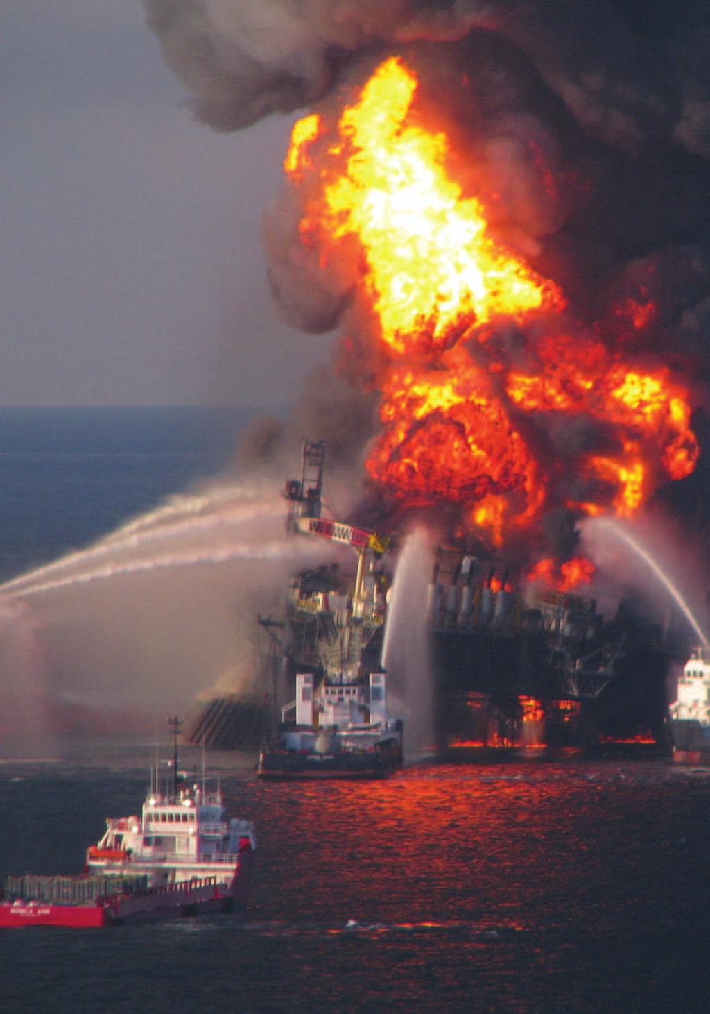
![Chapter Four 89 89 Chapter Four But, who cares, it s done, end of story, [we] will probably be fine and we ll get a good cement job.](/docs-images/78/78179453/images/2-0.jpg "The Macondo Well and the Blowout In March 2008, BP paid a little over $34 million to the Minerals Management Service for an exclusive lease to drill in Mississippi Canyon Block 252, a")
2 Chapter Four Chapter Four But, who cares, it s done, end of story, [we] will probably be fine and we ll get a good cement job. The Macondo Well and the Blowout In March 2008, BP paid a little over $34 million to the Minerals Management Service for an exclusive lease to drill in Mississippi Canyon Block 252, a nine-square-mile plot in the Gulf of Mexico. Although the Mississippi Canyon area has many productive oil fields, BP knew relatively little about the geology of Block 252: Macondo would be its first well on the new lease. BP planned to drill the well to 20,200 feet, both to learn more about the geology of the area and because it thought based on available geological data that it might find an oil and gas reservoir that would warrant installing production equipment at the well. 1 At the time, BP would have had good reason to expect that the well would be capable of generating a large profit. Little more than two years later, however, BP found itself paying out tens of billions of dollars to Fighting a losing battle, fireboats pour water onto the doomed rig in the hours after the Macondo well blowout. The tragic loss of the Deepwater Horizon at the close of the complex drilling project resulted from a series of missteps and oversights and an overall failure of management. < U.S. Coast Guard photo
3 90 National Commission on the BP Deepwater Horizon Oil Spill and Offshore Drilling contain a blowout at the Macondo well, mitigate the damage resulting from the millions of gallons of oil flowing from that well into the Gulf of Mexico, and compensate the hundreds of thousands of individuals and businesses harmed by the spill. And that is likely just the beginning. BP, its partners (Anadarko and MOEX), and its key contractors (particularly Halliburton and Transocean) face potential liability for the billions more necessary to restore natural resources harmed by the spill. The well blew out because a number of separate risk factors, oversights, and outright mistakes combined to overwhelm the safeguards meant to prevent just such an event from happening. But most of the mistakes and oversights at Macondo can be traced back to a single overarching failure a failure of management. Better management by BP, Halliburton, and Transocean would almost certainly have prevented the blowout by improving the ability of individuals involved to identify the risks they faced, and to properly evaluate, communicate, and address them. A blowout in deepwater was not a statistical inevitability. The Challenges of Deepwater Drilling at the Macondo Well High Pressures and Risk of a Well Blowout Oil forms deep beneath the Earth s surface when organic materials deposited in ancient sediments slowly transform in response to intense heat and pressure. Over the course of millions of years, these materials cook into liquid and gaseous hydrocarbons. The transformed materials can flow through porous mineral layers, and tend to migrate upward because they are lighter than other fluids in the pore spaces. If there is a path that leads to the surface, the hydrocarbons will emerge above ground in a seep or tar pit. If an impermeable layer instead blocks the way, the hydrocarbons can collect in porous rock beneath the impermeable layer. The business of drilling for oil consists of finding and tapping these pay zones of porous hydrocarbon-filled rock. Pore Pressure and Fracture Gradient Pore pressure is the pressure exerted by fluids in the pore space of rock. If drillers do not balance pore pressure with pressure from drilling fluids, hydrocarbons can flow into the wellbore (the hole drilled by the rig, including the casing) and unprotected sections of the well can collapse. The porepressure gradient, expressed as an equivalent mud weight, is a curve that shows the increase of pore pressure in a well by depth. Fracture pressure is the pressure at which the geologic formation is not strong enough to withstand the pressure of the drilling fluids in a well and hence will fracture. When fracture occurs, drilling fluids flow out of the wellbore into the formation instead of circulating back to the surface. This causes what is known as lost returns or lost circulation. The fracture gradient, expressed as an equivalent mud weight, is a curve that shows the fracture pressure of rocks in a well by depth.
4 Chapter Four The weight of the rocks above a pay zone can generate tremendous pressure on the hydrocarbons. Typically, the deeper the well, the higher the pressure and the higher the pressure, the greater the challenges in safely tapping those hydrocarbons. The first oil wells were drilled on land and involved relatively low-pressure oil reservoirs. As oil companies drilled farther offshore, they encountered large hydrocarbon deposits, often in more porous and permeable geologic formations, and, like at the Macondo well, at ever-higher pressures. The principal challenge in deepwater drilling is to drill a path to the hydrocarbon-filled pay zone in a manner that simultaneously controls these enormous pressures and avoids fracturing the geologic formation in which the reservoir is found. It is a delicate balance. The drillers must balance the reservoir pressure (pore pressure) pushing hydrocarbons into the well with counter-pressure from inside the wellbore. If too much counter-pressure is used, the formation can be fractured. But if too little counter-pressure is used, the result can be an uncontrolled intrusion of hydrocarbons into the well, and a discharge from the well itself as the oil and gas rush up and out of the well. An uncontrolled discharge is known as a blowout. Drill Pipe, Mud, Casing, Cement, and Well Control Those drilling in deepwater, just like those drilling on land, use drill pipe, casing, mud, and cement in a series of carefully calibrated steps to control pressure while drilling thousands of feet below the seafloor to reach the pay zone. Drilling mud, which is used to lubricate and cool the drill bit during drilling, plays a critical role in controlling the hydrocarbon pressure in a well. The weight of the column of mud in a well exerts pressure that counterbalances the pressure in the hydrocarbon formation. If the mud weight is too low, fluids such as oil and gas can enter the well, causing what is known as a kick. But if the mud weight is too high, it can fracture the surrounding rock, potentially leading to lost returns leakage of the mud into the formation. The rig crew therefore monitors and adjusts the weight (density) of the drilling mud as the well is being drilled one of many sensitive, technical tasks requiring special equipment and the interpretation of data from difficult drilling environments. Drilling Terminology Drilling through the seafloor does not differ fundamentally from drilling on land. The crews on any drilling rig use rotary drill bits that they lubricate and cool with drilling mud an ordinary name for what is today a sophisticated blend of synthetic fluids, polymers, and weighting agents that often costs over $100 per barrel. The rig crews pump the mud down through a drill pipe that connects with and turns the bit. The mud flows out holes in the bit and then circulates back to the rig through the space between the drill pipe and the sides of the well (the annulus), carrying to the surface bits of rock called cuttings that the drill bit has removed from the bottom of the well. When the mud returns to the rig at the surface, the cuttings are sieved out and the mud is sent back down the drill string. The mud thus travels in a closed loop. As the well deepens, the crew lines its walls with a series of steel tubes called casing. The casing creates a foundation for continued drilling by reinforcing upper portions of the hole as drilling progresses. After installing a casing string, the crews drill farther, sending each successive string of casing down through the prior ones, so the well s diameter becomes progressively smaller as it gets deeper. A completed deepwater well typically telescopes down from a starting casing diameter of three feet or more at the wellhead to a diameter of 10 inches or less at the bottom.
5 92 National Commission on the BP Deepwater Horizon Oil Spill and Offshore Drilling Casing strings, which are a series of steel tubes installed to line the well as the drilling progresses, also help to control pressures. First, they protect more fragile sections of the well structure outside the casing from the pressure of the mud inside. Second, they prevent high-pressure fluids (like hydrocarbons) outside the casing from entering the wellbore and flowing up the well. To secure the casing, crews pump in cement to seal the space between the casing and the wellbore. If a completed well can yield economically valuable oil and gas, the crews can initiate production by punching holes through the casing and surrounding cement to allow hydrocarbons to flow into the well. Designed and used properly, drilling mud, cement, and casing work together to enable the crew to control wellbore pressure. If they fail, the crew can, in an emergency, close powerful blowout-preventer valves that should seal off the well at the wellhead. Deepwater Horizon Arrives and Resumes Drilling the Well After purchasing the rights to drill in Block 252, BP became the legal operator for any activities on that block. But BP neither owned the rigs, nor operated them in the normal sense of the word. Rather, the company s Houston-based engineering team designed the well and specified in detail how it was to be drilled. A team of specialized contractors would then do the physical work of actually drilling the well a common industry practice. Transocean, a leading owner of deepwater drilling rigs, would provide BP with a rig and the crew to run it. Two BP Well Site Leaders (the company men ) would be on the rig at all times to direct the crew and contractors and their work, and would maintain regular contact with the BP engineers on shore. BP actually used two Transocean rigs to drill the Macondo well. The Marianas began work in October 2009 and drilled for 34 days, reaching a depth of 9,090 feet, before it had to stop drilling and move off-site to avoid Hurricane Ida. As described in Chapter 1, the storm nevertheless damaged the rig badly enough that BP called in the Deepwater Horizon to take over. While the Marianas had been anchored in place with huge mooring chains, the Deepwater Horizon was a dynamically positioned mobile offshore drilling unit (MODU). 2 It relied on thrusters and satellite-positioning technology to stay in place over the well. Once the rig arrived on January 31, 2010, and began drilling operations, Transocean s Offshore Installation Manager Jimmy Harrell took over responsibility as the top Transocean employee on the rig. When the Deepwater Horizon arrived, its first task was to lower its giant blowout preventer (BOP) onto the wellhead that the Marianas had left behind. The BOP is a stack of enormous valves that rig crews use both as a drilling tool and as an emergency safety device. Once it is put in place, everything needed in the well drilling pipe, bits, casing, and mud passes through the BOP. Every drilling rig has its own BOP, which its crew must test before and during drilling operations. After a week of surface testing, the Deepwater
 to guide it so that it could be latched")
6 Chapter Four FIGURE 4.1: Macondo Well Schematic TrialGraphix Horizon rig crew lowered the 400-ton device down through a mile of seawater and used a remotely operated vehicle (ROV) to guide it so that it could be latched onto the wellhead below. The Deepwater Horizon s blowout preventer had several features that could be used to seal the well. The top two were large, donut-shaped rubber elements called annular preventers that encircled drill pipe or casing inside the BOP. When squeezed shut, they sealed off the annular space around the drill pipe. The BOP also contained five sets of metal rams. The blind shear ram was designed to cut through drill pipe inside the BOP to seal off the well in emergency situations. It could be activated manually by drillers on the rig, by an ROV, or by an automated emergency deadman system. A casing shear ram was designed to cut through casing; and three sets of pipe rams were in place to close off the space around the drill pipe. Below the wellhead stretched four telescopic casing strings installed by the Marianas to reinforce the hole it had begun drilling. The Deepwater Horizon crew proceeded to drill deeper into the Earth, setting progressively smaller-diameter casing strings along the way as required. (Figure 4.1) They cemented each new string into place, anchoring the well to and sealing the well off from the surrounding rock. Lost Circulation Event at the Pay Zone, and a Revised Plan for the Well By early April, the Deepwater Horizon crew had begun to penetrate the pay zone the porous hydrocarbon-bearing rock that BP had hoped to find. But on April 9, they suffered a setback. At 18,193 feet below sea level, the pressure exerted by the drilling mud exceeded
7 94 National Commission on the BP Deepwater Horizon Oil Spill and Offshore Drilling the strength of the formation. Mud began flowing into cracks in the formation instead of returning to the rig. The rig had to stop drilling until the crew could seal the fracture and restore mud circulation. 3 Lost circulation events are a fact of life in the oil business. The crew responded with a standard industry tactic. They pumped 172 barrels of thick, viscous fluid known as a lost circulation pill down the drill string, hoping it would plug the fractures in the formation. 4 The approach worked, but BP s on-shore engineering team realized the situation had become delicate. They had to maintain the weight of the mud in the wellbore at approximately 14.0 pounds per gallon (ppg) in order to balance the pressure exerted by hydrocarbons in the pay zone. 5 But drilling deeper would exert even more pressure on the formation, pressure that the BP team measured in terms of equivalent circulating density (ECD). The engineers calculated that drilling with 14.0 ppg mud in the wellbore would yield an ECD of nearly 14.5 ppg enough of an increase that they risked further fracturing of the rock and more lost returns. Equivalent Circulating Density (ECD) A column of fluid will exert an amount of pressure on its surroundings that can be calculated if one knows the height of the column and the density of the fluid. If one pumps the fluid to make it circulate through the column, it will exert even more pressure. Equivalent circulating density or ECD is used to describe the total effective pressure that a column of drilling mud exerts on a formation as it is circulated through the drill string and back up the wellbore. To pump a given fluid faster or through narrower restrictions, it has to be pumped at greater pressure, and this, in turn, increases the ECD. The engineers concluded they had run out of drilling margin : the well would have to stop short of its original objective of 20,200 feet. 6 After cautiously drilling to a total depth of 18,360 feet, BP informed its lease partners Anadarko and MOEX that well integrity and safety issues required the rig to stop drilling further. 7 At that point, Macondo was stable. Because the column of drilling mud in the wellbore was heavy enough to balance the hydrocarbon pressure, BP and its contractors, including Transocean, were able to spend the next five days 8 between April 11 and 15 logging the open hole with sophisticated instruments. Based on the logging data, BP concluded that it had drilled into a hydrocarbon reservoir of sufficient size (at least 50 million barrels 9 ) and pressure that it was economically worthwhile to install a final production casing string that BP would eventually use to recover the oil and gas. Preparing the Well for Subsequent Production The engineers recognized that the lost circulation problems and delicacy of the rock formation at the bottom of the well would make it challenging to install the production casing. 10 After the rig crew lowered the casing into its final position, Halliburton would cement it into place. Halliburton would pump a specialized cement blend down the inside of the casing string; when it reached the end of the casing, cement would flow out the bottom and up into the annular space between the casing and the sides of the open hole. Once cured, the cement would bond to the formation and the casing and if all went

8 Chapter Four FIGURE 4.2: Long String vs. Liner Two options for the Macondo production casing. TrialGraphix well seal off the annular space. BP and Halliburton had cemented the previous casing strings at Macondo, and this cement job would be particularly important. The first attempt at cementing any casing string is commonly called the primary cement job. For a primary cement job to be successful, it must seal off, or isolate, the hydrocarbon-bearing zone from the annular space around the casing and from the inside of the casing itself. The Engineers Select a Long String Casing BP s design team originally had planned to use a long string production casing a single continuous wall of steel between the wellhead on the seafloor, and the oil and gas zone at the bottom of the well. But after the lost circulation event, they were forced to reconsider. As another option, they evaluated a liner a shorter string of casing hung lower in the well and anchored to the next higher string. (Figure 4.2) A liner would result in a more complex and theoretically more leak-prone system over the life of the well. But it would be easier to cement into place at Macondo. On April 14 and 15, BP s engineers, working with a Halliburton engineer, used sophisticated computer programs to model the likely outcome of the cementing process. When early results suggested the long string could not be cemented reliably, BP s

9 96 National Commission on the BP Deepwater Horizon Oil Spill and Offshore Drilling design team switched to a liner. But that shift met resistance within BP. 11 The engineers were encouraged to engage an in-house BP cementing expert to review Halliburton s recommendations. That BP expert determined that certain inputs should be corrected. Calculations with the new inputs showed that a long string could be cemented properly. The BP engineers accordingly decided that installing a long string was again the primary option. 12 Centralizers and the Risk of Channeling Installing the agreed-upon casing was a major job. Even moving at top speed, the crew on the Deepwater Horizon needed more than 18 hours just to lower a tool, such as a drill bit, from the rig floor to the bottom of the well, 18,000 feet below sea level. Assembling the production casing section-by-section and lowering the lengthening string down into the well below would require roughly 37 hours. 13 As the crew gradually assembled and lowered the casing, they paused several times to install centralizers (Figure 4.3) at predetermined points along the casing string. Centralizers are critical components in ensuring a good cement job. When a casing string hangs in the center of the wellbore, cement pumped down the casing will flow evenly back up the annulus, displacing any mud and debris that were previously in that space and leaving a clean column of cement. If the casing is not centered, the cement will flow preferentially up the path of least resistance the larger spaces in the annulus and slowly or not at all in the narrower annular space. That can leave behind channels of drilling mud that can severely compromise a primary cement job by creating paths and gaps through which pressurized hydrocarbons can flow. BP s original designs had called for 16 or more centralizers to be placed along the long string. 14 But on April 1, team member Brian Morel learned that BP s supplier (Weatherford) had in stock only six subs 15 centralizers designed to screw securely into place between sections of casing. The alternative was to use FIGURE 4.3: Centralizer Sub slip-on centralizers devices that slide onto the exterior of a piece of casing where they are normally secured in place by mechanical stop collars on either side. These collars can either be welded directly to the centralizers or supplied as separate pieces. The BP team and Wells Team Leader John Guide in particular distrusted slip-on centralizers with separate stop collars because the pieces can slide out of position or, worse, catch on other equipment as the casing is lowered. 16 Centralizer subs screw into place between sections of casing. Weatherford Shortly after the BP team decided on the long string, Halliburton engineer Jesse Gagliano ran computer simulations using proprietary software called OptiCem, in part to predict whether mud channeling would occur. OptiCem calculates the likely outcome of a cement job based on a number of variables, including the geometry of the wellbore and casing, the size and location of centralizers, the rate at which cement will be pumped, and the relative weight and viscosity of the cement

10 Chapter Four compared to the mud it displaces. Gagliano s calculations suggested that the Macondo production casing would need more than six centralizers to avoid channeling. Gagliano told BP engineers Mark Hafle and Brett Cocales about the problem on the afternoon of April With de facto leader John Guide out of the office, Gregory Walz, the BP Drilling Engineering Team Leader, obtained permission from senior manager David Sims to order 15 additional slip-on centralizers the most BP could transport immediately in a helicopter. That evening, Gagliano reran his simulations and found that channeling due to gas flow would be less severe with 21 centralizers in place. Late that night, Walz sent an to Guide explaining that he and Sims felt that BP needed to honor the [OptiCem] modeling to be consistent with our previous decisions to go with the long string. 18 When Guide learned the next day of the decision to add more centralizers, he initially deferred, but then challenged the decision. Walz had earlier assured Guide that the 15 additional centralizers would be custom-designed one-piece units that BP had used on a prior well FIGURE 4.4: Shoe Track and would limit the potential for centralizer hang up. 19 But when the centralizers arrived, BP engineer Brian Morel, who happened to be out on the rig, reported that the centralizers were of conventional design with separate stop collars. Morel ed BP drilling engineer Brett Cocales to question the need for additional centralizers. 20 Cocales responded that the team would probably be fine even without the additional centralizers and that Guide is right on the risk/reward equation. 21 Guide pointed out to Walz that the new centralizers were not custom-made as specified. 22 Also, he noted, it will take 10 hrs to install them. He complained that the last minute addition of centralizers would add 45 pieces of equipment to the casing that could come off during installation, and concluded by saying that he was very concerned. In the end, Guide s view prevailed; BP installed only the six centralizer subs on the Macondo production casing. Lowering the Casing String Into Position Early on the morning of April 18, with a centralizer plan in hand, the rig crew finally began assembling and lowering the long string into position. The leading end of the casing, The shoe track, showing the float collar assembly at the top and the reamer shoe at the bottom. TrialGraphix
11 98 National Commission on the BP Deepwater Horizon Oil Spill and Offshore Drilling the shoe track, began with a reamer shoe a bullet-shaped piece of metal with three holes designed to help guide the casing down the hole. (Figure 4.4) The reamer shoe was followed by 180 feet of seven-inch-diameter steel casing. Then came a Weatherfordmanufactured float collar, a simple arrangement of two flapper (float) valves, spaced one after the other, held open by a short auto-fill tube through which the mud in the well could flow. As the long string was lowered down the wellbore, the mud passed through the holes in the reamer shoe and auto-fill tube that propped open the float valves, giving it a clear flow path upward. Preparation for Cementing and Unexpected Pressure Anomalies in the Well The long string was installed in its final position early on the afternoon of April 19. With the top end of the string seated in the wellhead and its bottom end located just above the bottom of the wellbore, the crew s next job was to prepare the float-valve system for cementing. During the cementing process, fluids pumped into the well should flow in a one-way path: down the center of the last casing string, out the bottom, and up the annulus (between the exterior of the steel casing and the surrounding rock formations). To ensure unidirectional flow, the crew needed to push the auto-fill tube downward, so it would no longer prop open the float valves. With the tube out of the way, the flapper valves would spring shut and convert from two-way valves into one-way valves that would allow mud and cement to flow down the casing into the shoe track, but prevent any fluid from reversing direction and coming back up the casing. Once the float valves had converted, Halliburton could pump cement down through the casing and up around the annulus; the valves would keep cement from flowing back up the casing once the crew stopped pumping. To convert the float valves, that evening the crew began pumping mud down through the casing. Based on Weatherford s specifications, the valves should convert once the rate of flow though holes in the auto-fill tube had reached roughly 6 barrels per minute (bpm), causing a differential pressure on the tube of approximately 600 pounds per square inch (psi). 23 But the crew hit a stumbling block. They pumped fluids into the well, eventually pressuring up to 1,800 psi, but could not establish flow. Well Site Leader Bob Kaluza and BP engineer Morel 24 called Guide, their supervisor on shore. In consultation with Guide and Weatherford staff, the rig team decided to increase the pump pressure in discrete increments, hoping eventually to dislodge the auto-fill tube. 25 On their ninth attempt, pump pressure peaked at 3,142 psi and then suddenly dropped as mud finally began to flow. Significantly, however, the pump rate of mud into the well and through the shoe track thereafter never exceeded approximately 4 bpm. 26 BP s team concluded that the float valves had converted, but noted another anomaly. The drilling-mud subcontractor, M-I SWACO, had predicted that it would take a pressure of 570 psi to circulate mud after converting the float valves. 27 Instead, the rig crew reported that circulation pressure was much lower: only 340 psi. BP s Well Site Leader Bob Kaluza expressed concern about low circulating pressure. 28 He and the Transocean crew switched circulating pumps to see if that made a difference, and eventually concluded that the pressure gauge they had been relying on was broken. 29 Believing they had converted the
12 Chapter Four float valves and reestablished mud circulation in the well, BP was ready at last to pump cement down the production casing and complete the primary cement job. The Inherently Uncertain Cementing Process Cementing an oil well is an inherently uncertain process. To establish isolation across a hydrocarbon zone at the bottom of a well, engineers must send a slug of cement down the inside of the well. They then pump mud in after it to push the cement down until it turns the corner at the bottom of the well and flows up into the annular space. If done properly, the slug of cement will create a long and continuous seal around the production casing, and will fill the shoe track in the bottom of the final casing string. But things can go wrong even under optimal conditions. If the cement is pumped too far or not far enough, it may not isolate the hydrocarbon zones. If oil-based drilling mud contaminates the water-based cement as the cement flows down the well, the cement can set slowly or not at all. And, as previously noted, the cement can channel, filling the annulus unevenly and allowing hydrocarbons to bypass cement in the annular space. Given the variety of things that can go wrong with a cement job, it is hardly surprising that a 2007 MMS study identified cementing problems as one of the most significant factors leading to blowouts between 1992 and Even following best practices, a cement crew can never be certain how a cement job at the bottom of the well is proceeding as it is pumped. Cement does its work literally miles away from the rig floor, and the crew has no direct way to see where it is, whether it is contaminated, or whether it has sealed off the well. To gauge progress, the crew must instead rely on subtle, indirect indicators like pressure and volume: they know how much cement and mud they have sent down the well and how hard the pumps are working to push it. The crew can use these readings to check whether each barrel of cement pumped into the well displaces an equal volume of drilling mud producing full returns. They can also check for pressure spikes to confirm that wiper plugs (used to separate the cement from the surrounding drilling mud) have landed on time as expected at the bottom of the well. And they can look for lift pressure a steady increase in pump pressure signifying that the cement has turned the corner at the bottom of the well and is being pushed up into the annular space against gravity. While they suggest generally that the job has gone as planned, these indicators say little specific about the location and quality of the cement at the bottom of the well. None of them can take the place of pressure testing and cement evaluation logging (see below). The Cementing Design: Critical Decisions for a Fragile Formation In the days leading up to the final cementing process, BP engineers focused heavily on the biggest challenge: the risk of fracturing the formation and losing returns. John Guide explained after the incident that losing returns was the No. 1 risk. 31 He and the other BP engineers worried that if their cementing procedure placed too much pressure on the geologic formation below, it might trigger another lost-returns event similar to the one on April 9. In this case, critical cement not mud might flow into the formation and be lost, potentially leaving the annular space at the bottom of the well open to hydrocarbon flow.
13 100 National Commission on the BP Deepwater Horizon Oil Spill and Offshore Drilling The BP team s concerns led them to place a number of significant constraints on Halliburton s cementing design. The first compromise in BP s plan was to limit the circulation of drilling mud through the wellbore before cementing. Optimally, mud in the wellbore would have been circulated bottoms up meaning the rig crew would have pumped enough mud down the wellbore to bring mud originally at the bottom of the well all the way back up to the rig. There are at least two benefits to bottoms up circulation. Such extensive circulation cleans the wellbore and reduces the likelihood of channeling. And circulating bottoms up allows technicians on the rig to examine mud from the bottom of the well for hydrocarbon content before cementing. But the BP engineers feared that the longer the rig crew circulated mud through the casing before cementing, the greater the risk of another lost-returns event. Accordingly, BP circulated approximately 350 barrels of mud before cementing, rather than the 2,760 barrels needed to do a full bottoms up circulation. 32 BP compromised again by deciding to pump cement down the well at the relatively low rate of 4 barrels or less per minute. 33 Higher flow rates tend to increase the efficiency with which cement displaces mud from the annular space. But the increased pump pressure required to move the cement quickly would mean more pressure on the formation (ECD) and an increased risk of lost returns. BP decided to reduce the risk of lost returns in exchange for a less-than-optimal rate of cement flow. BP made a third compromise by limiting the volume of cement that Halliburton would pump down the well. Pumping more cement is a standard industry practice to insure against uncertain cementing conditions: more cement means less risk of contamination and less risk that the cement job will be compromised by slight errors in placement. But more cement at Macondo would mean a higher cement column in the annulus, which in turn would exert more pressure on the fragile formation below. Accordingly, BP determined that the annular cement column should extend only 500 feet above the uppermost hydrocarbon-bearing zone (and 800 feet above the main hydrocarbon zones), and that this would be sufficient to fulfill MMS regulations of 500 feet above the uppermost hydrocarbon-bearing zone. 34 However, it did not satisfy BP s own internal guidelines, which specify that the top of the annular cement should be 1,000 feet above the uppermost hydrocarbon zone. 35 As designed, BP would have Halliburton pump a total of approximately 60 barrels of cement down the well a volume that its own engineers recognized would provide little margin for error. 36 Finally, in close consultation with Halliburton, BP chose to use nitrogen foam cement a cement formula that has been leavened with tiny bubbles of nitrogen gas, injected into the cement slurry just before it goes down the well. This formula was chosen to lighten the resulting slurry from approximately 16.7 ppg to 14.5 ppg thereby reducing the pressure the cement would exert on the fragile formation. The bubbles, in theory, would also help to balance the pore pressure in the formation and clear the annular space of mud as the cement flowed upward. Halliburton is an industry leader in foam cementing, but BP appears to have had little experience with foam technology for cementing production casing in the Gulf of Mexico. 37
14 Chapter Four The Cement Slurry: Laboratory Analyses A cement slurry must be tested before it is used in a cement job. Because the pressure and temperature at the bottom of a well can significantly alter the strength and curing rate of a given cement slurry and because storing cement on a rig can alter its chemical composition over time companies like Halliburton normally fly cement samples from the rig back to a laboratory shortly before pumping a job to make sure the cement will work under the conditions in the well. The laboratory conducts a number of tests to evaluate the slurry s viscosity and flow characteristics, the rate at which it will cure, and its eventual compressive strength. When testing a slurry that will be foamed with nitrogen, the lab also evaluates the stability of the cement that results. A stable foam slurry will retain its bubbles and overall density long enough to allow the cement to cure. The result is hardened cement that has tiny, evenly dispersed, and unconnected nitrogen bubbles throughout. If the foam does not remain stable up until the time the cement cures, the small nitrogen bubbles may coalesce into larger ones, rendering the hardened cement porous and permeable. 38 If the instability is particularly severe, the nitrogen can break out of the cement, with unpredictable consequences. On February 10, soon after the Deepwater Horizon began work on the well, Jesse Gagliano asked Halliburton laboratory personnel to run a series of pilot tests on the cement blend stored on the Deepwater Horizon that Halliburton planned to use at Macondo. 39 They tested the slurry 40 and reported the results to Gagliano. He sent the laboratory report to BP on March 8 as an attachment to an in which he discussed his recommended plan for cementing an earlier Macondo casing string. 41 The reported data that Gagliano sent to BP on March 8 included the results of a single foam stability test. To the trained eye, that test showed that the February foam slurry design was unstable. Gagliano did not comment on the evidence of the cement slurry s instability, and there is no evidence that BP examined the foam stability data in the report at all. Documents identified after the blowout reveal that Halliburton personnel had also conducted another foam stability test earlier in February. The earlier test had been conducted under slightly different conditions than the later one and had failed more severely. 42 It appears that Halliburton never reported the results of the earlier February test to BP. Halliburton conducted another round of tests in mid-april, just before pumping the final cement job. By then, the BP team had given Halliburton more accurate information about the temperatures and pressures at the bottom of the Macondo well, and Halliburton had progressed further with its cementing plan. Using this information, the laboratory personnel conducted several tests, including a foam stability test, starting on approximately April 13. The first test Halliburton conducted showed once again that the cement slurry would be unstable. 43 The Commission does not believe that Halliburton ever reported this information to BP. Instead, it appears that Halliburton personnel subsequently ran a second foam stability test, this time doubling the pre-test conditioning time to three hours. 44
15 102 National Commission on the BP Deepwater Horizon Oil Spill and Offshore Drilling The evidence suggests that Halliburton began the second test at approximately 2:00 a.m. on April That test would normally take 48 hours. Halliburton finished pumping the cement job just before 48 hours would have elapsed. 46 Although the second test at least arguably suggests the foam cement design used at Macondo would be stable, it is unclear whether Halliburton had results from that test in hand before it pumped the job. Halliburton did not send the results of the final test to BP until April 26, six days after the blowout. 47 Evaluating the Cementing Job Transocean s rig crew and Halliburton s cementers finished pumping the primary cement job at 12:40 a.m. on April Once the pumps were off, a BP representative and Vincent Tabler of Halliburton performed a check to see whether the float valves were closed and holding. They opened a valve at the cementing unit to see whether any fluid flowed from the well. If more fluid came back than expected, that would indicate that cement was migrating back up into the casing and pushing the fluids above it out of the top of the well. Models had predicted 5 barrels of flow back. According to Brian Morel, the two men observed 5.5 barrels of flow, tapering off to a finger tip trickle. 49 According to Morel, 5.5 barrels of flow-back volume was within the acceptable margin for error. 50 Tabler testified that they watched flow until it was probably what we call a pencil stream, which stopped, started up again, and then stopped altogether. 51 While it is not clear how long the two men actually watched for potential flow, they eventually concluded the float valves were holding. With no lost returns, BP and Halliburton declared the job a success. Nathaniel Chaisson, one of Halliburton s crew on the rig, sent an to Jesse Gagliano at 5:45 a.m. saying, We have completed the job and it went well. 52 He attached a detailed report stating that the job had been pumped as planned and that he had seen full returns throughout the process. 53 And just before leaving the rig, Morel ed the rest of the BP team to say the Halliburton cement team... did a great job. 54 Cement Evaluation Tools Cement evaluation tools (including cement bond logs ) test the integrity of cement in the annular space around a casing. The tools measure whether and to what extent cement has bonded to the outside of the casing and formation, and the location and severity of any channels through the cement. Although a modern cement evaluation combines several different instruments, the primary approach is to analyze the casing s response to acoustic signals. Just as a muffled bell sounds different than a free-swinging bell, a well casing will respond differently depending on the volume and quality of cement around it. Cement evaluation tools do have important limits. Among other things, they work better after the cement has had time to cure completely. They also cannot evaluate cement in the shoe track of a casing, or in the annular space below the float valves. At the 7:30 a.m. morning meeting with contractors on the rig, the BP team concluded the cement job went well enough to send home a team of technicians from Schlumberger who had been standing by on the rig for at least one day already 55 waiting to perform a suite of cement evaluation tests on the primary cement job, including cement bond logs. 56 The BP team relied on a decision tree that Guide and BP engineers had prepared beforehand. The

16 Chapter Four FIGURE 4.5: Temporary Abandonment The status of the well before and after temporary abandonment. TrialGraphix primary criterion BP appears to have used to determine whether to perform the cement evaluation test was whether there were [l]osses while cementing [the] long string. 57 Having seen no lost returns during the cement job, BP sent the Schlumberger team home and moved on to prepare the well for temporary abandonment. Temporary Abandonment and Preparing to Move On to the Next Job Once BP decided to send the Schlumberger team home, Deepwater Horizon s crew began the final phase of its work. Drilling the Macondo well had required a giant offshore rig of Deepwater Horizon s capabilities. By contrast, BP, like most operators, would give the job of completing the well to a smaller (and less costly) rig, which would install hydrocarbon-collection and -production equipment. To make way for the new rig, the Deepwater Horizon would have to remove its riser * and blowout preventer from the wellhead and before it could do those things, the crew had to secure the well through a process called temporary abandonment. Four features of the temporarily abandoned well are worth noting. First is the single 300-foot-long cement plug inside the wellbore. MMS regulations required BP to install a cement plug as a backup for the cement job at the bottom of the well. Second is the location of the cement plug: BP planned to put it 3,300 feet below the ocean floor, or mud line (which was deeper than MMS regulations allowed without dispensation, and deeper than usual). 58 Third is the presence of seawater in the well below the sea floor: BP planned to replace 3,000 feet of mud in the wellbore above the cement plug with much * The riser is the piping that connects the drilling rig at the surface with the BOP at the wellhead on the seafloor.
17 104 National Commission on the BP Deepwater Horizon Oil Spill and Offshore Drilling lighter seawater (seawater weighs roughly 8.6 ppg, while the mud in the wellbore weighed roughly 14.5 ppg). Fourth is the lockdown sleeve a mechanical device that locks the long casing string to the wellhead to prevent it from lifting out of place during subsequent production operations. (Figure 4.5) At 10:43 a.m., Morel ed an Ops Note to the rest of the Macondo team listing the temporary abandonment procedures for the well. 59 It was the first time the BP Well Site Leaders on the rig had seen the procedures they would use that day. BP first shared the procedures with the rig crew at the 11 a.m. pre-tour meeting that morning. 60 The basic sequence was as follows: Lockdown Sleeve Before the Macondo blowout, a lockdown sleeve was not generally considered a safety mechanism or barrier to flow prior to the production phase of the well. Drilling rigs did not generally set lockdown sleeves. Rather, completion or production rigs did so after the drilling phase. BP decided to have the Deepwater Horizon set the lockdown sleeve because the Horizon could do the job more quickly than the completion rig. Based on the Macondo event, and given early concerns that upward forces during the blowout had approached or exceeded the force needed to lift the production casing up out of its seat in the wellhead, the Commission believes operators should consider installing a lockdown sleeve or other device to lock the casing hanger in place as part of drilling operations (or, at the very least, at the outset of temporary abandonment). 1. Perform a positive-pressure test to test the integrity of the production casing; 2. Run the drill pipe into the well to 8,367 feet (3,300 feet below the mud line); 3. Displace 3,300 feet of mud in the well with seawater, lifting the mud above the BOP and into the riser; 4. Perform a negative-pressure test to assess the integrity of the well and bottom-hole cement job to ensure outside fluids (such as hydrocarbons) are not leaking into the well; 5. Displace the mud in the riser with seawater; 6. Set the surface cement plug at 8,367 feet; and 7. Set the lockdown sleeve. 61 The crew would never get through all of the steps in the procedure. BP s Macondo team had made numerous changes to the temporary abandonment procedures in the two weeks leading up to the April 20 Ops Note. For example, in its April 12 drilling plan, BP had planned (1) to set the lockdown sleeve before setting the surface cement plug and (2) to set the surface cement plug in seawater only 6,000 feet below sea level (as opposed to 8,367 feet). The April 12 plan did not include a negativepressure test. 62 On April 14, Morel sent an entitled Forward Ops setting forth a different procedure, which included a negative-pressure test but would require setting the surface cement plug in mud before displacement of the riser with seawater. 63 On April 16, BP sent an Application for Permit to Modify to MMS describing a temporary abandonment procedure that was different from the procedure in either the April 12 drilling plan, the April 14 , or the April 20 Ops Note. 64 There is no evidence that these changes went through any sort of formal risk assessment or management of change process.
18 Chapter Four Countdown to Blowout The first step in the temporary abandonment was to test well integrity: to make sure there were no leaks in the well. The Positive-Pressure Test The positive-pressure test evaluates, among other things, the ability of the casing in the well to hold in pressure. MMS regulations require a positive-pressure test prior to temporary abandonment. 65 To perform the test at Macondo, the Deepwater Horizon s crew first closed off the well below the BOP by shutting the blind shear ram (there was no drill pipe in the well at the time). 66 Then, much like pumping air into a bike tire to check for leaks, the rig crew pumped fluids into the well (through pipes running from the rig to the BOP) to generate pressure and then checked to see if it would hold. The crew started the positive-pressure test at noon. 67 They pressured the well up to 250 psi for 5 minutes, and then pressured up to 2,500 psi and watched for 30 minutes. The pressure inside the well remained steady during both tests, showing there were no leaks in the production casing through which fluids could pass from inside the well to the outside. The drilling crew and BP s Well Site Leader Bob Kaluza considered the test successful. Later in the afternoon, Kaluza showed visiting BP executive Pat O Bryan the pressure chart from the test; O Bryan remarked, Things looked good with the positive test. 68 The Negative-Pressure Test: Unexpected Pressure Readings The negative-pressure test checks not only the integrity of the casing, like the positivepressure test, but also the integrity of the bottomhole cement job. At the Macondo well, the negative-pressure test was the only test performed that would have checked the integrity of the bottomhole cement job. Instead of pumping pressure into the wellbore to see if fluids leak out, the crew removes pressure from inside the well to see if fluids, such as hydrocarbons, leak in, past or through the bottomhole cement job. In so doing, the crew simulates the effect of removing the mud in the wellbore and the riser (and the pressure exerted by that mud) during temporary abandonment. If the casing and primary cement have been designed and installed properly, they will prevent hydrocarbons from intruding even when that overbalancing pressure is removed. 69 First, the crew sets up the well to simulate the expected hydrostatic pressure exerted by the column of fluids on the bottom of the well in its abandoned state. Second, the crew bleeds off any pent-up pressure that remains in the well, taking it down to 0 psi. Third, the crew and Well Site Leaders watch to make sure that nothing flows up from and out of the well and that no pressure builds back up inside of the well. If there is no flow or pressure buildup, that means that the casing and primary cement have sealed the well off from external fluid pressure and flow. A negative-pressure test is successful if there is no flow out of the well for a sustained period and if there is no pressure build-up inside the well when it is closed at the surface. To conduct a proper negative test at Macondo, BP would have to isolate the well from the effect of the 5,000-foot-plus column of drilling mud in the riser and a further 3,300-foot column of drilling mud below the seafloor. Those heavy columns of mud exerted much

19 106 National Commission on the BP Deepwater Horizon Oil Spill and Offshore Drilling more pressure on the well than the seawater that would replace them after temporary abandonment. Specifically, the pressure at the bottom of the well would be approximately 2,350 psi lower after temporary abandonment than before. 70 Once this pressure was removed, the downward force of the column of fluids in the well would be less than the pressure of the hydrocarbons in the reservoir, so the well would be in what is called an underbalanced state. It was therefore critical to test and confirm the ability of the well (including the primary cement job) to withstand the underbalance. If the test showed that hydrocarbons would leak into the well once it was underbalanced, BP would need to diagnose and fix the problem (perhaps remediating the cement job) before moving on, a process that could take many days. The crew began the negative test of Macondo at 5:00 p.m. Earlier in the day, the crew had prepared for the negative test by setting up the well to simulate the planned removal of the mud in the riser and 3,300 feet of drilling mud in the wellbore. The crew ran the drill pipe down to approximately 8,367 feet below sea level and then pumped a spacer a liquid mixture that serves to separate the heavy FIGURE 4.6: Displacing Mud With Spacer and Seawater Before the Negative Pressure Test drilling mud from the seawater followed by seawater down the drill pipe to push (displace) 3,300 feet of mud from below the mud line to above the BOP. (Figure 4.6) Seawater (blue) displaces mud (brown) from wellbore and riser, with spacer fluid separating the two. TrialGraphix While drilling crews routinely use water-based spacer fluids to separate oil-based drilling mud from seawater, the spacer BP chose to use during the negative pressure test was unusual. BP had directed M-I SWACO mud engineers on the rig to create a spacer out of two different lost-circulation materials left over on the rig the heavy, viscous drilling fluids used to patch fractures in the formation when the crew experiences lost returns. 71 M-I SWACO had previously mixed two different unused batches, or pills, of lost-circulation materials in case there were further lost returns. 72 BP wanted to use these materials as spacer in order to avoid having to dispose of them onshore as hazardous waste pursuant to the Resource and Conservation Recovery Act, exploiting an exception that allows companies to dump waterbased drilling fluids overboard if they have been circulated down through a well. 73 At BP s direction, M-I SWACO combined the materials to create an unusually large volume of spacer that had never previously been used by anyone on the rig or by BP as a spacer, nor been thoroughly tested for that purpose. 74
20 Chapter Four Once the crew had displaced the mud to above the BOP, they shut an annular preventer in the BOP, isolating the well from the downward pressure exerted by the heavy mud and spacer in the riser. The crew could now perform the negative-pressure test using the drill pipe: it would open the top of the drill pipe on the rig, bleed the drill pipe pressure to zero, and then watch for flow. The crew opened the drill pipe at the rig to bleed off any pressure that had built up in the well during the mud-displacement process. The crew tried to bleed the pressure down to zero, but could not get it below 266 psi. When the drill pipe was closed, the pressure jumped back up to 1,262 psi. Around this time, the driller s shack was growing crowded. The night crew was arriving in preparation for the 6:00 p.m. shift change, which meant that both toolpushers Wyman Wheeler and Jason Anderson and both Well Site Leaders Bob Kaluza and Don Vidrine were present. In addition, a group of visiting BP and Transocean executives entered as part of a rig tour escorted by Transocean Offshore Installation Manager Jimmy Harrell. 75 It was apparent to at least one member of the tour that the crew was having a little bit of a problem. 76 The crew had noticed that the fluid level inside the riser was dropping, suggesting that spacer was leaking down past the annular preventer, out of the riser, and into the well (Figure 4.7). Harrell, who stayed behind in the drill shack as the tour continued, ordered the annular preventer closed more tightly to stop the leak. 77 Harrell then left the rig floor. With that problem solved, the crew refilled the riser and once again opened up the drill pipe and attempted a second time to bleed the pressure down to 0 psi. This time, they were able to do so. But when they shut the drill pipe in again, the pressure built back up to at least 773 psi. The crew then attempted a third time to bleed off the pressure from the drill pipe, and was again able to get it down to 0 psi. When the crew shut the well back in, however, the pressure increased to 1,400 psi. At this point, the crew had bled the drill-pipe pressure down three times, but each time it had built back up. For a successful negative-pressure test, the pressure must remain at 0 psi when the pipe is closed after the pressure is bled off. The Transocean crew and BP Well Site Leaders met on the rig floor to discuss the readings. In addition to Kaluza, Vidrine, and Anderson, Dewey Revette (Transocean s on-duty driller) and BP Well Site Leader trainee Lee Lambert were there. According to post-incident statements from both Well Site Leaders, Anderson said that the 1,400 psi pressure on the drill pipe was being caused by a phenomenon called the bladder effect. 78 According to Lambert, Anderson explained that heavy mud in the riser was exerting pressure on the annular preventer, which in turn transmitted pressure to the drill pipe. Lambert said that he did not recall anyone agreeing or disagreeing with Anderson s explanation. 79 According to Harrell, after a lengthy discussion, BP Well Site Leader Vidrine then insisted on running a second negative-pressure test, this time monitoring pressure and flow on the kill line rather than the drill pipe. (The kill line is one of three pipes, each approximately 3 inches in diameter, that run from the rig to the BOP to allow the crew to circulate fluids into and out of the well at the sea floor.) The pressure on the kill line during the negativepressure test should have been identical to the pressure on the drill pipe, as both flow
.")
21 108 National Commission on the BP Deepwater Horizon Oil Spill and Offshore Drilling FIGURE 4.7: Fluids Leak Past Annular Preventer Spacer fluids (orange) leak past annular preventer. TrialGraphix paths went to the same place (and both should have been filled with seawater). Vidrine apparently insisted the negative test be repeated on the kill line because BP had specified that the test would be performed on the kill line in a permit application it submitted earlier to MMS. 80 For the second test, the crew opened the kill line and bled the pressure down to 0 psi. A small amount of fluid flowed, and then stopped. 81 Rig personnel left the kill line open for 30 minutes but did not observe any flow from it. The test on the kill line thus satisfied the criteria for a successful negative pressure test no flow or pressure buildup for a sustained period of time. But the pressure on the drill pipe remained at 1,400 psi throughout. The Well Site Leaders and crew never appear to have reconciled the two different pressure readings. 82 The bladder effect may have been proposed as an explanation for the anomaly but based on available information, the 1,400 psi reading on the drill pipe could
22 Chapter Four only have been caused by a leak into the well. Nevertheless, at 8 p.m., BP Well Site Leaders, in consultation with the crew, made a key error and mistakenly concluded the second negative test procedure had confirmed the well s integrity. They declared the test a success and moved on to the next step in temporary abandonment. Displacing Mud from the Riser and Mounting Signs of a Kick At 8:02 p.m., the crew opened the annular preventer and began displacing mud and spacer from the riser. Halliburton cementer Chris Haire went to the drill shack to check on the status of the upcoming surface cement plug job. Revette and Anderson told him the negative-pressure test had been successful and that Haire should prepare to set the surface cement plug. 83 Revette sat down in his driller s chair to monitor the well for kicks any unplanned influxes of gas or fluids and other anomalies. As gaseous hydrocarbons in a kick rise up the wellbore, they expand with ever-increasing speed a barrel of natural gas at Macondo could expand over a hundredfold as it traveled the 5,000 feet between the wellhead and the rig above. 84 And as the gas expands, it pushes mud upward faster and faster, reducing the pressure on the gas and increasing the speed of the kick making it imperative that rig crews recognize and respond to a kick as early as possible. The individuals responsible for detecting kicks on a rig include the driller, assistant drillers, and the mudlogger. 85 Dewey Revette was the driller on duty at the time; the two assistant drillers on duty were Donald Clark and Stephen Curtis. Joseph Keith of Sperry Sun was the mudlogger. These individuals look for kicks by monitoring real-time data displays in the driller s shack, mudlogger s shack, and elsewhere on the rig. They watch two primary parameters. The first, and most reliable when available, is the volume of mud in the active pits. The volume of mud sent from the active pits into the well should equal the volume of mud returning to the active pits from the well. An increase in volume is a powerful indicator that something is flowing into the well. Second, under normal circumstances, the volume and rate of flow of fluids coming from the well should equal the volume and rate of flow of fluid pumped into the well. If flow out of the well is greater than flow into the well, it is a strong indicator that a kick may be under way. Active Pit System Rigs contain multiple mud pits. The Deepwater Horizon had 20 in all. Various fluids can be stored in these pits, including drilling mud. The active pit system is a subset of the mud pits that the driller selects for monitoring purposes. In addition to these two primary parameters, the crew can perform visual flow checks. There were a number of cameras and stations on the Deepwater Horizon where the driller, mudlogger, and others could observe whether fluids were flowing from the well. When
23 110 National Commission on the BP Deepwater Horizon Oil Spill and Offshore Drilling the pumps are shut off and mud is no longer being sent into the well, flow out of the well should stop. Visual flow checks are a reliable way to monitor for kicks when pumps are off and are often used to confirm other kick indicators. Finally, the driller and mudlogger also monitor drill-pipe pressure, but it is a more ambiguous kick indicator than the other parameters because there can be many reasons for a change in drill pressure. If drill-pipe pressure decreases while the pump rate remains constant, that may indicate that hydrocarbons have entered the wellbore and are moving up the well past the sides of the drill pipe. The lighter-weight hydrocarbons exert less downward pressure, meaning the pumps do not need to work as hard to push fluids into the well. If drill-pipe pressure increases while the pump rate remains constant, that may indicate that heavier mud is being pushed up from below (perhaps by hydrocarbons) and displacing lighter fluids in the well adjacent to the drill pipe. Unexplained changes in drillpipe pressure may not always indicate a kick, but when observed should be investigated. The crew should shut down the pumps and monitor the well to confirm it is static; if they are unable to do so, they should shut in the well until the source of the readings can be determined. The Deepwater Horizon had two separate systems for collecting and displaying real-time data. The Hitec system, owned by Transocean, was the source on which the Deepwater Horizon s drilling crew typically relied for monitoring the well. The Sperry Sun system installed and operated by a Halliburton subsidiary at BP s request sent data back to shore in real time, allowing BP personnel to access and monitor this data from anywhere with an Internet connection. * Individuals on the rig could monitor data from the Sperry Sun system as well. Once the crew began displacing the riser with seawater at 8:02 p.m., they confronted the challenge of dealing with all of the returning mud. The driller repeatedly rerouted the mud returns from one pit to another in order to accommodate the incoming volume. 86 During that time, the crew also sent mud from other locations into the active pit system. 87 It is not clear whether the driller, assistant drillers, or mudlogger could adequately monitor active pit volume (or flow-in versus flow-out) during that time given all the activity. Nevertheless, things appear to have been relatively uneventful until 9:00 p.m. Drillpipe pressure was slowly but steadily decreasing over that time as lighter seawater displaced heavy drilling mud in the riser, lowering the pressure in the well and making it progressively easier to push seawater down into the well through the drill pipe. 88 At approximately 9:01 p.m., however, drill-pipe pressure (shown by the red line in Figure 4.8) began slowly increasing, despite the fact that the pump rate remained constant. 89 Over the next seven minutes, it crept slowly upward from 1,250 to 1,350 psi. 90 While the * It is difficult, if not impossible, to know precisely what the driller, assistant drillers, and mudloggers were doing and what data they were looking at between 8:00 p.m. and the first explosion at 9:49 p.m. Both the Hitec and Sperry Sun displays can be customized, and each operator typically has his own preferred set-up. Moreover, the full Hitec data set sank with the rig, leaving only the Sperry Sun subset of the data behind. Because the Sperry Sun data are all that is now available, the Commission focuses upon that data while recognizing that it is at best an approximation of what the driller, mudlogger, and others on the rig may have been looking at in the hours and minutes leading up to the blowout.

24 Chapter Four FIGURE 4.8: Increasing Drill-Pipe Pressure Sperry Sun drill-pipe pressure data (in red). magnitude of the increase may have appeared only as a subtle trend on the Sperry Sun display, the change in direction from decreasing to increasing was not. 91 Had someone noticed it, he would have had to explain to himself how the drill-pipe pressure could be increasing while the pump rate was not. One possible reason might have been that hydrocarbons were flowing into the well and pushing heavy drilling mud up past the drill pipe. The crew may have been distracted by other matters. At about that time, the last of the mud in the riser was arriving at the rig. 92 After that point, the next returning fluid would be the 400-plus barrels of spacer the crew had pumped into the well during the negativepressure test. BP planned to dump that spacer overboard, but, according to regulations, would first have to run a test to make sure that it had removed all of the oil-based mud from the riser. 93
Chapter 4 Key Findings. 4 Key Findings
 Chapter 4 Key Findings 211 4 Key Findings 212 Chapter 4 Key Findings This summarizes the key findings of the investigation team based on its extensive review of available information concerning the Macondo
Deepwater Horizon Incident Internal Investigation
 Not all Information has been verified or corroborated. Subject to review based on additional information or analysis. Deepwater Horizon Incident Internal Investigation 1 Areas of Discussion Investigation
Why Do Not Disturb Is a Safety Message for Well Integrity
 Why Do Not Disturb Is a Safety Message for Well Integrity Presented at the Practical Well Integrity Conference 9-10 December, 2014 in Houston By Ron Sweatman, Principal Advisor, Reservoir Development Services,
W I L D W E L L C O N T R O L PRESSURE BASICS AND CONCEPTS
 PRESSURE BASICS AND CONCEPTS Pressure Basics and Concepts Learning Objectives You will be familiarized with the following basic pressure concepts: Defining pressure Hydrostatic pressure Pressure gradient
Casing Design. Casing Design. By Dr. Khaled El-shreef
 Casing Design By Dr. Khaled El-shreef 1 Casing Design CONTENTS Function of Casing Casing Types & Tools Strength Properties Casing Specification Casing Design 2 1 RUNNING AND CEMENTING CASING Reasons for
RULES OF THE OIL AND GAS PROGRAM DIVISION OF WATER RESOURCES CHAPTER DRILLING WELLS TABLE OF CONTENTS
 RULES OF THE OIL AND GAS PROGRAM DIVISION OF WATER RESOURCES CHAPTER 0400-52-06 DRILLING WELLS TABLE OF CONTENTS 0400-52-06-.01 Drilling Equipment 0400-52-06-.03 Casingheads 0400-52-06-.02 Blowout Prevention
Hydro-Mech Bridge Plug
 Manual No: 0620000303 Revision: F Approved By: Quality Engineer Date: 2014-9-9 Hydro-Mech Bridge Plug DESCRIPTION: Map Hydro-Mech Bridge Plug is hydraulically actuated and mechanically set. Compact, with
W I L D W E L L C O N T R O L FLUIDS
 FLUIDS Fluids Learning Objectives You will learn about different fluids that can be used in well control. You will become familiar with the characteristics and limitations of fluids. You will learn general
Understanding pressure and pressure
 CHAPTER 1 1-1 PRESSURE BASICS Remember to think downhole. The concepts provided in this section cover the foundations for good well control. Understanding pressure and pressure relationships is important
DUO-SQUEEZE H LCM Mixing Tables and Operating Procedures
 BAROID DUO-SQUEEZE H LCM Mixing Tables and Operating Procedures Prepared for: Prepared by: Submitted by: Submittal Date: All Customers Sharath Savari, Donald L. Whitfill Halliburton January 2014 1 Copyright
OCEAN DRILLING PROGRAM
 BIH OCEAN DRILLING PROGRAM www.oceandrilling.org Scientifi c Application Packers A packer is an inflatable rubber element that inflates to seal the annular space between the drill string and the borehole
Drilling Efficiency Utilizing Coriolis Flow Technology
 Session 12: Drilling Efficiency Utilizing Coriolis Flow Technology Clement Cabanayan Emerson Process Management Abstract Continuous, accurate and reliable measurement of drilling fluid volumes and densities
APPENDIX A1 - Drilling and completion work programme
 APPENDIX A1 - Drilling and completion work programme Information about the well and drilling To the extent possible, the international system of units (SI) should be adhered to, and the drilling programme
DAY ONE. 2. Referring to the last question, what mud weight would be required to BALANCE normal formation pressure?
 DAY ONE 1. Normal formation pressure gradient is generally assumed to be: A..496 psi/ft B..564 psi/ft C..376 psi/ft D..465 psi/ft 2. Referring to the last question, what mud weight would be required to
IWCF Equipment Sample Questions (Combination of Surface and Subsea Stack)
") IWCF Equipment Sample Questions (Combination of Surface and Subsea Stack) 1. Given the volumes below, how much hydraulic fluid will be required to carry out the following operations (no safety margin)?
IWCF Equipment Sample Questions (Combination of Surface and Subsea Stack) 1. Given the volumes below, how much hydraulic fluid will be required to carry out the following operations (no safety margin)?
1. The well has been shut in on a kick and the kill operation has not started.
 Well Control Methods Day 2 1. The well has been shut in on a kick and the kill operation has not started. Shut in drill pipe pressure Shut in casing pressure 500 psi 700 psi After stabilization, both pressures
Blowout during Workover Operation A case study Narration by: Tarsem Singh & Arvind Jain, OISD
 1. Introduction An incident of gas leakage from a well took place during workover operations. Subsequently, the gas caught fire on the fourth day in which twelve persons were injured. Two contract workers,
Float Equipment TYPE 925/926
 Type 925 Float Collar Plunger Valve Float Equipment For less demanding well conditions, such as shallower depths or lower pressures, Top- Co offers economical float equipment certified to API RP 10F category
Extended leak off testing
 Extended leak off testing Rev: 1.0 03/01/01 Purpose To ensure minimal operational time and risk exposure to personnel, process, production and equipment. The following extended leak off test procedures
Case studies from classes led by Dr. Ron Fulbright, University of South Carolina Upstate. IMPROVED BLOWOUT PREVENTER
 INNOVATIVE ANALYSIS IMPROVED BLOWOUT PREVENTER 1. BRIEF DESCRIPTION OF THE SITUATION The blowout preventer (BOP) is a valve assembly usually mounted on the sea floor at the mouth of an oil well to control
SURFACE CASING SELECTION FOR COLLAPSE, BURST AND AXIAL DESIGN FACTOR LOADS EXERCISE
 SURFACE CASING SELECTION FOR COLLAPSE, BURST AND AXIAL DESIGN FACTOR LOADS EXERCISE Instructions Use the example well data from this document or the powerpoint notes handout to complete the following graphs.
Development of a Subsurface Mudline Packer to Reduce Risk of Flow after Cementing and Sustained Casing Pressure, While Providing a Platform for P&A.
 Development of a Subsurface Mudline Packer to Reduce Risk of Flow after Cementing and Sustained Casing Pressure, While Providing a Platform for P&A. Sean Yakeley, Ed Wood and Yang Xu (Baker Hughes Inc)
Rig Math. Page 1.
 Page 1 The Calculator and Main Keyboard Display Numerical 10-key pad used for entering numerical values Trigonometric Functions These keys will be used where wellbore angle is an issue These are the keys
Worked Questions and Answers
 Worked Questions and Answers A Learning Document for prospective Candidates For the Rotary Drilling Well Control Test Programme Copyright, IWCF June 2000 Revision No.1, November 2000 IWCF 2000 page 1 of
August 21, Deepwater MPD / PMCD
 August 21, 2011 Deepwater MPD / PMCD Managed Pressure Drilling (MPD) Pressure held on top of riser while drilling. Drill in overbalance condition Pressurized Mud Cap Drilling (PMCD) Pressure of mud column
IWCF Equipment Sample Questions (Surface Stack)
") IWCF Equipment Sample Questions (Surface Stack) 1. During a well control operation 4000 psi was shut in below the middle pipe rams. Ram type BOP data: Model: Cameron U type Rated Working Pressure: 15000
IWCF Equipment Sample Questions (Surface Stack) 1. During a well control operation 4000 psi was shut in below the middle pipe rams. Ram type BOP data: Model: Cameron U type Rated Working Pressure: 15000
OIL POLLUTION IN THE ARCTIC - RISKS AND MITIGATING MEASURES
 Proceedings of the ASME 2011 30th International Conference on Ocean, Offshore and Arctic Engineering OMAE2011 June 19-24, 2011, Rotterdam, The Netherlands OMAE2011-49157 OIL POLLUTION IN THE ARCTIC - RISKS
Study Guide IADC WellSharp Driller and Supervisor
 Times to Flow Check: Before pulling out of the hole Before pulling BHA into the BOP When bit is pulled into the casing Increase in cuttings at shakers with same ROP On connections Upon abnormal trip tank
DB Bridge Plug. Features. Benefits. Applications
 DB Bridge Plug The WELLFIRST Premium Cast Iron Bridge Plug designed to run on electric line. Rated between 2000-10000-psi differential, and 300 F from above and below. Features Field Proven Design Constructed
Chapter 5 HORIZONTAL DRILLING
 Chapter 5 HORIZONTAL DRILLING Chapter 5 How much money am I about to put on the table for a horizontal well? Did I do sufficient planning? Keys to Successful Horizontal Wells Multi-disciplined teams working
II. Executive Summary III. Education, Expertise, And Experience IV. Introduction... 19
 TABLE OF CONTENTS I. Scope Of Review.... 11 II. Executive Summary... 11 III. Education, Expertise, And Experience.... 17 IV. Introduction.... 19 V. BP Failed To Follow Its Own Written Practices And Violated
WILD WELL CONTROL WARNING SIGNS OF KICKS
 WARNING SIGNS OF KICKS Warning Signs of Kicks Learning Objectives You will learn the warning signs that indicate the well may be kicking: Warning signs of kicks False kick indicators You will also learn
Offshore Managed Pressure Drilling Experiences in Asia Pacific. SPE paper
 Offshore Managed Pressure Drilling Experiences in Asia Pacific SPE paper 119875 Authors: Steve Nas, Shaun Toralde, Chad Wuest, SPE, Weatherford Solutions Sdn Bhd, SPE, Weatherford Indonesia SPE, Weatherford
RPSEA UDW Forum June 22 & 23, Secure Energy for America
 RPSEA UDW Forum June 22 & 23, 2010 Secure Energy for America PROJECT TEAM RPSEA Operator Advisory Committee Anadarko Chevron Shell ConocoPhillips Subcontractors IntecSea NOV CTES General Marine Contractors
THE BUREAU OF OCEAN ENERGY MANAGEMENT, REGULATION AND ENFORCEMENT REPORT REGARDING THE CAUSES OF THE APRIL 20, 2010 MACONDO WELL BLOWOUT
 THE BUREAU OF OCEAN ENERGY MANAGEMENT, REGULATION AND ENFORCEMENT REPORT REGARDING THE CAUSES OF THE APRIL 20, 2010 MACONDO WELL BLOWOUT September 14, 2011 TABLE OF CONTENTS Executive Summary...1 I. Introduction...
SUPPLEMENT Well Control for Drilling Operations Workover & Completion for Drillers Core Curriculum and Related Learning Objectives
 SUPPLEMENT Well Control for Drilling Operations Workover & Completion for Drillers Core Curriculum and Related Learning Objectives Form WSP-02-DO-SU-WOC-D Revision 0 13 February 2015 DC 2015 COPYRGHT PROTECTED
BaraShield -664 LCM Standard Field Application Procedure
 BaraShield -664 LCM Standard Field Application Procedure Prepared for: Prepared by: Submitted by: Submittal Date: All Customers Sharath Savari, Donald L. Whitfill Halliburton March 2016 1 Copyright 2011
Commentary on the book by Andrew Hopkins. By Graham Dalzell
 Commentary on the book by Andrew Hopkins By Graham Dalzell How we drill oil wells The disaster itself how it happened; (anonymised)- oil, well and drilling companies Andrew s conclusions on the Human,
Annulus Communications Eliminated using Pressure- Activated Sealant
 SOLUTION MINING RESEARCH INSTITUTE 105 Apple Valley Circle Clarks Summit, Pennsylvania, USA Technical Conference Paper Telephone: 570-585-8092 Fax: 570-585-8091 www.solutionmining.org smri@solutionmining.org
SUPPLEMENT Well Control for Drilling Operations Workover & Completion for Supervisors Core Curriculum and Related Learning Objectives
 SUPPLEMENT Well Control for Drilling Operations Workover & Completion for Supervisors Core Curriculum and Related Learning Objectives Form WSP-02-DO-SU-WOC-S Revision 0 13 February 2015 DC 2015 COPYRGHT
1 Scope... 2 Functions of cementing float equipment... 3 Definitions... 4 Calibration... 5 Test Categories... 6 General...
 American Petroleum Institute Contents Page 1 Scope... 2 Functions of cementing float equipment... 3 Definitions... 4 Calibration... 5 Test Categories... 6 General... 7 Apparatus and Materials... 8 High-temperature/high-pressure
Casing and Cementing Requirements
 Directive PNG005 May 2018 Revision 2.0 Governing Legislation: Act: The Oil and Gas Conservation Act Regulation: The Oil and Gas Conservation Regulations, 2012 Order: 148/18 Record of Change Revision Date
Restoring Fluid Flow in Tubing Strings
 Restoring Fluid Flow in Tubing Strings Andrew Roth, Product Manager Fike Corporation Fike Hydraulic Tubing Drains (HTD) for use with deep hole drilling tools, downhole devices and other oil and off shore
Subsea Safety Systems
 Subsea Safety Systems The ELSA-HP has been developed to service the high pressure horizontal tree completion and intervention market. With systems designed and qualified up to 15,000 psi, 250 degf and
HPHT Annular Casing Packer. Obex Annular Casing Packer
 HPHT Annular Casing Packer Obex Annular Casing Packer Industry Challenge Casing packer to support second stage cement Reduce hydrostatic pressure on formation Get cement to surface Annular gas migration
Solid Expandable Tubular Technology: The Value of Planned Installation vs. Contingency
 Solid Expandable Tubular Technology: The Value of Planned Installation vs. Contingency Chris Carstens Unocal Corporation 14141 Southwest Freeway Sugar Land, Texas 77478 Mike Breaux Unocal Corporation 14141
Well Control Drill Guide Example Only. Drill Guide is the list of drills, questions and attributes that are in DrillPad.
 Well Control Drill Guide Example Only Drill Guide is the list of drills, questions and attributes that are in DrillPad. This Well Control Drill Guide will be used in conjunction with the rig-specific well
Ballast. Stability Lab Experiment. Have you ever been in a boat at sea in large waves? The boat moves up and down as the waves pass under the boat.
 Ballast & Stability Lab Experiment Have you ever been in a boat at sea in large waves? The boat moves up and down as the waves pass under the boat. In the Gulf of Mexico and other areas of the world, waves
Deepwater Horizon, by Metin Çakanyıldırım and references cited therein.
 Deepwater Horizon Page 1 Outline Summary of the events and companies Technical problems and their association with companies Managerial problems Risk averse vs. risk seeking tendencies Suggestions to avoid
Engineered solutions for complex pressure situations
 SPECIAL SERVICES Engineered solutions for complex pressure situations Cudd Energy Services (CES) delivers custom engineered solutions to resolve complex pressure situations resulting from equipment failure
R.K. Bansal, Weatherford; P.A. Bern, BP Exploration; Rick Todd, Weatherford; R.V. Baker, BP America; Tom Bailey, Weatherford
 AADE-07-NTCE-69 A Downhole Tool for Reducing ECD R.K. Bansal, Weatherford; P.A. Bern, BP Exploration; Rick Todd, Weatherford; R.V. Baker, BP America; Tom Bailey, Weatherford Copyright 2007, AADE This paper
Introduction to Ecoseal
 Ecoseal User Guide Ecoseal User Guide The following user guide has been designed to provide a step-by-step guide for the application of our Ecoseal product range. We have tried to include a range of common
Well Control Modeling Software Comparisons with Single Bubble Techniques in a Vertical Well
 Well Control Modeling Software Comparisons with Single Bubble Techniques in a Vertical Well Jace R. Larrison, P.E. Blowout Engineers, LLC Recent advances in well control modeling simulators have incorporated
1. UPDATE 12/12/2014: What wells are regulated under the MIA Program? Must they be drilled, stimulated, and completed? Must they be in production?
 PLEASE NOTE THAT ALL USES OF THE WORD OPERATOR IN THIS DOCUMENT REFER TO THE ACT 13 DEFINITION OF WELL OPERATOR AND THUS, REFERENCE THE PERMIT HOLDER (PERMITEE) FOR THE WELL. ANY ENFORCEMENT ACTIONS UNDER
Abstract Objective Scope of Study Introduction Procedures
 AADE-05-NTCE-71 A Practical Solution to Control Gas Migration Ned Shiflet, Forest Oil Corporation; Michael O. Dion, TAM International; and David P. Flores, TAM International This paper was prepared for
Investigation of Loss of Well Control Eugene Island Block 277 OCS-G Well A-2 Off the Louisiana Coast July 6, 2001
 OCS Report MMS 2002-040 Investigation of Loss of Well Control Eugene Island Block 277 OCS-G 10744 Well A-2 Off the Louisiana Coast July 6, 2001 U.S. Department of the Interior Minerals Management Service
Type 967 Diamond Broaching Type 968 Sidewinder reamer shoe
 Type 965 float collar Type 966 float shoe 1. GENERAL INFORMATION & RECOMMENDATIONS Type 967 Diamond Broaching Type 968 Sidewinder reamer shoe Type 969 Sidewinder reamer shoe Float Equipment Top-Co Float
EXAMINER S REPORT AND RECOMMENDATION STATEMENT OF THE CASE
 OIL AND GAS DO0KET NO. 01-0249550 THE APPLICATION OF REGENCY FS LP UNDER RULE 36 AND RULE 46 TO DISPOSE OF OIL AND WASTE CONTAINING HYDROGEN SULFIDE GAS INTO ITS TILDEN GPI WELL NO. 1, TILDEN, S. (WILCOX
ECD Reduction Tool. R. K. Bansal, Brian Grayson, Jim Stanley Control Pressure Drilling & Testing
 ECD Reduction Tool R. K. Bansal, Brian Grayson, Jim Stanley Control Pressure Drilling & Testing Drilling Engineering Association, Fourth Quarter Meeting November 20, 2008 1 Presentation outline Description
Hard or Soft Shut-in : Which is the Best Approach?
 HARD - SOFT shut-in? Hard or Soft Shut-in : Which is the Best Approach? March '93 INTRODUCTION There is now reasonable acceptance through-out the industry for the use of a hard shut-in procedure following
Inflatable Packers for Grouting 11/10/00
 Introduction Inflatable Packers for Grouting 11/10/00 Inflatable packers are frequently used for grout injection in geotechnical applications for structural reinforcement and/or water-proofing of foundations,
Chapter 8: Reservoir Mechanics
 PTRT 1472: Petroleum Data Management II Chapter 8: Reservoir Mechanics - Reservoir drives Types of Natural Gas Reservoir Fluids Natural gas is petroleum in a gaseous state, so it is always accompanied
New generation of solid expandable liners help give operators a jump on trouble zones
 New generation of solid expandable liners help give operators a jump on trouble zones By Pat York, Weatherford SINCE SOLID EXPANDABLE technology has gained credibility as an effective contingency option,
Marine Technology Society
 Marine Technology Society Dynamic Positioning Conference 21-22 October, 1997 Session I Review of DP Applications, Consequences and Cost of Failures Drilling Fundamentals-DP Operations-Drilling with Riser
FUNDAMENTALS OF PRESSURE REGULATORS ROBERT BENNETT MANAGER OF TRAINING ELSTER AMERICAN METER
 FUNDAMENTALS OF PRESSURE REGULATORS ROBERT BENNETT MANAGER OF TRAINING ELSTER AMERICAN METER SUPPLY = DEMAND FUNCTION OF A REGULATOR A regulator may be defined as a "mechanism for controlling or governing
float equipment OPERATING MANUAL TYPE 505/506 Float Equipment 1. INFORMATION & RECOMMENDATIONS Float Equipment
 Contents 1. GENERAL INFORMATION & RECOMMENDATIONS 1 2. INSTALLATION FLOAT EQUIPMENT 2 2.1 PRE-USE FIELD INSPECTION 2 2.2 POSITION FLOAT ON CASING STRING 3 3. RUNNING OF FLOAT EQUIPMENT 3 3.1 CIRCULATION
Advanced Applications of Wireline Cased-Hole Formation Testers. Adriaan Gisolf, Vladislav Achourov, Mario Ardila, Schlumberger
 Advanced Applications of Wireline Cased-Hole Formation Testers Adriaan Gisolf, Vladislav Achourov, Mario Ardila, Schlumberger Agenda Introduction to Cased Hole Formation tester Tool specifications Applications
Step-Rate Formation Integrity Test Method for Geothermal Wells
 GRC Transactions, Vol. 41, 2017 Step-Rate Formation Integrity Test Method for Geothermal Wells William M. Rickard, Ozgur Balamir and Ernesto Rivas Geothermal Resource Group, Inc. services@geothermalresourcegroup.com
Representing EXAMINERS REPORT AND PROPOSAL FOR DECISION STATEMENT OF THE CASE
 OIL AND GAS DOCKET NO. 03-0231502 THE APPLICATION OF JOHNSON SANFORD OPERATING COMPANY TO AMEND ITS PERMIT TO DISPOSE OF OIL AND GAS WASTE BY INJECTION INTO A POROUS FORMATION PRODUCTIVE OF OIL OR GAS,
Exercise 2-3. Flow Rate and Velocity EXERCISE OBJECTIVE C C C
 Exercise 2-3 EXERCISE OBJECTIVE C C C To describe the operation of a flow control valve; To establish the relationship between flow rate and velocity; To operate meter-in, meter-out, and bypass flow control
Model A Sleeve Valve Cement Retainer
 Ret. O.D. Model A Sleeve Valve Cement Retainer DIMENSIONAL DATA A B C D E F G H J K L M N P Q R 3.593 3.593 3.500 2.500 3.531 3.531 1.345 3.375.750.437 2.437 2.187 7.062 2.437 5.312 11.685 20.093 3.937
W I L D W E L L C O N T R O L SHUT-IN PROCEDURES
 SHUT-IN PROCEDURES Shut-in Procedures Learning Objectives You will learn general shut-in procedures: For surface BOPs. For subsea BOPs. You will learn to interpret shut-in pressures and be able to perform
VOLUMETRIC METHODS and STRIPPING OPERATIONS
 VOLUMETRIC METHODS and STRIPPING OPERATIONS WELL CONTROL SCHOOL Muscat, Oman Training Center VOLUMETRIC METHODS and STRIPPING OPERATIONS The material contained here, is based on the best sources available
Texas Administrative Code
 TITLE 16 PART 1 CHAPTER 3 RULE 3.13 Texas Administrative Code ECONOMIC REGULATION RAILROAD COMMISSION OF TEXAS OIL AND GAS DIVISION Casing, Cementing, Drilling, Well Control, and Completion Requirements
SPE Copyright 2004, Society of Petroleum Engineers Inc.
 SPE 91399 Microannulus Leaks Repaired with Pressure-Activated Sealant David W. Rusch, SPE / Seal-Tite International; Fred Sabins, SPE / Cementing Solutions, Inc.; and John Aslakson, SPE / W&T Offshore,
On-Off Connector Skirt
 On-Off Connector Skirt Retrievable Packers & Accessories The On-Off Connector Skirt is compact, reliable, fully sealing, J-type tubing disconnect device that automatically engages and releases with a small
INTERMEDIATE CASING SELECTION FOR COLLAPSE, BURST AND AXIAL DESIGN FACTOR LOADS EXERCISE
 INTERMEDIATE CASING SELECTION FOR COLLAPSE, BURST AND AXIAL DESIGN FACTOR LOADS EXERCISE Instructions Use the example well data from this document or the powerpoint notes handout to complete the following
WELL SCAVENGER. Versatile wellbore clean-up tool for the most demanding operations
 WELL SCAVENGER Versatile wellbore clean-up tool for the most demanding operations WELL SCAVENGER: A versatile wellbore cleanup tool for flowrestricted applications The inability to recover wellbore debris
SCORPION HIGH-QUALITY, FULLY COMPOSITE PLUGS
 SCORPION HIGH-QUALITY, FULLY COMPOSITE PLUGS A DIFFERENT KIND OF ENERGY COMPANY Nine Energy Service isn t your typical oilfield services company. Our success stems from a culture driven by performance
BaraBlend -665 LCM Standard Field Application Procedure
 BAROID BaraBlend -665 LCM Standard Field Application Procedure Prepared for: Prepared by: Submitted by: Submittal Date: All Customers Sharath Savari, Donald L. Whitfill Halliburton Apr 2016 1 Copyright
DEPARTMENT OF ENVIRONMENTAL PROTECTION Office of Oil and Gas Management
 DEPARTMENT OF ENVIRONMENTAL PROTECTION Office of Oil and Gas Management DOCUMENT NUMBER: 800-0810-003 TITLE: EFFECTIVE DATE: AUTHORITY: POLICY: PURPOSE: APPLICABILITY: DISCLAIMER: Guidelines for Development
Squeeze Cementing. Brett W. Williams Cementing Technical Advisor January 2016 Tulsa API Meeting
 Squeeze Cementing Brett W. Williams Cementing Technical Advisor January 2016 Tulsa API Meeting Definition Squeeze Cementing is the process of applying hydraulic pressure to force or squeeze a cement slurry
CHDT Cased Hole Dynamics Tester. Pressure testing and sampling in cased wells
 CHDT Cased Hole Dynamics Tester testing and sampling in cased wells Applications Evaluation of old wells for bypassed hydrocarbons Development of critical economic data for well evaluation Reduced-risk
Appendix K Appendix K
 Appendix K BOP Leaks There were five minor leaks in the Deepwater Horizon BOP control system: three were identified after the BOP stack was latched to the wellhead in February 2010, and two were identified
Low Pressure AutoChoke Console Precise wellbore pressure control for your underbalanced and managed-pressure drilling operations
 Low Pressure AutoChoke Console Precise wellbore pressure control for your underbalanced and managed-pressure drilling operations High resolution pressure control at your fingertips, during your UBD and
DEPARTMENT OF ENVIRONMENTAL PROTECTION Office of Oil and Gas Management
 DEPARTMENT OF ENVIRONMENTAL PROTECTION Office of Oil and Gas Management DOCUMENT NUMBER: 800-0810-003 TITLE: EFFECTIVE DATE: AUTHORITY: POLICY: PURPOSE: APPLICABILITY: DISCLAIMER: Guidelines for Development
BANDAR PANJI-1 WELL CONTROL INCIDENT REPORT
 BANDAR PANJI-1 WELL CONTROL INCIDENT REPORT EXECUTIVE SUMMARY I was requested by management to review the Banjar Panji-1 drilling operations from the conception of the Integrated Drilling Management approach
Best Practices - Coiled Tubing Deployed Ball Drop Type Perforating Firing Systems
 Best Practices - Coiled Tubing Deployed Ball Drop Type Perforating Firing Systems As a result of a recent job incident utilizing a Ball Drop Type firing system deployed on coiled tubing, the following
Hot Tapping Machine. OPERATIONS MANUAL and OPERATING INSTRUCTIONS
 262-2040 Hot Tapping Machine For performing 1/4 6 Hot taps 285 psi or less. Municipal Water, Sewage, & Building Services Use OPERATIONS MANUAL and OPERATING INSTRUCTIONS WARNING: These instructions are
A New and Simplified Method for Determination of Conductor Surface Casing Setting Depths in Shallow Marine Sediments (SMS)
") AADE-07-NTCE-41 A New and Simplified Method for Determination of Conductor Surface Casing Setting Depths in Shallow Marine Sediments (SMS) Paknejad, A., Texas A&M University; Schubert, J., Texas A&M University
AADE-07-NTCE-41 A New and Simplified Method for Determination of Conductor Surface Casing Setting Depths in Shallow Marine Sediments (SMS) Paknejad, A., Texas A&M University; Schubert, J., Texas A&M University
Practice Exam IADC WellSharp Driller and Supervisor
 Workover & Completion Day 4 1. In a workover operation of a shut in well a Lubricator is being used together with a Wireline BOP / Wireline Valve. Which Barrier is classified as the Primary Barrier? A.
Along-string pressure, temperature measurements hold revolutionary promise for downhole management
 Along-string pressure, temperature measurements hold revolutionary promise for downhole management IT S WIDELY KNOWN that the majority of stuck pipe incidents occur while pulling out of hole. If we can
Success Paths: A Risk Informed Approach to Oil & Gas Well Control
 API Winter E&P Standards Conference, Austin January 18, 2017 Success Paths: A Risk Informed Approach to Oil & Gas Well Control Dr. Dan Fraser Director, Strategic Alliances for Global Energy Solutions,
Coiled Tubing string Fatigue Management in High Pressure Milling Operation- Case Study
 Coiled Tubing string Fatigue Management in High Pressure Milling Operation- Case Study Abstract: Paper Presenter: Ebrahim Rabbani 1 e.rabbani@mehranservices.com Ebrahim Rabbani, Danial Davoodi 2, Fatemeh
Successful Deployment of a Long Gun String Via Intelligent Coiled Tubing
 Successful Deployment of a Long Gun String Via Intelligent Coiled Tubing Parry Hillis: Technical Manager BakerHughes David Ayre: BP Well Perforation Specialist Jim Gilliat: TCP/DST Business Development
Module No. # 04 Lecture No. # 3.1 Case studies (continued) (Refer Slide Time: 00:10)
 (Refer Slide Time: 00:10)") Health, Safety and Environmental Management in Petroleum and offshore Engineering Prof. Dr. Srinivasan Chandrasekaran Department of Ocean Engineering Indian Institute of Technology, Madras Module No. #
Health, Safety and Environmental Management in Petroleum and offshore Engineering Prof. Dr. Srinivasan Chandrasekaran Department of Ocean Engineering Indian Institute of Technology, Madras Module No. #
COGCC OPERATOR GUIDANCE MECHANICAL INTEGRITY TEST GUIDANCE: PRACTICES AND PROCEDURES
 COGCC OPERATOR GUIDANCE MECHANICAL INTEGRITY TEST GUIDANCE: PRACTICES AND PROCEDURES DOCUMENT CONTROL: Created Date: May 06, 2013 Last Updated Date: September 15, 2015 Last Updated By: Stuart Ellsworth
Dilution-Based Dual Gradient Well Control. Presented at the 2011 IADC Dual Gradient Workshop, 5 May 2011 by Paul Boudreau, Dual Gradient Systems LLC
 Dilution-Based Dual Gradient Well Control Presented at the 2011 IADC Dual Gradient Workshop, 5 May 2011 by Paul Boudreau, Dual Gradient Systems LLC In this very short presentation, we will Review Dilution-based
INTERPRETATION NOTE ISSUED UNDER THE PETROLEUM DRILLING REGULATIONS (CNR 1150/96)
") BOP CLASSIFICATION SYSTEM FOR ONSHORE NEWFOUNDLAND AND LABRADOR INTERPRETATION NOTE ISSUED UNDER THE PETROLEUM DRILLING REGULATIONS (CNR 1150/96) PREPARED BY THE PETROLEUM RESOURCE DEVELOPMENT DIVISION
BOP CLASSIFICATION SYSTEM FOR ONSHORE NEWFOUNDLAND AND LABRADOR INTERPRETATION NOTE ISSUED UNDER THE PETROLEUM DRILLING REGULATIONS (CNR 1150/96) PREPARED BY THE PETROLEUM RESOURCE DEVELOPMENT DIVISION
E NGINEERED C EMENTING S OLUTIONS
 DART CATCHER TOOL Blackhawk s Dart Catcher Tool provides indication of the exact location of downhole fluids during inner string cement jobs, cementing squeezes, or balanced cement plugs for temporary/permanent