Report of the Informal Working Group on the reduction of the risk of a BLEVE during transport of dangerous goods
|
|
|
- Martina Alexander
- 6 years ago
- Views:
Transcription
1 INF.23 Economic Commission for Europe Inland Transport Committee Working Party on the Transport of Dangerous Goods Joint Meeting of the RID Committee of Experts and the Working Party on the Transport of Dangerous Goods Bern, March February 2018 Item 6 of the provisional agenda Reports of informal working groups Report of the Informal Working Group on the reduction of the risk of a BLEVE during transport of dangerous goods Transmitted by Spain on behalf of the Informal Working Group Introduction 1. The Informal Working Group on the reduction of the risk of a BLEVE during transport of dangerous goods met on February 2018 in Madrid on the basis of the mandate of the RID/ADR/ADN Joint Meeting, under the chairmanship of Mr. Claude Pfauvadel (France). 2. The Informal Working Group brought together experts representing contracting parties/member states, international organisations and industry as mentioned in the enclosed list of participants. 3. The following documents were taken as the basis for the continued work: ECE/TRANS/WP.15/AC.1/148, paragraphs TRANS-WP15-AC e.pdf TRANS-WP15-AC GE-INF41a1r1e.pdf TRANS-WP15-AC GE-INF41e.pdf TRANS-WP15-AC1-17-BE-inf15e.pdf 4. Additionally, the following document was also submitted to the participants: Cost-effective application of thermal production on LPG road transport tanks for risk reduction due to hot BLEVE incidents, A.M. Birk (Risk Analysis, Vol. 34, Nº 6, 2014) 5. After the approval of the agenda, the meeting began with a presentation by INERIS of the work done until the last Joint Meeting in September 2017, and the additional cases that have been calculated since then. Sweden also briefly presented the document Cost-effective application of thermal production on LPG road transport tanks for risk reduction due to hot BLEVE incidents. 6. After that, factors important to be taken into account for the future work were analysed, and have to be further studied: Scope of work, affected substances
2 INF.23 Scope of works not only LPG; also other substances to be considered. Other gases with similar properties: ammonia, chlorine, DME. Interest in the study of LNG, but adaptations to the calculation model mentioned in the presentation are needed because LNG is refrigerated and the transport pressure is low. Some measures taken to avoid BLEVE, in particular the measures to protect the load from the fire, can be extended to pressure receptacles and could be similar to measures taken for the transport of goods of other classes (explosives?). Fire (see paragraph 7 for possible fire scenarios) Pressure relieve valves Coating Pool fire of an infinite time is an unrealistic case. Necessary parameters to define fire: heat flux, ratio of convection/radiation, flame temperature and tank emission coefficient. IAEA packaging requirements: 800ºC for 30 minutes. 900ºC is considered by some as a too high temperature, difficult to maintain even in testing facilities. Ongoing works on ISO standard for definition of full fire engulfment (ISO 21843, determination of resistance to hydrocarbon pool fires for protection systems for pressure vessels). 6.7 asks portable tanks to be able to resist a fire, unrealistic requirement. Need to consider the functioning of safety valves in tanks lying on one side, including its operation in liquid phase. PRV should be designed to not be damaged by the fire itself. Effectiveness of PRV under the different scenarios in paragraph 7 should be verified. Need to assess the reliability and behaviour of safety valves in service. UK offered to provide data based on the verification of safety valves in intermediate and periodic inspections. Investigations on different materials that could be used as coating are needed. Examples could be polyurethane coating, glass wool under thin metal layer or intumescent paint, very different behaviour. Physical properties of the coating itself have to be checked, specially aging process. Need of data to be provided by manufacturers. Scratches in case of accident can be very different depending on the material of the coating. Experiences with glass wool coating. The Netherlands offered to provide data on its experiences on the subject. Test data for physical data for properties needed (input for calculations). Calculation model used by INERIS Cost-benefit analysis It has been noted that to describe the fire the present calculation model only uses the heat flux and maximum temperature. Can be used to model scratches in coating. Properties of steel and thermal coating have been modelled separately. Improvements to the model and calculations to be done are listed in paragraph 9. Valuable information, but very sensitive to input data. 2
3 INF.23 Input data, and some of the results, does not correspond to some data available from industry experience. Industry offered to provide this data to the group. Not enough knowledge about some input data used to be conclusive. Need to agree on a common decision making criteria. This kind of analysis is more applicable as comparative assessment of different measures. 7. The group agreed that the following scenarios should be analysed using the appropriate parameters to define the fire such as heat flux, ratio of convection/radiation, flame temperature and tank emission coefficient, taking into account the dynamic evolution of fire: 1. Scenario 1: Fire coming from the own transport unit. Possible origins of the fire are the tires, cabin and the fuel tank (for road tanks only). 2. Scenario 2: Fire fuelled by the own content of the tank ( l, l for rail). Possible pool fire. 3. Scenario 3: External fire coming from a different transport unit, for example second tank containing l ( l for rail) flammable liquid, possible pool fire. 4. Scenario 4: External fire, torch fire from one tank that affects a different tank. Specially to be considered for rail transport. Different probabilities of occurrence should be assigned to each of these scenarios. The duration of the fire in the different scenarios will be limited by the combustive material present in the different scenarios. 8. The group agreed that the following measures could be interesting, both to mitigate and prevent the occurrence of a BLEVE: a. Safety valves b. Coating c. Localized automated fire extinguishing systems for tyres, engines and fuel tanks d. Local protection of load from tyres and axles for example by steel plates e. Measuring temperature increase to detect starting fires f. Measures on parking areas for dangerous goods trucks (Spain and France offered to provide data) 9. Taking into consideration the above mentioned discussions, it was agreed to try to study the inclusion into the INERIS FEM-analytical model of the convection/radiation ratio and the tank emission coefficient as parameters to model the fire and its effects. Afterwards this model could be used for analysis of the following cases with the help of it: Analysis of scenarios defined under paragraph 7 Tank lying on one side; behaviour of PRV in liquid phase Analysis of non-closing PRV Estimation of the amount of water needed to cool the tank (0,5-3,5m 3 /min?) Localized fire starting from cabin, tyres and fuel tank: will imply 3D modelling Modelling of damages caused by an accident in coating (small sized, scratches?) Modelling of LNG cryogenic vacuum insulated vessel, flammable liquids 3
4 INF.23 France and INERIS will provide a time frame of possible calculations to be done, taking into account the associated agenda and costs, to the JM meeting in March. 10. Members of the working group, and also members from the JM are invited to provide, if possible, further information on the following topics: Information on localized automated fire detection and extinguishing systems for tyres, fuel tanks and engine on board Information on systems of shields and barriers protecting tyres, fuel tanks and engine Preventive measures in parking areas to segregate dangerous goods trucks Data and photos of scratches and damages on tanks in case of accident Experiences with different types of coatings 11. This information could be sent to the Spanish expert to mercancias.peligrosas@fomento.es to be further distributed into the working group. 12. Work done by the present working group should be brought to the attention of WP15. Additionally WP15 is invited to share information on relevant work done now in WP15 as for example fire protection measures and parking supervision for road vehicles. Conclusions 13. Further work and additional data are still needed. The working group plans to meet again after calculations with the model have been done, which could be in October. Date and place of the next meeting will be defined according to the availability of data. 14. To define the new working plan and terms of reference of the group the JM is invited to consider all the mentioned work items under paragraphs 7-10 and to decide as appropriate. 15. The WG took note of the necessity to refer to the decision making guide to be produced by Risk Analysis WG hosted by ERA. As this guide has not yet been published this WG has not been able to consider it. Nevertheless, in this meeting no decision has been taken that would require a procedure such as established in that guide. Annex 16. Annexed to this document is the presentation by INERIS that served as introduction and the document Cost-effective application of thermal production on LPG road transport tanks for risk reduction due to hot BLEVE incidents (Annex 1). 17. Additionally the following documents are added, that were distributed in the working group, but not analysed yet, for further use in successive meetings (Annex 2): - List of historical BLEVES with different substances - Articles from BAM on work done in 2015 on pressure relieves valves - Images on incidents with LPG tanks 4
5 List of participants Informal Working Group on the reduction of the risk of a BLEVE during transport of dangerous goods Madrid (20-22 February 2018) Name Country Organization BALCERAK, Łukasz Poland Transportation Technical Supervision (TDT) l.balcerak@tdt.gov.pl Catry, Etienne France Ineris Etienne.catry@ineris.fr Del Prado, Luis Spain AESF ldelprado@seguridadferroviaria.es EGARDT, Erik Sweden SWEDISH CIVIL CONTINGENCIES AGENCY Erik.egardt@msb.se García Wolfrum, Silvia Spain Ministerio de Fomento sgarcia@fomento.es Hakeem, Richard UK AEGPL/UKLPG richard.hakeem@uklpg.org HEINTZ, Jean-Georges France INTERNATIONAL UNION OF RAILWAYS jean-georges.heintz@sncf.fr RIVM - National Institute for Public Health and the Mahessh, Soedesh Netherlands Environment soedesh.mahesh@rivm.nl Mairs, John UK Uk Department for Transport John.Mairs@dft.gsi.gov.uk MUÑOZ MORENO, ALFONSO JAVIER Spain APTB, Bomberos Alcorcón alfonsojmm@hotmail.com OGNIK, Henryk Poland Transportation Technical Supervision (TDT) h.ognik@tdt.gov.pl Otremba, Frank Germany BAM Frank.otremba@bam.de PAJARES PEREZ, Esteban Spain AOGPL asesoriatecnica@aoglp.com Palop Carmona, Miguel Spain EIGA Miguel_Palop_Carmona@Praxair.com 5 Pfauvaled, Claude France Ministère de la Transition Ecologique et Solidaire claude.pfauvadel@developpementdurable.gouv.fr Raucq, Philippe Belgium Service Public de Wallonie Philippe.raucq@spw.wallonie.be Rob Crewe, Andrew Ford Netherlands AEGPL (SHV Energy) rcrewe@shvenergy.com INF.23
6 6 Román, Nuria Spain Ministerio de Industria Roumier, Ariane France Ministère de la Transition Ecologique et Solidaire Würsig, Andreas Germany BAM XYDAS, Nikos Belgium AEGPL European LPG Association INF.23


7 Etienne CATRY INERIS Structural Resistance Unit Accidental Risk Division BLEVE WG Madrid DRA A Annex I Model for the thermal response of Liquefied Petroleum Gas Tanks subjected to accidental heat input
8 Summary Introduction Context INERIS model presentation Tank subjected to full fire engulfment Evaluation of a valve efficiency Evaluation of thermal coating and increased steel thickness Conclusion on the PRV/thermal coating efficiency Calculation on tanks subjected to fire on lower part Calculation assumptions Calculation results Calculation analysis Conclusion after JM Sept 2017 Calculation on tanks subjected to fire on lower part - Influence of flame temperature Input data Calculation results Summary Conclusion after the complementary calculations INERIS February 2018 DRA A 2


 BLEVE")


9 MPa Introduction Reminder of previous work: reliability of the model demonstrated Previous work: 1 development of a predictive tool to study the behaviour of different configurations tanks demonstration of reliability of the model by comparison with BAM experiments (2013) BLEVE scenario The tank is filled Tank is located in fire Boiled liquid Pressure increases Liquid level drops Safety valve opens Pressure continues to rise Strength reduction of steel Tank wall cracks BLEVE INERIS February 2018 DRA A 3 Behaviour diagramm of the tank time
 Thermal protection (safety valve,")


 Non effective protection INERIS February 2018")
10 INERIS Model presentation Description Methodological approach used for INERIS model Input Steel wall characteritics (diameter, thickness, ) Thermal protection (safety valve, coating) Lading characteristics (Level filling, Products) External thermal load characteristics MECHANICAL MODEL THERMAL MODEL Model Results Failure Criterion : Loss of containment Temperature distribution in the tank shell Temperature distribution in the lading Pression evolution Level filling evolution Stress cartography in the tank shell Effective protection No collapse Collapse Effectiveness of the measure depending on time to failure (to be defined by authorities) Non effective protection INERIS February 2018 DRA A 4
 Analytical")


 when submitted to")

11 INERIS Model presentation Description Models characteristics Finite elements model for the tank shell (insulation + steel wall) Analytical approach with a 2 phase model for the content. This model provides relevant results for tanks with a maximum capacity as used in transport (up to m 3 ). This approach is widely used in industry (ex : Vessfire software developed by Petrell As) Objective: To predict the temperature (for both phases) and pressure evolution of tanks (with or without coatings) when submitted to heat input. Safety Valve discharge Thermal loads Vapor-Wall convection Conduction Evaporation condensation Liquid-Wall convection INERIS February 2018 DRA A 5 Thermal transfers in LPG tanks under thermal loads
12 Tank subjected to full fire engulfment Evaluation of a valve efficiency - Calculation results Reminder: these results have been presented at RID ADR Joint meeting Common PRV considered (diameter 2 and P opening 16.5 bar) on LPG tank: volume 31m 3, filling rate 50% Thermal loading : full fire engulfment => Safety valve is not efficient in that case Full fire engulfment Results considering a common safety valve : risk of BLEVE INERIS February 2018 DRA A 6
13 Tank subjected to full fire engulfment Evaluation of a valve efficiency - Calculation results Test of an ideal safety valve on the same tank with the same thermal loading This safety valve set to low pressure (8 bar) is not efficient: A very low applied stress is observed as expected Failure is due to a sharp fall of Yield stress of steel This result can be generalized to all filling rate Results considering an ideal safety valve (set to 8 bar) : risk of BLEVE due to sharp fall of Yield stress of steel INERIS February 2018 DRA A 7
14 Tank subjected to full fire engulfment Evaluation of thermal coating and increased steel thickness - Calculation results 2 other protections are tested : thermal coating and increasing steel thickness of shell to 3 cm Thermal coating can avoid or delay BLEVE but several issues are raised concerning use on trucks: no retrofit about ageing behaviour with vibrations behaviour with various climatic conditions etc Increasing steel thickness of shell is efficient to avoid BLEVE, but 3 cm thick shell are needed (unfeasible) Results considering a thermal coating : no risk of BLEVE Results considering a 3 cm thick shell : no risk of BLEVE INERIS February 2018 DRA A 8
15 Conclusion about tanks subjected to full fire engulfment Conclusion on the PRV/thermal coating efficiency (RID ADR Joint meeting ) Valves are not efficient for some scenarios (ex: full fire engulfment) Other protections (thermal coating or increasing of shell thickness) may delay/avoid BLEVE but may present issues (ageing, cost, etc ) Full fire engulfment INERIS February 2018 DRA A 9
 New calculations are therefore led considering a smaller size fire scenario with the following conservative parameters: Pool fire on lower part of tank Fire reaches immediately")

16 Calculation on tanks subjected to fire on lower part Calculation assumptions Calculations led on tanks with safety valve only and subjected to a smaller size fire (localized on lower part of tank) New calculations are therefore led considering a smaller size fire scenario with the following conservative parameters: Pool fire on lower part of tank Fire reaches immediately intense burning on the entire length of the truck and has an infinite duration (a real fire can have a duration of 3 hours, and an intense burning of 30 minutes) Large fire localized on lower half of tank - Conservative hypothesis- Calculation of real fire spreading [2] [2] CFPB, Feu de pneus et de cabines sur des citernes GPL, Mai 2010 INERIS February 2018 DRA A 10
 3 scenarios are calculated for 3 filling rates (great influence on results): 85%, 50% and 30% Example of heating of a tank filling rate: 30 % INERIS February 2018 DRA-18-164468-01794A")
17 Calculation on tanks subjected to fire on lower part New calculation assumptions Characteristics of the LPG tanks: Volume: 31 m 3 Common PRV pressure relief valve- (diameter: 2 & Popening: 16.5 bar) 3 scenarios are calculated for 3 filling rates (great influence on results): 85%, 50% and 30% Example of heating of a tank filling rate: 30 % INERIS February 2018 DRA A 11
18 Calculation on tanks subjected to fire on lower part Calculation results 85 % 50 % Filling rate: 85 % -safety valve efficient no BLEVE Filling rate: 50 % - safety valve NOT efficient, BLEVE 30 % Filling rate: 30 % - safety valve NOT efficient, BLEVE INERIS February 2018 DRA A 12
19 Calculation on tanks subjected to fire on lower part Calculation analysis Previous results show the great influence of filling rate on results The impact of filling rate is explained below: Large Fire on liquid phase (Pool fire) Filling rate: 85% Filling rate: 30% FIRE The steel shell in contact with the gas phase is not impacted by the fire In that case, most of blast scenarios can be excluded with a standard PRV FIRE The steel shell in contact with the gas phase is impacted by the fire In that case, the blast risk is high (included case where the tank is equipped with an ideal PRV) INERIS February 2018 DRA A 13
20 Conclusion after the JM sept 2017 Full fire engulfment: Safety valve only can not protect tank because of mainly the reduction in the steel resistance due to high temperature Tank with an appropriate safety valve and a thermal coating could survive a full fire engulfment until it empties completely Fire on lower part only tank equipped with a common pressure relief valve : Pressure relief valve may avoid or delay BLEVE for tank with high filling rate BLEVE may occur for low filling rate, due to heating of shell in direct contact with gas INERIS February 2018 DRA A 14
21 Conclusion Way forward after the JM sept 2017: Assess the maximal fire a tank equipped with the best safety valve would survive even under low (unfavorable) filling ratio conditions In a first step lower fire temperatures were tested, with exposure of the totality of the lower half of the tank. Calculations are performed on the same tank as previously : Characteristics of the LPG tanks: Volume: 31 m³ Common PRV pressure relief valve- (diameter: 2 & Popening: 16.5 bar) INERIS February 2018 DRA A 15
22 Temperature ( C) Calculation on tanks subjected to fire on lower part - Influence of flame temperature Input data Tank are subjected to fire on lower part Radiative flux is characterized by: Flame temperature Duration Evolution of flame temperature Time (s) Real temperature field is not uniform on the lower part. Following the position temperature may be lower than 900 C Calculation are made considering uniform flame temperature between 500 C and 800 C INERIS February 2018 DRA A 16
23 Influence of flame temperature Calculation results 50% filling rate: no BLEVE for a 800 C flame temperature 800 C INERIS February 2018 DRA A 17
24 Influence of flame temperature Calculation results 30% filling rate: BLEVE for 700 and 800 C flame temperature 800 C 700 C No BLEVE for a 600 C flame temperature 600 C INERIS February 2018 DRA A 18
25 Influence of flame temperature Calculation results 10% filling rate: BLEVE for a 600 C flame temperature 600 C No BLEVE for a 500 C flame temperature EN COURS 500 C INERIS February 2018 DRA A 19
26 Influence of flame temperature Summary Influence of flame temperature / filling rate Filling rate \ Flame temperature 900 C 800 C 700 C 600 C 500 C 10% <400s 460s 680s 960s > % 400s 530s 810s >2400 > % 1200s 85% >2400s >2400s Time before BLEVE for different flame temperature / filling rate INERIS February 2018 DRA A 20
27 Conclusion after the complementary calculations Conclusion: New calculation show that even when the lower half part is totally exposed to fire a lower temperature allows the tank to survive when equipped with a valve Depending on the temperature this is possible even with low filling ratio Fire on lower part only tank equipped with a common pressure relief valve : When the filling ratio is very low the influence of the time needed for emptying the tank need to be assessed (depending in the type of valve the tank might get empty before critical pressure is reached) Filling rate : 10% Flame temperature : 800 C Popening valve : 10 bars INERIS February 2018 DRA A 21
28 Conclusion Way forward: Assess the maximal fire a tank equipped with the best safety valve would survive even under low (unfavorable) filling ratio conditions (considering possible improvement in safety valves not yet on the market) Compare this fire with the fire most likely to happen. This «typical» fire can be estimated thanks to: Refined modeling of fire using a computational fluid dynamics software (FDS Fire Dynamics Simulator) to obtain better precision on distribution of heat fluxes for 3D tank modeling Experiments Statistical assessment to estimate the most likely fire hypothesis Assess how protecting equipments (on wheels, fuel tanks, engine, cabin ) may allow to keep flame temperature under the safe value. This will allow to assess the efficiency of safety valves in terms of risk reduction INERIS February 2018 DRA A 22
29 Risk Analysis, Vol. 34, No. 6, 2014 DOI: /risa Cost-Effective Application of Thermal Protection on LPG Road Transport Tanks for Risk Reduction Due to Hot BLEVE Incidents A. M. Birk A simplified risk and cost-benefit analysis is presented for the application of thermal protection (TP) on propane and LPG highway tanker trucks operating in North America. A risk analysis is performed to determine the benefits of risk reduction by TP, relative to the costs of applying and maintaining TP on a tanker truck. The results show that TP is cost effective if the tanker truck spends enough time (or travels enough distance) in areas of moderate or high population density. The analysis is very sensitive to a number of inputs, including: (i) value of life, (ii) hot boiling liquid expanding vapor explosion frequency, (iii) public exposure to severe hazards, and (iv) life cost of TP. With this simplified analysis, it is possible to generate tanker truck exposure times to the public that justify the application of TP based on cost and benefit considerations. KEY WORDS: Cost-benefit analysis; Hot BLEVE; thermal protection 1. INTRODUCTION From time to time, road tank trucks and rail tank cars carrying propane and LPG are exposed to accidental fire impingement that can lead to catastrophic failures resulting in boiling liquid expanding vapor explosions (BLEVEs). (1) These BLEVEs produce hazards including a fireball (or flash fire, or vapor cloud explosion), blast overpressure, and far-reaching projectiles. Many studies have been conducted, (2 4) and it has been clearly demonstrated that thermal protection (TP) can dramatically reduce the likelihood of a fire-induced BLEVE (sometimes called a Hot BLEVE (5) ). However, the use of thermal TP is not widely implemented because of cost considerations (i.e., many tanks must be protected to mitigate one BLEVE). In North America (NA), rail tank cars carrying LPG and propane are required to have both TP and pressure relief valves (PRVs). However, road Department of Mechanical and Materials Engineering, Queen s University, Kingston, Ontario, Canada; birk@me.queensu.ca. tank trucks in NA carrying LPG and propane only require PRVs. Recent events in NA have triggered a reassessment of TP for highway tank trucks. In Europe, highway tankers and railway tank cars carrying LPG are not required to have TP, or a PRV. This is fundamentally different than the practice in NA. Europe is also considering TP for both rail and road tanks. Because BLEVE incidents continue to occur around the world, some countries continue to consider the application of TP and PRV to rail and highway tankers for certain dangerous goods. However, in this modern age, the implementation of such technologies must be justified by a cost-benefit analysis (CBA). The decision to use these protection measures is no longer being based on technical requirements but rather cost-benefit ratios. Of course, cost-benefit studies are hindered by many uncertainties. This article presents a simplified CBA that removes some of the complexities that appear to stall discussions of this important topic. This article is multidisciplinary as it includes mechanical and /14/ $22.00/1 C 2013 Society for Risk Analysis
30 1140 Birk Table I. Fireball Hazard Summary Tank Volume Propane Fireball Fireball Radius (m) to Heat Probability of (m 3 ) Mass (kg) D (m) Duration (seconds) Flux of 35 kw/m 2 Death at R for 35 kw/m , , , , chemical engineering, risk analysis, and CBA. The objective of this article is to present an analysis that will lead to further discussion of the important inputs to this type of analysis. This may lead to a more focused effort to obtain accurate data on these key inputs. 2. THERMAL PROTECTION TP of dangerous goods transport pressure vessels (tanks) usually involves a layer of thermal insulation to slow the heating effects of accidental fires. (2) PRVs are also used to control pressure buildup in tanks exposed to external heating. It has been shown that PRVs alone are not sufficient to protect a tank from fire if the fire is able to weaken the tank. (6) If a tank is thermally protected but is not equipped with a PRV, then if the tank fails due to fire exposure, it will fail full of product and the resulting BLEVE will be very powerful. This means the main benefit of the TP by itself is the elimination or delay of the explosion. If the explosion does happen, it will be very strong. The main benefit is delay that gives time for evacuation and emergency response. When a tank is equipped with both PRV and TP, then the TP acts to delay or prevent the explosion, and the PRV will act to reduce the pressure in the tank (i.e., reduce energy per unit mass), and to reduce the quantity (mass) of product in the vessel if there is an explosion. If there is a delayed explosion it will be less powerful because there will be less energy in the vessel at the time of failure. This was clearly shown by Townsend et al., (6) where a full-scale rail tank car Hot BLEVE was delayed by 70 minutes (relative to a unprotected tank that failed in 24 minutes), and the product mass was reduced by over 75% by the combination of a PRV with TP. In this case, the TP was a thin (3 mm) layer of intumescent paint. (7) 3. COST-BENEFIT ANALYSIS The application of TP to a fleet of tanks will be very expensive, and it may take years before this TP mitigates a single incident. For this reason, a CBA is necessary to justify such an expenditure. A detailed CBA of TP for LPG highway trucks was recently conducted by Paltrinieri et al. (8) for tanker trucks operating in the Emilia Romagna region of Italy near Bologna. They did a very detailed parametric study to show the sensitivity of the study to important input variables such as the value of human life, the life cost of TP, and the time value of money. They determined the financial benefits of the application of TP. Their study clearly showed that the final cost-benefit ratio depends very strongly on the input assumptions. 4. HAZARD ANALYSIS The hazard in this study was assumed to come from a Hot BLEVE failure of a m 3 propane road tank trailer. Such a BLEVE has the potential of producing a large fireball, blast overpressure, and projectiles. In this study, the main hazard was assumed to be the fireball that follows the BLEVE. The following have been assumed in the fireball analysis: (i) full tank contents involved with fireball, (ii) fireball surface emissive power 350 kw/m 2, (iii) fireball diameter and duration as per Roberts et al., (9) (iv) fireball lift off equals fireball diameter, (v) atmospheric attenuation as per TNO Purple Book, (10) (vi) probability of death based on probit function as per TNO Purple Book, (10) and (vii) no wind effects. Table I gives a summary of the calculated BLEVE fireball hazard effects as a function of tank size as calculated using above assumptions. As shown by Roberts et al., (9) wind effects can modify the release and this can double the thermal radiation received at a remote target outside of the fireball. The fireball duration is a curve fit to the large-scale data of Roberts et al. (9)
31 Application of TP on LPG Highway Tanker Trucks 1141 From the TNO Purple Book, (10) it is suggested that clothing and building material will ignite when exposed to 35 kw/m 2 and therefore anyone exposed to this level of heat will be a casualty. Because buildings will burn at this heat rate, it can be assumed buildings will not provide protection. (10) Other researchers choose to apply an exposure factor to account for shielding of the people in the severe hazard zone. For example, Geffen (11) used a factor of 0.1 to reduce the number of fatalities in the severe hazard zone by 90%. Clearly, this dramatically affects the number of estimated fatalities and this has a huge effect on any cost-benefit study. In this study, we have used a radius of 140 m to define the severe hazard region where the probability of death is high. The ground area of this zone is km 2. In this study, we used an exposure factor of 0.3 to determine what fraction of the people in the severe hazard zone is killed. We believe this to be a reasonable compromise between 1.0 (Purple Book (10) ) and 0.1 from Geffen. (11) These factors account for shielding by buildings, effects of unpopulated portions of the zone like roads, etc. As one would expect, these factors can change the result of a cost-benefit study quite dramatically. 5. FINANCIAL COST OF BLEVE In this study, we considered three major costs due to a BLEVE incident: (i) cost of fatalities, (ii) cost of evacuation, and (iii) cost of property damage. No attempt has been made to account for other society costs such as business or society interruptions, which are significant. Including the reduction of these costs by the application of TP would add to the benefit side of the equation. 6. VALUE OF SAVING A LIFE (VSL) A critical input to this CBA is the value of saving of a human life VSL. As described by Paltrinieri et al., (8) the value of a human life is very difficult to define. Various studies have covered a range from less than $1 million (M) to almost $100 M (2012 Canadian $). As discussed in the R2P2 document from the U.K. Health and Safety Executive, (12) the value of saving a human life used in CBA is not the same as what would be decided in a court of law if someone was accidentally killed. One way to determine a VSL in a certain context is to determine what people would be willing to pay (WTP) extra for a commodity or a service to reduce the number of fatalities per year to one less than the current value. (13) In the present context, the WTP would be the amount people are willing to pay extra per liter of LPG purchased to save one life. Then, the total volume of LPG consumed by the public would determine the WTP-based value of saving one human life. We do not have this data point for LPG. In this study, we have used $6.5 million (2012 Canadian $) as the value of saving a human life. This is the middle of the range of $3.5M $9.5M as reported in Chestnut and Di Civita (13) for a study involving human health issues. 7. OTHER COSTS We could easily account for other costs, such as property damage within the severe damage zone by specifying a property value per unit area or per person. If we know the total number of people living in the severe hazard zone, we could approximate the number of homes by dividing by the average number of occupants. This value is around 2.4 people per house (TNO Purple Book (10) ). From this, we could estimate the cost of property by multiplying by a value per home. In this case, we have used $200K (2012 Canadian $) per home. In other words, the property cost per person is $200K/2.4 = $83K or about 1.3% of a human life. We could also account for evacuation/life disruption costs by considering the number of people evacuated, and the number of days they are evacuated. The compensation per day would depend on the details of the evacuation and on how long the people are kept away from their homes and life routines. People may not be able to move back into their homes for months. One could easily imagine average compensation costs per person of between a few hundreds and several thousands of dollars. The number of people evacuated depends on the population density and how it varies with distance from the roadside. In NA, the evacuation radius for dangerous goods transportation accidents is usually 1.6 km. If we scale the number of people evacuated simply by the evacuation area versus the severe hazard area (i.e., [1,600/140] 2 = 131), we would expect about 131 evacuated people for every person in the severe hazard zone. If we assume a compensation per
32 1142 Birk person of $2,000, this would give us an evacuation cost of $261K for each person in the severe hazard zone or about 4% of the value of human life. In other words, the economics of this problem are driven by the value of human life. However, even if no lives are lost, the cost of these incidents can be very large. 8. SAMPLE INCIDENT In August 2008, a release of propane at a transfer facility in Toronto, Canada resulted in an explosion, fire, and a number of Hot BLEVE failures of LPG tank trailers. Two people died and over 12,000 people were evacuated. The main explosions happened in the middle of the night so people were in their houses sleeping, and this resulted in the small number of fatalities. There was extensive damage to many homes. With this many people evacuated in a 1.6- km radius, the population density would have been about 1,500 people/km 2 on average. Using the above costing approach, this incident had rough estimated costs of: (i) calculated loss of life cost for exposure = 1.0, $598M (1,500 people/km km 2 = 92 lives lost exposed to the fireball, Loss of life $ = $6.5M x 92 = $598M), for exposure = 0.3, $179M (loss of 28 lives), for exposure = 0.1, $60M (loss of 9 lives), actual lost life cost $13M (actual loss was two people), (ii) evacuation $24M (12,000 people evacuated $2,000 per person), (iii) off-site property damage $7.7M (92/2.4 $200K). If we use the actual lives lost, the order of magnitude cost of this incident is $45M. There is currently a $300M lawsuit before the courts over this incident. This would suggest an average compensation of $25,000 per person evacuated, or $3.3M per person in the severe hazard zone. 9. HOT BLEVE FREQUENCY The frequency of Hot BLEVEs of highway tankers is a key factor in the CBA. This frequency and the number of fatalities dominate the analysis. Frequency data for Hot BLEVEs are very limited in the public domain. In NA data, tanker truck incidents can involve releases, fires, and/or explosions. The term BLEVE is almost never used in the reporting of these incidents even when it clearly was a BLEVE. However, we know that BLEVEs do occur (Atlas Foundry in Tacoma, Washington 2007, Sunrise Propane in Toronto, Ontario in 2008) when they appear in the media. Dramatic video footage posted on the Internet from these incidents provides clear evidence that BLEVEs took place. Tanks can fail with continuous releases or catastrophic releases. If an LPG vessel suffers a catastrophic release, then that is a BLEVE (see, for example, Abbasi and Abbasi (14) ).ItmaybeaHotBLEVE (fire heating) or a Cold BLEVE (failure without fire). For example, a tanker truck that collides with a bridge and fails catastrophically is a Cold BLEVE. TP will not mitigate this type of BLEVE. However, if there is a collision that causes a leak, and a jetting fire starts, this type of event can escalate to a Hot BLEVE. TP can change the outcome of such an incident. In a recent European study, (8) it was assumed that 86% of BLEVEs are of the Hot type. A Hot BLEVE is a BLEVE caused by fire heating of the vessel. The fire weakens the tank wall and also heats the LPG to produce a much more powerful BLEVE. We will only consider this type of BLEVE because this is the one where TP has the most benefit. Hot BLEVE incidents can take place when the truck is traveling on the road, when the truck is parked, or when the truck is loading/unloading. Data suggest the highest BLEVE frequency takes place during loading/unloading. (15) For parked trucks, a Hot BLEVE may be the outcome of vandalism, or a leak, or due to domino effects at a site. On-road incidents may happen if there is a collision or a leak on road. Leaks may be caused by equipment problems, a collision, or an overfill during the loading process. Other studies (8) have also only considered onroad accidents and they have assumed the incident frequency is proportional to the distance traveled. Of course, the per kilometer incident rate also depends on the road, speed, weather, driver fatigue, road condition, driving complexity, other traffic, etc. A road incident that leads to a Hot BLEVE could have the following events: (i) Frequency of road incident F inc ; (ii) Probability of release of product or fuel P r ; (iii) Probability of fire P f ; (iv) Probability fire impinges on tank P fi ; (v) Probability of severe fire heating of vessel (in vapour space) P fis ; and
33 Application of TP on LPG Highway Tanker Trucks 1143 Table II. Hot BLEVE Frequency Estimates for Road Incidents (Data from Canada, the United States, and the European Union) Value Data from Canada (16) United States (11) United States (18) EU (3) (a) Road incident frequency 1e 7 /km/truck 1.55e 6 with release 2.8e e 7 (b) Release probability (c) Probability of fire impinging tank (d) Probability of catastrophic release F HB = (a) (b) (c) (d) Hot BLEVE 1.9e 9/km/truck 7.4e 9 4.4e 9 1.5e 9 frequency /km/truck Hot BLEVE freq for truck with 50,000 km/year 9.5e 5/truck/year 3.7e 4 2.2e 4 7.5e 5 full of product One in this number of trucks will suffer a Hot BLEVE in 30 years (vi) Probability of thermal rupture and catastrophic release (BLEVE) P B. The Hot BLEVE frequency would be determined from the above using the following: F HB = F inc P r P f P fi P fis P B. Unfortunately, the data for actual incidents are not provided in a very consistent way or at this level of detail. Table II shows the typical way incident data are presented. Based on limited data available for onroad truck incidents, the per km incident frequencies for dangerous goods vehicles are between F inc = 1e 7 (16) and 1.55e 6 (11) incidents/km/truck (see Table II). The final outcome of a Hot BLEVE has a frequency in the range of 1.5e 9 and 7.4e 9 Hot BLEVE/km/truck. If a truck travels 50,000 km/year full of product, this gives a Hot BLEVE frequency for that truck of between 7.5e 5 and 3.7e 4 Hot BLEVE/year. This only considers on-road incidents that lead to a Hot BLEVE. This is the type of incident that TP has a high probability of mitigating. Recall that this does not include loading/unloading incidents or incidents while parked, where TP can also provide a major benefit. We will focus on incidents along the road where the general public may be at risk. We have not considered the case of a tanker truck incident inside a road tunnel as described by Fabiano and Palazzi. (17) TP is likely to provide significant benefit there as well. Let us continue with a round number of 1e 4 Hot BLEVE/year/truck for the Hot BLEVE frequency of a tank truck (F HB ). This suggests that any given truck could suffer a Hot BLEVE once in 10,000 years. Over a period of 30 years, this truck has a Hot BLEVE frequency of F HB = 3e 3. Or in other words, in a fleet of 333 similar trucks we expect to see one on-road Hot BLEVE over a period of 30 years. If we thermally protect these 333 trucks, we expect to mitigate one BLEVE incident in 30 years. The benefit value from this mitigation will depend on where this truck is when it suffers a BLEVE. If the truck suffers the Hot BLEVE in the middle of nowhere, then the financial benefit would be small. If the Hot BLEVE takes place in a densely populated area, then the benefit of TP could be very large. 10. TIME VALUE OF MONEY The time value of money is usually accounted for in CBA. Different inflation rates are usually assumed for the costs and benefits. It is usually assumed that the benefits inflate faster than the costs. (12) Then, there is also a return on investment (ROI) used to discount the cash flows back to present-day dollars. These different assumptions have a significant affect on the present value (PV) of the costs and benefits. However, they have little effect on the costbenefit ratio CBR. For this reason, we will only present the costs and benefits in constant dollars. 11. PROTECTED VERSUS NONPROTECTED TANK TRUCKS In this analysis, we are considering a 45-m 3 (12,000 U.S. gals.) tank truck like those used in NA to transport LPG and propane. These tanks are required to have a PRV. They are not required to have TP. There are many benefits from TP and a PRV, including: (i) eliminated fire-induced rupture (i.e., Hot BLEVE) in most cases,
34 1144 Birk (ii) delayed fire-induced rupture (i.e., if failure is delayed, then the hazards will be reduced because there will be less product in the tank at failure due to PRV action; delay also gives time for evacuation and this reduces the number of fatalities), (iii) delayed activation of PRV under fire heating conditions (i.e., delayed hazards and domino effects), (iv) reduced average PRV flow rate under fire heating conditions (i.e., reduced hazards). 12. TP BENEFIT The TP considered in this CBA consists of a thin (3 mm) layer of intumescent paint. (7) This is similar to what was tested by Townsend et al. (6) on full-scale rail tank cars. In their full-scale fire tests, an unprotected rail tank car (125 m 3, filled to 94% capacity with propane) was exposed to an engulfing liquid hydrocarbon pool fire, and it suffered failure and a powerful BLEVE in 24 minutes. When this tank failed, it was still 40% full of liquid and it produced a very powerful BLEVE. The fill was reduced from 94% to 40% by the opening of the PRV. They then fire tested a thermally protected tank with a 3-mm layer of intumescent paint. The thickness they used (3 mm) was actually only 50% of the recommended thickness for that product. When the protected tank, filled to 85% capacity with propane, was exposed to an engulfing pool fire, the tank failed in 93 minutes. When this failure occurred, the tank was nearly empty of liquid (i.e., 3% liquid full). When this tank failed, the resulting BLEVE was much less powerful. This was a clear demonstration (40 years ago) of how TP and a PRV can change the outcome of a Hot BLEVE incident. As it turned out, this was not the TP system adopted in NA for railway tanks carrying LPG. Most rail tank-car TP systems for LPG consist of a 13-mm ceramic blanket insulation covered by a 3-mm steel jacket. (19) This type of system is heavier, possibly more effective, and it was believed to be more robust, and able to survive the harsh rail environment. 13. RISK REDUCTION BY TP + PRV Recent incidents in NA (Tacoma, Washington 2007, Toronto, Ontario 2008) have shown that jetting fires can cause LPG road tank failures in as little as six minutes. In this analysis, we have assumed two possible outcomes for the tank truck: For the unprotected truck, (i) The BLEVE takes place 10 minutes after the incident begins when the tank is still 80% full of liquid. (ii) At failure, the liquid is saturated and at 60 C. (iii) Severe hazard zone (heat flux > 35 kw/m 2 )is approximately 140 m radius. (iv) Evacuation of the immediate area is incomplete due to short time span. For the protected tank, the following assumptions have been made: (i) BLEVE is delayed to 75 minutes. (ii) When the BLEVE takes place the tank is nearly empty (3% liquid). (iii) At failure the liquid is saturated at 50 C. (iv) Severe hazard zone reduced to 75 m radius. (v) A total of 75 minutes provides time for much more effective evacuation resulting in no fatalities. The above are credible assumptions based on expert opinion. They are supported by the experimental results of Townsend et al. (6) With the above assumptions, we would get 100% risk reduction for human life. We know from testing (4,20) that TP delays 100% of Hot BLEVEs. In a high percentage of cases, the Hot BLEVE is prevented by the TP. However, we also know that TP systems can be damaged in transportation accidents so they are not 100% effective. For this reason, we have not assumed 100% effectiveness for the system. In this study, we have assumed 75% risk reduction. This assumed risk reduction applies to the on-road incident. Other incidents like loading and unloading incidents will also benefit from TP, and this would further add to the costbenefit result. With these assumptions, it is possible to generate risk reductions due to TP and individual risk (IR) and societal risk. 14. INDIVIDUAL RISK In this case, we have simplified the individual risk as follows: (i) Inside the severe hazard zone, the probability of death is 1.0. (ii) The Hot BLEVE frequency is 1.4e 9/km.
35 Application of TP on LPG Highway Tanker Trucks 1145 In other words, the individual risk is very high for people inside the severe danger zone. However, because the truck is a moving hazard, the IR for an individual standing at the side of the road at a specific position could be very small since it only takes the truck a few seconds to pass by. If we take the 140- m radius for the hazard zone then the maximum distance traveled while exposing that person to the risk is = 2 140/1,000 = 0.28 km/trip. If this truck does one such trip per week, then the final IR is 52 * 0.28 * 1.4e 9 = 2.e 8 per year, a very small and acceptable IR for that specific location on the side of the road. With this level of risk, we could accept 50 such trips per week and still have an IR of 1e 6 per year. 15. SOCIETAL RISK FROM SINGLE TRUCK For the societal risk, we must add up all the kilometers traveled by the truck and apply these kilometers to the various population densities along the roadside. We must also consider the possible fatalities within the severe hazard zone. The most severe incidents are those that involve moderate and high population densities. The highest potential for large numbers of fatalities is when the truck is on the road in a densely populated area. If a truck spends a significant fraction of its time (or km) operating in densely populated areas then the societal risk will be high. To determine the societal risk, we need to know where the truck operates. We need to know the km traveled in specific population densities. This of course is route specific and requires detailed route analysis with population data. This was done recently by Paltrinieri et al. (8) for a region in northern Italy. Here, we will consider a more generic approach. Here we will ask the question: How long can a truck operate in a populated area before TP is justified by a CBA? This will depend on the following: (i) cost of TP per year, (ii) financial benefit of saving lives, (iii) Hot BLEVE frequency, (iv) hazard exposure to the public, and (v) risk reduction by TP. 16. COST OF TP The life time cost of the TP includes the following: (i) installation cost above normal paint cost, (ii) maintenance and inspection cost above normal paint cost, and (iii) added operating cost due to added weight of TP. We have assumed the life of the vessel is 30 years. We have assumed the TP will require annual maintenance and will need a major refurbishment every 10 years. This is similar to the normal epoxy paint used on the vessel. We have assumed the use of a thin (3 mm) intumescent coating. This is simply painted on in a single coat like the normal epoxy paint used on these tanks. This results in minimal extra installation cost and minimal weight increase (i.e., negligible impact on truck capacity). It also allows for simple inspection and maintenance. In a conversation with an employee of a major manufacturer of intumescent paints, it was suggested that the total cost of installation of such paints is approximately $24/mm/m 2 for a production run of many tanks. For a 3-mm thickness, this is $72/m 2. A 45-m 3 tank trailer has a surface area of about 92 m 2, which gives an installation cost of around $6,700. If we subtract the cost of the normal epoxy paint, the cost difference for installation of the intumescent paint is around $5,000 per truck. This coating will need annual inspection and maintenance. It has been assumed the tank will be repainted very 10 years. The extra cost over normal paint has been estimated to be $30 $60K per tank over the 30-year life of the tanker, or between $1,000 and $2,000 per year assuming constant dollars. It has not been possible to obtain cost estimates more accurate than this because we do not have operational experience with these thin intumescent paints on highway tank trucks. We need field trials to obtain such experience. Earlier, we suggested that we would need to protect about 333 trucks to mitigate one Hot BLEVE incident in 30 years. This suggests an annual cost of between $0.33 and $0.67 million to protect the fleet of 333 trucks, or a cost of between $10 and $20 million to mitigate one BLEVE in 30 years. This cost is a very controversial issue with the industry. It believes that the real cost of TP will be much higher. There is a need to do field trials to determine the real costs of operating a tanker with this TP system. 17. SIMPLIFIED CBA The following assumptions and equations have been used in this simplified CBA.
36 1146 Birk As stated earlier, the basic Hot BLEVE frequency has been assumed to be: F HB = 1.32e 9 HotBLEVE/truck/km. We have assumed the average trip length tl = 300 km per loaded trip and the total number of loaded trips per year of nt = 300, for a total km/year/truck of S = 90,000. The Hot BLEVE frequency for a given population density zone z is simply the F HB times the total km traveled in that zone, or: F HBZ = F HB S z Hot BLEVE/truck in population zone z, (1) where S z = nt tl z andnt = number of trips per year and tl z is the trip length in the population zone z. The traveled distance in a zone can be converted to a time spent in that zone if we know the average truck speed traveled in that zone. A convenient way to present this is the hours per week spent in a specific zone or HPW z. HPW z = S z /V/52 hours/week in population zone z. In our case, we have assumed an average speed V = 50 km/hour. The number of fatalities was calculated assuming everyone exposed is killed in the severe hazard zone (R = 140 m, or ground area A HZ = km 2 ). We have assumed an exposure factor of EXP = 0.3. Fatalities Nz for a given population zone is: N z =PD z A HZ EXP fatalities in population zone z, where PD z = population density (people/km 2 )in zone z. As stated earlier, the assumed value of saving a human life VSL is $6.5M per life saved. The expectation value for fatalities due to a Hot BLEVE for a specific population density zone z is: EV z =Nz F HBZ fatalities/year in population zone z. The change in expectation value due to the application of TP is: dev z = RR EV z lives saved/year in population zone z, where RR is risk reduction by TP = This RR applies for a tank with both a PRV and TP. Input Name Table III. Sample Case Inputs Value for Sample LPG tank volume 45 m 3 Truck loaded trips per year 300 Loaded truck total km/year 90,000 Hot BLEVE frequency 1.32e 9/km Value of human life for CBA $6.5e6 Population exposure to hazards 0.3 Risk reduction by TP + PRV 0.75 Severe hazard zone radius 140 m Cost of TP per year $2000. From the above, the value of life saved per year for a give population zone is: VL z = dev z VSL $ per year, in population zone z. The estimated annual saving due to risk reduction is $RR and is equal to the sum of all VL z.$rr is the financial benefit per year of applying TP to that truck: n n $RR = VL z = RRPD z EXPA HZ VSLF HB S z. z=1 z=1 The assumed life cost of TP (i.e., all costs including installation, operating, maintenance, etc.) was TPC = $2,000/year (constant $). The cost-benefit ratio CBR = TPC/$RR. We have used a CBR = 1 to indicate if TP is justified. We have not applied any aversion factor. Where human life is concerned, some allow aversion factors of 10 or more (i.e., CBR = 10). (12) 18. SAMPLE CASE Here, we present a simple example based on the inputs given above. We have repeated the assumed values in Table III. Table IV shows the results for the sample case. In this sample, we have assumed a specific distribution of traveled km in each of the population zones. From this, we can calculate the Hot BLEVE frequency for each zone and from this the expected number of fatalities. For this specific example, we have calculated a financial benefit of $2,185/year or slightly greater than the $2,000 calculated for the TP cost per year. This value will of course vary dramatically if the truck spends less or more time in high population areas. As can be seen from the table, the number of dollars from risk reduction ($RR) is largest for the more
37 Application of TP on LPG Highway Tanker Trucks 1147 Table IV. Results of Sample Case Pop dens Frac of Truck Truck F HB People Fat N EV dev $ RR km/yr hr/wk Ratio peop/km 2 truck km km/trip km/trip /yr /incident /incident /yr /yr /yr in zone in zone actual in zone in zone in zone in zone in zone in zone in zone in zone in zone in zone CBR=1 CBR=1 calculated , E E E 05 $71 1,677, , E E E 06 $54 335, , E E E-05 $75 167, , E E E 05 $107 83, , E E E 05 $268 33, , , E E E 05 $322 16, , , E E E 05 $644 8, , E E E 05 $215 4, , E E E 05 $429 2, Total , E E E 04 $2, populated areas even though the tank spends little time in those areas. This is driven by the number of fatalities and the value of saving a life. 19. CRITICAL TIME FOR TP We can calculate the number of km S or hours of driving per week HPW in a given population zone that gives a cost-benefit ratio CBR = 1. The relations are shown below: S ZC = HPW ZC = TPC F HB 52 PD 2 A HZ EXP RR VSL, TPC F HB 52 V PD HZ EXP RR VSL, where V is the average truck speed in the zone. These equations give the S or HPW of tank exposure for a specific population density that gives a cost-benefit ratio for TP of unity, assuming the truck spends all of its time in that specific zone. Fig. 1 shows the result for HPW. Most trucks will have some kind of distribution of km or time over a range of population densities. Table IV includes this calculation for our sample case. The fraction of HPW or km/year exposure for each population density is calculated and then summed for all the population densities considered. If the total of those fractions is >1, then TP is justified by the cost-benefit ratio CBR <1. This approach can be used by operators or regulators to identify tank truck operations that should have TP. 20. SENSITIVITY ANALYSIS This analysis is driven by the key inputs including the Hot BLEVE frequency F HB, the value of human life VSL, the human exposure to the hazards EXP, and the cost of the thermal protection TPC. Sadly, we do not have precise values for any of these. Any and all of these factors could easily be adjusted up or down by a factor of 2 or more. In other words, with different input assumptions, this CBA could easily result in cost-benefit ratios of between 0.2 and 5. Recall that we did not apply any aversion factor to account for the loss of many lives. Aversion factors can easily exceed a value of 10 or more. In other words, a CBR of 5 when life is at risk is probably acceptable. In NA, rail tank cars were thermally protected in the 1980s without a cost-benefit study. Because of a series of major incidents, transportation regulators decided it was in the public s best interest to have TP. 21. CONCLUSIONS A simplified CBA is presented for the application of TP on propane and LPG tanker trucks operating in NA. The results show that TP is cost effective if the tanker truck spends enough time operating in areas of moderate or high population density. The analysis is very sensitive to a number of inputs, including: (i) value of life, (ii) Hot BLEVE frequency, (iii) public exposure to severe hazards, and (iv) cost of TP. This analysis has only considered the benefits of TP for on-road incidents. If other incidents were included such as:
38 1148 Birk Fig. 1. Driving hours per week (HPW) exposure to the public versus population density that gives a cost-benefit ratio of unity for application of thermal protection. Assumed Hot BLEVE frequency is 1.32e 9/km. (i) loading/unloading, and (ii) while parked (on-site fire domino effects), the cost-benefit ratio would be even more favorable for TP. This analysis includes many uncertainties, the most important being the frequency of on-road Hot BLEVEs and the number of fatalities resulting from an incident. There is very limited data on both. ACKNOWLEDGMENTS This work was funded by the Natural Sciences and Engineering Research Council of Canada under the Discovery Grants program. REFERENCES 1. Birk AM, Cunningham MH. The boiling liquid expanding vapour explosion. International Journal of Loss Prevention in the Process Industries, 1995; 7: Anderson CE. Rail tank car safety by fire protection. Proceedings of the 6th International Fire Protection Seminar, Paltrinieri N, Landucci G, Molag M, Bonvicini S, Spadoni G, Cozzani V. Risk reduction in road and rail LPG transportation by passive fire protection. Journal of Hazardous Materials, 2009; 167: Droste B, Schoen W. Full scale fire tests with unprotected and thermal insulated LPG storage tanks. Journal of Hazardous Materials, 1988; 20: Birk AM, Maillette J, Cunningham MH. Hot and cold BLEVEs: Observation and discussion of two different kinds of BLEVEs. Presented at the AiChE Heat Transfer Conference, AiChE Symposium Series Volume 89, Atlanta, Townsend W, Anderson CE, Zook J, Cowgill G. Comparison of thermally coated and uninsulated rail tank-cars filled with LPG subjected to a fire environment. U.S. DOT Report, Hao J, Chow WK. A brief review of intumescent fire retardant coatings. Architectural Science Review, 2003; 46: Paltrinieri N, Bonvicini S, Spadoni G, Cozzani V. Cost benefit analysis of passive fire protections in road LPG transportation. Risk Analysis, 2012; 32: Roberts TA, Goose A, Hawksworth S. Thermal radiation from fireballs on failure of liquefied petroleum gas storage vessels. Process Safety and Environmental Protection, 2000; 78(3): van Geel PLBA. Guidelines for Quantitative Risk Assessment (Purple Book). The Netherlands: The State Secretary of Housing, Spacial Planning and the Environment, VROM, Geffen CA. An assessment of the risk of transporting propane by truck and train. DE-AC06 76RLO 1830, Reducing risks, protecting people (R2P2): HSE s decisionmaking process. UK Health and Safety Executive, Chestnut LG, Di Civita P. Economic valuation of mortality risk reduction: Review and recommendations for policy and regulatory analysis. P. R. I. Government of Canada, Ed, Abbasi T, Abbasi SA. The boiling liquid expanding vapour explosion (BLEVE): Mechanism, consequence assessment, management. Journal of Hazardous Materials, 2007; 141: Casal J. Evaluation of the Effects and Consequences of Major Accidents in Industrial Plants. Industrial Safety Series, Vol. 8. Elsevier, B.V., Button NP. Release and Fire Incident Rates for Trucks Carrying Dangerous Goods, PhD Thesis, University of Waterloo, Ontario, Canada, Fabiano B, Palazzi E. HazMat transportation by heavy vehicles and road tunnels: A simplified modelling procedure to risk assessmentandmitigationappliedtoanitaliancasestudy.international Journal of Heavy Vehicle Systems, 2010; 17: Abkowitz M, DeLorenzo J, Duych R, Greenberg A, Mc- Sweeney T. Comparative risk assessment of hazmat and nonhazmat truck shipments. Proceedings of the Annual Meeting of Transportation Research Board, Birk AM, Cunningham MH. Tank-car insulation defect assessment criteria: Thermal analysis of defects. Transport Canada Report, Landucci G, Molag M, Reinders J, Cozzani V. Experimental and analytical investigation of thermal coating effectiveness for 3 m 3 LPG tanks engulfed by fire. Journal of Hazardous Materials, 2009; 161:
39 Annex II CHAPTER 22 MODELING AND UNDERSTANDING BLEVEs J. Casal, J. Arnaldos, H. Montiel, E. Planas-Cuchi, and J. A. Vílchez Centre d Estudis del Risc Tecnològic (CERTEC), Universitat Politècnica de Catalunya Institut d Estudis Catalans, Barcelona, Catalonia, Spain 22.1 INTRODUCTION Boiling liquid expanding vapor explosions (BLEVEs) are one of the most severe accidents that can occur in the process industry or in the transportation of hazardous materials. Strictly speaking, these explosions do not necessarily imply thermal effects. However, in most cases the substance involved is a fuel that causes a severe fireball after the explosion. Usually BLEVE refers to the combination of these two phenomena, BLEVE and fireball, i.e., to an accident simultaneously involving mechanical and thermal effects. BLEVEs occur with a certain frequency: the substances that can lead to them (butane, propane, vinyl chloride, chlorine, etc.) are relatively common in the industry, as well as the installations in which they can happen (tanks and tank cars). They can have diverse origins, such as runaway reactions and collisions, but the most frequent one is the action of fire on a container. Table 22.1 (Prugh, 1991) shows a list of the most significant BLEVEs that have occurred between 1926 and As can be seen, most of these involved fatalities. Another source (Londiche and Guillemet, 1991) mentions 900 fatalities and over 9,000 injured in 77 BLEVEs occurring between 1941 and In this section, the main features of BLEVEs and fireballs are discussed and a practical methodology for estimating their effects is described. The information provided in Table 22.1 allows a simple statistical analysis to determine the most frequent external causes of BLEVEs. The results obtained can be seen in Table Some of these causes can occur simultaneously (for example, among the 18 cases of fire, 5 happened immediately after a derailing). Nevertheless, this information shows the importance of fire, overfilling, and runaway reactions both in fixed installations and during transport DESCRIPTION OF THE PHENOMENON If a tank containing a pressurized liquid is heated for example, due to the thermal radiation from a fire the pressure inside it will increase. At a certain moment, its walls will not be 22.1
40 22.2 CHAPTER TWENTY-TWO TABLE 22.1 The Most Significant BLEVE Accidents from 1926 to 1986 Date Place Cause Material Tons Fatalities 12/ 13/ 1926 St. Auban, France Overfilling Chlorine / 28/ 1928 Hamburg, Germany Runaway reaction Phosgene /10/1929 Syracuse, NY, U.S.A. Explosion (H 2 ) Chlorine / 24/ 1939 Zarnesti, Rumania Overfilling Chlorine / 29/ 1943 Ludwigshafen, Germany Overfilling Butadiene /5/1947 Roemo, Finland Overfilling Chlorine / 28/ 1948 Ludwigshafen, Germany Overfilling Ethyl ester /7/1951 Port Newark, NJ, U.S.A. Fire Propane 2, /4/1952 Walsum, Germany Overfilling Chlorine /4/1954 Institute, WV, U.S.A. Runaway reaction Acrolein /8/1957 Montreal, Quebec, Canada Fire Butane? Alma, MI, U.S.A. Overfilling Butane / 28/ 1959 Meldria, U.S.A. Derailing Propane / 18/ 1959 Kansas City, U.S.A. Fire Gasoline / 17/ 1962 Doe Run, MO, U.S.A. Runaway reaction Ethylene oxide /4/1966 Feyzin, France Fire Propane 1, /1/1968 Donreith, U.S.A. Derailing (fire) Ethylene oxide 2 0 8/ 21/ 1968 Lieven, France Mechanical Ammonia /2/1969 Repcelak, Hungary Overfilling Carbon dioxide / 25/ 1969 Laurel, MS, U.S.A. Derailing (fire) Propane / 18/ 1969 Crete, NE, U.S.A. Derailing Ammonia / 29/ 1969 Cumming, IA, U.S.A. Derailing Ammonia?? 9/ 11/ 1969 Glendora, CA, U.S.A. Fire Vinyl chloride / 21/ 1970 Crescent City, IL, U.S.A. Derailing (fire) Propane / 19/ 1970 Baton Rouge, LA, U.S.A. Overpressure Ethylene / 19/ 1971 Houston, TX, U.S.A. Derailing (fire) Vinyl chloride /9/1972 Tewksbury, MA, U.S.A. Collision Propane / 30/ 1972 Rio de Janeiro, Brazil Fire Propane 1, / 21/ 1972 Turnpike, NJ, U.S.A. Collision Propylene /2/1972 San Antonio, TX, U.S.A. Corrosion Carbon dioxide /5/1973 Kingman, AZ, U.S.A. Fire Propane / 11/ 1974 West St. Paul, MN, U.S.A. Fire Propane / 12/ 1974 Oneonta, NV, U.S.A. Derailing (fire) Propane / 29/ 1974 Pueblo, CO, U.S.A. Fire Propane / 29/ 1975 Eagle Pass, TX, U.S.A. Collision Propane / 14/ 1975 Niagara Falls, NY, U.S.A. Runaway reaction Chlorine / 11/ 1976 Houston, TX, U.S.A. Collision Ammonia / 31/ 1976 Gadsden, AL, U.S.A. Fire Gasoline Cartagena, Colombia Overpressure Ammonia / 22/ 1978 Waverly, TN, U.S.A. Derailing Propane / 11/ 1978 Els Alfacs, Spain Dilatation/ overpressure Propylene / 30/ 1978 Texas City, TX, U.S.A. Fire Butane 1, / 30/ 1979 Good Hope, LA, U.S.A. Ship collision Butane /1/1981 Montonas, Mexico Derailing Chlorine / 19/ 1982 Spencer, USA Overheating Water / 11/ 1982 Taft, LA, U.S.A. Runaway reaction Acrolein / 12/ 1983 Reserve, LA, U.S.A. Runaway reaction Chlorobutadiene /4/1983 Houston, TX, U.S.A. Overfilling Methyl bromide / 19/ 1984 Mexico City, Mexico Fire Propane 3, / 28/ 1986 Kennedy Space Center, FL, U.S.A. Fire Hydrogen Source: Prugh, 1991.
41 MODELING AND UNDERSTANDING BLEVEs 22.3 TABLE 22.2 The Most Frequent External Causes of BLEVEs Cause % Fire 26 Derailing 20 Overfilling 18 Runaway reaction 12 Collision 10 Overpressure 6 Other 8 able to withstand the high stress and they will collapse (the steel typically used for the construction of LPG vessels may fail at pressures of about 15 atm, when the temperature of the walls reaches approximately 650 C). This is most likely to occur in the top section of the container, where the walls are not in contact with the liquid and therefore not cooled by it; the temperature of the walls will increase and their mechanical resistance will decrease (Birk, 1995). Instead, the wall in contact with the liquid will transfer heat to the liquid, thus maintaining a much lower temperature. If a safety valve opens, the boiling liquid will have a stronger cooling action due to the heat of evaporation. Upon failure, due to the instantaneous depressurization, the temperature of the liquid will be greater than that corresponding to the new pressure according to the saturation curve in the P-T diagram. In this unstable condition, it is called superheated liquid. Liquids normally can withstand a small amount of superheating, which in certain experimental conditions can be extended far above the atmospheric-pressure boiling point (Prugh, 1991). However, there is a limit to superheat, called the superheat temperature limit (different for each substance). Then, if the temperature of the liquid at the moment of depressurization is higher than the superheat temperature limit, a violent and instantaneous flash of a fraction of the liquid and a superheated liquid vapor explosion will take place; a biphasic liquid/ vapor mixture will then be released. This phenomenon occurs in a very short time (1 ms). The significant increase in the liquid s volume when it vaporizes 1,750 times in the case of water and 250 times in the case of propane plus the expansion of the previously existing vapor, will give rise to a strong pressure wave (explosion, bursting of the container) as well as to the breaking of the container into several pieces, which will be propelled considerable distances. Experimental work performed with small 1-l vessels (Mcdevitt et al., 1990) has shown that when there is a break in the vessel, the pressure drops slightly and then rises up to a maximum; the initial depressurization brings the fluid near the break to a superheated state, thus causing a local explosion. If the substance involved is not combustible, the pressure wave and the missiles will be the only effects of the explosion. This could happen if a steam boiler (water steam) exploded. If the substance is a fuel, however, as often happens in the process industry (for example, liquefied petroleum gas, such as ethylene or propane), the mixture of liquid/ gas released by the explosion will probably ignite, giving rise to a fireball of approximately hemispherical shape, initially at ground level. The effect of the thermal radiation in this first stage, which is usually only a couple of seconds, is very important. The whole mass of fuel can burn only at its periphery because there is no air inside the mass (the mixture is outside the flammability limits). In fact, not all the fuel initially contained in the tank is involved in this fire. Some of the fuel is entrained in the wake formed by the flying fragments. In one case (Mexico City, 1984), it has been suggested that a portion of the liquid was thrown significant distances without being ignited, which caused local fires (this effect has not been mentioned in any
42 22.4 CHAPTER TWENTY-TWO other case). This decreases the amount of fuel contained in the fireball and also affects its dimensions and the duration of the fire. Later on, the turbulence of the fire entrains air into the fireball. Simultaneously, the thermal radiation vaporizes the liquid droplets and heats the mixture. As a result of these processes, the whole mass turbulently increases in volume, evolving towards an approximately spherical shape that rises, leaving a wake of variable diameter. Such fireballs can be very large, causing a very strong thermal radiation. The combined action of BLEVE and fireball can be summarized therefore in the following effects: Thermal radiation Pressure wave Flying fragments The mode in which these effects actuate varies: punctual or directional in the case of projectiles, and zonal covering a given surface in the case of thermal radiation and blast. It is worth noting that it is practically impossible to establish the exact instant at which the explosion will take place. Twenty years ago it was believed that once the emergency started for example, from the instant in which fire started to impinge on a container there was a certain time available before the explosion. It therefore seemed that diverse measures could be taken to prevent the explosion (for example, firefighters could refrigerate the tank with hoses). However, as more information was gathered on actual accidents, it became evident that this time could be extraordinarily short; in the San Juan Ixhuatepec accident in Mexico City (Pietersen and Cendejas, 1985), the time elapsed between the first explosion (which caused the fire) and the first BLEVE was only 69 seconds. The various stages of a BLEVE/fireball are shown in Fig The instant at which a BLEVE can occur in a tank exposed to fire depends on the following factors: 1. Thermal flux from the fire, which will be a function of the distance from the flame to the tank and will depend on whether there is flame impingement and the type of flame (pool fire, torching, etc.) 2. Diameter of the tank 3. Tank fill level 4. Release capacity of safety valves 5. Existence of a layer (with a certain thickness) of isolating material (passive protection) Theoretically, an insulated container should resist the effect of the flames from a poolfire (thermal flux of approximately 100 kw m 2 ) for two hours. In the case of a jet fire, the thermal flux increases significantly (up to 350 kw m 2 ). In these conditions, some BLEVEs have occurred in the first minutes. For the development of this type of accident, the following times have been suggested (Nazario, 1988): flame impingement from a jet fire, 5 minutes; flame impingement with turbulent flames, 30 minutes (this value agrees with that proposed by ASTM (ASTM, 1983), 20 to 30 minutes). Although this time can vary with the features of the installation (insulating layer, cooling devices), it is evident that other factors can decrease it significantly (partial destruction due to impacts or pressure wave, for example). The most cautious practice, therefore, is to take into account that the explosion can occur at any moment from the beginning of the emergency. The exclusion area should therefore be rapidly evacuated.
43 FIGURE 22.1 BLEVE-fireball: loss of containment, fire, tank heating, bursting and evolution of fireball. 22.5
44 22.6 CHAPTER TWENTY-TWO 22.3 CONDITIONS REQUIRED FOR A BLEVE TO OCCUR Superheating and Depressurization While the explosion of a tank containing a pressurized flammable liquid will almost always lead to a fireball, the explosion cannot always be considered strictly a BLEVE. To qualify as this type of explosion, the following conditions must be met (Reid, 1979; Mañas, 1984; Bestratén and Turmo, 1991a; Birk, 1995): Significant superheating of the liquid. Most liquefied gases under fire attack (LPG, ammonia, chlorine) fulfil this condition; it can also be fulfilled by other liquids contained in closed containers that undergo anomalous heating, for example due to a fire; and, as stated before, water can also be at this condition upon instantaneous depressurization. Instantaneous depressurization. This phenomenon is usually related to the type of failure of the vessel. The sudden pressure drop in the container upon failure causes the liquid superheat. If the liquid superheat is significant, the flashing may be explosive. When these two conditions are met, a practically instantaneous evaporation of the contents takes place, with the formation of a large number of boiling nuclei in all the liquid mass (homogeneous nucleation). In these conditions, the velocity at which the volume increases is extraordinary and the explosion is therefore very violent. Strictly speaking, this is the phenomenon associated with the BLEVE explosion Temperature and Superheating Limit Locus Diverse authors have suggested procedures to establish the superheat temperature limit and the superheating limit locus that determine, for each substance, the conditions under which a BLEVE can occur. Reid (1976, 1979) made a significant contribution to this field. The theoretical superheating limiting conditions at which spontaneous homogeneous nucleation will exist in all the liquid mass can be established from the tangent line to the vapor pressure-temperature curve at the critical point. This represents the limit to which the liquid may be heated before spontaneous nucleation occurs with a vapor explosion (Reid, 1979). This is shown in Fig The relationship between the vapor pressure and the temperature is established by the Antoine equation: A ln P B (22.1) T The tangent to the saturation curve at the critical point is obtained by calculating the derivative of pressure with respect to temperature: By applying this expression to the critical point, dp P A (22.2) dt T 2 dpc PcA tg (22.3) dt T 2 c This expression gives the slope of the line tangent to the saturation curve at the critical point. The equation of this straight line is: c
45 MODELING AND UNDERSTANDING BLEVEs 22.7 Pc 40 38,7 Critical point Pressure (atm) vapor pressure curve R N M O S α tangent line to the critical point Temperature (ºC) Tc P 273 FIGURE 22.2 Saturation curve for butane and limiting conditions for BLEVE. P tg T b (22.4) An example will show how this expression can be used. The value of the superheating limiting value will be calculated for butane. The equilibrium data corresponding to the critical point and to atmospheric pressure are: P 38.7 atm c P 1 atm T K c T K By introducing these data in the Antoine equation, the values of constants A and B for butane are found (the pressure expressed in atm and the temperature in K): A 2769 B The slope of the tangent to the saturation curve at the critical point is therefore: 2769 tg And the value of the ordinate at the origin, b, can be found by again introducing the values corresponding to the critical point, thus obtaining b 213. In this way, the equation of the tangent line is obtained; its intersection with the horizontal line at P 1 gives a
46 22.8 CHAPTER TWENTY-TWO temperature of 89 C (Fig. 22.2). Therefore, for a vessel containing liquid butane, the minimum temperature required to reach (upon vessel failure) a superheating degree causing spontaneous nucleation (and therefore BLEVE) is 89 C; at this temperature, the spontaneous nucleation would occur at 1 atm. For the coordinate system used, with the origin at 0 C, the ordinate at the origin will be the pressure corresponding to 273 K, P atm Take for example a vessel containing butane at room temperature (20 C), in which liquid and vapor are at equilibrium at an absolute pressure of 2 atm (point M in Fig. 22.2). If, due to the thermal radiation from a fire, the temperature increases to 70 C, the pressure inside the vessel will be 8 atm (point N). If, at these conditions, the vessel bursts (due to the failure of the material or an impact, for example), there will be an instantaneous depressurization from 8 atm to the atmospheric pressure. At the atmospheric pressure, the temperature of the liquid-vapor mixture will be 0.5 C (point O in Fig. 22.2) and the depressurization process corresponds to the vertical line between N and O. As this line does not reach the tangent to the saturation curve at the critical point, the conventional theory states that there will be no BLEVE strictly speaking: although there will be a strong instantaneous vaporization and even an explosion, nucleation in all the liquid mass will not occur. Instead, if during the heating process the liquid temperature reaches, for example, 89 C (point R in Fig. 22.2), during the depressurization the tangent line will be reached (point S in Fig. 22.2). In this case the conditions required (superheating) by the aforementioned spontaneous homogeneous nucleation would exist and a BLEVE explosion would occur. However, this conventional theory, although accepted by many authors, fails to explain some of the BLEVEs that have occurred. In fact, the use of the tangent line to the saturation curve at the critical point as the limiting value for the occurrence of a BLEVE implies a margin of safety. The experimental data seem to indicate that the difference between the real superheating limit required to originate a BLEVE and the value thus obtained is in the range of 15 to 25 C (Table 22.3). This is because when the substance is depressurized to reach the superheating limit line, there is also a slight decrease in its temperature. Thus, to reach the intersection point between the tangent at the critical point and the straight line at P 1 atm (superheat temperature limit), it is necessary to start from a higher temperature. If, from this new temperature, a vertical line is drawn, a new limit temperature will be obtained for the line P 1 atm. Connecting this new point to the critical point, a new superheating limit line will be obtained which is nearer to the real situation than the tangent line. The following expression has been suggested (Sigalés and Trujillo, 1990) for the calculation of this superheating limit: T T T T (22.5a) g s cr s where T g is the superheat temperature limit and T s is the saturation temperature corresponding to atmospheric pressure. For many organic and inorganic liquids the superheat temperature limit values are within 88 to 92% of the critical temperature. Reid (1976) used the equationof-state of Redlich-Kwong to obtain the following expression: T T g cr (22.5b) The difference between the temperatures calculated from these two expressions ranges from 1 C to 8 C for the substances included in the table (Armet, 1997). However, this is a theoretical treatment and some authors (e.g., Casal et al., 1999) doubt the applicability of these predictions to a real case. In the heating of a large vessel by a fire, there are probably some aspects that can make it difficult to predict the BLEVE occurrence. Amongst these we can cite the liquid temperature stratification, which can significantly affect the thermodynamic conditions inside the vessel. The content of a tank is not heated uniformly
47 TABLE 22.3 Calculation of the Superheat Temperature Limit for Diverse Substances Substance Formula T s,k T c,k P cr, atm ln P cr A B tg b, atm T R,K T g,k T g,k T g T g,k Water Carbon dioxide Ammonia Phosgene Methane Ethane Ethylene Propane Propylene n-butane n-pentane n-hexane n-heptane n-octane Ethyl eter Chlorine H 2 O CO 2 NH 3 COCl 2 CH 4 C 2 H 6 C 2 H 4 C 3 H 8 C 3 H 6 C 4 H 10 C 5 H 12 C 6 H 14 C 7 H 16 C 8 H 18 (C 2 H 5 ) 2 O Cl ;
48 22.10 CHAPTER TWENTY-TWO during a fire. In diverse fire tests conducted on LPG tanks (Towsend et al., 1974; Appleyard, 1980; Birk and Cunningham, 1996), the temperature of the liquid varies from the tank bottom (where the liquid is cooler) to the top (where the liquid is warmer) (Birk, 1995). This temperature stratification is due to buoyancy effects. Therefore, the temperature stratification plays an important role in case of an accident. This is a field in which there is still interesting research to be done ESTIMATION OF BLEVE EFFECTS Thermal Radiation When a BLEVE explosion involves a flammable substance, it is usually followed by a fireball and intense thermal radiation will be released. The thermal energy is released in a short time, usually less than 40 seconds (although this time is a function of the mass in the tank). The phenomenon is characterized from the first moments by strong radiation; this eliminates the possibility of escaping for the persons nearby (who also will have suffered the effects of the blast). The parameters that must be evaluated for predicting the effects of a fireball are the diameter, duration, and thermal radiation at any given distance. In this section, a methodology is described to estimate these values. Diverse authors have proposed correlations for the prediction of the diameter and duration of a fireball originated by a given mass of fuel (CCPS, 1994). Most of them have the following general expression: b D a M (22.6) e t c M (22.7) where a, b, c, and e are empirical or semiempirical constants. A comparative study of 16 of these expressions has been made (Satyanarayana et al., 1991) (Table 22.4). These authors compared the predictions from the diverse equations to real data from several explosions. The statistical analysis showed that the best correlation for the estimation of fireball diameter was the one proposed by Gayle (2), followed by those proposed by Marshall, Roberts, TNO, and High. Concerning the duration of the phenomenon, no comparison was possible, as there were no real data in the literature. Therefore, the expression proposed by Gayle could also be used. In another analysis carried out with 23 equations, Capdevila (1994) showed that the best ones were those proposed by Gayle (2), Marshall, Roberts, Moorhouse, TNO, High and Clay et al. Other authors (e.g., Lefin et al., 1993) found significant differences between the correlations published. Therefore, it is rather difficult to establish which is really the best equation. Actually, and according to the previously comparative analysis, the diameter and duration of a fireball can be predicted using the following correlations: D 6.14 M (22.8) t 0.41 M (22.9) where the units are m (D), kg (M), and s (t). It is worth noting, however, that there are very few experimental data available to back up this type of comparative analysis. Furthermore, these data obtained from real accidents in the case of large fireballs are not always accurate, as often the films are incomplete or
49 MODELING AND UNDERSTANDING BLEVEs TABLE 22.4 Equations for Estimating Fireball Diameter and Duration Author Reference a b c e Gayle (1) (Bagster and Pitblado, 1989) Gayle (2) (Bagster and Pitblado, 1989) Brasie (Bagster and Pitblado, 1989) Marshall (Bagster and Pitblado, 1989) Roberts (Lees, 1980) SRD a (Bagster and Pitblado, 1989) c Fay-Lewis (Fay and Lewis, 1977) Hardee (Bagster and Pitblado, 1989) Hasegawa (Bagster and Pitblado, 1989) Hasegawa-Sato (Hasegawa and Kato, 1978) Moorhouse (Bagster and Pitblado, 1989) TNO (Bagster and Pitblado, 1989) Maurer (Lihou and Maunde, 1982) High (Lihou and Maunde, 1982) HSCC b (Lihou and Maunde, 1982) API (Kayes, 1985) a Safety and Reliability Directorate. b Hot shell cold core model. c M is used as log 10 M bad. The significant difficulty involved in experiments on a large scale complicates the study of fireball accidents that happen from time to time in the industry or in the transportation of certain materials. In fact, the lack of accuracy is not due only to the differences in the predictions from the diverse correlations. Another factor influencing it is the estimation of the fraction of the overall mass of fuel that really is involved in the fireball. As happens in many cases of risk analysis, the inaccuracy arises from the definition of the problem itself. It should be taken into account that some fuel has been leaving the vessel through the safety valves from the moment in which they opened; the amount released will depend on the time elapsed between this moment and that of the explosion. Furthermore, more fuel is entrained in the wake of the propelled fragments. The final result is that it is impossible to accurately establish the mass of fuel that will actually contribute to the fireball. This difficulty is found in the criteria recommended by different authors. Nazario (1988) suggests that the mass corresponding to the maximum capacity of the vessel should be used, and Pietersen and Cendejas (1985) recommend 90% of this value; other authors consider that only two-thirds or three-quarters of the initial fuel mass is finally involved in the fireball. However, in calculating the fireball s diameter, most correlations include the mass of fuel affected by an exponent equal to one-third; this reduces considerably its influence on the value of D. This influence has been calculated (Calpe and Casal, 1989) for a maximum mass of 15,000 kg (Table 22.5). Finally, the lack of accuracy is also due to the fire wake left by the fireball, which can reach a significant size; this modifies the flame surface and consequently the radiation that will reach a given point. In any case, the correlations mentioned in the previous paragraphs allow an approximate estimation of the size of the fireball. It should be taken into account, furthermore, that its size and position change continuously; therefore, the thermal radiation is not constant. The available films of BLEVE accidents show that the fireball grows quickly up to its maximum diameter, remaining at this diameter for a short time and then dissipating. Usually the cal-
50 22.12 CHAPTER TWENTY-TWO TABLE 22.5 Influence of the Initial Mass of Fuel on the Fireball Diameter (values corresponding to a maximum mass of 15,000 kg of LPG) % D, m culation of the radiation received by a given target is performed supposing that the fireball reaches its maximum size immediately after reaching a certain height. To estimate the radiation received by a surface located at a given distance, the solid body model can be applied: I F E (22.10) p It is necessary, therefore, to know the value of the emissive power (E p ), the view factor (F), the atmospheric transmissivity ( ), and the distance between the flame and the target. To know this distance, it is necessary to estimate the height at which the fireball is located. In fact, this height is a function of the specific volume and the latent heat of vaporization of the fuel; therefore, strictly speaking, it varies with the substance. This is not usually taken into account. Diverse correlations have been proposed to estimate this height; one of the most simple ones is the following: H 0.75 D (22.11) where H is the height at which the center of the fireball is located (in m) and D is its diameter, calculated with Eq. (22.8). Fay and Lewis (1977) proposed another correlation: 1/3 h 12.7 V i (22.12) where h is the height of the top of the fireball (in m) and V i is the initial volume of vapor in the fireball (in m 3 ). Both expressions have been compared to the values corresponding to three real cases; the results can be seen in Table 22.6 (the heights correspond to the top of the fireball; note that if Eq. (22.11) is used, (D/2) must be added to obtain the value of h). TABLE 22.6 Predicting the Height (Top of the Flame) of the Fireball Accident Fuel Mass, kg h, m (observed) h, m (Eq ) h, m (Eq ) Crescent City a Propane 35, Priolo Ethylene 80, Priolo Propylene 50, a Lewis, 1991.
51 MODELING AND UNDERSTANDING BLEVEs The results from Eq. (22.11) are much closer to the observed values than those predicted by the other correlations; although only three cases imply a low statistical significance, this equation which, furthermore, is the simplest one can be recommended. Once more, we do not know for certain what fraction of the energy released is emitted as thermal radiation. In fact, this is the most important uncertainty in the calculation of the thermal radiation from a fireball. The following correlation has been proposed (Roberts, 1982) to estimate this value: P o (maximum value of limited to 0.4) (22.13) where P o is the pressure (relative) in the vessel just before the explosion, in MPa. This expression was obtained from experimental data at laboratory scale, with amounts of fuel of a few kilograms; its validity at real scale has not been tested. The value of ranges from 0.13 to 0.35, according to diverse authors, and from 0.24 to 0.40 according to others. In any case, its maximum value is 0.4. From this radiation coefficient and the overall combustion energy, the energy radiated can be deduced. Then, the emissive power can be calculated from the following equation: MH E c p 2 (22.14) D t where H c is the combustion heat (kj kg 1 ) and t the time of duration of the fireball (s). Because the value of can be inaccurate, another possibility is to use directly an arbitrary value of E p in the range of 200 to 350 kw m 2 according to some authors (Bagster and Pitblado, 1989) and 200 kw m 2 according to others (Pietersen and Cendejas, 1985). The maximum view factor is that corresponding to a sphere and a plane surface perpendicular to its radius. Due to the geometrical simplicity of this system, this factor can be calculated with a very simple equation: D 2 F (22.15) 4r 2 where r is the distance between the surface receiving the radiation and the center of the fireball [(R x) in Fig. 22.6]. For other positions of the surface of the target, the value of F must be corrected by using the angle formed by the surface and the surface perpendicular to the radius (see the example at the end of this section). Finally, the atmospheric transmissivity can be estimated from the following equation: (Pw x) (22.16) Mechanical Energy Released in the Explosion When a vessel bursts in a BLEVE explosion, the mechanical energy contained inside is released (note that the units of pressure are energy per unit volume). The substance contained in the vessel instantaneously increases in volume due to the expansion of the vapor already existing in the vessel at the moment of the explosion and the superheated liquid, which undergoes a partial vaporization practically instantaneously (flash). The energy released in a BLEVE explosion is distributed among the following: The energy of the pressure wave The kinetic energy of the projectiles
52 22.14 CHAPTER TWENTY-TWO The potential energy of the fragments (deformation plastic energy absorbed by the fragments) The heating of the environment The relative distribution of the energy will change in relation to the particular conditions of the explosion. It is very difficult to establish accurately which amount of energy will contribute to the pressure wave (Capdevila, 1994). An important aspect is the type of failure (fragile or ductile). When the tank wall is heated and stressed, it may begin to thin due to plastic creep, and fissures may form. If this effect is very localized (for example, due to a jet fire) the fissure may stop growing as it enters thicker and stronger material (Birk, 1995). However, this fissure may result in sudden depressurization and a strong flashing effect in the liquid. As a result, pressure recovery can take place and this can restart the crack and finally lead to tank bursting and BLEVE. If the thermal effects are more widespread (as for example, in the case of a tank engulfed in a pool fire (Planas-Cuchi et al., 1996)), then the fissure may continue to grow and the tank may burst, resulting in a BLEVE. The propagation speed will depend on the mode of failure. If the wall thickness has decreased by plastic creep, the crack speed will be different than if the crack must propagate through thicker material by shear failure (Birk, 1995). There is an upper limit to the crack velocity, related to the material yield strength and density (Baum, 1982). The actual propagating velocity is usually less than the limiting velocity; it can reach velocities up to 200 m s 1. It has been suggested that in a fragile failure of a vessel, 80% of the energy released contributes to the creation of the pressure wave. In the case of a ductile breaking in which large fragments of the vessel are propelled the energy in the pressure wave is only 40%. In both cases, the rest of the energy becomes kinetic energy of the fragments, as the fourth contribution (heating of the environment) is negligible. In fact, most vessels or tanks are constructed with materials that are ductile at the operating conditions. A fragile failure is found only in very special conditions, when the stress reached by the material is much higher than its plastic limit. This only happens with tempered steel and glass. Therefore, BLEVE explosions usually consist of ductile breaking. Concerning the vapor initially in the vessel, the energy released in its expansion (from the breaking pressure in the vessel up to the atmospheric pressure) is: E m(u u ) (22.17) v 1 2 where E v the energy released in the expansion of the vapor (kj) m the mass of vapor already existing in the vessel at the moment of the failure (kg) u 1 the internal energy of the vapor under the conditions at which the vessel bursts (kj kg 1 ) u 2 the internal energy of the vapor after the expansion up to atmospheric pressure (kj kg 1 ). Supposing that the expansion is isoentropic due to the velocity at which it takes place and that the vapor behaves as an ideal gas, this energy is (Prugh, 1991): ( 1) / P V P E a v (22.18) 1 P
53 MODELING AND UNDERSTANDING BLEVEs where P a is the atmospheric pressure (bar), V is the initial volume of vapor (m 3 ), is the ratio of specific heats, and P is the pressure (bar) in the vessel just before the explosion. This energy can be expressed as TNT equivalent mass by using the adequate energy conversion factor (approximately 1,120 cal per gram of TNT), ( 1) / P V P W 1 a TNT (22.19) 1 P where W TNT is the equivalent mass of TNT (kg). Furthermore, if the vessel contained superheated liquid as in the case of a BLEVE explosion the released energy can be estimated approximately by using the same method. In this case, it must be taken into account that the mass of liquid will partly vaporize suddenly when reaching atmospheric pressure. The volume of this vapor at the pressure in the vessel just before the explosion must then be calculated; adding this fictitious volume to the real one, the equivalent mass of TNT will be: ( 1) / P V* P W 1 a TNT (22.20) 1 P where V* is the volume of vapor in the vessel plus the volume (at the pressure inside the vessel) of the vapor generated in the explosion, in m 3 : 1 v V* V V ƒ (22.21) V is the volume of vapor inside the vessel before the explosion, V 1 is the volume of liquid in the vessel before the explosion (m 3 ), and ƒ is the vaporization fraction (flash), i.e., the fraction of liquid which vaporizes in the depressurization; its value can be calculated with the following expression: ƒ 1 exp ( 2.63(C p/h v)(tc T b) (1 ((Tc T o)/(tc T b)) )) (22.22) where T c is the critical temperature of the substance (K), T b is the boiling temperature of the substance at atmospheric pressure (K), T o is the temperature of the substance in the moment of the explosion (K), and H v is the enthalpy of vaporization of the substance (kj kg 1 ). In fact, the blast contribution from the liquid will be affected by the lack of homogeneity in liquid temperature, decreasing as liquid temperature stratification increases (since liquid stratification reduces the average liquid temperature, the vaporization fraction will decrease). However, the actual knowledge of the liquid stratification phenomenon does not allow the suitable correction to be introduced into the blast calculation Pressure Wave The pressure wave generated by the explosion can be estimated from the equivalent TNT mass. This method implies a certain inaccuracy because in the BLEVE explosion of a vessel the energy is released at a lower velocity than in a TNT explosion and also because the volume of the vessel is much larger than that which would have the equivalent amount of a conventional explosive. Nevertheless, the method is simple and allows useful estimations.
54 22.16 CHAPTER TWENTY-TWO Due to the fact that the volume initially occupied by the energy released in the explosion is much larger than that which would occupy the equivalent mass of TNT, a correction must be made on the distance from the explosion center to the place in which the pressure wave must be estimated. This correction is carried out by using the scaled distance, d n, based on the similitude principle proposed by Hopkinson in 1915, according to which when two explosive charges of similar geometry and of the same explosive but different sizes, detonate in the same atmosphere, similar pressure waves are generated at the same scaled distance. This principle can also be applied to two different explosives, taking into account the fact that two types of explosion with the same overpressure give rise to the same effects. Because overpressure is a function of the distance and two different explosions do not cause the same overpressure at the same distance from the center of the explosion, the scaled distance is defined as that at which the overpressure has the same value for both explosions. The scaled distance is related to the real distance and to the equivalent TNT mass by the cubic root law, d dn (22.23) 1/3 ( W ) where d n the scaled distance (m kg 1/3 ) the fraction of the energy released converted in pressure wave d the real distance (from the center of the explosion) at which the overpressure must be estimated (m). From the value of d n it is possible to estimate the overpressure by using a graph as shown in Fig TNT Missiles Because of their random behavior, projectiles from BLEVEs are one of the most difficult hazards to quantify (Birk, 1996). The fragments thrown by the explosion have a restricted and directional action, but with a larger radius of destructive effects than the pressure wave and the thermal effects of the fireball. These fragments can cause a domino effect if they destroy other tanks or equipment. The velocity required by a fragment to penetrate another similar tank ranges from 4 to 12 m s 1, and the maximum velocity that can be reached by the fragments in a BLEVE explosion a function of the conditions at which the explosion occurs, the volume of vapor initially contained in the vessel, and the shape of the vessel ranges from 150 to 200 m s 1. There are basically two kinds of projectiles from BLEVEs, as in the case of conventional explosions of containers: 1. Primary projectiles, which are major pieces of the container 2. Secondary projectiles, which are generated by the acceleration of nearby objects (pipes, bars, bricks, etc.) The number of primary projectiles (i.e., major pieces of the tank) will depend on the type of failure, the shape of the vessel, and the severity of the explosion. Typically, a BLEVE will involve a ductile failure; the cracks will propagate at lower velocity and without branching. The number of fragments will be less than if it were a fragile failure. The number of projectiles will be in the range of 2 to 15 (Baum, 1988, has reported that typically there will be less than five projectiles). In the case of cylindrical tanks, the initial crack usually follows an axial direction and then changes and follows a circumference (following, for example, a welding); thus, the vessel is usually broken into two pieces: the bottom of the tank and the rest of the vessel.
55 MODELING AND UNDERSTANDING BLEVEs Pressure wave (peak), bar Scaled distance, m kg 1/3 FIGURE 22.3 Pressure wave as a function of the scaled distance. (Source: Van den Berg and Lannoy, 1993) The results of an analysis on 130 BLEVE cases, most of which occurred in cylindrical tanks, are shown in Table In cylindrical tanks there can also be three projectiles. If there are three fragments, there can be two types of failure. The vessel can be divided into two bottoms and the central body, or it can be first divided into two fragments, one bottom and the rest, and then this second fragment can be divided through the imaginary line that would separate the liquid and the vapor as shown in Fig The bottom usually breaks by the welding; if there is no
56 22.18 CHAPTER TWENTY-TWO TABLE 22.7 Number of Projectiles in BLEVE Accidents With projectiles Without projectiles Due to fire Without any fire 17 Source: Holden and Reeves, welding, we can suppose that it will break at a distance from the end equal to 10% of the total length of the vessel. Concerning the direction, the projectiles will probably follow the direction of the cylinder axis. Data from 15 accidents (Holden and Reeves, 1985) provided the data in Table 22.8, taking into account the 45 sectors at each side of the cylinder. Data obtained experimentally from 13 BLEVEs of 400-l vessels (Birk, 1996) gave somewhat different results; in some cases, this author observed that the tank remained flattened on the ground with both ends attached. The distance reached by projectiles from cylindrical tanks is usually greater than that reached by fragments from spherical vessels. The following expressions have been suggested (Baum, 1988; Birk, 1995) for the prediction of the range of cylindrical tank projectiles (tube fragments): For tanks 5 m in capacity: l 90 M (22.24a) For tanks 5 m in capacity: l 465 M (22.24b) where M is the mass of substance contained in the vessel (kg) and l is the range (m). The difference between the two expressions is due to the reduced relative effect of drag (ratio of drag force to tank weight) as tank size increases (when tank capacities exceed 5 m 3, the tank size is increased by increasing the tank length, not the tank diameter) (Birk, 1995). These expressions were obtained assuming the tank is 80% full of liquid LPG at the time of failure, and for fragments launched at an optimum angle (45 to the horizontal). Because most fragments will not be launched at this angle, the real ranges will typically be less than those predicted by Eqs. (22.24a) and (22.24b). Recently, Baum (1999) has proposed the following expressions, which agreed very well with his experimental data, to estimate the upper bond of velocities for fragments from horizontal pressure vessels containing a high-temperature liquid: 1.25 K End-cap missiles: U a (22.25) P sat P a I Rocket missiles: U (22.26) W o where Po R ƒ 3 K (22.27) 2 W a o and I is the impulse (integrated pressure history of the closed end), which can be calculated as follows:
57 MODELING AND UNDERSTANDING BLEVEs FIGURE 22.4 Common failure trends in cylindrical vessels. with if P P I A (P t P (t t ) P t ) (22.28) o sat o w sat o w sat e if P P I P A (t t ) (22.29) o sat sat o e L t (22.30) w a w 1/2 W to (22.31) P R sat L t (22.32) e a m Some years ago it was considered that projectiles could reach 500 m as a maximum; however, in the accident in Mexico City, a projectile from a large cylindrical vessel traveled 1,100 m and another one from a sphere went 600 m. The evacuation distance should therefore be 1,100 m for large cylindrical tanks. In the case of spherical vessels, it is much more difficult to predict the number of fragments. The analysis of a reduced number of cases (Pietersen and Cendejas, 1985) gave an average of eight fragments per accident. This author obtained the following correlation: N V r (22.33) where N is the number of fragments and V r is the volume of the spherical vessel, ranging from 700 to 2,500 m 3. However, taking into account the scattering of the data used by Pietersen, this correlation should not be considered very reliable. The direction followed by the projectiles from a spherical vessel is practically impossible to predict. The analysis of several cases shows that the distribution is not symmetrical; this must be attributed probably to the special position of the contact flame/vessel in each case, although other aspects (construction details, for example) can also have an influence. Finally, for projectile range, the analysis of 58 fragments from seven accidents has shown that 70% of the fragments reached distances less than 200 m. However, fragments from TABLE 22.8 Probability of Projectile Launching in Cylindrical Vessels Sector Probability Source: Holden and Reeves, 1985.
58 22.20 CHAPTER TWENTY-TWO FIGURE 22.5 Distribution of projectiles from a cylindrical vessel. spherical vessels have reached 600 m (Mexico City) and even 700 m. The distance reached is usually smaller in the case of fragments from spherical vessels because they are less aerodynamical than those from cylindrical tanks. Different theoretical models have been suggested for the prediction of these maximum distances, but they are not very practical, since to apply them the mass and shape of the fragment should be known PREVENTION MEASURES In the case of an emergency that can lead to an accident of the BLEVE fireball type, it is very difficult to improvise adequate actions to control the situation. Any plan requiring the presence of people will be very dangerous because it is impossible to foresee when the explosion will occur. The actions should therefore be preventive and taken beforehand (Bestratén and Turmo, 1991b). The risk of a BLEVE can be reduced to tolerable levels if several of these measures can be taken at the same time. These are briefly discussed here Sloping Ground The installation must be designed in such a way that any leak of a liquid (for example, liquefied petroleum gas) could be immediately removed from the area in which there is the tank that must be protected. The ground should be smooth and with a slope of 2.5% (1.5% minimum); a draining system must lead to a trench or a tank far enough away to avoid contact between the flames and the tank. It must be taken into account that in case of wind, the flames can have an inclination of 45 as well as a significant drag and that they can reach approximately twice the diameter of the trench (Kletz, 1977) Thermal Insulation If the walls of the tank are blanketed with a fireproof material (with a low thermal conductivity), the heating of the vessel, and therefore its pressure increase, by an eventual fire is significantly delayed. Furthermore, in long emergencies, thermal insulation reduces the heat flow to the system and makes it possible for the safety valve to prevent the explosion (fireproofing relies significantly on the correct operation of the safety valve). It must be taken into account that these valves are not designed to solve these types of emergencies on their own, as their cross section should be excessive. Fireproofing ensures protection for a limited time (usually four to five hours). It is the most suitable device for road or railway tanks (Londiche and Guillemet, 1991). In any case, thermal insulation should be a complement, and other protective systems (for example, cooling of the vessel) should be installed. Another interesting point is that the structural elements (vessel legs) should also be insulated, to avoid the falling of the vessel
59 MODELING AND UNDERSTANDING BLEVEs under excessive heating (this is what happened with two of the spherical tanks in Mexico City; even after falling, however, surprisingly they did not explode). The thermal insulation should be installed in such a way that it could be effective in the event of a fire and also allow the tank surface and structural elements to be inspected periodically Cooling with Water The usefulness of water sprinklers in protecting vessels exposed to the direct action of fire has been proven over many years. It is important to use the water from the first moments, with a layer of a certain thickness totally covering the wall to be cooled, especially those areas directly in contact with the flame. The required flowrate of water should be kept constant in some cases, the action of firefighters and the consequent increase in water consumption have considerably decreased the pressure in the network and, thus, the water flowrate to the vessels with a minimum value that will depend on the circumstances. To protect a fire-engulfed tank, the water flowrate will depend on the circumstances. If the safety valve is correctly designed and works normally, the water rate (Londiche and Guillemet, 1991) should not be less than 8 l m 2 min 1 ; however, diverse authors (Maddison, 1989) consider that reducing the water flowrate below 10 l m 2 min 1 is dangerous if there is direct contact with the flame; a flowrate of 15 l m 2 min 1 has been recommended (Londiche and Guillemet, 1991; Nazario, 1988; Vílchez et al., 1993) as a general criterion. To have an efficient cooling effect, water should be applied before the temperature of the wall reaches 80 C. If there is no flame impingement, only thermal radiation, smaller flowrates can be used. If there is flame impingement on the wall, the thermal flux will depend on the type of flame (for a pool fire it can be approximately 100 kw m 2, while for a highly turbulent flame it can reach 350 kw m 2 ). In this case, for the zone of the wall located above the liquid surface, flowrates even larger than 25 l min 1 m 2 may be required. Another aspect to be taken into account is that all safety elements valves, pipes, etc. should be designed to resist the action of fire and the high temperatures that will be reached during the emergency; otherwise, they will collapse in the first moments, especially if there is direct contact with the flames Pressure Reduction If pressure is reduced, the walls of the vessel will be exposed to less force and the risk of explosion if the temperature increases will be lower. As a general criterion, API recommends the installation of devices able to reduce the pressure up to approximately 7 bar (relative) or up to half of the design pressure in 15 minutes. If the ground is sloped and the vessel is thermally insulated, this time can be longer. The depressurization can require a remote control valve besides the safety valve. The released material should be eliminated in safe conditions (Shebeko et al., 1996), e.g., with a torch. It should also be taken into account that in some cases a strong depressurization can cause extremely low temperatures, leading to fragile conditions in the steel Mounding or Burying The possibility of either totally or partially burying the vessel has been suggested. This provides good protection against thermal radiation for a very long time period, as well as against missiles impacts. However, this measure has many disadvantages, primarily the eventual corrosion in the tank walls.
60 22.22 CHAPTER TWENTY-TWO Water Barriers This is a relatively new system in which a set of sprayers generates curtains of fine water spray. The barriers retain the vapor released from the leak, thus reducing the possibility of ignition, and disperse them into the atmosphere Protection from Mechanical Impacts Tanks containing materials stored at temperatures higher than their boiling temperatures at atmospheric pressure must be protected from impacts from cranes or other equipment or moving vehicles. A special case, not treated here, is the protection of tank cars Overflow This is an incident that has caused a number of BLEVEs. Nowadays it is much less common, however, and adequate devices are installed to avoid it (level controls, safety valves) Minimum Separation Distances The minimum distances between vessels are usually established by regulations and will not be discussed here. They are important from the point of view of thermal radiation, and particularly to avoid direct contact between the flames from the fire in one piece of equipment and the wall of another vessel. They do not guarantee protection, however, in the case of an explosion (blast, projectiles) Actuation on the Initiating Mechanisms Diverse systems have been proposed to avoid homogeneous nucleation. These include installing aluminum mesh inside the tank and adding nuclei that initiate boiling. However, these systems are still being investigated, except for very specific applications EXAMPLE CALCULATION OF BLEVE FIREBALL EFFECTS A tank with a volume of 250 m 3, 80% filled with propane (stored as a pressurized liquid at room temperature), is heated by a fire up to 55 C ( 19 bar) and bursts. The thermal radiation and the pressure wave must be estimated at a distance of 180 m. Data: Room temperature 20 C; H R 50% (partial pressure of water vapor, 1155 Pa); 1.14; H v J kg 1 ; H c 46,000 kj kg 1 ; T cr K; T boil. atm. p K; liquid, 20 C 500 kg m 3, liquid, 55 C 444 kg m 3 ; vapor, 55 C 37 kg m 3 ; Cp liquid 2, J kg 1 K 1. Solution: First of all, the mass of propane involved is calculated: kg 3 M Vl liq.,20 C ( m) ,000 kg 3 m
61 MODELING AND UNDERSTANDING BLEVEs Schematic diagram: α R α α H x d α FIGURE 22.6 Position of fireball and target. 1. Estimation of thermal radiation By using Eq. (22.8), the fireball diameter is estimated: D 6.14 M m Its duration is estimated with Eq. (22.9) t 0.41 M s And the height reached by the fireball is estimated by Eq. (22.11): H 0.75 D m The distance between the flame and the target, according to Fig. 22.6, can be calculated as follows: x H d R m The atmospheric transmissivity will be, according to Eq. (22.16): (Pw x ) 2.02 ( ) 0.69 The view factor is calculated with Eq. (22.15): 2 2 D 259 F r Taking a value of 0, 25, the emissive power is [Eq. (22.14)]: MHc Ep 266 kw m 2 2 Dt The radiation intensity on a surface perpendicular to the radiation will be: 2
62 22.24 CHAPTER TWENTY-TWO On a vertical surface, And on a horizontal surface, I F E kw m 2 p I I cos kw m 2 v 2 Ih I sin kw m. 2. Estimation of pressure wave The overpressure is estimated from Eqs. (22.20), (22.21), and (22.22): ƒ 1 e ( 2.63 C /H ( T T ) (1 (T T / T T ) 0.38 p v c b c o c b )) ( 2.63 ( / ) ( ) (1 (( )/( )) 0.38)) 1 e l V* V Vl ƒ m 37 v ( 1)/ PV* Pa WTNT 1 1 P (1.14 l)/ kg 19 admitting that 40% of the released mechanical energy is transformed in pressure wave (ductile breaking of the vessel): d n is calculated with Eq. (22.23): (W TNT) overpressure WTNT 0, kg d 180 1/3 dn 23.4 m kg 1/3 1/3 ( W ) 453 TNT With the TNT equivalence diagram (overpressure versus d n, Fig. 22.3), an overpressure of 0.05 bar is found NOMENCLATURE A Constant in the Antoine equation ( ); in Eqs. (22.28) and (22.29) bore cross-section area (m 2 ) a Constant ( ) a o Sound velocity in the vapor (m s 1 ) a m Velocity of flow at exit plane (m s 1 ) a w propagation velocity of the initial rarefaction wave (m s 1 ) B Constant in the Antoine equation ( ) b Constant ( ) c Constant ( ) C p Specific heat at constant pressure (J kg 1 K 1 ) D Diameter of fireball (m) d Distance from the center of the vessel to the point at which the overpressure must be calculated (m)
63 MODELING AND UNDERSTANDING BLEVEs d n Normalized or scaled distance (m kg 1/3 ) E p Emissive power (kw m 2 ) E v Energy released in the vapor expansion (kj) e Constant ( ) F View factor ( ) ƒ Vaporization factor ( ) H Height at which the center of fireball is located (m) h Height at which the top of fireball is located (m) H c Heat of combustion (kj kg 1 ) H R Relative humidity (%) H v Enthalpy of vaporization (kj kg 1 ) I Radiation intensity (kw m 2 ). In Eqs. (22.26), (22.28), and (22.29) impulse applied to closed end (bar m 2 s) l range of cylindrical tank projectiles (m) L Length of rocket (m) M Mass of fuel (kg) m Mass of vapor existing initially (kg) N Number of fragments ( ) P Vapor pressure (bar) P a Atmospheric pressure (bar) P c Critical pressure (atm) P o Relative pressure (bar). In Eqs. (22.28) and (22.29) rupture pressure (bar) P sat Liquid saturation pressure (bar) P v Partial pressure of water (Pa) R Vessel bore radius (m) R ƒ fragment radius (m) r Distance from the center of fireball to the target (m) T Temperature (K) T c Critical temperature (K) T b Boiling temperature (K) T g Superheat temperature limit at atmospheric pressure Eq. (22.5a) (K) T g Superheat temperature limit at atmospheric pressure Eq. (22.5b) (K) T o Temperature of the substance at the moment of the explosion (K) T R Superheat temperature limit according to the tangent line to the vapor pressuretemperature curve at the critical point (K) T s Saturation temperature corresponding to atmospheric pressure (K) t Time (s) t e Time required to expel the vessel content from the open end of the rocket (s) t o Time required to achieve a fully open breach (s) t w Time taken for the rarefaction wave to propagate from the break to the closed end of the rocket (s) U Missile velocity (m s 1 ) u Internal energy of the vapor (kj kg 1 ) V Volume of vapor in the vessel (m 3 ) V i Initial volume of vapor in the fireball (m 3 ) V r Volume of the spherical vessel (m 3 ) V l Volume of liquid in the vessel just before the explosion (m 3 ) x Distance between the flame surface and the target (m) W missile mass (kg) Equivalent mass of TNT (kg) Angle formed by the abscissa axis and the tangent to the saturation curve at the critical point ( ); also, angle formed by the radius of the fireball and the horizontal ( ) Fraction of the energy released converted in pressure wave ( ) Ratio of specific heats ( ) W TNT
64 22.26 CHAPTER TWENTY-TWO Radiation coefficient ( ) Density (kg m 3 ) l Liquid density (kg m 3 ) v Vapor density (kg m 3 ) 22.8 REFERENCES Appleyard, R. D Testing and Evaluation of the Explosafe System as a Method of Controlling the BLEVE, Report TP2740, Transportation Development Centre, Montreal. Armet, L Private communication. American Society of Testing and Materials (ASTM) A Guide to the Safe Handling of Hazardous Materials Accidents, ASTM STP 825, ASTM, Philadelphia. Bagster, D. F., and R. M. Pitblado Thermal Hazards in the Process Industry, Chemical Engineering Progress, vol. 85, pp Baum, M. R Development of the Breach Generated by Axial Rupture of a Gas-Pressurized Steel Pipe, Journal of Pressure Vessel Technology, Transactions of the ASME, vol. 104, pp Baum, M. R Disruptive Failure of Pressure Vessels: Preliminary Design Guidelines for Fragment Velocity and the Extent of the Hazard Zone, Journal of Pressure Vessel Technology, Transactions of the ASME, vol. 110, pp Baum, M. R Failure of a Horizontal Pressure Vessel Containing a High Temperature Liquid: the Velocity of End-Cap and Rocket Missiles, Journal of Loss Prevention in the Process Industries, vol. 12, pp Bestratén, M., and E. Turmo. 1991a. Explosiones BLEVE (I): Evaluación de la Radiaciñ Térmica, Notas técnica de prevención NTP-293, Inst. Nac. Seg. Hig. Trab., Barcelona. Bestratén, M., and E. Turmo. 1991b. Explosiones BLEVE (II): Medidas Preventivas, Notas técnica de prevención NTP-294, Inst. Nac. Seg. Hig. Trab., Barcelona. Birk, A. M Scale Effects with Fire Exposure of Pressure-Liquefied Gas Tanks, Journal of Loss Prevention in the Process Industries, vol. 8, pp Birk, A. M Hazards from Propane BLEVEs: An Update and Proposal for Emergency Responders, Journal of Loss Prevention in the Process Industries, vol. 9, pp Birk, A. M., and M. H. Cunningham Liquid Temperature Stratification and Its Effects on BLE- VEs and their Hazards, Journal of Hazardous Materials, vol. 48, pp Calpe, J., and J. Casal BLEVE-Bola de Foc. Estudi Comparatiu de Models de Predicció d Efectes, in Proc. Conferència sobre seguretat ambiental, Reus, Spain, pp Capdevila, J Programa de càlcul per a l estimació d efectes i conseqüències de l accident BLEVE/ bola de foc, Internal Report, CERTEC, Barcelona. Casal, J., H. Montiel, E. Planas, and J. A. Vilchez Análisis del Riesgo en Instalaciones Industriales, Edicions UPC, Barcelona. Center for Chemical Process Safety (CCPS) Guidelines for Evaluating the Characteristics of Vapor Cloud Explosions, Flash Fires and BLEVEs, AIChE, New York. Fay, J. A., and D. H. Lewis Unsteady Burning of Unconfined Fuel Vapor Clouds, in 16th International Symposium on Combustion, pp Hasegawa, K., and K. Kato Study of the Fireball Following Steam Explosion of n-pentane, in 2nd. International Symposium on Loss Prevention, Heidelberg, pp Holden, P. L., and A. B. Reeves Fragment Hazards from Failures of Pressurized Liquefied Gas Vessels, Chemical Engineering Symposium Series, no. 93, pp Kayes, P. J., ed Manual of Industrial Hazard Assessment Techniques, Office of Environmental and Scientific Affairs, World Bank, Washington, DC. Kletz, T Protect Pressure Vessels from Fire, Hydrocarbon Processing, vol. 56, August, pp Lees, F. P Loss Prevention in the Process Industries, vol. 1, Butterworth-Heinemann, London, pp
65 MODELING AND UNDERSTANDING BLEVEs Lefin, Y., G. Mavrothalassitis, and J. P. Pineau Knowledge Gained from Hazard Studies on Accident Investigations, Chemical Industry and Environment, Girona, Spain, ed. J. Casal, vol. 1, pp Lewis, D Crescent City, Illinois: 21 June 1970, Loss Prevention Bulletin, vol. 101, pp Lihou, D. A., and J. K. Maunde Institute of Chemical Engineering Symposium Series, no. 71, pp Londiche, H., and R. Guillemet Comparison of Three Protective Devices for BLEVE Prevention, Loss Prevention and Safety Promotion in the Process Industries, vol. 1, pp Maddison, T. E The Fire Protection of LPG Storage Vessels. The Design of Water Spray Systems, LPGITA Seminar, U.K. October. Mañas, J. L BLEVEs, Their Nature and Prevention, Fire, June, pp Mcdevitt, C. A., C. K. Chan, F. R. Steward, and K. N. Tennankore Initiation Step of Boiling Liquid Expanding Vapor Explosions, Journal of Hazardous Materials, vol. 25, pp Nazario, F. N Preventing or Surviving Explosions, Chemical Engineering, August, pp Pietersen, C. M., and S. Cendejas Analysis of the LPG Accident in San Juan Ixhuatepec, Mexico City, TNO, Report , The Hague. Planas-Cuchi, E., J. Casal, A. Lancia, and L. Bordignon Protection of Equipment Engulfed in a Pool Fire, Journal of Loss Prevention in the Process Industries, vol. 9, pp Prugh, R. W Quantify BLEVE Hazards, Chemical Engineering Progress, vol. 87, February, pp Reid, R. C Superheated Liquids, American Scientist, vol. 64, pp Reid, R. C Possible Mechanism for Pressurized-Liquid Tank Explosions or BLEVEs, Science, vol. 203, pp Roberts, A. F Thermal Radiation Hazards from Releases of LPG from Pressurised Storage, Fire Safety Journal, vol. 4, pp Satyanarayana, K., M. Borah, and P. G. Rao Prediction of Thermal Hazards from Fireballs, Journal of Loss Prevention in the Process Industries, vol. 4, pp Shebeko, Y. N., A. P. Shevchuck, and I. M. Smolin BLEVE Prevention Using Vent Devices, Journal of Hazardous Materials, vol. 50, pp Sigalés, B., and A. Trujillo Modelado de Estallido de Recipientes, Ingeniería Química, October, pp Towsend, W., C. Anderson, J. Zook, and G. Cowgill Comparison of Thermally Coated and Uninsulated Rail Tank Cars Filled with LPG Subjected to a Fire Environment, U.S. Department of Transport, Report no. FRA-OR8D, 75-32, Washington, DC. Van den Berg, A. C., and A. Lannoy Methods for Vapor Cloud Explosion Blast Modelling, Journal of Hazardous Materials, vol. 34, pp Vílchez, J. A., E. Planas-Cuchi, and J. Casal Safety Measures in LPG Storage Design, Proceedings of the 6th Mediterranean Congress on Chemical Engineering, Fira de Barcelona, vol. 1, pp
66
67
68
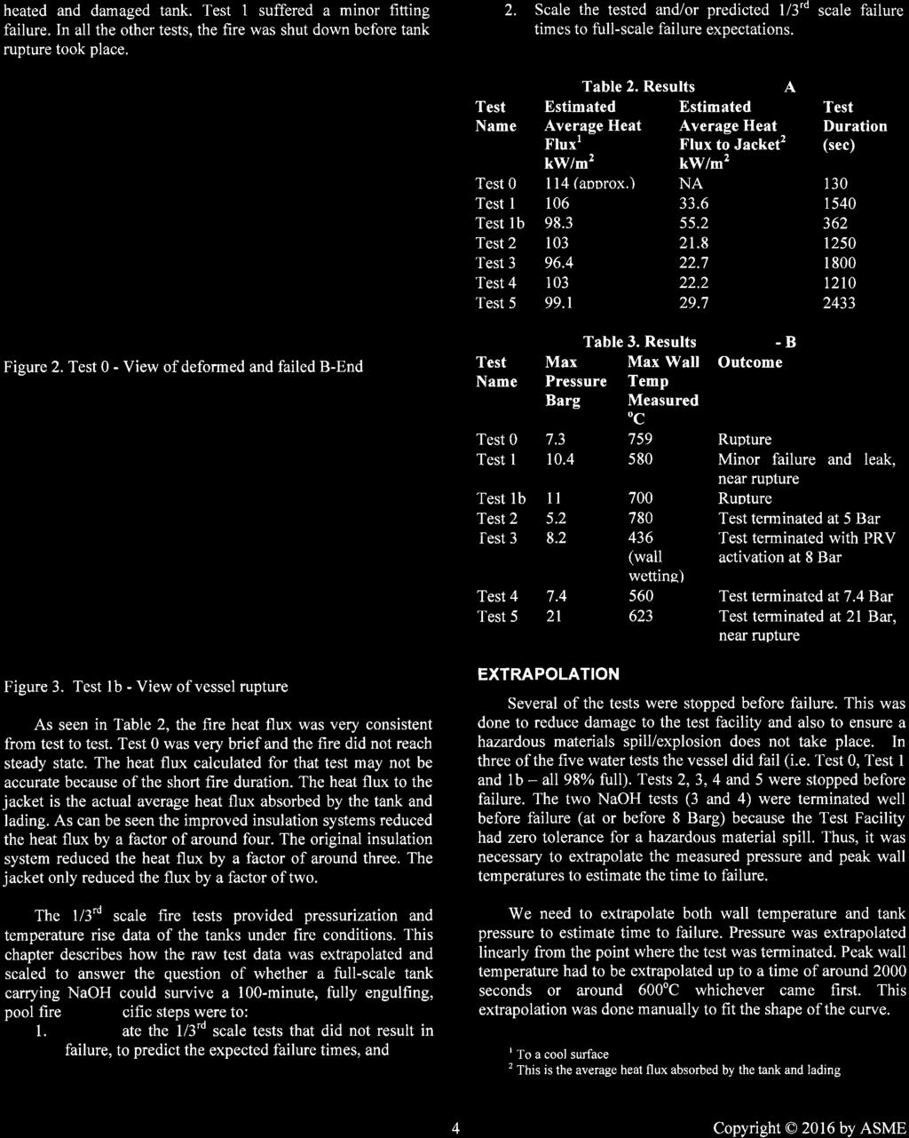
69
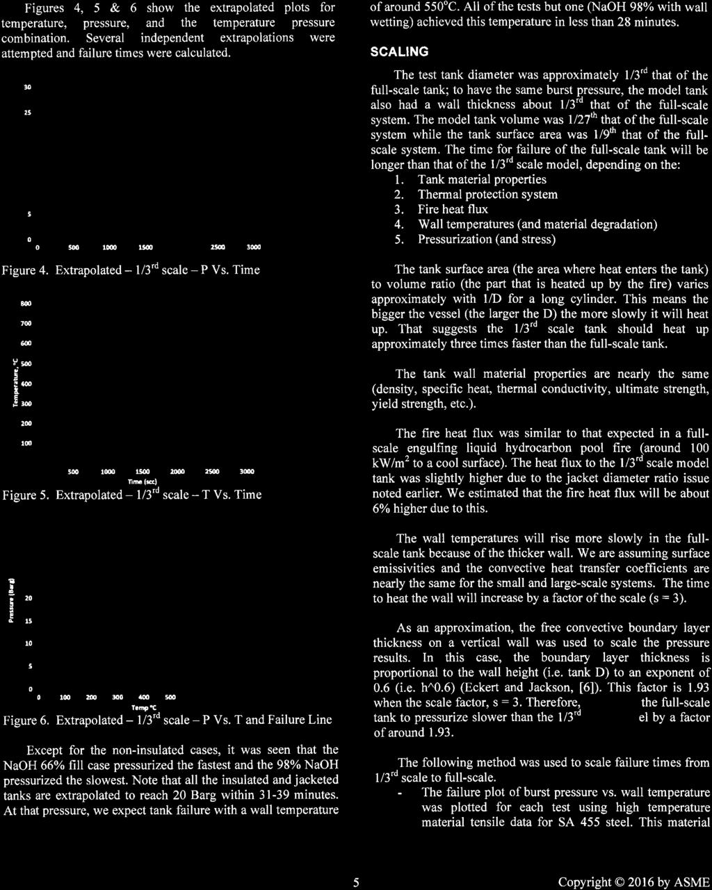

70
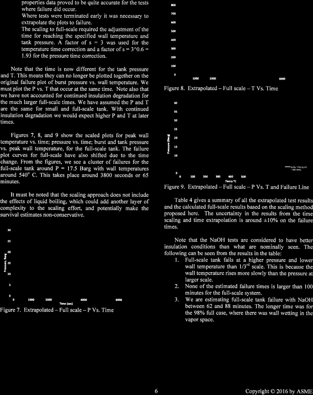
71
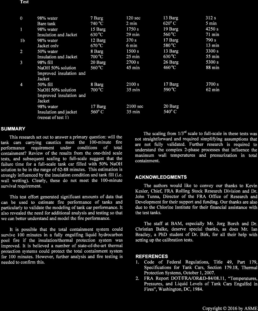

72
73
74
75
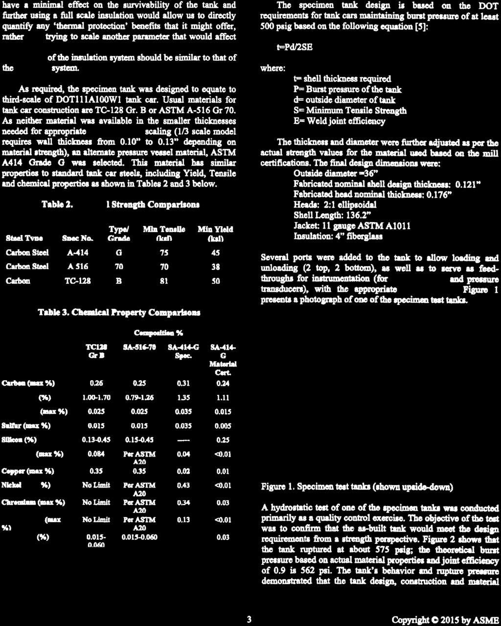
76
77

78
79
INF.41/Add.1/Rev.1. Economic Commission for Europe Inland Transport Committee
 Economic Commission for Europe Inland Transport Committee Working Party on the Transport of Dangerous Goods INF.41/Add.1/Rev.1 Joint Meeting of the RID Committee of Experts and the Working Party on the
The model of thermal response of Liquefied Petroleum Gas Tanks subjected to accidental heat input
 Economic Commission for Europe Inland Transport Committee Working Party on the Transport of Dangerous Goods Joint Meeting of the RID Committee of Experts and the Working Party on the Transport of Dangerous
Uncertainty in the analysis of the risk of BLEVE Fireball in process plants and in transportation
 Uncertainty in the analysis of the risk of BLEVE Fireball in process plants and in transportation Joaquim Casal Centre for Studies on Technological Risk (CERTEC) EEBE, Universitat Politècnica de Catalunya
Hazardous material transport accidents: analysis of the D.G.A.I.S. database
 Environmental Health Risk II 131 Hazardous material transport accidents: analysis of the D.G.A.I.S. database S. Bonvicini & G. Spadoni Department of Chemical, Mining Engineering and Environmental Technologies,
Practical Modelling & Hazard Assessment of LPG & LNG Spills
 Practical Modelling & Hazard Assessment of LPG & LNG Spills UKELG 3 rd April 2012 Tony Ennis Introduction Refrigerated or pressurised Release scenarios & release rate Vaporisation Gas dispersion Consequences
Joint Meeting of the RID Committee of Experts and the Working Party on the Transport of Dangerous Goods REPORTS OF INFORMAL WORKING GROUPS
 ECONOMIC COMMISSION FOR EUROPE INLAND TRANSPORT COMMITTEE Working Party on the Transport of Dangerous Goods Joint Meeting of the RID Committee of Experts and the Working Party on the Transport of Dangerous
MAHB. INSPECTION Process Hazard Analysis
 Number 5 2016 seveso common MAHB INSPECTION s e r i e s criteria Process Hazard Analysis Major Accident Hazards Bureau Security Technology Assessment Unit This publication of the European community on
Annexure 2: Rapid Risk Assesment RISK ANALYSIS
 RISK ANALYSIS (I) Catastrophic Rupture of LPG Bullet Truck (18 MT) At the LPG bottling plant, LPG will be transported by Bullet Truck tank. In the event of fire in LPG bullet truck in parking area, BLEVE
Analysis of the application and sizing of pressure safety valves for fire protection on offshore oil and gas installations Annex I
 Analysis of the application and sizing of pressure safety valves for fire protection on offshore oil and gas installations Annex I Article draft The annex contains an article draft, based on an investigation
A SIMPLIFIED APPROACH TO THE ASSESSMENT OF DOMINO EVENTS CAUSED BY EXTERNAL FIRES
 A SIMPLIFIED APPROACH TO THE ASSESSMENT OF DOMINO EVENTS CAUSED BY EXTERNAL FIRES Gabriele Landucci 1, Gianfilippo Gubinelli 1, Cristiano Nicolella 1 and Valerio Cozzani 2 1 Dipartimento di Ingegneria
Blast Damage Consideratons for Horizontal Pressure Vessel and Potential for Domino Effects
 A publication of CHEMICAL ENGINEERING TRANSACTIONS VOL. 26, 2012 Guest Editors: Valerio Cozzani, Eddy De Rademaeker Copyright 2012, AIDIC Servizi S.r.l., ISBN 978-88-95608-17-4; ISSN 1974-9791 The Italian
State of the Art in the Technical Assessment of DOMINO EFFECT
 State of the Art in the Technical Assessment of DOMINO EFFECT Valerio Cozzani LISES - DICAM, Alma Mater Studiorum - Università di Bologna, Bologna, Italy DOMINO EFFECT: Requirements for the control of
Abstract. 1 Introduction
 Risk assessment study of the mutual interactive influence of working procedures on terminals handling dangerous goods in port of Koper (Slovenia) L. Battelino Water Management Institute, Maritime Engineering
Part 2.5 Dispersion Modeling Using ALOHA
 Part 2.5 Dispersion Modeling Using ALOHA Dr. Arshad Ahmad Email: arshad@utm.my 1 Software Commonly used for Risk Analysis Software SAFETI SFU CAFTAN ETRA HAZSEC. HAZTRAC. PHAST. WHAZAN EFFECTS. DAMAGE
Evaluation of Northwest Citizen Science Initiative (NWCSI) March 7,2015 Report Summary
 March 7,2015 Report Summary") Memo to: Memo No.: 1MIJD63-1/ LLAT Rev 1 Chris Hayes Prepared by: Lindsay Deal Senior Consultant Date: 30 March 2015 Copied to: Eric Dyck, Gail Feltham, Dennis O Mara, Cynthia Reviewed by: Tone Rice Head
Memo to: Memo No.: 1MIJD63-1/ LLAT Rev 1 Chris Hayes Prepared by: Lindsay Deal Senior Consultant Date: 30 March 2015 Copied to: Eric Dyck, Gail Feltham, Dennis O Mara, Cynthia Reviewed by: Tone Rice Head
Road transportation of dangerous goods quantitative risk assessment and route comparison
 Road transportation of dangerous goods quantitative risk assessment and route comparison Philippe Cassini, Nelson Rodrigues To cite this version: Philippe Cassini, Nelson Rodrigues. Road transportation
Identification and Screening of Scenarios for LOPA. Ken First Dow Chemical Company Midland, MI
 Identification and Screening of Scenarios for LOPA Ken First Dow Chemical Company Midland, MI 1 Layers of Protection Analysis (LOPA) LOPA is a semi-quantitative tool for analyzing and assessing risk. The
Process Equipment Exposed to Fire. A Case Study on the Behaviour of a Fire Exposed LNG Segment.
 Process Equipment Exposed to Fire. A Case Study on the Behaviour of a Fire Exposed LNG Segment. Arve Klavenes and Geir Berge Petrell AS Kjøpmannsgata 19, NO-713 Trondheim, Norway When pressurized equipment
USE OF THE EXCEEDANCE CURVE APPROACH IN OCCUPIED BUILDING RISK ASSESSMENT
 USE OF THE EXCEEDANCE CURVE APPROACH IN OCCUPIED BUILDING RISK ASSESSMENT Kieran J Glynn, Advisor Major Accident Risk, BP, UK The exceedance curve approach was developed following the issue of the 2003
Improving Accuracy of Frequency Estimation of Major Vapor Cloud Explosions for Evaluating Control Room Location through Quantitative Risk Assessment
 Improving Accuracy of Frequency Estimation of Major Vapor Cloud Explosions for Evaluating Control Room Location through Quantitative Risk Assessment Naser Badri 1, Farshad Nourai 2 and Davod Rashtchian
INHERENTLY SAFER DESIGN CASE STUDY OF RAPID BLOW DOWN ON OFFSHORE PLATFORM
 INHERENTLY SAFER DESIGN CASE STUDY OF RAPID BLOW DOWN ON OFFSHORE PLATFORM Volton Edwards bptt Angus Lyon DNV Energy Alastair Bird DNV Energy INTRODUCTION A term now in common usage within the oil & gas
ST/SG/AC.10/C.3/2016/8. Secretariat. United Nations. Transport of gas tanks for motor vehicles. Introduction
 United Nations Secretariat Distr.: General 29 March 2016 ST/SG/AC.10/C.3/2016/8 Original: English Committee of Experts on the Transport of Dangerous Goods and on the Globally Harmonized System of Classification
There are three fuelling systems which use LNG/CNG and which may be found in vehicles today:
 UKRO Humberside Education Workshop 2017 NATURAL GAS POWERED VEHICLES Some LGV manufacturers (currently IVECO and SCANIA) are able to offer and Alternative Fueled vehicles that use Compresses Natural Gas
NEW IGC CODE AND IGF CODE
 NEW IGC CODE AND IGF CODE SAFETY ASPECTS Raffaele Piciocchi Gas Center - Greece SAFETY4SEAS - Athens 1 October 2014 Content NEW IGC CODE DRAFT IGF CODE 2 The New IGC Code A new IGC Code has been approved
EXPLOSIVE ATMOSPHERES - CLASSIFICATION OF HAZARDOUS AREAS (ZONING) AND SELECTION OF EQUIPMENT
 AND SELECTION OF EQUIPMENT") EXPLOSIVE ATMOSPHERES - CLASSIFICATION OF HAZARDOUS AREAS (ZONING) AND SELECTION OF EQUIPMENT OVERVIEW ASSESSING THE RISK RELATIONSHIP BETWEEN FIRES AND EXPLOSIONS CLASSIFYING HAZARDOUS AREAS INTO ZONES
EXPLOSIVE ATMOSPHERES - CLASSIFICATION OF HAZARDOUS AREAS (ZONING) AND SELECTION OF EQUIPMENT OVERVIEW ASSESSING THE RISK RELATIONSHIP BETWEEN FIRES AND EXPLOSIONS CLASSIFYING HAZARDOUS AREAS INTO ZONES
Thermodynamic aspects of an LNG tank in fire and experimental validation
 Thermodynamic aspects of an LNG tank in fire and experimental validation Corina Hulsbosch-Dam *, Bilim Atli-Veltin, Jerry Kamperveen, Han Velthuis, Johan Reinders, Mark Spruijt and Lex Vredeveldt TNO,
WP2 Fire test for toxicity of fire effluents
 Pagina 3 di 89 TRA SFEU VTT 22.6.2009 v.2 WP2 Fire test for toxicity of fire effluents Task 2.1.2 Development of small-scale test method for fire effluents Step 1: Use of modeling Plans according to DoW:
Explosion of a road tanker containing liquified natural gas
 Journal of Loss Prevention in the Process Industries 17 (2004) 315 321 www.elsevier.com/locate/jlp Explosion of a road tanker containing liquified natural gas Eulàlia Planas-Cuchi a,,núria Gasulla b, Albert
STATISTICAL SUMMARY RAILWAY OCCURRENCES 2015
 STATISTICAL SUMMARY RAILWAY OCCURRENCES 215 April 216 Transportation Safety Board of Canada Place du Centre 2 Promenade du Portage, 4th floor Gatineau QC K1A 1K8 819-994-3741 1-8-387-3557 www.tsb.gc.ca
Barrier Development and Evaluation Methodology. D.S. Musgrave 1 1 Thermal Visions, Inc., Granville, USA
 Barrier Development and Evaluation Methodology D.S. Musgrave 1 1 Thermal Visions, Inc., Granville, USA 1. Introduction: Vacuum insulation is now a rapidly expanding market and technical advances are being
LP-GAS BLEVES RESULT IN FIRE FIGHTER FATALITIES
 LP-GAS BLEVES RESULT IN FIRE FIGHTER FATALITIES National Fire Protection Association Fire Investigations Albert City, Iowa / Burnside, Illinois / Ste. Elisabeth de Warwick, Quebec, Canada http://ncsp.tamu.edu/reports/nfpa/vapor_explosion.htm
Transport of gas tanks for motor vehicles
 Committee of Experts on the Transport of Dangerous Goods and on the Globally Harmonized System of Classification and Labelling of Chemicals Transport of gas tanks for motor vehicles Submitted by the expert
Transport of gas tanks for motor vehicles
 United Nations Secretariat ST/SG/AC.10/C.3/2016/51 Distr.: General 30 August 2016 Original: English Committee of Experts on the Transport of Dangerous Goods and on the Globally Harmonized System of Classification
THE SIGNIFICANCE OF HAZARD ENDPOINTS IN QUANTITATIVE RISK ANALYSIS
 THE SIGNIFICANCE OF HAZARD ENDPOINTS IN QUANTITATIVE RISK ANALYSIS John B. Cornwell and Jeffrey D. Marx Presented At 6 Process Plant Safety Symposium Houston, Texas April -2, 6 Presented By Quest Consultants
Informal document regarding progress of CEN standards for reference in RID/ADR
 Joint Meeting of the RID Safety Committee and the Working Party on the Transport of Dangerous Goods (Berne, 13-24 March 2000) Informal document regarding progress of CEN standards for reference in RID/ADR
Analysis of Methodologies and Uncertainties in the Prediction of BLEVE Blast
 541 A publication of VOL. 36, 2014 CHEMICAL ENGINEERING TRANSACTIONS Guest Editors: Valerio Cozzani, Eddy de Rademaeker Copyright 2014, AIDIC Servizi S.r.l., ISBN 978-88-95608-27-3; ISSN 2283-9216 The
METHODS TO PREVENT THE PREMATURE ACTIVATION OF RELIEF DEVICES ON TRANSPORT TANKS
 METHODS TO PREVENT THE PREMATURE ACTIVATION OF RELIEF DEVICES ON TRANSPORT TANKS IGC Doc 184/14/E EUROPEAN INDUSTRIAL GASES ASSOCIATION AISBL AVENUE DES ARTS 3-5 B 1210 BRUSSELS Tel: +32 2 217 70 98 Fax:
Drum / cylinder handling
 Page 1 of 8 Drum / cylinder handling This Technical Measures Document covers the storage and handling of toxic and flammable substances in drums and cylinders and refers to relevant codes of practice and
On the protection of process equipment from fire exposure. A study on the effect of different means of protection.
 On the protection of process equipment from fire exposure. A study on the effect of different means of protection. Geir Berge Petrell as www.petrell.no Kjøpmannsgt. 19 N-713 Trondheim, Norway Fire in process
Experimental Study of Hydrogen Release Accidents in a Vehicle Garage
 Experimental Study of Hydrogen Release Accidents in a Vehicle Garage Erik Merilo Mark Groethe James Colton Seiki Chiba Poulter Laboratory SRI International 3rd International Conference on Hydrogen Safety
NEAR FIELD EFFECTS OF SMALL SCALE WATER BLEVE
 Safety and Security Engineering VII 465 NEAR FIELD EFFECTS OF SMALL SCALE WATER BLEVE ROLAND EYSSETTE 2, FREDERIC HEYMES 1, JAMES CRAWFORD 2 & ALBRECHT M. BIRK 2 1 Ecole des Mines d Alès, LGEI/ISR, France
Hazard Operability Analysis
 Hazard Operability Analysis Politecnico di Milano Dipartimento di Energia HAZOP Qualitative Deductive (search for causes) Inductive (consequence analysis) AIM: Identification of possible process anomalies
The Science of Quantitative Risk Assessment for Explosives Safety
 The Science of Quantitative Risk Assessment for Explosives Safety By John Tatom (Manager, Explosives Safety Group, A-P-T Research, Inc. Quantitative risk assessment (QRA) tools, as described in the QRA
A quantitative risk analysis method for the natural gas pipeline network
 PI-195 A quantitative risk analysis method for the natural gas pipeline network Y.-D. Jo1, K.-S. Park1, H.-S. Kim1, J.-J. Kim1, J.-Y. Kim2 & J. W. Ko3 1 Institute of Gas Safety Technology, Korea Gas Safety
Impact on People. A minor injury with no permanent health damage
 Practical Experience of applying Layer of Protection Analysis For Safety Instrumented Systems (SIS) to comply with IEC 61511. Richard Gowland. Director European Process Safety Centre. (Rtgowland@aol.com,
Process Safety Management Of Highly Hazardous Chemicals OSHA 29 CFR
 Process Safety Management Of Highly Hazardous Chemicals OSHA 29 CFR 1910.119 PSM - Definition Not all refining hazards are caused by the same factors or involve ve the same degree of potential damage.
Analysis and Comparison of Calculation Methods for Physical Explosions of Compressed Gases
 133 A publication of VOL. 32, 13 CHEMICAL ENGINEERING TRANSACTIONS Chief Editors: Sauro Pierucci, Jiří J. Klemeš Copyright 13, AIDIC Servizi S.r.l., ISBN 978-88-9568-23-5; ISSN 1974-9791 The Italian Association
Steam generator tube rupture analysis using dynamic simulation
 Steam generator tube rupture analysis using dynamic simulation Heat Exchangers are used to transfer heat from a hot fluid to a cold fluid. Most of the times these fluids are available at different pressures
PROTEGO Braunschweiger Flammenfilter GmbH
 PROTEGO Braunschweiger Flammenfilter GmbH Venting of atmospheric and low-pressure storage tanks ISO 28300/API 2000 Simon Maier Regional Manger Europe 7.12.2017 Agenda 1 Why conservation vents do not function
Using Consequence Modeling to Help Make Emergency Decisions
 Using Consequence Modeling to Help Make Emergency Decisions Della Wong / Nova Chemicals & Robert B. Gerow / SAFER-ERMC CSChE 2002 Conference October 20-23, 23, 2002 Vancouver B.C. If auto safety was like
HANDBOOK SAFETY DEVICES. Ed SAFETY DEVICES DS-ED 01/ ENG 1
 HANDBOOK Ed. 2017 1 CHAPTER 5 SELECTION CRITERIA FOR SAFETY VALVES CALCULATION OF THE DISCHARGE CAPACITY (Ref. EN 13136:2013) The evaluation of the minimum required discharge capacity of safety valves
Fire and Safety for Offshore drilling and production Ajey Walavalkar ANSYS Inc.
 Fire and Safety for Offshore drilling and production Ajey Walavalkar ANSYS Inc. 1 ANSYS, Inc. September 12, Fire and safety related applications Gas Dispersion and Ventilation Formation of combustible
Economic and Social Council
 United Nations Economic and Social Council Distr.: General 21 December 2017 Original: English Economic Commission for Europe Inland Transport Committee Working Party on the Transport of Dangerous Goods
Modelling Hazardous Consequences of a Shale Gas Well Blowout
 Modelling Hazardous Consequences of a Shale Gas Well Blowout Sergey Martynov & Haroun Mahgerefteh (UCL) ShaleX Dissemination Event Texas A&M, Doha, Qatar 18 March 2018 1 Presentation Scope Motivation and
I. CHEM. E. SYMPOSIUM SERIES NO. 85
 FIRE SURVIVAL OF PROCESS VESSELS CONTAINING GAS J. Nylund * The present work is a theoretical evaluation of the ability of process vessels to survive hydrocarbon fires when the vessels are designed and
Challenges in Relief Design for Pilot Plants
 Challenges in Relief Design for Pilot Plants Published on July 5, 2017 Michael Trainor Relief system design at the pilot scale presents unique challenges that don t always apply at the commercial scale.
ISO INTERNATIONAL STANDARD. Small craft Liquefied petroleum gas (LPG) systems
 systems") INTERNATIONAL STANDARD ISO 10239 Second edition 2008-02-15 Small craft Liquefied petroleum gas (LPG) systems Petits navires Installations alimentées en gaz de pétrole liquéfiés (GPL) Reference number ISO
INTERNATIONAL STANDARD ISO 10239 Second edition 2008-02-15 Small craft Liquefied petroleum gas (LPG) systems Petits navires Installations alimentées en gaz de pétrole liquéfiés (GPL) Reference number ISO
Capacity and pressure similar to R-507. Flooded systems. Low temperature (-46.7 C). R22 replacement as long as the condenser has the right size.
. R22 replacement as long as the condenser has the right size.") TECHNICAL DATA SHEET R-428A () Features and uses of R-428A () R-428A (RS-45) is a non flammable azeotropic blend, with zero ODP, compatible with traditional mineral lubricants, alkyl benzene and also with
TECHNICAL DATA SHEET R-428A () Features and uses of R-428A () R-428A (RS-45) is a non flammable azeotropic blend, with zero ODP, compatible with traditional mineral lubricants, alkyl benzene and also with
Addendum 4 Levels of Response
 Addendum 4 Levels of Response Levels of Response to a Hazardous Materials Incident A. Criteria for Categorization Hazardous materials incidents are categorized as Level I, II, or III depending on the severity
Economic and Social Council
 United Nations Economic and Social Council ECE/TRANS/WP.15/AC.1/130/Add.1 Distr.: General 24 April 2013 Original: English Economic Commission for Europe Inland Transport Committee Working Party on the
EGIG. European Gas Pipeline Incident data Group. Dick van den Brand Co-ordinator (external) safety Gasunie, the Netherlands Projectmanager EGIG
 safety Gasunie, the Netherlands Projectmanager EGIG") European Gas Pipeline Incident data Group EGIG Dick van den Brand Co-ordinator (external) safety Gasunie, the Netherlands Projectmanager EGIG IGU, AMSTERDAM June 6th, 2006 1 Contents of this presentation
European Gas Pipeline Incident data Group EGIG Dick van den Brand Co-ordinator (external) safety Gasunie, the Netherlands Projectmanager EGIG IGU, AMSTERDAM June 6th, 2006 1 Contents of this presentation
BASF Flash Fire FRC Assessment Tool
 BASF Flash Fire FRC Assessment Tool Introduction The assessment tool offered in this document was developed to assist BASF manufacturing units in evaluating the potential for flash fire occurrence and
LPG TANK INFORMATION An energy company that puts
 LPG TANK INFORMATION An energy company that puts Safety first. LPG TANKS Thanks Thank you for choosing Kleenheat for your LPG supply. We consider safety our number one priority, so please make time to
The Application Of Computer Modeling To Improve The Integrity Of Ballast Tanks
 Paper No. 4255 The Application Of Computer Modeling To Improve The Integrity Of Ballast Tanks Robert Adey, Guy Bishop, John Baynham, CM BEASY Ltd Ashurst Lodge Southampton, SO40 7AA, UK ABSTRACT Generally
PRAGMATIC ASSESSMENT OF EXPLOSION RISKS TO THE CONTROL ROOM BUILDING OF A VINYL CHLORIDE PLANT
 PRAGMATIC ASSESSMENT OF EXPLOSION RISKS TO THE CONTROL ROOM BUILDING OF A VINYL CHLORIDE PLANT L.P. Sluijs 1, B.J. Haitsma 1 and P. Beaufort 2 1 Vectra Group Ltd. 2 Shin-Etsu (contact details: Vectra Group
CONCLUSIONS AND RECOMMENDATIONS
 CHAPTER 5: CONCLUSIONS AND RECOMMENDATIONS 5.1 General This chapter presents the conclusions and main recommendations flowing from the analysis of level crossing systems and safety performance in several
SELECTION CRITERIA FOR SAFETY VALVE
 mdmdmdpag 1 di 17 SELECTION CRITERIA FOR SAFETY VALVE CALCULATION OF THE DISCHARGE CAPACITY (Ref. EN 13136:2013) The calculation of the minimum discharge capacity is linked to the system configuration
Notice for Pressure Special Equipment Manufacture Licensing
 AQSIQ Notice No.151 (2012) Notice for Pressure Special Equipment Manufacture Licensing To further enhance the implementation of the manufacture licensing system to imported pressure special equipment,
SAFETY BARRIER PERFORMANCE ASSESSMENT
 SAFETY BARRIER PERFORMACE ASSESSMET I THE FRAMEWORK OF ESCALATIO GABRIELE LADUCCI Dipartimento di Ingegneria Civile e Industriale, Università di Pisa, Largo Lucio Lazzarino 1, 56126 Pisa, Italy gabriele.landucci@diccism.unipi.it
INTERNATIONAL ASSOCIATION OF CLASSIFICATION SOCIETIES. Interpretations of the. IGF Code
 INTERNATIONAL ASSOCIATION OF CLASSIFICATION SOCIETIES s of the IGF Code CONTENTS GF1 Test for gas fuel tank s high level alarm Rev.1 July 2017 GF2 Ship Steel Protection against Liquefied Gas Fuel (Part
Developing a Policy for Auto Transportation of Medical Oxygen in High Pressure Cylinders and Cryogenic Vessels
 Developing a Policy for Auto Transportation of Medical Oxygen in High Pressure Cylinders and Cryogenic Vessels Since 1993, Applied Home Healthcare Equipment LLC has published numerous publications, videos,
PURE SUBSTANCE. Nitrogen and gaseous air are pure substances.
 CLASS Third Units PURE SUBSTANCE Pure substance: A substance that has a fixed chemical composition throughout. Air is a mixture of several gases, but it is considered to be a pure substance. Nitrogen and
API Standard Venting Atmospheric and Low-Pressure Storage Tanks: Nonrefrigerated and Refrigerated
 General API Standard 2000 - Venting Atmospheric and Low-Pressure Storage Tanks: Is there any limit for the maximum allowable linear velocity or any other parameter for the roof of a floating roof tank
MICROSCOPIC ROAD SAFETY COMPARISON BETWEEN CANADIAN AND SWEDISH ROUNDABOUT DRIVER BEHAVIOUR
 MICROSCOPIC ROAD SAFETY COMPARISON BETWEEN CANADIAN AND SWEDISH ROUNDABOUT DRIVER BEHAVIOUR Canadian Association of Road Safety Professionals Conference 2017 Paul St-Aubin, Ph.D. 1,2,3, Nicolas Saunier,
Laboratory Hardware. Custom Gas Chromatography Solutions WASSON - ECE INSTRUMENTATION. Custom solutions for your analytical needs.
 Laboratory Hardware Custom Gas Chromatography Solutions Custom solutions for your analytical needs. Laboratory Hardware Wasson-ECE Instrumentation offers hardware-only solutions for advanced chromatography
Information on work in progress in CEN
 Economic Commission for Europe Inland Transport Committee Working Party on the Transport of Dangerous Goods Joint Meeting of the RID Committee of Experts and the Working Party on the Transport of Dangerous
HOW TO MANAGE VAPORIZATION IN AN ANALYTICAL SYSTEM By Dean Slejko and Tony Waters
 HOW TO MANAGE VAPORIZATION IN AN ANALYTICAL SYSTEM By Dean Slejko and Tony Waters If the analyzer in your analytical system requires gas but your sample is liquid, the only option is to convert the liquid
Technical Standards and Legislation: Risk Based Inspection. Presenter: Pierre Swart
 Technical Standards and Legislation: Risk Based Inspection Presenter: Pierre Swart Agenda Change in Legislation. Where RBI fits in. Application to implement RBI. RBI concepts. Elements of an RBI analysis.
Laboratory Hardware. Custom Gas Chromatography Solutions WASSON - ECE INSTRUMENTATION. Engineered Solutions, Guaranteed Results.
 Laboratory Hardware Custom Gas Chromatography Solutions Engineered Solutions, Guaranteed Results. WASSON - ECE INSTRUMENTATION Laboratory Hardware Wasson-ECE Instrumentation offers hardware-only solutions
3 rd Year Design Module Scope
 LOSS PREVENTION & Process Safety PROCESS HAZARDS ANALYSIS -3 rd Year Design Module - 3 rd Year Design Module Scope Hazard Identification In the Process 1. Identify the major hazards that are present 2.
Safety in Petroleum Industry
 Chemical ( Industrial ) Disaster Management Conference, Bangalore 30 January 2014 Safety in Petroleum Industry Refineries and Petrochemical plants are highly energyintensive Handle highly inflammable and
Cylinder Exchange Training Manual
 Cylinder Exchange Training Manual This manual and training program is provided by Root Enterprises, Inc. (Class 1) Revised 07/11 1 Table of Contents: 1. Description and Characteristics of Propane. 2. Cylinders
CNS In-Pool Assembly Mechanical Design for OYSTER Project
 CNS In-Pool Assembly Mechanical Design for OYSTER Project JINBOK CHOI, JUNGHYUN RYU Korea Atomic Energy Research Institute (KAERI) 111 Deadeok-daero 989Beon-gil, Yuseong-gu, Daejeon, Republic of Korea
44 (0) E:
 E:") FluidFlow Relief Valve Sizing Handbook Flite Software 2016 Flite Software N.I. Ltd, Block E, Balliniska Business Park, Springtown Rd, Derry, BT48 0LY, N. Ireland. T: 44 (0) 2871 279227 E: sales@fluidflowinfo.com
FluidFlow Relief Valve Sizing Handbook Flite Software 2016 Flite Software N.I. Ltd, Block E, Balliniska Business Park, Springtown Rd, Derry, BT48 0LY, N. Ireland. T: 44 (0) 2871 279227 E: sales@fluidflowinfo.com
Using LOPA for Other Applications
 10 Using LOPA for Other Applications 10.1. Purpose LOPA is a tool used to perform risk assessments. Previous chapters described its use in assessing the risk level of process hazards scenarios and in evaluating
Flammable Environments Guideline
 GUIDE Flammable Environments Guideline 2014-0004 The Canadian Association of Petroleum Producers (CAPP) represents companies, large and small, that explore for, develop and produce natural gas and crude
DIGITAL SOLUTIONS TRAINING CATALOGUE. QRA and CFD simulation. Phast, Safeti and KFX SAFER, SMARTER, GREENER
 DIGITAL SOLUTIONS TRAINING CATALOGUE QRA and CFD simulation Phast, Safeti and KFX SAFER, SMARTER, GREENER 02 PHAST, SAFETI AND KFX Training catalogue Global training Our increased focus on global training,
Liquefied gas cargo tanks and process pressure vessels
 .1 -.3 Liquefied gas cargo tanks and process pressure vessels.1 General.1.1 The present texts give the general principles which are applied by Classification Societies for approval and survey of the relevant
Fitness for Service Assessment of Ageing Pressure Vessel Experiencing External Corrosion: A Case Study
 The International Journal Of Engineering And Science (IJES) Volume 6 Issue 2 Pages PP 12-16 2017 ISSN (e): 2319 1813 ISSN (p): 2319 1805 Fitness for Service Assessment of Ageing Pressure Vessel Experiencing
Numerical and Experimental Investigation of the Possibility of Forming the Wake Flow of Large Ships by Using the Vortex Generators
 Second International Symposium on Marine Propulsors smp 11, Hamburg, Germany, June 2011 Numerical and Experimental Investigation of the Possibility of Forming the Wake Flow of Large Ships by Using the
Define Hazardous Materials. Hazardous Materials Awareness. Hazardous Materials Incidents. Public Safety Duty to Act. Five Levels of Training
 Define Hazardous Materials Hazardous Materials Awareness A hazardous materialis any item or agent (biological, chemical, physical) which has the potential to cause harm to humans, animals, or the environment,
AN INVESTIGATION OF LONGITUDINAL VENTILATION FOR SHORT ROAD TUNNELS WITH HIGH FIRE HRR
 - 9 - AN INVESTIGATION OF LONGITUDINAL VENTILATION FOR SHORT ROAD TUNNELS WITH HIGH FIRE HRR O Gorman S., Nuttall R., Purchase A. Parsons Brinckerhoff, Australia ABSTRACT Recent fire tests for tunnels
Prepared by a Joint Working Group of the International DME Association and the World LP Gas Association
 Recommendations for the Blending of Dimethyl Ether (DME) with Liquefied Petroleum Gas (LPG) for Commercial, Household, and Industrial Cooking and Heating Applications Prepared by a Joint Working Group
Queue analysis for the toll station of the Öresund fixed link. Pontus Matstoms *
 Queue analysis for the toll station of the Öresund fixed link Pontus Matstoms * Abstract A new simulation model for queue and capacity analysis of a toll station is presented. The model and its software
APPENDIX A: SENSITIVITY TESTS INPUTS AND SETUP TABLES
 APPENDIX A: SENSITIVITY TESTS INPUTS AND SETUP TABLES This appendix contains two tables for each case and model; the first outlines the assumptions and inputs that were kept constant for each case, and
II. Table C, column 20, additional requirement number 12 for UN 1280 and UN 2983: Table C column 20 mentions additional requirement/remark #12:
 Economic Commission for Europe Inland Transport Committee Working Party on the Transport of Dangerous Goods Joint Meeting of Experts on the Regulations annexed to the European Agreement concerning the
THE BEHAVIOUR OF TANKS ENGULFED IN FIRE - THE DEVELOPMENT OF A COMPUTER PROGRAM. D L M Hunt* and P K Ramskill*
 THE BEHAVIOUR OF TANKS ENGULFED IN FIRE - THE DEVELOPMENT OF A COMPUTER PROGRAM D L M Hunt* and P K Ramskill* A computer code has been written to predict temperatures and pressure within a tank, partly
Responding to Natural Gas Pipeline Emergencies
 Responding to Natural Gas Pipeline Emergencies Who is Florida Gas Transmission? Florida Gas Transmission operates nearly 5,000-miles of interstate natural gas transmission pipelines, a system that extends
Hazardous Materials Management Guidelines
 Environmental, Health and Safety Guidelines Hazardous Materials Management Guidelines Applicability These guidelines apply to facilities and activities involving the transportation, production, handling,
REPUBLIC OF KENYA MINISTRY OF TRANSPORT AND COMMUNICATIONS CIVIL AIRCRAFT ACCIDENT REPORT TRANSWORLD SAFARIS KENYA LIMITED
 REPUBLIC OF KENYA MINISTRY OF TRANSPORT AND COMMUNICATIONS CIVIL AIRCRAFT ACCIDENT REPORT CAV/ACC /6/00 OPERATOR: AIRCRAFT: REGISTRATION: PLACE: TRANSWORLD SAFARIS KENYA LIMITED LINDSTRAND LBL 260A BALLOON