INSTALLATION MANUAL Residential and Small Commercial Applications
|
|
|
- Lester Randall
- 6 years ago
- Views:
Transcription


1 INSTALLATION MANUAL Residential and Small Commercial Applications
2
3 WATERTEC S100 INSTALLATION MANUAL Congratulations on selecting the WaterTec S100 kit, the industry s leading soil-moisture sensing unit for residential and small commercial applications. The following manual will guide you step-by-step through the installation process. Pages contain troubleshooting steps to further assist in your installation. Additional information can be found online at Before You Get Started...3 S100 Operational Features...4 Step 1 - bisensor Placement...5 Step 2 - Determining Your Wiring Configuration...6 Option A - Valve Common Interrupter...6 Option B - Drip Bypass...6 Step 3 - Install and Wire S Step 4 - Setup Sprinkler Timer and Set Cycle Window...7 Step 5 - Connect the bisensor...7 Step 6 - bisensor Installation...8 Step 7 - Verify All Connections...9 Step 8-24-hour Moisture Threshold Calibration...9 Future Adjustments...10 How to Get a Beautiful Lawn...10 Troubleshooting for Initial Installation Operational Troubleshooting & Adjustments...12 Troubleshooting Lawn Conditions Troubleshooting Error Codes...17 Before You Get Started Read the entire manual before starting Before installing your new WaterTec S100, operate the sprinkler system to ensure the system is functioning properly and all heads are properly adjusted. For best results you will need to know the distribution rate of your sprinklers as this usually varies greatly from zone to zone. Ideally each zone would receive the same amount of water (1/2 to 3/4 ). Baseline recommends that, prior to installation, you replace any back-up batteries your timer requires. You may need to refer to the original owner s manual. WaterTec S100 Manual Aug06 Rev. 1 (866) Copyright 2006, Baseline, LLC All Rights Reserved WaterTec, bisensor and biline are trademarks of Baseline, LLC. 3
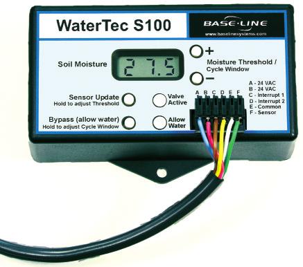
4 A Soil Moisture Sensor Update Hold to adjust Threshold Bypass (allow water) Hold to adjust Cycle Window B C F G D Valve Active Allow Water E + Moisture Threshold/ Cycle Window - A B C D E F H A - 24 VAC B - 24 VAC C - Interrupt 1 D - Interrupt 2 E - Common F - Sensor Operational Features A B C D E F G H Soil Moisture: Water content present in the soil Value is displayed by default when no buttons are pressed or held. Soil moisture level is displayed as volumetric, ranging from 0.0 to Sensor Update: Brief button press: Causes the bisensor to take a moisture reading. Hold button: Displays current Moisture Threshold value. See below for operation. Bypass: Allows the sprinkler timer to operate without interruption from the S100. Bypass mode is indicated by a periodic flashing of OFF on the S100 display. Brief button press: Toggle the Bypass function. When enabled the Allow Water light should turn on. Hold button: Holding the Bypass button for 2 seconds displays the current Cycle Window duration. Use (+)/(-) buttons while holding Bypass to change the Cycle Window to a value between 0 and 24 hours. Default is 12 hours. Moisture Threshold: Soil moisture value at which the S100 will allow watering. While Sensor Update button is being held, use (+)/(-) buttons to change the moisture threshold. Cycle Window: The cycle window is the time allowed to complete a water cycle once your soil moisture has reached your soil moisture threshold. Valve Active: This light indicates that the valve the bisensor is attached to is currently active (watering). Allow Water: This light indicates that the S100 is allowing your sprinkler timer to water based upon its user defined settings (the system will begin watering at the next start time programmed on the sprinkler timer). Wire Harness: Wires are attached from the sprinkler timer to the S100 here. Setup Operations: Calibration Cycle (for initial installation or bisensor repositioning) Hold the (+)(-) and (Bypass) buttons simultaneously for 3 seconds. The screen will flash between CAL 24 H and the current moisture reading. The 24 H will count down on the hour until the calibration is complete. Watering is paused during this time. Communication Test: The S100 communicates with the bisensor for about two minutes, checking for any potential errors. Hold the (+)(-) and (Sensor Update) buttons simultaneously for 3 seconds. For more information, see Step 1 on page 15 in the Troubleshooting section. 4 WaterTec S100 Manual Aug06 Rev. 1


5 Step 1 bisensor Placement When planning the bisensor location, take into account variables such as distribution rate, sun exposure and soil type, or other site specific characteristics that may affect water holding capacity or the rate at which plants use water. The location of the bisensor will determine how frequently your sprinkler system is allowed to water. If the bisensor is placed in an area that is generally wetter than average it will cause your system to operate less frequently, possibly causing dry spots. If the bisensor is placed in an area that receives less than average water it will cause the system to operate more frequently. Baseline bisensor placement recommendations: Place the bisensor near the center of a zone (should only receive water from one zone). Place the bisensor in an area that receives average to slightly below average water. Keep away from sidewalks and driveways to avoid water from car washing or other factors. The illustration to the right identifies heavy shadow and runoff areas in Red and ideal locations in Light Green. Avoid Red areas when installing your bisensor. Dark Green areas with some shadow can be used as a secondary location. SENSOR LOCATION SECONDARY LOCATION SENSOR LOCATION SENSOR LOCATION SECONDARY LOCATION SENSOR LOCATION N note Note: When installing the bisensor connect it to the most convenient valve. This connection is used for communication. WaterTec S100 Manual Aug06 Rev. 1 5
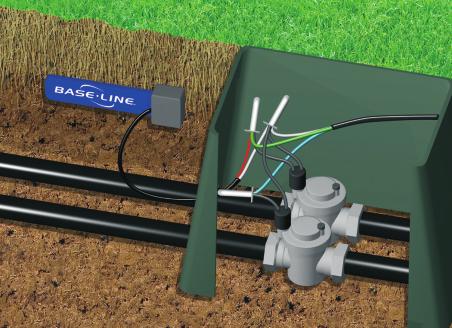
6 Step 2 Determining Your Wiring Configuration Option A: This is the most common option and will work on any timer that has an accessible 24VAC power source. Option B: This option is used for systems with zones requiring more frequent watering than the bisensor controlled zones utilizing Baseline's Drip Bypass. (DRIP BYPASS SOLD SEPARATELY) Option A Valve Common Interrupter Connect wires A and B (red and blue) to the 24V connectors on the sprinkler timer Connect wires C and E (yellow and white) to the common on the sprinkler timer Connect wire D (brown) to the valve common Connect wire F (green) to the valve with the sensor Soil Moisture Sensor Update Hold to adjust Threshold Bypass (allow water) Hold to adjust Cycle Window + A B C D E F Valve Active Allow Water Moisture Threshold/ Cycle Window - A - 24 VAC B - 24 VAC C - Interrupt 1 D - Interrupt 2 E - Common F - Sensor SPRINKLER TIMER 24V COM Connect sensor wires across valve solenoid. Option B Drip Bypass Connect wires A and B (red and blue) to the 24V connectors on the sprinkler timer Connect wires C and E (yellow and white) to the common on the sprinkler timer Connect wire D (brown) to the valve common Connect wire F (green) to the valve with the sensor Soil Moisture Sensor Update Hold to adjust Threshold Bypass (allow water) Hold to adjust Cycle Window + A B C D E F Valve Active Allow Water Moisture Threshold/ Cycle Window - A - 24 VAC B - 24 VAC C - Interrupt 1 D - Interrupt 2 E - Common F - Sensor SPRINKLER TIMER 24V COM Connect sensor wires across valve solenoid. 6 WaterTec S100 Manual Aug06 Rev. 1
7 A B C D E F Step 3 Install and Wire the S Strip the provided harness wire and connect to wire harness as shown: red, blue, yellow, brown, white and green (from left to right). Plug the harness into the S At this point also strip the bisensor wire providing enough exposed wire to connect to desired valve. 3. Mount the S100 near your sprinkler timer. The S100 is not weatherproof. 4. Wire the S100 using the option chosen in Step 2. Using your sprinkler timer, manually run all zones to ensure that the connections are solid. Step 4 Setup Sprinkler Timer and Set Cycle Window 1. Set your sprinkler timer to apply 1/2 to 3/4 of water to each zone each day. This will allow the in-ground moisture bisensor to choose the best possible days to water. For instructions on how to check distribution rate, see SPRINKLER TIMER SEN 24V COM Step 2 on page 15 of the Troubleshooting section. (If needed, refer to the sprinkler timer s manual for operational instructions). 2. The cycle window is the time allowed to complete a water cycle once your soil moisture has reached your moisture threshold. The S100 comes preset with a 12 hour window. This works well for most applications and there may be no need to re-set this value. Reasons to re-set the cycle window: If your system needs more than twelve hours to complete a watering cycle once the bisensor zone has been watered. If you choose to water your lawn several times per day (this can result in poor root development). To set the cycle window hold the Bypass button for 2 seconds. This will display the current cycle window. Use (+)/(-) buttons while holding the Bypass button to change the cycle window to a value between 0 and 24 hours. Step 5 Connect the bisensor NOTE: It is very important that you use waterproof connectors after all connections have been verified in Step Before burying the bisensor, verify communications by pressing the Sensor Update button. A numeric reading indicates success. A display of Er1 or Er2 indicates a wiring error. Consult the Troubleshooting section on pages Manually run the station to which you connected the bisensor to verify connection. 3) Once connections have been verified, disconnect the bisensor from the valve as this simplifies burial. Valve Active Allow Water Moisture Threshold/ Cycle Window A - 24 VAC B - 24 VAC C - Interrupt 1 D - Interrupt 2 E - Common F - Sensor WaterTec S100 Manual Aug06 Rev. 1 7

 1.")


8 Step 6 bisensor Installation The bisensor has several burial requirements. There must be good contact between the soil and the bisensor, and it needs to be buried lying on its side. If buried flat, the bisensor readings can be wrong due to moisture pooling on the surface of the bisensor. The bisensor should be buried 4 to 6 inches deep in turf areas and deeper for planters and tree areas (root zones). OPTION A Dig 6 X12 section and... peel back sod with roots intact. note Note: Ensure bisensor is buried 4-6 below grass line for optimal readings. This depth also prevents future damage, i.e., aerators, etc. (Option A) 1. Using a shovel or edger cut out a piece of sod approximately 1-foot long by 6-inches wide in the area where you plan to bury the bisensor. 2. Carefully remove the sod and try to keep the roots intact. 3. Dig a small trench the length of the bisensor in the exposed dirt. 4. Insert the bisensor into the trench, burying it on its long edge. If buried flat, bisensor readings can be wrong due to moisture pooling on surface of the bisensor. 5. Remove any rocks or gravel that are touching the surface of the bisensor to ensure there are no air pockets. 6. Cut a slit back to the valve box for the communication wires. Take care to bury them deep enough to avoid damage from aeration or other activities. 7. Using a bucket of water saturate the soil surrounding the bisensor and compact the soil around it tightly. 8. Refill hole, replace sod and saturate the area thoroughly. Once saturated, compact soil firmly around the bisensor. The bisensor must make good contact with the surrounding soil. Bury bisensor 4 TO 6 deep Re-cover area and heavily saturate with water. OPTION B Cut slit into grass about 12 long by 6 deep... then work shovel back and forth to create a slot for the bisensor Bury bisensor 4 TO 6 deep (Option B) 1. With a flat blade shovel, cut a slit in the grass where the bisensor will be placed. Widen slit with a back and forth motion. 2. Place the bisensor in the slit horizontally so Re-cover area and the top of the bisensor is 4-6 deep. heavily saturate with water. 3. Remove any rocks or gravel that are touching the bisensor to ensure there are no air pockets. 4. Cut a slit back to the valve box for the communication wires. Take care to bury them deep enough to avoid damage from aeration or other activities. 5. Using a bucket of water saturate the soil surrounding the bisensor and compact the soil around it tightly. 8 WaterTec S100 Manual Aug06 Rev. 1
9 note Note: It is critical that the soil is well saturated with water, otherwise the moisture threshold calibration in Step 8 will fail. It is also important that you complete Step 8 within one hour of saturating soil. Step 7 Verify All Connections Reconnect bisensor to desired valve. Verify that all connections are functioning properly after the bisensor has been buried. 1. Verify communications with bisensor by pressing the Sensor Update button. A numeric reading indicates success. A display of Er1 or Er2 indicates a wiring error. Consult the Troubleshooting section on page if you receive an error. 2. If the numeric reading is below 20, the bisensor has excessive air pockets around it. If this occurs, rebury the bisensor as per Step 6 taking extra care to ensure the soil is well compacted around the bisensor. 3. Manually run the station connected to the bisensor. This will verify connection. note Note: All connections need to be water-tight. There are several products on the market that will accomplish this. Follow the manufacturer s instructions for the product you choose. Step 8 24 Hour Moisture Threshold Calibration The S100 comes with an auto-calibration capability that will set the moisture threshold based on your soil type. This is useful for new installations. Before running the moisture threshold calibration; ensure that the soil around the bisensor is heavily saturated with water as instructed in Step 6. If not properly saturated, the calibration will fail. Write down the current date, time and sensor reading to be used as a reference point. Date Time Sensor Reading 1. Hold the (+)(-) and (Bypass) buttons simultaneously for 3 seconds. The screen will flash between CAL 24H and the current moisture reading. The 24H will count down on the hour until the calibration is complete. Watering is paused during this time. It is important that the bisensor does not receive any water during calibration. This process will fail or provide false feedback if it does. 2. If the calibration succeeds, the moisture threshold will be automatically set, and the system will allow watering when soil moisture drops below this threshold. If an error occurs during calibration, the screen will flash Er3 indicating calibration failed, and then another Er#. This # represents the reason for failure. See Troubleshooting for information on the various error messages. The S100 will need to be re-calibrated. In addition, in the event of a failure, the S100 will go into bypass mode allowing for normal timer-based watering. Note: If you need to exit this mode early, hold the Sensor Update button for 3 seconds. note Note: If the bisensor receives water during this 24 hour period, or was not saturated during Step 6, the calibration will either fail entirely or set an incorrect threshold for your lawn. If this happens, you will need to resaturate the soil and restart Step 8. WaterTec S100 Manual Aug06 Rev. 1 9
 by pressing the Sensor Update button.")
10 Future Adjustments Manual Threshold Adjustment As the grass roots grow back around the bisensor, the threshold may need to be adjusted. Observe lawn conditions and then adjust the threshold as needed. To manually adjust your moisture threshold begin by taking a bisensor reading (after a watering cycle) by pressing the Sensor Update button. Next set your threshold slightly above or below this value (An adjustment of points is all that should be necessary). Raising the threshold will result in more frequent watering. Lowering the threshold will result in less frequent watering. Automatic Moisture Threshold Calibration If you need to re-calibrate your moisture threshold, simply begin by re-saturating the ground surrounding the bisensor. The dirt surrounding the bisensor needs to be holding as much water as it can, it may take a few applications of water to accomplish this. Once saturated, repeat Step 8 of this manual to automatically calibrate your moisture threshold. How to Get a Beautiful Lawn Watering SMART is a critical step towards a beautiful and healthy lawn. Water Less Frequently Using the WaterTec to determine which days to water will promote deep roots and will water only when needed, conserving water (and saving you money). Watering too often promotes a shallow root structure and washes nutrients from the roots. Water Deeply Set your sprinkler timer to apply 1/2 to 3/4 of water (determine water application rate for each zone and calculate the run time to apply 3/4 of water use cups or cans to catch water for a fixed time to determine application rate). Each zone could have a different water run time. 10 WaterTec S100 Manual Aug06 Rev. 1
11 Troubleshooting for Initial Installation Problem Cause Solution Er1 is displayed Er2 is displayed Er3 is displayed along with another error Er4 is displayed (this is a warning message, pressing Sensor Update will clear this) Er5 is displayed The S100 cannot communicate with the bisensor The S100 has detected excessive current while trying to communicate with the bisensor There was a problem during the S hour moisture threshold calibration Unexpected reading during 24-hour moisture threshold calibration, final reading was not substantially different from first (please refer to the Er4 code on page 17) An interruption of the 24-hour moisture threshold calibration occurred due to attempted valve activation Er6 is displayed Unexpectedly low reading during 24- hour moisture threshold calibration Display is blank. S100 is not receiving 24 VAC LED s are off Display flashes random segments or 88.8 The S100 common is not connected correctly Check the wiring and connections to the bisensor Make sure the correct valve wire and common wire are used After making repairs follow the Verify bisensor Communication instructions under Step 1 at the end of this section Double-check the wiring and connections to the bisensor Make sure the common and bisensor wires are correctly connected Check for a faulty valve solenoid After making repairs follow the Verify bisensor Communication instructions under Step 1 at the end of this section This error is accompanied by one of the other error codes Refer to the other Er# for possible solutions Follow the instructions under Step 5 at the end of this section Make sure no extra water is applied to the bisensor after calibration starts or the S100 may set a non-optimal threshold Check the valve the bisensor is connected to for proper operation After making repairs follow the instructions under Step 5 at the end of this section (turn off controller during 24-hour moisture threshold calibration) Follow the instructions under Step 5 at the end of this section Make sure the 24VAC transformer is plugged in Check that the two 24VAC lines and the common from the S100 are wired correctly Make sure the common from the S100 is connected to the valve common of the sprinkler controller WaterTec S100 Manual Aug06 Rev. 1 11
12 Troubleshooting for Initial Installation (continued) Problem Cause Solution The S100 flashes "88.8" then fades away bisensor is reading a value under 20 when soil appears wet Controller does not have access to 24VAC The controller sensor ports will not support the S100 There may be air pockets around the bisensor Some older mechanical controllers Use the common interrupt method to wire the S100 Rebury the bisensor as per Step 6 on page 8. When reburying the bisensor be especially careful that there are NO rocks touching the blade of the bisensor as this can lead to false readings Some older sprinkler controllers do not have available access to 24VAC; for more information on this go to Operational Troubleshooting & Adjustments Main Problem Specifics Solution Er1 is displayed Er2 is displayed Display is blank. LED s are off There are puddles forming during irrigation The S100 cannot communicate with the bisensor The S100 has detected excessive current while trying to communicate with the bisensor S100 is not receiving 24 VAC Check the wiring and connections to the bisensor Connections need to be waterproof and free of corrosion Check bisensor wires for damage Check bisensor for damage After making repairs follow the Verify bisensor Communication instructions under Step 1 at the end of this section Double-check the wiring and connections to the bisensor Verify connections inside valve box are water tight Check for a faulty valve solenoid Check for lightning damage Make sure the 24VAC transformer is plugged in and receiving power Check that the two 24VAC lines and the common from the S100 are wired correctly Follow the instructions under Step 6 at the end of this section 12 WaterTec S100 Manual Aug06 Rev. 1

13 Troubleshooting Lawn Conditions Use this diagram in reference to the zones in this Troubleshooting section ZONE 1 ZONE 2 ZONE 3 ZONE 4 Lawn Condition Possible Causes Solution Area around the bisensor is dry but the lawn is wet Area around the bisensor is wet but the lawn is dry Zone 1 is wet, remaining lawn is dry Zone 1 is dry, remaining lawn is wet Zones 1-3 have adequate water, Zone 4 is drying out Plugged head over bisensor Broken or missing head near bisensor Object was placed over the bisensor Broken or leaky head near the bisensor causing water to pool around the bisensor Broken line causing water to leak into the soil surrounding the bisensor Run time on zones 2-4 are too short Cycle window is not long enough Run time on zone 1 is too short Disruption causing the valve to not operate correctly Check the area around the bisensor. Fix any problems with the irrigation system that would cause the area around the bisensor to not receive water. In addition remove any obstructions that may have been placed over where the bisensor is buried Replace or repair parts as needed Check the distribution rate of zones 2-4 as per Step 2 on page 15. Adjust the run time accordingly Check the duration of your cycle window. Refer to Step 4 on page 7 Check the distribution rate of zone 1 as per Step 2 on page 15. Adjust the run time accordingly Check the wiring between the valve box and the valve. Make any necessary repairs WaterTec S100 Manual Aug06 Rev. 1 13
14 Lawn Condition Possible Causes Solution Entire lawn is dry Entire lawn is too wet bisensor is receiving adequate water, other areas are dry bisensor is receiving adequate water, other areas are wet Zones 1, 3 and 4 are receiving adequate water. Zone 2 has dry or wet areas Troubleshooting Lawn Conditions (continued) System Malfunction Run times on all zones are too short Moisture Threshold is too low Heavy rain fall immediately after or during a watering cycle Run times on all zones are too long Moisture Threshold is too high Water distribution is not uniform bisensor is buried in an area that receives above average watering Water distribution is not uniform bisensor is buried in an area that receives significantlly below average watering Water distribution in zone 2 is not uniform Check the overall system functions. Ensure the master valve is operating correctly, that the system is not shut down, etc... Check the distribution rate of all zones as per Step 2 on page 15. Adjust the run times accordingly Refer to Step 7 on page 17 N/A Check the distribution rate of all zones as per Step 2 on page 15. Adjust the run time accordingly Refer to Step 7 on page 17 Refer to Step 3 on page 15 Make sure the bisensor is placed within an area that follows the guidelines on page 5. If it does, check to see if the bisensor is receiving any water from an alternative source (An example being your neighbors sprinklers) Refer to Step 3 on page 15 Make sure the bisensor is placed within an area that follows the guidelines on page 5. If it does, check to see if the bisensor is not receiving any water due to an obstruction (For example a bush obstructing a sprinkler head) Refer to Step 3 on page WaterTec S100 Manual Aug06 Rev. 1
15 Step 1: Verify bisensor Communication 1) Push the Sensor Update button to verify communication. A numeric value should appear. If an Er# appears refer to the Troubleshooting section above. 2) Run a Communication Test: Hold (+)(-) and (Sensor Update) buttons simultaneously for 3 seconds. This test will flash alternately between SEn and ###. ### will start at 100 then count down to 0, repeatedly communicating with the bisensor. This process takes about two minutes. 3) When it finishes it will flash Err and a number which is the quantity of errors it encountered in its attempts, 000 to 200. This number is not the error type. This error count will stop displaying after 10 minutes. Note: To exit this mode early press and hold the Sensor Update button for 3 seconds. 4 A reading of 000 is good, meaning there are no errors. 5) If an error is encountered in this step, it is either an Er1 or Er2. Refer to the top of the Troubleshooting section for specific information. 6) Repair wires or connections. 7) Repeat Step 1. Step 2: Check Distribution Rate by Zone To check the distribution rate of your system use several flat bottom containers placed randomly throughout the zone (tuna cans work well). Run the zone for a period of time long enough to get a measurable amount of water in each catch device. Use the formula below to calculate the new runtime. Average amount in cans (inches) Desired amount applied (inches) x Time that zone operated during test (minutes)= New runtime (minutes) Step 3: Check Distribution Uniformity by Zone To check the distribution uniformity of your system use several flat bottom containers placed randomly throughout the zone. Run the zone for a period of time long enough to get a measurable amount of water in each catch device. Compare the amounts in each device. Using this information, make adjustments to the sprinkler system in order to get a more uniform water distribution. Step 4: Check Distribution Uniformity and Rate in the bisensor Zone To check the distribution rate of the zone the bisensor is buried in, use several flat bottom containers placed randomly throughout the zone (tuna cans work well) making sure at least one catch device is placed directly above the bisensor. Run the zone for a period of time long enough to get a measurable amount of water in each catch device. Use this information to determine the following: The bisensor is placed in an area receiving average to slightly below average precipitation within the zone. This is an optimum location for the bisensor. The bisensor is placed in an area that is generally wetter than average. This will cause your system to operate less frequently, possibly causing dry spots. WaterTec S100 Manual Aug06 Rev. 1 15
16 Step 4: Continued The bisensor is placed in an area that receives far less than average water. This will cause the system to operate more frequently then desired. If it is determined that the bisensor is not receiving an average to slightly below average amount of water check the performance of all the related system components: - Check all sprinkler heads affecting the area to ensure they are functioning properly. - Check the valve operation to ensure that it is opening completely and not limiting water flow and that it is shutting off completely. - Check system and zone pressure improper pressures can cause distribution uniformity problems. Refer to the sprinkler head manufacturer for specifications. If all system components are functioning properly move the bisensor to a more appropriate area and then refer to Step 5: Re-running a 24-hour moisture threshold calibration. Step 5: Re-running a 24-hour Moisture Threshold Calibration 1) Re-saturate the soil. This may take several applications of water to ensure the water has penetrated to the level of the bisensor. 2) Compact the soil around and over the bisensor to ensure there are no air pockets around the bisensor. The bisensor is very durable but some care should be taken to not destroy the bisensor. Rock or gravel touching the bisensor directly can also cause a false reading. It may be necessary to remove any rocks that are in direct contact with the bisensor. 3) Once you are sure there are no air pockets around the bisensor, take a soil moisture reading by pushing the Sensor Update button. This value will vary depending on soil type but should read above 20. A lower reading may mean there are remaining air pockets or rocks touching the bisensor. 4) Re-check area to ensure the bisensor location is still well saturated. 5) Run the 24-hour moisture threshold calibration: Hold the (+)(-) and (Bypass) buttons simultaneously for 3 seconds. The screen will flash between CAL 24H and the current moisture reading. The 24H will count down on the hour until the calibration is complete. Watering is paused during this time. Step 6: Soak Cycles Soak cycles allow the water to soak into the soil more efficiently, promoting healthier roots and a better looking site. It also reduces the potential for puddling and run-off, and allows the water to soak down to the bisensor, giving more accurate and timely readings. Soak cycles should be extended for sloped areas and denser soil types. When watering a site, it is important to allow enough time for water to soak into the ground. Usually soak times are about 3 times as long as run times. This means that if you run your sprinkler system for 30 minutes, you allow 90 minutes for the water to completely soak into the ground. Refer to the manual for your sprinkler timer for the best way to set up soak cycles. 16 WaterTec S100 Manual Aug06 Rev. 1
17 Step 7: Changing the Moisture Threshold The S100 Moisture Threshold calibration calculates a threshold for an average system. If the distribution uniformity at your site is above or below average it may be necessary to adjust the threshold for fine tuning. It may also be necessary once the roots have grown around the bisensor. While the Sensor Update button is being held, use (+)/(-) buttons to change the moisture threshold. Raising the threshold will result in more frequent watering. Lowering the threshold will result in less frequent watering. note Note: Moving the threshold more than 0.2 in every 3 water cycles can cause erratic behavior. Er1: Communication Error Incorrect Wiring. Bad Connections. Damaged Wire. Er2: Over Current Bad Valve Solenoid. Short Circuit Wires. Troubleshooting Error Codes Er3: 24- hour Moisture Threshold Calibration Failed This error is accompanied by one of the other five error codes to indicate reason for failure. Er4: Value Out of Range Warning This warning can occur only during 24-hour moisture threshold calibration, and indicates that the bisensor readings fall outside of the expected range. This could be caused by failure to saturate the soil with water in the beginning, or by accidental watering of the site after calibration started. If an Er4 occurs the S100 will determine the best possible moisture threshold based on the measured moisture values and allow the sprinkler system to water based upon this setting. Er5: Calibration Interrupted Error This error can occur only during 24-hour moisture threshold calibration and indicates that something caused the calibration to be delayed too long, such as an open valve. Calibration must complete within a certain amount of time from initial soil saturation to set a correct threshold. Er6: Low Reading During 24-hour Moisture Threshold Calibration Error This error can occur only during 24-hour moisture threshold calibration and indicates that there was a low reading during calibration. To resolve this, follow the instructions under Step 5 on page 16. WaterTec S100 Manual Aug06 Rev. 1 17
18 INSTALLATION NOTES: 18 WaterTec S100 Manual Aug06 Rev. 1
19 Statement of Warranty Baseline LLC warrants to the original consumer, purchaser that the WaterTec S100 and associated bisensor will be free from defects in material and workmanship for the period of one year from the installation date. This warranty is exclusive and in lieu of all others, whether oral or written, expressed or implied. Baseline specifically disclaims any and all implied warranties, including, without limitation, warranties of merchantability and fitness for a particular purpose and against infringement. Baseline is not responsible for special, incidental, indirect or consequential damages resulting from any breach of warranty, or under any other legal theory, including but not limited to loss of data, loss of profits, downtime, goodwill, damage or replacement of equipment and property. For warranty service, contact Baseline at to speak to a customer support specialist. You must obtain a Return Materials Authorization (RMA) number before returning a product.
20
INSTALLATION MANUAL. Residential and Small Commercial Applications. Sensors just make sense
 INSTALLATION MANUAL Residential and Small Commercial Applications Sensors just make sense WATERTEC S100 INSTALLATION MANUAL Congratulations on selecting the WaterTec S100 kit, the industry s leading soil-moisture
SPECIFICATIONS APCEPH1
 APCEPH1 ph CONTROLLER SPECIFICATIONS APCEPH1 Input voltage 120 Volts AC Maximum amperage 14.5 amps @ 120 VAC ph Accuracy +/- 0.2 ph ph Control range Adjustable 4.5 8.5 ph Weight < 1 lbs Dimensions 3" x
RAM 4021 Operation Manual
 RAM 4021 Operation Manual Worldwide Manufacturer of Gas Detection Solutions TABLE OF CONTENTS RAM 4021 For your safety...3 Description...3 Set-up mode...4 Annunciator lights/alarms...4 Operation...5 Calibration...6
RAM 4021-PR. Operation Manual. Worldwide Manufacturer of Gas Detection Solutions
 RAM 4021-PR Operation Manual Worldwide Manufacturer of Gas Detection Solutions TABLE OF CONTENTS RAM 4021-PR For Your Safety... 2 Description.... 2 Setup Mode.... 2 Lights/Alarms.... 3 Operation.... 4
RAM Operation Manual. Worldwide Manufacturer of Gas Detection Solutions
 RAM 4021 Operation Manual Worldwide Manufacturer of Gas Detection Solutions TABLE OF CONTENTS RAM 4021 For Your Safety... 2 Description.... 2 Setup Mode.... 2 Lights/Alarms.... 3 Operation.... 4 Calibration....
RAM 4021-DPX Operation Manual
 RAM 4021-DPX Operation Manual Worldwide Manufacturer of Gas Detection Solutions TABLE OF CONTENTS ABL 4021-DPX / RAM 4021-DPX For Your Safety... 3 Description... 3 Setup Mode... 4 Lights/Alarms... 4 Operation...
Operating Instructions Part No
 DIGITAL AUTOMATIC TYRE INFLATOR Operating Instructions Part No. 11.0578 Thank you for selecting this Jamec Pem Automatic Tyre Inflator. Please read this manual before carrying out any installation or service
WeatherTRAK ET plus Series Quick Reference Guide
 For 6, 9, 12, 18 and 24 station models plus Quick Start Guide WeatherTRAK plus Series Quick Reference Guide 3. 4. 5. 6. Upper line knob. Controls the upper line of the display. Function knob. Provides
RAM Operation Manual. Worldwide Manufacturer of Gas Detection Solutions
 RAM 4021 Operation Manual Worldwide Manufacturer of Gas Detection Solutions TABLE OF CONTENTS RAM 4021 For Your Safety... 2 Description.... 2 Setup Mode.... 2 Lights/Alarms.... 3 Operation.... 4 Calibration....
Psyclone TM. Protimeter Thermo-Hygrometer. GE Sensing. Operating Manual. INS7800, Rev. A (September 2007)
") GE Sensing Psyclone TM Protimeter Thermo-Hygrometer Operating Manual INS7800, Rev. A (September 2007) Psyclone is a Protimeter product. Protimeter has joined other GE high-technology sensing businesses
GE Sensing Psyclone TM Protimeter Thermo-Hygrometer Operating Manual INS7800, Rev. A (September 2007) Psyclone is a Protimeter product. Protimeter has joined other GE high-technology sensing businesses
RAM Operation Manual
 RAM 4021-1 Operation Manual Worldwide Manufacturer of Gas Detection Solutions TABLE OF CONTENTS RAM 4021-1 For Your Safety... 2 Description... 2 Setup Mode... 3 Lights/Alarms... 3 Operation... 4 Calibration...
Owner s Manual and Warranty Registration
 Boat Lift Remote Control Owner s Manual and Warranty Registration Models OX-DVSB CC-DVDB CC-QVQB Captain s Choice 2011 All Rights Reserved Please read this manual thoroughly before operating your Captain
955108_2. AirForce Operator s Guide
 955108_2 AirForce Operator s Guide Contents System Setup and Operation...3 AirForce Setup...3 Load Cells...6 AirForce Control...8 How to Set AirForce...11 Home Screen...13 AirForce Diagnostic Information...15
GE Measurement & Control
 GE Measurement & Control Psyclone Protimeter Thermo-Hygrometer Operating Manual INS7800, Rev. C August 2013 Psyclone is a Protimeter product. Protimeter has joined other GE high-technology sensing businesses
T i m i n g S y s t e m s. RACEAMERICA, Inc. P.O. Box 3469 Santa Clara, CA (408)
") RACEAMERICA T i m i n g S y s t e m s Demo Tree Controller Owner s Manual Models 3204D, 3204DW & 3204DX Rev D RACEAMERICA, Inc. P.O. Box 3469 Santa Clara, CA 95055-3469 (408) 988-6188 http://www.raceamerica.com
RACEAMERICA T i m i n g S y s t e m s Demo Tree Controller Owner s Manual Models 3204D, 3204DW & 3204DX Rev D RACEAMERICA, Inc. P.O. Box 3469 Santa Clara, CA 95055-3469 (408) 988-6188 http://www.raceamerica.com
AUTOMATIC TIRE INFLATOR # MW-60, MW-60-4WAY & MW-64HP
 USER MANUEL AUTOMATIC TIRE INFLATOR # MW-60, MW-60-4WAY & MW-64HP TIRE EQUIPMENT MANUFACTURER 1.866.409.RACK WWW.MARTINSINDUSTRIES.COM info@martinsindustries.com PARTS Verify that the following components
For Models: 55A00-2 (HAI UPB 1500W Wall Switch Dimmer) 55A00-3 (HAI UPB 2400W Wall Switch Dimmer) 37A00-1 (HAI Auxiliary Switch)
 55A00-3 (HAI UPB 2400W Wall Switch Dimmer) 37A00-1 (HAI Auxiliary Switch)") HAI UPB High Power Wall Switch Dimmer and HAI Auxiliary Switch Installation and Operating Instructions For Models: 55A00-2 (HAI UPB 1500W Wall Switch Dimmer) 55A00-3 (HAI UPB 2400W Wall Switch Dimmer)
HAI UPB High Power Wall Switch Dimmer and HAI Auxiliary Switch Installation and Operating Instructions For Models: 55A00-2 (HAI UPB 1500W Wall Switch Dimmer) 55A00-3 (HAI UPB 2400W Wall Switch Dimmer)
OPERATING INSTRUCTIONS V 5.3
 1 OPERATING INSTRUCTIONS V 5.3 DM 06/ 07 EGO 06/ 07 ION /SP8 MINI Proto Matrix 07 Proto Rail Shocker Seventh Element, Inc WARNING Failure to follow directions may result in damage to board. Do not pull
AA100 Acoustic Actuator
 AA100 Acoustic Actuator Operating Manual REV. A, September 2001 COPYRIGHT 2001. ALL RIGHTS RESERVED Return Procedure It is necessary to obtain from ORE Offshore a Returned Material Evaluation (RMA) number
Calibration Gas Instrument INSTRUCTION MANUAL. Release I. Advanced Calibration Designs, Inc.
 Advanced Calibration Designs, Inc. Calibration Gas Instrument INSTRUCTION MANUAL Release I www.goacd.com Instruction Manual Gas Generator Release I TABLE OF CONTENTS I. General Description Page 2 II. Start-Up
Portable Gas Monitor GX User Maintenance Manual (H4-0050)
") H4E-0050 Portable Gas Monitor GX-8000 User Maintenance Manual (H4-0050) Need of Maintenance and Servicing This gas monitor must be maintained in a normal state at all times to prevent accidents due to
H4E-0050 Portable Gas Monitor GX-8000 User Maintenance Manual (H4-0050) Need of Maintenance and Servicing This gas monitor must be maintained in a normal state at all times to prevent accidents due to
HAI UPB Wall Switch and Auxiliary Switch Installation and Operating Instructions
 HAI UPB Wall Switch and Auxiliary Switch Installation and Operating Instructions For the following Models: 35A00-1 HAI 600W Dimmer Switch, 35A00-3 HAI 600W Non-Dimming Switch (collectively referred to
R E D I C O N T R O L S
 R E D I C O N T R O L S Operation & Maintenance Manual Portable Service Purger for Low Pressure Chillers Model: PSP-LP-1B For Refrigerants R-11, R-113, R-114 & R-123 & Other Similar Refrigerants File Literature
UBEC 1AT. AUTO TANK Fill System Installation, Operation, & Setup Instructions
 Document Number: XE-ATA5PM-R1A UBEC 1AT AUTO TANK Fill System 08899155 Installation, Operation, & Setup Instructions Rev170906-EB-FRC PHYSICAL: 1302 WEST BEARDSLEY AVE ELKHART, IN 46514 WWW.ELKHARTBRASS.COM
Agilent Flowmeter ADM1000
 Agilent Flowmeter ADM1000 Operating Instructions Notices Agilent Technologies, Inc. 2003 No part of this manual may be reproduced in any form or by any means (including electronic storage and retrieval
HAI UPB 15A Relay Switch and Auxiliary Switch Installation and Operating Instructions
 HAI UPB 15A Relay Switch and Auxiliary Switch Installation and Operating Instructions For the following Models: 40A00-1 HAI 15A Relay Switch (referred to as HAI UPB Wall Switch, in this document), and
ROPV R40 E Series User Manual
 HARBIN ROPV INDUSTRY DEVELOPMENT CENTER ROPV R40 E Series User Manual For Use with the Following ROPV Pressure Vessel Models: R40 300E R40 450E Headquarters Tel:(+86)451-82267301 Fax:(+86)451-82267303
Vevazz. Operation Manual. Vevazz, LLC Rancho California Road. Suite Temecula, CA Phone: (773) Fax: (888)
 Fax: (888)") Vevazz Operation Manual Vevazz, LLC 30520 Rancho California Road Suite 107-46 Temecula, CA 92591 Phone: (773) 665-4005 Fax: (888) 234-2765 URL: www.vevazz.com Warranty & Service Information Proprietary
Vevazz Operation Manual Vevazz, LLC 30520 Rancho California Road Suite 107-46 Temecula, CA 92591 Phone: (773) 665-4005 Fax: (888) 234-2765 URL: www.vevazz.com Warranty & Service Information Proprietary
Operation Manual. Pro CO 2 Analyzer. Carbon Dioxide Analyzer. Rev
 Operation Manual Pro CO 2 Analyzer Carbon Dioxide Analyzer Rev. 10.17 Quick Reference Guide READ ENTIRE MANUAL BEFORE USE 1. To switch on, hold the On/Off button until the display powers up. 2. To turn
MODEL 100 NITROGEN INFLATION CART
 MODEL 100 NITROGEN INFLATION CART Installation & Operation Information Branick Industries, Inc. 4245 Main Avenue P.O. Box 1937 Fargo, North Dakota 58103 REV120106 P/N: 81-0113 TABLE OF CONTENTS SAFETY
Accu-Tab Systems 1000 Series by Axiall Corporation
 Accu-Tab Systems 1000 Series by Axiall Corporation Installation and Operating Instructions Model 1050 DANGER: DO NOT MIX CHEMICALS! The Accu-Tab chlorinator is designed for use with Axiall approved tablets
with O 2 Controller Instruction Manual
 14500 Coy Drive, Grass Lake, Michigan 49240 734-475-2200 E-mail: sales@coylab.com www.coylab.com Hypoxic Cabinets (In-Vivo / In-Vitro) with O 2 Controller Instruction Manual Index Page Warranty 2 Warnings
40 MINI TRAMPOLINE WITH HANDRAIL
 40 MINI TRAMPOLINE WITH HANDRAIL PRODUCT MANUAL - VERSION 04.18.07LR FOR AGES: WEIGHT LIMIT: 250 Lbs 114 Kgs TO BUILD: 13+ 1 X TOOLS NEEDED: CUSTOMER SERVICE GQBrands.com CustomerService@GQBrands.com 1-866-498-5269
Operating Instructions Part No
 DIGITAL AUTOMATIC TYRE INFLATOR Operating Instructions Part No. 11.0545 Thank you for selecting this Jamec Pem Automatic Tyre Inflator. Please read this manual before carrying out any installation or service
Accu-Tab Systems 2000 P Series by Axiall Corporation
 Accu-Tab Systems 2000 P Series by Axiall Corporation Installation and Operating Instructions Models 2075 P 2150 P For NSF/ANSI-Standard 61 NSF STANDARD 61 applications use NSF/ANSI Standard 60 listed Axiall
10% OFF HHPROMO. Havahart Spray Away Animal Repellent Sprinkler Owner s Manual Model #5266. Caught a critter in the act?
 10% OFF Your next order at Havahart.com Shop all Havahart solutions and protect your home from all angles! Havahart Spray Away Animal Repellent Sprinkler Owner s Manual Model #5266 Coupon Code: HHPROMO
USER MANUAL ELECTRIC BLOWBACK SYSTEM. Rev LIMITED WARRANTY
 LIMITED WARRANTY Spartan Imports warrants this airsoft rifle purchased through Spartan Imports Authorized Dealers to be free from manufacturer defects in materials and workmanship under normal consumer
NGP-250/500 Nitrogen Generator Quick Start Guide
 NGP-250/500 Nitrogen Generator Quick Start Guide Version: A July 2013 Potter Electric Signal Company, LLC 5757 Phantom Dr., Suite 125 P. O. Box 42037 Hazelwood, MO 63042 Phone: (314) 595-6900 Document
Manual Leveling Control Installation/Operation
 ELECTROMECHANICAL TRIM TAB SYSTEMS Manual Leveling Control Installation/Operation Linear Devices Corporation dba Lectrotab 11126 Air Park Road, Suite G Ashland, VA 23005 www.lectrotab.com Phone: 804-368-8428
Modular skylight warranty
 Modular skylight warranty Specific limited product warranty 10 year limited warranty (a) (b) (c) VELUX insulating glass For a period of (10) ten years from the date of purchase, VELUX warrants to the end-user
AMP Oil Free Manual AMP 50-8-TC AMP 50-6-D AMP General User and Maintenance Instructions
 AMP Oil Free Manual AMP 50-8-TC AMP 50-6-D AMP 50-24 General User and Maintenance Instructions Silentaire Technology 8614 Veterans Memorial Dr. Houston, TX 77088 800-972-7668 Fax 832-327-0669 www.silentaire.com
ChlorMaker DO OPERATING INSTRUCTIONS DO - DRAPE OVER
 ChlorMaker DO TM DO - DRAPE OVER OPERATING INSTRUCTIONS ControlOMatic, Inc. 12659 Arbor Lane, Grass Valley, CA 95949 www.controlomatic.com Support@ControlOMatic.com 530-205-4520 Manual Version: 1/1/13
444C DUAL PERFORMANCE VALUE PACK
 (Chrome) PART NO. 44432 IMPORTANT: It is essential that you and any other operator of this product read and understand the contents of this manual before installing and using this product. SAVE THIS MANUAL
AC1810 / AC1810-A TECHNICAL SPECIFICATIONS. Operating Pressure psi ( kgs/cm²) [AC1810] Displacement. Net Weight
![AC1810 / AC1810-A TECHNICAL SPECIFICATIONS. Operating Pressure psi ( kgs/cm²) [AC1810] Displacement. Net Weight](/thumbs/83/88369739.jpg "AC1810 / AC1810-A TECHNICAL SPECIFICATIONS. Operating Pressure psi ( kgs/cm²) [AC1810] Displacement. Net Weight") Technical Specifications Operating Instructions Maintenance Information Troubleshooting Guide Parts Diagrams AC1810 / AC1810-A THE EVOLUTION OF PERFECTION CAUTION: Before attempting to use or service this
Technical Specifications Operating Instructions Maintenance Information Troubleshooting Guide Parts Diagrams AC1810 / AC1810-A THE EVOLUTION OF PERFECTION CAUTION: Before attempting to use or service this
SMART Oxygen Analyzer. User Manual
 SMART Oxygen Analyzer User Manual TABLE OF CONTENTS 1 WELCOME... 3 2 NITROXBUDDY2 OVERVIEW... 3 3 WARNINGS... 3 4 BEFORE FIRST USE... 3 5 QUICK GUIDE... 3 6 SETTINGS... 4 6.1 BUTTON... 4 6.2 DISPLAY...
L 100. Bubble-Tube Level System. Installation, Operation and Maintenance Instructions
 L 100 Bubble-Tube Level System Installation, Operation and Maintenance Instructions Figure 1 Contents Section Description Page 1.0 Introduction 2 2.0 Specifications 3 3.0 Installation 3 4.0 Warranty 6
Operation Manual. Pro CO. Carbon Monoxide Analyzer. Rev
 Operation Manual Pro CO Carbon Monoxide Analyzer Rev. 10.17 Quick Reference Guide READ ENTIRE MANUAL BEFORE USE 1. To switch on, hold the On/Off button until the display powers up. 2. To turn off, hold
6 digital caliper with case
 6 digital caliper with case Model 98563 Set up And Operating Instructions Diagrams within this manual may not be drawn proportionally. Due to continuing improvements, actual product may differ slightly
Easy Nest Kits. Installation Suggestions
 Easy Nest Kits Installation Suggestions 2 General Recommendations Hydraulics Vacuum breakers should be installed to prevent siphoning. Flexible connectors should follow FRP tank manufacturers recommendations.
Spray N Splash JUNGLE FUN POOL
 23188 Spray N Splash JUNGLE FUN POOL IMPORTANT SAFETY INSTRUCTIONS. PLEASE READ AND SAVE THESE INSTRUCTIONS BEFORE SETUP AND USE. KEEP THESE INSTRUCTIONS IN A SAFE PLACE FOR FUTURE REFERENCE. FOR AGES
HAS2400 Hepa Air Scrubber
 HAS2400 Hepa Air Scrubber Diamonds Products 15 SW 40th Ave Great Bend, KS 67530 USA Toll Free: (866) 539-1694 Local: (620) 792-4542 Purchase Date: Serial Number: Purchased From: The DIAMOND HAS2400 HEPA
Pressure Compensating (PC) Spray Stakes
 Spray Stakes") N E T A F I M U S A Pressure Compensating (PC) Spray Stakes Automated Watering Systems for Large Container Production Improve Plant Quality and Conserve Resources 1 or More Good Reasons to Choose Netafim
N E T A F I M U S A Pressure Compensating (PC) Spray Stakes Automated Watering Systems for Large Container Production Improve Plant Quality and Conserve Resources 1 or More Good Reasons to Choose Netafim
2000 lb manual winch
 2000 lb manual winch Model 41694 Operation Instructions Due to continuing improvements, actual product may differ slightly from the product described herein. 3491 Mission Oaks Blvd., Camarillo, CA 93011
Owner s Manual Humiport 10/20
 4201 Lien Rd Madison, WI 53704 Owner s Manual Humiport 10/20 Installation, Operation & Service Instructions Read and Save These Instructions The Phoenix Humiport line of ThermoHygrometers offers the restoration
REACTOR 40 MECHANICAL Configuration Guide
 REACTOR 40 MECHANICAL Configuration Guide Important Safety Information WARNING See the Important Safety and Product Information guide in the product box for product warnings and other important information.
User Instruction Manual
 User Instruction Manual 4500 psi Air Compressor Ver 2, 1.18 Contents Parts Included...3 Assembly Instructions...3-5 Operation Instructions...6-7 Oil Change Intervals...8 Air Filter Replacement...9 Setting
Warranty. The VELUX promise. Specific limited product warranty 10-year No Leak installation warranty Warranty claim procedure
 Warranty The VELUX promise Specific limited product warranty 10-year No Leak installation warranty Warranty claim procedure 20 year limited warranty VELUX insulating glass (b)(c) For a period of (20) twenty
Model 6812C Dual Lane Scoreboard Owner s Manual
 The Leader in Event Critical Timing Electronics Model 6812C Dual Lane Scoreboard Owner s Manual Portatree Eliminator Compatible Rev A RaceAmerica, Inc. P.O. Box 3469 Santa Clara, CA 95055-3469 (408) 988-6188
OC Panel High Limit Aquastat Kit, Manual Reset p/n
 OC Panel High Limit Aquastat Kit, Manual Reset p/n 233202 Instruction Sheet APPLICATION The OC (Option Control) Panel High Limit Aquastat Kit provides electronic temperature sensing in a UL limit-rated
A4s Operation Manual
 A4s Operation Manual Safety Instruction Please read this manual carefully, also with related manual for the machinery before use the controller. For installing and operating the controller properly and
Installation and Operating Manual
 Safety Instructions Important Information Please read prior to installation ATTENTION! ELECTRICAL HAZARD FOR INGROUND POOLS AND ABOVEGROUND POOLS Installation and Operating Manual IMPORTANT Pool Owner,
Cocoa Patio Pond with Lit Spillway
 Cocoa Patio Pond with Lit Spillway REMINDER CALL 1-888-755-5641 BEFORE RETURNING TO STORE. PACKAGE CONTENTS ITEM # GQSPPB/GQSPPW Questions, problems, missing parts? Before returning to your retailer, call
AIR INLINE METAL SHEAR
 AIR INLINE METAL SHEAR ASSEMBLY and OPERATING INSTRUCTIONS 3491 Mission Oaks Blvd. / Camarillo, CA 93011 Copyright 1997 by Harbor Freight Tools. All rights reserved. No portion of this manual or any artwork
Installation and service should be performed by a qualified service professional.
 Damage to your lift or vessel can result from improper initial setup of the system. Consult a HydroHoist Certified Installer for initial setup and support Installation and service should be performed by
Owner's Manual THAWLINE BUBBLER DE-ICING SYSTEM
 Owner's Manual THAWLINE BUBBLER DE-ICING SYSTEM Contents IMPORTANT SAFETY INSTRUCTIONS p.2 BASE MOUNT CABINET INSTALLATION p.3 POST MOUNT CABINET INSTALLATION p.4 COMPRESSOR WITH MOUNTING BASE INSTALLATION
User s Manual. USB Golf Simulator. Contents
 USB Golf Simulator User s Manual Contents safety information...1 identifying the components...2 assembly in 3 easy steps...3 plug & play...4 playing tips...5 care...6 troubleshooting...7 notes...8 warranty...9
Handi+N2 OPERATING MANUAL & INSTRUCTIONS FOR USE. R218M06 Industrial. R218M06 Rev. E
 E N2 Handi+N2 OPERATING MANUAL & INSTRUCTIONS FOR USE R218M06 Industrial R218M06 Rev. E Maxtec TEL (801) 748. 5355 2305 S 1070 W FAX (801) 270. 5590 Salt Lake City, Utah 84119 www.maxtec.com USA CLASSIFICATION
200 PSI FAST-FILL AIR SOURCE KIT
 200 PSI FAST-FILL AIR SOURCE KIT 55% Duty Compressor on 2.0 Gallon Air Tank PART NO. 20007 IMPORTANT: It is essential that you and any other operator of this product read and understand the contents of
200 PSI HIGH-FLOW AIR SOURCE KIT
 200 PSI HIGH-FLOW AIR SOURCE KIT 50% Duty Compressor on 2.0 Gallon Air Tank PART NO. 20008 IMPORTANT: It is essential that you and any other operator of this product read and understand the contents of
Owner s Manual W Automatic Aboveground Pool Cleaner
 Owner s Manual W83309 Automatic Aboveground Pool Cleaner THANK YOU FOR PURCHASING THE ZIPPY ABOVEGROUND AUTOMATIC POOL CLEANER. THE ZIPPY IS DESIGNED TO QUICKLY CLEAN YOUR ABOVEGROUND POOL, PROVIDING YEARS
User's Manual. Heavy Duty Dissolved Oxygen Meter. Model
 User's Manual Heavy Duty Dissolved Oxygen Meter Model 407510 Introduction Congratulations on your purchase of Extech's Heavy Duty Dissolved Oxygen / Temperature Meter which simultaneously displays Dissolved
GETZ EQUIPMENT INNOVATORS PART NO.: 9G59554 MODEL: MS 36 SC-R HYDROSTATIC TEST PUMP
 GETZ EQUIPMENT INNOVATORS PART NO.: 9G59554 MODEL: MS 36 SC-R HYDROSTATIC TEST PUMP LIMITED WARRANTY Getz Equipment Innovators warrants its products, and component parts of any product manufactured by
LED CONVERSION BOARD - YAKUZA SERIES EGO/GEO
 LED CONVERSION BOARD - YAKUZA SERIES EGO/GEO The LED conversion board replaces the OLED screen mini-board on your Yakuza Series board. Combined with new firmware, your board will function similarly to
453 Series Steam Heated Vaporizing Regulator
 ADI 0453A Certified ISO 9001:2000 453 Series Steam Heated Vaporizing Regulator INSTALLATION AND OPERATION INSTRUCTIONS Before Installing or Operating, Read and Comply with These Instructions Controls Corporation
OPERATOR'S MANUAL. MODEL GC-F4 Fabric Grass Catcher P/N 9055 GRASS CATCHER GC-F4. PART Rev.2 SC301G
 OPERATOR'S MANUAL MODEL GC-F4 Fabric Grass Catcher P/N 9055 GRASS CATCHER GC-F4 1 2 8 11 10 9 5 6 7 4 3 SC301G PART 03213 Rev.2 SAFETY INSTRUCTIONS Your mower is only as safe as the operator! As with any
Hurlcon KX Siesta Above Ground Salt Water Chlorinator by AstralPool Australia
 Hurlcon KX Siesta Above Ground Salt Water Chlorinator by AstralPool Australia OPERATING INSTRUCTIONS AstralPool Australia Pty. Limited. A.B.N. 97 007 284 504 Melbourne: Ph: (03) 8796 8600 Fax: (03) 8796
Model AUTOMATIC UPPER ARM Blood Pressure Monitor
 AUTOMATIC UPPER ARM Blood Pressure Monitor Model 1130 Real Fuzzy t e c h n o log y Features: Real Fuzzy Technology Automatic 60 sets of memory One-Touch Operation Easy-to-read Display Table of Contents:
ChlorMaker DO OPERATING INSTRUCTIONS DO - DRAPE OVER
 ChlorMaker DO TM DO - DRAPE OVER OPERATING INSTRUCTIONS ControlOMatic, Inc. 12659 Arbor Lane, Grass Valley, CA 95949 www.controlomatic.com Support@ControlOMatic.com 530-205-4520 Manual Version: 2/1/14
EZ Boom 2010 System for the EZ Guide 500 Lightbar Triangle Ag Services Users Guide
 EZ Boom 2010 System for the EZ Guide 500 Lightbar Triangle Ag Services Users Guide Parts of the Controller (For details on the parts of the EZ Boom controller refer to Appendix F) Status Indicator Rate
A4 Operation Manual. Fig.1-1 Controller Socket Diagram
 A4 Operation Manual Safety Instruction Please read this manual carefully, also with related manual for the machinery before use the controller. For installing and operating the controller properly and
Warranty. The VELUX promise. Specific limited product warranty 10-year No Leak installation warranty Warranty claim procedure
 Warranty The VELUX promise Specific limited product warranty 10-year No Leak installation warranty Warranty claim procedure Specific limited product warranty 20 year limited warranty VELUX insulating glass
Model DPC3500 Continuous Low Range Dew Point Analyzer. Operations Manual
 Model DPC3500 Continuous Low Range Dew Point Analyzer Operations Manual Please read, understand, and follow these instructions before operating this equipment. Super Systems, Inc. is not responsible for
42045 Heavy Duty ADA Base Model Kit: 85/105 PSI (ADA Compressor Only) Heavy Duty ADA Base Model Kit: 110/145 PSI (ADA Compressor Only)
 Heavy Duty ADA Base Model Kit: 110/145 PSI (ADA Compressor Only)") 42045 Heavy Duty ADA Base Model Kit: 85/105 PSI (ADA Compressor Only) 42047 Heavy Duty ADA Base Model Kit: 110/145 PSI (ADA Compressor Only) 45052 Constant Duty ADA Base Model Kit: 85/105 PSI (ADA Compressor
42045 Heavy Duty ADA Base Model Kit: 85/105 PSI (ADA Compressor Only) 42047 Heavy Duty ADA Base Model Kit: 110/145 PSI (ADA Compressor Only) 45052 Constant Duty ADA Base Model Kit: 85/105 PSI (ADA Compressor
Warranty. The VELUX promise. Specific limited product warranty 10-year No Leak installation warranty Warranty claim procedure
 Warranty The VELUX promise Specific limited product warranty 10-year No Leak installation warranty Warranty claim procedure 20 year limited warranty VELUX insulating glass (b)(c) For a period of (20) twenty
User Manual. Heads-Up Display (HUD) DiveCAN. Mechanical Button Version
 DiveCAN. Mechanical Button Version") User Manual Heads-Up Display (HUD) Mechanical Button Version DiveCAN Table of Contents 1. Introduction...4 1.1 Features...4 2. Physical Description...5 3. Reading the PPO2...6 3.1 Modified Smither s Code...7
User Manual Heads-Up Display (HUD) Mechanical Button Version DiveCAN Table of Contents 1. Introduction...4 1.1 Features...4 2. Physical Description...5 3. Reading the PPO2...6 3.1 Modified Smither s Code...7
Operation Manual. Pro He Alarm TM. Helium Analyzer. Rev 08.17
 Operation Manual Pro He Alarm TM Helium Analyzer Rev 08.17 If you have any questions on this equipment please contact Technical Support at: Nuvair 1600 Beacon Place Oxnard, CA 93033 Phone: 805-815-4044
UE- 90- X X X X X X O P E R AT I N G M A N UA L 0 TO 90 HYDRAULIC UPENDER
 UE- 90- X X X X X X O P E R AT I N G M A N UA L ADDRESS 2230 Brush College Road Decatur, IL 62526 Phone: 217-423-6001 Fax: 217-422-1049 E-mail: sales@alignprod.com www.alignproductionsystems.com UE-90-XXXXXX
955730_1 4/17/18. FlowSense Operator s Guide For Gen2 20/20 SeedSense Displays
 955730_1 4/17/18 FlowSense Operator s Guide For Gen2 20/20 SeedSense Displays Contents System Setup and Operation...3 Configuring Monitor for FlowSense...3 FlowSense Setup...4 Liquid Alerts...8 Monitoring
Copyright 2004 by the Thomas G. Faria Corporation, Uncasville CT No part of this publication may by reproduced in any form, in an electronic
 Copyright 2004 by the Thomas G. Faria Corporation, Uncasville CT No part of this publication may by reproduced in any form, in an electronic retrieval system or otherwise, without the prior written permission
WARNING FOR YOUR SAFETY
 ! OWNER S MANUAL Power Alert AquaLink TRI Controller H0389100 REV A WARNING FOR YOUR SAFETY - This product must be installed and serviced by a licensed electrician in accordance with AS/NZ 3000-2007 and
Reflow Oven HHL3000 INSTRUCTION MANUAL POHUA - jedyny autoryzowany przedstawiciel w Polsce
 POHUA - jedyny autoryzowany przedstawiciel w Polsce www.pohua.pl AOYUE TONGYI ELECTRONIC EQUIPMENT FACTORY Jishui Industrial Zone, Nantou, Zhongshan City, Guangdong Province, P. R. China www.aoyue.com
Troubleshooting Guide: 640 Pediatric Exam Table with Midmark Scale
 Troubleshooting Guide: 640 Pediatric Exam Table with Midmark Scale Contents Description Refer To: Scale Troubleshooting Chart Troubleshooting Error Codes Error Messages Adjustments / Repair Procedures
Yakuza OLED Series Droid & Cyborg 07 Board
 Yakuza OLED Series Droid & Cyborg 07 Board 1. Features 2. Installation 3. Board Operation 4. OLED Diagrams 5. Menu System 6. Settings 7. Recommendations FEATURES Fully functional in the MacDev Droid and
36E DSI and HSI Two-Stage Combination Gas Valve INSTALLATION INSTRUCTIONS
 INLET PRESS TAP WTE-RODGERS 36E54-214 DSI and HSI Two-Stage Combination Gas Valve INSTALLATION INSTRUCTIONS Operator: Save these instructions for future use! FAILURE TO READ AND FOLLOW ALL INSTRUCTIONS
USER MANUAL ELECTRIC BLOWBACK SYSTEM
 LIMITED WARRANTY Spartan Imports warrants this airsoft rifle purchased through Spartan Imports Authorized Dealers to be free from manufacturer defects in materials and workmanship under normal consumer
400C & 450C DUAL PERFORMANCE VALUE PACKS
 (Chrome) PART NO. 40013 (Silver) PART NO. 45012 (Chrome) PART NO. 45013 IMPORTANT: It is essential that you and any other operator of this product read and understand the contents of this manual before
INSTRUCTION MANUAL. FLOW CONTROL DRAWERS MANUAL / PLC CONTROL SERIES Model Version Perma Pure LLC Tel:
 PERMA PURE INSTRUCTION MANUAL FLOW CONTROL DRAWERS MANUAL / PLC CONTROL SERIES Model 3300 Version 4.06 Perma Pure LLC Tel: 732-244-0010 P.O. Box 2105, 8 Executive Drive Tel: 800-337-3762 (toll free US)
Scoreboard Operator s Instructions MPC Control
 Scoreboard Operator s Instructions MPC Control Some features on the keyboard overlay may not be included on the particular model being operated. Since 1934 Retain this manual in your permanent files 1/21/2011
GALISO SOAP OPTION FOR PCT-ADW-D
 GALISO SOAP OPTION FOR PCT-ADW-D Installation and Operation Instructions MANUAL NUMBER 21-11-1008 Issued March 2016 Rev B 09/26/2018 Copyright 2016 - Galiso, Incorporated 22 Ponderosa Ct., Montrose, CO
Vessel Installation and Operating Manual
 For In-ground and Aboveground Pools Vessel Installation and Operating Manual Important Safety Information Please read this manual prior to installation. Nature 2 Express is designed to sanitize in-ground