OIL AND GAS WELL SLOTTING PERFORATION PROFESSIONAL SERVICE CONTINUOUS MOVING JET SLOTTING PERFORATION TECHNOLOGY FOR VERTICAL AND HORIZONTAL WELLS
|
|
|
- Vivian Barber
- 5 years ago
- Views:
Transcription


1

2 OIL AND GAS WELL SLOTTING PERFORATION PROFESSIONAL SERVICE CONTINUOUS MOVING JET SLOTTING PERFORATION TECHNOLOGY FOR VERTICAL AND HORIZONTAL WELLS CORRESPONDENCE 616 Corporate Way 2, # 4201 Valley Cottage, NY United States CORRESPONDENCE 848 N. Rainbow Blvd., # 5353 Las Vegas, NV United States CORRESPONDENCE 72 Beechbrooke way Aurora, ON Canada L4G 6N7 Toll free: Tel: PHONES (716) (647) S info@maxxwell.us info@maxxwell.ca info@maxxwell.net INTERNET
 around the wellbore zone.")
 in the formation slots ( windows ) in the cement slots ( windows ) in the casing formation cement casing ecologically safe, environmentally friendly (produced water and an abrasive")
 opening area per one linear meter is up to 6 m² (2 nozzles), and 12 m² (4 nozzles) opening area per one linear foot is up to 20 ft² (2 nozzles), and 40 ft² (4 nozzles) cutting speed is")
3 HYDRO-SLOTTING PERFORATION TECHNOLOGY Hydro-slotting perforation technology is the cutting of continuous slots ( windows ) along the wellbore. The main idea of the technology is unloading of the annular compressive stress conditions (stress-strain states) around the wellbore zone. Hydro-slotting perforation refers to the basic methods of opening the casing, cement and productive formation. slots ( windows ) in the formation slots ( windows ) in the cement slots ( windows ) in the casing formation cement casing ecologically safe, environmentally friendly (produced water and an abrasive filler) penetration depth is up to 1.5 m (5 feet) opening area per one linear meter is up to 6 m² (2 nozzles), and 12 m² (4 nozzles) opening area per one linear foot is up to 20 ft² (2 nozzles), and 40 ft² (4 nozzles) cutting speed is one linear foot per 60 min (cased wells) and one linear foot per 30 min (open hole) simultaneous cutting 2, 3, and 4 slots along the wellbore no detonation impact, no casing damage, no cement cracks, no clog-up the formation borders unloading of the annular compressive stress conditions in the near wellbore zone up to % Accordingly the increase of permeability up to % Accordingly the increase in the useful inflow up to 5-10 times can be used in oil, gas, and injection wells can be used in newly drilled and low productivity, low debit wells can be used in vertical and horizontal wells, with tubing and coiled tubing can be used in any formation (sandstone, carbonates, shale s, thinly interbedded, quicksand, etc.) can be used near the water reservoirs (impossible to make a hydraulic fracturing) extract more than 20 % of additional oil from the layers with higher productivity duration of the effect over 10 years make an excellent geometry for subsequent fracturing (if necessary) The efficiency and duration of effect of all additional stimulation s methods depends on the size (area) of opening the casing, cement and productive formation.
 are created. The deeper the well, the more compressive stress conditions.")

.")
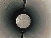
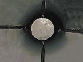
4 ANNUAL COMRESSIVE STRESS CONDITIONS It is known that during the drilling in any well (any perforation hole) in and around the wellbore annular (tangential) compressive stress conditions (stress strain states) are created. The deeper the well, the more compressive stress conditions. Under this action and high overburden pressure occurs a significant reduction of permeability in the near wellbore zone, and in some cases close to near zero. Oil or gas flow can not penetrate to the well. Deterioration of the rock s permeability in the near-wellbore directly from the borehole wall is one of the main causes of the declining production rate of oil and gas wells. This occurs both during drilling and during their operation (figure on the left). Any cumulative or perforation holes only create the additional annular compressive stress conditions around it, and which further deteriorates the collector properties of the productive formation, deteriorate permeability and consequently still reduces the production rate of oil and gas wells. S R - radial stress S e - tangential stress S Z - vertical stress On the rocks lying at depths of 3 5 km the compressive stresses may reach up to MPa. In the near wellbore zone, as a result of concentration these stresses increase and sometimes become equal to or double MPa. If the tectonic stress is several times higher than stress from the weight of rocks, the stress in the near-well zone may be even greater. How is it possible to offload the rocks from its existing shear stresses? How to unload annular compressive stress conditions in the near wellbore zone and thereby improve the permeability and accordingly increase the production rate of oil and gas wells? The idea came from the coal industry (coal mines). Since ancient times, when there were the first coal mines, it was observed, that increasing the depth of the development the coal tunnel, under the action of overburden pressure, surrounding rocks become harder and little-permeable. To solve this problem they developed a cavern of a certain form in the rock. The only possible solution in this situation, in relation to oil and gas wells, is to offload the rocks from its existing shear stress. In particular, the current decrease in near wellbore zone, the hoop stress. In practice, this can be achieved by cutting continuous slots ( windows ) in the vertical section of the wellbore.

 along the wellbore occurs the redistribution of the annular stress conditions to the ends of these slots ( windows ), further from wellbore zone.")
 to 100 cm (3.3 feet).")
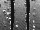
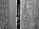
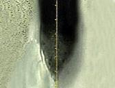
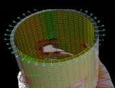
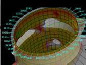
5 CONTINUOUS SLOTS ( WINDOWS ) ALONG THE WELLBORE The first figure below shows that the borehole is surrounded by low permeable "cork" thickness which is approximately 50 % of the well s radius. From figures 2 and 3 shows that two or four diametrically opposite vertical continuous slots is almost twice lower operating on the circuit hole shear stresses, and reduced permeability areas are significantly reduced in size and are pushed into the interior of the reservoir. Thus, the presence of vertical slots significantly improves the situation, and generally retains rock permeability. When cutting of continuous slots ( windows ) along the wellbore occurs the redistribution of the annular stress conditions to the ends of these slots ( windows ), further from wellbore zone. As a result, the stress in the near wellbore zone is reduced. Occurs the unloading of stress state. Accordingly, the permeability in this zone is increase. Accordingly, the productive inflow to the well also is increase. The effect of stress state s discharge occurs at a depth of continuous slots from ~ 30 cm (1 foot) to 100 cm (3.3 feet). How to cut a continuous deep slot along the wellbore section through the casing, cement and further into the productive formation?

6 HOW TO CUT CONTINUOUS SLOTS ( WINDOWS ) ALONG THE WELLBORE How to cut a continuous deep slot along the wellbore section through the casing, cement and further into the productive formation? MINING GEO-MECHANIC S REQUIREMENTS Large opening area of a casing, cement ring and productive formation - it provides a good hydro-dynamic connection between productive layer and the well. The depth of penetration into the productive formation - it provides the unloading the stress conditions in the near wellbore zone and accordingly increases the permeability. Preventing the formation of crusts on the border of opening zone - this prevents the inflow of useful product and requires additional actions. Preventing cracked of cement ring - it provokes the flows of water and increases the risk of well's flooding. All currently known main methods of opening the casing, cement sheath and productive formation (mechanical and jet, shock-explosive and sparing, stressed and unstressed, etc.) have their own drawbacks : detonation impact casing damage cement crack borders clog-up formation damage uncontrolled direction affects the other layers and zones low efficiency unwanted flows generating short duration effect shallow penetration depth increase of annular stress conditions in the near wellbore zone permeability decreasing well life s reducing None of these methods does not create the real continuous, geometrically correct and deep slots ( windows ) along the wellbore, and correspondingly does not discharged stress-strain states in the near wellbore zone. Opening area of casing in all cases is small enough. In additional the efficacy and duration of effect of all currently known additional stimulation s methods (as acoustic, cavitation, chemical treatment, electric, frequency, impact, impulse, laser, magnetic, oscillations, plasma, pneumatic, temperature, ultrasound, vacuum, vibrations, voltage, warming-up, wave, etc.) is directly depends on the size (area) of opening the casing, cement and productive formation. DIMENSION S COMPARISON OF DIFFERENT OPENING S METHODS gun perforation jet perforation shooting perforation abrasive perforation mechanical hydro-slotting perforation


 perforation relates to the main methods of opening the")


.")


7 ABRASIVE JET (HYDRO-JETTING) PERFORATION Slots along the wellbore is possible to cut using abrasive jet perforation or mechanically. But in mechanical methods (circular saw, for example) it is impossible to use abrasive filler, we will not get the deep slots. Consider in more detail an abrasive jet perforation (or point jet perforation). Abrasive jet (hydro-jetting) perforation relates to the main methods of opening the casing, cement sheath and productive formation. AJP is widely used in oil and gas industry as a main opening method, and an auxiliary, for subsequent hydraulic fracture. Abrasive jet perforation does not damage the casing, not crack the cement sheath, and not damage the formation. This is environmentally friendly method (produced water and an abrasive filler). Point jet perforation does not unload the annular compressive stress conditions in the near wellbore zone (profile is the hole D=2.5 cm (1 inch) and L=30 cm (1 foot), and it regardless of the number of holes. The depth of holes does not depend on time application and not becomes deeper. This happens because the reverse jets from the holes hinder direct jets from the nozzles, and perforated rock can not freely go out from the holes (excavation effect does not occur). Increasing the number of nozzles does not create continuous slots too, and only creates additional annular stressful conditions around the perforation holes. To create the continuous and deep slots needed, the interference must be prevented by eliminating the streams from competing. A free exit of perforated rock from the holes must be created, and this is accomplished through MOVING the jets (nozzles) continuously along the wellbore. But such a move is impossible to get by moving the tubing or coiled tubing from the surface. Both tubing and coil tubing have their own frequency and stretch. The working jets will jump (figures on the right) causing a scissor cut. In the best case, a cavern will be formed. The movement of cutting jets (nozzles) shall be applied directly at the cutting place (cutting interval) within the borehole and not depend on the movement of the tubing or coiled tubing.

 all the time are moving to lower from the formed holes, reverse jets from the holes do not interfere direct jets from the nozzles, and perforated rock freely go out from the")
8 CONTINUOUS MOVING JET (HYDRO-JETTING) PERFORATGION The movement of cutting jets (nozzles) shall be applied directly at the cutting place (cutting interval) within the borehole and not depend on the movement of the tubing or coiled tubing. The movement of cutting jets (nozzles) shall be constant and rectilinear, with a speed, enough for cutting casing, cement and deeper into the productive formation. Working jets (nozzles) all the time are moving to lower from the formed holes, reverse jets from the holes do not interfere direct jets from the nozzles, and perforated rock freely go out from the holes to the surface, together with the flow of fluid. The slots in the formation becomes deeper and deeper. Any angles of the nozzles are not necessary. In this case along the wellbore it will be formed continuous and depth slots, with a good enough geometry. Accordingly, will occur unloading of annular stress conditions in the near wellbore zone, and consequently permeability in this area will be increased, which will lead to an increase in the productive flow to the wellbore. Such a movement can be created by a special device with electrical, mechanical or hydraulic / pneumatic principle. HYDRAULIC SLOT-PERFORATION TOOL Hydraulic slot-perforation tool is not only iron. This is research, design, tests and mistakes, manufacture and tests again, continuous improvements and creating of new models. This is geological analysis and determination of the most promising cutting intervals, calculation of the technological parameters for slotting perforation process and cut program instructions. This is special computer programs, skills and knowledge, operational experience and know-how. Finally, it is the intellectual property.
 pressure, the working rod with perforator starts to make rectilinear motion with constant slow velocity.")
 they do not interfere with each other, cut (slot) becomes deeper and deeper, spent")
 position, and the tool can be moved to the next cutting interval.")

9 HYDRAULIC SLOT-PERFORATION TOOL - IT IS VERY EASY The principle of operation are the following. When applying working fluid (produced water and an abrasive filler) pressure, the working rod with perforator starts to make rectilinear motion with constant slow velocity. Jets (2, 3, or 4) of working fluid with abrasive filler start cutting the casing (if the well is cased), cement and further into the productive formation. Since the perforator with working nozzles are constantly moving, forward and reverse jets (from the formed slots) they do not interfere with each other, cut (slot) becomes deeper and deeper, spent abrasive filler and rock freely escapes with the stream of working fluid to the surface. At the stop pressure supply operating rod with perforator is set up to the starting (initial) position, and the tool can be moved to the next cutting interval. Thus it is possible to cut the long continuous slots, or via specified interstices. PATENT US Patent US from October 21, 2014 is the latest invention of hydraulic slot-perforation tool Universal underground hydro-slotting perforation system, controlled by working fluid pressure, for activation and intensification of gas, oil and hydro-geological wells. This patent includes design and operation of ❶ hydraulic unit (slotting perforation engine), ❷ return unit (spring block), ❸ perforator, ❹ nozzles, nozzle-holders and ❺ adapter. ❺ ❶ ❶ ❷ ❸ ❹ ❶ Hydraulic unit (slotting perforation engine), it is a main part of the tool for performing of slotting perforation process. This unit provides the constant rectilinear motion of the working rod with the perforator and working nozzles at a certain speed (speed determines the depth of cut), depending on the operating pressure and temperature of the working fluid. The unit is sealed and autonomous. The valve and the floating pistons provides a change of internal volume, depending on the hydrostatic pressure. The flow controller sets a constant speed of the working rod, depending on temperature and pressure of the working fluid (produced water and an abrasive filler).
 position after stop supply the pressure at the end of the next cutting interval.")
 and spiral action (spiral slots for use in the case with two nozzles in the perforator, and when the direction of the highest fracturing of the")
. Compensators can work with regular tubing only.")


10 ❷ ❻ ❸ ❹ ❺ ❷ Return unit (spring block), it is a part of the slotting perforation tool. This unit provides return of the operating rod of hydraulic slotting perforation engine into the initial (start-up) position after stop supply the pressure at the end of the next cutting interval. The block becomes sealed when the pressure supply. Exists spring blocks of direct action (direct slots) and spiral action (spiral slots for use in the case with two nozzles in the perforator, and when the direction of the highest fracturing of the deposit-field is unknown). It consists of housing, rod, springs, regulating devices, airtight lids and seals. ❻ Compensators using for stimulation of the slotting perforation process in vertical oil, gas, injection or hydro-geological wells (open/cased). Compensators can work with regular tubing only. ❸ Perforators it is an integral part of any slotting perforation process (hydro-slotting, jet slotting, or jet point perforation). Perforator it is the unit of turbulent' s zone, where the working fluid it changes the directory of movement from the working rod direction into the cutting's nozzles. Requirements for perforators: long period of operation (made from one piece of solid metal), ergonomics (low pressure loss), streamlined shape (not scratch the casing), the ability to direct and back flushing even when lowering the tool on the ground. There are many types of perforators varying according to design, type, form, destination, number of nozzles and stiffened ribs, for different type of wells, diameter, tasks, etc. Exist ergonomic, streamlined, multiple use, for vertical and horizontal wells, self-oriented, swiveling, etc. ❹ Nozzles for perforators are made from high quality tungsten mixture of carbide, tungsten, corundum, technical diamond grit and special additives in a definite proportion. Nozzles must to meet all the technological process requirements of the slot perforation process: lasting of work, resistance to high temperature, high pressure, impacts, crumbling and have a hardness of more quartz. Nozzles have a different design and size depending on the shape of the nozzle-holders and perforators, where they are used. ❺ Adapters it is a connecting elements between tubing or coiled tubing and slotting perforation tool. Adapters also can perform other important functions, for example, saddle for a valve ball for testing of tubing or coiled tubing may be located in the shank of slotting perforation tool, or within adapter. Adapters are made from special nonmagnetic material, that is visible in the emissions of radioactive logging during the correlation and installation of the first cutting interval. In this case, adapter also serves as a marker. Exists elongated adapters, smoothing fluctuations of the supply pressure of the working fluid. In this case the adapter partially function as compensator. SECURITY AND SAFETY OF THE TOOL This equipment is environmentally safe (using produced water and an abrasive filler) This equipment is not used any hazards materials (chemical, thermal, radiological, etc.) Hydraulic unit is a closed sealed self-regulating system for prevent explosion under the action of hydrostatic pressure in a water-filled borehole. Perforator is designed so stiffness ribs did not scratch the casing. Perforator does not burrow into the sand completely. If accidentally lowering the tool on the ground remained the possibility of reverse (and direct) flushing. Almost all threaded connections involve the use of Teflon (oil) tape. Rod with the perforator starts to move at a pressure 800 psi (5.5 Mpa). Maximum pressure of the hydraulic fluid 6500 psi (45 Mpa) (taking into account losses in the pipes). With further increase in pressure dosing device in the main piston (hydraulic block) snap on, hydraulic oil will flow through the gap between the main piston and the rod, the rod stops moving. When the pressure drops below 800 psi (5.5 Mpa) or pressure is cut (at the end of cutting, e.g.) rod with a working perforator will be immediately recharged (set-up) to the starting (initial) position, and will be ready for use again (on the next cutting interval, for example) Spring in the return block no operative in a free state. Spring is limited by special washers and nuts on the rod. In addition returning unit is limited by the protective cover from the perforator side. If the spring breaks during the slotting perforation process, the rod with perforator still recharged (set-up) to the starting (initial) position. If perforator will break (even with a base spring rod) then the spring will not pops out from the return block because it will be hold the bottom with the protective cover.
. Instead abrasive quartz sand is needed.")
 with monitoring high pressure line with Manifold block abrasive filler (abrasive quartz sand) lowering the tool correlation log position correction tubing pressure test reverse flushing")

11 HYDRO-SLOTTING PERFORATION PROCESS Surface equipment for slotting perforation process is absolutely standard as for the jet perforation or hydraulic fracturing, only proppant (sticky sand) is not needed (wide vertical slots does not collapse). Instead abrasive quartz sand is needed. rig with crew (or coiled tubing service) tubing (or coiled tubing) wellhead and surface piping tank with formation water cutting tank and abrasive filler mixer (shaker, blender) frac service (pump service) with monitoring high pressure line with Manifold block abrasive filler (abrasive quartz sand) lowering the tool correlation log position correction tubing pressure test reverse flushing cutting first interval direct flushing lifting tool for the next cutting interval cutting next interval direct flushing reverse flushing lifting tool swabbing water The tool is connected to the tubing or coiled tubing through the adapter with standard connections and lowered into the well on a predetermined depth of the first cutting interval. Hydraulic camera will set the volume itself, depending on the hydrostatic pressure. Tubing connections can be checked by the pressure with the valve ball in the adapter. After flushing out a test ball from the adapter to the surface, can be make flushing directly through the tool. After lowering through the tubing the service valve ball in the perforator, tool ready for cutting. When working pressure fluid (produced water and an abrasive filler) is supplied, rod with perforator and nozzles starts to make slow down the linear motion with constant velocity, enough for cutting casing, cement and further into the productive formation. The speed and depth of the cutting slots is regulated by pressure, concentration of abrasive filler and temperature of the working fluid. When stop applying pressure the rod with perforator and nozzles returns to the initial (set-up) position. The tool moves to the next cutting interval and the operation is repeated. After flushing out the service valve ball from the perforator to the surface, can be make flushing directly through the tool.
. Maximum cutting depth with slotting perforation does not exceed 1.5 meters (or 5 feet).")
, but increasing the depth of the jets does not occur.")
.")
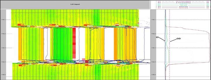
12 HYDRO-SLOTTING PERFORATION PROCESS Some technical parameters of the slotting perforation process. The figure on the left shows a diagram of pressure, slurry rate and abrasive concentration. The figure on the right shows the cutting speed dependence on temperature and pressure (installed in the lab). Maximum cutting depth with slotting perforation does not exceed 1.5 meters (or 5 feet). Greater depth of cut can not be done in connection with the physical and structural features of nozzles. With increasing pressure, increases only conicity of jets behind the nozzles (increases spraying zone), but increasing the depth of the jets does not occur. For a real increase in the cutting jets it is necessary to extend the body of nozzles, that is impossible to make - the length of the nozzles must be greater than the diameter of the well. Diameter of the tubing or coiled tubing is not very important, slot-perforation tool is connected to the tubing or coiled tubing through the standard adapters (varying diameters). The size of the tubing can be limited only by design of the internal diameter of the working rod in the slot-perforation tool and is equal to 30 mm (1.2 inches). But in such a small diameter, pressure losses in the pipes will be quite large. Therefore, with respect to the diameter of tubing or coiled tubing is possible to say: the more - the better. Pressure increase leads to the simulation of hydraulic fracturing, and an increase in the concentration of an abrasive additive causes early erosion nozzles and perforator, but does not affect the depth. Much more important design parameter is the internal diameter of casing in vertical wells (or open hole for horizontal wells). Currently the design of slotting perforation equipment allows to operate in the wells with casing OD=100 mm (4 inches) for vertical wells, and OD= 120 mm (4.5 inches) for horizontal wells. In the nearest future it is planned to create slotting perforation equipment for operate in the wells with OD=75 mm (3 inches) and OD=89 mm (3.5 inches). Tool orientation in horizontal wells. Currently there is only a self-oriented (self- aligning) perforator for horizontal wells (figure on the right). Perforator can can create vertical slot in the upper direction or vertical slot in the down direction in the horizontal wellbore.


13 GEOMETRY OF CUTTING SLOTS ( WINDOWS ) Cutting depth is adjustable parameter. Cutting length depends on the length of the working rod. The number of slots depends on the number of nozzles in the perforator. WHAT CAN BE DONE WITH SLOTTING PERFORATION TOOL thin interbedded layers shale s near the water few casings mini fracturing bypass couplings chemical treatment direct/reverse flush


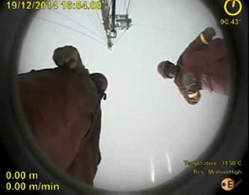
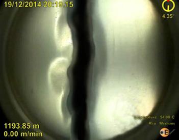
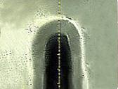
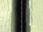


14 RESULTS AFTER THE WORK OF A HYDRAULIC SLOT-PERFORATION TOOL
 opening area per one linear meter up to 6 m² (2 nozzles), and 12 m² (4 nozzles) opening area per one linear foot up to 20 ft² (2 nozzles), and 40 ft² (4 nozzles) cutting speed is one")


15 BENEFITS FROM HYDRO-SLOTTING PERFORATION ecologically safe, environmentally friendly (produced water and an abrasive filler) penetration depth is up to 1.5 m (5 feet) opening area per one linear meter up to 6 m² (2 nozzles), and 12 m² (4 nozzles) opening area per one linear foot up to 20 ft² (2 nozzles), and 40 ft² (4 nozzles) cutting speed is one linear foot per 60 min (cased wells) and one linear foot per 30 min (open hole) simultaneous cutting 2, 3, and 4 slots along the wellbore no detonation impact, no casing damage, no cement cracks, no clog-up the formation borders unloading of the annular compressive stress conditions in the near wellbore zone up to % accordingly increase of permeability up to % accordingly increase the useful inflow up to 5-10 times can be used in oil, gas, and injection wells can be used in newly drilled and low productivity, low debit wells can be used in vertical and horizontal wells, with tubing and coiled tubing can be used in any formation (sandstone, carbonates, shale s, thinly interbedded, quicksand, etc.) can be used near the water reservoirs (impossible to make a hydraulic fracturing) extract more than 20 % of additional oil from the layers with higher productivity duration of the effect over 10 years make an excellent geometry for subsequent fracturing (if necessary)


 the efficacy and duration of effect which is directly depends on the size (area) of opening the casing, cement")


16 WHERE IS HYDRO-SLOTTING POSSIBLE TO USE? In sandstones, carbonates, shale s, thinly interbedded formations. In oil and gas, vertical and horizontal, newly drilled, low-debit and low productivity wells. In low-temperature and low-viscosity wells. It is certainly better to use hydro-slotting perforation for its intended purpose, as a way of opening casing, cement and productive formation with the effect of annular stress conditions unloading in newly drilled wells, than later treat problem wells. Near the water reservoirs, for subsequent hydraulic fracture and additional stimulation s methods (acoustic, cavitation, chemical treatment, electric, frequency, impact, impulse, laser, magnetic, oscillations, plasma, pneumatic, temperature, ultrasound, vacuum, vibrations, voltage, warming-up, wave, etc.) the efficacy and duration of effect which is directly depends on the size (area) of opening the casing, cement and productive formation. SOME EXAMPLE - THINLY INTERBEDDED FORMATION The picture below shows example of thinly interbedded formation (top and side view), similar to shale formation. Top view shows only one limited layer. How are you going to open this information? Of course, by traditional methods - cumulative or jet perforation and, if not near aquifers, hydraulic fracturing. Drilled well before the opening After cumulative or jet perforation After subsequent hydraulic fracturing After hydro-slotting perforation Hydro-slotting perforation just cut through all the of thinly interbedded layers entirely and without residue, plus unloaded the annular stress conditions in the near wellbore zone.


 of the stress conditions in the near wellbore zone (up to 50-100 %).")
17 SOME EXAMPLE - CRUMBLING SAND Let's consider an another case. Crumbling (losing) sand - a fairly common well's problem in some regions. Is it possible to treat this problem with hydro-slotting perforation? At first glance, this is not possible. Feed an abrasive under the high pressure into the well, which is already colmatated by crumbling sand! Let's look at it from a different perspective. Firstly, how to remove the sand through small holes in the casing? Yes, with water jets under high pressure, or by different methods of stimulation may clear the holes, but remove sand behind the casing and cement is impossible. It is necessary to cut casing and cement to clean sand from the entire colmatation zone. Second, the sand falls into the channels in the near wellbore under the action of rock pressure. Continuous slots along the wellbore allow unloading of the annular compressive stress-strain states around the wellbore zone. Rock pressure to the sand will be reduced, crumbling of sand will be weakened. Occurs unloading (discharging) of the stress conditions in the near wellbore zone (up to %). As a consequence the rock pressure on the sandy rocks in the near-wellbore area (in radius ~ feet around the well) become smaller, and sand stops to crumble. Breaking component of oil flow rate is reduced. It does not mean that the flow becomes less. Example. Suppose that through a hole in casing after cumulative perforation with the maximum diameter ~ 2 and the area ~ 3.14 square feet passes 1 barrel of oil per hour (in the case of a broken casing after hydraulic fracturing the area of hole ~ square feet). One full slot after slotting perforation has an area of hole ~ square feet. Let the flow of oil through the hole 40 square feet will remain the same: 1 barrel of oil per hour. But the total flow rate through the large hole will be less, respectively destructive component will also be less, respectively, the effect will be much longer. SOME EXAMPLE - HORIZONTAL WELL One more example of opening the productive layer in a horizontal wellbore with hydraulic fracturing and hydro-slotting perforation. Slots after hydro-slotting perforation are within the productive formation horizon (located along the productive horizon). Drilled well before the operation After perforation and subsequent hydraulic fracturing After hydro-slotting perforation
18 HYDRAULIC FRACTURING AND HYDRO-SLOTTING Hydraulic fracturing (fracking) - hydraulically pressurized liquid made of water, sand, and chemicals. Hydraulic Fracturing is the most powerful method, creating very long cracks and micro cracks spread in the direction of the greatest fracture. Fracturing relates to methods of opening the productive formation, but it can be applied only after one of the known methods of opening the casing: Shock-explosive: bullet (gun perforation) and cumulative perforation; Unstressed: methods of point perforation and continuous opening; Positive aspects: Very large area of opening; Large productive inflow (especially in the initial stage); Negative aspects: The process has practically no control; The process affects the other layers and zones; Cracks and micro cracks of large length extend the boundaries of producing formation and transferred to other layers; Coefficient of efficiency sometimes reduced up to 40 % (within productive formation), the remaining 60 % are harmful; Violation of the integrity of a producing formation; Combining unwanted productive and non-productive reservoirs; Generating unwanted flows; Pulling up the water with subsequent flooding of the productive layer; Reducing the life of the well. Coefficient of efficiency of hydraulic fracturing in shale s or thinly interbedded layers, for example, is very low and financially not beneficial. Hydro-slotting perforation - continuous moving jet slotting perforation. Hydro-slotting perforation is the most effective method of opening the casing, cement and productive formation. Uses a special slotting perforation tool that produces linear motion with constant velocity of abrasive cutting jets along the wellbore, and without moving the tubing from the surface. Positive aspects: Ecologically safe, environmentally friendly (water and sand); Very long duration of effect (up to years); Opportunity of using near the water reservoirs (impossible to make a hydraulic fracturing); The process is controlled (length and depth of slots); The process takes place within the productive formation, and not affects other layers and zones; Large opening area, penetration depth is up to 5 feet; No detonation impact, no casing damage, no cement cracks, no clog-up the formation in borders; Unloading the tangential circle stress conditions in the near wellbore zone up to %; Increases the collecting properties in the near wellbore zone; Increase of the drainage volume characteristics in more than 6 times; Increase of permeability and accordingly increase the useful inflow up to %; Opportunity to use in any wells and in any formations; Negative aspects: The process is quite complicated in the performance; Hydro-slotting perforation perfectly working in sandstones and carbonates, thinly interbedded formations, shale s, etc. Coefficient of efficiency of HSP in shale s and thinly interbedded layers is very high.


.")


19 HYDRO-SLOTTING PERFORATION IS NOT A MAGIC WAND FOR ALL OCCASIONS According to classification the hydro-slotting perforation relates to methods of opening the productive formation. Hydro-slotting perforation it is accurate, and quite effective method, but it is not a magic wand for all occasions. Necessary to understand all the advantages of this method based on the physics of the phenomena of unloading the annular compressive stress-strain states around the wellbore zone, depth of created slots, opening area of the formation, operating principle and so on. If in the well oil or gas is over, or productive layers have watered (or cement has cracks for water overflows), then no method will help anymore. Or if the well is working perfectly and gives productive influx of hundreds barrels per day, then no method will increase such influx in twice (except additional new drilling). Cause of the fall of productive influx is a lot: In which wells can slotting perforation be used? Is preferable: Oil or gas is over Fall intrastate pressure Flooding of producing layer Chemical damage of the productive formation Incorrect grid drilling Incorrect development Incorrect exploitation Colmatation Poor hydrodynamic connection of the well with producing layer Low temperature, high viscosity, etc. Oil, gas and injection wells Vertical and horizontal wells Newly drilled and old wells Sandstone, carbonate, shale, etc. formations Shallow and deep wells High-temperature and low-temperature wells Low-viscosity and high-viscosity, etc. Newly drilled wells, or old wells with the following criteria: Old wells with the following criteria: Having no problems with the water during operation; Total period of operation not exceeding years; Designed exclusively via gun perforation or cumulative perforation; Designed exclusively via hydraulic fracturing, but without water during the whole period of operation; The operational reservoirs one or two; Having a very good productive inflow in early or mid-operation; Currently idle or even abandonment; Currently Inflow bod;


20 OIL AND GAS WELL SLOTTING PERFORATION PROFESSIONAL SERVICE CONTINUOUS MOVING JET SLOTTING PERFORATION TECHNOLOGY FOR VERTICAL AND HORIZONTAL WELLS
 359-2559 (647) 291-8707 info@maxxwell.")
21 616 Corporate Way 2, # 4201 Valley Cottage, NY United States N. Rainbow Blvd., # 5353 Las Vegas, NV United States Beechbrooke way Aurora, ON Canada L4G 6N7 Toll free: Tel: (716) (647) info@maxxwell.us info@maxxwell.ca info@maxxwell.net
Perforation Design for Well Stimulation. R. D. Barree Barree & Associates LLC
 Perforation Design for Well Stimulation R. D. Barree Barree & Associates LLC Typical Shaped Charge Primer charge Main explosive charge Case or container Detonating cord groove ¾ point of initiation Liner
TECHNICAL BENEFITS OF CJS / RAISE HSP. Technical Advantages
 TECHNICAL BENEFITS OF CJS / RAISE HSP Technical Advantages The HSP is designed for low- to mid- volume applications at flow rates of 1 cubic meter to 30 c. m per day. The benefits are in the details. The
Perforating Options Currently Available in Horizontal Shale Oil and Gas Wells. Kerry Daly, Global BD Manager- DST TCP
 MENAPS 2013 Perforating Options Currently Available in Horizontal Shale Oil and Gas Wells Kerry Daly, Global BD Manager- DST TCP MENAPS 13-17 WELL FLOW MANAGEMENT TM Scope/ Contents: MENAPS 13-17 Study
Testing Services Overview
 2 Jet Research Center JRC Jet Research Center Perforating Center of Excellence Testing Services Overview API RP19B Testing Advanced Testing Operational Testing API RP19B Testing The American Petroleum
W I L D W E L L C O N T R O L FLUIDS
 FLUIDS Fluids Learning Objectives You will learn about different fluids that can be used in well control. You will become familiar with the characteristics and limitations of fluids. You will learn general
Construction Dewatering
 Construction Dewatering Introduction The control of groundwater is one of the most common and complicated problems encountered on a construction site. Construction dewatering can become a costly issue
ARTICLE. Overcome casing integrity issues in your plug-and-perf operations
 ARTICLE Overcome casing integrity issues in your plug-and-perf operations CONTENT A challenge to plug-and-perf success 3 Causes of casing restrictions 9 How extended-range frac plugs keep operations moving
Drilling Efficiency Utilizing Coriolis Flow Technology
 Session 12: Drilling Efficiency Utilizing Coriolis Flow Technology Clement Cabanayan Emerson Process Management Abstract Continuous, accurate and reliable measurement of drilling fluid volumes and densities
Perforating Center of Excellence TESTING SERVICES OVERVIEW
 Perforating Center of Excellence TESTING SERVICES OVERVIEW Jet Research Center (JRC) is the leader in energetic research and testing for the oil and gas industry. Since introducing jet perforators for
Advanced Applications of Wireline Cased-Hole Formation Testers. Adriaan Gisolf, Vladislav Achourov, Mario Ardila, Schlumberger
 Advanced Applications of Wireline Cased-Hole Formation Testers Adriaan Gisolf, Vladislav Achourov, Mario Ardila, Schlumberger Agenda Introduction to Cased Hole Formation tester Tool specifications Applications
Coal Bed Methane (CBM) Permeability Testing
 Permeability Testing") Coal Bed Methane (CBM) Permeability Testing WTN Network Meeting April 28-29, 2011 ExxonMobil Exploration / Well Testing Team CBM Flow Characteristics Flow mechanism Gas desorbs when pressure drops below
Coal Bed Methane (CBM) Permeability Testing WTN Network Meeting April 28-29, 2011 ExxonMobil Exploration / Well Testing Team CBM Flow Characteristics Flow mechanism Gas desorbs when pressure drops below
Inflatable Packer Single & Double. Single & Double Packer Dimension. Wireline Packer. Water Testing Packer (WTP) Packer
 Packer") Inflatable Packer Single & Double Single & Double Packer Dimension Wireline Packer Water Testing Packer (WTP) Packer Packer Working Pressure & Depth Chart Packer Water Hand Pump Packer Air Driven Pump
Inflatable Packer Single & Double Single & Double Packer Dimension Wireline Packer Water Testing Packer (WTP) Packer Packer Working Pressure & Depth Chart Packer Water Hand Pump Packer Air Driven Pump
APPENDIX A1 - Drilling and completion work programme
 APPENDIX A1 - Drilling and completion work programme Information about the well and drilling To the extent possible, the international system of units (SI) should be adhered to, and the drilling programme
Exercise 2-3. Flow Rate and Velocity EXERCISE OBJECTIVE C C C
 Exercise 2-3 EXERCISE OBJECTIVE C C C To describe the operation of a flow control valve; To establish the relationship between flow rate and velocity; To operate meter-in, meter-out, and bypass flow control
then the work done is, if the force and the displacement are in opposite directions, then the work done is.
 1. What is the formula for work? W= x 2. What are the 8 forms of energy? 3. Write the formula for the following: Kinetic Energy Potential Energy 4. If the force and the displacement are in the same direction,
OCEAN DRILLING PROGRAM
 BIH OCEAN DRILLING PROGRAM www.oceandrilling.org Scientifi c Application Packers A packer is an inflatable rubber element that inflates to seal the annular space between the drill string and the borehole
W I L D W E L L C O N T R O L PRESSURE BASICS AND CONCEPTS
 PRESSURE BASICS AND CONCEPTS Pressure Basics and Concepts Learning Objectives You will be familiarized with the following basic pressure concepts: Defining pressure Hydrostatic pressure Pressure gradient
Worked Questions and Answers
 Worked Questions and Answers A Learning Document for prospective Candidates For the Rotary Drilling Well Control Test Programme Copyright, IWCF June 2000 Revision No.1, November 2000 IWCF 2000 page 1 of
Squeeze Cementing. Brett W. Williams Cementing Technical Advisor January 2016 Tulsa API Meeting
 Squeeze Cementing Brett W. Williams Cementing Technical Advisor January 2016 Tulsa API Meeting Definition Squeeze Cementing is the process of applying hydraulic pressure to force or squeeze a cement slurry
Permeability. Darcy's Law
 Permeability Permeability is a property of the porous medium that measures the capacity and ability of the formation to transmit fluids. The rock permeability, k, is a very important rock property because
Extreme Overbalance, Propellant OR Extreme Underbalance. When and how EOP, Propellant or EUP could effectively improve the well s perforation
 Extreme Overbalance, Propellant OR Extreme Underbalance When and how EOP, Propellant or EUP could effectively improve the well s perforation The first 130 years of perforating 1865, Tin torpedos filled
DAY ONE. 2. Referring to the last question, what mud weight would be required to BALANCE normal formation pressure?
 DAY ONE 1. Normal formation pressure gradient is generally assumed to be: A..496 psi/ft B..564 psi/ft C..376 psi/ft D..465 psi/ft 2. Referring to the last question, what mud weight would be required to
Hydro-Mech Bridge Plug
 Manual No: 0620000303 Revision: F Approved By: Quality Engineer Date: 2014-9-9 Hydro-Mech Bridge Plug DESCRIPTION: Map Hydro-Mech Bridge Plug is hydraulically actuated and mechanically set. Compact, with
CHDT Cased Hole Dynamics Tester. Pressure testing and sampling in cased wells
 CHDT Cased Hole Dynamics Tester testing and sampling in cased wells Applications Evaluation of old wells for bypassed hydrocarbons Development of critical economic data for well evaluation Reduced-risk
Paper #: POWER
 Proceedings of POWER2008 ASME Power 2008 July 22-24, 2008, Orlando, Florida, USA Paper #: POWER2008-60061 THE USE OF AN EDDY CURRENT INSPECTION OF BRASS TUBES IN A SURFACE CONDENSER TO PROVIDE A CONDITION
Captains Meeting 2009 Introduction to Well Testing- Expro. Edwin Schoorl
 Captains Meeting 2009 Introduction to Well Testing- Expro Edwin Schoorl Agenda Oil and Gas presence Well construction Well testing Welltest System Welltest Equipment Welltest Video Questions Oil and gas
Seismic Sources. Seismic sources. Recorders. Requirements; Principles; Onshore, offshore. Digitals recorders; Analog-to-Digital (A/D) converters.
 converters.") Seismic Sources Seismic sources Requirements; Principles; Onshore, offshore. Recorders Digitals recorders; Analog-to-Digital (A/D) converters. Reading: Reynolds, Section 4.5 Telford et al., Section 4.5
Seismic Sources Seismic sources Requirements; Principles; Onshore, offshore. Recorders Digitals recorders; Analog-to-Digital (A/D) converters. Reading: Reynolds, Section 4.5 Telford et al., Section 4.5
DIRECTIONAL DRILLING
 DIRECTIONAL DRILLING 1. General. Installation of pipelines through the levee embankment using directional drilling technology is prohibited. Installation of pipelines through a flood control project foundation
FREQUENTLY ASKED QUESTIONS
 What are some applications in which you ve successfully used this product? New Completions - Stage by Stage Diversion Between Frac plugs for Intra-Stage Diversion Replace Frac Plugs with Perf PODs - Full
Vibration isolation system 1VIS10W. User manual
 Vibration isolation system 1VIS10W User manual Standa 2014 Table of contents 1. General information 3 1.1. Introduction 3 1.1.1. Safety 5 1.2. Location of the table 5 1.3. Air supply requirements 5 2.
. In an elevator accelerating upward (A) both the elevator accelerating upward (B) the first is equations are valid
 both the elevator accelerating upward (B) the first is equations are valid") IIT JEE Achiever 2014 Ist Year Physics-2: Worksheet-1 Date: 2014-06-26 Hydrostatics 1. A liquid can easily change its shape but a solid cannot because (A) the density of a liquid is smaller than that of
IIT JEE Achiever 2014 Ist Year Physics-2: Worksheet-1 Date: 2014-06-26 Hydrostatics 1. A liquid can easily change its shape but a solid cannot because (A) the density of a liquid is smaller than that of
DB Bridge Plug. Features. Benefits. Applications
 DB Bridge Plug The WELLFIRST Premium Cast Iron Bridge Plug designed to run on electric line. Rated between 2000-10000-psi differential, and 300 F from above and below. Features Field Proven Design Constructed
THE INNER WORKINGS OF A SIPHON Jacques Chaurette p. eng. January 2003
 THE INNER WORKINGS OF A SIPHON Jacques Chaurette p. eng. www.lightmypump.com January 2003 Synopsis The objective of this article is to explain how a siphon works. The difference between low pressure, atmospheric
Casing Design. Casing Design. By Dr. Khaled El-shreef
 Casing Design By Dr. Khaled El-shreef 1 Casing Design CONTENTS Function of Casing Casing Types & Tools Strength Properties Casing Specification Casing Design 2 1 RUNNING AND CEMENTING CASING Reasons for
COAL SEAM METHANE - EXPLORATION AND PRODUCTION
 COAL SEAM METHANE - EXPLORATION AND PRODUCTION Dr Ian Gray, Principal Sigra Pty Ltd, 72 Donaldson Road, Rocklea, Queensland 4106 Australia. Tel +61 7 3216 6344, Fax +61 7 3216 6988, WWW: www.sigra.com.au
Autodesk Moldflow Communicator Process settings
 Autodesk Moldflow Communicator 212 Process settings Revision 1, 3 March 211. Contents Chapter 1 Process settings....................................... 1 Profiles.................................................
(Refer Slide Time: 2:16)
") Fluid Machines. Professor Sankar Kumar Som. Department Of Mechanical Engineering. Indian Institute Of Technology Kharagpur. Lecture-23. Diffuser and Cavitation. Good morning and welcome you all to this
Fluid Machines. Professor Sankar Kumar Som. Department Of Mechanical Engineering. Indian Institute Of Technology Kharagpur. Lecture-23. Diffuser and Cavitation. Good morning and welcome you all to this
The key to connectivity
 The key to connectivity Kerry Daly, Global BD Manager, Tubing Conveyed Perforating (TCP) First published by Oilfield Technology, November 2015 Connecting oil or gas-bearing formations with the wellbore
RULES OF THE OIL AND GAS PROGRAM DIVISION OF WATER RESOURCES CHAPTER DRILLING WELLS TABLE OF CONTENTS
 RULES OF THE OIL AND GAS PROGRAM DIVISION OF WATER RESOURCES CHAPTER 0400-52-06 DRILLING WELLS TABLE OF CONTENTS 0400-52-06-.01 Drilling Equipment 0400-52-06-.03 Casingheads 0400-52-06-.02 Blowout Prevention
Industry Code: Alberta Small Employer OHS Legislated Requirements
 This document is a guideline only. Employers have a responsibility of assessing all applicable occupational health and safety legislation, for the tasks they are performing. Services in this industry can
GEOTHERMAL WELL COMPLETION TESTS
 GEOTHERMAL WELL COMPLETION TESTS Hagen Hole Geothermal Consultants NZ Ltd., Birkenhead, Auckland, New Zealand. ABSTRACT This paper reviews the measurements that are typically made in a well immediately
Irrigation &Hydraulics Department lb / ft to kg/lit.
 CAIRO UNIVERSITY FLUID MECHANICS Faculty of Engineering nd Year CIVIL ENG. Irrigation &Hydraulics Department 010-011 1. FLUID PROPERTIES 1. Identify the dimensions and units for the following engineering
Perforation Techniques in brown fields for Production optimization.
 P-085 Perforation Techniques in brown fields for Production optimization. Summary *Prof. Asit Kumar Samadder,UPES Different techniques are adopted for perforation like conventional perforation with casing
BUTTERFLY VALVES. Toll Free (877) - ICFLUID -2-
 - ICFLUID -2-") BUTTERFLY VALVES 1. General HyrdoWer is a globally recognized manufacturer of power unit accessories. They have become specialists in the design of Butterfly Valves and Hydraulic Compensators. The shut
BUTTERFLY VALVES 1. General HyrdoWer is a globally recognized manufacturer of power unit accessories. They have become specialists in the design of Butterfly Valves and Hydraulic Compensators. The shut
IWCF Equipment Sample Questions (Combination of Surface and Subsea Stack)
") IWCF Equipment Sample Questions (Combination of Surface and Subsea Stack) 1. Given the volumes below, how much hydraulic fluid will be required to carry out the following operations (no safety margin)?
IWCF Equipment Sample Questions (Combination of Surface and Subsea Stack) 1. Given the volumes below, how much hydraulic fluid will be required to carry out the following operations (no safety margin)?
PHYS 101 Previous Exam Problems
 PHYS 101 Previous Exam Problems CHAPTER 14 Fluids Fluids at rest pressure vs. depth Pascal s principle Archimedes s principle Buoynat forces Fluids in motion: Continuity & Bernoulli equations 1. How deep
GROUTEC SCOTT VICKERS. Grouting Equipment
 GROUTEC SCOTT VICKERS Grouting Equipment SCOTT VICKERS manufacturers a range of cement and chemical grouting equipment including:- PUMPS - The Cement Grout Pumps are all diaphragm-type. These diaphragms,
Design, Static Structural & Model Analysis of Water Ring Vacuum Pump Impeller
 IJSRD - International Journal for Scientific Research & Development Vol. 6, Issue 03, 2018 ISSN (online): 2321-0613 Design, Static Structural & Model Analysis of Water Ring Vacuum Pump Impeller Ajay A.
Computer Simulation Helps Improve Vertical Column Induced Gas Flotation (IGF) System
 System") JOURNAL ARTICLES BY FLUENT SOFTWARE USERS JA187 Computer Simulation Helps Improve Vertical Column Induced Gas Flotation (IGF) System Computer simulation has helped NATCO engineers make dramatic improvements
JOURNAL ARTICLES BY FLUENT SOFTWARE USERS JA187 Computer Simulation Helps Improve Vertical Column Induced Gas Flotation (IGF) System Computer simulation has helped NATCO engineers make dramatic improvements
DR.ING. CARLO AVANZINI PROFESSIONAL ENGINEER GRIP TEST REPORT NOVA SIRIA, ROLETTO, Premise
 GRIP TEST REPORT NOVA SIRIA, ROLETTO, 07.10.2013 1. Premise The present report covers the witnessing of the test conducted in the Nova Siria Factory in Roletto (Torino, Italy) to verify the behavior of
THE INFLOW OF UNWANTED AIR
 IN PRESSURIZED PIPES The main reason for the inflow of air in public water distribution systems is excessive water velocity. Air traveling with water in pressurized pipes can result in high turbulence
Float Equipment TYPE 925/926
 Type 925 Float Collar Plunger Valve Float Equipment For less demanding well conditions, such as shallower depths or lower pressures, Top- Co offers economical float equipment certified to API RP 10F category
Item 404 Driving Piling
 Item Driving Piling 1. DESCRIPTION Drive piling. 2. EQUIPMENT 2.1. Driving Equipment. Use power hammers for driving piling with specified bearing resistance. Use power hammers that comply with Table 1.
3 1 PRESSURE. This is illustrated in Fig. 3 3.
 P = 3 psi 66 FLUID MECHANICS 150 pounds A feet = 50 in P = 6 psi P = s W 150 lbf n = = 50 in = 3 psi A feet FIGURE 3 1 The normal stress (or pressure ) on the feet of a chubby person is much greater than
OPERATION. Estimated kerf width compensation. HPR260 Manual Gas Instruction Manual 4-9
 Estimated kerf width compensation The widths in the chart below are for reference. Differences between installations and material composition may cause the specific user results to vary from those shown
SPECIFYING MOTIONLESS MIXERS
 SPECIFYING MOTIONLESS MIXERS The operating cost for the energy necessary to mix fluids with a motionless mixer is usually far lower than for any competitive mixing technique. An extruder which melts, mixes
Drilling and Blasting Technology Prof. Kaushik Dey Department of Mining Engineering Indian Institute of Technology, Kharagpur
 Drilling and Blasting Technology Prof. Kaushik Dey Department of Mining Engineering Indian Institute of Technology, Kharagpur Lecture 28 Surface blasting-1 Let me welcome you to the lecture number 28 of
Dean Pump Self-Priming Chemical Process Pumps
 Bulletin C 1.2.34.7 Dean Pump Self-Priming Chemical Process Pumps php Series HEAD CAPACITY RANGE CHARTS php Self Primer - 2 Pole 3500 RPM 500 CAPACITY M 3 /HR 2900 RPM 50 HERTZ 25 50 75 125 150 400 TOTAL
WILD WELL CONTROL WARNING SIGNS OF KICKS
 WARNING SIGNS OF KICKS Warning Signs of Kicks Learning Objectives You will learn the warning signs that indicate the well may be kicking: Warning signs of kicks False kick indicators You will also learn
DBML-60/80 Squeeze Tool
 DBML-60/80 Squeeze Tool OPERATORS MANUAL Description The Mustang Model DBML-60/80 Hydraulic squeeze tool has been manufactured since 1995. A Mustang 3 3/4 bore doubleacting cylinder producing 41,000 lbs
Limited Entry Revolution
 Limited Entry Revolution Improving cemented liner completions with advanced ball-drop technology Oil and gas producers have succeeded in boosting production from horizontal wells in unconventional reservoirs
PRO SINK -R 1 and 2. Dilution system CONTENTS
 PRO SINK -R 1 and 2 Dilution system CONTENTS 1.0 Product description 2 2.0 Warnings.. 3 3.0 Installation procedure 4 4.0 Plumbing connections 4 5.0 Technical features.. 5 6.0 Maintenance... 6 7.0 Troubleshooting......6
User's Manual. MixRite TF 10. Edition 05.08
 User's Manual MixRite TF 10 Edition 05.08 1 Tefen MixRite TF 10 fertilizer and chemicals Injector Congratulations on your purchase of one of Tefen s high quality products. To get the best results from
E 328 E 498 Tank top mounting Connection up to G1½ / -24 SAE and SAE 2 Nominal flow rate up to 600 l/min / gpm
 Return-Suction Filters E 8 E 98 Tank top mounting Connection up to G½ / - SE and SE Nominal flow rate up to 6 l/min / 8. gpm Description pplication For operation in units with hydrostatic drives, when
Introduction. Part one: Identify the Hydraulic Trainer Components
 The University Of Jordan School of Engineering Mechatronics Engineering Department Fluid Power Engineering Lab Experiments No.4 Introduction to Hydraulic Trainer Objective: Students will be able to identify
22. Specialty Valves.
 22. Specialty Valves. a. Types of Specialty Valves. 1) Use of the following specialty valves is covered in this section: Altitude Valve, Pressure Reducing Valve, Pressure Relief Valve, Swing Check Valve,
TUTORIAL. NPSHA for those who hate that stuffy word. by Jacques Chaurette p. eng. copyright 2006
 TUTORIAL NPSHA for those who hate that stuffy word by Jacques Chaurette p. eng. www.lightmypump.com copyright 2006 page.2 NPSHA for those who hate that stuffy word This article follows the same approach
Understanding pressure and pressure
 CHAPTER 1 1-1 PRESSURE BASICS Remember to think downhole. The concepts provided in this section cover the foundations for good well control. Understanding pressure and pressure relationships is important
CHAPTER 5: VACUUM TEST WITH VERTICAL DRAINS
 CHAPTER 5: VACUUM TEST WITH VERTICAL DRAINS 5.1 Introduction Using surcharging as the sole soil consolidation mean can take a long time to reach the desired soil settlement. Soil consolidation using prefabricated
Analysis of 24-Hour Pump Test in Well NC-EWDP-3S, Near Yucca Mountain, Nevada
 Analysis of 24-Hour Pump Test in Well NC-EWDP-3S, Near Yucca Mountain, Nevada Prepared for: Nye County Department of Natural Resources and Federal Facilities, Nuclear Waste Repository Project Office, Grant
OIL AND GAS DOCKET NO
 OIL AND GAS DOCKET NO. 09-0241077 THE APPLICATION OF GILBOW TANK TRUCK SERVICE, INC., TO DISPOSE OF OIL AND GAS WASTE BY INJECTION INTO A POROUS FORMATION NOT PRODUCTIVE OF OIL OR GAS, GILBOW WELL NO.
Gas Lift Workshop Doha Qatar 4-88 February Gas Lift Optimisation of Long Horizontal Wells. by Juan Carlos Mantecon
 Gas Lift Workshop Doha Qatar 4-88 February 2007 Gas Lift Optimisation of Long Horizontal Wells by Juan Carlos Mantecon 1 Long Horizontal Wells The flow behavior of long horizontal wells is similar to pipelines
ATD LB PRESSURE BLASTER INSTRUCTION MANUAL
 ATD-8402 90LB PRESSURE BLASTER INSTRUCTION MANUAL SAVE THESE INSTRUCTIONS SAFETY INSTRUCTIONS FOR SANDBLASTER 1. Before opening the tank release the air pressure on the sand tank. To do this, turn off
DEVELOPMENT OF A ROBUST PUSH-IN PRESSUREMETER
 DEVELOPMENT OF A ROBUST PUSH-IN PRESSUREMETER Roger Failmezger, P.E. In-Situ Soil Testing, L.C., Lancaster, Virginia, USA ABSTRACT A push-in pressuremeter was developed using slotted steel casing with
Extended leak off testing
 Extended leak off testing Rev: 1.0 03/01/01 Purpose To ensure minimal operational time and risk exposure to personnel, process, production and equipment. The following extended leak off test procedures
A COMPARATIVE STUDY OF PARAFFIN WAX
 In: Advances in Sustainable Petroleum Engineering and Science ISSN: 1937-7991 Volume 2, Number 2 211 Nova Science Publishers, Inc. A COMPARATIVE STUDY OF PARAFFIN WAX AND BEESWAX WITH A VIEW TO SIMULATING
Innovating Gas-Lift for Life of Well Artificial Lift Solution. The Unconventional Solution!
 Innovating Gas-Lift for Life of Well Artificial Lift Solution The Unconventional Solution! Glenn Wilde Optimum Production Technologies Inc. Revive Energy Corp. Unconventional Oil & Gas Resources Unconventional
Pump Selection and Sizing (ENGINEERING DESIGN GUIDELINE)
") Guidelines for Processing Plant Page : 1 of 64 Feb 2007 (ENGINEERING DESIGN GUIDELINE) Author: A L Ling Checked by: Karl Kolmetz TABLE OF CONTENT INTRODUCTION Scope 5 General Design Consideration Type
Guidelines for Processing Plant Page : 1 of 64 Feb 2007 (ENGINEERING DESIGN GUIDELINE) Author: A L Ling Checked by: Karl Kolmetz TABLE OF CONTENT INTRODUCTION Scope 5 General Design Consideration Type
Blowout during Workover Operation A case study Narration by: Tarsem Singh & Arvind Jain, OISD
 1. Introduction An incident of gas leakage from a well took place during workover operations. Subsequently, the gas caught fire on the fourth day in which twelve persons were injured. Two contract workers,
S.M.A.R.T.S. Stimulation Monitoring and Reservoir Testing Software tm
 S.M.A.R.T.S. Stimulation Monitoring and Reservoir Testing Software tm Guydon Software Services 3813 Coronado Ct, Weatherford, TX 76087-9003 Office (817) 441-2575 Fax (817) 441-2576 1 S.M.A.R.T.S. Stimulation
EXAMINER S REPORT AND RECOMMENDATION STATEMENT OF THE CASE
 OIL AND GAS DO0KET NO. 01-0249550 THE APPLICATION OF REGENCY FS LP UNDER RULE 36 AND RULE 46 TO DISPOSE OF OIL AND WASTE CONTAINING HYDROGEN SULFIDE GAS INTO ITS TILDEN GPI WELL NO. 1, TILDEN, S. (WILCOX
Chapter 5 HORIZONTAL DRILLING
 Chapter 5 HORIZONTAL DRILLING Chapter 5 How much money am I about to put on the table for a horizontal well? Did I do sufficient planning? Keys to Successful Horizontal Wells Multi-disciplined teams working
FRAC FLUIDS AND WATER USAGE Evaluating The Commercial Viability and Success In Using Water-Free Fracs
 FRAC FLUIDS AND WATER USAGE Evaluating The Commercial Viability and Success In Using Water-Free Fracs Overview of Presentation BlackBrush Oil & Gas Natural Gas Liquids (NGLs) as frac fluid. Advantages
Smart Water Application Technologies (SWAT) TM
 TM") Smart Water Application Technologies (SWAT) TM Equipment Functionality Test Protocol Version 2.3 June 2014 SWAT Committee 8280 Willow Oaks Corporate Drive Suite 400 Fairfax, VA 22031 www.irrigation.org
Smart Water Application Technologies (SWAT) TM Equipment Functionality Test Protocol Version 2.3 June 2014 SWAT Committee 8280 Willow Oaks Corporate Drive Suite 400 Fairfax, VA 22031 www.irrigation.org
VPPL VARIABLE DISPLACEMENT AXIAL-PISTON PUMPS FOR INTERMEDIATE PRESSURE SERIES 10
 / ED VPPL VARIABLE DISPLACEMENT AXIAL-PISTON PUMPS FOR INTERMEDIATE PRESSURE SERIES OPERATING PRINCIPLE The VPPL are variable displacement axial-piston pumps with variable swash plate, suitable for applications
Standard and Low-Flow Metric Powder Feed Pumps
 Instruction Sheet P/N 06699E Standard and Low-Flow Metric Powder Feed Pumps Introduction Standard and low-flow metric powder feed pumps are used to deliver organic and metallic powder coatings to powder
Well Test Design. Dr. John P. Spivey Phoenix Reservoir Engineering. Copyright , Phoenix Reservoir Engineering. All rights reserved.
 Well Test Design Dr. John P. Spivey Phoenix Reservoir Engineering Copyright 2006-2008, Phoenix Reservoir Engineering. All rights reserved. Objectives After completing this chapter, you will be able to:
The Discussion of this exercise covers the following points:
 Exercise 3-2 Orifice Plates EXERCISE OBJECTIVE In this exercise, you will study how differential pressure flowmeters operate. You will describe the relationship between the flow rate and the pressure drop
Metric Porcelain Enamel Powder Pump
 Instruction Sheet P/N 06 83D Metric Porcelain Enamel Powder Pump. Introduction This instruction sheet covers the Metric Porcelain Enamel Powder Pump. The pump is a highly efficient venturi-type powder
HIGH PRESSURE DRILLING FLUID PUMP
 1 HDF 200/250-280 HIGH PRESSURE DRILLING FLUID PUMP Dynaset HDF pump gives great water power with small amount of water in relation to its size. As self-priming it is productive in hard environment. Small
NSPS SUBPART Ka Check-off Form JULY 11, LAFAYETTE ROAD NO., ST. PAUL, MN
 520 LAFAYETTE ROAD NO., ST. PAUL, MN 55155-4194 NSPS FORM NSPS-Ka NSPS SUBPART Ka Check-off Form JULY 11, 2005 I. Introduction An owner or operator may fill in this form in replacement of a highlighted
Fig. 2. M.I. Yaroslavtsev, 2002
 SPECIAL FEATURES OF USING N O FOR HEATING OF THE TEST GAS IN A HOT-SHOT WIND TUNNEL M.I. Yaroslavtsev Institute of Theoretical and Applied Mechanics SB RAS, 630090 Novosibirsk Russia 1. The study of heat
B L A C K H A L L. larner-johnsonvalve presentation
 larner-johnsonvalve presentation History! The Larner-Johnson valve was originally designed and developed in 1920 s for use on hydraelectric power plants in the U.S.A., where it pioneered the application
Type 967 Diamond Broaching Type 968 Sidewinder reamer shoe
 Type 965 float collar Type 966 float shoe 1. GENERAL INFORMATION & RECOMMENDATIONS Type 967 Diamond Broaching Type 968 Sidewinder reamer shoe Type 969 Sidewinder reamer shoe Float Equipment Top-Co Float
Colorado Oil and Gas Conservation Commission
 Colorado Oil and Gas Conservation Commission http://cogcc.state.co.us/ FORM 5A Completed Interval Report INDUSTRY TRAINING Denver, Colorado November 27, 2012 Form 5A Completed Interval Report Introduction
HRLA High-Resolution Laterolog Array Tool. Improving the accuracy of Rt
 HRLA High-Resolution Laterolog Array Tool Improving the accuracy of Rt Applications Resistivity determination in conductive mud systems Thin-bed evaluation Invasion characterization for permeability indication
Model A Sleeve Valve Cement Retainer
 Ret. O.D. Model A Sleeve Valve Cement Retainer DIMENSIONAL DATA A B C D E F G H J K L M N P Q R 3.593 3.593 3.500 2.500 3.531 3.531 1.345 3.375.750.437 2.437 2.187 7.062 2.437 5.312 11.685 20.093 3.937
SPE MS. Copyright 2015, Society of Petroleum Engineers
 SPE-173678-MS Cost Effective Solutions to Achieve Injection Post Toe Valve Failure Cody Trebing, Thru Tubing Solutions; Jeff Whitworth, Thru Tubing Solutions; Alex Beszterda, ConocoPhillips Copyright 2015,
Chapter 10: Bidirectional Flow Controls
 Chapter 10: Bidirectional Flow Controls Objectives Learn about the patented, bidirectional flow control valves. Understand how the flow force affects the performance of the ZL70-36. Learn why there is
Goulds 3296 EZMAG. Chemical Process Pump
 Goulds 3296 EZMAG Chemical Process Pump 3296 EZMAG Chemical Process Pump Capacities to 700 gpm (160 m3/h) Heads to 620 ft (189 m) Temperatures to 535 F (280 C) Pressures to 275 PSIG Performance Features