Gas Salamanders G91. Service Manual. Blue Seal Evolution Series Gas Salamander Revision 1/
|
|
|
- Brianne Foster
- 5 years ago
- Views:
Transcription

1 Gas Salamanders G91 Service Manual
2 WARNING: ALL INSTALLATION AND SERVICE REPAIR WORK MUST BE CARRIED OUT BY QUALIFIED PERSONS ONLY. IMPORTANT: MAKING ALTERATIONS MAY VOID WARRANTIES AND APPROVALS.
3 Contents This manual is designed to take a more in depth look at the G91 Salamanders for the purpose of making the units more understandable to service people. There are settings explained in this manual that should never require to be adjusted, but for completeness and those special cases where these settings are required to change, this manual gives a full explanation as to how, and what effects will result. Section Page Number 1. Specifications Installation Operation Description of Controls 3.2 Operation 3.3 Racking 3.4 Explanation of Control System 4. Cleaning / Maintenance Trouble-shooting Guide Trouble-shooting 5.2 Fault Diagnosis 6. Service Table Procedures Access 6.2 Replacement 6.3 Adjustment / Calibration 7. Accessories Exploded Service Parts Diagrams...21 G91 Main Assembly G91 Gas Assembly G91 Racking Assembly Contacts...24 Appendix A. Mounting Hole Locations...26 Appendix B. Gas Type Conversion...27
4
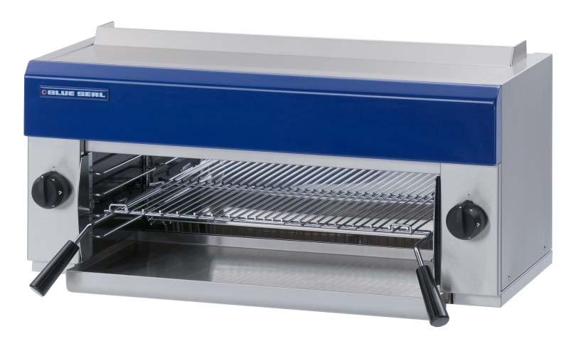
5 Specifications 1 Model Numbers Covered in this Specification G91 Blue Seal Gas Salamander External Dimensions Front Side Plan 1
6 1 Specifications Gas Supply (Non-UK models) Natural Gas Input Rating (N.H.G.C.) Supply Pressure Operating Pressure Regulator Spring LPG 31.5 MJ/hr 31.5 MJ/hr (29,850 BTU) (29,850 BTU) kpa kpa ( w.c.) 1.0 kpa (*) (4.0 w.c.) Orange ( w.c.) 2.5 kpa (*) (10.0 w.c.) Blue 1 Gas Connection /2 BSP Male Gas Supply (UK models) Natural (G20) Heat Input (Gross) Gas Rate Propane (G31) 8.8 kw 8.8 kw m /hr 0.63 kg/hr Supply Pressure 20 mbar 37 mbar Operating Pressure Regulator Used 15 mbar Yes 37 mbar No 1 Gas Connection /2 BSP Male Injector Sizes Natural Gas LPG Main burner (Non-UK models) 1.90 mm 1.20 mm Main burner (UK models) 1.65 mm 1.05 mm Pilot burner 0.30 mm 0.20 mm Salamander Internal Dimensions G91 Width Depth 685 mm 330 mm Height 230 mm (at front) Cooking Area Rack Size 610mm x 310mm Branding Plate (accessory) 610mm x 310mm Weight (Net) G91 41kg 2
7 Installation 2 Installation Requirements NOTE: It is most important that this salamander is installed correctly and that operation is correct before use. Installation shall comply with local electrical, gas, health and safety requirements. Blue Seal Salamanders are designed to provide years of satisfactory service, and correct installation is essential to achieve the best performance, efficiency and trouble-free operation. This appliance must be installed in accordance with National installation codes and in addition, in accordance with relevant National / Local codes covering gas and fire safety. AUSTRALIA: NEW ZEALAND: UNITED KINGDOM: IRELAND: - AS Gas Installations. - NZS Gas Installation. - Gas Safety (Installation & Use) Regulations BS Installation of Catering Appliances. - BS & 2 Installation Flueing & Ventilation. - IS Non - Domestic Gas Installations. Installations must be carried out by qualified service persons only. Failure to install equipment to the relevant codes and manufacturer s specifications shown in this section will void the warranty. Components having adjustments protected (e.g. paint sealed) by the manufacturer are only allowed to be adjusted by an qualified service person. They are not to be adjusted by the installation person. Unpacking Remove all packaging and transit protection from the appliance including all protective plastic coating from the exterior stainless steel panels. Check equipment and parts for damage. Report any damage immediately to the carrier and distributor. 1 x Salamander Rack. 1 x Wall Mounting Bracket, including; 1 x Trough Tray. - 2 x 25mm Black Plastic Spacers. 1 x Gas Regulator. - 2 x 3/8 Bolts / Nuts. 1 x Alternate Gas Conversion Kit. Report any deficiencies to the distributor who supplied the appliance. Check that the available gas supply is correct to that shown on the rating plate located on the front bottom corner of the right hand side panel. Check that the following parts have been supplied with the appliance: Location 1. Installation must allow for a sufficient flow of fresh air for the combustion air supply. Combustion Air Requirements Natural Gas LPG / Propane 2. 9m³/hr minimum. 9m³/hr minimum. Installation must include adequate ventilation means, to prevent dangerous build up of combustion products. 3
8 2 Installation 3. This appliance must be mounted onto a non-combustible wall or tailored stand, using the rear wall bracket and spacing screws provided. 4. Combustible walls must not protrude past the front of the appliance. 5. This appliance must not be mounted on a combustible surface or metal surface, as radiated heat will cause these surfaces to become extremely hot. Caution should be taken as intense heat is emitted at the bottom front of the appliance Components having adjustments protected (e.g. paint sealed) by manufacturer are only allowed to be adjusted by an authorised service agent. They are not to be adjusted by the installation person. 8. The unit should be mounted under an extraction hood in compliance with all local regulations. In the event that the unit is not mounted under an extraction hood, the installer must ensure that all regulations are met and that there is an unobstructed minimum distance of 750mm from the top surface of the unit to the ceiling, which must be of non-combustible material. NOTE: Do not obstruct or block the appliances flue. Never directly connect a ventilation system to the appliance flue outlet. Clearances Combustible Surface Non-Combustible Surface Left/Right hand side 100 mm 25 mm (*) Rear 30 mm (**) 30 mm (**) Top Clearance to: - Extraction Hood 200 mm - Ceiling (***) 750 mm NOTE: Only non-combustible materials can be used in close proximity to this appliance. This unit must be installed on a non-combustible wall or tailored stand with the following clearances; * ** *** We recommend allowing a clearance of 100mm on either side of the appliance to allow access to the side panels for servicing purposes. Using the wall mounting accessories provided with this appliance. Top clearance to ceiling is subject to all local regulation requirements. 4
9 Installation 2 Wall Mounting (to non-combustible wall only) 1. Fix the wall mounting bracket to the wall with six screws, in such a position that the top of the bracket is level and at least 945mm (38 ) above any surface beneath the unit. This will ensure that the bottom of the Salamander is at least 600mm (24 ) above any surface. 2. Fit the two black plastic spacers to the top rear corners of the unit. Leave them unscrewed by approximately 5mm. 3. ~ 5mm Fit the two adjusting screws / bolts into the nutserts at the bottom rear corners of the unit. These should protrude approximately 30mm from the rear of the Salamander. Fig Lift the Salamander onto the wall bracket, lining up the black plastic spacers on the salamander with the mounting notches in the bracket. ~30mm Lower the Salamander onto the mounting bracket. Fig 2 6. Tighten the black spacers securely and adjust the levelling screws/bolts to ensure that the unit is level. Fig 3 Fig 4 5

10 2 Installation Gas Connection NOTE: ALL GAS FITTING MUST ONLY BE CARRIED OUT BY A QUALIFIED SERVICE PERSON. 1. Blue Seal Salamanders do not require an electrical connection, as they function totally on the gas supply only. 2. It is essential that the gas supply is correct for the Salamander to be installed and that adequate supply pressure and volume are available. The following checks should therefore be made before installation:a. Gas Type the appliance has been supplied for, is shown on a coloured stickers located above the gas connection and next to the rating plate. Check that this is correct for the gas supply the appliance is being installed for. The gas conversion procedure is detailed in this manual. Rating Plate b. Supply Pressure required for this appliance is shown in the Specifications section of this manual. Check the gas supply to ensure adequate supply pressure exists. Fig 5 c. Input Rate of this appliance is stated on the Rating Plate and in the Specifications section of this manual. The input rate should be checked against the available supply line capacity. Particular note should be taken if the salamander is being added to an existing installation. Cap Nut NOTE: It is important that adequately sized piping runs directly to the connection joint on the appliance with as few tees and elbows as possible to give maximum supply volume. 3. Fit the gas regulator supplied, into the gas supply line as close to the appliance as possible. The regulator connections are 1/2" BSP female. Spring Adjusting Nut Regulator Spring Coloured for gas type; - Orange - Nat Gas - Blue - LPG The connection to the appliance is 1/2" BSP male. (Refer to the the Specifications section for the gas supply location dimensions). Fig 6 NOTE: A Manual Isolation Valve must be fitted to the individual appliance supply line. 4. Ensure the regulator has the correct colour spring fitted for the gas type, as detailed in the Specifications table. Opposite gas type replacement spring is part of the gas conversion kit supplied. 5. Correctly locate the appliance into its final operating position and using a spirit level, adjust the legs so that the unit is level and at the correct height. 6
11 Installation Connect gas supply to the appliance. A suitable jointing compound which resists the breakdown action of LPG must be used on every gas line connection, unless compression fittings are used. Check all gas connections for leakages using soapy water or other gas detecting equipment. WARNING: DO NOT USE A NAKED FLAME TO CHECK FOR GAS LEAKAGES. 8. Check gas operating pressure is as shown in Specifications section. 9. Adjust the regulator spring adjusting nut to set the gas operating pressure at the correct value shown in the Specifications section. NOTE: The operating pressure to be measured at the manifold test point and with all burners operating at the High Flame setting. 10. Turn off the mains gas supply and bleed the gas out of the appliance gas lines. 11. Turn on the gas supply and the appliance. 12. Verify the operating pressure remains correct (Re-adjust the regulator if required). Commissioning 1. Before leaving the new installation; a. Check the following functions in accordance with the operating instructions specified in the Operation section of the User manual. Light the Pilot Burners. Light the Main Burners. Check the Low Fire burner operation. Check the High Fire burner operation. Check the Racking System operation. b. Ensure that the operator has been instructed in the areas of correct lighting, operation, and shutdown procedure for the appliance. 2. The User manual must be kept by the owner for future reference, and a record of Date of Purchase, Date of Installation and Serial Number of Unit recorded and kept with the manual. (These details can be found on the Rating Plate attached to the R/H side panel (refer to the Gas Connection section). NOTE: If for some reason it is not possible to get the unit to operate correctly, shut off the gas supply and contact the supplier of this unit. 7

12 3 Operation NOTE: A full user s operation manual is supplied with the product and can be used for further referencing of installation, operation and service. 3.1 Description of controls 3.2 Operation Blue Seal salamanders provide two independently controlled heat zones. Lighting the pilot burners High speed grilling is provided by the two infrared gas burners in the ceiling of the grilling compartment Check that the gas supply is turned on. Push in the left gas control knob and turn to the PILOT position. 3. With the gas control knob depressed, manually light the pilot burner located in the top right and left hand sides within the cooking area of the unit. The left hand gas control knob and right hand gas control knob operate the left side and right side burners respectively, independently of each other. 4. Hold in the control knob for approximately 10 to 15 seconds, then release. Each burner is provided with a manually lit pilot burner and flame failure protection. 5. The pilot burner should remain alight. If not, repeat Items 2 to 4 above until the pilot burner lights. 6. Repeat Items 2 to 4 above with the right gas control knob to ignite the right hand pilot burner. Lighting the main burners 1. Ensure that pilot burners are alight by looking in the top right and left hand sides within the cooking area of the unit. The pilot burners will be seen burning. 2. Gas Control Knobs ๐ Rotate the control knob anti-clockwise to the position marked HIGH. 3. The main burner will now ignite automatically off the pilot burner. 4. Once lit the main burner will be burning at full rate. For a lower heat, push in the gas control knob and turn fully anti-clockwise to the LOW position. 5. Also for intermediate heat, position the control knob between the HIGH and LOW positions. OFF Position PILOT Burner HIGH Flame LOW Flame 6. Repeat Items 1 to 5 to light the second main burner. 8
13 Operation Racking Racking System The Rack System fitted to the Blue Seal Salamander is self-supporting when withdrawn, to allow easy loading of food. The installation of the rack is dependant on the cooking function required. With Branding Plate Without Branding Plate 9
14 3 Operation 3.4 Explanation of Control System Safety System Electromagnetic Flame Failure Gas Valve The purpose of the safety system is to shut off the flow of gas if the pilot flame goes out. It is comprised of the flame itself, the thermocouple, and the flame failure gas valve. The purpose of the safety valve is to shut off the flow of gas if the pilot flame goes out. Inside the body of the gas valve is an electromagnet connected to a spring loaded plunger. When the electromagnet is energized, it holds the plunger in, allowing gas to flow through the valve. When the electromagnet is de-energized, the plunger snaps to the closed position, stopping the flow of gas. The pilot flame is lit by holding in the gas control knob, which in turn temporarily pushes the plunger inside the safety valve open and allows gas to flow through. Once the burner is lit, the thermocouple will begin to generate millivolts (after about 10 to 30 seconds of being heated) and will energize the electromagnet inside the gas valve. Once energized the electromagnet holds the plunger inside the gas valve in the open position. The plunger has to have been pushed all the way in for the electromagnet to be able to hold it in place. If the burner flame goes out for some reason, the thermocouple will cool after about 10 to 30 seconds and stop generating millivolts. The electromagnet will then de-energize, and the plunger will snap shut, cutting off the flow of gas. Thermocouple Electromagnet Plunger Gas flow Shaft Knob Detail of each component in the safety system is explained below. Gas flow Plunger Thermocouple The thermocouple is a device that generates electricity when heat is applied to the tip. Insulator Internal Wire Nut Conductor Figure 3.4b Tip Millivolts are provided to the electromagnet by the thermocouple (not shown) which generates millivolts when heated. The thermocouple screws into a fitting at the back of the gas valve to make an electric connection. By pressing in the gas control knob, the plunger can be temporarily held open while lighting. There's two reasons for this; gas has to flow through the safety valve to make it possible to light the pilot burner, and secondly the plunger has to be pushed all the way in for the electromagnet to hold it in. I.e.; the electromagnet is strong enough to hold the plunger in once there, but is not strong enough to pull it in by itself. Sometimes a problem with the flame not staying lit after releasing the button can be attributed to not pushing the plunger all the way in. Figure 3.4a The tip of the thermocouple is located in the pilot burner flame, and the nut at the other end of the thermocouple screws into the back of the gas valve. Inside the copper tubing is a wire which is joined at the tip but insulated from the rest of the tubing. These two parts (the copper tubing and wire) make up the "wiring" for an electrical circuit. When these two dissimilar metals, wire and tip, are heated an electrical voltage is produced. This type of thermocouple generates between 7 and 30 millivolts when heated in the pilot flame. 10
15 Cleaning / Maintenance 4 CAUTION: Always turn off the gas supply before cleaning. This unit is not water proof. Do not use water jet spray to clean interior or exterior of this unit. 4.1 Cleaning General Enamelled surfaces To achieve the best results, cleaning must be thorough, and all controls and mechanical parts checked and adjusted periodically by a competent serviceman. If any small faults occur, have them attended to promptly. Don't wait until they cause a complete breakdown. Do not use wire brushes, steel wool or other abrasive material. Clean the enamelled surfaces regularly with a good quality domestic oven cleaner. Remove the rack and side racks from the Salamander - this allows easy cleaning of the flat enamelled side walls. Leave the tray in to collect all residue. Racking Grease / Crumb Tray For ease of cleaning of this unit and the racking system and to achieve the best results, it is recommended that the racking is removed completely from the unit and cleaned independently This will allow for a more thorough cleaning of the Salamander. Empty and clean daily. To remove the racking system, carry out the following instructions. Remove the Grease / Crumb Tray from the underside of the salamander unit. Remove the Branding Plate from the rack (If fitted). Slide the rack out of the side racks and remove from the unit. Stainless surfaces Clean with detergent. Baked on deposits or discolouration may require a good quality stainless steel cleaner or stainless steel wool. Always apply the cleaner when the Salamander is cool and rub in the direction of the "grain". 11
16 5 Trouble-shooting WARNING: 5.1 ALL INSTALLATION AND SERVICE REPAIR WORK MUST BE CARRIED OUT BY QUALIFIED PERSONS ONLY. Trouble-shooting chart Fault Pilot won t light Possible Cause Knob on gas control won t go fully in. Remedy Remove obstruction. Correct control panel mounting. Replace gas control. (Refer service section 6.2.6) Pilot flame small No gas supply. Ensure gas is connected and on (bottles not empty). Gas pressure too low. Check gas supply pressure. (Refer specifications section) Blocked pilot injector. Clean or replace pilot injector. (Refer service section 6.2.3) Gas pressure too low. Check gas supply pressure. (Refer specifications section) Pilot injector restricted. Clean or replace pilot injector. (Refer service section 6.2.3) Pilot goes out when knob released Releasing knob before the thermocouple is heated. Hold control in for longer (10 s), see if pilot will stay lit. Pilot flame too small. Correct fault. (Refer fault:pilot Flame Small) Pilot goes out when main burner comes on Main burners will not light Thermocouple faulty. (Refer fault diagnosis 5.2.1) Replace thermocouple. (Refer service section 6.2.1) Gas magnet faulty. (Refer fault diagnosis 5.2.1) Replace gas magnet. (Refer service section 6.2.7) Incorrect gas pressure. Check supply / adjust pressure. (Refer specifications section) Faulty gas control. Replace gas control. (Refer service section 6.2.6) Wrong size or blocked injectors. Replace / clean injectors. (Refer service section 6.2.5) Small pilot flame. Correct fault. (Refer fault:small Pilot Flame) Incorrect supply pressure. Check supply correct pressure. Faulty gas control. Replace gas control. (Refer service section 6.2.6) 12
17 Trouble-shooting Fault Burner flame incorrect colour / flame not stable Possible Cause Incorrect supply pressure. 5 Remedy Check supply pressure. Pilot too small. Correct fault. (Refer fault: Pilot flame small) Incorrect injector sizes. Check injector sizes and replace if necessary. (Refer service section 6.2.5) Injector blocked. Clean injector. (Refer service section 6.2.5) Burner popping / blow back Gas leak in burner plaque. (Refer fault diagnosis 6.1.2) Replace burner. (Refer service section 6.2.4) Lack of glowing. Large haze beneath burner Incorrect gas supply pressure. Check the gas pressure at the pressure test point. 13
18 5 Trouble-shooting 5.2 Fault Diagnosis Pilot drops out when gas knob released Pilot flame too small If pilot can be lit but the flame is too small to impinge on the thermocouple, then check the gas pressure. If ok, remove pilot injector from pilot burner and check for blockages and/or correct size. Thermocouple faulty Check thermocouple connection to gas control is firm (loose connections will cause resistance in millivolt circuit and result in pilot outage). If connection is OK, then disconnect the thermocouple from the rear of the gas control, light the pilot, and whilst holding the control knob in, and measure voltage between the thermocouple and earth (e.g. the body of the gas control). This should read approximately 30mV. If this reading is less than 10mV then the thermocouple is faulty replace. Gas magnet faulty If thermocouple milli-voltage is above 10mV, and the pilot still will not hold, then the gas magnet is faulty - replace Burner popping / Blow back Gas leak in burner plaque With burner operating check for hairline cracks (these appear as brighter orange lines on burner tiles). If visible, replace burner. 14
19 Service Procedures Section 6 Page Number 6.1 Access Control Panel Side Panel Replacement Thermocouple...16 Pilot Burner...16 Pilot Injector...17 Main Burner...17 Main Burner Injectors...18 Gas Control Valve...18 Gas Control Magnet Adjustment Gas Control Re-greasing...19 Low Fire Screw Adjustment...19 ALL INSTALLATION AND SERVICE REPAIR WORK MUST BE CARRIED OUT BY QUALIFIED PERSONS ONLY. WARNING: ENSURE GAS SUPPLY IS SWITCHED OFF BEFORE SERVICING ALWAYS CHECK / TEST FOR GAS LEAKS AFTER SERVICE REPAIRS ON THE GAS SYSTEM 15
 Remove the side panel (refer 6.1.2). 2) Undo the two screws at the bottom of the control panel, and remove.")
 Undo the clamp on the pilot burner holding the thermocouple in place (secured by one screw).")
 Undo the two screws near the bottom of the side panel to be removed. Figure 6.2.1 2) Lift the side panel and remove from the salamander.")
")
20 6 Service Procedures 6.1 Access Control 6.2 Replacement panel Thermocouple 1) Remove control knob. 1) Remove the side panel (refer 6.1.2). 2) Undo the two screws at the bottom of the control panel, and remove. 2) Unscrew the thermocouple from the rear of the gas control. 3) Undo the clamp on the pilot burner holding the thermocouple in place (secured by one screw). Withdraw the thermocouple from the pilot assembly. 4) Replace and reassemble in reverse order. Clamp Two screws Figure Side panel 1) Undo the two screws near the bottom of the side panel to be removed. Figure ) Lift the side panel and remove from the salamander. IMPORTANT: WHEN SCREWING THERMOCOUPLE BACK INTO THE GAS CONTROL, ONCE THREADED UP, TIGHTEN UP ANOTHER ¼ TURN ONLY. DO NOT OVER TIGHTEN Pilot burner 1) Remove the side panel (refer 6.1.2) 2) Undo the pilot supply tube from either the pilot burner or the gas control valve. Two screws Figure Pilot supply tube Figure 6.2.2a 16
 Extract the injector from the pilot burner, taking care not to lose the spring. 5) Replace or clean the injector as necessary. When reassembling, ensure that the injector is fully screwed in.")
 Fit new pilot burner to bracket, and re-assemble in reverse order. 6) Ensure that the correct size pilot injector is fitted to the pilot burner: Spring Pilot Nat Gas 0.30mm LPG 0.")
 Remove the burner guard by pulling it down from the centre fastenings and then removing it from the mounting holes in the side wall.")
21 6 Service Procedures 3) Undo the clamp on the pilot burner holding the thermocouple in place (secured by one screw). Withdraw the thermocouple from the pilot assembly. Clamp Pilot Screw Cap Figure 6.2.3a 4) Extract the injector from the pilot burner, taking care not to lose the spring. 5) Replace or clean the injector as necessary. When reassembling, ensure that the injector is fully screwed in. Figure 6.2.2b 4) Unclip the burner guard, then remove the two screws securing the pilot bracket (inside salamander). Withdraw the pilot burner and bracket. 5) Fit new pilot burner to bracket, and re-assemble in reverse order. 6) Ensure that the correct size pilot injector is fitted to the pilot burner: Spring Pilot Nat Gas 0.30mm LPG 0.20mm Injector Cap Figure 6.2.3b Refer to section below for pilot injector replacement Main burner 1) Remove the side panel (refer 6.1.2). 2) Remove the burner guard by pulling it down from the centre fastenings and then removing it from the mounting holes in the side wall. 3) Remove the two centre fixing screws and remove the centre bracket. Burner guard Two screws Two screws Figure 6.2.2c Pilot injector 1) Remove the side panel (refer 6.1.2) 2) Undo the cap from the rear of the pilot burner to give access to the injector. Figure 6.2.4a 3) Unscrew the pilot injector. 17
 Remove the side panel (refer 6.1.2), and remove the knob from the gas control. 2) Disconnect the thermocouple, pilot supply tube, and main burner supply tube from the gas control.")
 Replace and reassemble in reverse order 6.2.5 Main burner injectors 1) Remove the side panel (refer 6.1.2). 2) Unscrew the main burner injector. Figure 6.2.6 6.2.7 Gas control magnet 1) Remove side panel (refer 6.")
22 6 Service Procedures ) Holding the burner, remove the two screws located in the control area which fix to the burner flange. The burner can now be removed. Gas control valve 1) Remove the side panel (refer 6.1.2), and remove the knob from the gas control. 2) Disconnect the thermocouple, pilot supply tube, and main burner supply tube from the gas control. 3) Undo the nut securing the gas control inlet to the supply manifold. Two screws 4) Extract the gas control, reassemble in reverse order. replace and Figure 6.2.4b 5) Replace and reassemble in reverse order Main burner injectors 1) Remove the side panel (refer 6.1.2). 2) Unscrew the main burner injector. Figure Gas control magnet 1) Remove side panel (refer 6.1.1). 2) Unscrew the thermocouple from the rear of the gas control. Injector 3) Remove the rear nut from the gas control. 6) Extract gas magnet. 7) Replace and reassemble in reverse order. Figure ) Clean or replace injector and reassemble in reverse order. NOTE: It is important that the injector aligns centrally with the burner venturi. Gas Control Magnet Rear Nut Figure
 Remove 2 screws holding shaft plate to gas control body and remove control shaft and plate. Note orientation of shaft for correct re-assembly. 2) Pull off the gas control knob.")
23 Service Procedures Adjustment / Calibration Gas control re-greasing ) Isolate gas supply Low fire rate adjustment 1) Light the burner and turn the control to the low flame position. 2) Remove 2 screws holding shaft plate to gas control body and remove control shaft and plate. Note orientation of shaft for correct re-assembly. 2) Pull off the gas control knob. 3) Adjust low fire screw (located at the top left of the gas valve) to achieve an even, low burn across the salamander burner. The recommended factory settings are: LPG Nat ¼ turn out 1 turn out Two Screws Figure 6.3.1a 3) Using needle nose pliers or similar, pull out gas control spindle, again noting its orientation. Low fire screw 4) Apply a suitable high temperature gas cock grease or lubricant such as ROCOL - A.S.P (Anti scuffing paste) to the outside of the spindle. Figure ) Paint-seal the low fire screw, and replace the control knob. 5) Replace spindle and re-assemble gas control in reverse order. Spindle Figure 6.3.1b 19

 Wall mounting")
 Branding")
24 7 Accessories Salamander rack (017963) Rack handle (013395) Wall mounting bracket (026096) Side rack (026093) Branding plate (013418) 20
25 Exploded Parts Diagrams 8.1 G91 8 Main Assembly Item Part No Description WALL MOUNTING BRACKET BACK PANEL FLUE END RH SIDE PANEL FRONT COVER CONTROL PANEL TRAY SUPPORT BLUE SEAL BADGE FLUE END LH 21
26 8 Exploded Parts Diagrams 8.2 G91 Gas Assembly Item Part No Description K INFRA-RED BURNER MANIFOLD PILOT MOUNTING BRACKET RH INJECTOR MOUNTING BRKT INJECTOR SUPPLY TUBE PILOT SUPPLY TUBE RH BURNER RETAINING CHANNEL BURNER GUARD KNOB BSEAL 8mm GAS PF GAS CONTROL INJECTOR 1.90mm (NAT GAS) INJECTOR 1.20mm (LPG) INJECTOR 1.65mm (UK NAT GAS) INJECTOR 1.05 mm (UK PROPANE) THERMOCOUPLE 450MM PILOT INJECTOR SIT Ø0.30mm NAT PILOT INJECTOR Ø0.20mm LPG/PROPANE K PILOT SIT 100 SERIES KIT K PILOT SIT 100 SERIES KIT PILOT SUPPLY TUBE 22
27 Exploded Parts Diagrams G91 Racking Assembly Item Part No Description SIDE RACK WA - SALAMANDER SIDE RACK SCREW RACK HANDLE RACK TROUGH TRAY WA 23
28 9 Service Contacts Australia VICTORIA - MOFFAT PTY HEAD OFFICE AND MAIN WAREHOUSE 740 Springvale Road Mulgrave VIC 3170 Spare Parts Department Tel (03) Fax (03) Free Call Fax (03) NEW SOUTH WALES - MOFFAT PTY Unit 3/142 James Ruse Drive Rosehill NSW 2142 Spare Parts Tel (02) Free Call Fax (03) QUEENSLAND - MOFFAT PTY 30 Prosperity Place Geebung QLD 4034 Spare Parts Tel (07) Free Call Fax (03) WESTERN AUSTRALIA - MOFFAT PTY 67 Howe St Osbourne Park, WA 6017 Spare Parts Tel (08) Fax (08) Free Call Fax (03) NATIONAL COVERAGE FOR 24 HOUR SERVICE OR MAINTENANCE DIAL FREE CALL (AUSTRALIA ONLY) Canada SERVE CANADA 22 Ashwarren Rd Downview Fax Ontario M3J1Z5 Tel New Zealand CHRISTCHURCH - MOFFAT LTD 16 Osborne St PO Box Christchurch Spare Parts Tel (03) Fax (03) Free Call 0800 MOFFAT ( ) Fax (03) AUCKLAND - MOFFAT LTD 4 Waipuna Road Mt Wellington Auckland Spare Parts Tel (09) Fax (09) Free Call 0800 MOFFAT ( ) 24
29 Service Contacts 9 United Kingdom Utensils Direct Utensils Direct
30 A Appendix A: Mounting Holes 80 Mounting hole locations Base view Rear view Dimensions shown in millimetres. All mounting holes are threaded 3/8 BSW 26
31 B Appendix B: Gas Conversion Conversion Procedure C AUTION : Ensure that the Unit is isolated from the gas supply before commencing servicing NOTE: These conversions should only be carried out by qualified persons. All connections must be checked for leaks before re-commissioning the appliance. For all the following conversion instructions, the side panels have to be removed (Remove the two screws at the bottom of each side panel). All conversion details apply to both L/Hand and R/Hand burners. For all relevant gas specifications refer to the table at the end of this section. Main Burner Injectors Unscrew the main burner injectors ( 1/2 A/F). Determine the correct injector sizes for the corresponding gas type from the rating plate affixed to the right hand side panel front bottom corner. Replace with the correct size injectors. Main Burner Injector Pilot Injectors Unscrew the cap from the rear of the pilot burners, and unscrew the pilot injectors (taking care not to lose the springs). Determine the correct pilot injector sizes for the corresponding gas from the rating plate affixed to the right hand side panel front bottom corner. Replace with the correct size pilot injectors. Fig B1 NOTE: Ensure that the Pilot Injectors are fully screwed in. Pilot Injector Cap Fig B2 27
32 B Appendix B: Gas Conversion Gas Regulator 1. Ensure that the gas supply is turned off. 2. Unscrew the slotted cap from the regulator. 3. Unscrew the spring adjusting nut and remove the spring. 4. Fit the correct colour spring for the gas type being used and screw in the spring adjusting nut Turn on the gas supply and the appliance. Adjust the spring adjusting nut to achieve the correct operating pressure. Cap Nut Spring Adjusting Nut Regulator Spring Coloured for gas type; - Orange - Nat Gas - Blue - LPG NOTE: The operating pressure to be measured at the manifold test point and with all burners operating at the High Flame setting. 7. Turn off the mains gas supply and bleed the gas out of the appliance gas lines. 8. Turn on the gas supply and the appliance. 9. Verify the operating pressure remains correct (Re-adjust the regulator if required). 10. Screw the cap back into the regulator. Fig B3 Gas Type Identification Label On completion of the gas conversion, replace the gas type identification labels, located at:- The rear of the unit, above the gas entry port. - Beside the rating plate. Low Fire Adjustment NOTE: If the salamander is fitted with the Adjustable Racking System, this has to be removed to enable the 2 front control panels to be removed. Refer to the Cleaning Section for information on how to remove and refit the Adjustable Racking System Remove the gas control knobs from the front of the unit. Remove the 2 front control panels by removing the two screws (per panel) located at the bottom of each panel. Set the burner low fire adjustment. The low fire screw on the gas control valve should be screwed fully in, then unscrewed by the measurement shown in the Gas Specifications table. NOTE: The Low Fire Screw should be sealed with coloured paint on completion of the low fire adjustment. Low Fire Adjustment Fig B4 28
33 Appendix B: Gas Conversion B Commissioning Before leaving the converted installation; 1. Check all gas connections for leakages using soapy water or other gas detecting equipment. WARNING: DO 2. NOT USE A NAKED FLAME TO CHECK FOR GAS LEAKAGES. Check the following functions in accordance with the operating instructions specified in the Operation section of the User manual. Light the Pilot Burners. Light the Main Burners. Check the Low Fire burner operation. Check the High Fire burner operation. Ensure all controls operate correctly. NOTE: If for some reason it is not possible to get the unit to operate correctly, shut off the gas supply and contact the supplier of this unit. Gas Specifications - Non UK Only: Natural Gas (G20) LP Gas (Propane) (G31) Main Burner Injectors Ø 1.90 mm Ø 1.20 mm Pilot Burner Injectors Ø 1.00 mm Ø 1.00 mm 2 turns out (ccw) ½ turn out (ccw) 1.00 kpa (*) 2.50 kpa (*) Orange Blue Size Low Fire: Adjustment Operating Pressure Regulator Spring - UK Only: Natural Gas (G20) Propane (G31) Main Burner Injectors Ø 1.65 mm Ø 1.05 mm Pilot Burner Injectors Ø 1.00 mm Ø 1.00 mm 1 turn out (ccw) ¼ turn out (ccw) 15 mbar (*) 37 mbar Yes No Low Fire: Size Adjustment Operating Pressure Regulator Used NOTE: * The burner operating pressure is to be measured at the manifold test point with all burners operating at full setting. The operating pressure is ex-factory set and not to be adjusted, apart from when converting between gases, if required. (Refer to the Gas Conversion section for details). 29
INSTALLATION AND OPERATION MANUAL GAS SALAMANDER G91 G91B. For use in GB & IE
 INSTALLATION AND OPERATION MANUAL GAS SALAMANDER G91 G91B For use in GB & IE 234060-3 MANUFACTURED BY Moffat Limited Christchurch New Zealand INTERNATIONAL CONTACTS AUSTRALIA Moffat Pty Limited Web: www.moffat.com.au
-2- MANUFACTURED BY. Moffat Pty Limited. P O Box Christchurch New Zealand Ph: (03) Fax: (03) WORLD-WIDE BRANCHES
 Fax: (03) WORLD-WIDE BRANCHES") G59 BARBEQUE -1- MANUFACTURED BY Moffat Limited P O Box 10-001 Christchurch New Zealand Ph: (03) 3891-007 Fax: (03) 3891-276 WORLD-WIDE BRANCHES UNITED KINGDOM Blue Seal Units 6-7, Mount Street Business
G59 BARBEQUE -1- MANUFACTURED BY Moffat Limited P O Box 10-001 Christchurch New Zealand Ph: (03) 3891-007 Fax: (03) 3891-276 WORLD-WIDE BRANCHES UNITED KINGDOM Blue Seal Units 6-7, Mount Street Business
Gas Fryers GT45 / GT46 / GT60. Service Manual. Revision 1/
 Gas Fryers GT45 / GT46 / GT60 Service Manual 1 WARNING: ALL INSTALLATION AND SERVICE REPAIR WORK MUST BE CARRIED OUT BY QUALIFIED PERSONS ONLY. IMPORTANT: MAKING ALTERATIONS MAY VOID WARRANTIES AND APPROVALS.
GAS BBQ 4 burner. instructions for. model no: BBQ10
 instructions for GAS BBQ 4 burner model no: BBQ10 Thank you for purchasing a Sealey product. Manufactured to a high standard, this product will, if used according to these instructions, and properly maintained,
VULCAN GAS SALAMANDER MODEL SG-G
 VULCAN GAS SALAMANDER MODEL SG-G Index: General Data 2 Owners Responsibility 3 Authorised Vulcan Catering Equipment Branches And Dealers 3 Parts Ordering / Service Information 4 Prior to Installation Of
INSTRUCTION MANUAL. Gas Salamander
 INSTRUCTION MANUAL Gas Salamander This manual contains important information regarding your unit. Please read this manual thoroughly prior to equipment set-up, operation and maintenance. Failure to comply
RADIANT GAS BROILER VULCAN MODEL RGB-8
 RADIANT GAS BROILER VULCAN MODEL RGB-8 Index: General Data 2 Owner s Responsibility 3 Authorised Vulcan Catering Equipment Branches and Dealers 3 Parts Ordering / Service Information 4 Prior to Installation
Gas Countertop Hot Plates
 Gas Countertop Hot Plates This manual contains important information regarding your Patriot unit. Please read the manual thoroughly prior to equipment set-up, operation and maintenance. Failure to comply
SERVICE MANUAL SALAMANDER BROILERS RADIANT AND INFRARED 36RB 36IRB VULCAN C36RB C36IRB WOLF
 SERVICE MANUAL SALAMANDER BROILERS RADIANT AND INFRARED VULCAN 36RB 36IRB WOLF C36RB C36IRB This Manual is prepared for the use of trained Vulcan Service Technicians and should not be used by those not
Standard Gas Countertop Griddle
 Standard Gas Countertop Griddle This manual contains important information regarding your unit. Please read the manual thoroughly prior to equipment set-up, operation and maintenance. Failure to comply
USE AND ASSEMBLY INSTRUCTIONS
 USE AND ASSEMBLY INSTRUCTIONS Model: HSQ-A213S; HSQ-B213S; HSQ-A214S; HSQ-B214S; HSQ-A215S; HSQ-B215S; HSQ-A216S; HSQ-B216S HSQ-A213S HSQ-A214S HSQ-A215S HSQ-A216S FOR OUTDOOR USE ONLY PLEASE READ INSTRUCTIONS
User, Installation, Servicing and Conversion Instructions. Opus 700 Gas Chargrills OG7401, OG7402, OG7403 & OG7404
 User, Installation, Servicing and Conversion Instructions Opus 700 Gas Chargrills OG7401, OG7402, OG7403 & OG7404 Please make a note of your product details for future use: Date Purchased: Model Number:
VULCAN 6 BURNER FLAT TOP GAS GRIDDLE FLOOR STANDING MODEL FTG-10G
 VULCAN 6 BURNER FLAT TOP GAS GRIDDLE FLOOR STANDING MODEL FTG-10G Index: General Data 2 Owner s Responsibility 3 Authorised Vulcan Catering Equipment Branches and Dealers 3 Parts Ordering / Service Information
APPROVED FOR USE IN SOUTH AFRICA STAINLESS STEEL STOVE
 AUTOMATIC GAS COOKER TWO BURNER STAINLESS STEEL STOVE THIS IS A LOW PRESSURE APPLIANCE TO BE USED ONLY WITH A 2.8kPa APPROVED SANS 1237 REGULATOR. REGULATOR NOT INCLUDED. PLEASE READ THESE INSTRUCTIONS
Gas Countertop Griddle
 Gas Countertop Griddle This manual contains important information regarding your purchased equipment. Please read the manual thoroughly prior to equipment set-up, operation and maintenance. Failure to
LNVx Gas Conversion Kit Instructions
 TB134 Issue 1.0 Nov 2018 Applies to models: LNVx LNVx Gas Conversion Kit Instructions +44 (0) 1460 53535 info@powrmatic.co.uk www.powrmatic.co.uk General Information Heater conversion between gases will
13kW Patio Heater. Assembly & User Instructions
 13kW Patio Heater Assembly & User Instructions GUARANTEE The Memphis patio heater is made by Universal Innovations to an exacting quality standard and is covered by the following guarantee: THIS PRODUCT
Operator Manual Gas Griddle / Cheesemelter
 Operator Manual Gas Griddle / Cheesemelter HDB2031 & HDB2042 Model: HDB2042 Table of Contents Safety Information...2 Unpacking...3 Installation...3 Lighting Instructions...3 Preparing Griddle...4 Operation...4
INSTALLATION INSTRUCTIONS MANUAL ON/OFF SAFETY VALVE/PILOT KIT MODEL GA9050A-1 (F0235)
") P/N 126905-01 Rev. B 11/2016 INSTALLATION INSTRUCTIONS MANUAL ON/OFF SAFETY VALVE/PILOT KIT MODEL GA9050A-1 (F0235) For All Single, Dual and Triple Burner Natural and Propane/LP Gas Logs P126905-01 For
P/N 126905-01 Rev. B 11/2016 INSTALLATION INSTRUCTIONS MANUAL ON/OFF SAFETY VALVE/PILOT KIT MODEL GA9050A-1 (F0235) For All Single, Dual and Triple Burner Natural and Propane/LP Gas Logs P126905-01 For
Propane Conversion Kit Instruction
 Propane Conversion Kit Instruction Condensing gas boiler Required Input Rates Logamax plus GB62-80 kw 270,000 btu/hr Logamax plus GB62-00 kw 35,000 btu/hr This kit and instructions are for converting the
INSTALLATION & OPERATION MANUAL RCT RCR. Open Burner, Griddle & Oven Range. Trueheat RCT & RCR IO Manual Page 1 of 20
 INSTALLATION & OPERATION MANUAL RCT RCR Open Burner, Griddle & Oven Range Trueheat RCT & RCR IO Manual Page 1 of 20 CONGRATULATIONS! Thank you for choosing Trueheat. This product has been specifically
Installation and Operating Instructions
 Installation and Operating Instructions For Single Burner Outdoor BBQ Models Outback RV Explorer and Bushman RV Explorer. IMPORTANT: READ THIS DOCUMENT THOROUGHLY BEFORE USING YOUR SOVEREIGN RV EXPLORER
Operator: Save these instructions for future use!
 WHITE-RODGERS Type 36C04, 36C14 Step-Opening Combination Gas Control (24 Volt, 120 Volt & 750 mv Models) INSTALLATI INSTRUCTIS Operator: Save these instructions for future use! FAILURE TO READ AND FOLLOW
INSTALLATION & OPERATION MANUAL FOR Stockpot Range
 INSTALLATION & OPERATION MANUAL FOR Stockpot Range MODELS MLS VSP100 ML-052822 VSP200 ML-052823 VSP200F ML-769292 www.vulcanhart.com MODELS MLS WSPR1 ML-760600 WSPR2 ML-760601 WSPR2F ML-769292 www.wolfrange.com
CALGARY BBQ MODEL#GB7540S
 SS350 CLGRY BBQ MODEL#GB7540S EN-GB7540S-1401 GB7540S 1 2 3 4 5 25 24 23 22 21 20 19 18 6 7 8 9 10 11 12 13 17 16 15 14 26 6 B C D E F Bolt M6x10 Nut M8 Bolt M4x20 Nut M6 Bolt ST4.2x10 C C M4x20 2PCS (C)
Propane Conversion Kit Instructions
 604 8 0/ US/CA For heating engineers Propane Conversion Kit Instructions Logano G4 X gas-fired boiler This conversion kit and the accompanying instructions are for conversion of G4 X gas-fired boilers
TB132. Gas Conversion Kits for NV & NVS Heaters. Issue 1.0 May Applies to models: NV & NVS
 TB132 Issue 1.0 May 2018 Applies to models: NV & NVS Gas Conversion Kits for NV & NVS Heaters www.powmatic.co.uk +44 (0) 1460 53535 info@powrmatic.co.uk General Information Heater conversion between gases
INSTALLATION, OPERATION, SERVICE & PARTS MANUAL FOR STOCK POT RANGE MODELS VSP100, VSP200 & VSP300
 INSTALLATION, OPERATION, SERVICE & PARTS MANUAL FOR STOCK POT RANGE MODELS VSP100, VSP200 & VSP300 MODEL VSP100 VULCAN-HART COMPANY, P.O. BOX 696, LOUISVILLE, KY 40201-0696, TEL. (502) 778-2791 FORM 30780
Operator: Save these instructions for future use!
 WHITE-RODGERS 36C53 Combination Gas Valves (24 Volt Model) INSTALLATI INSTRUCTIS Electrical Rating: Voltage: 24 Volts, (30 Volts Max.), 60 Hz. Current Rating: 0.23 Amps Type of Gas Natural Gas Pressure
Operator: Save these instructions for future use!
 WHITE-RODGERS Type 36C67 Combination (24 Volt Models) INSTALLATION INSTRUCTIONS Operator: Save these instructions for future use! FAILURE TO READ AND FOLLOW ALL INSTRUCTIONS CAREFULLY BEFORE INSTALLING
ASSEMBLY INSTRUCTIONS HOODED GAS GRILL. Model:KYQ-BFT402
 ASSEMBLY INSTRUCTIONS HOODED GAS GRILL Model:KYQ-BFT402 FOR OUTDOOR USE ONLY PLEASE READ INSTRUCTIONS CAREFULLY BEFORE ASSEMBLY RETAIN THIS MANUAL FOR FUTURE REFERENCE 1 WARNING Hazardous fire or explosion
USER MANUAL Wok Range
 Wok Range MODEL: 351CPGWOK(LP/NG) 05/2018 This user s manual contains information and guidelines collected from years of industry experience. For optimal safety and efficient operation, please make this
Operator: Save these instructions for future use!
 Pilot Gas Outlet: Located at outlet end of the valve Type of Gas Suitable for all domestic heating gases Pressure Rating: 1/2 lb. per sq. in. Pressure Regulator Adjust Range (Typical, See Control Label):
Important: Retain these instructions for future use.
 CATERER 4 & 6 BURNER BBQ Model No. BQ1050 Model No. BQ1051 Ideal heavy duty BBQ for sporting and social clubs or anywhere large groups are entertained Solid 5mm thick steel hotplate Castors for easy moving
Propane Conversion Kit Instruction
 Propane Conversion Kit Instruction Condensing gas boiler Required Input Rates GB142-24 84,800 btu/hr GB142-30 106,000 btu/hr GB142-45 160,900 btu/hr GB142-60 214,800 btu/hr This kit and instructions are
3. SPECIFICATION 4. ASSEMBLY
 INSTRUCTIONS FOR GAS BBQ STAINLESS STEEL 5 BURNER + SIDE BURNER MODEL NO: BBQ12 Thank you for purchasing a Sealey product. Manufactured to a high standard, this product will, if used according to these
INSTALLATION GUIDE Gas Rangetops
 INSTALLATION GUIDE Gas Rangetops Contents Wolf Gas Rangetops........................... 3 Safety Instructions............................ 4 Gas Rangetop Specifications.................... 5 Gas Rangetop
Important: Retain these instructions for future use.
 Model No. BQ1076 Powerful 8MJ/h stainless steel burner for true BBQ performance Piezo ignition for easy lighting Generous cooking area of 45 x 29cm Reversible satin enamel cast iron cooking surface Complete
Propane Conversion Kit Instruction
 Propane Conversion Kit Instruction Condensing gas boiler Required Input Rates GB42-24 84,800 btu/hr Tab. GB42-30 06,000 btu/hr GB42-45 49,000 btu/hr GB42-60 24,800 btu/hr This kit and instructions are
36E DSI, HSI & Proven Pilot Two-Stage Combination Gas Valve INSTALLATION INSTRUCTIONS
 INLET PRESS TAP WTE-RODGERS 36E96-314 DSI, HSI & Proven Pilot Two-Stage Combination Gas Valve INSTALLATION INSTRUCTIONS Operator: Save these instructions for future use! FAILURE TO READ AND FOLLOW ALL
Dual Solenoid Gas Valve Installation
 Installation IMPORTANT: These instructions are intended as a guide for qualified personnel installing or servicing FLYNN Gas Products. Carefully follow all instructions in this bulletin and all instructions
GM-7000 Series CE Approved Gas Control Valve
 Installation Instructions GM-7000 Issue Date November 9, 2012 GM-7000 Series CE Approved Gas Control Valve Installation IMPORTANT: These instructions are intended as a guide for qualified personnel installing
INSTALLATION & OPERATION MANUAL FOR Teppan-Yaki Griddles
 INSTALLATION & OPERATION MANUAL FOR Teppan-Yaki Griddles MODELS MLS TYG48C ML-769368-Z1 TYG60C ML-766505-Z www.wolfrange.com TYG48C ITW Food Equipment Group, LLC An Illinois Tool Works Company 3600 North
Instructions for High Altitude Conversion
 6304 38 0/ US/CA For heating engineers Instructions for High Altitude Conversion Logano G334 X gas-fired boiler This conversion kit and the accompanying instructions are for conversion of G334 X gas-fired
Operator: Save these instructions for future use!
 INLET PRESS TAP WHITE-RODGERS 36E93-304 Delay-Opening Combination Gas Valve INSTALLATION INSTRUCTIONS Operator: Save these instructions for future use! FAILURE TO READ AND FOLLOW ALL INSTRUCTIONS CAREFULLY
WARNING. Gasmate is a registered trademark of: Sitro Group Australia Pty Ltd Aber Ltd - Hamilton, N.Z.
 GALAXY DROP IN BBQ Model NO. BQ1096 Premium #304 grade stainless steel construction Rotary ignition Satin enamel cast iron reversible plate and stainless steel grill Convenient lid gives you extra bench
36E DSI and HSI Two-Stage Combination Gas Valve INSTALLATION INSTRUCTIONS
 INLET PRESS TAP WTE-RODGERS 36E54-214 DSI and HSI Two-Stage Combination Gas Valve INSTALLATION INSTRUCTIONS Operator: Save these instructions for future use! FAILURE TO READ AND FOLLOW ALL INSTRUCTIONS
SEQUENTIAL SHOWER VALVE INSTRUCTION MANUAL PLEASE LEAVE THIS MANUAL WITH THE END USER
 SEQUENTIAL SHOWER VALVE INSTRUCTION MANUAL PLEASE LEAVE THIS MANUAL WITH THE END USER CONTENTS 1. INTRODUCTION & SAFETY 1 2. DIMENSIONS 2 3. TECHNICAL DATA 3 4. OPERATION 4 5. COMPONENTS 5 6. SITE INSTALLATION
Your safety and the safety of others are very important.
 NATURAL GAS TO PROPANE CONVERSION KIT ALPKT57- INSTALLATION INSTRUCTIONS PROPANE CONVERSION KIT SAFETY... INSTALLATION REQUIREMENTS... Tools and Parts... LP Gas Requirements... Table of Contents INSTALLATION
The conversion of new certified central heating gas appliances must conform to directions outlined in this instruction.
 ACCESSORY KIT INSTALLATION INSTRUCTIONS HIGH ALTITUDE APPLICATION CONVERSION MID-EFFICIENCY SINGLE-STAGE INDUCED COMBUSTION FURNACES MODELS: P*HU/G8T-UH/L8T-UH/FL8 UPFLOW / HORIZONTAL P*DN/G8T-DN/L8T-DN
installation instructions
 installation instructions GAS CONVERSION KIT PROPANE-TO-NATURAL P/N 315572-71201 4GAD 6GAD Cancels: IIK 4G-50-4 IIK 4G-50-5 7/15/91 NOTE: Read the entire instructions before starting the installation.
Installation Instructions
 48011HW NATURAL GAS TO PROPANE CONVERSION KIT 58HDX, 359AAV, PG9YAB, PG9YAA Installation Instructions SAFETY REQUIREMENTS Installing and servicing heating equipment can be hazardous due to gas and electrical
36E03 and 36E38 DSI and HSI Step Opening Combination Gas Valve INSTALLATION INSTRUCTIONS
 INLET PRESS TAP WHITE-RODGERS 36E03 and 36E38 DSI and HSI Step Opening Combination Gas Valve INSTALLATION INSTRUCTIONS Operator: Save these instructions for future use! FAILURE TO READ AND FOLLOW ALL INSTRUCTIONS
BP48-1 AND SSP48-1 IN-GROUND POST INSTALLATION INSTRUCTIONS
 BP48-1 AND SSP48-1 IN-GROUND POST INSTALLATION INSTRUCTIONS WARNING: THIS IN-GROUND POST IS NOT DESIGNED FOR USE WITH AN LP GAS CYLINDER. WARNING: SEE YOUR GRILL OWNER S MANUAL FOR PROPER LOCATION, MINIMUM
SUMMITTM 400 & 600. Natural Gas Barbecues. Step-By-Step Guide
 SUMMITTM 400 & 600 Natural Gas Barbecues Step-By-Step Guide W E B E R W E B E R W E B E R W E B E R Summit 400 NG Summit 600 NG CANADIAN GAS ASSOCIATION R A P P R O V E D WARNING: Follow all leak check
BFM 2 AND 4 BURNER BBQ MANUAL
 BFM 2 AND 4 BURNER BBQ MANUAL Model No. BQ1084 (2 Burner) and BQ1085 (4 Burner) Deluxe gas BBQ Double skinned stainless steel hood and temperature gauge Stainless steel BBQ body, fascia, and side shelves
BPB26-1 AND SSPB26-1 PATIO BASE INSTALLATION INSTRUCTIONS
 BPB26-1 AND SSPB26-1 PATIO BASE INSTALLATION INSTRUCTIONS WARNING: THIS PATIO BASE IS NOT DESIGNED FOR USE WITH AN LP GAS CYLINDER. WARNING: SEE YOUR GRILL OWNER'S MANUAL FOR PROPER LOCATION, MINIMUM CLEARANCES,
USER S INFORMATION MANUAL
 USER S INFORMATION MANUAL UPFLOW, DOWNFLOW, UPFLOW/HORIZONTAL & HORIZONTAL ONLY INDUCED DRAFT GAS FURNACES Recognize this symbol as an indication of Important Safety Information If the information in this
Operator: Save these instructions for future use!
 WHITE-RODGERS Operator: Save these instructions for future use! FAILURE TO READ AND FOLLOW ALL INSTRUCTIS CAREFULLY BEFORE INSTALLING OR OPERATING THIS CTROL COULD CAUSE PERSAL INJURY AND/OR PROPERTY DAMAGE.
SL G3 - Fuel Conversion to Propane (NG to LP) P-Kit 302
 P-Kit 302") SL 40-399 G3 - Fuel Conversion to Propane (NG to LP) P-Kit 302 If converting from Propane to Natural Gas, order the Natural Gas Conversion Parts Kit (IBC Part # P-303) from your authorized IBC Distributor.
SL 40-399 G3 - Fuel Conversion to Propane (NG to LP) P-Kit 302 If converting from Propane to Natural Gas, order the Natural Gas Conversion Parts Kit (IBC Part # P-303) from your authorized IBC Distributor.
GAS FRYER Instruction Manual Model #5099NS
 Part No. 89932 Revised: March 2004 GAS FRYER Instruction Manual Model #5099NS Cincinnati, OH 45241-4807 USA GAS SAFETY PRECAUTIONS GAS FUNNEL CAKE FRYER 2 MODEL #5099NS GAS FUNNEL CAKE FRYER SAFETY PRECAUTIONS
36G22, 36G23, 36G24 & 36G52 36J22, 36J23, 36J24 & 36J52 DSI and HSI Single Stage Combination Gas Valve
 Operator: Save these instructions for future use! FAILURE TO READ AND FOLLOW ALL INSTRUCTIONS CAREFULLY BEFORE INSTALLING OR OPERATING THIS CONTROL COULD CAUSE PERSONAL INJURY AND/OR PROPERTY DAMAGE. DESCRIPTION
GAS KITS & ACCESSORIES 504,986M 11/2004 HIGH ALTITUDE KIT
 LENND 2004 Lennox Industries Inc. DaItas, Texas, USA GAS KITS & ACCESSORIES Litho U.S.A. 504,986M 11/2004 HIGH ALTITUDE KIT INSTALLATION INSTRUCTIONS FOR HIGH ALTITUDE KIT (83M75) USED WITH G43UF & G51MP
Natural Gas Conversion Kit
 SERIAL #: Attention: Centro recommends that a qualified gas technician perform the gas supply conversion and orifice replacement for this BBQ model. Natural Gas Conversion Kit F O R U S E W I T H M O D
GAS CONVERSION KIT Installation Instructions Range/Rangetop
 GAS CONVERSION KIT Installation Instructions Range/Rangetop FOR SERVICE PERSONNEL ONLY IMPORTANT - READ ALL INSTRUCTIONS BEFORE YOU BEGIN THE INSTRUCTIONS HEREIN MUST ONLY BE PERFORMED BY A QUALIFIED SERVICE
Operator: Save these instructions for future use!
 WHITE-RODGERS 6C8-5 Combination Gas Control INSTALLATI INSTRUCTIS Operator: Save these instructions for future use FAILURE TO READ AND FOLLOW ALL INSTRUCTIS CAREFULLY BEFORE INSTALLING OR OPERATING THIS
Installation and Use Manual
 Installation and Use Manual EMASMB & LMASMB Surface Mount Bottle Filling Stations Model EMASMB IMPORTANT THIS IS AN INDOOR APPLICATION ONLY! ALL SERVICE TO BE PERFORMED BY AN AUTHORIZED SERVICE PERSONNEL.
36H SERIES Combination Gas Valve
 FAILURE TO READ AND FOLLOW ALL INSTRUCTIONS CAREFULLY BEFORE INSTALLING OR OPERATING THIS CONTROL COULD CAUSE PERSONAL INJURY AND/OR PROPERTY DAMAGE. DESCRIPTION The 36H series combination gas valve is
ACCESSORY KIT INSTALLATION INSTRUCTIONS
 ACCESSORY KIT INSTALLATION INSTRUCTIONS 1NP0680 - PROPANE CONVERSION FOR USE WITH MODELS: PM8, PC8, PM9, PC9, FL9M, FL9C, FC9M, FC9C This conversion kit is to be installed by a qualified service agency
GAS VALVE RETROFIT KIT Pull Through Tube Heater Models
 GAS VALVE RETROFIT KIT Pull Through Tube Heater Models DESCRIPTION: This kit is designed to replace existing Honeywell gas valves #VR8205P and #VR8205Q with White-Rodgers gas valves #36J23 and #36J58 respectively
UNITY 2. Uni-DAAMS Manual. Version 1.3 (Changes to Section 1.1) March 2010
 March 2010") UNITY 2 Uni-DAAMS Manual Version 1.3 (Changes to Section 1.1) March 2010 1. Introduction...2 1.1. Installing the DAAMS tube ovens...2 1.2. Swapping between tube types...5 1.3. Changing tube oven o-rings...6
UNITY 2 Uni-DAAMS Manual Version 1.3 (Changes to Section 1.1) March 2010 1. Introduction...2 1.1. Installing the DAAMS tube ovens...2 1.2. Swapping between tube types...5 1.3. Changing tube oven o-rings...6
UNIVERSAL GAS FRYER Instruction Manual Model #8065NS
 Part No. 88847 Revised: August 2004 UNIVERSAL GAS FRYER Instruction Manual Model #8065NS Cincinnati, OH 45241-4807 USA GAS SAFETY PRECAUTIONS OPERATING INSTRUCTIONS UNPACKING AND ASSEMBLY After unpacking
ACCESSORY KIT INSTALLATION INSTRUCTIONS
 ACCESSORY KIT INSTALLATION INSTRUCTIONS HIGH ALTITUDE APPLICATION CONVERSION INSTRUCTION HIGH EFFICIENCY GAS FURNACES 1PS0306 / 1PS0307 / 1PS0308 / 1PS0309 / 1PS0901 / 1PS0902 / 1PS0903 FOR USE WITH MODELS:
G196 Series BASOTROL Redundant Combination Gas Valve with Manual Shutoff Valve
 Installation Instructions Issue Date March 13, 2013 G196 Series BASOTROL Redundant Combination Gas Valve with Manual Shutoff Valve Application The G196 valves are suitable for use with natural gas, Liquefied
36C/36D HSI, DSI Proven Pilot Gas Valves INSTALLATION INSTRUCTIONS
 36C/36D HSI, DSI Proven Pilot Gas Valves INSTALLATION INSTRUCTIONS Operator: Save these instructions for future use! FAILURE TO READ AND FOLLOW ALL INSTRUCTIONS CAREFULLY BEFORE INSTALLING OR OPERATING
WARNING: FOR OUTDOOR USE ONLY
 Certified to CSA International 4.96 US For Outdoor Gas Fireplaces A HIGHER STANDARD IN QUALITY AND APPEARANCE SAFE AND BEAUTIFUL OUTDOOR LARGO FIRE PIT FOR PROPANE AND *NATURAL GAS OWNER S MANUAL WARNING:
G92 Series BASOTROL Automatic Pilot Gas Valve
 Installation Instructions Issue Date September 17, 2008 G92 Series BASOTROL Automatic Pilot Gas Valve Installation IMPORTANT: Only qualified personnel should install or service BASO Gas Products. These
Installation Instructions For Natural Gas Conversion
 Installation Instructions For Natural Gas Conversion (Kit Part No. 1175405) This kit is designed to convert PGX4 and PX4 Two -Stage Gas units for use with Natural Gas. Table 1 Heating Value at Altitude
SL G3 - Fuel Conversion to Natural Gas (LP to NG) P-Kit 301
 P-Kit 301") SL 26-260 G3 - Fuel Conversion to Natural Gas (LP to NG) P-Kit 301 Note If converting from Natural Gas to Propane, order the Natural Gas Conversion Parts Kit (IBC Part # P-300) from your authorized IBC
SL 26-260 G3 - Fuel Conversion to Natural Gas (LP to NG) P-Kit 301 Note If converting from Natural Gas to Propane, order the Natural Gas Conversion Parts Kit (IBC Part # P-300) from your authorized IBC
BGC258 Series BASOTROL Gas Valve
 Installation Instructions BGC258 Issue Date September 6, 2017 BGC258 Series BASOTROL Gas Valve Installation IMPORTANT: These instructions are intended as a guide for qualified personnel installing or servicing
SL G3. Warning
 Important: If converting from Propane to Natural Gas - order the Natural Gas Conversion Parts Kit (IBC Part # P-307) from your authorized IBC Distributor. Use the Propane Gas conversion parts kit if the
/2004 US/CA
 630 9765 0/004 US/CA For the contractor Propane Conversion Kit Instructions Sealed Combustion Gas Boiler Logano GA44 This kit and instructions are for converting the GA44 model boilers from Natural Gas
PARTS LIST. GF Sentry Series Infra-Red Salamander Broiler GFIR36C GFIR36 GFIR48 GFIR60. models. Parts & Service.
 GF Sentry Series Infra-Red Salamander Broiler models GFIR36C GFIR36 GFIR8 GFIR60 PARTS LIST Parts & Service T (USA & Canada): 800 7 6668 F (USA & Canada): 800 36 775 www.garland-group.com Garland Commercial
G196 Series BASOTROL Redundant Combination Gas Valve with Manual Shutoff Valve
 Installation Instructions Issue Date August 19, 2008 G196 Series BASOTROL Redundant Combination Gas Valve with Manual Shutoff Valve Application The G196 valves are suitable for use with natural gas, Liquefied
TECHNICAL DATA MAINTENANCE AIR COMPRESSOR MODEL G-1
 Dry 131h 1. DESCRIPTION The Viking Model G-1 Maintenance Air Compressor is an electric motor-driven, aircooled, single-stage, oil-less compressor. The unit is equipped with a check valve and provides a
Entertainer Portable BBQ
 Entertainer Portable BBQ FEATURES: Model No. GM152-022 Quick and easy set up use it anywhere Porcelain enamel hood with temperature gauge Powerful 11MJ/hr circular stainless steel burner for even heat
ESG35T * * Installation & Operation Manual. For Service, Call (318) Price: $6.00
 Price: $6.00") Installation & Operation Manual PRINTED IN THE UNITED STATES For Service, Call (318) 865-1711 Shipping Address: 8700 Line Avenue, Shreveport, Louisiana 71106 Price: $6.00 *8197049* OCTOBER 2013 NOTICE
Installation & Operation Manual PRINTED IN THE UNITED STATES For Service, Call (318) 865-1711 Shipping Address: 8700 Line Avenue, Shreveport, Louisiana 71106 Price: $6.00 *8197049* OCTOBER 2013 NOTICE
PO Box 370 Phone: Swansea NSW 2281 Fax: AUSTRALIA Mobile: Web:
 EZI-DRY Pty Limited ABN: 98 114 507 443 PO Box 370 Phone: 0249711993 Swansea NSW 2281 Fax: 0249135490 AUSTRALIA Mobile: 0427587900 Web: www.ezi-dry.com.au Email: ezidry@exemail.com.au INSTRUCTION MANUAL
SIT Group 710 MINISIT MULTI-FUNCTIONAL GAS CONTROL THERMOELECTRIC FLAME SUPERVISION DEVICE PRESSURE REGULATOR TEMPERATURE CONTROL PIN 0085AQ0287
 SIT Group 710 MINISIT MULTI-FUNCTIONAL GAS CONTROL THERMOELECTRIC FLAME SUPERVISION DEVICE PRESSURE REGULATOR TEMPERATURE CONTROL PIN 0085AQ0287 MULTI-FUNCTIONAL CONTROL WITH THERMOSTAT Multi-functional
ACCESSORY KIT INSTALLATION MANUAL
 ACCESSORY KIT INSTALLATION MANUAL LP (PROPANE) CONVERSION KIT 1NP0366 FOR USE WITH MODELS: G8C & GF8 This conversion kit shall be installed by a qualified service agency in accordance with these instructions
Installation/Care/Use Manual
 Installation/Care/Use Manual EMASM Surface Mount Bottle Filling Station IMPORTANT THIS IS AN INDOOR APPLICATION ONLY! ALL SERVICE TO BE PERFORMED BY AN AUTHORIZED SERVICE PERSONNEL. TOOLS/ITEMS REQUIRED
Installation and Servicing Instructions. To be left with the user. This is a Cat I 2H. For use with Glow-worm 45F, 45FR, 56F or 56FR Back Boiler Units
 220562A.05.95 Installation and Servicing Instructions To be left with the user REVIVAL FIREBLAZE FIRE G.C. No. 37 315 16 FIRE G.C. No. 37 315 14 4031 This is a Cat I 2H Appliance BS 6332 BS 5258 For use
For use with select HPC Fire Pits ONLY- refer to product catalog or website. 100K BTU Maximum WARNING: FOR OUTDOOR USE ONLY
 For use with select HPC Fire Pits ONLY- refer to product catalog or website. 100K BTU Maximum : FOR OUTDOOR USE ONLY Small Tank LP Kit (STLPK) Installation & Operation Instructions Installation We suggest
SUMMITTM 475 & 675. Natural Gas Barbecues. Step-By-Step Guide THIS GAS APPLIANCE IS DESIGNED FOR OUTDOOR USE ONLY.
 SUMMITTM 475 & 675 Natural Gas Barbecues Step-By-Step Guide Summit 475 NG THIS GAS APPLIANCE IS DESIGNED FOR OUTDOOR USE ONLY. Summit 675 NG THIS GAS APPLIANCE IS DESIGNED FOR OUTDOOR USE ONLY. CANADIAN
AUTOMATIC GAS MANIFOLDS
 AUTOMATIC GAS MANIFOLDS Phoenix Pipeline Products Limited. Unit 8, McKenzie Industrial Park, Tel No.: 44 (0) 161 428 7200 Bird Hall Lane, Fax No.: 44 (0) 161 428 7010 Stockport, Email: info@p3-phoenix.com
WARNING: Gas Conversion Kit Instructions Applies to: Model UDAP, UDAS, UDBP, and UDBS Unit Heaters. General and Warnings FOR YOUR SAFETY
 Form CP-UD-GC Obsoletes I-UD-GC (Version E) Gas Conversion Kit Instructions Applies to: Model UDAP, UDAS, UDBP, and UDBS Unit Heaters General and Warnings All gas conversion must be done by a qualified
Latvin Luxury Shower Panel. Telephone Product Specification. ~ Minimum Working Pressure 1.0 bar ~ Maximum Working Pressure 3.
 Product Specification ~ Minimum Working Pressure 1.0 bar ~ Maximum Working Pressure 3.0 bar Latvin Luxury Shower Panel ~ Fixing Centres 150mm +/- 10mm ~ Outlet size 1/2" Bottom Outlet Always maintain a
ROBERT H. PETERSON CO.
 ROBERT H. PETERSON CO. OWNER S INSTALLATION & OPERATING INSTRUCTIONS THE NEW OUTDOOR CAMPFYRE OCBE-34/OCBE-34P INSTALLATION AND OPERATING INSTRUCTIONS OWNER S MANUAL FOR OUTDOOR USE ONLY IMPORTANT: READ
Platinum II BBQ Series
 Platinum II BBQ Series BQ1026 - Dual Burner Module FEATURES Premium #304 grade stainless steel cabinet with twin stove hob cook top Create mouth-watering sauces, soups and side dishes while you BBQ Electronic
Conversion instructions from natural gas to propane
 6 720 804 895 202/0 EN-US For heating engineers Conversion instructions from natural gas to propane Room air-independent special gas-fired boiler Logano GA24 This conversion kit and the instructions are