Training For The Future
|
|
|
- Darcy Summers
- 5 years ago
- Views:
Transcription


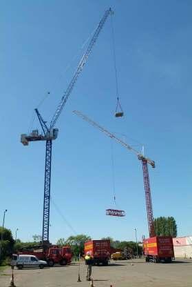

1 Training For The Future TRAINING COURSES DRIVER TRAINING CONSTRUCTION PLANT FORKLIFTS ADR / DGSA NEBOSH / IOSH CPC & MANAGEMENT COURSES Training For The Future
2 THIS TRAINING PACKAGE HAS BEEN DEVELOPED AND PRODUCED BY THE TRAINING DEVELOPMENT UNIT OF RITCHIES TRAINING CENTRE HOBDEN STREEET, SPRINGBURN GLASGOW G21 4AQ We have made every effort to ensure that the information contained within this publication is accurate. It s content should be used as guidance material only and not as a replacement of current regulations, company safety policies or existing standards DONALD RITCHIE RITCHIES TRAINING CENTRE 2
3 Further information on products / training / queries contained in this handout can be obtained from the manufactures listed below. Rud Chains Ltd Parsons Chain Company Units Worcester Road John Wilson Business Park Stourport-on-Severn Whitstable Worchestershire Kent CT5 3QT DY13 9AT Tel: Tel: Fax: Fax: Web: Web: Crosby Europe ltd Spanset Unit 10, Fall Bank Industrial Estate Telford Way Dodworth / Barnsley Middlewich South Yorkshire S75 3LS Cheshire CW10 OHX Tel: Tel: Fax: Fax: Web: thecrosbygroup.com Web: National Plant Operators Registration Scheme Ritchie s Training Centre Ltd PO Box 204, Northwich Hobden Street, Springburn Cheshire, CW9 7FY Glasgow G21 4AQ Tel: Tel: Fax: Fax: Web: Web: Ritchie s Training Centre Ltd would like to thank the company s list above for the use of their products and copyright 3
4 Health & Safety at Work Act Employers Duties Section 2(2). A B C D E Provide and maintain plant and equipment including a safe system of work. Provide safe transport and storage of materials and substances including safe handling. Provide information, instruction, training and supervision. Provide and maintain safe place of work under his control without risk to health including safe access and egress. Provide a safe working environment without risk to health, including welfare facilities. Section 2(3). Prepare a written safety policy and bring it to the attention of all employees. Section 9. Must not levy any charge for any PPE required by law. Employees Duties Section 7 & 8. 7(a) 7(b) Take reasonable care for their own safety and that of others who may be affected by their acts or omissions. Co-operate with employer to enable them to comply with their legal obligations. 8 Not to interfere with or misuse any equipment provided in the interest of health and safety. 4
5 Provision and Use of Work Equipment Regulations 1998 Interpretation (Regulation 2) The following definitions and terms are important in understanding the requirements laid down by these Regulations. Inspection This means a visual or more rigorous inspection, as required by regulation 6 carried Out by a competent person, and may include appropriate testing. Thorough examination. This means a thorough examination, as required by Regulation 32, carried out by a competent person, and may include appropriate testing. Work equipment. This includes all machinery, appliances, apparatus, tools or installations for use at work the definition will cover single machines such as guillotines right through to complete entities such as bottling plant. Use. This includes any activity that may be associated with the work equipment, such as starting, stopping, programming, setting, transporting, repairing, modifying, maintaining, servicing and cleaning. Unless otherwise stated the requirements of these Regulations are absolute, i.e. they must be achieved. Application (Regulation 3) The Regulations apply to : Work equipment provided by employers for use by their employees at work Work equipment provided by self-employed persons for their own use at work Persons who have any control of work equipment, or who use, supervise or manage its use The way work equipment is used. The Regulations do not apply to work equipment supplied by way of sale, agreement for sale, or hire purchase agreement. Various exemptions also apply to work equipment used in relation to work on or off ships. The guidance points out that the duty on employers also extends to personal work equipment provided by the employees, where the employer agrees to this practice and that on multioccupancy sites arrangements should be made for one employer to be responsible for compliance. The "co-operation and co-ordination" requirement under regulation 9 of the Management of Health and Safety at Work Regulations 1999 (MHSW) is relevant. 5
6 Information and Instructions; Training (Regulations 8 and 9) These regulations require employers to make available to all persons using work equipment adequate health and safety information, and where appropriate written instructions on the use of such equipment. In addition, the employer must also provide adequate health and safety training in the use of the work equipment, including any associated risks and necessary precautions. Adequate information and training, and written instructions where appropriate, must also be made available to persons who supervise or manage the use of work equipment. The information and instructions must be comprehensible and include: the conditions and methods of use of the equipment; foreseeable abnormal situations and any necessary actions, and any conclusions drawn from experience in the use of the equipment. With regard to training, the guidance specifically points out the importance of considering additional requirements for young and/or inexperienced persons. LIFTING EQUIPMENT: Under s.2 of the Health and Safety at Work Act 1974, employers have a duty to ensure any plant or equipment provided for use at work is safe this includes lifts and any other lifting equipment. More specific requirements are contained in the Lifting Operations and Lifting Equipment Regulations 1998 (LOLER), which remove and replace many of the previous provisions in the Factories Act 1961 and other Regulations. 6
7 The Lifting Operations and Lifting Equipment Regulations Definitions (Regulation 2). Accessory for lifting: Any work equipment used to attach loads to the lifting machinery. Lifting equipment: Work equipment used for lifting or lowering loads attachments used for anchoring, fixing or supporting the lifting equipment are included in the definition. Lifting operation: Any activity involving the lifting or lowering of a load. Load: The item being lifted or lowered and includes people. Work equipment: Any machinery, appliances, apparatus, tools or installations used at work. Application (Regulation 3) Employers have duties under these Regulations in situations where employees at work use lifting equipment. Self-employed persons have a similar duty with regard to lifting equipment they use at work. In addition, persons who have any control of lifting equipment, or who use, supervise or manage the use of lifting equipment also have a duty under the Regulations but only to the extent of their control these duties do not apply in cases where the lifting equipment has been supplied by way of sale, agreement for sale or hire purchase agreement. Strength and Stability (Regulation 4) Lifting equipment must be of adequate strength and stability for each individual load raised or lowered and particular attention must be paid to the stresses incurred at the mounting or fixing points. Load parts and any attachments used in the lifting operation must also be of adequate strength. Lifting Equipment for Lifting Persons (Regulation 5) Lifting equipment used for lifting people must prevent anyone using it from being crushed, trapped or struck, or from falling from the carrier. Similar precautions are required for work activities being carried out from the carrier, as far as reasonably practicable. There must also be suitable devices to prevent the risk of a carrier from falling. If this risk cannot be prevented the carrier must have an enhanced safety coefficient suspension rope or chain which must be inspected on each working day. People trapped inside a carrier must be protected from danger and be able to be freed. 7
8 Positioning and Installation (Regulation 6) Lifting equipment must be positioned and installed so as to be safe, and minimise the risks, as far as reasonably practicable, of the lifting equipment or its load striking a person, or its load drifting, falling freely or being unintentionally released. Suitable devices must be provided to prevent people from falling down lift shafts or hoist ways. Marking of Lifting Equipment (Regulation 7) Lifting equipment must be clearly marked with its safe working loads. In situations where the safe working load is reliant on the equipment configuration, the safe working load for each configuration must be clearly marked on the lifting equipment. Alternatively, information containing these details must be kept with the lifting equipment. Accessories used in lifting operations must be marked with any information necessary to ensure their safe use. Lifting equipment intended for lifting people must be clearly marked as such. Any lifting equipment not intended for lifting people but which may be mistakenly used as such must also be clearly marked to this effect. Organisation of Lifting Operations (Regulation 8) Lifting operations involving lifting equipment must be properly planned by a competent person, appropriately supervised and carried out in a safe way. Thorough Examination and Inspection (Regulation 9) Lifting equipment must be thoroughly examined for defects before it is put into service for the first time. This does not apply in situations where the lifting equipment has not been used before and there is an accompanying EC declaration of conformity (where this is appropriate) which is less than 12 months old before the lifting equipment was put into service. Lifting equipment obtained from a third party must be accompanied by physical evidence of the last thorough examination before it is used in the new employer's premises. Lifting equipment must also be thoroughly examined to ensure correct installation and safe operation after it has been installed and before being put into service for the first time, or after it has been relocated, if its safety is dependent on its installation. Where lifting equipment is exposed to conditions that may cause deterioration likely to result in danger it must be thoroughly examined as follows: Lifting accessories and lifting equipment for lifting persons: at least every 6 months Other lifting equipment: at least every 12 months. In both cases a competent person must draw up an examination scheme, i.e. a suitable scheme that determines the frequency of the thorough examinations. Lifting equipment must also undergo a thorough examination if exceptional circumstances have occurred that may adversely affect the safety of the lifting equipment. 8
9 A competent person may inspect lifting equipment at suitable intervals between thorough examinations if necessary. Lifting equipment, which was required to be thoroughly examined under specified legislation that has been repealed or revoked by these Regulations, must undergo another thorough examination before the date on which the previous thorough examination is due for renewal. Reports and Defects (Regulation 10 and Schedule 1) The person undertaking the thorough examination must notify the employer immediately of any defects that are, or could be, a danger to people, and as soon as practicable submit a written and signed report to the employer and, if appropriate, the person hiring or leasing the lifting equipment. The enforcing authority must also receive a copy of any report where there is an existing or imminent risk of serious personal injury due to a defect in the lifting equipment. For lifting equipment that has been hired or leased the enforcing authority is the Health and Safety Executive (HSE), in other cases it is the enforcing authority for the premises. The information required to be included in a thorough examination report is as follows: 1. Name and address of employer. 2. Address of premises at which the thorough examination was made. 3. Lifting equipment identity marks, including date of manufacture if known. 4. Date of last thorough examination. 5. Safe working loads, including those associated with equipment configurations. 6. Where the thorough examination relates to the installation or assembly of the lifting equipment, notification of that fact and that it has been installed correctly and is safe to operate. 7. Information as to whether the thorough examination relates to a 6 or 12 monthly examination carried out under an examination scheme, or an examination carried out in cases of exceptional circumstances where the safety of the lifting equipment may have been jeopardised. The report should also state that the lifting equipment is safe to operate. 8. Details and identification of any parts found to be defective, including a description of the defect, where the defect is or could become a danger to people. 9. Details of any necessary repairs, renewals or alterations to correct a defect. 10. In cases where the defect may represent a danger to people the following must be included: The time in which the defect could become a danger Details of repairs, renewals or alterations necessary to correct the defect The latest day on which the next thorough examination must be carried out Details of any tests if these are included in the thorough examination The date. 11. Name, address, qualifications and employment status of the person making the Report if the person is an employee then the name and address of his or her employer must be included. 12. Name and address of the person signing or authenticating the report. 13. Report date. Defects noted during an inspection of the lifting equipment, which pose or may pose a danger to people, must also be notified to the employer immediately. A written record of the inspection must be made. Employers may not use any lifting equipment notified as having a defect before the defect is corrected. In cases where the defect could become a danger, the lifting equipment may not be used after the time specified in the report (i.e. the time after which the defect is deemed by the competent person to be dangerous) until the defect is corrected. 9
10 Keeping of Information (Regulation 11) Employers must retain EC declarations of conformity that relate to lifting equipment obtained after 5 December 1998 for as long as they operate the lifting equipment. Thorough examination reports for lifting equipment must be retained until the lifting equipment ceases to be used, while the thorough examination reports for lifting equipment accessories must be kept for two years. Thorough examination reports relating to the installation or assembly of lifting equipment must be kept until the equipment ceases to be used at the location where it was installed or assembled. Finally, thorough examination reports that relate to the deterioration in condition of lifting equipment must be kept either until the next report is made, or for two years, whichever is the later. Records relating to the inspection of lifting equipment must be kept until the next record is made. PERSONAL PROTECTIVE EQUIPMENT: The Personal Protective Equipment at Work Regulations 1992 (PPE Regulations) came into force on 1 January 1993, and were introduced under the provisions of the Health and Safety at Work Act 1974 (HSW Act) to enable Great Britain to implement the requirements of European Directive 89/656/EEC. The Directive obliges Member States to introduce minimum health and safety requirements for the use by workers of personal protective equipment (PPE) at the workplace. The following regulations are part of the Personal Protective Equipment at Work Regulations Interpretation (Regulation 2) PPE means all equipment and clothing which is intended to be worn or held by a person at work and which affords protection against one or more risks to health or safety. This includes clothing designed to protect against adverse weather conditions. Protective clothing includes, for example: aprons, gloves, safety footwear, safety helmets and high visibility jackets. Protective equipment includes, for example: eye protectors, safety harnesses, respirators and life jackets. Disapplication (Regulation 3) Ordinary working clothes and work uniforms that do not offer specific protection are not covered. Therefore caterer's overalls and similar clothing provided solely in the interests of food hygiene do not constitute PPE, whilst a re-enforced glove provided to a chef to safeguard against injury would count as PPE. Modifications, Repeals and Revocations (Regulation 14) Much of the older legislation on PPE has been revoked, notably the Protection of Eyes Regulations
11 Provision and Compatibility (Regulations 4 and 5) Except where risks are adequately controlled by other means, employers must provide suitable PPE to employees who may be exposed to those risks (regulation 4). The self-employed must make provision to themselves in respect of their own activities. There is no duty under these Regulations to supply PPE to non-employees such as visitors or voluntary workers. However, s.3 of HSW Act imposes a duty of care towards non-employees and this may indicate a need for the supply of PPE. Persons gaining work experience are entitled to the same provision for PPE as if they were employees, by virtue Of the Health and Safety (Training for Employment) Regulations The employer should consider PPE as a last resort, or as an interim solution to a risk of exposure pending control by engineering or other means. The reasons are: PPE only protects the person wearing it and not others in the vicinity; wearing PPE may give a false sense of security as it is seldom fully effective and PPE can be cumbersome which may give rise to other risks or adversely affect performance. Examples of processes that may require the provision of PPE, subject to an assessment by the employer include the following. 1. Head protection: Construction and building, particularly in the vicinity of scaffolding Underground work including working in pits, trenches and tunnels Ship repair Tree felling Work near hoists, lifting plant and cranes. 2. Eye protection: Handling chemical substances such as acids, alkalis and other corrosive or irritant substances Working with molten metals Working with abrasive wheels or any machine likely to eject particles During welding operations where intense light may otherwise cause damage to the eye. 3. Hand protection: Handling chemical substances where there is a risk of dermatitis or of damage to skin tissue During construction and outdoor work Where there is a risk of cuts or abrasions Where articles may be hot, cold or slippery Where there is a risk of electrical shock When using vibratory tools. 11
12 4. Foot protection: Where there is a risk from molten metal splashes To prevent injury from falling objects Where special slip-resistance is required In flammable atmospheres, where the build-up of static electrical charges creates a risk of explosion Where there is a risk of sharp objects piercing the sole, such as in the use of nails on a construction site. 5. Body protection: Warm clothing when working outdoors in low temperatures, or in cold-stores Protection against intense heat and/or flame retardant clothing when working at a foundry, or with welding equipment High visibility clothing when working in the vicinity of moving traffic, airports, etc Cut-resistant clothing when using chain saws or butcher's knives Life jackets when working near deep water. Employers must take all reasonable steps to ensure that PPE is properly used. This includes giving proper and adequate information, instruction, training and supervision, and the use of disciplinary procedures where appropriate. Where there is a statutory requirement for PPE to be used, this should be indicated by use of safety signs to BS These are in the form of a blue circle upon a white background (see SAFETY SIGNS). CHARGES Section 9 of the Health and Safety at Work Act 1974 states: No employer shall levy or permit to be levied on any employee of his any charge in respect of anything done or provided in pursuance of any specific requirements of the relevant statutory provisions. To be suitable, PPE must: Suitability (a) Be appropriate for the risk(s) involved and the conditions at the place where exposure may arise (b) Take ergonomic considerations into account, and be capable of being fitted to, and used by, the worker (c) So far as is practicable, prevent or adequately control the risk of exposure without creating overall risk (d) Be designed and manufactured to an approved standard. Where more than one sort of PPE has to be used simultaneously, each must be compatible with the other and full effectiveness must be maintained (regulation 5) 12
13 Assessment (Regulation 6) Prior to selecting PPE, the employer or self-employed person must ensure that an assessment has been made to ascertain whether the proposed PPE is suitable (regulation 6). A risk assessment made under this regulation need not be duplicated in order to meet the requirement for assessment under regulation 3 of the Management of Health and Safety at Work Regulations 1999 (MHSW) although it should be easily identifiable and well crossreferenced. Except in the most simple and obvious of cases, or where the exercise can be quickly and easily repeated, the significant findings of an assessment should be recorded in retrievable form. The record should be readily accessible to those who may need to know the results. Employees should be involved in the selection of types and styles of PPE, and should have an informed choice wherever possible. Selection should be made with the individual in mind what is suitable for one person may be useless for another. For example, a worker who requires spectacles with prescription lenses will be unable to work whilst wearing non-prescription eye shields. In selecting PPE, the employer or self-employed person must consider: Risks to health or safety that have not been avoided by other methods The sort of performance and characteristics that the PPE would need to have, for it to be effective Comparison of the proposed PPE with the required performance and characteristics. The assessment must be reviewed where there is reason to suspect that it is no longer valid. Maintenance and Storage (Regulations 7 and 8) PPE must be maintained (e.g. cleaned, repaired or replaced) in an efficient state (regulation 7). A stock of spare PPE, spare parts and cleaning materials should be kept to facilitate this. Suitable storage should be available to prevent damage to PPE, including that which has been issued to users. PPE that has been supplied free of charge by an employer for use at work remains the property of that employer. It is in order for the employer to instruct that it is kept at the workplace and is not used for non-occupational purposes. Information, Instruction and Training (Regulation 9) Under this regulation employees must be given adequate and comprehensible instructions, information and training in: The purpose for which PPE has been provided The risks that it will protect against The correct method of use The employee's part in ensuring that PPE remains in an efficient state, properly working and in good repair. 13

14 Employee's Duties (Regulations 10 and 11) Employees are obliged to use PPE in accordance with the instructions and training that they have been given (regulation 10). Employees and the self-employed must also take all reasonable steps to return PPE to designated storage or accommodation after use. Sections 7 and 8 of the HSW Act lay down general duties for employees. The MHSW Regulations 1999 further require each employee to properly use any equipment, system of work or other measure provided by the employer in accordance with the instruction and advice that has been given. This general duty extends to the proper use of PPE. Where an item of PPE becomes defective or is lost, the employee must report the loss or defect immediately to the employer (regulation 11). CONCENTRATION OBSERVATION MACHINE CONDITION - VISUAL CHECKS, DAILY INSPECTION MACHINE KNOWLEDGE MECHANICS, CAPABILITIES, CONTROLS ONLY ACT ON YOUR OWN JUGEMENT NEVER TAKE A CHANCE ALWAYS TAKE CARE SELECT CORRECT SLINGS LIFTING EQUIPMENT EXPERIENCE OF SIMILAR LIFTS LIFTING EQUIPMENT NEVER BE HURRIED KEEP WITHIN YOUR OWN LIMITATIONS S.L.I. CORRECT FOR JIB LENGTH & CRANE/RADIOUS PLATE EXERCISE YOUR RIGHT TO QUESTION ANY LIFT REMEMBER You are the person in charge of the lift, and the lives of your workmates depend upon your ability BETTER TO BE SAFE THAN SORRY 14
15 The Basic duties of a slinger: To prepare the load for lifting. To prepare the sling and connect it to the load and crane To steady the load whilst lifting and moving it from one position to another. To be fully responsible for the safe transfer of the load from one position to another. To be solely responsible for giving the orders to the crane operator. To be conversant with the standard crane signals and to use them at all times. To examine the lifting gear before and after use as required by the LOLER Regs. Rules for safe slinging. It is difficult to lay down rules that will cover all slinging methods, as these must vary according to circumstances, but certain general rules and precautions should be followed to ensure safe working practices. The following points are designed to assist the slinger in the safe handling and transfer of loads: Know the weight of the load to be lifted and ensure that it does not exceed the Safe Working Load (SWL) of the tackle and crane. Use only authorised tackle, which is marked with the SWL. Unmarked tackle should be reported to the Supervisor. Inspect ALL tackle before use. Report damaged tackle and have it destroyed. Remember that with 3 or 4-legged slings, 2 legs may take all the weight. When reeving slings around a load the angle at the bight must not exceed 120 degrees. NEVER tie knots in slings or shorten by wrapping them around crane hooks or by using a nut and bolt. ALWAYS use the correct pins in shackles and fasten them securely. NEVER use rusty wire ropes, or fibre ropes, which have been in contact with acids or alkalis. Rings and shackles must ride freely on the crane hook. NEVER lift with the point of the hook. NEVER put sharp bends in wire ropes. Always protect slings from sharp corners by using packing. 15
16 NEVER drag slings along the floor. Keep wire rope slings away from welding and flame cutting operations. Use chain slings when lifting hot metal. Check that all parts of the load are safely slung. Keep hands away before lifting and stand clear while the load is being lowered. NEVER stand under a suspended load. NEVER allow a load to pass over people s heads. DO NOT trap slings under a load. Use dunnage to give clearance for sling removal. Use only the correct signals and make sure that they are clearly understood by the crane operator. NEVER store lifting tackle in your own locker. It must be freely available for regular inspection. NEVER store lifting tackle on the floor. NEVER attempt to raise or lower a load unless it is completely free from all obstructions. Never hammer a chain to straighten a link, or to force a link into position. Always SPOT the load and lift vertically to prevent swinging. Use steadying lines (tag lines) to gain complete control. Always make sure you are in a position where the crane operator can see you. When working with uneven loads, always find the centre of gravity by trial and error without actually lifting the load clear of the ground. When using multi-leg sling assemblies, remember that the angles between the legs will reduce the safe working load of the assembly. Consult the Sling Chart and Safe Load Tables available. Endless wire rope slings are prone to misuse. And in practice they are often found to be difficult to handle. It is preferable that they are used only when they have been purpose made for applications requiring a very short effective length, or for single lifts where a single sling of the required Safe Working Load is not available. Do not use any sling that contains a severe kink. When loads are being carried on a crane hook, slings not in use should not be carried on the same hook. A sling, which has been doubled around a shackle, has a Safe Working Load equivalent to that of a single part of the rope. 16
17 Check that the crane hook is positioned over the load s centre of gravity to prevent swinging when the load is raised. Make sure that the load is free before lifting, and that all legs have a direct lead. When not in use, wire rope slings should be kept in a dry store, to prevent corrosiontaking place. FACTS Lifting equipment is involved in more serious accidents than any other type of construction equipment. Accidents involving lifting equipment are more costly in terms of insurance. Cranes and lifting equipment and the use of are one of the major causes of construction site fatalities. Cranes Before commencing a lift with a crane it may be required for the banksman to assist with the on site planning and positioning of the crane and associated equipment. Check the work site with the supervisor and the crane operator and assess the crane suitability for the whole job. Assess access, room, soil, lift capacity and lifting equipment. Decide where to set up and how to set up This is part of: Site and job planning Before commencing lifting operations the crane driver and banksman must ensure that proper site planning has taken place. The procedure to be followed in preparing an operational plan for lifting includes: Job requirements Priorities of the job Workplace rules and procedures Identifying hazards Hazard control measures Persons to consult with when planning the proposed work: Building owners Statutory authorities where necessary Local councils Site manager and supervisor Other trades working on site 17
18 This will ensure that the crane driver and banksman are aware of, comply with, any statutory or workplace rules, regulations or restrictions that may apply. This is required under the DUTY of CARE of every person at that work site. Types of hazards to be considered for you work plan. Unstable ground surface, i.e. recently back filled excavations Other personnel working on the area Under ground services (Proximity hazards) Dangerous materials Power lines overhead or underground Trees Surrounding structures Bridges, access restrictions Other work equipment on site Hazard control strategies to be included in the plan for lifting procedures; must include The task being preformed Any site hazards trenches and filled ground, power lines, obstructions in the working radius of the crane, trees, scaffolding, access and exit points PPE required when working with hazardous or non-hazardous materials Warning signs displayed properly Barriers and barricades to restrict access Traffic control Lighting Public safety Ground conditions If the ground on which you require to set the crane up on is waterlogged or soft, Appropriate steps must be taken prior to the crane setting up to assess the soil and ground condition. This may well be required to be completed by a competent person (civil engineer or equivalent) Excavations A crane should not be set up close to an excavation as the weight of the crane causes Additional pressure to adjoining soil and cause the excavation to collapse and result in The crane overturning. As a general rule the distance of the cranes outrigger pad from The edge of the excavation should be at least the same as the depth of the excavation +1 metre Free on wheel duties (lifting and carrying a load) If you are in doubt concerning the safety of a free duty lift stop and consult with the competent person in charge of the operation. Some cranes are better suited than others to travel over rough surfaces. Always check the cranes load chart and manufacturer s recommendations before carrying out any lift that requires Free on wheels duties. 18
19 Cranes are more likely to overturn off road. Before carry out a free on wheels lift check: For potholes and soft or rough ground For overhead obstructions For power lines For personnel working in the area Blind corners Traffic flow Underground services Always check grassy surfaces for potholes or drains hidden by long grass. Walk over the whole area before guiding a crane across Make sure cranes suspension units are locked and pinned Do not direct the driver to slew unless the surface is firm and level Do not walk heavy loads with crawler cranes unless the ground is firm and level Travel slowly to prevent excessive swings TANDEM LIFTS Your company should have an restriction on tandem lifts The only tandem lifting should be engineered through the office The dangers in tandem lifts are the cranes are going to side load each other It s impossible to swing a load without side loading one of the cranes Crane jibs must be kept parallel Tandem lifts are dangerous They can be done safely if they are planned and every one involved are properly trained If you get in trouble CAN WE GET OUT OF IT? IF IN ANY DOUBT GET HELP FROM YOUR OFFICE OR SUPERVISOR CRANES MUST BE SET UP AS PER CRANE DUTY CHART, RISK ASSESSMENT & METHOD STATEMENT 19
20 Multiple Crane Lifting INTRODUCTION: The use of two or more cranes to move and position loads can be very hazardous and should not be considered where a single crane is capable of doing the job. There are, however, occasions when multiple crane lifts are necessary. They are often required during the construction and assembly of oil and gas rigs and in the construction of bridges and large-scale industrial projects such as power stations and refineries. CERTIFICATION: The appointed person / competent person with direct responsibility for coordinating and directing a multiple crane lift must hold a Banksman / slinger or a rigging certificate PLANNING AND COORDINATING: For very complex lifts, the advice of an experienced structural engineer may be required to properly plan the operation, but the certified rigger must maintain immediate supervision at all stages The importance of careful planning and the need for a thorough briefing of all personnel involved in the lift cannot be overstated. Many multiple crane lifts have come to grief through oversights, wrong selection of cranes, incorrect siting of cranes and misunderstandings between crewmembers. If the weight of the load, it s centre of gravity and the weight of the lifting gear is not known in advance, they must be carefully calculated. Whenever possible, a dummy run should be staged prior to the lift to check that the cranes can perform all stages of the operation within radius while maintaining sufficient clearance from obstructions and power-lines. This exercise should also be used to confirm that the agreed communication method is under stood and is suitable. CRANE SELECTION AND SITING: Whenever possible, select cranes of equal capacity and similar Characteristics. This will make synchronisation of crane movements easier to achieve. Each crane must have additional capacity over and above its share of the load at all times during the operation. This is to allow for the possibility of the hoist ropes deviating from vertical or other loads transferred through imperfect synchronisation of crane movements. The minimum capacity requirements for each crane are: When 2 cranes are used 20% greater than the share of the load When 3 cranes are used 33% greater than the share of the load When 4 cranes are used 50% greater than the share of the load 20

21 Crane siting must be carefully considered so that movements are reduced to the minimum necessary. The crane siting can be limited by the nature of the work site, the position of obstructions and power-lines, or the existing position of tower cranes Wherever possible, site the cranes to avoid slewing motions. Always use luffing-up in preference to luffing-down. Luffing-down is dangerous because it can easily lead to the load swinging one or more of the cranes outside the safe operating radius. Wind loading adds to the dangers of luffing down. Where the cranes are required to pick and carry, they must be aligned in the same direction. If they are out of alignment, the movement of one crane can push or pull the other cranes and stability may be lost. CALCULATING LOAD-SHARE Where the load to be lifted is beyond the capacity of any of the selected cranes, equalising gear may be required to ensure that each crane supports its correct portion of the load. Equalising gear needed when the cranes are close together, such as for lifting large columns and similar objects. It also acts as a lever. When cranes are of a differing capacity, the load to be lifted should be slung away from the centre of the equalising beam so that the load taken by each is proportional to its capacity. The load is slung closer to the end of the equalising beam supported by the larger capacity crane, to increase its share of the load and reduce the part of the load carried by the second crane. WARNING: NOTE: Tower cranes are prohibited from carrying out any form of tandem lifts Always check own company safe system of work or method statement. SLINGS SELECTION & INSPECTION. A sling is as important to a banksman / crane operator as is his crane. The correct type of sling used in lifting is very important to both the operator and the load that is being lifted. The correct sling should always be used and should be inspected before and after use. INSPECTION OF TACKLE. All lifting tackle by law has to be inspected every 6 months or as per company safety policy. Companies must have a log of all tackle to include inspection dates. Example: - Steel Wire Ropes chains slings hooks shackles - eye bolts etc. 21
22 Eyebolts Eyebolts are used for lifting loads, which are usually heavy and concentrated. They are used for general lifting and for permanent attachment to loads, which are to be moved occasionally. They are screwed into tapped location holes provided, and usually will not accept a hook, but must be used with a shackle. Dynamo Eyebolt This has a large eye and a small collar diameter. Normally fitted By the manufacture to the item to which they are attached, they Need not be marked with a S.W.L, are not registered, and are not Examined six monthly. This type of eyebolt should only be used for Vertical lifts. Collar Eyebolt This has a smaller eye, a larger collar diameter and the thread is Undercut on both the diameter and the collar face. They should Be marked with a S.W.L, registered as a piece of lifting tackle, And examined six monthly. This type may be used, in pairs, for Taking an angular pull, but the angle of pull must be in line with the plane of the eyebolt. Shims may be needed to allow This. The maximum washer thickness should not exceed half the Pitch of the thread. Eyebolt with link This type has a link permanently attached to the eye and should be Marked, registered and examined. They may be used for taking an angular pull, but unlike collar eyebolts, The angular pull need not be in line with the plane of the eyebolt, this Renders the fitting of washers or shims unnecessary. NOTE The S.W.L marked on any eyebolt is only applicable to a vertical Lift. Whenever an angular pull is used, the rated S.W.L decreases as the Angle of pull from the vertical increase. 22

23 Eyebolts Collar & Dynamo Eyebolt threads include Whitworth, BSF, UNC, UNF, or Metric Extreme care must be taken to ensure that metric threaded eyebolts are not inserted in imperial threaded holes. Although these might appear to match, it is an interference fit only. The mechanical strength may be almost nothing. Eyebolt Type / Selection Is the load applied Vertically only YES Use Dynamo Eyebolt NO Is load in plane of eye YES Use collar Eyebolt NO Use Eyebolt With link 23
24 Eyebolts Collar & Dynamo Dynamo or plain eyebolt Collar eyebolt Eyebolts are made to screw into or through a load and may be Plain (Dynamo) or have collars (collar eyebolt) The plain eyebolt is good only for vertical loading. Even when a collard eyebolt is used, the safe working load is reduced with angular loading When installed, the collar must be at right angles to the hole and Must be in full contact with the surface of the load and be properly Tightened. The load should always be applied to the plain of the eye and never in The other direction. If necessary, Shims should be inserted Below the collar to ensure that the eye is correctly aligned when tight. Collared eyebolts with links may be used providing angle Of The load to axis of eyebolt thread does not exceed 15 Over 15 safe working loads must be de-rated in Accordance with BS (See weight reduction chart below) 24
25 Eyebolts Maximum shim thickness not to exceed ½ the pitch of the thread Maximum angle allowed out of plain is 5 No more than ½ turn to align to correct plain of eye Hand tight only do not over tighten I.S.O METRIC COURSE THREAD (ALL DIMENSIONS IN mm. s) Diameter Pitch NOTE: ALL PITCH SIZES MUST BE HALVED TO GIVE CORRECT SHIM THICKNESS
26 Collar Eyebolts Maximum angle allowed 1T 90 2T 1T 90 REDUCE BY 75% 60 REDUCE BY 60% 30 REDUCE BY 40% Eyebolts with links maximum angle of 15 from vertical when over 15 reduce with table above 26

27 Collar & Dynamo Eyebolts Trunnion Lifting Eyebolts screwed into the side of the load must be de-rated by 75% on each eyebolt 27
28 Weight Reduction Chart Eyebolts 30-40% 60-60% 90-75% The flatter angle of pull, the greater the strain and leverage on the eyebolt Maximum angle allowed on slings when working with eyebolts is 45 from vertical (Included angle of 90 ) 28

29 Collar Eyebolts Reeving through connections to load increases load on Connection fitting by as much as twice DO NOT REEVE 29
30 SAFE WORKING LOAD TABLE FOR COLLARED LIFTING EYEBOLTS METRIC NORMAL SIZE SINGLE EYEBOLT SWL PER PAIR OF EYEBOLTS TRUNNION AXIAL MOUNTING PERPENDICULAR DEGREES DEGREES 90 DEGREES tonnes tonnes tonnes tonnes tonnes tonnes M10 3/ M12 ½ M16 5/ M20 ¾ M22 7/ M M M33 1 ¼ M ½ M42 1 ¾ M M M64 2 ½ M M The above table is derived from AS and BS or manufacturers specifications for the Safe Working Load of collared eyebolts when used in the correct manner as described in " Care and use of eyebolts". The loads indicated are for "General Purpose Use" 30


31 RUD Star Point Swivel Eyebolt Self aligns to direction of force Higher WLL capacity than standard eyebolts Load rated for side pull Rotates 360 degrees Integrated key for quick and easy installation and removal Compact design Rotates to direction of pull Fold down flat Ideal for side pull application Grade 80 belts are interchangeable for through hole application Holding springs reduce vibration WLL from 660 lbs. to 44,000 lbs. Metric and UNC threads WLL from 17,600 lbs. to 33,000 lbs. in any direction o Ball bearing swivel rotates 360 degrees o Larger ring for hook and shackle attachment o Clearly marked WLLs o Tested and certified - certificates available Great Britain 31


32 RUD Star Point Swivel Eyebolt Chart Rud Chains Ltd. John Wilson Business Park Units Thanet Way Whitstable, Kent CT5 3QT Phone: Fax:


33 Crosby Swivel Hoist Ring Red UNC thread Rated at 100% at Swivel and 180 Pivot Action No need for washers or shims Silver Metric thread Used with chains slings Used with webbing slings 33
34 Eyebolts Reasons for use Lifting heavy concentrated loads Electric motors / Machinery Pre cast concrete IE. Floors / Stairs Eyebolts Weaknesses & Reasons for Failure Eyebolts have severe limitations of use Corrosive damage / non use of shims Eyebolts not screwed home properly Using wrong eyebolts / Incorrect thread size Using eyebolts in acidic environments Lifting loads out of plain & Using bent or damaged eyebolts Eyebolts Care and maintenance Do not store in-situ return to tackle store Protect threads from damage Slightly oil or grease to prevent corrosion Clean threads of debris with wire brush 34
35 Lifting & Spreader Beams General Information Spreader beams are used to support long or wide loads during lifts They eliminate the hazard of load tipping, as well as wide sling angles and any tendency of the sling to crush the load Equaliser beams are used to equalise the load in the sling legs and to keep equal loads when making multiple leg lifts Care must be taken not to exceed the S.W.L at the various slinging points Spreader Beam Equaliser Beam Multiple attachments The capacity of a beam with multiple attachments will be specified by markers. Generally it depends on the distance between the parts, if the distance between attachment points is doubled the capacity is halved 35
36 Lifting / Spreader Beams Reasons for use Areas of Low headroom Avoids wide sling angles that would crush a load Lifting unbalanced loads Tandem lifts on loads Spreader Beams Weaknesses & Reasons for Failure Unstable with loads with a low centre of gravity Corrosive damage Damage to bolted or welded areas / attachments Lifting loads outside design spec Overloading attachment points Spreader Beams Care and maintenance Store beams in dry conditions Store beams on stands or adequate packing If beams are dismantled store all parts together & Reassemble correct components 36


37 Shackles Bow shackles should be used when one or more attachment is made, or to allow movement on the plain of the shackle Dee shackles are usually joining shackles Only use shackles that are marked with their safe working load Never use bolts instead of Proper shackle pins 37
38 Shackles In line 100% of rated capacity 45 from in line 70% of rated capacity 90 from in line 50% of rated capacity Shackles symmetrically loaded with two leg slings having a maximum included angle of 120 can be utilized to full working load This applies to Crosby shackles only unless stated by your supplier 38

39 Crosby Shackles Point loading of Crosby shackle bow is acceptable Point loading of Crosby shackle pins is acceptable as long as load is reasonably centred on the pin Although point loading is acceptable a pad eye width of 80% or more of shackle spread is best practice. This applies to Crosby shackles only unless stated by your supplier 39


40 Safe Use Of Shackles Shackles should be fitted in a manner that allows the shackle body to take the load in a true line along its centre line. Correct Incorrect Correct Shackle pin cannot turn Incorrect Shackle pin can work loose Incorrect Correct 40


41 Crosby Shackles & Fittings Working Range shackles) Link plate (Joining Web sling saver Spool Wide body sling saver Crosby Europe ltd Unit 10, Fall Bank Industrial Estate Dodworth / Barnsley South Yorkshire S75 3LS Telephone WEB: thecrosbygroup.com 41
42 Shackles Reasons for use Shackles are used in the main for attaching Lifting gear to the crane hook Lifting gear to the load Bow shackles for more than one attachment Dee shackles for joining Shackles Weaknesses & Reasons for Failure Shackles have no apparent weaknesses under normal use as long as they are looked after properly The main reason for failure is overloading, eccentric loads and misuse Check for distortion and damage to the pin Check that it is the correct pin for the shackle That the pin is seated correctly Shackles Care and maintenance Maintenance of shackles are minimal Keep clean protect from corrosion and ensure that threads are protected from damage 42


43 Webbing Slings There are usually lines of black stitching on webbing slings the amount of lines denotes SWL i.e. two lines of stitching = 2 tonne SWL I.D. tag Webbing slings are issued with a statement of conformity confirming the safe working load Due to the materials used in webbing slings they would be unsuitable for proof testing 43


 Nylon: When Wet")

44 Webbing Slings Various attachments available for webbing slings Blue label: 100% Polyester Nylon: Resists Weak Alkalis Polyester: Resists Weak Acids Polypropylene: Resists Both (but will stretch easy) Nylon: When Wet Must Reduce SWL by 50% NOTE: No natural fibre slings will be used on a construction site 44


45 Damage to Webbing Slings Any damage to webbing slings disregard Feel Internal strands in slings For damage Damage or cuts to sleeve Protect from sharp edges of load Do not tow or drag any loads Keep away from Acids or Alkalis Keep away from frost or extreme cold Keep away from heat Keep away from any U.V. Light Keep away from mildew Always store in dry clean place 45
46 Webbing Slings Resistance Chemical Resistance Chart Chemical Polyester Acid * Alcohols Aldehydes Strong Aldalis ** Bleaching Agents Dry cleaning Solvents Ethers Halogenated Hydrocarbons Hydrocarbons Ketones Oils, Crude Oils, Lubricating Soap and Detergents Water and Seawater Weak Alkalis OK NO OK OK NO OK OK OK OK OK OK OK OK THIS IS A GENERAL GUIDELINE ONLY *Disintegrated by concentrated sulphuric acid. **Degraded by strong alkalis at elevated temperatures. Spanset Webbing Sling Chart 46
47 Webbing Slings Reasons for use Light in weight for given capacity Easier to handle than Wire or Chain Can be pushed thought narrow gaps Unaffected by Grease or Rust Webbing Slings Weaknesses & Reasons for Failure Durability and storage deterioration is poor Prone to abrasion damage Can be contaminated by alkalis and acids Affected by heat Web slings are inclined to stretch and may not be suitable for precise positioning Webbing Slings Care and maintenance Webbing slings char or decompose over a range of temperatures, NEVER! Dry slings near a fire or heating pipes, as overheating will cause embrittlement Can be cut by loads if unprotected 47

48 Wire Rope Slings Wire rope slings are available in a wide range of capacities and sizes Danger do not use if Any wires broken at collar area or Stretch or damage to thimble Pressed metal sleeve Soft eye It is crucial that the SWL stamped upon The sling is adhered to 48

49 Wire Rope WIRE ROPES: Note: Types of lay: Type identified by a number 6/7, 6/12, 6/24 the first figure Refers to the number of strands to the rope and the second Figure to the number of wires in the strands. Wire ropes may be fibre cores or steel cores. Fibre cores Are more flexible steel core are stronger. Steel cored rope must be used in hot works condition only The two most common types of lay are: - LANGS LAY: Where the wires in the strands are twisted In the same direction as the strand in the rope (Running Rope) ORDINARY LAY: Where the wires in the strand are twisted in the opposite direction to the strands in the rope. (Pendant Rope) Safety Factor Mobile Crane Hoist Rope to 1 Overhead Crane (Gen. Duties) 6 to 1 Wire Rope Slings 6 to 1 Multi Leg Slings 8 to 1 Lifts and Hoists (Goods) 6 to 1 Lifts and Hoists (Passenger) 12 to 1 The Regulations State: - A wire rope shall not be used when more than 5% Or one in twenty of the wires, can be seen to be damaged In any ten diameter length. 49

50 Wire Rope Chart Rope dia. (mm) 1 Leg Tonnes Endless Tonnes 2 Leg Tonnes 3&4 Leg Tonnes
51 Wire rope Slings Reasons for use Lighter than chain for given capacity Can be applied where no lifting points are on the load Can be hooked into lifting points i.e. Lugs, Shackles Flexible Wire rope Slings Weaknesses & Reasons for Failure Wire rope Slings may be Damaged when Kinked sharply Or put under Stress when Twisted Never use if more than 5% of the wires, can be seen to be broken in any 10 Diameter lengths Wire rope Slings Care and maintenance Steel wire may be damaged by corrosion through poor care and storage As with all lifting gear do not leave ropes laying around on floor 51


52 Chain Slings Master link Capacity of sling Identification No. Maximum sling angle Chain Reach Auxiliary Link C hook Safety catch Regularly examine Chains for Stretch are both chains of equal length Legible markings Worn, Stretched or twisted links Cuts, Nicks, Gouges, Cracks, Corrosion Heat discoloration Or any other defect apparent to the fittings Maximum wear on a link 10% 52


53 Chain Sling Shorting Clutches Stress on link Dead end Wrong Correct Load bearing legs must go through bottom of clutch Chains should be kept the same length Dead ends of chain must be kept together Remember the shorter the chain slings are the wider sling angle, therefore causing more stress Working Angle 53


54 Chain Sling Sling Angles Maximum sling angle 90 Chains can be used up to a 120 angle if tested for such a use Avoid sling angles less than 15 this could cause load instability Do not use multi leg slings at angles within the shaded area When slings are used in choke hitch the working load limit should be reduced by 20% Sling Temperature Reduction in Working Load Limit Grade 8 Grade C to 200 C None None 200 C to 10% 300 C Do Not Use 300 C to 25% 400 C Above 400 C Do Not Use 54
55 Grades of Chain Slings * Not to be used for lifting purposes * Wrought Iron: Very little mechanical strength unless heat-treated periodically. * Mild Steel Grade 30: Low carbon content producing a soft chain with high ductility. High Tensile Steel Grade 40: Medium carbon steel has good wear and shock absorbing properties also used for shackles, eyebolts & other lifting gear Alloy Steel Grade 60: Alloy steel of this grade produces a chain 50% stronger than high tensile steel and does not suffer from brittleness in extreme cold Alloy Steel Grade 80: Harder than lower grades and more resistant to wear, allowing for a lighter sling for given load. Alloy Steel Grade 100 (8 + 10): 25% better lifting properties than a grade 80 chain sling Grade S.W.L Proof Breaking Factor of Load Load Safety * Wrought 6 tons 12 tons 27 tons 4.5 to 1 * Mild steel (G30) 6 tons 12 tons 30 tons 5 to 1 High tensile (G40) 8 tons 16 tons 40 tons 5 to 1 Alloy steel (G60) 12 tons 24 tons 60 tons 5 to 1 Alloy steel (G80) 20 tons 40 tons 80 tons 4 to 1 Due to risk of embrittlement alloy steel grade (t) chain slings must not be used in acid or acid laden atmospheres. 55
56 56
57 Load vs Sling Angles 5.0t 5.0t Straight lift: Each leg will carry 5 tons of stress 10 ton Increased sling angle = increased stress on slings 5.2t 5.2t 5.8t 5.8t ton ton 7.1t 7.1t ton To ensure you stay within SWL of slings follow guide below 57
58 BS 1290 Working Load Limits Of Slings Calculating Load vs. Sling Angle One leg sling = Mode factor 1 Two leg sling = Mode factor 1.4 Three or four leg sling = Mode factor 2.1 Magic Sevens 1 x 7 = 7 2 x 7 = x 7 = x same as 3 To calculate what SWL is needed for slings vs load angle use the magic sevens system If you are using a sling with 2 a 90º angle the formula would be: 2 (leg sling) x 7 = 14 place decimal point between the 1 and 4 = mode factor of 1.4 Or 3 (leg sling) x 7 = 21 place decimal point between the 2 and 1 = mode factor of 2.1 So if you are using a sling with 2 an 90º angle and the weight of your load is 20tonne 20 (Load weight) by your mode factor of 1.4 (2 leg sling used) = 14 tonne slings needed to complete lift safely 58
59 BS 1290 Working Load Limits Of Slings Calculating Load vs. Sling Angle Magic Sevens 1 x 7 = 7 Two leg sling = Mode factor x 7 = x 7 = x same as 3 Load to sling To calculate what SWL is needed for both slings Divide 16 by mode factor = 11.4 tonne slings for lift 90 So each sling leg must be capable of lifting 11.4 tons each 16 ton 59

60 BS 1290 Working Load Limits Of Slings Calculating Load vs. Sling Angle Magic Sevens 1 x 7 = 7 2 x 7 = 1.4 Three or four leg sling = Mode factor 2.1 Load to sling 3 x 7 = x same as 3 To calculate what SWL is needed for sling to be used Divide 35 by mode factor = 16 tonne slings for lift So each sling leg must be capable of lifting 16 tons each 35t Note: when using 4 leg chains formula is the same as for 3 legs:


61 RUD VIP Chain Slings 225 c 250 c 275 c 300 c 320 c 350 c 375 c 400 c The special fluorescent pink powder coating permanently highlights the maximum temperature at which the VIP-chain has been used. The pink colour changes to black when the chain is used at more than 400 C (forbidden). Less sensitive to notching and hydrogen embrittlement than quality Grade 80. Rud Chains Ltd. John Wilson Business Park Units Thanet Way Whitstable, Kent CT5 3QT Phone: Fax:

62 4 Legged Chain Sling When using 4 legged chain slings it is important to check the tension on each sling leg each slack leg you must reduce SWL of chain sling by 25% When slewing with the load because of the weight transfer on the load, Or you are not using 2 of the 4 chain legs you should reduce SWL of chain sling by 50% Remember: Any slack legs are not taking a full load bearing weight of the lift they are only acting as stabilisers. 62
63 Sling Lengths Quick guide on selecting the correct sling lengths Sling level or just beyond attachment point = 60º Angle ¾ of sling attachment point = 90º Angle 2/3 of sling attachment point = 120º Angle 63
64 Shock Loading Total load At Rest A 6,375 IBS / 3000kgs Talking up 3 Slack at Full Speed B 11,200 IBS / 5600Kgs Talking up 6 Slack at Full Speed C 12,500 IBS / 6250Kgs Talking up 12 Slack at Full Speed D 15,675 IBS / 7837Kgs Shock loading: Crane drivers and slingers should be made aware of the dangers of shock loading. Shock loading may break a sling even though the weight of the load being lifted is well below the working load limit for that sling. High acceleration forces, or shock loads, may be caused by the sudden operation of the crane, by not taking up the slack before starting to lift, or by sudden impact of falling loads. Crane drivers should always lift and lower slowly. 64
65 Chain Slings Reasons for use Can be applied where no Lifting points are on Load Where more than one Lifting point on Load is required Can be hooked into Lifting points i.e. Lugs, Shackles. Length Adjustable. Flexible Chain Slings Weaknesses & Reason for Failure Links and hooks may become distorted and fracture if Subjected to excessive stress Chain can be subject to stretch Chain Slings Care and Maintenance Keep clean and protect from corrosion. Do not leave chains lying around on the floor where they are liable to be damaged. If left out side slightly oil 65


66 Various Lifting Aids NOTE: THE WEIGHT OF ALL ATTACHMENTS USED MUST BE ADDED TO THE LOADS WEIGHT TO ARRIVE AT THE TOTAL WEIGHT BEING LIFTED Single drum Lift Double Drum Lift Pipe Clamp Plate Clamp Segment Lifting Finger Coil lifter Brick Forks Vacuum Lifting Device Plate Clamp 66


 When using a single eyebolt for lifting")

67 Kuplex Slinging Methods Out of balance loads Some loads are asymmetrical and therefore, do not balance about their centre point and some require more careful handling it is essential for the slinger to acquire the skill of estimating the position of the centre of gravity and then place the crane hook immediately above this estimated point. The sling nearer the heavy end will be supporting All of the load and the second leg is only acting As a steadying leg. In most cases a sling capable of 100% of the load bearing weight on one sling leg should be used Straight lift Single leg Choke lift single leg Choke lift two legs 100% of WLL Only Use 80% of WLL (Note: some company policies reduce by 50% of WLL) When using a single eyebolt for lifting purposes (Fig1) care should be taken to ensure the eyebolt cannot unscrew if the load starts to revolve or twist. A swivel type eyebolt should be used instead Choke hitching forms a loop, which tightens as the load is lifted. Do not attempt to force the hook into closer contact with the load. Allow the chain to assume its natural angle. Single leg chains are not suitable for lifting long loads, which might tilt. 67


68 Kuplex Slinging Methods Single Leg Slings In Basket Hitch 100% of WLL for single leg sling 100% of WLL for single leg sling A single leg sling, back hooked to form a basket hitch, assumes the appearance of a two leg sling but it should never be rated as such. The master link is only designed for single leg loading. Endless Slings 100% of WLL Note: No need to de-rate For choke hitch configuration 68


69 Kuplex Slinging Methods Two Single Leg Slings Used Together Two sling legs in straight lift Two single legs in choke hitch Two single legs in basket hitch Rate as two leg sling Use only 80% of two leg sling Rate as two leg sling Two sling legs should not be used together to form a pair unless: A. They are of same type, grade, size and length B. They are both marked with the same WLL C. The included angle between the two legs does not exceed 90 D. The crane hook is large enough to comfortably accept both upper terminal fittings of the slings Two Leg Slings Straight Lift Basket Hitch Drum Sling Two leg sling with only one leg in use Rate as two leg sling Rate as two leg sling Should be rated as a single Leg Rate at 50% of WLL 69


70 Kuplex Slinging Methods Three Leg Slings Straight lift Choke Hitch Rate as Three leg sling Only use 80% of WLL Rate as indicated only in cases where the load appears to be reasonably distributed between all three legs. If two are obviously supporting most of the load, Rate at 2/3 of the marked working load. Four Leg Slings Straight lift Choke lift Two, two leg slings used as four leg Rate WLL as four leg sling Only use 80% of WLL Rate as four leg slings See comment for slings used together 70
71 Kuplex Slinging Methods Tag Lines When lifting long loads, particularly in confined spaces, slingers should attach a rope or tag line to one or both ends of the load so that rotational movement may be controlled. Tag lines should be kept as short as possible slingers should also look out for overhead electric cables or weather conditions lighting strikes can conduct electricity down through tag lines. Landing loads Before a load is lifted, a place should be prepared where it is to be put down. The nature of the load will determine the type of preparation necessary loads should be lowered onto timber battens. The slings can then be easily withdrawn. The load should never be landed directly on to the slings. 71
72 Estimating Loads ROUND LOADS SQUARE OBJECTS Formula: Die x Die x 3 = Formula: Height x Width x 4 = LBS. per foot length LBS. per foot length Example: Object 2.75 Diameter Example: Object 3.5 x feet long 12 feet long 2.75 x 2.75 x 3 x x 2.5 x 4 x 12 Simplified = 3 x 3 x 3 x 12 Simplified = 4 x 3 x 4 x 12 Answer: 300 LBS. Answer: 576 LBS. When simplifying always move up to the next whole number, for ease of calculation 100lbs = 1cwt. When selecting a sling, the operator / Slinger should add a further 50% on the weight of the load to determine the safe working load of the sling / lifting gear. Example: 300 IBS SWL of sling = 450Ibs WEIGHT TABLES MATERIAL KILOGRAMS PER POUNDS PER Cubic metre Cubic foot In some cases weights Aluminium may vary depending on Brass the actual composition Brick of mixed Liquids. Coal Copper All figures have been Concrete rounded for convenience Earth of use. Iron Steel Lead When dealing with a Magnesium hollow body. Check to Oil see if it contains any Paper loose objects / liquids Water which may move when Wood Lifted. 72
73 Hand Signals Signals given by the banksman to the crane operator must be clear and precise to avoid confusion and to prevent accidents. They also need to be standardised so that any operator can understand any banksman. Special signals used locally are dangerous and should be avoided IMPORTANT If an operator does not understand a signal or is uncertain, he should keep the crane stationary until he can get the signal clarified in some other way. 73
74 Hand Signals CONT. 74

 Attempt to raise or lower the load unless it is completely free from obstructions. Cross-, twist, links or knot any slings.")
75 DO S, DON TS: Go through them and think about the ones you do and The ones you don t. Ask yourself why you do them, and what would be the consequences if you ignored certain ones. NEVER. Allow the load to pass over people s heads. Drag a chain or sling from under a load. Roll loads over with a sling. Allow the load to rest on slings, as they may be crushed and become unsafe. Drag or lift the load out of plumb, the crane is not designed for this purpose and serious damage may occur. Stow lifting Gear away and regard it as private property. (This may lead to such tackle being overlooked for examination) Attempt to raise or lower the load unless it is completely free from obstructions. Cross-, twist, links or knot any slings. Hammer a chain to straighten a link or force a link into position. Use any lifting tackle, which appears faulty. Allow personnel to ride on loads. Overload slings due to the weight of the load or mode of use. Load tip of the hook. ALWAYS THINK BEFORE YOU ACT DON T OVERLOOK SAFETY NEVER TAKE A CHANCE 75

76 Always Plan the lift Know the weight of the load being lifted Check all equipment is free from damage or defects Connect the sling securely to the load and position hooks to face outwards Apply the correct mode factor for slinging arrangement. Protect lifting gear from sharp edges of the load with packing. Use steadying lines on long loads to obtain complete control. Use lifting gear of adequate strength. Take the weight of the load gradually and ensure the slings are complete straight before lifting the load to avoid shock loading. (See shock load chart) Ensure the load is balanced and will not tilt or fall. Make sure the load is unhampered and may be lifted clear. Select slings long enough to avoid a wide sling angle between the legs of a multi-leg sling. Remain in sight of the crane operator when given hand signals. Use spreader where a sling is continuous around a load and there is a danger of the load being crushed. Ensure that cranes & loads are clear of all obstructions before giving movement signals. Keep fingers and toes clear when lifting or loading loads. Back hook free legs onto master link. Inspect lifting gear after use and store correctly. Remember always work safely 76


77 Ritchies Training Centre Ltd Hobden Street, Glasgow G21 4AQ Tel: Fax: Please visit our website 77
BANKSMAN / SLINGER. 1. What is the smallest size diameter of synthetic rope allowed for use as a hand held tagline?
 BANKSMAN / SLINGER 1. What is the smallest size diameter of synthetic rope allowed for use as a hand held tagline? A. 16mm B. 10mm C. 12mm 2. What is the maximum temperature that a webbing sling can be
Wilkins Safety Group
 H & S Guidance - Lifting Operations and Equipment Health and Safety Information (See also: Management of Health & Safety ; Fork Lift Trucks ; Warehousing ; Work Equipment ) INTRODUCTION The Lifting Operations
Suitability of Work Equipment
 These regulations came into effect on the 5th December 1998 and replace PUWER 1992. They cover almost all equipment used at work, including tool box tools such as hammers, knives etc. They also cover machinery
EQUIPMENT. (See also: Management of Health & Safety (51); Fork Lift Trucks (32); Warehousing (87); Work Equipment (91))
; Fork Lift Trucks (32); Warehousing (87); Work Equipment (91))") & (See also: Management of Health & Safety (51); Fork Lift Trucks (32); Warehousing (87); Work Equipment (91)) INTRODUCTION & The Lifting Operations and Lifting Equipment Regulations 1998 (LOLER) came
& (See also: Management of Health & Safety (51); Fork Lift Trucks (32); Warehousing (87); Work Equipment (91)) INTRODUCTION & The Lifting Operations and Lifting Equipment Regulations 1998 (LOLER) came
SUBJECT: LIFTING OPERATIONS AND LIFTING EQUIPMENT (LOLER)
") SUBJECT: LIFTING OPERATIONS AND LIFTING EQUIPMENT (LOLER) 1.0 INTRODUCTION The purpose of this procedure is to give direction on the responsibilities and requirements related to UK legislation covering
SUBJECT: LIFTING OPERATIONS AND LIFTING EQUIPMENT (LOLER) 1.0 INTRODUCTION The purpose of this procedure is to give direction on the responsibilities and requirements related to UK legislation covering
FEDERATION OF PILING SPECIALISTS CODE OF INDUSTRY BEST PRACTICE LIFTING OPERATIONS AND LIFTING EQUIPMENT REGULATIONS 1998
 FEDERATION OF PILING SPECIALISTS CODE OF INDUSTRY BEST PRACTICE LIFTING OPERATIONS AND LIFTING EQUIPMENT REGULATIONS 1998 CONTENTS 1. Introduction 2. Definitions and Statements 3. LOLER Considerations
Appointed person Note: It is recommended that you read the Supporting Information page before you read this factsheet.
 Appointed person Note: It is recommended that you read the Supporting Information page before you read this factsheet. Planning and regulatory requirements (Regulatory requirements) The role or duties
GUIDANCE NOTES ON LOLER REGULATIONS FOR RIVERIA MK1.MK2 & MK3 AND BELLAVITA BATH LIFT. Lifting Operations and Lifting Equipment Regulations 1998
 GUIDANCE NOTES ON LOLER REGULATIONS FOR RIVERIA MK1.MK2 & MK3 AND BELLAVITA BATH LIFT Lifting Operations and Lifting Equipment Regulations 1998 (LOLER 98) Prepared by Mike Heath. Community Supply Manager/Bath
operation WARNING! Operator must read and understand instructions here and on sling prior to use.
 SLINGS S-17880, S-17881 S-17882, S-17883 S-17884, S-17885 operation WARNING! Operator must read and understand instructions here and on sling prior to use. Safe Operating Practices Inspect slings prior
Lifting Slings. Before equipment use, please read this operation manual carefully. Serial Number: Date Purchased:
 Lifting Slings OPERATION MANUAL This operation manual is intended as an instruction manual for trained personnel who are in charge of installation, maintenance, repair etc. Before equipment use, please
BC Shackle. Made in the China. Alloy Steel Anchor Shackle. Instructions for handling and use - Please read in full before using this device
 BC Shackle Made in the China Alloy Steel Anchor Shackle Instructions for handling and use - Please read in full before using this device Index 1.) Introduction 2.) Warnings / General Use Guidelines 3.)
CPCS renewal test factsheet
 CPCS renewal test factsheet Introduction to the CPCS renewal test The industry-led CPCS Management Committee has determined that key safety-related knowledge must be checked on each category prior to the
The Lifting Operations and Lifting Equipment Regulations 1998 ('LOLER') How they apply to rope-based access systems for work at height
 How they apply to rope-based access systems for work at height") HSE LOGO The Lifting Operations and Lifting Equipment Regulations 1998 ('LOLER') How they apply to rope-based access systems for work at height Introduction NOTE Paragraph numbers from the LOLER ACoP and
HSE LOGO The Lifting Operations and Lifting Equipment Regulations 1998 ('LOLER') How they apply to rope-based access systems for work at height Introduction NOTE Paragraph numbers from the LOLER ACoP and
1.0 Purpose: To provide guidelines for selection, usage, inspection and rejection of rigging equipment
 Orignal Issue Date : 28-10-10 Date of Revision: Page- - 1-1.0 Purpose: To provide guidelines for selection, usage, inspection and rejection of rigging equipment (Slings & Ropes) 2.0 Reference: 3.0 Associated
OMG Southeast & Southwest RIGGING SAFETY PROGRAM (29 CFR Part , , , , , & ANSI B30.5, ANSI B30.
 OMG Southeast & Southwest RIGGING SAFETY PROGRAM (29 CFR Part 1926.251, 1926.550, 1910.180, 1910.184, 1910.330, & ANSI B30.5, ANSI B30.8) Nearly every project is required to perform some type of rigging
GUIDELINES. Guidelines. SAFed Guidelines on the Lifting Operations and Lifting Equipment Regulations 1998 (LOLER) The Safety Assessment Federation Ltd
 The Safety Assessment Federation Ltd") Guidelines SAFed Guidelines on the Lifting Operations and Lifting Equipment Regulations 1998 (LOLER) GUIDELINES The Safety Assessment Federation Ltd (Document Reference: LG 2 Issue 01 Dated 23/07/99 Reviewed
Guidelines SAFed Guidelines on the Lifting Operations and Lifting Equipment Regulations 1998 (LOLER) GUIDELINES The Safety Assessment Federation Ltd (Document Reference: LG 2 Issue 01 Dated 23/07/99 Reviewed
Guide to Documentation and Marking Part 5 Lifting Accessories, Slings
 Guide to Documentation and Marking Part 5 Lifting Accessories, Slings Document reference LEEA 059-5 version 1 dated 31.07.14 Introduction. This guide is aimed at manufacturers, distributors and users of
Lifting Equipment Procedure. Committees / Group Date Consultation: Health and Safety Sub Committee Nov 2016
 Title of Standard Operation Procedure: Lifting Equipment Procedure ocedure: Person(s) responsible for the Health and Safety Manager production of report e Reference Number: H&S Procedure 16 Version No:
User Instructions 1789 Parapet Wall Anchor
 User Instructions 1789 Parapet Wall Anchor This manual is intended to meet the Manufacturer Instructions as required by ANSI Z359.1 and should be used as part of an employee training program as required
GENERAL GUIDELINES FOR PROPER RIGGING PRACTICES AND INSPECTION & REMOVAL CRITERIA FOR SLINGS PER OSHA
 GENERAL GUIDELINES FOR PROPER RIGGING PRACTICES AND INSPECTION & REMOVAL CRITERIA FOR SLINGS PER OSHA 1910.184 SAFE OPERATING PRACTICES -.Whenever any sling is used, the following practices shall be observed:
User Instructions 1790 Rail Anchor
 User Instructions 1790 Rail Anchor This document is intended to meet the Manufacturer s Instruction requirements as stated by ANSI Z359.1, and should be used as part of an employee training program as
"RIGGING SAFETY IN CONSTRUCTION ENVIRONMENTS"
 PRESENTER'S GUIDE "RIGGING SAFETY IN CONSTRUCTION ENVIRONMENTS" Part of the "CONSTRUCTION SAFETY KIT" Series Quality Safety and Health Products, for Today...and Tomorrow OUTLINE OF MAJOR PROGRAM POINTS
WARNING! DO NOT THROW AWAY THESE INSTRUCTIONS! READ AND UNDERSTAND BEFORE USING EQUIPMENT!
 Guardian Fall Protection Kent, WA 800-466-6385 www.guardianfall.com GENERAL SYSTEM SELECTION CRITERIA: Selection of fall protection shall be made by a Competent Person. All fall protection equipment shall
For Review Only No Copying No Saving No Lending No Posting Online
 The following copyrighted samples are provided as a service for your review only. Copying, saving, lending, posting online or any general use of these files other than for the purpose provided is unlawful
Reliance Industries, LLC Operating instructions for the / Bolt-on D-Ring Anchorage. Model # 3071
 Reliance Industries, LLC Operating instructions for the 3071-1 / 3071-2 Bolt-on D-Ring Anchorage Model # 3071 Reliance Industries, LLC PO Box 140008 Denver, CO 80214 Ph. (800) 488-5751 Ph. (303) 424-8650
RATCHET RELEASE SHACKLE
 RATCHET RELEASE SHACKLE INNOVATIVE PILING EQUIPMENT HYDRAULIC PILING HAMMERS EURO RATCHET RELEASE SHACKLE FOR STEEL ERECTION OPERATORS INSTRUCTIONS & SPARE PARTS LIST EXCAVATOR MOUNTED VIBRATORS EXCAVATOR
Buckingham Mfg. Co., Inc. OX BLOCK TM Instructions and Warnings
 OVERVIEW The Buckingham OX BLOCK is a rope snatch block with an integrated friction bar used for lowering loads, snubbing loads, and raising loads. It allows the rigging professional to handle loads with
March 1999 Presentation on "Lifting Operations and Lifting Equipment Regulations 1998" by Chris Davies, HM Inspector, HSE Midlands Region.
 March 1999 Presentation on "Lifting Operations and Lifting Equipment Regulations 1998" by Chris Davies, HM Inspector, HSE Midlands Region. Chris Davies started his presentation by reflecting on the development
Managing Mobile Crane Hazards. Paul Satti Construction Safety Council. Hazards of Working Around Cranes. Key Concepts:
 Managing Mobile Crane Hazards Paul Satti Construction Safety Council Hazards of Working Around Cranes Key Concepts: Electrocution Hazards Caught-In, Compressed or Crushing Hazards Struck-By Hazards Other
WARNING! DO NOT THROW AWAY THESE INSTRUCTIONS! READ AND UNDERSTAND BEFORE USING EQUIPMENT!
 Guardian Fall Protection Kent, WA 800-466-6385 www.guardianfall.com GENERAL SYSTEM SELECTION CRITERIA: Selection of fall protection shall be made by a Competent Person. All fall protection equipment shall
User Instruction Manual For Davit Rescue System
 Instructions for the following series products: Rescue Davit System Model numbers 8004000 and 8302500 User Instruction Manual For Davit Rescue System This manual should be used as part of an employee training
Lifting Operations and Lifting Equipment Regulations (LOLER) Policy. Version No. 2. Review: May 2019
 Policy. Version No. 2. Review: May 2019") Livewell Southwest Lifting Operations and Lifting Equipment Regulations (LOLER) Policy Version No. 2 Review: May 2019 Notice to staff using a paper copy of this guidance The policies and procedures page
Livewell Southwest Lifting Operations and Lifting Equipment Regulations (LOLER) Policy Version No. 2 Review: May 2019 Notice to staff using a paper copy of this guidance The policies and procedures page
Lifting Beam. Introduction. Important Notes. Key Benefits. User Guide
 User Guide Lifting Beam Introduction The Conquip Lifting Beam has been designed to aid in lifting large and often heavy loads. The lifting beam distrubutes the load across multiple points to increase stability
Premium PowerPoint Presentation. Rigging Review
 Premium PowerPoint Presentation Rigging Review Chapter 1 Hoisting Safety Review: What about the CG Symmetrical vs. Asymmetrical Balanced and Unbalanced Lifting Lug Hooks Angle Deformation Safety Gates
1.2 LIMITATIONS: Consider the following application limitations before using this equipment:
 User Instruction Manual Standing Seam Roof Anchor This manual is intended to meet the Manufacturer s Instructions, and should be used as part of an employee training program as required by OSHA. Figure
User Manual 1792 Standing Seam Metal Roof Retractable Swivel Anchor
 1 User Manual 1792 Standing Seam Metal Roof Retractable Swivel Anchor This manual is intended to meet the Manufacturer Instructions as required by ANSI Z359.1 and should be used as part of an employee
Health & Safety Policy and Procedures Manual SECTION 25 RIGGING AND HOISTING EQUIPMENT
 SECTION 25 RIGGING AND HOISTING EQUIPMENT 1. RIGGING AND HOISTING: These rules apply to all Maul Electric, Inc. employees and subcontractors. Note: Maul Electric, Inc. employees will utilize mechanical
Deans, Directors, Heads of Schools and Departments and Research Institute Directors and Managers
 Working at Height 1. PURPOSE 1.1 To ensure that any work at height is carried out in accordance with the legal requirements and associated guidance. This includes the use of scaffolds, towers, ladders,
??????? is committed to providing a safe work environment for its employees and preventing occupational injuries due to falls.
 Intent??????? is committed to providing a safe work environment for its employees and preventing occupational injuries due to falls. Fall Protection is an integral part of our commitment to a safe work
Manual winch MANISTOR 100 and 200
 Manual wall winch Manual winch MANISTOR 100 and 200 Instruction manual UK 173-192.10-3 PRODUCT DEVELOPED AND MANUFACTURED ACCORDING TO NF EN 13157 STANDARD REGISTERED DESIGN To ensure the constant improvement
Safe Work Method Statement
 TE CONTROLLED COPY OF TIS DOCUMENT IS ON TE COMPUTER NETWORK PRINTED COPIES ARE ONLY CURRENT FOR TE DATE AT TE BOTTOM OF TE PAGE. Title Dogging of Crane General Loading and Unloading SWMS No. 20 Authorized
Floor Mount Socket. T: +44 (0) F: +44 (0)
 F: +44 (0)") G-Davit : Floor Mount Socket USER INSTRUCTION MANUAL A davit socket for installation bolted to a high strength flooring material. Suitable for both fall arrest use and lifting. EN795 Class B, PPE Anchor
G-Davit : Floor Mount Socket USER INSTRUCTION MANUAL A davit socket for installation bolted to a high strength flooring material. Suitable for both fall arrest use and lifting. EN795 Class B, PPE Anchor
Fall Protection Checklist. Guardrail System
 Fall Protection Checklist Location/Department: Date of Inspection: Inspectors: Corrective Actions: Work order/memos were issued: Yes No Date issued: In accordance with the MIOSHA and OSHA standards the
Lifting Equipment Protocol
 Policy No: RM19 Version: 5.0 Name of Policy: Lifting Equipment Protocol Effective From: 31/05/2016 Date Ratified 12/05/2016 Ratified Health & Safety Committee Review Date 01/05/2018 Sponsor Deputy Chief
M S I C R A N E S C A L E
 2 M E A S U R E M E N T S Y S T E M S I N T E R N A T I O N A L Table of Contents Forward...3 Safe Operating Guidelines...4 Operating Suggestions...4 Handling Hoist Motion...4 Safe Loading and Rigging
USER S INSTRUCTION MANUAL FOR THE INSTALLATION, OPERATION & MAINTENANCE OF THE GUARDIAN TEMPORARY HORIZONTAL LIFELINE SYSTEM
 USER S INSTRUCTION MANUAL FOR THE INSTALLATION, OPERATION & MAINTENANCE OF THE GUARDIAN 04630 TEMPORARY HORIZONTAL LIFELINE SYSTEM 1 WARNING This is a design compatible component for a comprehensive Guardian
On the Lee Tunnel project, some significant near misses involving cranes have occurred this year.
 On the Lee Tunnel project, some significant near misses involving cranes have occurred this year. Experience has shown that lifting operations can be hazardous work activities if not properly planned.
Product Name: Concrete Anchor Strap
 Product Name: Concrete Anchor Strap Part #: 10705; 10710; 10715 ; 10717; 10720 Instruction Manual Do not throw away these instructions! Read and understand these instructions before using equipment! Table
Lifting & Slinging. Introduction 12/04/2018. Donald Ritchie. Fire Alarm, Tests and Evacuation. Welfare Facilities. Breaks and Refreshments.
 Lifting & Slinging Fire Alarm, Tests and Evacuation Welfare Facilities Breaks and Refreshments Phones Introduction Donald Ritchie Over 30 Experience in Management, HSE, and Machine Operator Training ranging
Buckingham Mfg. Co., Inc. OX BLOCK TM Instructions and Warnings
 OVERVIEW The Buckingham OX BLOCK is a rope snatch block with an integrated friction bar used for lowering loads, snubbing loads, and raising loads. It allows the rigging professional to handle loads with
LIFTING RIG Multi-Product Installation Rig
 VISUAL INSPECTION CONDITION REPORT Review Date: Dec 13 LIFTING RIG Multi-Product Installation Rig Equipment Number Customer Dispatch/Receipt Date Out / / Date In / / Store Location Expected Return Date
Safe Work Method Statement
 Title Skid Steer Operation (Bobcat) SWMS No. 14 Authorized and email Signed by the (Managing Director / CEO / Partner / Proprietor) on Date 01/08 /2016 Safe Work Procedure for the Work:- Yes No Employees
User Instruction Manual Fixed Beam Anchor
 Instructions for the following series products: FIXED BEAM ANCHOR Model Numbers: The Ultimate in Fall Protection 2108406 2108407 2108408 2108409 2108410 2108411 User Instruction Manual Fixed Beam Anchor
Chapter 2 Rigging. Cutting Wire Rope. Anchoring Wire Rope to Drum. Winding Wire Rope Onto Drum
 Chapter 2 Rigging Cutting Wire Rope The wire rope must be tightly seized on both sides of the point where the wire rope will be cut, as shown in Figure 2-1. Seize the wire rope with either seizing wire
Personal Protective Equipment Policy
 Summary of the Legal requirements: Personal Protective Equipment Policy Personal Protective Equipment should only be used as a last resort or as a short term emergency measure where other control measures
Product Name: Internal Shock Lanyard
 Product Name: Internal Shock Lanyard Part #: 11200; 11201; 11202; 11203; 21215; 01295; 01296; 01297; 01298; 11211; 11212; 11213; 11260; 11261 Instruction Manual Do not throw away these instructions! Read
PURPOSE: The purpose of this Operating Policy/Procedure (OP) is to ensure that material handling devices are used correctly and safely.
 is to ensure that material handling devices are used correctly and safely.") [Date changed posted 10/3/17 (replaces 10/31/12 edition)] Operating Policy and Procedure : Material Handling Devices DATE: October 3, 2017 PURPOSE: The purpose of this Operating Policy/Procedure (OP) is
[Date changed posted 10/3/17 (replaces 10/31/12 edition)] Operating Policy and Procedure : Material Handling Devices DATE: October 3, 2017 PURPOSE: The purpose of this Operating Policy/Procedure (OP) is
Product Name: Angel Anchor
 Product Name: Angel Anchor Part #: 00260 Instruction Manual Do not throw away these instructions! Read and understand these instructions before using equipment! Introduction 1 Applicable Safety Standards
Product Name: Hold Me Rope Anchor
 Product Name: Hold Me Rope Anchor Part #: 01300 Instruction Manual Do not throw away these instructions! Read and understand these instructions before using equipment! Introduction 1 Applicable Safety
Contractor handbook. Purpose
 Page no: 1 / 6 Contractor handbook Purpose Mitie aims to ensure that the highest levels of performance are achieved by all persons working for us or on our behalf. We require the same level of performance
CORPORATE SAFETY MANUAL
 CORPORATE SAFETY MANUAL Procedure No. 32-0 Revision: Date: May 2005 Total Pages: 10 PURPOSE To provide general guidelines for the inspection of all ropes, chains, cables, slings, etc. used for personnel
MATERIAL HANDLING - FIELD RIGGING SAFETY PROGRAM
 Title: Material Handling - Rigging Effective Date: 12/4/2014 Control Number: THG_0049 Revision Number: 1 Date: 10/23/2015 Annual Review Completed: 5/13/2015 MATERIAL HANDLING - FIELD RIGGING SAFETY PROGRAM
Part #: 15158; 15159; 15188; 61027; 61029; 61140; 61141
 Product Name: Guardrail Receivers Part #: 15158; 15159; 15188; 61027; 61029; 61140; 61141 Instruction Manual Do not throw away these instructions! Read and understand these instructions before using equipment!
BRAKE WINCH RUP 503-[T/BT] EQUIPMENT FOR LIFTING LOADS. AT 053-[T/BT] xx
![BRAKE WINCH RUP 503-[T/BT] EQUIPMENT FOR LIFTING LOADS. AT 053-[T/BT] xx](/thumbs/88/115945274.jpg "BRAKE WINCH RUP 503-[T/BT] EQUIPMENT FOR LIFTING LOADS. AT 053-[T/BT] xx") Reference number: BRAKE WINCH RUP 503-[T/BT] EQUIPMENT FOR LIFTING LOADS DESIGNATED USE The brake winch RUP 503-[...]T series is a load lifting / lowering device. Device is equipped with safety brake for
Reference number: BRAKE WINCH RUP 503-[T/BT] EQUIPMENT FOR LIFTING LOADS DESIGNATED USE The brake winch RUP 503-[...]T series is a load lifting / lowering device. Device is equipped with safety brake for
Web Slings WHY LIFT-ALL WEB SLINGS? Lift-All web slings meet or exceed OSHA, ASME B30.9 and WSTDA standards and regulations.
 All of the sling webbing contained in this catalog is recommended for general purpose lifting. Military webbing, sometimes designated as "Mil-Spec", has not been designed for, nor do we recommend it, for
7 Hazard assessment 8 Worker participation 9 Hazard elimination and control
 This document is a guideline only. Employers have a responsibility of assessing all applicable occupational health and safety legislation, for the tasks they are performing. Businesses in this industry
Care, Use and Inspection
 Care, Use and Inspection of Synthetic Web Slings Safety is the paramount consideration involved in the use of any web sling. This standard does not purport to address all safety concerns, if any, associated
Thorough examination of lifting equipment
 Thorough examination of lifting equipment A simple guide for employers Health and Safety Introduction Thorough examination of lifting equipment A simple guide for employers If you are an employer or self-employed
Working at Height. Policy and Procedures. Author: Beth Webster Assistant Safety Advisor. On behalf of School Safety Committee.
 Working at Height Policy and Procedures Author: Beth Webster Assistant Safety Advisor Authorised by: Issued by: John Stephenson Safety Office On behalf of School Safety Committee Review Date: NO LATER
User Instruction Manual Fixed Beam Anchor
 User Instruction Manual Fixed Beam Anchor This manual is intended to meet the Manufacturer s Instructions as required by ANSI Z359.1 and ANSI A10.14, and should be used as part of an employee training
Section 16B. Fall Protection. Falls are the second leading cause of death in the workplace. Factors contributing to falling incidents:
 Section 16B. Fall Protection Falls are the second leading cause of death in the workplace. Factors contributing to falling incidents: 1. Personal factors Lack of concentration. Use of medication. Poor
Fall Protection STANDARD PROCEDURE INSTRUCTION. Fall Protection. Title SPI. Department. Supersedes SPI Dated. Jan 19, 2016.
 STANDARD PROCEDURE INSTRUCTION Title Fall Protection Department Safety, Health and Environment Supersedes SPI Dated March 27, 2014 SPI 34-21 Effective Date Jan 19, 2016 Fall Protection SPI 34-21 Page 1
Operating manual Mobile Man Anchor IM-200 Reference No. IM 200
 Operating manual Mobile Man Anchor IM-200 Reference No. IM 200 EN 795:1996 class E Table of contents: 1. Description of the Mobile Man Anchor... 2 2. Construction of the Mobile Man Anchor.... 3 3. Technical
HOW TO PREPARE FOR THE LEVEL A CRANESAFE CERTIFICATION ASSESSMENT
 HOW TO PREPARE FOR THE LEVEL A CRANESAFE ASSESSMENT Prepare for your assessment! Our website contains all the information you need for a successful assessment. Our goal is to find you competent on the
RISK ASSESSMENT. Bobcat Excavator. Models , (Series D & G) For. Version 1.2
 For. Version 1.2") PO Box 50, Hornsby, NSW 2077 Phone: 1800 643 853 Web: www.bobcat.com.au RISK ASSESSMENT For Bobcat Excavator Models 322 341, (Series D & G) CONTENTS Applicability Standards referenced in the preparation
PO Box 50, Hornsby, NSW 2077 Phone: 1800 643 853 Web: www.bobcat.com.au RISK ASSESSMENT For Bobcat Excavator Models 322 341, (Series D & G) CONTENTS Applicability Standards referenced in the preparation
UK Contractors Group Mobile Elevating Work Platforms Good Practice Toolkit June June 2015 Page 1 of 16
 UK Contractors Group Mobile Elevating Work Platforms Good Practice Toolkit www.ukcg.org Page 1 of 16 Contents Foreword Reference Material Initial Considerations Planning and Preparation for MEWP Activities
Rigging Safety. 1 Copyright 2014 by PEC Safety Management, Inc. PPT-SM-RIGGING 2014
 Rigging Safety 1 Copyright by PEC Safety Management, Inc. Rigger Role Assist the crane operator by properly attaching and detaching loads the crane Know how to safely connect and disconnect loads Discuss
INSTRUCTIONS FOR USE
 INSTRUCTIONS FOR USE 7100 Series Lanyards Complies with the current ANSI Z359.1-2007 and all applicable OSHA regulations and requirements. Reliance Industries P.O. Box 2046 Deer Park, TX 77536 Phone :
LEVEL 3 NPTC CERTIFICATE OF COMPETENCE IN THE THOROUGH EXAMINATION OF ARBORICULTURAL EQUIPMENT. ASSESSMENT SCHEDULE (Revised Aug 2010)
") Building 500, Abbey Park Stareton Warwickshire CV8 2LY Tel: 024 7685 7300 Fax: 024 7669 6128 Email: information@nptc.org.uk LEVEL 3 NPTC CERTIFICATE OF COMPETENCE IN THE THOROUGH EXAMINATION OF ARBORICULTURAL
Building 500, Abbey Park Stareton Warwickshire CV8 2LY Tel: 024 7685 7300 Fax: 024 7669 6128 Email: information@nptc.org.uk LEVEL 3 NPTC CERTIFICATE OF COMPETENCE IN THE THOROUGH EXAMINATION OF ARBORICULTURAL
Product Name: Bull Ring Anchor
 Product Name: Bull Ring Anchor Part #: 00484 Instruction Manual Do not throw away these instructions! Read and understand these instructions before using equipment! Introduction 1 Applicable Safety Standards
20 Ton SD Shop Press Operating Instructions
 20 Ton SD Shop Press Operating Instructions MODEL NO. 850SD Hazard Symbols Used in the Manuals This manual includes the hazard symbols defined below when the operations or maintenance job involves a potential
OCCUPATIONAL HEALTH AND SAFETY ACT FALL PROTECTION REGULATIONS
 c t OCCUPATIONAL HEALTH AND SAFETY ACT FALL PROTECTION REGULATIONS PLEASE NOTE This document, prepared by the Legislative Counsel Office, is an office consolidation of this regulation, current to June
ARKANSAS TECH UNIVERSITY FACILITIES MANAGMENT HEALTH AND SAFETY MANUAL
 FALL PROTECTION (PERSONAL FALL ARREST SYSTEMS) 15.0 The purpose of this policy is to specify procedures and training for the safety of the employees in the Facilities Management Group while working on
3-WAY FALL ARREST AND RECOVERY SRL USER MANUAL
 01 SAVERLINE Height Safety Lifting Load Control Safety Management SVLRB-15 3-WAY FALL ARREST AND RECOVERY SRL USER MANUAL SpanSet Instruction Manual Saverline SVLRB-15 Fall Arrest and Recovery SRL 1 of
Inspection & Maintenance
 PERSONAL FALL ARREST EQUIPMENT Inspection & Maintenance This article addresses the requirements of OSHA1926.502(d)(21), which states that personal fall arrest systems shall be inspected prior to each use
OPERATING INSTRUCTIONS (Translation) Rope Winch Type , , ,75
 Rope Winch Type , , ,75") OPERATING INSTRUCTIONS (Translation) Rope Winch Type 4202.0,5 4585.0,5 4585.0,75 GB The length of the rope is correct if: 1. User groups Duties Operator Operation, visual inspection Specialist Assembly,
OPERATING INSTRUCTIONS (Translation) Rope Winch Type 4202.0,5 4585.0,5 4585.0,75 GB The length of the rope is correct if: 1. User groups Duties Operator Operation, visual inspection Specialist Assembly,
FALL PROTECTION (SAF-SPI-06)
") 1. PURPOSE To describe the Ontario Operations standard methods for preventing serious injury resulting from fall from heights and to provide a Standard for Fall Protection to safeguard employees who work
1. PURPOSE To describe the Ontario Operations standard methods for preventing serious injury resulting from fall from heights and to provide a Standard for Fall Protection to safeguard employees who work
LONE WORKING HEALTH AND SAFETY GUIDANCE
 LONE WORKING HEALTH AND SAFETY GUIDANCE Revised March 2017: Version 3.1 Name of Policy: Purpose of the Policy: Policy Applies to: Approved by: Responsible for its Updating: Final Approval by: Lone Working
Product Name: Non-Shock Lanyard
 Product Name: Non-Shock Lanyard Part #: 01121, 01122; 01280, 01250, 01255, 01260, 01265, 01251, 01261, 01265, 01270, 01271 Instruction Manual Do not throw away these instructions! Read and understand these
How severely could the risk hurt someone?
 Safe Work Method Statement No: WMS-08 Task: Install Drainage This WMS is submitted to: Project name and site address: Contact: Preparation of WMS by: Robert Raams Company: Enwon (Australia) Pty Ltd Authorised
TOOL BOX TALK NO3. Use of P.P.E
 Combined Technical Solutions Ltd TOOL BOX TALK NO3. Use of P.P.E OBJECTIVE: Why PPE is important and why it should be looked after Personal Protective Equipment is intended to protect you from risks, which
8. Fall Protection Procedures WAC
 1.0 Fall Protection Introduction 8. Fall Protection Procedures WAC 296-155-245 If an employee is exposed to a fall hazard of ten (10) feet or more in height, the employee must use a fall restraint, fall
Product Name: Beamer Instruction Manual. Part #: 00110
 Product Name: Beamer 12-1 Part #: 00110 Instruction Manual Do not throw away these instructions! Read and understand these instructions before using equipment! Guardian Fall Protection 6305 S. 231st St.,
Roof Anchor INSTRUCTION MANUAL
 A6311 A6301 Roof Anchor INSTRUCTION MANUAL This product meets applicable OSHA 1910, OSHA 1926:502 (d) (15) (1) (1) fall protection codes. These instructions apply to the following model(s): A6301 - Roof
Safety Risk Assessment Working at Height: Mobile Tower Scaffold
 Persons at (Groups) Assessor Appointment Tel. No. Description of Task or Activity A One Direct employees Mark Bloxidge H&S Manager 0208 821 5197 Working at height from Mobile Tower B Contractors/Sub contractors
SEMFEW339 - SQA Unit Code H1WC 04 Slinging, lifting and moving materials and components
 Slinging, lifting and moving materials and components Overview This unit identifies the competencies you need to move loads by slinging and lifting in accordance with approved procedures. You will be required
Surface exploration drilling
 Checklist Surface exploration drilling This checklist is intended to assist employers to identify common hazards and manage risks associated with surface exploration drilling. June 2017 Background In surface
ROOF ANCHOR / D-RING ANCHOR PLATE
 RIGGERS SAFETY Riggers Safety LLC. 267 Winfield Cr. Corona, CA 92880. 951 371 8586. www.riggerssafety.com Use and Safety Manual ROOF ANCHOR / D-RING ANCHOR PLATE Table of Contents WARNINGS 3 Definitions
Figure 1 - Parts Identification. Copyright 2002, DB Industries, Inc.
 User Instruction Manual Zorbit Energy Absorber Kits for Horizontal Lifeline Systems This manual is provided as the Maunfacturer s Instructions, and should be used as part of an employee training program
Proof load is the load applied in performance of a proof test. Proof test is a nondestructive tension test performed by the sling manufacturer or an
 1910.184 Slings (a) Scope. This section applies to slings used in conjunction with other material handling equipment for the movement of material by hoisting, in employments covered by this part. The types