PISTON SEAL TEST FIXTURE
|
|
|
- Christine Shaw
- 5 years ago
- Views:
Transcription

1 PISTON SEAL TEST FIXTURE Final Report, April 20, 2010 Student Design Team 9 Ryan Berry Christopher Callahan Matthew DuFresne James Knockeart ME450 Section 003, Winter 2010 Sponsor Doctor Andrew Moskalik, EPA Section Instructor Professor Gordon Krauss Graduate Student Instructor Phil Bonkoski
2 TABLE OF CONTENTS 1 EXECUTIVE SUMMARY INTRODUCTION Motivation Background SPECIFICATIONS Project Requirements Safety Leakage of Nitrogen Gas Accurate Measurements Easily Movable Cost Effective Minimize Waste Engineering Specifications System Input Pressure Vessel, Seal, and Fitting Rating Expected Leakage of Nitrogen Gas Accuracy Weight Size Cost Sample Size Test Cycles Quality Function Development CONCEPT GENERATION Functional Decomposition Design Concepts Force Actuating Gas Tester Hydraulic Pump Fixture T-Bracket Fluid Extractor Air Actuator with Reference Double Experiment Fixture CONCEPT SELECTION Force Cycling Method Hydraulic Fluid Extraction Gas Permeation Measurement Reducing Five Best Concepts CONCEPT DESCRIPTION Components and Their Functions Sub System 1: End Plate Assembly Sub System 2: Pressure Vessel Sub-System 3: Fluid Filling and Extraction Ports Function of Alpha Design and Testing Method PARAMETER ANALYSIS Scaling and Validity Dimensionless Numbers Solubility and Pressure Scaling Pressure and Permeation Approximating Seal Permeation Friction Analysis
3 7.2.2 Partial Pressure Analysis Concept Piston Analysis Functionality Time to Expand and Saturate Permeation after Saturation Measuring Permeation Gas Tester Resolution Force Cycling Durations Fixture Robustness Material Selection Safety Factors Consistent Piston Displacement Reference Piston Trial Dimensional Justifications Piston Cylinder Diameter Piston Cylinder Length Concept Piston Length Concept Piston Inner Pocket Size Concept Piston Expansion Design Analysis Material Selection Design for Environmental Sustainability Design for Safety Design for Manufacturing FINAL DESIGN Major Sub-Assemblies of Final Design Sub-Assembly 1: Piston Cylinder and Filling/Extraction Ports Sub-Assembly 2: Air Inlet/Outlet Sub-Assembly 3: Air Filling/Exhaust Port Sub-Assembly 4: Control System Final Assembly and Additional Components Purchased Parts and Manufactured Parts Prototype Description Final Mechanical Design Validation Structural and Safety Validation Control System Validation Mechanical Operation Validation FABRICATION PLAN Fabrication of Parts Concept Piston-Female Side Concept Piston-Male Side Reference Piston End-Plates Steel Tension Rods Piston Cylinder Estimated Cost of Manufacturing Estimated Labor Costs Assembly Plan Control System Assembly VALIDATION RESULTS
4 10.1 Experimental Procedure Design of experiments based on results Summary of Results DISCUSSION Design Strengths Design Weaknesses Design Improvements Aluminum cylinder with sight windows Additional valve for air inlet/outlet Quick connect/disconnect for tension rods Dual seal and glide rings for concept piston Locking ball valves RECOMMENDATIONS CONCLUSION ACKNOWLEDGEMENTS INFORMATION SOURCES Patents and Literature Review Physical Laws Possible Component Arrangements Previous ME450 Team Resources Expert Assistance Working Fluid Properties Hydraulic Fluid Olive Oil Nitrogen Gas Air REFERENCES PROJECT TEAM BIOGRAPHY Ryan Berry Christopher Callahan Matthew DuFresne James Knockeart Appendix A BILL OF MATERIALS... A.1 Appendix B ENGINEERING CHANGES... B.2 Appendix C DESIGN ANALYSIS... C.3 C.1 Material Selection for Functional Performance... C.3 C.2 Material Selection for Environmental Performance... C.7 C.3 Manufacturing Process Selection... C.13 Appendix D MISCELLANEOUS INFORMATION... D.1 D.1 NIOSH Lifting Calculations... D.1 D.2 Cycles per Day Estimate Calculation... D.2 D.3 QFD Diagram... D.3 D.4 Functional Flow Diagram... D.4 D.5 Arduino Code... D.5 D.6 Engineering Specifications with Outcomes... D.6 Appendix E CONCEPT SELECTION PUGH CHARTS... E.1 Appendix F ENGINEERING ANALYSIS CALCULATIONS... F.1 F.1 Steady state fixture temperature... F.1 F.2 Fluid pocket expansion and saturation times... F.2 4
5 Appendix G SAFETY FACTOR CALCULATIONS... G.1 G.1 Safety Factor Calculations for Pistons-Concept and Reference (Seal Edge)... G.1 G.2 Safety Factor Calculations for Set-Screw in Concept Piston... G.2 G.3 Safety Factor Calculations for Leak before Break Criterion... G.3 G.4 Safety Factor Calculations for Burst Pressure of Piston Cylinder... G.3 G.5 Safety Factor Calculations Force on Steel Tensioning Rods... G.5 G.6 Safety Factor Calculations for Thread Engagement of Steel Tensioning Rods... G.5 Appendix H DIMENSIONED DRAWINGS OF MANUFACTURED COMPONENTS... H.1 H.1 Concept Piston-Female Side... H.1 H.2 Concept Piston-Male Side... H.2 H.3 Reference Piston... H.3 H.4 Endplates... H.4 H.5 Piston Cylinder... H.5 H.6 Tensioning Rods... H.6 Appendix I ADDITIONAL DESIGN CONCEPTS... I.1 I.1 Force Actuating with External Gas Tester... I.1 I.2 Force Actuating with Electric Motor Inside Cylinder... I.2 I.3 Force Actuation using an Electric Motor and Gear Setup... I.3 I.4 Electric Motor Stirling Engine... I.4 I.5 Single Piston with Fluid Reservoir... I.5 I.6 Double Piston with Fluid Reservoir... I.6 I.7 Double Piston with Solenoid Valve... I.7 I.8 Two Step Test... I.8 I.9 Pneumatic Cylinder Inside Pressure Vessel... I.9 I.10 Pneumatic Cylinder Inside Pressure Vessel with Pump and Reservoir... I.10 I.11 Pneumatic Cylinder Shaker... I.11 I.12 Concentric Cylinders with Dual Pneumatic Cylinders... I.12 I.13 Pneumatic Cylinder Force Multiplication... I.13 I.14 Air Actuation with Spring... I.14 I.15 Original Air Actuated Test Fixture... I.15 I.16 Wave Field Actuator... I.16 I.17 Hamster Wheel Actuation... I.17 Appendix J FULL SCALE ACCUMULATOR LIFECYCLE GAS PERMEATION SCALING METHOD... J.1 Appendix K TESTING JOURNAL... K.3 List of Figures Figure 2.1: Hydraulic hybrid fluid flow and configuration [2] Figure 4.1: Force actuating gas tester Figure 4.2: Hydraulic pump fixture Figure 4.3: T-Bracket fluid extractor Figure 4.4: Air actuator with concept piston Figure 4.5: Air actuator with reference piston Figure 4.6: Double experiment fixture Figure 6.1: Initial alpha design piston fixture assembly and main subsystems Figure 6.2: O-ring and groove to seal pressure vessel Figure 6.3: End plates provide anchoring points for tensioning rods Figure 6.4: Components mounted into end plates Figure 6.5: Actuation by compressed air setup
6 Figure 6.6: Seamless tube used for pressure vessel Figure 6.7: Filling and extraction ports Figure 6.8: Test fixture orientation for filling and extraction Figure 6.9: Compressed air input and exhaust Figure 6.10: Compressed air filling ports on both ends Figure 7.1: Engineering analysis diagram Figure 7.2: Cross section view of the gas permeation process through a piston seal [10] Figure 7.3: Cross sectional area of seal Figure 7.4: Permeation stages of fluid pocket during force cycling Figure 7.5: Clarification of gas solubility and diffusivity Figure 7.6: Pre-experiment combined force cycling times for concept and reference piston trials Figure 7.7: Length of fluid needed to prevent piston crossing extraction interface Figure 8.1: CAD model of final design Figure 8.2: Major dimensions of final design Figure 8.3: Four main sub-assemblies of final design Figure 8.4: Filling port orientations during filling (I) and testing (II) Figure 8.5: Fluid extraction port Figure 8.6: Gas permeation tester Figure 8.7: Stauff test point line Figure 8.8: Reference Piston Figure 8.9: Concept piston Figure 8.10: Air inlet/outlet sub-assembly Figure 8.11: Piston actuation process-air input Figure 8.12: Piston actuation process-air release Figure 8.13: Sight glass on sub-assembly Figure 8.14: In-line Air filter/regulator Figure 8.15: End-plate, sub-assembly Figure 8.16: Sub-assembly 3-air filling/exhaust port Figure 8.17: Sub-assembly 3-O-ring grooves and rubber stoppers Figure 8.18: Operational amplifier as a switch Figure 8.19: BJT Transistor Figure 8.20: MOSFET Figure 8.21: Airflow control circuit diagram Figure 8.22: Final design assembly Figure 8.23: Pressure gauge and high pressure sight glass location Figure 8.24: Piston actuating closer to end-plate, from (I) to (II) Figure 9.1: Concept piston-female side Figure 9.2: Concept piston-male side Figure 9.3: Reference piston Figure 9.4: End-plates Figure 9.5: Steel tension rods machining process Figure 9.6: Piston cylinder machining processes Figure 9.7: Main sub-assemblies of test fixture Figure 9.8: Sub-assembly 1-end-plate Figure 9.9: End-plate sub-assembly step Figure 9.10: End-plate sub-assembly step
7 Figure 9.11: End-plate sub-assembly step Figure 9.12: End-plate sub-assembly step Figure 9.13: End-plate sub-assembly step Figure 9.14: End-plates sub-assembly step Figure 9.15: Sub-assembly two-end-plates (II) Figure 9.16: End-plates (II) sub-assembly step Figure 9.17: End-plates (II) sub-assembly step Figure 9.18: End-plates (II) sub-assembly step Figure 9.19: Sub-assembly three: tube, extraction, and filling ports Figure 9.20: Sub-assembly three: extraction port step Figure 9.21: Sub-assembly three: extraction port step Figure 9.22: Sub-assembly three: extraction port step Figure 9.23: Concept piston (I) and reference piston (II) final assembly Figure 9.24: Concept piston sub-assembly step Figure 9.25: Concept piston sub-assembly step Figure 9.26: Concept piston sub-assembly step Figure 9.27: Concept piston sub-assembly step Figure 9.28: Concept piston sub-assembly step Figure 9.29: Piston ring compression tool Figure 9.30: Reference piston sub-assembly step Figure 9.31: Reference piston sub-assembly step Figure 9.32: Reference piston sub-assembly step Figure 9.33: Reference piston sub-assembly step Figure 9.34: End-plates (I & II) final assembly step Figure 9.35: Piston and piston cylinder assembly step Figure 9.36: Piston cylinder installation tools Figure 9.37: Piston and piston cylinder assembly (II) Figure 9.38: Tension rods to end-plate sub-assembly step Figure 9.39: Assembly of sub-assemblies Figure 9.40: Assembly of pressure gauges Figure 9.41: Control system circuit diagram Figure 10.1: Gas tester trends of olive oil handling methods Figure 10.2: Initial reference piston trials were inconclusive Figure 10.3: Variance in successive test fixture samples without force cycling Figure 10.4: Contaminated olive oil gas concentrations were higher than those of the consistent fresh samples Figure 10.5: Reference piston force cycling yielded higher dissolved gas concentrations Figure 10.6: Permeation measurements for the concept piston varied significantly compared to the reference piston Figure 11.1: Hybrid design for piston cylinder Figure 11.2: Schematic of tensioning rod redesign [18] Figure 11.3: Proposed new concept piston design Figure 11.4: Lockable lever ball valve [19] Figure 12.1: Half of trial concentration measurements did not confirm permeation beyond uncertainty Figure 12.2: Cycling durations 1 hour longer would have almost doubled the number of permeation measurements that are beyond uncertainty
8 Figure 15.1: Schematic of patent showing force actuation on the liquid [23] Figure 15.2: Schematic of patent fixture closely resembling the system of an HHV Figure 15.3: Hydraulic fluid dissolved gas tester [6] Figure 15.4: Accumulator piston seal design rest fixture Figure C.1: CES material selection for fixture cylinder (σ/ρ)... C.4 Figure C.2: CES material selection for fixture cylinder (σ/ρ*c m )... C.4 Figure C.3: Material maximization ratio for tension rods [C1]... C.5 Figure C.4: CES material selection for tension rods (σ/ρ)... C.5 Figure C.5: CES material selection for tension rods (σ/ρ*c m )... C.6 Figure C.6: Total Emissions for Tension Rods on Mass Basis... C.7 Figure C.7: Relative Impacts in Disaggregated Damage Categories... C.7 Figure C.8: Normalized Score in Human Health, Eco-Toxicity, and Resources... C.8 Figure C.9: Single Score Comparison in Points... C.8 Figure C.10: Total Emissions for Piston Cylinder on Mass Basis... C.10 Figure C.11: Relative Impacts in Disaggregated Damage Categories... C.10 Figure C.12: Normalized Score in Human Health, Eco-Toxicity, and Resources... C.11 Figure C.13: Single Score Comparison in Points... C.11 List of Tables Table 3.1: Project requirements for the piston seal test fixture Table 3.2: Engineering specifications for the piston seal test fixture Table 5.1: Force cycling selection criteria Table 5.2: Pugh chart results for cycling piston Table 5.3: Hydraulic fluid extraction selection criteria Table 5.4: Pugh chart results for extracting hydraulic fluid Table 5.5: Gas permeation measurement selection criteria Table 5.6: Pugh chart results for gas permeation measurement Table 5.7: Overall concept selection criteria Table 5.8: Pugh chart results for overall concept Table 6.1: Components and function of end plate assemblies Table 7.1: Pre-experiment time approximations to achieve gas tester resolution for each sampling interval Table 7.2: Safety factors for designed components Table 7.3: Safety factors for purchased components Table 8.1: Major components of final design Table 8.2: Airflow control system criteria Table 8.3: Purchased components Table 8.4: Manufactured components Table 9.1: Concept piston-female side machining process Table 9.2: Concept piston-male side machining process Table 9.3: Reference piston machining process Table 9.4: End-plates machining process Table 9.5: Steel tension rods machining process Table 9.6: Piston cylinder machining processes Table 9.7: Estimated machining and assembly costs Table 9.8: Control system component description Table 11.1: Design Improvements
9 Table 15.1: Properties of relevant fluids Table 1: Fixture cylinder material parameters... C.3 Table 2: Material maximization ratio for fixture cylinder [1]... C.3 Table 3: Tension rods material properties... C.4 9
10 1 EXECUTIVE SUMMARY The U.S Environmental Protection Agency s (EPA) National Vehicle and Fuel Emissions Laboratory (NVFEL) is in the process of improving hydraulic hybrid technology, with specific application in improving the fuel economy of delivery trucks for the United Parcel Service (UPS). The hydraulic hybrids utilize a high and low pressure accumulator system with a pump and motor to store and transfer energy to the vehicle. A problem that the EPA is facing is the permeation of nitrogen gas from the high pressure accumulator into the hydraulic fluid. This gas eventually can build up and cause damage to various components of the hydraulic system due to cavitations. A new piston seal arrangement has been developed by a previous ME450 team to reduce the permeation of gas into the hydraulic fluid, but has yet to be validated. Our task is to create a fixture that can successfully test the new piston seal arrangement and to provide the EPA with our results. Our sponsor, Dr. Moskalik, has specified several requirements that we have used to generate a set of engineering specifications. These requirements include safety, gas permeation approximation, moveable by one person, cost effective, and minimize waste whenever possible. From these customer requirements a set of engineering specifications was established, as shown in the table below. Engineering Specification Value Unit System input air pressure < 100 psi Pressure vessel rating > 200 psi Seal and fitting rating > 300 psi Leakage of nitrogen gas accuracy ±100 % concentration (mol/gal) Weight < 50 lbs Size 48 L x 10 W x 10 H inches Cost < 2000 USD Sample size gal Test cycles 4000 cycles/day Based on the customer requirements and engineering specifications, approximately 20 concepts were created. The chosen concept utilizes compressed air to actuate the pistons. This concept was selected since it replicates the full scale very closely, is relatively inexpensive, and provides the maximum amount of safety. The final design was derived based on this concept. The final design utilizes compressed air as the means of actuation, and olive oil as the working fluid. In addition to testing the concept piston developed by the previous ME450 team, we have manufactured a reference piston which is similar in design to the piston currently used in the full scale system. Upon evaluation of our testing results it was determined that the concept piston (in its current design state) provided very erratic results in comparison to the reference piston. Using our best engineering judgment we have concluded that the concept piston does not provide a significant performance enhancement in comparison to the reference piston. We have predicted that the current full scale system would experience a permeation of 11, ,000 moles of gas over a 10 year period. 11,000 The error in the scaled permeation rate can be directly correlated to a high standard deviation as a result of limited testing time. Although we set aside approximately two and a half weeks for testing, this error would be reduced by further testing of both pistons, which we strongly recommend. We also feel that the concept piston should be redesigned with wear rings to aid in the actuation process, thus providing more stable results and giving a better indication of the performance of the concept piston. Seeing that our final design satisfied eight of the nine engineering specifications, with a few design changes we feel that our test fixture would be a very valuable tool for the EPA in their development of hydraulic hybrid technology. : It is not possible to have negative permeation in the system, thus the difference in plus and minus errors 10
11 2 INTRODUCTION The current accumulator system in UPS trucks, which utilizes a rubber bladder to store nitrogen gas, has convinced the EPA to reconsider how it is designed. In particular, the method in which the hydraulic fluid is compressed has been a design topic for not only the EPA, but previous ME450 teams. The current rubber bladder is semi-permeable allowing the nitrogen gas to leak into the hydraulic system and cause cavitations to damage critical components over time. Minimizing nitrogen gas permeation into the hydraulic fluid reduces cavitations and thus damage done to hydraulic machinery. As a result, a previous ME450 team has designed an accumulator piston that utilizes two seals like most conventional pistons, but in between the seals a cavity is filled with hydraulic fluid. The cavity fluid is an attempt to absorb any gas that does leak past the first seal by becoming saturated. The principle behind the design is that the saturated fluid will have a more difficult time permeating through the second seal when compared to a gas. There is no conclusive data from cyclic testing to validate the design concept. Our team has been tasked with designing a test fixture to cycle the piston and seal design and determine how much gas has permeated into the hydraulic fluid. 2.1 Motivation As the world s energy needs continue to grow, reducing the fuel consumption of transportation vehicles is becoming increasingly important. In an effort to contribute to this initiative, the EPA is developing a hybrid hydraulic vehicle (HHV) system that could be equipped on larger vehicles. In particular, the EPA has partnered with the UPS to test the hybrid hydraulic systems on delivery trucks. In laboratory tests, utilizing the hydraulic hybrid technology has been shown to increase fuel economy by 60-70% while reducing carbon emissions by 40% [1]. Hydraulic hybrids have several attractive advantages over current hybrids that utilize battery and generator configurations for power distribution and storage. The main advantage is that the braking energy, which would normally be lost in a conventional vehicle due to friction, is harnessed in a hydraulic hybrid. A hydraulic hybrid system costs approximately 15% of the base price of a vehicle, which allows the cost to be offset by fuel and maintenance savings in a relatively short amount of time [2]. When used in a high service application where braking occurs frequently and the vehicle is large enough to house the necessary equipment, a hybrid hydraulic system is very advantageous. A reliable and accurate test fixture to validate the previously created seal arrangement would inform the EPA if the novel seal design is worth pursuing. If the seal design is successful and the data presented from our test fixture is reliable, the EPA would be able to further pursue the particular seal design and thus improve their hydraulic hybrid vehicle technology. 2.2 Background As an electric car utilizes batteries for a power storage medium, a HHV utilizes accumulators to store power. The EPA s current design utilizes a rubber bladder to separate the working hydraulic fluid from the nitrogen gas. The bladder design allows for the easy contraction and expansion of the nitrogen. There is a high pressure accumulator and a low pressure reservoir along with a pump that is powered by a conventional combustion engine as shown in Figure 2.1. The rear pump utilizes the pressure from the hydraulic fluid and converts the pressure into torque for the wheels. 11

12 Figure 2.1: Hydraulic hybrid fluid flow and configuration [2] In a hydraulic hybrid series configuration, the conventional driveshaft is eliminated and replaced with the above mentioned rear pump-motor. Not only does the engine operate in its most efficient mode, frictional loads experienced from traditional drive-trains are further reduced. In addition, when the vehicle is braking, hydraulic fluid is transferred from the low pressure reservoir to the high pressure accumulator as a result of the hybrid controller monitoring driver behavior. Potential energy is stored in the high pressure accumulator s nitrogen bladder, and can later be transferred to the hydraulic fluid flowing to the rear pump. This pump powers the wheels when the driver wants to accelerate [2]. Operating conditions in the high and low pressure accumulators range from 2000 psi when accelerating to 5000 psi when braking in UPS trucks. 3 SPECIFICATIONS The requirements for the project have been communicated to us by Dr. Andrew Moskalik. These requirements focus on the safety of the test fixture and the proof or disproof of the piston seal concept developed by a previous ME450 team. The project requirements are summarized in Table 3.1 below. 3.1 Project Requirements Our test fixture will be used to determine whether or not the piston seal concept, developed by a previous ME450 team, is worthy of further experimentation by the EPA. Our test fixture must be safe and provide strong insight as to whether or not the piston seal design is effective in preventing leakage of nitrogen gas into the hydraulic fluid. Project Requirement Safety Leakage of nitrogen gas Accurate measurements Easily moveable Cost effective Minimize waste Project Requirement Summary There should not be any safety hazards to device users or environment Amount of nitrogen gas leaked into hydraulic fluid should be measured The measurements of nitrogen gas in hydraulic fluid should be accurate The device should be easily moveable by one person The device should be cost effective but not sacrifice test safety No unnecessary contamination of hydraulic fluid with nitrogen Table 3.1: Project requirements for the piston seal test fixture Safety The most important requirement outlined by Dr. Moskalik is that our test fixture be safe. The test fixture must not fail when subjected to testing conditions. Safety was presented to us as a requirement that would always dominate when compared with any other requirement or suggestion. Any threat to the safety of the 12
13 users or their environment while we build and use our fixture will be deemed unacceptable by the EPA as well as the University of Michigan Leakage of Nitrogen Gas The purpose of building our test fixture is to analyze the amount of nitrogen gas that leaks past the piston and into the hydraulic fluid during normal operation. Dr. Moskalik would like us to measure this amount using our test fixture and approximate how much nitrogen gas would be expected to leak into the hydraulic fluid in the full scale device Accurate Measurements The test fixture must provide accurate and reliable measurements of nitrogen gas concentration dissolved in the hydraulic fluid. It is necessary for Dr. Moskalik and the EPA to have high confidence that the piston seal design is effective at reducing the transfer of nitrogen gas into the hydraulic fluid in order to pursue further testing of the design Easily Movable Dr. Moskalik prefers that our test fixture be moveable by one person. While visiting the EPA for our first sponsor meeting, we witnessed Dr. Moskalik move the previously designed test fixture onto a shelf. Dr. Moskalik would like to be able to do the same with our test fixture Cost Effective Dr. Moskalik also suggested that our test fixture should be cost effective. However, it should not be so cost effective as to infringe upon the safety of the test fixture. Dr. Moskalik suggested that we should first use up the $400 budget provided by the University of Michigan and then provide justification for the additional expenses to be covered by the EPA Minimize Waste The amount of waste produced by our device should be minimized. Waste generated by our device could include using hydraulic fluid for unnecessary testing procedures, poorly defined testing procedures that must be repeated, and unnecessarily large testing sample sizes. 3.2 Engineering Specifications Through conversations with Dr. Moskalik and team meetings, we were able to generate a set of engineering specifications shown in the table below. Descriptions of the engineering specifications and how they were derived from the project requirements can be seen below. Engineering Specification Value Unit System input < 100 psi Pressure vessel rating > 200 psi Seal and fitting rating > 300 psi Expected leakage of nitrogen gas ±100 % concentration (mol/gal) accuracy Weight < 50 lbs Size 48 L x 10 W x 10 H inches Cost < 2000 USD Sample size gal Test cycles 4000 cycles/day Table 3.2: Engineering specifications for the piston seal test fixture 13
14 3.2.1 System Input Safety was the number one priority communicated to us by Dr. Moskalik. In order for our device to operate safely, we will be using a scaled down pressure from what is used in the actual system. We plan to use the compressed air available at the University of Michigan, which would apply a maximum pressure of 100 psi, to cycle the piston in the cylinder. We initially set the limit for the compressed air to be 150 psi, but after talking with machine shop personnel, we realized that 100 psi is a more realistic high pressure. This approach has been deemed an appropriate piston cycling method by our sponsor. The pressure in the actual system can reach upwards of 5000 psi, which would not be safe to try to replicate in a scaled down system. Therefore, using a reduced pressure will yield a much safer testing environment than attempting to replicate the full scale system Pressure Vessel, Seal, and Fitting Rating Following from the scaled down test pressure of 100 psi maximum, we will ensure that the pressure vessel is rated to at least 200 psi and all seals and fittings are rated to at least 300 psi. Dr. Moskalik communicated that he would like the pressure vessel to be rated to at least two times the maximum pressure and the seals and fittings to be rated to at least three times the maximum pressure. Using these ratings, we can avoid damage to our test fixture and its users Expected Leakage of Nitrogen Gas Accuracy After meeting with Dr. Moskalik, he made it clear that he wasn t very concerned with the accuracy of the device itself. What he is really concerned with is for us to be able to tell him how much gas would be expected to leak into the full scale system within a factor of two with certainty. There will not be much value added in significantly reducing this error. Again, the end goal of our project is to be able to say whether or not the piston seal arrangement is effective at reducing the amount of gas that permeates into the hydraulic fluid. If we come up with a contamination concentration that is much less than the current system, then the EPA will be able to continue further testing with the piston seal arrangement. Therefore, we are setting the accuracy level to ±100% moles of nitrogen gas per gallon of hydraulic fluid for the number that we will report to the EPA. Dr. Moskalik even mentioned that double this number would be acceptable to him. Currently, the piston that the EPA uses is very poor at preventing permeation of nitrogen gas into the hydraulic fluid. He is very relaxed with the accuracy of this number because he is not looking for a small change in permeation but rather a large change in permeation to be able to justify further investigation into the piston concept Weight In order for our test fixture to meet Dr. Moskalik s requirement of being moved by only one person, we decided on a maximum weight for our test fixture of 50 lbs. We initially decided on 50 lbs for the weight limit when it is full of fluid. However, we realize that this was an unrealistic specification. The system will not need to be transported when it is full of fluid, rather it will be transported dry with no fluid. When there is no fluid, there won t be any pistons inside the cylinder. Therefore, this weight limit will apply to a dry system with no pistons in it. In the case where the fixture will need to be moved, we have calculated the maximum weight that a healthy male could lift based on NIOSH Lifting Guidelines. Several assumptions have been made including the distance of lift, the frequency of lifts, and the gender of the person lifting the fixture. The NIOSH Lifting Guidelines worksheet results are shown in Appendix D.1. Our sponsor informed us that the weight limit could be exceeded if a compromise for improving safety or accuracy was made Size The size of the test fixture will also limit whether or not it can be moved by a single person. To accommodate this request, we decided that the base of our test fixture should not be more than 4 long, 10 wide, and 10 high. These dimensions will allow the fixture to be stored on a standard 4 x 4 palette. 14
15 There will likely be extremities, such as valves and piping, that may exceed these limits, but the requirement will be satisfied if the base fits inside these size constraints. The test fixture built by the previous ME450 team was similar in size to these specifications and could be moved by a single person, thus our test fixture will also be moveable by a single person if we remain within these limits Cost Dr. Moskalik mentioned that our device should be cost effective without compromising safety while testing. We are estimating that our maximum budget will be $2000. This includes the university provided $400 and a maximum EPA budget of $1600. We do not foresee having to exceed this budget, but we will ensure that Dr. Moskalik is aware of this before making major design decisions that may raise the budget above $ Sample Size The sample size that must be extracted from the system in order to effectively measure the amount of nitrogen in hydraulic fluid was specified as gallons ( mL) by the previous ME450 team. In addition to extracting a small sample size, we will carefully plan each test in order to avoid running unnecessary or poorly designed tests that will lead to wasted hydraulic fluid Test Cycles In order to build an accurate model of the full scale system, we need to know that our model will be able to complete a sufficient amount of cycles/day. We have decided to manufacture our test fixture at approximately one third scale of the full scale system. This scale is justified by the availability of sizes for the specialty seals needed and the standard inner diameter sizes for aluminum cylinders that are available. Seeing that our prototype will use a piston size approximately one third of the full scale model, we estimated that the full stroke of the piston should also be one third of the actual accumulator stroke. Using this, and data provided by Dr. Moskalik about the number of cycles in a given time period, we were able to estimate that our prototype should be able to achieve 4,000 cycles/day. We are defining a cycle to be the displacement of the piston from low pressure to high pressure, and then back to low pressure. The total number of cycles per day is determined by how many hours per day that we can test. Since someone should be present at all times to monitor the system, it is not feasible to assume that we will be able to test 24 hours per day seeing as we are all students with other commitments. See Appendix D.2 for justification and supporting data of our estimated cycles per day. 3.3 Quality Function Development To analyze which engineering specifications should be of the greatest concern to our group, we created a quality function diagram to weigh the project requirements and engineering specifications against one another. The QFD can be seen in Appendix D.3 From the QFD, we learned that the engineering specification that has the heaviest weight on the success of our project is the accuracy of the nitrogen gas measurement. This is intuitively correct, because the whole purpose of our experiment is to identify whether or not the piston seal arrangement is effective in reducing the amount of nitrogen gas transferred into the hydraulic fluid. If this is not measured with the correct level of accuracy, then there is no way that the piston seal arrangement can be deemed effective or ineffective. The second and third engineering specifications with the largest weight are the pressure vessel, seal and fitting ratings, and the scaled down pressure, respectively. Dr. Moskalik emphasized safety from the beginning, so it is no surprise that the safety engineering specifications are heavily weighted in the QFD. In conclusion, the QFD tells us that we should focus on making accurate and reliable measurements of the amount of nitrogen in the hydraulic fluid while also ensuring that our testing device is safe for the users and the environment. 15
16 4 CONCEPT GENERATION In order to develop concepts for the test fixture, our group developed a functional decomposition. With the necessary functions of the device in mind, we were able to brainstorm various designs. While some of these designs are not very feasible with the resources, materials, and budget available, they are were developed to satisfy the main functions established by the functional decomposition. From all the concepts generated, the five most realistic are discussed in detail in the following sections. A functional flow diagram can be seen in Appendix D.4 and additional concepts can be seen in Appendix I 4.1 Functional Decomposition In order to determine the various functions required in the test fixture, a functional decomposition was developed. The high level functions that are desired for the test fixture are listed below: 1. Allow for system to be filled with olive oil prior to testing 2. Allow for pressure of the air, that will be eventually compressed, to be altered prior to test cycle 3. Cycle the piston seal arrangement in a cylinder to simulate conditions of the full scale system 4. Allow depressurization of system after test cycles 5. Measure the amount of gas that is dissolved in olive oil 6. Allow for removal of fluid after testing is complete These functions will ensure that our test fixture will perform the necessary tasks to adequately test the piston concept. In addition to these functions, lower level sub functions were developed to provide greater insight into how the high level functions will be achieved by the test fixture. The lower level sub functions are listed below, along with their high level functions: 1. Allow for system to be filled with olive oil prior to testing 1.1. Position test fixture appropriately 1.2. Pour fluid into the system 1.3. Minimize the amount of air bubbles initially present in the fluid chamber 2. Allow for pressure of the air, that will be eventually compressed, to be altered prior to test cycle 2.1. Connect air reservoir to compressed air source 2.2. Open valve to achieve appropriate amount of pressure 3. Cycle the piston seal arrangement in a cylinder to simulate conditions of the full scale system 3.1. Cycle the fluid between desired high/low pressure to compress/decompress air 4. Allow depressurization of system after test cycles 4.1. Open air valve to release pressure from system 4.2. Depressurize fluid without exposure to atmospheric air 5. Measure the amount of gas that is dissolved in olive oil 5.1. Open valve to allow for fluid transfer into gas tester or measure concentration through another method 6. Allow for removal of fluid after testing is complete 6.1. Position test fixture appropriately 6.2. Pour fluid out of system 16
17 4.2 Design Concepts Force Actuating Gas Tester For this concept, the user will initially fill the system with fluid by disassembling it and placing fluid in the concept piston pocket and concept-to-actuator pocket in Figure 4.1. The system will be initially pressurized by inputting compressed air through the valve on the left hand side of the vessel in Figure 4.1. Actuating the piston involves an electric motor connected to a flywheel and a rod. As the motor turns, the rod is displaced such that it pushes or pulls the piston that is connected to the rod. This will push on the fluid, which will then push on the concept piston and compress the air on the left hand side of Figure 4.1. It will also allow the air to expand and push the concept piston back to its original position. To measure the gas concentration in the fluid after cycling, this system relies on a change in volume of the air. The pressure, temperature, and volume will be initially measured at an arbitrary system position and then measured at the same position after cycling. Using changes in pressure, temperature and volume, the amount of gas that permeated into the fluid would be calculated as in the gas tester; with the ideal gas law. The system would then be depressurized by opening the valve to release the pressurized air. The fluid would then be removed by disassembling the system and pouring the fluid into an appropriate disposal container. Figure 4.1: Force actuating gas tester 17

18 4.2.2 Hydraulic Pump Fixture Another design that was considered is a design that resembles the full scale system. It has a low pressure reservoir and a high pressure reservoir. The system will be initially filled with hydraulic fluid by taking it apart and putting fluid in the piston pockets and area in between the pistons as seen in Figure 4.2. The system will be initially pressurized by inputting a certain amount of pressurized air in each reservoir through respective valves that are on the left side of each reservoir in Figure 4.2. In this concept, a pump is used to pressurize and depressurize the high pressure reservoir from high pressure to low pressure thus cycling the piston. The pump would be turned on to pressurize the high pressure reservoir to a set high pressure and then turned off until the system reached a set low pressure and then the cycle would be repeated. After the cycling was completed, the system would be depressurized by opening the valves that were used to pressurize the system. The gas tester developed by the previous ME450 team would be used to extract fluid from the valve, in the lower right in Figure 4.2, and test the concentration of gas dissolved in the fluid. The system would then be disassembled and the fluid would be poured into an appropriate disposal container. Low Pressure Reservoir High Pressure Reservoir Figure 4.2: Hydraulic pump fixture 18

19 4.2.3 T-Bracket Fluid Extractor This design is somewhat analogous to the test fixture design developed by the previous ME450 team that developed the piston seal arrangement. The system will be disassembled and fluid will be placed in the piston pockets and area in between the pistons as seen in Figure 4.3. The system will then be pressurized by inputting air into the system via the valves on either side of the system as seen in Figure 4.3. In Figure 4.3, compressed air would be input on the left side and used to cycle the concept pistons. The system would be pressurized to the set high pressure and then depressurized to the atmospheric pressure by opening the other valve on the left side. This change in pressure would move the pistons back and forth in the cylinder. Instead of having one continuous pressure vessel, this system is split up into two. This avoids having a hole in the middle of the pressure vessel through which fluid is extracted. To depressurize the system, valves on either side of the cylinder are opened. In this case, the fluid is extracted through the valve in the center of the system and the concentration of gas is measured using the gas tester from the previous ME450 team. After testing is complete, the fluid is removed from the system and poured into an appropriate disposal container. Figure 4.3: T-Bracket fluid extractor 19

20 4.2.4 Air Actuator with Reference Another concept that was developed is to test both the concept piston and a reference piston similar to what is currently used in the full scale system. By testing both piston designs in the same test setup, we would be able to compare the two designs directly under the same testing conditions. This would eliminate the strong dependence on scaling our results to full scale to validate the piston concept. Figure 4.4 shows the test fixture with the concept piston and Figure 4.5 shows the test fixture with the reference piston. Initially, the system would be disassembled and fluid would fill the piston pockets and area in between the pistons shown in Figure 4.4 and Figure 4.5. The system would then be pressurized by inputting compressed air through valves on both sides of the system. Instead of cycling air from just one side, air would be cycled from both sides using three way solenoid valves to control the flow. One side would be pressurized to the set high pressure and then depressurized to the set low pressure. Then, the other side would be pressurized to the set high pressure and then depressurized to the set low pressure. This would constitute one full cycle. Instead of using atmospheric pressure as the low pressure like the previous group, this design utilizes pressure relief valves to relieve pressure to a set low value. This is more like the full scale system in which the low pressure of the reservoir is higher than atmospheric pressure. To cycle the pistons, this design would also need pressure transducers, a power supply, a data acquisition device, and a computer to control the solenoid positions and pressure inside the vessel. To test the fluid after cycling, the gas tester from the previous ME450 group will extract fluid from the center of the device. The pressure vessel will likely be made out of aluminum, which is what the full scale system vessel is made out of. Using aluminum instead of a clear material is more indicative of the full scale system and will withstand higher pressures due to its higher strength. To overcome a lack of visibility, there will be a sight glass at the highest point in the system. This is essentially a see-through end cap so that any air bubbles in the system can be visualized. After the test is complete, the system will be disassembled and the fluid will be poured into an appropriate disposal container. Figure 4.4: Air actuator with concept piston Figure 4.5: Air actuator with reference piston 20

21 4.2.5 Double Experiment Fixture Another idea that was brought forth by Professor Krauss is to test both piston concepts in a single pressure vessel. They will be arranged as shown on the following page with an air pocket in the middle of the two concepts. Initially, the system will be disassembled and the piston pockets and the area between similar piston designs will be filled with fluid as seen in Figure 4.6. The system will be initially pressurized by inputting compressed air through valves on either side and in the center of the system. To cycle the pistons back and forth in the cylinder, solenoids 1 and 2 will pressurize the system at the same time to compress the air in the center of the system and then depressurize. Solenoid 3 will compress the air on the sides of the test fixture and then depressurize. As with the Air Actuator with Reference design, this system will utilize solenoid vales, pressure relief valves, pressure transducers, power supplies, data acquisition device, and a computer to control the pressure of the system. This pressure vessel would also be made out of aluminum utilizing glass sights to visualize air bubbles in the fluid. For each piston design, fluid will be extracted through the respective location in the pressure vessel and will be tested using the gas tester. Once testing is completed, the fluid will be poured into an appropriate disposal container. Figure 4.6: Double experiment fixture 5 CONCEPT SELECTION To determine which of the top five concepts would work best in our experiments, we constructed multiple Pugh charts. We first looked at the different functions that our test fixture must be capable of performing. We determined the functions from the functional decomposition previously discussed. Every concept that we developed had two functions: cycling the test fixture and measuring the gas concentration in the fluid. Pugh charts were created for each of these functions to help determine the best concept. After looking at many of our designs, we noticed a third function; extracting the fluid, was common. There was much debate about the best way to accomplish this, so we decided to create a Pugh chart for this function as well, even though every design did not necessarily need this function. The complete Pugh charts can be found in Appendix D. 5.1 Force Cycling Method Based on the twenty concepts that were created, there were six main ways that the concept piston could be cycled; shop air, hydraulic pump, linear actuator, motor with link, motor with gear, and gravity were the concepts generated to cycle the piston. To rank these in a Pugh chart, the selection criteria had to be determined, and are included in Table 5.1. The rank for each selection criteria was based on the engineering specifications set forth for this project, as well as our sponsor input. We determined that the selection criteria would be based on rank rather than percentages, because percentage is very subjective, and difficult to accurately distribute for valid justification. Rank for each selection criteria was determined based on the total number of selection criteria. Based on these selection criteria, because there were nine, and safety was number one, it received a rank of nine. All of the other Pugh charts follow the same procedure for determining rank, although the numbering will change based on the amount of selection criteria. Adequate sample size of hydraulic fluid, simplicity of design, and ease of 21
22 manufacturing are all related to each other, and therefore were not ranked differently. Size and weight are also directly related to each other and have the same rank for the aforementioned reasons. Selection Criteria Rank Safety Accurate Simulation 9 8 Provide Adequate Pressure 7 Adequate Sample Size of Hydraulic Fluid 4 Simplicity of Design 4 Ease of Manufacturing 4 Cost 3 Size 1 Weight 1 Table 5.1: Force cycling selection criteria After determining the ranks for the selection criteria, the concepts to cycle the piston could be evaluated. On a scale of zero to five, five being satisfies perfectly and zero being not satisfied at all, each concept was rated for each selection criteria. Each team member independently did the rating before an average of each score was taken to take any biases out of the selection process. After the averages were taken, each concept to cycle the piston was compared to each of the selection criteria simultaneously. This was done to ensure the ratings were accurate, and if certain concepts got lower or higher scores than others, there was a reasonable justification for the difference. After the process of ranking was completed, the sum of the rating multiplied by the selection criteria (for each concept to cycle the piston) was determined. The maximum score computed meets the selection criteria the best, with the results in Table 5.2. As shown, shop air pressure placed as the best concept to cycle the piston; however the hydraulic pump and linear actuator were very close to the top score. The difference between the top three concepts was mainly due to the differing complexities and how long each would take to manufacture, as well as cost and physical size. This Pugh chart alone is not enough to determine which concept is best, so the other two other main functions needed to be analyzed. Concept to Cycle Piston Place Total Score Percent Difference from Highest Ranked Shop Air Pressure Hydraulic Pump Linear Actuator Motor and Link Motor and Gear Gravity Table 5.2: Pugh chart results for cycling piston 5.2 Hydraulic Fluid Extraction The same process used for cycling the piston was repeated for the hydraulic fluid extraction from the test fixture. Because of the limitations of using a piston, and being constrained by a circular tube which the piston must be tested in, there were fewer concepts generated to extract hydraulic fluid. Four main concepts were developed from the twenty initial concepts: through the center of the cylinder for both acrylic and metal, through the metal endplate, and through a flexible hose that runs through the piston. The ranking for each of these concepts was determined, and is in Table 5.3. To ensure that the highest engineering specifications were stressed in each Pugh chart, they were given the same relative rank. For example, with safety being the number one specification, it is consistently the 22
23 top ranked selection criteria for all the Pugh charts. The same holds true for other important engineering specifications that appear in multiple Pugh charts. Selection Criteria Rank Safety 6 No Exposure to Atmosphere 5 No Interference with Piston 4 Reliability 3 Simplicity of Design 1 Ease of Manufacturing 1 Table 5.3: Hydraulic fluid extraction selection criteria The same process as before was done to complete the Pugh chart for the hydraulic fluid extraction. Ratings were again done on a scale of zero to five, with five matching perfectly and zero not matching at all. The results from the Pugh chart are summarized in Table 5.4. The results from this Pugh chart are not as simple as the previous one. The top concept is only valid if there is hydraulic fluid next to the metal endplate. This is only likely to happen if there is a single piston concept being cycled, however many of the concepts involve two pistons being cycled in a single cylinder. If this is the case, the hydraulic fluid cannot be extracted through the endplates, and extraction through the pressure cylinder becomes the number one option. The differences between the scores for these concepts stem from the safety concerns in each design, as well as the possibility that the concept would interfere with the cycling of the piston. Concept to Extract Fluid Place Total Score Percent Difference from Highest Ranked Through Metal Endplates Through Pressure Cylinder (Metal) Flexible Hoses through Piston Through Pressure Cylinder (Acrylic) Table 5.4: Pugh chart results for extracting hydraulic fluid 23
24 5.3 Gas Permeation Measurement After the gas is extracted from the test fixture, the concentration of gas must be measured to determine if the piston concept works or not. There were five concepts that were developed to measure the gas permeation: Using the gas tester (previous ME450 project), measuring change in volume, seeing gasses through a watch glass, separating the fluid from the air (fluid retrieval friendly), and measuring change in pressure. The selection criteria for this function were determined in similar ways as the previous functions, and are shown in Table 5.5. Again, similar criteria to the previous functions were given similar relative ranks. Simplicity of design and ease of manufacturing were too close to differentiate in rank, and were therefore given the same rank. The same holds true for size and weight. Selection Criteria Rank Safety 8 Accurate Measurement 7 Reliability 6 Simplicity of Design 4 Ease of Manufacturing 4 Cost 3 Size 1 Weight 1 Table 5.5: Gas permeation measurement selection criteria The Pugh chart was completed in the same ways as the previous sections, with each concept rated for each selection criteria on a scale of zero through five. The results for the gas permeation measurement Pugh chart are shown in Table 5.6. The gas tester developed by a previous ME450 team was the highest rated concept, with pressure and volume changes a close second and third. The difference between the highest ranked concepts was the accuracy of the measurement, as well as the ease of manufacturing and cost. Concept to Measure Gas Permeation Place Total Score Percent Difference from Highest Ranked Gas Tester (previous ME450 Project) Measuring Change in Volume Measuring Change in Pressure Fluid Retrieval Friendly Watchglass Table 5.6: Pugh chart results for gas permeation measurement 24
25 5.4 Reducing Five Best Concepts While the Pugh charts for the functionality of the top five designs helped show which met the selection criteria better, they did not decisively show what design is best. Many of the functionality concepts were closely ranked to each other, so to further analyze which of the five concepts would work the best, we constructed another Pugh chart. This Pugh chart combined all of the selection criteria, and ranked them based on their previous ranks. The new selection criteria and their ranks are shown in Table 5.7. Selection Criteria Rank Safety 13 Accurate Measurement Capability 12 Accurate Simulation 11 Reliability 10 No Exposure of Hydraulic Fluid to Atmosphere 9 Provide Adequate Pressure 8 No Part Interference with Cycling Pistons 7 Adequate Sample Size 6 Simplicity of Overall Design 4 Manufacturability 4 Cost 3 Weight 1 Size 1 Table 5.7: Overall concept selection criteria In order to determine the rating of each overall concept for the selection criteria, the previous Pugh charts were looked at. First, it was determined which of the functional concepts applied to each overall concept. Then, to rate the overall concepts, the selection criteria rating from each of the functional concepts was averaged to get the rating for the overall concepts. This is only if the selection criteria appeared in more than one of the functional concepts. If it just appeared in one functional concept, this number was the rating for the overall concept. After completing the Pugh chart like the previous ones, the results were determined, and are shown in Table 5.8. The scores of each concept are relatively close to each other, with the main differences between the top choices coming from the size of the test fixture and the manufacturability. Also, there is more of a chance of air leakage into the second rated overall concept, which would not be as high in the top rated concept, making it less desirable. The Air Actuator with Reference is the best for our application, because it utilizes the most available force cycling resource, compressed air, along with being safe and relatively easy to manufacture. This concept should allow for us to satisfy all of our engineering requirements along with the additional value of having a reference piston to compare results to. One downside to this design is the fact that the cylinder is not transparent. However, if the cylinder was transparent; the number one requirement of safety would be compromised. After comparing this Pugh chart with the previous Pugh charts, and taking into consideration each of the individual selection criteria, we determined that the overall concept rated number one, the Air Actuator with Reference, would work best for our design. Overall Concept Place Score Percent Difference from Highest Ranked Air Actuator with Reference Hydraulic Pump Fixture T-Bracket Fluid Extractor Double Experiment Fixture Force Actuating Gas Tester Table 5.8: Pugh chart results for overall concept 25


26 6 CONCEPT DESCRIPTION Through our concept generation and selection process, we determined that a piston seal test fixture actuated by air is the chosen alpha design. The following sections will present the current components and how the components, when interacting together as subsystems, function. 6.1 Components and Their Functions Several factors such as cost, functionality, and manufacturability were kept in mind when the alpha design was being planned. The alpha design can be classified into three main sub systems as shown in Figure 6.1. Main Assembly Sub-System 2: Pressure Vessel Sub-System 1: End Plate Assembly Sub-System 3: Fluid Filling and Extraction Figure 6.1: Initial alpha design piston fixture assembly and main subsystems Sub System 1: End Plate Assembly The end plate assembly provides functionality in several different areas. The first main function is that it acts as a sealing medium for the pressure vessel. As shown in Figure 6.2, a groove and Buna-N o-ring are used to maintain pressure inside the vessel. O-ring and groove to seal pressure vessel Figure 6.2: O-ring and groove to seal pressure vessel The end plate assembly also serves as an anchoring point for the 3/8 steel tensioning rods that will be used to further aid in sealing off the cylindrical pressure vessel from the atmosphere. Figure 6.3 shows both end plates in conjunction with the four steel tensioning rods. 26


27 Tensioning Rods End Plates Figure 6.3: End plates provide anchoring points for tensioning rods The end plates also serve as a mounting point for several important components. Without the end plates, components such as pressure gauges, sight glasses, filling ports, safety relief valves, and air control mechanisms would all have to be mounted to the pressure vessel. This would present several spots for material failure and air leaks. Figure 6.4 shows the components that will be threaded into both end plates. Table 6.1 lists each of the parts that will be tapped into both end plates Figure 6.4: Components mounted into end plates (Number) Part Name Function (1) Analog Pressure Gauge Gives approximate pressure in vessel (2) Sight Glass Determine if piston is actuating (3) Pop Safety Valve Release pressure if excessive (4) Air Fill Port (5) Air Control Mechanism Pressurize to move piston, or refill system Pathway to pressurize/depressurize system Table 6.1: Components and function of end plate assemblies As shown in Figure 6.4, the end plate sub-assembly houses the method of actuation for our test fixture alpha design. As Figure 6.5 shows on the next page, the current alpha design will be driven by compressed air. The compressed air will be controlled by two normally closed solenoid valves. To pressurize the system, solenoid one will open, while solenoid two will remain closed. When the system reaches the desired pressure, solenoid one closes, and solenoid two will open. Solenoid two is equipped with a pressure relief valve that is set to release pressure until a desired, lower pressure is met. Both solenoids are attached to ball valves that will allow for the throttling of intake and exhaust air. The current alpha design will utilize a power supply and a way to cycle the power from one solenoid to the other. This 27


28 could occur by attaching both solenoids to a relay and cycling the relay position with a function generator. Both solenoids could also be attached to a relay and then use an Arduino board to output a 0-5V logic signal to an op-amp which would amplify the signal to switch the position of the relay. Compressed Air Source Throttling Valve Solenoid 1 Compressed air into system Solenoid 2 Throttling Valve Pressure Relief Valve Figure 6.5: Actuation by compressed air setup Compressed Air out of system Sub System 2: Pressure Vessel To test the novel piston seal design, a proper pressure vessel will have to be created. The pressure vessel will not only contain the compressed air that is used to actuate the piston concept, but it will serve as an interface between the piston and seal. Figure 6.6 shows the pressure vessel by itself. The current alpha design utilizes a seamless, extruded 6061 aluminum tube. The seamless tube provides strength and better tolerances than a welded tube of the same dimensions [3]. The pressure vessel will have the ability to house the concept piston, as well as a reference piston. The reference piston will be constructed with a normal seal configuration (although it will utilize the same type of seal as the concept piston), therefore establishing a baseline and method for direct comparison between the two configurations. Concept Piston Reference Piston Figure 6.6: Seamless tube used for pressure vessel The pressure vessel tube also serves as a mounting point for two ports that are used for the filling and extraction of olive oil. As a result, a sufficient thickness for the threading of these two ports is necessary. This added thickness will also increase the strength of our pressure vessel and reduce possible deformation. 28

29 6.1.3 Sub-System 3: Fluid Filling and Extraction Ports The current alpha design uses two ports. One port is for filling, while the other is used for extraction of the olive oil after testing. The filling port is located 90 apart from the extraction port. By locating the filling port on the other side of the tube, the tube can be turned so that the filling port is the highest point on the fixture. The system can then be filling until all of the air bubbles present in the fluid are released to the atmosphere. The fluid pocket in the concept piston will be filled from the ends of the tube once the pistons are placed inside of it. There will be a threaded hole through which fluid can be added to the pocket and a screw that caps off this hole when filling is complete. To eliminate the possibility that gas could permeate through this hole, we will put the same hole on the reference piston. It will not be used for anything on the reference piston; rather it is a means of keeping all things equal between the two pistons. Sight Glass Extraction Port Filling Port Figure 6.7: Filling and extraction ports Figure 6.7 also shows a sight glass on the extraction port. If for some reason all of the air bubbles were not able to be released from the system, the sight glass will capture these air bubbles and provide us with a quantitative method of seeing how much air is present in the system before testing is conducted. The extraction port will also use a quick-connect fitting that can be directly linked to the gas tester. This quick-connect will allow us to pull in olive oil from our test fixture to the gas tester without exposing the fluid to the atmosphere. This will allow us to obtain the most accurate measurement possible when testing for gas permeation across the piston seal. 6.2 Function of Alpha Design and Testing Method The overall goal of this project is to determine whether or not the novel piston seal arrangement created by a previous ME450 team is a significant improvement over the current seal arrangement used by the EPA. In order to accomplish the above goal, the subsystems previously described will have to interact together and follow a testing procedure as described below. Step 1: The system will first be filled with olive oil before any other procedures will be conducted. The fixture will be turned on its side to ensure that the filling port is the highest point in the system. Olive oil will be poured into the system until full. Once the system is full, the valve on the filling tube will be closed. The system will then be rotated, with the highest point in the system being the extraction port. Figure 6.8 shows this process visually. It should be noted that during assembly, the piston concept will be filled with fluid; therefore this is not a step that will take place during each testing run. 29


30 Filling Port: Highest point in the system Extraction Port: Highest point in the system 1: Test fixture flipped 2: Test fixture in normal operating position Figure 6.8: Test fixture orientation for filling and extraction Step 2: Once the system has been filled with olive oil and the pistons are in the correct location (distributed so that the two pistons and fluid are centered in the cylinder), the system will be ready for pressurization. To pressurize the system, a shop air line will be connected to the side of the test fixture where the two solenoids are located as seen in Figure 6.9. Once the shop air has been connected, a signal from the function generator or op-amp switches the relay to open one of the solenoids causing the system to become pressurized. This will continue until the desired number of cycles has been met. Shop Air Input Figure 6.9: Compressed air input and exhaust Shop Air Exhaust Step 3: After the desired number of cycles has been achieved, the olive oil will be ready to be extracted and tested to determine the amount of gas that has permeated past the seal design. As shown in Figure 6.7 on page 29, the gas tester will be attached to the extraction port via quickconnect line. Although not shown in Figure 6.7, a pressure gauge will be added to the port to make the user aware of the pressures in the system at the time of extraction. If it is determined through testing of the olive oil, after a set number of cycles, that there has been no gas permeation into the olive oil chamber, the system will be cycled again. This will mean that the system will need to be re-pressurized to compensate for the lost volume of olive oil. Figure 6.10 shows the two ports for filling of compressed air. 30


31 Air Filling Ports Figure 6.10: Compressed air filling ports on both ends Step 4: Once a measurement has been recorded, the concept piston can be exchanged with the reference piston. Depressurize system using the ports located on both ends of the test fixture. Check to make sure system is fully depressurized by looking at analog pressure gauges located at both ends. Disassemble one end plate assembly and remove from cylinder Extract the concept pistons via threaded rod and handle (concept pistons will have a threaded hole used for extraction). Place one reference piston in place, and push to far end of vessel. Place second reference piston in and push to set volume. Once the pistons are in place, proceed to follow steps 1-3 to begin cycling the reference piston, making sure to match the conditions in which the concept piston test were conducted. Step three can be continued a finite number of times based on the amount of fluid initially in the system if the amount of gas permeation past the seal is too small to measure. Currently, the alpha design is dimensioned such that we can take at least four separate measurements of the gas concentration and ensure that the seals will not be damaged by crossing over the fluid extraction point. We are being very conservative with the total volume of fluid that we will have to extract to measure a sample. From the amount of fluid necessary for a reading in the gas tester and the amount of fluid that must be purged from the gas tester line, we estimate that each sample will require a total volume of 0.16 gallons to be extracted from the system. With the dimensions specified for the alpha design, this corresponds to approximately 4 of fluid being removed for each sample tested. If we wanted to be able to sample more than four times, we would either have to increase the length of the cylinder or increase the diameter of the cylinder. Either of these options would increase the cost of the test fixture as well as the amount of test time due to increasing the volume. The amount of sample times could also be more than four if our estimates for the amount of fluid that must be removed for each sample are too conservative. 31

32 7 PARAMETER ANALYSIS For the design of our test fixture, the engineering logic was as follows. We made design decisions based upon our engineering specifications and then analyzed them for probable modes of failure. The high emphasis on safety encouraged some design decisions that mitigated the necessity for vigorous failure analysis. Many calculations are not for the design of the text fixture, but for the design of experiments that was necessary for data acquisition and concept piston evaluation. Figure 7.1 is a summary of the different parameters involved in our theoretical model and the methodology that aided in determining them. The partial pressures of the gases between the air and fluid chamber were anticipated to be the major cause of permeation. Another possible cause for permeation is the possibility of friction due to imperfections in the manufacturing of our test fixture. The static and kinetic friction coefficients of the seals were not specified. We acquired them with calibration tests to determine if they are significant in calculating the length of cycling intervals necessary for evaluating the concept piston. This model also applies to the reference piston with the exception of extra time needed to account for a fluid pocket and a second seal. Figure 7.1: Engineering analysis diagram 7.1 Scaling and Validity To reduce the necessity for accurate and valid scaling, tests were run with a conventional piston seal design for comparing to concept piston data. Efforts were however made to simulate the conditions of the full scale system as constraints would allow Dimensionless Numbers To select which variables to make common between the test fixture and full scale system, we recognized the importance of simulating system pressure differences, fluid compressibility, and how inertial and viscous forces are related. Constraints on test fixture variables include the fixture inner diameter and the relative change in pressure available through the use of shop air. The remaining free variable is the average velocity of the pistons and fluid chambers while cycling. The velocity could range from less than one inch per second to one foot per second depending on the tolerance of the fit and friction coefficients of the seals. We were encouraged to order seals and a fixture tube such that the fixture cycling velocity would satisfy one of the dimensionless parameters in equations 1,2, and 3 [4]. In calibration of the control system, however, the piston velocity of about 1.6 in/sec did not match the required velocity of any of these dimensionless parameters. 32
33 Π = ρvd µ Reynolds number, Re inertia force viscous force ρ m V m D m = ρvd µ m µ Eq. 1 Π = ΔP Euler number, Eu pressure force 1 2 ρv2 inertia force Π = ρv2 E v Cauchy number, Ca inertia force compessibility force ΔP m = ΔP 1 2 ρ 2 1 mv m ρ m V m 2 E v m 2 ρv2 Eq. 2 = ρv2 E v Eq. 3 V = fluid velocity [L/T] ρ = fluid density [FT 2 /L 4 ] D = tube diameter [L] µ = fluid viscosity [FT/L 2 ] P = pressure [F/L 2 ] E v = bulk modulus [F/L 2 ] Solubility and Pressure Solubility of a gas in a liquid can be approximated as being directly proportional to the partial pressure of that gas in the gas phase. This is due to the Henry s Law constant; unique for every combination of gas and liquid. P = gas partial pressure [psi] k h = Henry s law constant [mol/in 3 -psi] S = solubility [mol/in 3 -psi] P k h = S [5] Eq. 4 The Henry s law constant for olive oil is 2.20 x 10⁻³ (mol/gal-psi) at 77 F [6]. The previous ME450 group, that fabricated the gas tester, collected data showing that the constant for hydraulic fluid is an order of magnitude higher. We are therefore encouraged to use olive oil if it will saturate more quickly, expand the fluid pocket of the concept piston, and require less time for force cycling to complete the permeation process Scaling Pressure and Permeation A major concern for the validity of the test fixture is how gas permeability will be affected by a major difference in pressures applied to the system. In the full scale accumulator higher pressure differences and larger dimensions may change the fluid properties to yield different seal permeability. Below is a derivation of a quadratic relationship between gas partial pressure and its ability to permeate through a non-porous membrane. Equations 5, 6, and 7 can be used to derive Equation 8. Our use of this derived model is summarized in the conclusion of this report. P = gas partial pressure [psi] k h = Henry s law constant [mol/in 3 -psi] S = solubility [mol/in 3 -psi] D = diffusivity [in 2 /s] M = molecular weight [slug/mol] p = permeability [mol/in-s-psi] C = constant [] P k h = S Eq. 5 D = C S/ M [7] Eq. 6 p = D S [8] Eq. 7 p = P 2 C k 2 h / M Eq. 8 33


34 7.2 Approximating Seal Permeation A fluid pocket that can expand is necessary for temperature and volume changes in the concept piston, but for our test fixture, the generation of heat will yield a steady-state temperature within 3 C of room temperature shown in Appendix F.1 [9]. The volume change in our test fixture was also negligible. Dr. Moskalik explained to us that in the full scale system, with pressures reaching 5000 psi, the fluid compressibility is of concern. However, at the lower pressures used in the test fixture, he expressed that the change in volume will not affect the system. Therefore, the expandability of the piston is not beneficial at our working pressures but would be required at higher pressures. It is included in the design to test the concept and all its features including expandability. Even with high estimates on piston velocity and kinetic friction, the increase in temperature and change in volume will cause a negligible change in system behavior as the fixture is running. While temperature and volume changes are important for scaling of results for drawing conclusions about the use of the concept piston in the full scale accumulator, two assumptions were made for modeling the system: permeation rate will be constant and it will have a linear relationship with the partial pressure drop across a seal. Figure 7.2: Cross section view of the gas permeation process through a piston seal [10] In accumulator tanks, permeation is a result of a partial pressure drop across a piston seal. Gas molecules first dissolve into the phase of the seals around the pistons. They diffuse through the cross-section of the seal material and then emerge on the side of the lower pressure. The flow of these gas molecules through the cross-section of a piston seal is shown in Figure 7.2 and will be approximated in the linear relationship shown in Equation 9 under constant temperature and pressure drop [10]. Q = KAd P1 P2 Eq. 9 Q = permeation rate [in 3 /s] K = permeation coefficient [(psi-in 3 /s)-in/s-in 2 -psi] A = area [in 2 ] P1 P2 = pressure gradient [psi] d = thickness [in] Figure 7.3: Cross sectional area of seal The nitrogen permeation coefficient of 0.1 [10] for the Nitrile elastomer seals used in our test fixture has leak-rate units [(sccm)-in/s-in 2 -psi] which can be multiplied by [11] to be used in Equation 9. Assuming that the seal is a donut shape, the area over which permeation takes place is half the surface area shown red in Figure 7.3. The thickness is the width of the slot used to house the seal. For the pressure drop, there are two main factors to consider: friction and partial pressures. 34
35 7.2.1 Friction Analysis Because the pistons are not stationary, the actual pressure difference in our permeation calculations is not simply the applied pressures on either side of the pistons-and-fluid-chamber combination. The pressure difference across the pistons is a function of their velocity. The velocity determines whether the static or kinetic friction coefficient is relevant for the calculation. To adjust the pressure drop in Equation 9, a constant X is added to modify the applied fixture pressures P Hi and P Lo appropriately as seen in Equation 10. P Hi P Lo X Eq. 10 When the pistons stop and change direction, the static friction coefficient of the seals should be used to calculate pressure drop due to friction. At their highest velocity, the seal kinetic friction coefficient should be used. Because these friction coefficients for the seals were not specified, calibration experiments were done to approximate them. Experiments have shown minimum pressures required to start and maintain piston motion; used to calculate static coefficient of friction X s and kinetic coefficient of friction X k. X s = Force Required to Start Pressure Force = P Start P atm P Hi P Lo Eq. 11 X k = Force Required to not Stop Pressure Force = P NoStop P atm P Hi P Lo Using X s and X k in a root-mean-square approximation in Equation 13 due to the sinusoidal nature of the piston motion, X can be calculated as an average to correct the friction pressure drop across the pistons. Eq. 12 X = X s X k X k Eq. 13 With inputs of 0.1 and 0.05 for static and kinetic friction coefficients, this approximation results in a pressure drop of 3.72 psi due to friction. There would ideally be no friction, however we observed that pressure differences of 10 psi were required to move the pistons and about 5 psi was required to maintain motion Partial Pressure Analysis The applied pressure difference over the pistons will fluctuate with time. It will range from zero when the piston is not moving to 55 psi at maximum velocity. This change in pressure difference was averaged in a root-mean-square approximation as seen in Equation 13 due to the sinusoidal nature of the piston motion. Equation 13 is used in the calculation below to determine the root-mean-square partial pressure difference. 55psi 0psi psi = psi This averaged pressure difference could then be multiplied by the difference in the mole fraction of nitrogen in the air chamber being compressed, 0.78 [6], and the nitrogen in olive oil, 2.82*10-3 [6], to show a psi partial pressure difference as seen in the calculation below = psi The partial pressure difference would be slightly higher if the other gases that air consists of were considered. However, the permeation coefficient in Equation 9 only applying to nitrogen and the use of nitrogen gas in the full scale accumulator systems encourages neglecting the presence of other gases. 7.3 Concept Piston Analysis The permeation approximation used for the reference piston applies to permeation across one seal. For calculating necessary force cycling duration for the concept piston, the mathematical model sums the 35


36 approximated times for permeation across the first seal, fluid pocket saturation, fluid pocket expansion, and then permeation across a second seal in Table 7.1 on page Functionality The theory behind the expandable fluid pocket is that air will permeate past the first seal thus increasing the volume in the piston cavity. It is unclear whether or not the piston pocket will become fully saturated before gas permeates past the second seal. The expansion of the fluid pocket will be caused by three factors: an increase in system temperature due to friction from force oscillations, increasing gas volume from permeation past the first seal, and, if there is an initial air bubble in the fluid pocket from the seal fabrication process. The piston pocket permeation process is illustrated in Figure 7.4. Figure 7.4: Permeation stages of fluid pocket during force cycling In the fabrication of the concept piston s original test fixture by a previous ME450 team, the seals were secured around the pistons in the open atmosphere resulting in air bubbles emerging in the fluid pocket when the test fixture was filled with hydraulic fluid. Initial air bubbles would make the fluid pocket expand more quickly than expected [12]. Installing the seals when the piston is submerged in olive oil could have been done to alleviate this. When force cycling begins, heat due to friction between the seals and the piston cylinder will increase the working temperature of the fixture. A steady state temperature will be achieved when heat generation from friction matches the heat primarily transferred through the piston cylinder wall. In the fluid pocket, this increase in temperature will encourage dissolved air molecules to require more space and thus expand the fluid pocket to maintain constant pressure within. Diffusivity and solubility can be applied to a gas or a liquid. Figure 7.5 clarifies our use of the terms in the engineering analysis of our text fixture. The diffusivity of the air permeating past the first seal will cause it to dissolve into the pocket fluid. When the fluid pocket is fully expanded, the air will continue to pursue the path of lowest required energy. We have to do more research to predict whether or not the dissolved gas will come out of the saturated fluid and permeate past the second seal, and whether or not gas will continue to permeate past the first seal if saturated fluid is on the other side. Figure 7.5: Clarification of gas solubility and diffusivity Time to Expand and Saturate The specifications of the Turcon seal rings we intend to use include a linear relationship between the leakage of air and the number of test cycles [13]. This encourages us that the seals we intend to use will permeate air at a consistent rate, and not fail unexpectedly for the duration of our tests. 36
37 The fluid in the pocket will fully expand first, and then saturate. Using a consistent permeation rate, the total time necessary for air to expand the fluid pocket and saturate the fluid is a function of the available expansion volume and the solubility of the air into the fluid, which depends on the working temperature and pressure. For expansion time, the added volume of 0.9 in 3 from maximum concept piston expansion was simply divided by the volume per unit time of permeation across the first seal to show 10 ± 5 minutes. As requested by Dr. Moskalik, this expansion feature was included in the concept pistons to make sure the affect of this feature would be included in permeation results even though its purpose of adjusting for fluid compressibility and temperature change is negligible for the test fixture. Locking the concept pistons in the fully expanded position would be necessary if expansion time needs to be reduced. Saturation time would increase but total permeation time needed to reach gas tester resolution may decrease. For fluid pocket saturation time, the partial pressure drop of psi is used for calculating the solubility of the fluid in the pocket. With knowing how much gas can dissolve in the fluid and the rate of gas permeating past the first seal, the time to saturate the fluid pocket can be calculated with the help of steady-state temperature to calculate the gas density and the help of neglecting the pocket expansion volume. Subtracted from the available volume is the volume taken up by gas already present in the fluid measured by the gas tester before force cycling. Calculations for fluid pocket expansion and saturation times can be viewed in Appendix F.2. The calculated 14 ± 4 minutes for saturation time is under the assumption that there was a dissolved gas concentration of mol/gal [6] before force cycling. Precycling gas tester concentrations need to be subtracted from the solubility of the pocket fluid Permeation after Saturation Once the fluid pockets of the concept pistons saturate, calculations will assume that permeation resumes across the concept piston seals at the same permeation rate as expected of the seals of the reference pistons. This means that calculation of necessary force cycling time is based on the assumption that the concept piston design will not minimize permeation as intended. 7.4 Measuring Permeation Along with permeation rate, the resolution of the gas tester must be highly considered for how much force cycling is necessary. The gas tester resolution was carefully considered in our approach to approximate cycling times and our preparedness to integrate its feedback into our data reduction Gas Tester Resolution The gas tester has a resolution of 0.06 in 3 for the measurement of gas dissolved in a liquid sample due to its 0.01 length resolution for measuring volume changes. If measuring a fluid sample with 0.12 in 3 of gas volume that was dissolved, there would be an error in molar concentration of ±14% [6]. We would have to see a difference of dissolved gas volume before and after cycling of at least 0.12 in 3 out of an 18.3 in 3 volume to be able to conclude that there was permeation during the cycling. Because the initial fluid chamber is expected to be 40 long with a 3.5 inner diameter, over 2.44 in 3 of gas should be dissolved for the gas tester to be able to measure a difference. The constraint on our minimum fluid chamber volume is so that the pistons cannot cross the fill valves in the middle of the piston cylinder at maximum displacement. The fluid volume is designed to be large enough such that a sample could be extracted and measured by the gas tester at least four times before fixture disassembly. Estimates of necessary permeation volumes mentioned above were calculated with extractions of 42.7 in 3 which are larger than the sampling volume range of in 3 is suggested for most accurate gas tester results. When we take a sample and continue testing afterwards, the stroke length of the pistons increases. This likely has an 37
38 effect on the amount of permeation that occurs and could give us additional information about permeation past the seals Force Cycling Durations The calculations in Table 7.1 are with the use of the psi pressure drop across the seals. Figure 7.6 shows the sensitivity of this calculated pressure drop. Time Event 1 st Interval 2 nd Interval 3 rd Interval 4 th Interval Reference Piston Permeation time across seal [minutes] 29 ± 6 25 ± 6 22 ± 5 19 ± 4 Concept Piston 1 st seal permeation time [minutes] 29 ± Pocket expansion time [minutes] 10 ± Pocket saturation time [minutes] 14 ± nd seal permeation time [minutes] 29 ± 6 25 ± 6 22 ± 5 19 ± 4 Table 7.1: Pre-experiment time approximations to achieve gas tester resolution for each sampling interval The summation of times for the concept piston is greatly simplified yet it functions as an average of how factors may interact with each other. For instance, a saturated fluid pocket may not reduce permeation past the seals, but we feel that two seals in a series should reduce permeation. This may encourage lower interval times regardless of a saturated fluid pocket, but Dr. Moskalik was concerned that a saturated fluid pocket may backfire and increase permeation possibly due to its pumping motion. This drop in partial pressure is a very sensitive parameter for calculating permeation rate which leads to force cycling time needed as summarized in Figure 7.6. The process used to develop the testing times in Table 7.1was iterated for different partial pressure differences to develop the times in this figure. Figure 7.6: Pre-experiment combined force cycling times for concept and reference piston trials 38
39 The mathematical model calculation of psi gives a range of 3-5 hours of necessary force cycling time. This was meant to ensure that we would be able to measure the concentration of gas in the fluid with the gas tester and that each subsequent gas measurement will be higher than the previous. The level of detail of the mathematical model is not as high as it could be. The calculated pressure drop across the seals of psi was based upon a gas partial pressure analysis as Dr. Moskalik anticipated, but assumes no friction will be present in the test fixture. Calculated necessary force cycling time shows reasonable magnitudes and trends. The benefit of putting in more time to add further detail and reduce uncertainties is exceeded by putting in more time for testing. More testing gave more data; this is what the success of our project depended on. However, Dr. Moskalik has shown an interest in our reporting of a mathematical model that can be used for further research and analysis based on the arrangement of variables and how they are related in an equation that solves permeation rate. Our design of this desired mathematical model was approached with a more collaborative effort after the design of experiments. Completion of a professional analysis depended on how cumbersome data acquisition methods and testing location availability were. 7.5 Fixture Robustness In order to perform the testing that is required to validate the piston seal concept, the test fixture must be able to withstand the loads that it will be subjected to with appropriate safety factors to ensure reliability Material Selection The materials that will be used for the test fixture include aluminum, steel, brass, and others. The use of metallic materials will provide us with strength and reliability. Instead of a transparent material, as was attempted by the previous ME 450 team, the pressure vessel will be made of the same alloy of aluminum, 6061, as the full scale system. The use of aluminum in our system will replicate the surface roughness and thermal conductivity of the full scale system in addition to more strength; necessary for installation of values in the side of the piston cylinder. Threading into plastic may cause significant damage and initiate crack propagation in the wall of the piston cylinder while pressurized. The stress concentrations of threading into a metallic material are much less significant. The only disadvantage of using aluminum for the pressure vessel is the loss of visibility. This disadvantage will be overcome by careful testing methods and procedures to assure that no unnecessary air bubbles are present in the system and that the piston displacements remain relatively consistent. The endplates of the pressure vessel will be made of aluminum. The choice of aluminum for the end plates is justified by its stiffness, strength, and light weight. Since the end plates will be held together by rods, they must be stiff and cannot deflect due to the tension of the rods. The tensioning rods will be made of steel. The standard pipe fittings used to route air into and out of the system are made of brass, which is often used for pressurized fluid applications. The fittings are rated for a minimum of 300 psi Safety Factors To ensure the test fixture we are creating has a minimal chance of failure, we have calculated safety factors for components we feel have a slight possibility of failure. Table 7.2 shows the safety factors for the components we designed and manufactured, while Table 7.3 shows the safety factors for the components we purchased. Refer to Appendix G for detailed calculation on the designed components. 39
40 Component Failure Mode Safety Factor Concept piston Shear of material outside seal 221 Concept piston Set-screw shearing 2.99 Reference piston Shear of material outside seal 210 Piston cylinder Leak before rupture Piston cylinder Burst pressure Tensioning rods Fracture 4.61 Tensioning rods Thread stripping 2.07 Threaded connections into pressure vessel Thread engagement 1.25 Table 7.2: Safety factors for designed components As can be seen by the table above, most of the safety factors are fairly high, and do not provide any concern of failure. The threaded connections into the pressure vessel is the lowest, however having a higher safety factor here is somewhat of a waste. Because we are using NPT threads, there is only a certain amount of thread engagement they can have, due to the tapered nature. For the majority of the threads we are using (1/4 NPT), the maximum thread engagement is inches [14]. The required thread engagement was calculated to be We are using a 0.5 inch wall thickness; therefore, for the type of connections we are using, we are well beyond the thread engagement that can be achieved, and the threaded connections are not a major concern. For the tensioning rods, the safety factors may appear to be low; however they are actually larger than they appear. For the rods fracturing, a force five times the calculated force was used in determining the safety factor. This means the actual safety factor is five times the reported value, or For the thread stripping calculation, the calculation was done for the rod fracturing before the threads strip [15]. Because the safety factor on the rods fracturing is 23.05, then the safety factor on the threads stripping is 2.07 on top of that, the real safety factor of the threads stripping is While the equation does not specify if the calculation is for cut or formed threads, with a safety factor of 47.71, we are not all that concerned. We have found data [16] supporting that there is a 10% reduction in strength between cut and formed threads. This reduction in strength could probably increase more, and we would still not experience the threads stripping on our test fixture. The last safety factor that seems somewhat low is the set-screw shearing for the concept piston. This calculation was done assuming the concept piston will experience the full force of the 90 psi pressure. The actual force it will experience is due to the 55 psi pressure difference. Therefore, this safety factor is in the worst case scenario if there is no low pressure. If there was no low pressure, the operator would notice it by looking at the pressure gauges, and would stop the test. This procedure should prevent the setscrew from experiencing these forces and failing. Component Maximum Rating Safety Factor Brass ball valve 600 psi 6.67 Brass solenoid valve 150 psi 1.67 Air filter/regulator 250 psi 2.78 Flow-control exhaust muffler 300 psi 3.33 High-Pressure Sight Glass 675 psi 7.50 Brass pipe fittings 300 psi (minimum) 3.33 Test coupling SKK (quick connect) 5800 psi Table 7.3: Safety factors for purchased components 40
41 Most of the safety factors for the purchased components are reasonable, and do not raise any concerns. The solenoid and air filter/regulator do have somewhat low safety factors, however we have determined that if they do fail, it will not be catastrophic to our test and we could easily change them out. For the brass pipe fittings, most of them are rated to well above 600 psi, however there are only a few that are rated to 300 psi, so we decided to report the lowest safety factor, which is still a respectable value Consistent Piston Displacement The displacement of the piston will be kept as consistent as possible. The full scale system does not have a consistent piston displacement, rather it varies slightly as a function of how much the nitrogen is decompressed to power the vehicle or how much is compressed during braking. The piston does not always travel to one side of the accumulator and then back to the other; rather the amount of displacement varies due to driving conditions. For this reason, it is not crucial that the piston cycles perfectly from one side of the cylinder to the other. Our sponsor informed us that the extra cost associated with a fully automated and controlled test setup would not be justified by the slight improvement of piston position. It is sufficient to cycle air in and out on one side of the cylinder while monitoring the pressure on the other side Reference Piston Trial In order for our testing to be valid, we must be able to measure the amount of permeation past the reference piston. Our sponsor knows that the reference piston, with only a single seal, is not the best design and allows for a large amount of permeation past the seal. If we cannot measure permeation past the reference piston, which is known to be a poor design in practice, we would then have no means of comparing it to the concept piston. This provides justification for the measures we are taking to expedite the permeation process such as using olive oil and reducing the fluid pocket volume in the concept piston. If we can measure permeation across the reference piston, we will then be able to validate whether or not the concept piston is effective at reducing the permeation of gas into the hydraulic fluid. 7.6 Dimensional Justifications Through failure analysis many of the dimensions and parameters were derived for the final design. Parameters such as the length of the piston cylinder and the overall length of the concept and reference pistons were derived and based on other parameters Piston Cylinder Diameter After performing an engineering analysis to determine the sufficient wall thickness of the piston cylinder, the inside diameter of the piston cylinder was the next free variable. We determined that we wanted to have an inner diameter much smaller than the full scale system to minimize the amount of stored energy in the system during actuation. The next design consideration was the type of seal that we would be using and the availability in terms of sizes. It was determined that after consulting with Rick Rowe of Power Seal International, a PQ Piston Seal that would fit an inner bore diameter of 3.5 was in stock and ready to ship at our convenience. With a seal selected, the next task was to determine if a seamless aluminum tube with an inner diameter of 3.5 with a wall thickness of 0.5 existed, was affordable, and could be shipped in a timely manner. After contacting our sponsor, we found a company that specializes in seamless extruded aluminum products, and could provide one with an inner diameter of 3.5, 0.5 wall thickness and a sufficient length Piston Cylinder Length The length of the piston cylinder was based on several factors. The first being the amount of fluid the final design could contain. It was advised from the group that created the gas tester that between 0.1 and 0.13 gal should be drawn into the cylinder of the gas tester to be able to take an accurate measurement of 41

42 the amount of free and dissolved gas contained in a liquid. We decided that we would make a conservative estimate of 0.13 gal for each gas tester fluid draw and that we would like to be able to test the permeation of the fluid 4 times before having to re-fill the test fixture. We also determined that before each test, 0.05 gal of fluid will be drawn into the gas tester to purge the air from the test line between the gas tester and test fixture. This purging process will happen before each extraction, totaling 0.18 gal of purged fluid for an entire testing trial. Combining this with the 0.13 gal draw of each test for a permeation measurement, the fixture must be able to hold 0.72 gal or in 3 of fluid. The final design must also be able to guard against one of the pistons crossing over the filling and extraction ports, which could potentially damage one of the seals. Figure 7.7 shows that a minimum of approximately 21 of fluid must be present in the system to prevent the piston from crossing over the filling and extraction port interfaces. Figure 7.7: Length of fluid needed to prevent piston crossing extraction interface With a 3.5 inner diameter bore and a length of 21, the amount of fluid required to create this separation of 21 would be 0.87 gal of fluid, or 202 in 3. Taking this amount of fluid and the fluid necessary for four extraction tests of 0.13 gal with 0.05 gal of purging, the resulting amount of necessary fluid is 1.59 gal, or 367 in 3. Using this volume and the inner diameter of the piston cylinder, the minimum length of the piston cylinder can be derived using the equation below. 367 in 3 = l π ( )2 Where l is the minimum length of the cylinder, and 3.5 is the diameter of the piston cylinder. Using this equation, the piston should be at least long. The final design also accounts for the lengths of each of the pistons and for volume on each side of the pistons. Both the reference piston and concept piston are approximately 3 long, with two being in the cylinder during testing, resulting in a total of of fluid and piston in the cylinder. With this being said we decided to use a 48 long piston cylinder to provide for volume on each side of the piston Concept Piston Length To derive the concept piston length, we used the aspect ratio of the full scale piston. Our sponsor, Dr. Moskalik provided us with engineering drawings of the current piston used in the hydraulic hybrid system. The full scale piston has a diameter to length ratio of Using our piston diameter of 3.5, the length of the piston should be approximately The same methodology is used for the reference piston, resulting in a length of Concept Piston Inner Pocket Size The concept piston inner pocket size is a function of the aspect ratio, and the amount of material required for two seal grooves. Power Seal International required a seal groove of for the particular seal that we were using. The seal groove and a sufficient thickness of material on each side of the seal groove dictated the amount of remaining room left for the inner pocket of fluid. We also wanted to minimize the amount of fluid that was present inside the pocket to expedite the saturation process (the smaller amount of fluid that exists within the pocket, the less time that will be required for saturation). 42
43 7.6.5 Concept Piston Expansion After consultation with Dr. Moskalik, it was determined that if this design were to be used in the full scale system, the inner pocket of fluid will need to have the ability to expand and contract due to the fluid compressing under the high pressure cycle and re-expanding during the low pressure cycle. It has been determined by using the bulk modulus of olive oil (232,060 psi), and the change in pressure of 55 psi, the olive oil will have a differential change in volume (change in volume/total volume) of Our piston allows for a differential change in volume of 0.104, far greater than what our system will actually experience. Since the concept piston uses a set screw to provide the expansion of the piston pocket, our engineering analysis has shown that using a set screw with a diameter smaller than 1/4 would result in an unsatisfactory safety factor. Therefore, our piston has the ability to expand to 1/8. As mentioned before, our sponsor has indicated that although our operating pressures are not high enough to warrant the expansion and contraction of the pocket of the concept piston, he has indicated that this particular feature needs to be tested to determine whether or not it is advantageous. 7.7 Design Analysis The following sub-sections discuss alternative materials for our test fixture, the possible impacts our design could have on the environment, safety considerations, as well as alternative manufacturing methods Material Selection To aid in the material selection for the tensioning rods and piston cylinder, CES EduPack was utilized. For a detailed overview of the work that was performed using CES, please see Appendix C. CES allowed us to narrow down the capable materials using two material indices. These material indices were derived by defining the function, objectives, and constraints for both of the parts. Once these three variables were defined, a free variable was identified and used to maximize our particular material category. In the case of the piston cylinder and tension rods, the tensile strength to density was to be maximized. Using this constraint, a minimum boundary was defined, thus narrowing down the selection of the material to five. To further narrow our choices, we defined another material category was in place to minimize the cost of the material. With the two material indices in place we decided to choose 6061 aluminum for the piston cylinder and 4140 for the tension rods. Although CES was very helpful in narrowing our search for suitable materials, several other factors played a significant role in material selection. For example, the piston cylinder was chosen to be aluminum to replicate the type of material used in the full scale system. CES identified that steel would be suitable based on our defined variables, yet we knew that steel would not accurately replicate the full scale system, thus potentially making the test fixture perform differently when compared to the actual vehicle. Several capable materials were also identified for the tensioning rods. For example, wood was identified as having the tensile properties necessary to carry the loads that they would experience. Using a little common sense, we knew that not only would wood be unacceptable in terms of threading the ends for attachment, but due to its widely varying properties could fail under load. With that being said, we decided to use steel for its strength and machining characteristics Design for Environmental Sustainability In order to quantify the affects the materials for our device had on the environment, we utilized SimaPro 7.1. We compared the materials we actually used to alternative materials that could have possibly worked in our design. We did this process for both the piston cylinder and the tensioning rods, and the complete results can be found in Appendix C. 43
44 For the piston cylinder, we compared the environmental effects between the material we used, 6061 aluminum, and an alternative material, 1060 steel. SimaPro 7.1 does not have 6061 aluminum in their catalogue, so we approximated the properties by using 6060 aluminum. When looking at the emissions for each of these materials, the aluminum had many more, mainly in the raw and air categories. The aluminum also had higher impact on human health, ecosystem quality, and resources categories. Although the aluminum has a larger environmental impact when compared to the steel, we would still use it in our design. The design characteristics of the aluminum are much better for our situation, and we feel these outweigh the negative environmental impacts. For the tensioning rods, we compared the environmental effects between the material we used, 4140 steel, and an alternative material, walnut wood. When looking at the emissions for these materials, the steel only had slightly higher emission levels than the walnut wood. The steel had a higher impact in the human health and resources categories; however the wood had a higher impact on the ecosystem quality. Based on these results, it is not really clear which material has more of a negative impact on the environment. We would still used 4140 steel though, because the properties of wood are unpredictable, and could cause failure of the system if it does not have the desired properties Design for Safety According to our sponsor and section instructor, safety is the number one requirement for our project. With this in mind, while designing, we ensured that every component would be safe and not break apart during operation. FMEA and DesignSafe also assisted us in realizing certain safety concerns that we overlooked, and we were able to correct them before an accident occurred. While the safety report might have taken a little bit of time, in the long run, it probably saved time from us having to fix a component that could have broke. The safety report was also a good verification that operators would remain safe while working with the test fixture Design for Manufacturing We used the CES EduPack process selector to determine a manufacturing process for making the piston cylinder as well as the steel tensioning rods. Because our test fixture was designed specifically for a one time test, we had to assume that it could be used for something else. When we were deciding on which seal to use, we realized that seal manufacturers had little to no information on the permeation of their seals. Therefore, we decided to assume that our test fixture could be used as a seal testing device. We determined that a realistic production volume for our device would be approximately 100 units. The most realistic way to manufacture the piston cylinder is to purchase cylinders that have been cold extruded. This process gives the tolerance and finish that is required. This process has a very high startup cost, so it would not be economical to make them ourselves to satisfy the low production volume required. The cylinders should then be cut down in a drop saw to ensure that their ends are square. A jig should then be created to allow for quicker tapping of the threaded holes in the cylinder on a mill. To create the tensioning rods, the best way is to purchase stock that has been hot shape rolled. Again, the equipment for this process has a high cost and it would not be economical to purchase this equipment for the low production volume desired. These rods would then be cut to size on a drop saw to ensure a straight cut. A jig would then be created to allow for quick threading of the ends. 44
45 8 FINAL DESIGN After conducting the necessary engineering analysis, our final design was conceived. Figure 8.1 shows a rendered CAD image of our final design along with Table 8.1 listing the major components of the final design. Figure 8.1: CAD model of final design Component Number Quantity Description Aluminum Piston Cylinder Aluminum End-Plate 3 1 Stauff Extraction Fitting 4 3 Analog Pressure Gauge (0-200 psi) 5 3 High Pressure Sight Glass 6 4 Steel Tensioning Rods 7 2 Air Solenoid 8 1 Air Exhaust Muffler 9 2 Safety Relief Valves 10 2 Reference Piston 11 2 Concept Piston 12 1 Air Filling Valve Table 8.1: Major components of final design To get an overall idea and scale of the final design, Figure 8.2 shows the major dimensions of our final design. Detailed drawings of the fabricated components that make up the final design can be found in Appendix H. All dimensions are in inches. 45


46 8.1 Major Sub-Assemblies of Final Design Figure 8.2: Major dimensions of final design Sub-Assembly 1: Piston Cylinder and Filling/Extraction Ports Sub-Assembly 2: Air Inlet/Outlet Sub-Assembly 3: Air Filling Port Sub-Assembly 4: Control System Figure 8.3: Four main sub-assemblies of final design Figure 8.3 shows the final design as a function of the four main Sub-Assemblies. The following sections will detail the four main sub-assemblies in terms of their function within the overall design and their relationship to the engineering analysis Sub-Assembly 1: Piston Cylinder and Filling/Extraction Ports The Final Design uses an aluminum cylinder which serves as the piston cylinder for both the concept piston and the reference piston. The piston cylinder is an extruded, seamless, 6061-T6511 hollow aluminum cylinder with an inner diameter of 3.5 and outer diameter of 4.5. A seamless tube was chosen four two main reasons: Safety and associated tolerances. Since a seam is non-existent in a seamless tube, risk is minimized from a crack propagating under force or pressure. A seamless tube also has a significantly better tolerance in terms of the thickness and inner diameter when compared to a structural tube that has been welded during processing [3]. This is critical to ensure a smooth actuation process during the testing phase of our design. Although the engineering analysis revealed that under our operating pressures a smaller wall thickness would suffice, another factor played into the 0.5 wall thickness. There are two ¼-NPT pipes that will be threaded into the piston cylinder that comprise the filling and extraction ports. To maximize the thread engagement of both of these fittings, we decided on a 0.5 wall thickness. To fill the middle chamber of the test fixture with olive oil, a ¼-NPT brass pipe with a brass ball valve centered in the middle of the piston cylinder will be used. Figure 8.4 shows the filling port in two 46
, thus minimizing the amount of free gas in the main fluid chamber.")
 and testing (II) Once sufficient testing has been conducted, the fluid in the piston cylinder will be ready for extraction. Figure 8.")

47 orientations. In (I), the fixture will be turned on its side while the filling procedure is under way. By turning the fixture on its side, the filling port will be the highest point in the fluid system (not overall system), thus minimizing the amount of free gas in the main fluid chamber. The ball valve will close the system off from the atmosphere and provide a seal in which fluid and gas cannot pass through. Filling Port: Highest point in the fluid system (I) (II) Figure 8.4: Filling port orientations during filling (I) and testing (II) Once sufficient testing has been conducted, the fluid in the piston cylinder will be ready for extraction. Figure 8.5 shows the extraction port that will be used. This port uses a Stauff test line fitting that will be directly connected to the gas tester through a Stauff test line. The test line fitting acts as a check valve, so that when extraction is not needed, the system will be closed off from the atmosphere and will not allow fluid to leak out of the system. Sight Glass Stauff Test Fitting Figure 8.5: Fluid extraction port Included in the fluid extraction port are several features that ensure safety and proper operation. Since the extraction port will be the highest point in the fluid system during testing and extraction, a sight glass is in place to capture any free gas that may be present before extraction and during testing. A pressure gauge has also been implemented so that before extraction, an operator will know the pressure of the fluid chamber and take precautionary steps if needed. A brass ball valve is also in place so that the system can be closed off from the atmosphere if needed. All fittings and valves are made of brass and exceed the required pressure rating of 3 times the working pressure that was set in place by our sponsor, Dr. Moskalik. The pressure gauge is suitable for both air and fluids, including hydraulic fluid. 47


48 The gas tester, shown in Figure 8.6 and provided by the EPA, will be used to test the amount of permeation past the seal. Included in the box with the gas tester was a Stauff Test line that was mentioned earlier for the extraction process. Figure 8.6: Gas permeation tester The gas tester uses the ideal gas law and the change in pressure and temperatures to determine the amount of free and dissolved gas within a particular fluid. This will be the primary means of measuring permeation for the final design. The Stauff test line has a fitting that can be directly connected to both the final design and the gas tester. This particular line allows for a sealed connection from the atmosphere when connected. When not connected, the Stauff fittings that the final design and gas tester use are a check valve which will not allow for the passing of fluid or air into or out of the system. Figure 8.7: Stauff test point line The reference and concept piston comprise the final piece of Sub-Assembly 1. Figure 8.8 shows the reference piston that will be used in the final design. Made of 6061-T6511 aluminum, the reference piston is a model of the piston that the EPA is using in their hydraulic hybrid vehicles. We chose aluminum for its lightweight, yet high strength characteristics as well as the fact that the EPA s piston is made of the same material. The reference piston uses a one seal design and two wear rings, analogous to the design the EPA uses. Wear Ring Wear Ring Figure 8.8: Reference Piston Piston Seal Since the final design will be using compressed air and olive oil, it was necessary to use a seal that could separate the two mediums. Thus, we chose a PQ Piston Seal from Power Seal International. This seal is 48
.")
49 similar to the style the EPA is currently using and it satisfies the constraints that we have set aside for the seal to work properly in our test fixture. These constraints include bi-directionality, media separation, and provide sealing under the test fixture s method of actuation (compressed air). The test fixture relies on the piston being able to actuate smoothly in the piston cylinder tube. Since the reference piston utilizes only one seal, the glide rings are in place to center the piston in the piston cylinder as it actuates, ensuring a smooth actuation process. Similar to the reference piston, the concept piston, shown in Figure 8.9, is made of 6061-T6511 aluminum. Again, aluminum was chosen for its high strength to weight ratio and its ease of machining, as well as it being the same material used in the full scale system. Fluid Filling Port Set Screw Threaded Pull Port Piston Seals Figure 8.9: Concept piston The concept piston, designed by a previous student team, has several important features. The concept piston has the ability to expand and contract. This design feature was driven by the fact that the space between the two seals is going to be filled with olive oil through the fluid filling port and then pressed into the piston cylinder. Once the piston begins actuating and as air starts to permeate past the first seal, the pocket between the two seals will start to become saturated. The concept piston s ability to expand will account for the extra gas between the two seals due to permeation and ensure that the seals will not blow out due to the pressure differential across the two seals. Of course, at this point in the project, this is all a hypothetical situation and many assumptions have been made. Our sponsor has informed us that we are also testing this expansion and contraction feature of the concept piston, and we will determine if this feature is advantageous. He does not think that it is necessary for our test fixture due to the lower pressures that we are using, but still wants it to be implemented into our design. The final concept piston design allows for 1/8 of expansion of the middle pocket, resulting in approximately 0.9 in 3 of extra volume. To allow for the concept piston to expand and contract, a slot and set screw have been used. After engineering analysis was performed on the set screw, it was determined that a ¼ -20 stainless steel set screw was sufficient to resist against fracture and corrosion from being in contact with the fluid in the middle pocket. To adjust the concept piston position within the piston cylinder, a 3/8-16 threaded hole that is approximately a ½ deep was tapped into the end of the concept piston. This hole allows for the piston to be pushed and pulled when necessary using a 3/8-16 threaded rod. The reference piston shares this same feature, for the same purpose. Since the concept piston has two seals in comparison to one seal on the reference piston spaced sufficiently apart, the final design of the concept piston will not use wear rings like the reference piston. 49

50 The spacing between the seals will allow for the piston to remain concentric within the piston cylinder and aid it in the actuation process Sub-Assembly 2: Air Inlet/Outlet The final design uses compressed air to actuate both the concept and reference piston in the piston cylinder. The compressed air not only provides a method of actuation but also simulates the compression and expansion of the full scale system. Sub-Assembly 2 provides a method of actuation through the use of two solenoid valves as shown in Figure Inlet Solenoid Pressure Gauge Outlet Solenoid Safety Relief Valve Air Filling Port Air Exhaust Port Figure 8.10: Air inlet/outlet sub-assembly After an engineering analysis revealed that a compressed air source that was able to provide at least 90 psi would be sufficient to actuate the piston, two solenoids were selected to control the inlet and exhaust of the compressed air source through a control system. The final design utilizes two solenoids rated to a maximum working pressure of 150 psi. These solenoids are normally closed unless electrically energized, in which case the solenoid gate will open. The steps below will outline the actuation process and how the one-way solenoids are used. Step 1: Control system initiates the opening of the inlet solenoid. Air is inputted into the system and is able to be throttled through the ball valve which is between the air hose connection and the air inlet solenoid. This will begin the piston actuation process as Figure 8.11 shows. Figure 8.11: Piston actuation process-air input Step 2: Once the piston on the far end (piston farthest from the air inlet) has reached the high pressure of 90 psi, the inlet solenoid will be closed by the control system and the outlet solenoid will be opened. At this moment, air will be exhausted from the system, thus producing a pressure 50
51 difference and forcing the piston set-up back to the original equilibrium pressure and position. Figure 8.12 shows the piston returning to equilibrium. Figure 8.12: Piston actuation process-air release Sub-Assembly 2 has several other features that aid in the overall safety and operation of the actuation process. In terms of aiding the actuation process, an analog pressure gauge, air muffler/exhaust port, filling port, and sight glass have been implemented. The analog pressure gauge will be used to determine when to switch from the inlet solenoid to the outlet solenoid and vice versa. Our sponsor has indicated that a consistent pressure profile is not an important factor in the actuation process, but rather that fairly consistent high and low pressures are met during the actuation process. Sub-Assembly 2 also has a filling port with a throttling valve. This filling port can be used to pressure the system to a low or high pressure during filling process or to add/subtract pressure from the system in the event that the second piston begins to walk and not return to equilibrium. The term walking refers to a situation where the piston in the system does not return back to the original equilibrium position thus resulting in a higher or lower equilibrium pressure. A muffler/exhaust port has been added to the system for two reasons. The first is that the air in the system will need to be regulated during the exhaust process so that the piston does not accelerate uncontrollably and hinder the actuation process. The current exhaust port also acts as a muffler for the exhausting air. Although no preliminary testing has been done to determine the amount of decibels that the final design may possibly emit, a muffler has been built into the final design to dampen any amount of noise that is present. As the last aid in the actuation process, a sight glass has been added to Sub-Assembly 2 as shown in Figure The sight glass has been put in place in an attempt to have visual access to the piston cylinder. Since the piston cylinder in the final design is constructed of aluminum, there is no way to see the actuation of the pistons. As a back-up to watching the pressure gauges for a change in pressure signifying movement of the pistons the sight glass will allow the operator to see if the pistons are moving within the cylinder. 51


52 Sight Glass Figure 8.13: Sight glass on sub-assembly 2 Figure 8.10 shows the safety relief valve and ball valves that are implemented into the system for safety. The safety relief valve is rated to release pressure if the system reaches pressures above 120 psi. 120 psi was chosen since some of the components in the final design have a max working pressure of 150 psi, and in the event that the system pressure needs to be increased there is still room for a higher system pressure. The ball valves have been implemented to allow for the entire system to be closed off from the atmosphere in the event a component fails and the system begins releasing pressure. Another feature that is built into Sub-Assembly 2 is an in-line air filter. After speaking with Bob Coury about the University of Michigan s compressed air supply, he explained that the compressed air is dirty. He later explained that the air has many particulates in the system that are not filtered out from air filtration in place. With this being said, we decided that an inline air filter that had the ability to remove particulates and any moisture in the system was necessary to protect our seals and to ensure the most accurate results possible. The particular air filter is shown in the following figure. Figure 8.14: In-line Air filter/regulator The final two features in Sub-Assembly 2 are embedded into the end-plates. The end-plates are made of 6061-T6511 aluminum and have machined grooves for Buna-N o-rings as shown and a larger groove in which the piston cylinder can fit into and seal against the Buna-N o-ring as shown in Figure The o- rings have an interference fit with the outer edge of the groove so that when pressurized they are already in place to create an internal pressure seal 52


53 Buna-N O-ring Rubber Stoppers Piston Cylinder Groove Figure 8.15: End-plate, sub-assembly 2 There are also rubber stoppers embedded into the end-plate sub-assembly, which are in place to protect the pistons from damage in the event that they run into the end-plate sub-assembly. The end-plates also have four clearance holes at each corner for the threaded rods that hold the piston cylinder together, thus making a successful pressure vessel Sub-Assembly 3: Air Filling/Exhaust Port Sub-Assembly 3 consists of the second end-plate, an air-filling/exhaust port, a pressure gauge, safety relief valve, and sight glass. Pressure Gauge Sight Glass End-Plate Air Filling/exhaust port and valve Figure 8.16: Sub-assembly 3-air filling/exhaust port Safety Relief Valve Sub-Assembly 3 s main purpose in the final design is to serve as a pressurizing point in the system. As mentioned earlier, due to the open-loop control in place with the final design, the second piston in the system (piston closest to Sub-Assembly 3) may begin to walk due to frictional losses in the system. If this phenomenon does occur, Sub-Assembly 3 has a port and brass ball valve for throttling in which the system can be pressurized/depressurized to return the piston assembly to equilibrium if needed. Sub- Assembly 3 is also equipped with a pressure gauge which allows the operator to see if the piston is actuating by watching the gauge pressure change from high to low or vice versa. The gauge also serves as a safety feature which will be used during the disassembly process to ensure there is no stored energy on this particular end of the fixture. As with Sub-Assembly 2, a high pressure sight glass has been added to the system to aid the operator in determining if the system is working. Identical to Sub-Assembly 2, a brass safety relief valve rated to 120 psi is equipped to Sub-Assembly 3. As with Sub-Assembly 2, Sub-Assembly 3 has a Buna-N o-ring in place to provide a seal for the piston cylinder. Sub-Assembly 3 s end-plate is constructed of 6061-T

54 aluminum, has four clearance holes for the threaded rods to slide into, and rubber stoppers to pad the piston in the event of the piston hitting the end-plates. Rubber Stoppers Buna-N O-ring Figure 8.17: Sub-assembly 3-O-ring grooves and rubber stoppers Sub-Assembly 4: Control System In order for our final design to be tested, it needs a means to pressurize and depressurize. Through talks with our sponsor, we knew that we needed a cost effective system to cycle air into and out of the cylinder. Upon initial thought of this control system, our group decided that we would like to be able to control the airflow into and out of the system. We also wanted to be able to dictate when and at what rate the air would flow into and out of the system based on the pressure on either side of the cylinder. Our initial control system concept would involve two solenoid valves, two pressure transducers, multiple power supplies, a data acquisition system and a computer with LabVIEW software. With this setup, we would be able to develop a feedback system in which the air flow would be controlled based on the pressure transducer readings. This system would be able to precisely monitor the pressure and make decisions based on system parameters. After further meetings with our sponsor, he said that it was not important to have such a precisely controlled system and it would not be beneficial to purchase expensive items such as pressure transducers and data acquisition systems. The benefit of using these extra components was small compared with the increase in the cost of the system. Once we realized that we needed a rather simple control method, we developed some criteria for what we needed our control system to do. It is summarized in Table 8.2. Our initial thoughts were to use a function generator to switch the position of a relay that is connected to both solenoid valves and a power supply. We knew that we would not be purchasing a function generator due to the cost, but we assumed that there would be one available that we could use. However, once we realized that this was not the case, we knew we had to come up with another way of controlling the system. Criteria for Airflow Control System Control airflow into and out of system Maintain consistent high and low air pressure in the system Ensure that air cannot enter and leave at the same time Allow for quick adjustments to length of time for air going into and leaving system Does not involve unnecessary components that have higher costs than benefits Table 8.2: Airflow control system criteria We contacted John Baker [17] and met with him to explore our options. He confirmed that it would be feasible and cost effective to use a relay to switch power from one solenoid to another, but we still needed a method to switch the position of this relay. John Baker suggested we use an Arduino board to output a square wave, because it was an inexpensive and easily adjustable way to switch the position of the relay. He also suggested a 555 timer, which is an integrated circuit device that can act as a pulse generator. The duty cycle of the pulse is adjusted by different resistor values connected in a specified configuration. With our testing, we want to be able to quickly adjust the duty cycle and period of the output signal, so it would 54
55 not be feasible to have to calculate what resistances to use to obtain a certain duty cycle. The period also cannot be adjusted with this device. Therefore, the Arduino board was the best option for our team; it is cost effective and easily adjustable. However, the Arduino board is not capable of outputting the appropriate voltage and current to switch the relays that are appropriate for use with our solenoid valves. We needed a method of amplifying the 0-5 VDC square wave that the Arduino board outputs. To amplify the square wave signal that is output by the Arduino board, John Baker suggested that we could use either an operational amplifier or a transistor. Both of these devices would also require the use of a 12 VDC power supply to provide the 12 VDC (167 ma) signal required by the relay to switch position. The op amp would be configured as shown in Figure 8.18 with no feedback. In this configuration, the inverting input is connected to ground through a resistor, so when the non-inverting input is positive, the output of the op amp is the maximum positive (12 VDC) and when the non-inverting input is zero, the output is maximum negative (0 VDC). The relay coil could be powered or not powered, depending on the output of the op amp. Figure 8.18: Operational amplifier as a switch While an op amp would work for our application, an even simpler device suggested by John Baker is a transistor. John suggested two different types of transistors, either an NPN bipolar junction transistor (BJT) or an N-type metal-oxide-semiconductor field effect transistor (MOSFET). The typical configuration for the BJT consists of three terminals, the base, collector and emitter as seen in Figure When no voltage is applied to the base, there is an open circuit between the collector and emitter. When voltage is applied to the base, current can flow from the collector to the emitter. This could be used to regulate when power is applied to the relay coil. Figure 8.19: BJT Transistor The typical configuration for the MOSFET is shown in Figure When no voltage is applied to the gate, there is an open circuit between the drain and the source. When voltage is applied to the gate, current can flow from the drain to the source. This could be used to regulate when power is applied to the relay coil. John Baker recommended the MOSFET for our application because it is a newer technology and can handle the power required for the relay coil and has a very fast response time. 55
56 Figure 8.20: MOSFET Instead of purchasing two separate power supplies, 24 VDC for the solenoids and 12 VDC for the relay, John Baker suggested some options that would only require a single power supply. He suggested that we could use a single 24 VDC power supply and a voltage regulator to switch from 24 V to 12 V to power the relay coil. He also showed us a power supply that outputs 5, 12, and 24 VDC that was very close in price to either of the single power supplies and was the obvious solution for us. The final circuit that our group came up with, with the aid of John Baker, is shown in Figure The Arduino can be connected to a computer to change the properties of its output signal. The Arduino can also be powered through the computer s USB port, but it needs to have a common ground with the power supply. After the output signal properties are changed using the computer, the USB is unplugged and the 5V pin on the Arduino is connected to the +5 VDC output of the power supply for operation during testing. The Arduino s output signal is connected to the gate of the MOSFET. When the Arduino is outputting 0 VDC, the MOSFET would not be conducting and the relay coil would not be powered. In its unpowered state, relay pins 3 and 6 are connected, so the exhaust solenoid is powered and thus opened. The solenoid valves are normally closed, so they open when they are powered. When the Arduino outputs 5 VDC, the MOSFET will conduct and the relay coil will be powered. This will switch the relay so that pins 3 and 5 are connected and thus the inlet solenoid is powered and opened. The resistance of the relay coil is such that the required 167 ma will flow through the relay coil. There is also a flyback diode between the terminals of the relay coil. This diode is used to eliminate the sudden voltage spike that may occur across the relay coil when the MOSFET stops conducting. This will protect the MOSFET from being damaged by current flowing through it the wrong way. Another feature of our circuit is an emergency stop switch in the solenoid circuit. When opened, this switch will break the circuit and both solenoids will be unpowered and thus closed. 56
57 Figure 8.21: Airflow control circuit diagram Final Assembly and Additional Components Having discussed the four main Sub-Assemblies, the final design and composition of the three main subassemblies excluding the control system, and inline filter are in Figure Steel Tension Rods Figure 8.22: Final design assembly As the last components to be inserted into the final design, the tension rods hold the piston cylinder together and provide the force necessary to create a proper face seal between the end-plates and the piston cylinder tube. After performing an engineering analysis, it was determined that steel should be used for the tension rods versus aluminum due to its high tensile strength. The final design also uses plain steel rods with threads on the ends for nuts, versus a fully threaded rod. A fully threaded rod essentially has thousands of stress concentrations which could act as sites for crack propagation and failure when subjected to a force. 57

58 8.2 Purchased Parts and Manufactured Parts Table 8.3 and Table 8.4 show the list of purchased and manufactured components, respectively. Table 8.3: Purchased components Table 8.4: Manufactured components 8.3 Prototype Description The prototype will closely model the final design that was described above. During fabrication, all parts will be manufactured to the specified tolerances to ensure that our final design works as intended. In the event that our manufactured parts, or even purchased components are not within the tolerances that were requested, several contingency plans were created based on the different modes of failure in which are group brainstormed. We feel that the current final design has gone through a rigorous parameter analysis not only theoretically by calculations, but it has also been reviewed by our sponsor and faculty/peers of ME450. We are confident that this approach will lead to a successful prototype that will help yield the results that our group and sponsor are anticipating. 58
59 8.4 Final Mechanical Design Validation Several validation tests were implemented to verify the mechanical operation of the final design. The mechanical validation methods were not only in place to determine whether the device was working as planned, but also working in a safe manner. Experimental validation and results will be discussed in the results and validation section Structural and Safety Validation To validate whether or not the test fixture was structurally sound, several pressure tests were conducted. The first pressure test was conducted at 15 psi and held for 5 minutes. After the five minute period, the pressure gauges were checked for a pressure drop. After passing this initial pressure test, the pressure was increased to 35 psi and held for five minutes. This process was continued at 75 psi, and then at the highest pressure available to via shop air (this was approximately 95 psi). The highest pressure was tested for one hour to validate that our final design was structurally safe at this pressure. The high pressure test was also in place to validate how well our pressure vessel could maintain pressure for an extended period of time. It was determined that after an hour, the test fixture had a small leak in the center of the piston cylinder near the extraction/filling ports. This leak caused the test fixture to lose approximately 2.5 psi over the one hour period. This leaked was deemed acceptable since the highest pressure would only be maintained for seconds rather than hours. Also, the location of the leak would be subjected to fluid rather than a gas, thus the leak would most likely be reduced due to the viscous nature of the fluid Control System Validation There were several steps in the validation of the control system, with the first being the validation of the Arduino board. After programming, the Arduino board was run to determine if it was cycling in a five second on, five second off period. This was validated by the blinking of the LED light that was attached to the board from the factory. Once it was determined that the Arduino board was cycling correctly, the circuit was assembled. The next functionality test was testing the switching of the relay. It was soon realized that a common ground between the Arduino board and the power supply was needed. After this ground connection was made, the relay actuated with the cycling of the Arduino board, five seconds on, five seconds off.. The next test for the control system was to test it with the solenoids and test fixture. After the test fixture passed the pressure testing, we connected the control system to it. We began by setting the pressure to 20 psi and turning on the control system. Initially, the control system appeared to be working perfectly. It would cycle air in and then exhaust. However, every so often, it would skip a cycle. This would result in either leaving the inlet solenoid valve open for twice as long as it should be or having the exhaust solenoid open for twice as long as it should be. While the operation of the control system was nearly perfect, this sporadic operation could have potentially resulted in a burned out solenoid valve. This problem was resolved with the implementation of flyback diodes across both solenoid valves, as seen in the engineering change section. After the diodes were put in place, the control system worked as planned and did not operate sporadically. It was imperative that the control system allowed adequate time for the pressurization and depressurization of the system. The ball valves that were connected to both the intake and exhaust solenoid were adjusted to control the flow of air. This allowed our group to manipulate the ball valves to control the speed in which the test fixture pressurized and de-pressurized, without having to adjust the Arduino board cycle. This method was proven to work throughout the duration of the testing phase of our project, thus validating the control system. 59


60 8.4.3 Mechanical Operation Validation The main mechanical operation of the final design was the method in which the pistons were actuated. There were two methods that were used to determine whether or not the pistons were actuating within the piston cylinder. The first being the pressure gauges located on each end of the test fixture and the second being the high pressure sight glasses that were attached to each end-plate as shown in Figure 8.23 Figure 8.23: Pressure gauge and high pressure sight glass location The pressure gauges were an indication of actuation due to the pressure fluctuations during each piston cycling. When the entire system was being de-pressurized, the gauges showed a hesitation in depressurization and then a smooth release of pressure. It was determined by everyone present that the hesitation was caused by the pistons being released from their static position, to a state of motion. As another method of validation, a light source (e.g. flashlight) and a high pressure sight glass were used to visual the movements of the piston. During the pressure cycling, a light was held up to the high pressure sight glass. The light formed a shadow in the shape of a half ellipse on the face of the piston, and as the piston actuated back/forth, the ellipse on the face of the piston would expand and contract. If the piston was moving closer to the end-plates, the shadow would grow larger on the face of the piston, and vice versa for the opposite direction (Figure 8.24). Both tests were observed by our section instructor and several members of group. Both groups agreed that the pistons were indeed actuating as designed, thus validating this portion of the mechanical design. (I) (II) Figure 8.24: Piston actuating closer to end-plate, from (I) to (II) 60
61 9 FABRICATION PLAN Our final design will be fabricated using the machines in the G.G. Brown Machine Shop. These machines include a band-saw, lathe, drop-saw, and vertical linear table mill. A CNC mill will be used to machine specific components due to the time it would take to machine them by hand. The subsequent tables outline how each component will be machined, including machine choice, feed-rates, tool choice, and special notes about the particular part. Engineering drawings of all of the manufactured parts can be seen in Appendix H 9.1 Fabrication of Parts Concept Piston-Female Side Since we have to fabricate four pistons, two large aluminum slugs will be purchased. It should be noted that the machine shop mills are limited to 2500 RPM, even though theoretical cutting speeds were calculated above this value. The formula below was used to convert the values listed in the Machinery s Handbook from surface feet per minute to rotations per minute. V is the velocity in surface feet per minute, and d is the diameter of the mill or drill depending on operation. RPM = 12 V π d For both male and female ends of the concept piston, the rough slug will be cut to 4 to ensure enough engagement of material in the lathe chuck. Both ends will be made of 6061-T6511 aluminum, as was previously discussed in the final design section. Once the part is properly secured in the lathe chuck, the end visible to the operator will be squared using a facing tool as labeled by step two. Next, the piston will be turned down to the final maximum diameter as labeled by step three. This will be accomplished by a standard turning tool. Using the same turning tool, the sleeve outer diameter will be machined. By switching to the parting/groove tool, the seal groove will then be machined. Frequent diameter and width measurements will be taken in order to ensure that the seal groove is fabricated to manufacturer specifications. Upon completion of the seal groove, the lathe will be switched to perform a boring operation using the boring tool as shown in step six. A pilot hole will first be completed to minimize the time of the boring operation. Once the drilling operation has been completed, the boring tool will be equipped to the lathe to size the hole to the final diameter. The piston will then be removed from the lathe and taken over to the band-saw to be cut to the rough final size. The part will then be re-fixtured into the lathe and re-centered to ensure concentricity. The piston will then be faced using the facing tool to lathe the piston down to the final overall size. Upon completion of the final lathe processing step, the part will be gripped by the sleeve labeled #4 in Figure 9.1. Once the part is secure, the slot will be milled using an end mill. The part will then be reoriented and flipped 180 to drill the small liquid hole as labeled by 11 in the same figure. 61
 Tap if Necessary Band Saw N/A 500 (fpm) N/A N/A Move aluminum slugs to lathe 2 Face end Lathe Facing Tool 550 8 N/A 3 Turn to final OD Lathe Turning Tool 550 8 N/A 4 Sleeve OD Lathe Turning")
62 Step 1 Operation Name Cut to rough size Mill/Lathe/Band Saw Tool Size/Name Cutting Speed(RPM) Feed Rate (in./min) Tap if Necessary Band Saw N/A 500 (fpm) N/A N/A Move aluminum slugs to lathe 2 Face end Lathe Facing Tool N/A 3 Turn to final OD Lathe Turning Tool N/A 4 Sleeve OD Lathe Turning Tool N/A Parting/Groove 5 Seal Groove Lathe Tool N/A 6 Cut to rough size Band Saw N/A 500 (fpm) N/A N/A Re-chuck part 7 Remove excess material Lathe Facing tool N/A 8 Drill Extraction hole Lathe 5/16" Drill 300 N/A 3/8-16 Move part to mill and secure in vise 9 Drill Fill Hole Mill 13/64" Drill /4-20 Re-chuck part to drill outer sleeve 10 Drill Pin Hole Mill 13/64" Drill /4-20 Table 9.1: Concept piston-female side machining process Figure 9.1: Concept piston-female side Concept Piston-Male Side As with the female end of the concept piston, the male end of the concept piston will be cut down to a rough final size of 4 from the piece of stock measuring 12 in length. The part will then be moved to the lathe where it will be secured and properly centered. To finish off the rough cut created by the band saw, the exposed end will be faced to ensure a square face for a datum reference. The exposed outer diameter will then be turned down to the specified final diameter. Using the same turning tool, the outer diameter of the sleeve will be turned down to the specified diameter as pointed out in step four of Table 9.2: 62
63 Concept piston-male side machining processtable 9.2. The turning tool will then be switched out for a parting/groove tool and the seal groove will be cut as pointed out in step five. Careful attention will be applied to this groove as it is essential to the overall function of the design. After the seal groove has been cut, the piece will be removed from the lathe and taken to the band saw where it will be cut to the rough final size. The lathe will then be used to finish off the end that was cut using the band saw. After the facing process has been completed, the facing tool will be removed. A 5/16 drill bit will be chucked into the tail stock, where the bit will be used to create a pilot hole for a 3/8 tap. After completing the drilling, a hand tap will be used to create the treaded hole. Upon completion of the 3/8 tapped hole, the part will be moved to a vertical mill and properly secured in a vise by the sleeve OD as shown in step four above. A 13/64 drill bit will then be used to create the pilot hole for a 1/4-20 hand tap. Before tapping the hole, the part will be re-oriented so that the sleeve outer diameter centerline will now be in parallel with the jaws of the chuck. Once properly secured and oriented, a 13/64 drill bit will be used to create the pilot hole for a 1/4-20 hand tap. The part will then be removed from the vise and both pilot holes will then be hand tapped, concluding the fabrication of the male end of the concept piston. Step 1 Operation Name Cut to rough size Mill/Lathe/Band Saw Tool Size/Name Cutting Speed(RPM) Feed Rate (in./min) Tap if Necessary Band Saw N/A 500 (fpm) N/A N/A Move aluminum slugs to lathe 2 Face end Lathe Facing Tool N/A 3 Turn to final OD Lathe Turning Tool N/A 4 Sleeve OD Lathe Turning Tool N/A Parting/Groove 5 Seal Groove Lathe Tool N/A 6 Cut to rough size Band Saw N/A 500 (fpm) N/A N/A Re-chuck part 7 Remove excess material Lathe Facing tool N/A 8 Drill Extraction hole Lathe 5/16" Drill 300 N/A 3/8-16 Move part to mill and secure in vise 9 Drill Fill Hole Mill 13/64" Drill /4-20 Re-chuck part to drill outer sleeve 10 Drill Pin Hole Mill 13/64" Drill /4-20 Table 9.2: Concept piston-male side machining process 63

64 Figure 9.2: Concept piston-male side Reference Piston As with the concept piston, the two reference pistons will also be cut from a long piece of 6061-T6511 aluminum bar stock. The two reference pistons will be cut to a rough size of approximately 4, to ensure that there is enough material for the lathe to grab onto during the turning process. The end that was cut via band saw will be exposed to the operator and squared using a facing tool. Upon completing the facing of the stock, the facing tool will be replaced with a turning tool. The turning tool will be used to turn the outer diameter of the piston to the final diameter. Once the piece has reached the final diameter, the turning tool will be exchanged with the parting/grooving tool to create the wear ring grooves. Precise and careful machining will be used on the wear ring grooves to ensure the tight and proper fit. The parting/grooving tool will then be used to cut the seal groove for the reference piston. Along with all of the grooves associated with the pistons, special care will be taken when fabricating the seal and wear ring grooves. Exchanging the parting/grooving tool with the boring tool, the bore on the reference piston will be created. Before the boring tool is equipped to the lathe, a large drill bit will be chucked into the tail stock of the lathe and it will be used to create the rough hole for the boring operation. Once the boring operation has been completed, the part will be removed from the lathe and cut to a rough final size using the band saw. The part will be re-chucked into the lathe and centered once again. The lathe will be re-equipped with the facing tool, and used to square and finish the reference piston to the final size. With the part already chucked and centered in the lathe, a 5/16 drill bit will be put into the tail stock to drill the extraction pilot hole labeled in step nine as shown above. The part will then be removed to tap the extraction and fill holes as shown in the figure above. 64
 Tap if Necessary Band Saw N/A 500 (fpm) N/A N/A Move aluminum slugs to lathe 2 Face end Lathe Facing Tool 550 8 N/A Turn OD to 3 final size Lathe Turning Tool 550 8 N/A Wear ring Parting/Groove")
65 Step 1 Operation Name Cut to rough size Mill/Lathe/Band Saw Tool Size/Name Cutting Speed(RPM) Feed Rate (in./min) Tap if Necessary Band Saw N/A 500 (fpm) N/A N/A Move aluminum slugs to lathe 2 Face end Lathe Facing Tool N/A Turn OD to 3 final size Lathe Turning Tool N/A Wear ring Parting/Groove 4 Lathe groove(s) Tool N/A Parting/Groove 5 Seal Groove Lathe Tool N/A 6 Drill Bore Lathe 1 Drill Bit N/A 7 Bore ID Lathe Boring Tool N/A 8 Cut to rough final size Band saw N/A 500 (fpm) N/A N/A 9 Remove excess Lathe Facing tool N/A material 10 Drill Extraction Hole Lathe 5/16 End Mill /8-16 Table 9.3: Reference piston machining process Figure 9.3: Reference piston 65
66 9.1.4 End-Plates Two end plates will need to be fabricated in order contain the pressure within our vessel. To create the plates we ordered a 12 x 6 x T6511 aluminum plate from McMaster-Carr. We will first cut the plate to rough size in the band saw. Once the plate has been cut to rough size, it will be secured in a vise and squared up to the final size. The plate will then be re-oriented so that the thickness is parallel to the z-axis of the mill. The clearance holes will then be tapped once a datum has been established. Once the tension rod holes have drilled, the part will be removed from the conventional mill vise and placed in a rotary table. Once properly secured in the rotary table, the outer seal groove will be created. After the outer seal groove has been created, the inner seal groove will be created on the rotary table as well. The end mill bit used between rotary table operations will be reduced from 1/4" to 1/8. The rotary table will then be removed from the table and replaced with a conventional vise. Once the part has properly secured, a 7/16 drill bit will be used to create the pilot holes for a 1/4" NPT threaded hole. Following the pilot holes for the 1/4 NPT pipe thread connections, the pilot holes for the rubber stoppers will be created. These holes will require a pilot hole of 7/64 in order to accommodate a 6-32 tapped hole. Once all of the holes have been drilled, all of the holes will be tapped with the proper taps listed in the table below. If possible, the seal groove and piston cylinder groove will be cut using a CNC mill. John Mears of the graduate student shop will be contacted to assist with this particular operation. Step Operation Name Mill/Lathe/Band Saw Tool Size/Name Cutting Speed(RPM) Feed Rate (in./min) Tap if Necessary Cut to rough size Band Saw N/A 500 (fpm) N/A N/A Move plate(s) to mill, ensure proper vise arrangement, use risers if necessary Square 1/4" End endplates Drill tension rod holes Mill Mill Mill N/A 25/64" Drill Bit N/A Put plates in rotary table vise to begin groove operation Outer seal Mill (Rotary 1/4" End groove Table) Mill N/A Inner seal Mill (Rotary 1/8" End groove Table) Mill N/A Drill pipe connection 7/16" Drill holes Mill Bit /4" NPT Drill/Tap rubber stop holes Mill 7/64" Drill Bit Table 9.4: End-plates machining process 66

67 Figure 9.4: End-plates Steel Tension Rods Four steel rods will be used to tension the fixture together. These rods will need to be threaded in order to bolt the entire fixture together. The rods will first need to be cut to size, preferably using the drop saw so that all the rods can be cut at one time. If not, each rod will be cut to size using the band-saw. Once the rods have been cut to size, a grinder may have to be used to create a chamfer to get the die started. Both ends will then be threaded to the proper length with a 3/8-16 die. Step Operation Name 1 Cut to Size 2 Thread Ends Mill/Lathe/Band Saw Band Saw/Drop Saw Tool Size/Name Cutting Speed(RPM) Table 9.5: Steel tension rods machining process Feed Rate (in./min) Tap if Necessary N/A 500 (fpm) N/A N/A N/A N/A N/A N/A 3/8"-16 Figure 9.5: Steel tension rods machining process 67

68 9.1.6 Piston Cylinder The aluminum tube that we will be using for our main piston cylinder enclosure will require three operations. The first operation will be to square up both ends of the tube to ensure a quality seal between the end plates when assembled. This operation presents some challenges due to the length of the tube. We will first secure the tube on the table of the mill so that the tube is lying on the table lengthwise. The tube will be elevated off the table using a set of v-blocks. The tube will then be secured using tie downs to prevent the tube from spinning or turning during milling operations. The mill head will then be equipped with either a large end mill, or shell mill (depends on shop availability), and the auto-feed will be used to lower the mill down the face. This facing operation will then be repeated for the other end of the tube as well. If the student machine shop mill cannot handle this operation, we will get in contact with John Mears of the Autolab Machine Shop to complete the operation on a larger mill. After the ends have been squared and faced, the mill will be equipped with a 7/16 drill bit to create the pilot hole for a ¼ NPT pipe tap. The tube will then be rotated 90 to drill the hole for filling port. We will make sure that the tube is secure for every operation before machining. Step Operation Name Mill/Lathe/Band Saw Tool Size/Name Cutting Speed (RPM) Feed Rate (in./min Tap if Necessary 1 Facing Ends Mill Large End N/A Mill/Shell Mill 2 Extraction Mill 7/16 Drill ¼ NPT Pipe 3 Filling Pipe Mill 7/16 Drill ¼ NPT Table 9.6: Piston cylinder machining processes Figure 9.6: Piston cylinder machining processes Estimated Cost of Manufacturing To give our sponsor the best estimate for the cost of manufacturing our final design, we have tracked the number hours required for fabrication and fixturing. We have assumed that our sponsor would have access to a lathe and vertical milling machine. We have also assumed that our final design would never have the marketability to be a mass produced item since it is mainly a research related item that serves a specific purpose in a particular setting Estimated Labor Costs We have estimated that it would take approximately 50 hours to completely machine and assemble the entire test fixture. The 50 hours include the time needed for set-up, dimensional checks, and any other 68
69 intermediate steps that a qualified machinist would find necessary in the creation of the components of the final design. A summary can be seen in Table 9.7. It should be noted that we assumed all processes would take a maximum of two machinists to manufacture and assemble the entire test fixture. Part Hours Cost Concept Piston 20 $800 (i.e. [20 hours x $20 x 2 people]) Reference Piston 15 $600 End-Plates and Piston Cylinder 10 $400 Assembly Time 5 $200 Table 9.7: Estimated machining and assembly costs Total Manufacturing/Assembly Costs: $2, Assembly Plan The following section will detail how the test fixture will be assembled, the order in which it will be assembled, and where it will be assembled. Special details and notes about the assembly process will also be detailed in this report. The individual sub-assemblies will be displayed pictorially in exploded and assembled views for maximum clarity. The assembly process is deemed a very low risk process. There will be no stored energy during the assembly process, and all joining processes are accomplished by the means of fasteners or threaded pipe fittings. To ensure that air does not become pressurized by any means during assembly, all valves will remain open. When the fixture requires filling of both air and olive oil, all valves will be closed. No parts are inherently dangerous to handle or assemble, but must be handled with care to ensure they are not damaged. All fittings will be inspected for cracks and broken threads before the assembly process. All fittings will be tightened to maximum thread engagement (for ¼-NPT: 0.41 of thread engagement) to ensure the maximum safety factor against the connection failing during pressurization. All pipe fittings will be wrapped in PTFE thread seal tape to create an air-tight seal. Some fittings will require that the thread seal tape not be wrapped all the way to the end of the fitting if they are exposed to liquid. This prevents fragments from the thread seal tape from contaminating the liquid in use (the components that require this will be outlined in the preceding sections). All components can be assembled in a normal shop setting. A level and flat work surface will be necessary during assembly. Items that can prevent the main piston cylinder from rolling off of a bench-top should be used, (e.g. a two by four) Test Fixture Sub-Assemblies Figure 9.7 below shows the completed test fixture assembly in its final form. The test fixture can be broken down into 3 main sub-assemblies. 69

 The pressure gauge")

70 Figure 9.7: Main sub-assemblies of test fixture Sub-Assembly One Sub-assembly One and Two, consisting of the end plates will be assembled first. Figure 9.8 below shows Sub-Assembly One. Figure 9.8: Sub-assembly 1-end-plate Figure 9.9: End-plate sub-assembly step 1 Steps 1-2) The pressure gauge coupling and 90 elbow will be the first components to be attached to Sub-Assembly 1. Both the fitting and elbow will be turned using a pipe wrench after they have been hand tightened. The coupling will be threaded into the endplate until it is flush with the other side of the endplate. 70


71 Figure 9.10: End-plate sub-assembly step 3 Steps 3-4) The air input coupling and female tee joint will be attached to the end-plates next. Both fittings will be tightened by hand, and tightened using a wrench after being secured by hand. Figure 9.11: End-plate sub-assembly step 5 Steps 5-6) Hand tightening will occur until further tightening requires a wrench. In the case of the air hose fitting and ball valve, a 9/16 open ended wrench will be used to tighten the fittings after hand tightening. Figure 9.12: End-plate sub-assembly step 7 Steps 7-8) These steps integrate the two one-way solenoids into the end plate sub-assembly and ball valves to close the system off. When tightening the one-way solenoids onto the couplings, special care will be taken to not damage the solenoids or drop them, thus potentially hindering their operating ability. Care must also be taken to ensure that the solenoid is facing the correct 71
. Figure 9.")

72 way. The arrows on the solenoids indicate the direction of the flow of air. All fittings will be tightened using a pipe wrench, unless a hex head is available for tightening via open ended wrench (after hand tightening). Figure 9.13: End-plate sub-assembly step 9 Steps 9-10) The sight glass will be threaded into the 1/4-NPT threaded hole in the endplate with an open ended 9/16 wrench after hand tightening. Special care should be taken to not damage the sight glass during the assembly process, and should be inspected for cracks during assembly. Figure 9.14: End-plates sub-assembly step 11 Steps 11-12) One of the last elements to be added to the first end-plate assembly is the safety relief valve. The safety relief valve will be wrapped with pipe tape on its exposed end and then screwed into the end-plate using a 9/16 open-ended wrench. Throughout the duration of this assembly process, the end-plate will be lying flat down on a bench-top. This will ensure that when fittings are being inserted, they will remain flush with the other side of the plate and not protrude out. Sub-Assembly Two Sub-Assembly Two is very similar to Sub-Assembly One, with Sub-Assembly Two having fewer components. Similar to Sub-Assembly One, Sub-Assembly Two will be assembled on a bench-top to ensure that the fittings will remain flush with the other side. Sub Assembly Two is shown in Figure
 sub-assembly step 1 Steps 1-2) Follow the same")


73 Figure 9.15: Sub-assembly two-end-plates (II) Figure 9.16: End-plates (II) sub-assembly step 1 Steps 1-2) Follow the same procedure as Sub-Assembly One for the coupling and 90 elbow. Figure 9.17: End-plates (II) sub-assembly step 3 Steps 3-4) Both the ball valve and hose fitting will tightened using a 9/16 open ended wrench. The brass pipe nipple will be tightened using a pipe wrench after hand tightening. 73


74 Figure 9.18: End-plates (II) sub-assembly step 5 Steps 5-6) Both the safety relief valve and sight glass will be attached using a 9/16 open ended wrench. Both fittings will be tightened until the end of the pipe fitting is flush with the other side of the end-plate. Sub-Assembly Three Sub-Assembly Three consists of the large aluminum tube, and one port for extraction and one for filling of olive oil. The tube will need to be assembled on a bench top, and secured using a concept similar to v- blocks. Ideally, two two by fours will be place on either side of the tube and clamped down to prevent the tube from rolling during the assembly process. Figure 9.19 below shows Sub-Assembly Three. Figure 9.19: Sub-assembly three: tube, extraction, and filling ports 74
 When applying the PTFE Thread Seal Tape it is very important to leave two threads exposed (not wrapped in pipe")
 Similar to the filling port, the extraction port will use several components.")
75 Figure 9.20: Sub-assembly three: extraction port step 1 Steps 1-2) When applying the PTFE Thread Seal Tape it is very important to leave two threads exposed (not wrapped in pipe tape), so that fragments of pipe tape will not be in contact with the working fluid, thus potentially contaminating the fluid. Figure 9.21: Sub-assembly three: extraction port step 3 Steps 3-4) Similar to the filling port, the extraction port will use several components. All fittings that do not have a hex head will be secured using a pipe wrench after hand tightening. The sight glass will be wrapped in pipe tape on the exposed threaded end, and tightened using an open ended 9/16 wrench after hand tightening. 75
 All fittings without hex head areas for tightening will be tightened with a pipe")


76 Figure 9.22: Sub-assembly three: extraction port step 5 Steps 5-6) All fittings without hex head areas for tightening will be tightened with a pipe wrench after tightening by hand. It has been determined that 0.41 is the maximum amount of thread engagement necessary for our fittings. Concept and Reference Piston Sub-Assembly Before the entire fixture can be assembled, both the concept piston and reference piston must be assembled. For the concept piston, this entails assembling two piston halves together and installing the three piece seals. For the reference piston, wear rings must be installed in addition to the seals. Figure 9.23 shows both the reference and concept piston in their final assembled form. Figure 9.23: Concept piston (I) and reference piston (II) final assembly Figure 9.24: Concept piston sub-assembly step 1 76


77 Steps 1-2) For the concept piston, the two piston halves will have to be inserted together. The piston should be held so that the threaded hole in the male piston lines up with the slot in the female piston before proceeding. Figure 9.25: Concept piston sub-assembly step 3 Steps 3-4) To secure the two piston halves together, a ¼ -20 set screw will be threaded into the male side of the piston while the two halves are together. The set screw will need to be threaded so that it protrudes out from the female side, while sufficient thread engagement is maintained to form a strong connection. A second ¼ -20 set screw will be threaded into the male side piston face to close off the fluid pocket reservoir. This set screw will be wrapped with pipe tape to ensure a proper seal, and tightened until flush with the surface of the male piston. Figure 9.26: Concept piston sub-assembly step 5 Steps 5-6) The rubber o-rings that make up the base of the three piece seals that we will be using, are easily installed due to their elastic properties. They will be slipped on and fitted into the manufactured o-ring grooves. No lubrication or tools will be needed for this step. 77


78 Figure 9.27: Concept piston sub-assembly step 7 Steps 7-8) The second part of the three piece seal (Turcon seal ring), requires a special tool for installation. The Turcon material that the seal is made of is very difficult to stretch, making it difficult to install without the aid of a mandrel. A mandrel was created that would gently stretch the seal over a small taper and distance, allowing the seal to be placed into the seal groove over the rubber o-rings. The mandrel has a hole drilled down the center, with clearance for a 3/8 bolt so that it can be secured to the outer face of the piston. Once the mandrel has been centered onto the face of the piston and secured, the seal will be slipped onto the mandrel and forced downward into the seal groove. The seal should not remain on the mandrel for longer than necessary, as it will stretch the seal excessively. This should be repeated twice for both grooves of the concept piston. Figure 9.28: Concept piston sub-assembly step 9 Steps 9-10) As the last step in installing the three piece seal, a rubber x-ring seal is placed into the groove of the Turcon seal ring. Due to its elastic nature, the rubber x-ring will be installed by stretching the ring by hand. As a final step in the piston ring installation, the rings will need to be recompressed to their original diameter to ensure a proper seal when placed into the piston cylinder. To accomplish this, a piston ring compression tool will be used. The tool will be left on the piston to ensure the three 78

 The reference piston utilizes wear")

79 piece seal has compressed to its original diameter. Figure 9.29 shows the tool that will be used to compress the seals. Reference Piston Figure 9.29: Piston ring compression tool Figure 9.30: Reference piston sub-assembly step 1 Steps 1-2) The reference piston utilizes wear rings to center the piston within the piston cylinder. These rings are easily expanded by the human hand due to their split ring design, and do not require any special tools or excessive force to install. Figure 9.31: Reference piston sub-assembly step 3 79

 Once the Turcon seal ring has been stretched over the outer diameter of the reference piston, the rubber x-ring will be installed by hand and")
80 Steps 3-4) As with the concept piston, the rubber o-ring is the first component of the three piece seal to be installed. Due to its elastic nature, the rubber o-ring can be installed by the hand stretching the o-ring over the outer diameter of the piston and into the seal groove. Figure 9.32: Reference piston sub-assembly step 5 Steps 5-6) Follow the same procedure as in Steps 7-8 of the Concept Piston. Figure 9.33: Reference piston sub-assembly step 7 Steps 7-8) Once the Turcon seal ring has been stretched over the outer diameter of the reference piston, the rubber x-ring will be installed by hand and stretched over the outer diameter of the piston until it is in the groove of the Turcon seal ring. Careful attention will be paid to the rubber x-ring so that it is not twisted in the Turcon seal ring groove. The same method to compress the seals on the concept piston will be used here to compress the three piece seal of the reference piston. 80


81 Final Assembly of the Test Fixture Up to this point, all of the main sub-assemblies have been assembled as separate entities. The following sections will outline the order and procedure in which the entire fixture will be assembled. End-Plates: O-Ring and Rubber Stopper Installation Figure 9.34: End-plates (I & II) final assembly step 1 Steps 1-2) To ensure a proper seal with the end-plates and the piston cylinder tube, o-rings will be installed into the o-ring groove. The o-rings will need to be pushed into the machined groove and then held in place for a period of time so that they will remain in the groove during installation. After the o-ring has been placed into the groove, three rubber stoppers will be screwed into placed by hand. This procedure will be repeated for the second end-plate. Insertion of Pistons into Piston Cylinder Figure 9.35: Piston and piston cylinder assembly step 1 Figure 9.36: Piston cylinder installation tools 81
82 Steps 1-2) Once the piston rings have been compressed using the piston ring compressor tool, they will need to be assembled/inserted into the piston cylinder. Due to the nature of the piston seals, the piston ring compressor tool will need to be used to manipulate the pistons into the cylinder. To accomplish this, the ring compressor will be applied to the piston and centered over the piston cylinder. When properly aligned, the piston will be tapped downward, forcing the piston into the cylinder. This will continue until the piston is inserted into the piston cylinder. The ring compressor will be removed, and then it will be pushed into the cylinder further with a rubber mallet and a wooden block (to protect the aluminum from damage) to a specified depth. Figure 9.37: Piston and piston cylinder assembly (II) Steps 3-4) Following the same steps as 1-2 above, the second piston will be inserted into the piston cylinder. Using the same tools, the most important factor will be to ensure that the depth of the second piston is at the same depth of the first inserted piston. Once both pistons have been inserted into the cylinder, the set screw that is on the face of the concept piston (shown in Figure 18) will be removed. The cavity between the pistons will then be filled with olive oil, and then capped off when the entire cavity is filled with olive oil. This procedure will only be necessary for the final stage of testing when the pistons are ready for the actuation process. Note: The reference piston will be inserted using the same procedure as the concept piston, excluding the need to fill the piston cavity with olive oil. 82
83 Figure 9.38: Tension rods to end-plate sub-assembly step 5 Steps 5-6) The main tensioning rods that hold the test fixture together and apply the force required to seal the piston cylinder off from the atmosphere are attached to the end-plate assembly via 3/8 nuts. Based on our calculations, two nuts will be necessary to satisfy the minimum amount of thread engagement to withstand the forces the system will experience and retain a satisfactory safety factor. First a washer will be put onto the tension rods, and then the nuts will be tightened to specific depth on the tension rods. By tightening the nut to a specified depth on the tension rods, this will ensure that each rod is the same length and that the fixture will be tensioned evenly when finishing the assembly. The depth to which the nuts will be tightened will be determined while assembling the test fixture in the shop. This process is repeated four times for each rod. 83
84 Figure 9.39: Assembly of sub-assemblies Steps 7-8) As the second to last step in the mechanical assembly process, the piston cylinder and two ends plates are joined together to form the completed assembly. This will require three people, as one person will hold the piston cylinder in place, another will guide the steel tension rods into end-plate (II), and the last person will apply the 3/8 nuts on the steel tension rods and tighten. The nuts shall be tightened until the rods no longer bow/sag along the length of the cylinder and sufficient tightness is reached to ensure a proper seal between the end plates and the piston cylinder. The nuts will be tightened using a 9/16 open ended wrench. 84

85 Figure 9.40: Assembly of pressure gauges Steps 9-10) As the final step in the mechanical assembly process, three pressure gauges will be installed along the cylinder as Figure 9.40 depicts. The middle gauge requires that two threads remain free at the bottom of the pipe connection to ensure pipe tape fragments will not contaminate the working fluid. The pressure gauges should be connected to the assembly last so that they are not damaged while the fixture is handled and manipulated. They will be hand tightened, and then a 9/16 open ended wrench will be used to tighten so proper thread engagement occurs. Their orientation should be that they face the direction in which the operator will be facing during testing. Note: At this point the fixture is ready to be pressure tested for leaks. This means that no olive oil or any other fluid exists within the system. If the system passes the pressure testing phase, the system will be ready for olive oil in both the cavity between the two pistons, and in the case of the concept piston, the cavity between the seals. The main piston cylinder will be filled through the filling port that is labeled above until the desired volume has been reached. 85
86 9.3 Control System Assembly The following section pertains to the preliminary setup of the control system for our project. This control system involves a computer, Arduino circuit board, power supply, transistor, two solenoid valves and a relay, specifics of which can be seen in Table 9.8. The circuit diagram of our control system can be seen in Figure 9.41 below. This circuit was developed with the aid of John Baker. Figure 9.41: Control system circuit diagram The Arduino is connected to a computer, with appropriate software, so that the properties of its output can be easily changed. The Arduino should only be connected to the computer when the E-stop is switched off and when the period and duty cycle needs to be changed. When running a test, the computer should be disconnected. The code that was run in the Arduino can be seen in Appendix D.5. The Arduino s output signal is connected to the gate of the MOSFET. When the Arduino is outputting 0 VDC, the MOSFET would not be conducting and the relay coil would not be powered. In its unpowered state, relay pins 3 and 6 are connected, so the exhaust solenoid is opened. The solenoid valves are normally closed, so they open only when they are powered. When the Arduino outputs 5 VDC, the MOSFET will conduct and the relay coil will be powered. This will switch the relay so that pins 3 and 5 are connected and thus the inlet solenoid is opened. The resistance of the relay coil is about 72 ohms, so the required 167 ma will flow through the relay coil when the transistor is energized. Component Arduino Duemilanove Detailed Description Open source I/O board. Can be easily programmed to output a 0-5 VDC square wave with fully adjustable duty cycle and period. MOSFET (IRLD110PBF) Mean Well RT-50D Power Supply MOSFET capable of handling 1A of current from the source to the drain and a 100 V potential difference between source and drain. The transistor is switched via a 5 V input to the gate. Has an internal backflow diode for transistor protection. Takes a 120 V (15 A) AC input and converts into three switching DC outputs to provide constant voltage. Output 1: 5 VDC (3 A), Output 2: 24 VDC (1 A), Output 3: 12 VDC (1 A). Total output power of 51 W. Deltrol Controls 900 series power relay Single pole double throw (SPDT) configuration. Relay coil is 12 VDC (167 ma). Relay can handle ~780 W. Solenoid valves 2-way normally closed configuration (open when electrically energized). Solenoid coil is 24 VDC (330 ma). Require a 2 PSI pressure difference between the input and output to remain closed (this will always be the case in our test fixture). Table 9.8: Control system component description 86


87 10 VALIDATION RESULTS To validate whether the concept piston offers a significant reduction in the amount of permeation past the seals over the current design, a number of tests need to be performed to provide the EPA with significant results. These tests were carried out at the University of Michigan in room 1067 DOW under the supervision of Charlie Weger Experimental Procedure To validate which piston design produces the better results, we had to develop a standard procedure for how we would assemble the fixture and pistons, cycle the pistons, and sample the fluid. The procedure outlined in this section is for the series of tests that were run after initial verification that our test fixture was functional. The procedure is outlined for the concept piston, because loading the concept piston is more involved than loading the reference piston. The steps that only apply to the concept piston are labeled with a *. 1 2* * 8* 9* 87


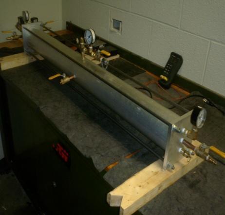
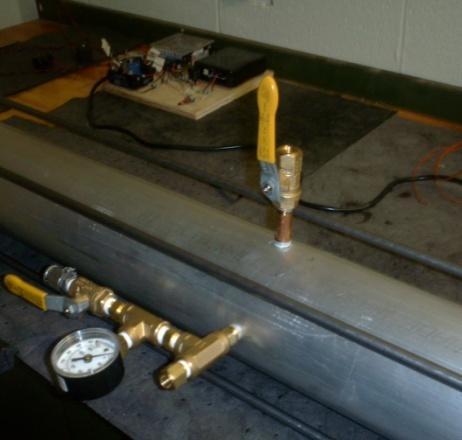
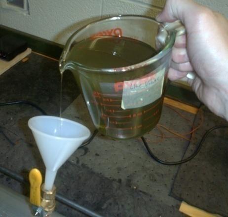

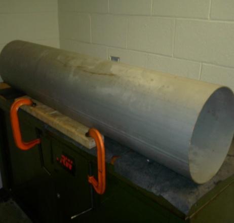
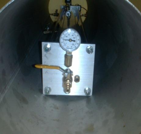
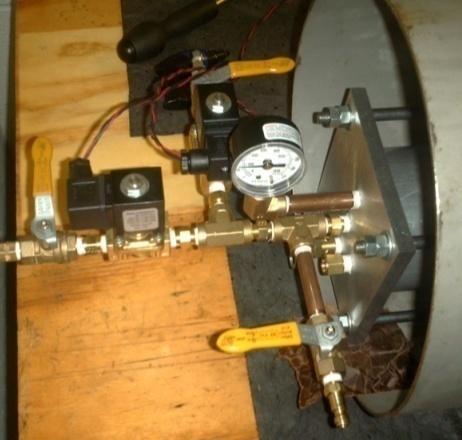
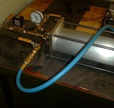
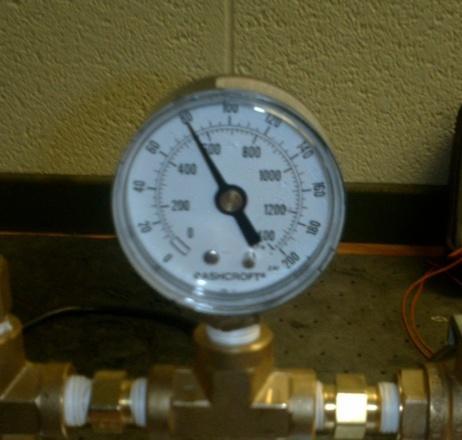
88
 Begin with the test fixture disassembled, meaning the endplates are detached from the cylinder. 1.")

 Place the piston and seal compressor on top of the cylinder. Ensure that the middle valve of the cylinder is open so no pressure builds up. 4.")

 Once all seals are inside cylinder, the ring compressor can be removed. 7.) For the concept piston, use the syringe to inject fluid into the pocket.")

89 The steps for each labeled picture are shown below: 0.) Begin with the test fixture disassembled, meaning the endplates are detached from the cylinder. 1.) If you are starting with a new seal, it will be necessary to use a piston seal compressor. We rented one from our local automotive supply store. Use it to compress the seals so they can fit into the cylinder. 2.) For the concept piston, ensure that the set screw is not installed on the piston during installation. 3.) Place the piston and seal compressor on top of the cylinder. Ensure that the middle valve of the cylinder is open so no pressure builds up. 4.) While ensuring the piston stays aligned, use a mallet and gently tap on the piston so it slides out of the seal compressor and into the cylinder. It may be necessary to let the piston rest inside the ring compressor for a while if you cannot get it to slide into the cylinder. 5.) Notice that the piston is almost all the way into the cylinder, but still inside the seal compressor. 6.) Once all seals are inside cylinder, the ring compressor can be removed. 7.) For the concept piston, use the syringe to inject fluid into the pocket. The pocket holds approximately 110 ml of fluid. 8.) Fill until the pocket won t accept any more fluid. Rotate the cylinder so that the piston is on an angle to try to release any air bubbles present. 9.) Wrap the concept piston set screw with thread seal tape before installation. Insert this screw so it is flush with the piston. 10.) Use a piece of wood to tap the piston down to the desired depth into the cylinder. 11.) For this test, the depth was 8 as can be seen in the picture. 12.) Repeat for the other side. Both pistons should be 8 deep in the cylinder. 13.) Install the endplates onto the cylinder. It is easiest to prop both endplates up on a piece of wood as shown to aid with aligning the cylinder and attaching the tensioning rods. 89
90 14.) Rotate the fixture so that the fill valve is the highest point in the system. 15.) Using a funnel and a beaker, slowly fill the system with fluid. It will take approximately 1.06 gallons of fluid. 16.) Once it is full, lift and lower both sides, one at a time, as shown. This will aid in air bubbles leaving the system. Keep topping the fluid level off as it lowers. Use the gas tester to extract fluid from the extraction port to remove more air bubbles from the system. Keep topping off the fluid while you pull fluid out with the gas tester. Once you are confident that most air has been removed from the system, close both valves. 17.) Insert the test fixture into the protective steel cylinder. Place pieces of wood on either side of the cylinder and secure with C-clamps so the cylinder cannot roll off the table. 18.) Pressurize both sides of the cylinder to 35 psi. Do this by incrementally filling each side 5 psi at a time until the pressure is reached. 19.) Open the solenoid inlet and exhaust throttling valves half way and turn on the control system. Adjust these valves so that the system fills to psi and then exhausts to 35 psi in one cycle. Ensure that the system does not fill or exhaust too quickly as the solenoid valves rely on the flow of air for cooling purposes. Cycle the system for 3 hours. 20.) After 3 hours, turn the control system off after the system exhausts. Ensure that each side reads 35 psi. This will ensure that the pistons are centered. After the pressure is equalized, incrementally fill each side by 5psi until a pressure of 80 psi is reached. 21.) Ensure that the middle pressure gauge reads 80 psi. This is necessary so that the fluid actually flows out without pulling a vacuum on it. Be very careful not to knock the filling valve open. An 80 psi pressurized fluid exhausting out of a ¼ valve would be dangerous. 22.) Attach the Stauff line to the extraction Stauff fitting. 23.) Attach the other end of the Stauff line to the Stauff fitting on the gas tester. 24.) Slowly lower the piston in the gas tester while monitoring the pressure. Do not let the pressure go below 0 psi. This may cause gas to come out of solution prematurely and ruin your measurement. Follow the gas tester procedure to measure the concentration of gas in the sample [6]. After sampling, depressurize the system in 5 psi increments alternating sides of the piston cylinder. 25.) After testing 2-3 samples from the test fixture, remove the endplates. Check for any fluid that may have leaked past the seals and make a note of it. 26.) Attach one of the tensioning rods to the piston. To get some of the fluid out, use this rod to push the piston back and forth (ensuring it doesn t cross the center line) while holding a container in front of the fill valve. 27.) To drain the rest of the fluid, place the cylinder on two chairs, tables, etc. and place a container below it. Open the fill valve and let the fluid drain out. Lift either side to aid in draining the fluid. After the fluid drains out, use the tensioning rod to pull the pistons out of the cylinder Design of experiments based on results This section discusses the various results that were obtained through testing and the reasoning that lead us from one experiment to the next. More detail for each day of testing can be viewed in Appendix K. The data output from the gas tester is a pressure measurement that results from a change in volume. Our first use of the gas tester on March 24 gave a pressure reading of 26.4 psi used to derive the gas concentration of the first bar in Figure 10.1 below. Upon measuring the same sample of tested fluid again we got a reading of zero. This brought to our attention that the gas tester has to remove the dissolved gas from a fluid sample in order to measure its concentration. Instead of trying to perform consistent experiments, we decided to vary certain parameters in our experiment to understand their effects on our results. 90

91 Figure 10.1: Gas tester trends of olive oil handling methods The measurements in Figure 10.1 show consistency in our use of the gas tester with two measurements of fresh fluid taken on most days for precision error. Figure 10.1 also shows the results of different methods of handling the olive oil after it has been tested. Tested samples left open to the atmosphere overnight had begun to acquire more dissolved gas, but at a decreasing rate after repeated tests. We assume its equilibrium concentration is that of the fresh samples, but we cannot confirm whether the tested samples are converging back to the fresh sample concentration. Another tested sample was sealed in a glass jar with an air-tight lid between tests and showed a trend of increasing convergence rate to equilibrium concentration. This was likely due to the slight pressurization of the jar upon the sample being sealed. On April 7 th, a week after observing theses trends, two samples were left overnight with one of the sample s container having the cap left off. The containers used for the April 7 th test were different than the containers used for previous tests. The April 7 th containers do not provide as tight of a seal and thus do not produce as high of a pressure difference when sealed. Due to the lesser seal quality, we expected and observed a smaller difference between concentrations of the open and closed samples. Initial reference piston force cycling is shown in Figure We began a reference piston trial after we took two measurements of the control concentration in fresh olive oil for the day. After one hour, we purged the line and took a sample of the force cycled olive oil as planned. We measured a very high gas concentration compared to the fresh samples. After cycling for another hour, we expected to measure an even higher concentration but the remaining samples went down to the uncertainty range of the fresh sample measurements. We began to suspect that our procedure for purging the line and removing free gas from the gas tester was throwing away free gas that may have permeated past the seals. From the beginning however, we assumed that any permeated gas would be in dissolved form. In an attempt to get permeation data, we decided to take samples by extracting from the highest point in the liquid chamber as opposed to the filling port, and also force cycled for three hours instead of one hour between samples. Only two three-hour samples, shown in Figure 10.2, could be taken due to time constraints. This did not improve our results. 91
![Gas Concentration [mol/gal] Figure 10.2: Initial reference piston trials were inconclusive After the first force cycling interval for three hours, we noticed the fluid was darker due to particulates.](/docs-images/82/86794656/images/92-0.jpg "We investigated the possibility that the very slight acidity of olive oil may be degrading one or all of the o-ring, seal rings, or glide rings.")
92 Gas Concentration [mol/gal] Figure 10.2: Initial reference piston trials were inconclusive After the first force cycling interval for three hours, we noticed the fluid was darker due to particulates. We investigated the possibility that the very slight acidity of olive oil may be degrading one or all of the o-ring, seal rings, or glide rings. Submerging these materials in fresh olive oil for a few days showed no particulate formation. Friction due to sticking was a possibly causing the seals to wear down and thus causing particulate formation. However, we never observed the settling of these particulates and after running some of the darkened fluid through a coffee filter, we did not observe any visible particles coming out of the olive oil. It is possible that when the seals become pressurized, the presence of olive oil causes the dye of the seals to contaminate the fluid. It is likely that the pressure causes the darkening of the fluid since the seals did not degrade in unpressurized olive oil. Up until April 2 nd, the transition from high to low pressure was smooth during force cycling. From this day onward, the pistons would stick, causing the transition from high to low pressure to not be smooth. The pressure dial readings would drop 10 psi during the stick for every oscillation. An initial measurement of the darkened olive oil seemed to show a much higher concentration than the fresh samples Sample without Cycling Sample from Fixture without Cycling Apr 7th Figure 10.3: Variance in successive test fixture samples without force cycling 92

93 We decided next to observe the variance of sample readings from continuous extractions of olive oil from the liquid chamber of the test fixture without force cycling. A concern was that the distribution of dissolved gas that may have permeated was not uniform in the working fluid. Shown in Figure 10.3, the first sample from the test fixture is both the largest and equal to the control measurement. The variance of successive measurements was used for precision error in our uncertainty calculations. Concentration measurements in Figure 10.4 show that some concentration measurements of the darker samples are higher than every fresh sample measurement. This is either because the gas tester interpreted the particulates as being dissolved gas or because the particulates increase the solubility of the olive oil. However, some later readings of dark samples were lower than fresh samples. Because of the trends in Figure 10.1, we anticipated fresh concentration measurements as low as the one for April 9 th in Figure 10.4 despite the apparently high solubility of darker olive oil. During pouring of the dark olive oil samples, we noticed dark clouds around where the bubbles would pop after rising to the surface. The distribution of the particulates is affected by air bubbles but we cannot confirm if the presence of particulates increases the solubility of olive oil or affects the distribution of dissolved gas. In the gas tester, rising bubbles would take longer to pop on the surface of the olive oil and thus grow larger. The particulates may increase the surface tension of the olive oil. We had enough fresh olive oil left to fill the fluid pockets of the concept pistons to see if the accumulation of particulates to make the olive oil dark was caused by the seals or the glide rings of the reference pistons. The fluid became dark during force cycling of the concept pistons as well thus concluding that the particulates are from friction on the seals. Figure 10.4: Contaminated olive oil gas concentrations were higher than those of the consistent fresh samples To address our concern that fresh olive oil may be too saturated to absorb any permeated gas to begin with, we began shaking olive oil in the gas tester without taking measurements so that we could collect a large enough volume of flat olive to fill the test fixture enough for at least one sample. Although use of the gas tester on an olive oil sample twice in a row would yield a gas concentration of zero, this preparation method on up to a dozen samples mixed together would not always be zero. We therefore took an initial reading of the supply of flat olive oil before force cycling. Figure 10.5 below shows the reference piston trial results of our taking an initial concentration reading and then taking samples after 3 hours of force cycling. 93
94 Figure 10.5: Reference piston force cycling yielded higher dissolved gas concentrations The April 7 th flat olive oil supply in Figure 10.5 was force cycled for 3 hours, and was measured to be at a higher gas concentration still within the bounds of uncertainty. The remaining cycled fluid was left sealed in the test fixture overnight at 5 psi and then measured again the next morning. The increase in gas concentration could have been caused by the presence of air bubbles in the liquid chamber of the test fixture due to imperfections of our filling process, or from steady state post-permeation effects. These overnight pressurization measurements were our way of measuring free gas in the liquid chamber since the fixture cylinder is not transparent. In recognizing the possibility of a leak, the observed change in pressure due to free gas in the liquid chamber is an underestimate. These overnight pressurization measurements are taken after force cycling with the exception of the night of April 12 th shown in Figure On April 12 th, shown in Figure 10.6, we filled the test fixture with flat olive oil and took an initial measurement. We then left the test fixture slightly pressurized overnight without cycling beforehand to see if we would get a change in dissolved gas concentration similar to the post-cycling overnight pressurizations. The gas tester psi reading increased from 0.9 to 5.3 psi while the liquid chamber pressure dropped by 2 psi. Leaks and gas dissolving could have caused this added concentration increase despite no force cycling. Dr. Moskalik informed us that most seals have a minimum pressure at which they seal, so it is possible that we reached this minimum and air leaked past the seal overnight. In another test where we left the system pressurized at 80 psi overnight, we did not notice an increase in gas concentration. We feel that this is a clear indication that force cycling is necessary to induce permeation past the seal. The April 8 th measurement in Figure 10.5 and Figure 10.6 show that there was both a small amount of permeation and that there was no trapped free gas in the liquid chamber. None of the permeation we measured was in the form of free gas. Time constraints encouraged us to force cycle the concept piston without bothering to increase our degree of confidence that what we measured for the reference piston was indeed permeation. 94
95 Figure 10.6: Permeation measurements for the concept piston varied significantly compared to the reference piston Figure 10.6 shows that on April 12, after force cycling for 3 hours with the concept pistons, we had enough flat olive oil to take three measurements that all showed permeation beyond uncertainty. This encouraged the conclusion that the concept piston is simply not a good idea. Two more trials the next day showed an increased performance of the concept piston. The measurements of the first trial on April 13 th were compared to the dissolved concentration we measured from overnight pressurization as opposed to the flat sample reading taken before leaving the prepared test fixture overnight. The third and final concept piston trial showed an increase in concentration that failed to exceed uncertainty like the previous trial Summary of Results This section will outline the major findings and results from our testing: For the duration of our testing, the olive oil visibly darkened. We feel that this is due either to the friction of the seals against the piston cylinder during testing or from the pressurization of the seals. We concluded that the seals do not degrade when placed in olive oil that is not pressurized. We also confirmed that it was indeed the seals that were causing the olive oil to darken and not the wear rings. When left in a jar with an air tight seal lid overnight, the rate at which the gas concentration of the olive oil converged to its original concentration tended to increase with subsequent samplings. When left open to the atmosphere overnight, the rate at which the gas concentration of the olive oil converged to its original concentration tended to decrease with subsequent samplings. When left pressurized overnight in the piston cylinder at a low pressure, the concentration of gas in olive oil tends to increase. However, when left pressurized overnight at a high pressure, the concentration of gas in olive oil does not change. This may be due to properties of the seal. The seal may require a higher pressure to work properly, thus when left at the lower pressure the seals were not working properly. Thus, it can be concluded that force cycling is necessary to induce permeation. From the data that we have collected, the concept piston, in its current state, does not seem to provide a significant reduction of permeation. On a per seal basis, the reference piston is the better design. This is counterintuitive because one would assume that two seals are better than one. Design improvements to the concept piston can be found in the next section. 95
96 11 DISCUSSION After working with our fixture for well over 50 hours, we have noticed several strengths and weaknesses in the design we created. The following sections provide details of what we noticed while testing our fixture Design Strengths The design we created performed very well, and we feel it worked exactly how it was designed to. This is evident through the fact that we met eight of the nine engineering specifications that were set at the beginning of the project. A table with the engineering specifications and how they were met can be seen in Appendix D.6. The specific strengths of our project are listed below, with more detailed explanations following. 1. Control system 2. Reference piston 3. Prevented leakage 4. Robust and safe design One of the specific design strengths of the fixture was the control system we developed. Through assistance, we were able to develop a system that was very simple and cycled between the solenoids as desired. Calibration testing of this system took less time than we had anticipated, which in the end allowed us to test the pistons longer. A somewhat unexpected benefit of the control system was the fact that we never had to change the code in the Arduino board. Originally, we had thought we would have to change the cycling times for the solenoids when testing conditions changed. We determined all that needed to be done was change how much the throttling valves were either opened or closed. We knew the throttling valves would control the air flow; however we had not expected them to essentially act as a secondary controller, controlling the pressures of the system. Again, not having to change the code for the Arduino board every time we changed testing conditions allowed us to test the pistons for a longer period of time. We were also extremely pleased with the design of the reference piston, and how well it cycled in the piston cylinder. While we did model the design after the current EPA design, there were still no guarantees that the piston would run smoothly. When the reference piston was placed in the piston cylinder for the first time, after calibration testing, it ran perfectly. We had originally expected it to take some time to refine the cycling and get it to work properly. Because we had designed the piston to stay aligned and manufactured it to the proper tolerances, it worked the first time. By spending a little extra time on the design portion, we were able to save much more time on the testing portion of the project. Although it was one of the main tasks of the test fixture, we were very pleased with how well it retained pressure and prevented leakage. During the initial calibration testing when we left the fixture pressurized for an hour, we only noticed a 2.5 psi drop. This is impressive, considering all the fittings that were installed on the test fixture. The o-rings and tensioning rods performed well to retain the pressure, while the NPT threads with thread tape also did their part to hold the pressure. Throughout testing, we did not have any leakage of olive oil, and only minimal leakage of air pressure, which was small enough that it did not affect any of the testing results. Another one of the main tasks of the test fixture was that it should be able to stand up to repeated cycling and remains safe while doing so. Throughout the testing procedures (which totaled to more than 30 hours), we experienced no safety concerns with the test fixture. Also, we did not notice any degradation of any of the components. This shows that the test fixture was very well designed, and it can handle 96
97 varying pressures and the forces it experiences because of these. We feel confident that the test fixture can last for a much longer time, so it will still be of use if further testing on the pistons is to be done Design Weaknesses While our design was very successful, there are some points of our design that we felt could have been a little better. The weaknesses of our design that we determined are listed below, with more detailed explanations following. 1. Lack of ability to see inside piston cylinder during cycling 2. Long time needed to fill/empty the test fixture 3. Long time needed to assemble/disassemble the test fixture 4. Concept piston did not cycle smoothly in the piston cylinder 5. Ball valves were vulnerable to being accidentally opened During the design process, we opted to use an aluminum cylinder, with the knowledge that we would not be able to easily see any air bubbles or see the pistons cycling. While we tried to resolve this situation by installing sight glasses, these turned out to be relatively useless. They did allow us to verify the pistons were moving, however we could not tell exactly where they were in the cylinder, or how they were cycling. The sight glass installed to help visualize air bubbles also was not very helpful, because we assume that some of the air bubbles were trapped against the aluminum cylinder, and we were never able to see them. With all the possible situations that were going on inside the cylinder, it was very difficult to analyze the results without seeing inside. Another weakness of the test fixture is the amount of time it took to fill and empty the test fixture with the olive oil. In the design we created, we only had one valve that we could fill or empty the interior of the piston cylinder with. The issue with this is that when filling, air would have to escape through the same valve the olive oil was being poured into. The same happened with emptying, where air would have to enter the same valve the olive oil was exiting. Because of this, every time we would either fill or empty the test fixture, we would have to be careful to pour the olive oil slowly, to ensure air could properly enter or exit the fixture. If we poured too fast, the air would be forced through the olive oil, and cause it to spill slightly. While this is not a major safety concern, it did take time, and caused us to lose some olive oil. After the lengthy process of removing or filling the piston cylinder with olive oil, it took a great deal of time to actually disassemble the test fixture, which is another design weakness. To assemble or disassemble, eight nuts needed to be tightened or loosened, and then the endplates had to be properly arranged or removed. This entire process took approximately minutes, and while it does not seem like a lot of time, doing this twice a day added up. If we could have designed this process to take slightly less time, we would have possibly had additional time to test the pistons, and acquire more data. Although we did not actually create the design for the concept piston, we did find some weaknesses with it through testing. When designing the reference piston, we had a dual glide ring design to prevent the piston from misaligning in the piston cylinder, and ensure it cycled smoothly. The concept piston had a dual seal configuration, and initially, we thought the seals also would act as a glide ring. When we did tests with the concept piston, it would occasionally stick in the tube. Because this did not happen with the reference piston, we hypothesize that the lack of glide rings on the concept piston were the reason for it sticking. The sticking that occurred for the concept piston could have been one of the reasons why the results we got were inconsistent. We predict that if we corrected the piston so it could not misalign in the piston cylinder, the results would be much more consistent. During the testing procedures, we noticed that some of the ball valves were in a vulnerable location, and if accidentally bumped, they could open. For some of the valves, this would not have been a problem, 97

98 however for valves such as the ones in the center of the fixture, this could pose a sever safety concern. If the filling valve were to accidentally open while the fluid inside the cylinder was pressurized, it would come out of the fixture very quickly, and likely cause a great deal of damage. We noticed this safety risk early on in the testing, and were very cautious around the risky valves, to ensure we did not accidentally open them Design Improvements Although our test fixture worked extremely well, based on the discussions above, there is still a fair amount that could be improved on our fixture to make it even better. Table 11.1 below shows the design improvements we would implement if we were to work further on this project, with specific details in the following sections. Current Design Aluminum cylinder Single filling/extraction valve Tension rods with nuts Dual seal concept piston Standard ball valves Design Improvement Aluminum cylinder with sight windows Additional valve for air inlet/outlet Quick connect/disconnect tension rods Dual seal with dual glide ring concept piston Locking ball valves Table 11.1: Design Improvements Aluminum cylinder with sight windows Aluminum was chosen over clear material for the piston cylinder due to the strength and the ability to tap into it to mechanically attach the filling and extraction ports. As discussed above, though, it was a significant disadvantage not being able to see inside the piston cylinder. To resolve this issue, we would create a hybrid piston cylinder design, which would consist of a clear material and aluminum. The clear material could possibly be polycarbonate, as it would have the strength to withstand the pressures the system would experience. The design would likely entail a metal portion that would be installed in between two segments of polycarbonate. This metal portion would need to have an internal diameter equal to the external diameter of the polycarbonate. It would also need internal o-rings to ensure it remains sealed, and screws could attach the metal to the polycarbonate. The filling and extraction ports would be threaded into the metal portion, so the polycarbonate would not have to be threaded into. This resolves the safety concerns of threading into polycarbonate; however the inside of the test fixture can still be viewed. A preliminary drawing of this concept can be seen below, and would contain the endplates and tensioning rods that were used in the current design. Figure 11.1: Hybrid design for piston cylinder 98


99 Additional valve for air inlet/outlet To expedite the fluid filling and extraction process, we would add a third valve somewhere in the center of the piston cylinder. This valve would allow for air to exit while filling and enter while extracting. This would eliminate the need for the air to exit/enter the valve which the olive oil is entering or exiting, meaning the olive oil can be poured at a quicker rate Quick connect/disconnect for tension rods To allow for quicker fluid/piston changing, one of the things that we would change is the method of attachment of the tensioning rods. In the current design, you must remove eight nuts from one endplate and then move all of the rods out of the way in order to access the pistons. If we were to redesign this mechanism, we would employ aircraft cable instead of steel rods. The steel rods were often in the way, so have a cable that can be moved out of the way would be ideal. In order to secure both plates together, we would employ pull clamps. This mechanism would make the process of taking the endplates off much easier and quicker. Figure 11.2: Schematic of tensioning rod redesign [18] Dual seal and glide rings for concept piston To resolve the problem of the concept piston misaligning in the piston cylinder, we propose adding two glide rings on the outside of the piston seals, as shown in Figure The additional glide rings would cause the concept piston to increase in length, which would in turn alter the aspect ratio. The aspect ratio would no longer match the current EPA piston design; however we do not feel that is significant. We feel it is more important to ensure the piston remains aligned and can cycle smoothly through the piston cylinder. We predict this will provide better data, so in the long run it can be determined if this is a better design or not. Figure 11.3: Proposed new concept piston design 99

100 Locking ball valves To resolve the issue of the ball valves being accidentally opened, we suggest the use of locking ball valves. They have all the same properties and strength as the standard ball valves, with the difference being a padlock can lock the valve in the closed position so it cannot be opened accidentally. Figure 11.4 below shows the recommendation for future ball valves. Spring-close lever ball valves also exist, however these can still be accidentally opened if bumped into, so they do not resolve the issue. Figure 11.4: Lockable lever ball valve [19] 12 RECOMMENDATIONS After cycling the pistons for over 30 hours and analyzing the results, we have some recommendations if further work is to be done on this project. Aside from making all the design changes as mentioned in the previous sections, additional recommendations are listed below, with further details in the following sections. 1. Test the concept piston while locking the expansion/contraction ability 2. Test the pistons for a longer duration 3. Test the pistons at a higher pressure difference 4. Continuously inspect test fixture for flaws One of the tests we were unable to perform due to time constraints was to restrict the ability of the concept piston to expand or contract. This test would be valuable to perform because theoretically, the permeation results compared to the reference piston should be half. This is because with this test, it would basically be testing one seal versus two seals, and it would be expected that two seals should perform better. Because we got some strange results while testing that we felt were a little counterintuitive, it would be valuable to run this test to ensure our assumptions are correct. Once this test is performed, the results from the restricted concept piston could be compared to the normal concept piston, and the affect of the expansion and contraction could be analyzed. Another testing procedure we would alter would be to test the pistons for a longer period of time. With current results, the differences between the concept piston and the reference piston permeation values are essentially the values of the error. In Figure 12.1, the data points above zero represent samples that have shown permeation beyond the bounds of uncertainty. While using our engineering judgment, we were able to come up with a conclusion; we feel that through testing longer, differences in permeation rates would increase beyond uncertainties. This would conclusively provide the result for which piston design performs better. Based on the mathematical model we have created, it predicts that running a test for four hours straight would change these permeation rates enough so they are no longer the same when error is factored in. Under the assumption that the dissolved gas concentration of olive oil in our test fixture increases at a linear rate during force cycling, estimates of the additional time required to confirm 100
101 permeation for each sample are summarized in Figure Note that samples that do not need additional time are negative in Figure It is important to note that the mathematical model is more accurate for the reference piston as opposed to the concept piston. This is because it is still relatively unknown how the concept piston acts, so creating an accurate mathematical model is very difficult. Keeping this in mind, it might be wise to run a test longer than four hours, to ensure the difference in permeation develops. Figure 12.1: Half of trial concentration measurements did not confirm permeation beyond uncertainty Figure 12.2: Cycling durations 1 hour longer would have almost doubled the number of permeation measurements that are beyond uncertainty 101
102 Aside from testing the fixture for longer periods of time, we also feel that testing the fixture at a greater pressure, and therefore greater pressure difference, could increase the permeation values. The solenoids have the minimum pressure rating for the entire test fixture, 150 psi, so this is the absolute maximum pressure the current design could be tested at. We recommend testing at a slightly less pressure than this, 135 psi, to ensure the solenoids remain in working condition. With this 135 psi high pressure, we suggest the lower pressure to be approximately 50 psi, to keep the same aspect ratio. With this higher pressure difference, we would expect to see greater permeation values according to Equation 9, and the difference between the concept piston and the reference piston should become more evident. Lastly, we feel it is very important to continuously inspect the test fixture to ensure it is in proper working order. Some specific components that should be looked at are the o-rings on the endplates, piston seals, all threaded components, and the piston cylinder. While this design has a very long fatigue life, it is possible that some flaws in the materials could cause early failure. The o-rings on the endplates should be inspected to ensure they have no flaws or plastic deformation, so they can perform their job and hold pressure in the system. The piston seals should also be inspected to ensure they do not develop any flaws that might alter the permeation values. The threaded components should be inspected to ensure the threads are still intact. The thread seal tape should also be replaced when it looks deteriorated, to ensure the threaded connections keep the pressure vessel sealed. Finally, the piston cylinder and tension rods should be inspected to see if any flaws are developing. The piston cylinder has a large critical crack length, so if a large crack develops, it should be addressed before further testing is performed. 13 CONCLUSION Growing global energy demands, global warming effects, and diminishing fossil fuels have been motivation to improve current power-train technologies to make them more efficient and cost-effective. With an emphasis currently on urban delivery vehicles for the United Parcel Service (UPS), the Environmental Protection Agency (EPA) is improving hydraulic hybrid technology. The current design uses a high pressure system, with nitrogen gas and hydraulic fluid in an accumulator. A single seal piston in the accumulator separates the gas and hydraulic fluid; however the gas can permeate past the piston and into the hydraulic fluid, causing damage to the system components due to cavitations. An innovative design by a previous ME450 team was developed to solve this problem. This piston seal design was never validated due to test fixture design flaws. Our task for this project was to create a test fixture for their piston design, and conclude whether the design should be further developed, or if the concept does not work as planned. Through the duration of the semester, we followed a very strict schedule to allow for us to have adequate time for testing the piston design. We manufactured a test fixture that uses compressed air to cycle the pistons back and forth. We also manufactured two sets of pistons, a set of the concept pistons that were designed by the previous ME450 team, and a set of reference pistons, which are similar in design to the pistons that the EPA is currently using in their accumulators. Creating the two sets of pistons instead of one allowed for us to conduct a much more valuable series of tests. The two piston designs are compared directly, under the same conditions, in our test fixture. We began our testing with preliminary testing to ensure fixture safety and reliability. We first pressurized our fixture without a control system and then cycled air in and out using the control system, but without pistons. We then began preliminary testing with the pistons to refine our testing procedure to ensure the best results possible. We decided that it would be best to test the reference piston first because it is more predictable. If we could not measure any permeation with this piston, then we would not be able to conclude anything about the concept piston. Initially, we conducted our testing with our test fixture full of fluid, which would allow for four cycling periods and four samples to be taken. After conducting this test multiple times, we realized that we were not observing any notable permeation of gas into the fluid. We 102
103 decided to run a test to validate the gas tester to ensure that it was our testing procedure and not the gas tester that was causing our results to be inconclusive. We did this by taking repeated samples from the same fluid source: the gas tester produced very consistent measurements. We then continued our testing by reducing the volume of fluid inside the test fixture and increasing the sampling time, in hopes that it would expedite the permeation that we could observe with the gas tester. This testing produced noticeable permeation results and could be repeated to produce fairly consistent results with the reference piston. We then set up an identical test with the concept piston in order to make a direct comparison to the reference piston. The permeation results noticed by the concept piston were very unpredictable and in its current design state, the concept piston does not produce significantly lower permeation results than the reference piston. In order to reach a definite conclusion as to which piston is the better design, further testing must be conducted. There are many variables that need to be quantified in order to reach a definite conclusion. For instance, the concept piston should be redesigned with glide rings in order for it to cycle smoothly, as the reference piston did. It is unclear whether the bumpy movement of the concept piston is causing the sporadic results that we observed. The testing periods for both pistons should also be increased in order to produce results for the two designs that are not within the error ranges of each other. From the data that was collected, we were able to calculate a rough approximation of the amount of moles of gas that could be expected in the current full scale accumulator. With a 95% confidence level, we approximated this to be 11, ,000 moles of gas. This number is approximated over 10 years and is 11,000 based off of the data that we collected, which has a large standard deviation due to limited tests. Thus, there is a large amount of error in this number and it does not meet our engineering specification of ±100% error. The calculations that lead to this number can be seen in Appendix J Scaling using Equation 8 in Section could have also been attempted. Because this analysis was meant for scaling of concept piston permeation data, we did not use this derivation. We observed unpredictable concept piston performance for too few data points. Overall, we had a very successful project; we maintained a stringent schedule, met eight of our nine engineering specifications, produced a working test fixture, and provided insight into additional tests, that could be conducted that require no modifications to our test fixture, to provide more conclusive results for the EPA. While we didn t close the book on the concept piston, we have provided the EPA with significant knowledge about gas permeation and concentration in fluid, and information as to what needs to be done in the future to produce conclusive results. We are providing the EPA with a fully functional testing device that can be reused in its current state to produce better results. : It is not possible to have negative permeation in the system, thus the difference in plus and minus errors 14 ACKNOWLEDGEMENTS We would like to thank the following people for their assistance with our project: Dr. Andrew Moskalik, of the EPA National Vehicle Fuel Emissions Laboratory, was accommodating from the beginning about making sure we understand the background of hydraulic hybrid technology, and the potential for us to make a lasting contribution to research in developing this technology. This motivation along with productive meetings played an important role in our success. Professor Gordon Krauss, Section instructor in ME450 at the University of Michigan, held and maintained high expectations of us. This encouraged us to maintain the high performance we began the semester with. Anticipation of future project challenges was essential for our especially tight fabrication and testing schedule. 103
104 Matt Navarre, Lisa Stowe, and Merlis Nolan encouraged us to be very organized about developing a safe test fixture, report, and experimental procedure. The necessity of having a safe, incident-free senior design project was instilled in our design specifications and personal objectives to earn us a testing facility for an adequate duration of time for us to be successful. We are grateful to have had John Mears around during winter break to refresh us in use of the lathe, snap off the locks so we could run the machines, and take care of CNC machining processes. Bob Coury and Marv Cressey also provided us with great advice during the assembly process and didn t hesitate to supply us with hoses, extension cords, a place to store our test fixture, and any materials we needed for testing. John Baker was very helpful in the setup and calibration of our control system. We were also able to borrow a casing for the design expo to make our control system more safe and presentable. Charlie Weger was our testing supervisor. He made sure we always had access to our testing facility and provided assistance so that we could smoothly clean up our testing facility and dispose of olive oil. 15 INFORMATION SOURCES To gain more knowledge and insight into our project as well as the fundamentals behind the engineering problems at hand, we consulted various sources of information, including patents, previous ME450 reports, and experts in the areas of interest for our project. Other sources include fluid mechanics text books, theoretical models of similar experiments, ISO registered websites for seals and engineering applications, and specification sheets of potential parts. The primary information gap was whether or not the concept piston would function the way it was intended to. More research and experiments are necessary to predict what will happen in the fluid pocket of the concept piston under the conditions simulated in the test fixture. Persistent effort on utilization of gathered information sources should be sufficient to fill the information gaps Patents and Literature Review In our research, we found four patents to help us with understanding multiple ways to design a test fixture to cycle a piston and measure gas permeation. They include an apparatus for dissolved gas in a liquid [20], a liquid pumping system [12], a hydro-pneumatic accumulator [21], and a method for determination of relative gases in liquids along with their densities [22]. In researching these patents to come up with ideas for our test fixture, we gathered five essential functions for measuring the amount of gas in a liquid cycled by a piston multiple times. For the apparatus of each patent, there were valves for allowing liquid and gas to enter and exit the test fixture. Devices for measuring temperature and pressure were also consistent since each apparatus used changes in volume, temperature, and pressure to get moles per unit volume of dissolved gas in a liquid. The fifth function is the force required to cycle the piston to see changes in pressure and volume. Since the method of force actuation is what differentiated the devices the most, deciding on the force actuation method is going to be critical in our design process Physical Laws Research of relevant patents helped us develop an understanding of how fluid properties are related. A fluid under increased pressure will have higher gas solubility. An increase in fluid temperature will increase its pressure if it is enclosed in a fixed volume. A fluid s capacity to store energy decreases as density increases. Helium, for example, is capable of storing much more work energy than air due to compression since it is less than 14% the density of air [21]. In whatever configuration we decide to arrange components in our test fixture, we will likely use the equations below to measure gas permeation around the piston design concept subject to our evaluation. 104
105 n = P P V V gas RTV liq n = gram-moles of gas dissolved per ml of liquid P = pressure reading in cylinder [atm] P V = vapor pressure of liquid constituents [atm] (sample temperature) V gas = gas volume in cylinder [ml] R = universal gas constant [atm-ml/gram-moles/deg] T = absolute temperature [K] V liq = liquid volume [ml] Eq.1 P Tot = P Air + P v,water + P v,oil P N2 = y N2 P Air Eq.2 P Tot = measured pressure reading P Air = air pressure P v,water = water vapor pressure present in the air P v,oil = oil (test liquid) vapor pressure present in the air y N2 = molar concentration of nitrogen in air P N2 = partial pressure of nitrogen Possible Component Arrangements Three of the devices in these patents used a piston cylinder driven by the liquid to apply pressure to the gas. The liquid pumping system, however, included a piston driven by a motor to pump a fluid while the two translational walls of the fluid chamber could measure the compressibility of the fluid. This is achieved by maintaining the pump (set-up shown in Figure 15.1is referred to as the pump) in a sealed state. The actuating piston is set to a specified position, as controlled and measured by a motor and an optical shaft encoder or Linear Variable Differential Transformer (LVDT) depending on the user s preference. Two check valves, as shown in Figure 15.1 below, allow for fluid to be delivered during downward movement and exhausted during upward movement of the piston. When the piston is set to a desired volume, liquid is inputted. After inputting liquid, the volume and pressure are measured by the change in piston height and pressure transducer. By sensing the piston position during testing, the volume change can be calculated and thus the compressibility of the fluid can be determined. This concept is interesting and applicable to our project in the method of actuating a piston, and at the same time releasing and permitting liquid delivery. Figure 15.1: Schematic of patent showing force actuation on the liquid [23] 105
106 A potential problem with this setup is that it would be much more difficult to fabricate than to simply apply pressure using adjustable shop air on either side of the liquid chamber. Our team plans to do more research to determine whether or not applying shop air to cycle the concept-pistons and the liquid chamber accurately reflects the forces experienced in the full scale system. A set of fixtures that more closely resemble the hybrid hydraulic system is the model hydro-pneumatic accumulator [21]. These fixtures include a low pressure reservoir shown in Figure 15.2 below. Because the hydraulic accumulator system in UPS trucks has a low pressure reservoir, these fixtures are relevant to design possibilities. Figure 15.2: Schematic of patent fixture closely resembling the system of an HHV The fixture in Figure 15.2 is used to determine the amount of energy that can be stored in various gases. The two devices use a cylinder and piston to pressurize a gas. An oil of choice is pumped into the cylinder via pump or motor to create pressure. As mentioned above, this device was merely used as a foundation for concepts involving a high and low pressure reservoir. The apparatus function was ignored, while the components and circuitry of piping were valuable for concept generation Previous ME450 Team Resources The EPA has sponsored other student projects at the University of Michigan to help further experimentation in hydraulic hybrid vehicles. Recent student projects include a device for measuring free and dissolved gas concentrations in a liquid and the previously mentioned novel piston seal design to minimize permeated gas around a piston-style accumulator. Figure 15.3 shows the dissolved gas tester prototype and Figure 15.4 shows the piston seal test fixture prototype. Dr. Moskalik informed us that we may use the gas tester device to measure the gas content of the hydraulic fluid in our test fixture. The device essentially draws in a specified amount of liquid and then measures the pressure and temperature at various volumes using a pressure gauge and thermocouple. Using the ideal gas law and partial pressures, various calculations are made with the volumes, pressures and temperatures recorded to determine the concentration of gas dissolved in the liquid. The group that made the piston seal test fixture focused most of their efforts on the design of the piston seal configuration and did not have the time or resources to fully test their prototype. The test fixture prototype that they manufactured cycled the two pistons back and forth in an acrylic tube. There is hydraulic fluid in the cavity of each piston as well as in between the two pistons. There is air on both ends 106


107 of the tube. The air on one side of the tube is pressurized and depressurized with compressed air using a solenoid valve. The other side acts as the nitrogen gas in the full scale system and is compressed when the solenoid is pressurizing the system and is decompressed when the solenoid releases the pressure. Thus, the fixture was an attempt to efficiently model the full scale system, and we have agreed that it s a valid approach to evaluating the piston design concept. To measure the amount of gas that permeates into the hydraulic fluid, the previous team initially had the thin vertical cylinder full of hydraulic fluid as shown in Figure As the pistons cycled, their thoughts were that the gas would come out of solution and would end up in the top of the thin vertical cylinder, thus displacing the hydraulic fluid. However, at the start of their initial testing, the top of the vertical cylinder blew off as the system was pressurized and hydraulic fluid contaminated the assembly room. This incident ended their testing and they were unable to validate their design. Figure 15.3: Hydraulic fluid dissolved gas tester [6] Figure 15.4: Accumulator piston seal design rest fixture 15.3 Expert Assistance It was unknown what assistance would be needed early in the project, but there a few experts that have already been identified. Our sponsor, Dr. Andrew Moskalik, has a great deal of knowledge on our project, and we were in touch with him throughout the semester when we needed to learn more about a subject. Volker Sick, Professor at the University of Michigan, researches combustion in engines. Because the design we are working with involved pressure and cylinders, with similar concepts to engines, he is a valuable asset if questions arise. We discussed accurate measurements of the volume in a piston with him and he has given some valuable measurement suggestions. He has also suggested we talk with John Hart, Professor at the University of Michigan, because he uses high resolution cameras that might be useful to accurately measure the volume of the piston cylinder. 107
108 Aside from internal resources, there are a few external resources that have been identified that could possibly provide assistance. Trelleborg Sealing Solutions specializes in piston seals, and their product was used on the previous piston concept. We have determined that new piston seals will likely be needed, and keeping with the design the previous group created, we used the same seals (possibly scaled down). To ensure we worked with the seals correctly, we kept in contact with Trelleborg. To assist us in selecting a proper seal for the pistons in our test fixture, we have been in contact with numerous seal manufacturing companies. The original seal we were looking to purchase, and was used by the previous ME450 team, had both a high cost and lead time. These constraints encouraged us to look at alternative seals. We have been in contact with engineers at Trelleborg to discuss some of the seals they have available, and obtained data about them to be able to produce a test fixture that is reliable. We have also been in contact with sales people at Zatkoff Seals and Packings. They are a major distributor of seals, and they have been a valuable asset to us by assisting us in finding seals that both work well and fit into our time and budget constraints Working Fluid Properties The properties of hydraulic fluid, olive oil, nitrogen gas, and air are all very important to experimental setup, procedure, and anticipated analysis of results. The full scale system uses hydraulic fluid to pressurize the nitrogen gas. In the test setup, we used olive oil to compress the air. The use of olive oil instead of hydraulic fluid expedites the permeation process as well as improves safety. As will be discussed below, olive oil and hydraulic fluid have similar properties, especially in density and viscosity. While similar viscosities and densities are important for the substitution of the hydraulic fluid, the dissolution of nitrogen in the fluid is also important. Hydraulic fluid has the ability to dissolve more nitrogen than olive oil. Thus, when subjected to testing conditions, the olive oil should saturate at a faster rate than hydraulic fluid would. This will allow for a shorter test time. Also, since hydraulic fluid is considered a hazardous substance, the use of olive oil will be much safer for the test environment as well as the users of the device Hydraulic Fluid The hydraulic fluid that is used by the EPA in the full scale hydraulic hybrid system is Mobil 1 Synthetic Automatic Transmission Fluid. The main properties of concern for the fluid can be seen in Table These numbers come directly from Exxon Mobil [24] Olive Oil The properties of olive oil can be seen in Table Olive oil cannot absorb as much gas per volume as hydraulic fluid can [6]. Due to this difference, when subject to the same conditions, the olive oil should saturate more quickly than the hydraulic fluid. This is what will allow for a shorter testing period using olive oil as opposed to using hydraulic fluid Nitrogen Gas Nitrogen gas is used by the EPA in the high pressure accumulator of the hydraulic hybrid system to store the energy created when the vehicle is braking. This stored energy is then used to propel the vehicle forward upon acceleration. The basic properties of nitrogen gas can be seen in Table 15.1 on the next page Air Air consists mainly of oxygen and nitrogen. Percentage wise, dry air is approximately 22% oxygen and 78% nitrogen. Air has many other components including argon, carbon dioxide, neon, and helium, but the molar concentration of these are all less than 1% and are insignificant for our purposes. Because nitrogen has a larger molar concentration in air than oxygen, it will also have a larger partial pressure than oxygen. 108
109 When subject to a certain pressure, the nitrogen will have a partial pressure equal to 78% of the total pressure, while oxygen will have a partial pressure equal to approximately 22% of the total pressure. The partial pressure of nitrogen is what will drive it across the seals in the test fixture. The similar properties of nitrogen and air, shown in the table below, help justify the use of shop air for force actuation and gas compression chambers. Quantity Fluid Type Hydraulic Fluid [24] Olive Oil [6] Nitrogen Gas [4] Air [4] Dynamic Viscosity 6.415e-4 at 104 F 1.754e-3 at 68 F 3.727e-7 at 68 F 3.500e-7 at 68 F (lb s/ft 2 ) Kinematic Viscosity (ft 2 /s) 3.907e-4 at 104 F 9.826e-4 at 68 F 1.668e-4 at 68 F 1.360e-4 at 68 F Density (slugs/ft 3 ) at 59 F at 68 F 2.208e-3 at 68 F 2.571e-3 at 68 F Table 15.1: Properties of relevant fluids 16 REFERENCES [1] Deaton, Jamie P. How Hydraulic Hybrids Work HowStuffWorks, 30 Oct Web. 13 Jan < [2] Hydraulic Hybrids The Most Efficient Lowest Cost Hybrids, U. S. E. P. Agency, Ed., ed, [3] O Brien Corporation. Seamless vs. Welded Tubing Web. 3 Mar [4] Munson, Bruce R., Donald F. Young, and Theodore H. Okiishi, Fundamentals of Fluid Mechanics, Fifth Edition, Hoboken, NJ: John Wiley & Sons, Inc., 2006, [5] Engineering ToolBox. Google, Web. 16 Feb < [6] ME450 Report W09 Project 23: Hydraulic Fluid Dissolved Gas Tester, Brian LaFrence, Kyle Safford, Casey Timmons, Matt Feinstein, 2009 [7] Dr. Baer, "Gas Physics/Diffusion." GasPhysics.doc. Google. Web. < pressure+versus+diffusion+rate>. [8] Department of Chemical Engineering. Membrane Gas Separation. Rowan University, n.d. Google. Web. 24 Feb < [9] Kaviany, Massoud. Principles of Heat Transfer. New York: John Wiley & Sons, Inc., [10] Problem Solving Products Inc. Vacuum Permeation. ISO, Web. 17 Feb < [11] Vacuum Technology, Inc. Leak Rate Units and Conversion Factors. VTI, Web. < 109
110 [12] Plesset, Milton S., and Din-Yu Hsieh. Theory of Rectified Diffusion of Mass into Gas Bubbles. J. Acoust. Soc. Am. ed. Vol. 33. Pasadena: California Institute of Technology, Web. 19 Feb [13] Trelleborg Sealing Solutions, Mr. Delin Kleine, Phone: [14]Engineers Edge: Solutions by Design, n.d. Web. 10 March < [15] Engineers Edge: Solutions by Design, n.d. Web. 10 March < [16] Cutting Tool Engineering, Plus, n.d. Web 10 March < [17] University of Michigan. Mechanical Engineering Department. Mr. John Baker, 1107 GG Brown, Phone: [18] McMaster-Carr < [19] McMaster-Carr < [20] S. Gowing, "Apparatus for Determining Amount of Gases Dissolved in Liquids," United States Patent, [21] Gratzmuller, "Hydropneumatic Accumulator," United States Patent, [22] Chen et al, "Determination of Gas-Free Densities and Relative Amounts of Gases in Liquids in Manufacturing Processes," United States Patent, [23] Newton et al, "Liquid Pumping System having Means for detecting Gas in the Pump," United States Patent, [24] Exxon Mobile Corporation. Mobile 1 Synthetic ATF. N.p., Web. 27 Jan < 110


111 17 PROJECT TEAM BIOGRAPHY 17.1 Ryan Berry Ryan Berry is a 4 th year Mechanical Engineering student. He is from St. Joseph Michigan, located on the shores of Lake Michigan. Ryan has always been interested in how things work and the mechanical design of everyday objects. Working on cars has always been a passion of Ryan s and is one of the main reasons he is pursuing a Mechanical Engineering degree. Ryan has experience in the industry while participating in a Co-op at Robert Bosch LLC in the Chassis Systems Brakes division, and also as a Summer Intern at Fisker Automotive working on the Fisker Karma. Ryan plans on graduating with his B.S.E in mechanical engineering degree and pursuing a job in industry that will allow for international experience and development throughout the company. Shortly after graduation and while working, Ryan would like to pursue an MBA or Masters in Mechanical Engineering, and possibly a PE certification. In his spare time Ryan enjoys playing and watching soccer, golfing, and going to the beach in his hometown whenever possible Christopher Callahan Chris Callahan is a 4 th year Mechanical Engineering student from Farmington Hills, Michigan. Although he has wanted to attend Michigan for as long as he can remember, 4 years ago, Chris was unsure of what discipline of engineering to pursue. Chris was deciding between Civil and Mechanical Engineering, and ended up choosing Mechanical because of the challenges and rewards. He is now working towards a BSE in Mechanical Engineering, graduating in December Chris has experience in the industry through working at Caterpillar Inc. as a Corporate Intern in the Common Components Division. This summer, Chris is working for Shell Oil Company in Norco, La., and is looking forward to the experience. In his free time, although limited, Chris enjoys playing golf and doing anything outdoors. He also likes working with wood; making wooden coasters, wooden puzzles, or anything else he finds interesting at the time Matthew DuFresne Matthew DuFresne is a 4 th year Mechanical Engineering student from Lake Orion, Michigan. Expecting to graduate in May 2010, he plans to either enroll in a Design & Manufacturing Graduate Program, or accept an offer for a training program in an engineering career. Matt began his college of engineering experience with the Professionals-in-Training Program during the summer of He has been an intern for Siemens Automation & Drives, and an engineering associate with American Axle & Manufacturing. He has enjoyed working in teams on engineering projects since participating in the Odyssey of the Mind competition and being on a F.I.R.S.T. Robotics team in high school. In his spare time he routinely exercises and enjoys learning about history, warfare, and world politics James Knockeart James Knockeart is from Novi, MI, where he has lived for his whole life. James has always been fascinated with how things work and has always had a strong interest in cars, so Mechanical Engineering was an obvious choice for him. James has had summer internships at General Motors in various product development areas. When he graduates in April 2010, he plans on working in the Battery Systems Lab at General Motors. He plans on eventually attaining a master s degree in a technical field or an MBA or both. In his spare time, he enjoys golfing, anything related to cars, and spending time with his girlfriend. 111
112 APPENDIX A BILL OF MATERIALS The following table lists all materials and components used to create and run this test fixture. Standard tools, such as pipe wrench, socket wrench, hammer, measuring tape, etc. are not included in this table; however they were used in the assembly and disassembly of the test fixture. We also were able to borrow air hose fittings, air hoses, and extension cords from the ME Machine Shop, thus they are not included in the bill of materials. The total cost of all the components and raw materials for the test fixture came out to $ It is important to note that this final cost does not include any shipping and handling of the purchased parts. Bill of Materials Part Unit of Price per Total Quantity Part Description Company Purchased From Part Number Quantity Quantity($) Price ($) 1 1 each 6061 Aluminum Plate 12" x 6" x 0.5" McMaster-Carr 8975K each 4140 Steel Rod 3/8" Dia. 6' Length McMaster-Carr 8927K pack of 5 Buna-N O-Ring 4.25" OD McMaster-Carr 5018T each Brass Ball Valve 1/4" NPT Female McMaster-Carr 47865K per foot 3.75" Aluminum Slug McMaster-Carr 8974K per foot Seamless Aluminum Tubing 3.5" ID TW Metals Quoted Price each Wear Ring, 3.5" OD, 1/4" x 1/8" Power Seal International, LLC P W each AQ Style Piston Seal, 3.5" Bore Power Seal International, LLC PSQ303500NBR each 1/4" Pop-Safety Valve, 35 PSI McMaster-Carr 48435K each 1/4" Pop-Safety Valve, 120 PSI McMaster-Carr 48435K each 200 PSI Pressure Gauge McMaster-Carr 4000K each High-Pressure Glass Sight 1/4" NPTF McMaster-Carr 1322K pack of 25 Rubber Bumper 7/16" Diameter McMaster-Carr 9541K each Medium-Amp Relay SPDT 12 VDC McMaster-Carr 7384K each Brass Solenoid Valve 1/4" NPT 24 VDC McMaster-Carr 4738K each Air Filter/Regulator 250PSI max McMaster-Carr 4910K each Power Supply, 120VAC Input, 5,12,24VDC Output, 51W Jameco RT-50D each Duemilanove Arduino Board SparkFun Electronics DEV each Brass Threaded Pipe Nipple 1/4" pipe 2" L McMaster-Carr 4568K each Brass Threaded Pipe Nipple 1/4" pipe 3" L McMaster-Carr 4568K each Brass Threaded Pipe Nipple 1/4" pipe 4" L McMaster-Carr 4568K each Flow-Control Exhaust Muffler 1/4" NPT McMaster-Carr 9834K each MOSFET N-CH 100V 1A 4-DIP Transistor Digikey Corporation IRLD110PBF-ND each Test Coupling with Protective Cap SKK Stauff SMK20-1/4NPT-VD L Olive Oil Sams Club Assorted Pipe Fittings Obtained from the EPA Final Cost* ($) *Does not include S&H A.1
113 APPENDIX B ENGINEERING CHANGES The only change that was made to our design since review 3 was made to our control system. There were a few changes in this time period, because nearly all of our parts were manufactured prior to design review 3. WAS: IS: As can be seen above, backflow diodes were added in parallel with the solenoid valves similarly to the backflow diode on the relay. The diodes that were added are numbered P6KE82A, which can withstand up to 82 V and 5A; more than they would ever see. This change was made during our control system dry run on March 29, 2010 when our control system was functioning, but would occasionally malfunction and skip a cycle. This change was proposed by John Baker. The solenoid valves are similar to the relay in that they are inductive loads, so it is necessary to have a backflow diode to prevent current from flowing the wrong way through the coil and interrupting performance of the circuit, which is what was happening before this change was made. After the change was made, the control system functioned exactly as it was supposed to and continued to function for the duration of our testing. B.2
114 APPENDIX C DESIGN ANALYSIS C.1 Material Selection for Functional Performance Fixture Cylinder Function Constraints Primary: Maintain internal pressures and provide threading thickness. Secondary: Mimic thermal conductivity and surface roughness of full scale system. Length is specified. << (Hard Constraint) Hold internal pressure Minimize price per mass Objective Maximize tensile strength/density (σ/ρ) Minimize cost (σ 2/3 /ρc m ) Free variables Tube thickness Table 2: Fixture cylinder material parameters Table 2is a method to organize the parameters associated with each part. These parameters include the function of the part, the variables that are constrained, what objective you are trying to optimize (e.g. strength to weight), and the variables that are free for manipulation. Once the objective and free variables have been identified, material and process charts can be used to determine which free variables can be manipulated in order to maximize your particular objective. Table 3 below shows for the fixture cylinder (a cylinder subjected to internal pressure) in order to minimize mass which in turn minimizes cost, energy, and eco-impact, the design should maximize the ratio of the materials strength to density ratio, or σ/ρ Table 3: Material maximization ratio for fixture cylinder [1] With the correct material ratio identified, the next step is to input the specific ratio into the CES EduPack software to determine which materials meet the constraints. Figure C.1 shows the results of the fixture cylinder in terms of maximizing the strength to density ratio. It is shown that materials ranging from wood to high carbon steel met this particular constraint. Of course at this point, the designer must use common sense to further reduce the materials presented. By looking at Figure C.1, wood can be eliminated immediately due to its interaction with olive oil. If used to contain any type of fluid, wood would eventually degrade and allow for the leakage of fluid. Steel and cast iron both have very high strength characteristics, but do not accurately represent the type of material used in the full scale system. We want to ensure that the material used in our test fixture cylinder and the materials used in the full scale system accumulators are closely related to obtain the most accurate results during testing. C.3
 In addition to maximizing the strength to density ratio, we have also decided to minimize the strength to density x part price (σ/ρ*c m ) [C1].")
115 High and Low Carbon Steel Cast Iron Woo Aluminum Alloy Figure C.1: CES material selection for fixture cylinder (σ/ρ) In addition to maximizing the strength to density ratio, we have also decided to minimize the strength to density x part price (σ/ρ*c m ) [C1]. Low Carbon steel High Carbon steel Medium Carbon steel Cast Iron Woo Aluminum Alloy Figure C.2: CES material selection for fixture cylinder (σ/ρ*c m ) Looking at Figure C.2, we see that the aluminum alloy also satisfies this material constraint, thus our choice of 6061 aluminum alloy satisfies both material constraints. Tension Rods Function Primary: Maintain internal pressures. Constraints Length is specified. << (Hard Constraint) Maximize tensile strength Maximize fracture toughness Objective Maximize tensile strength/density (σ/ρ) Minimize cost (σ 2/3 /ρc m ) Free variables Rod section area Table 4: Tension rods material properties C.4

116 The tension rods utilized the same techniques that were used for the fixture cylinder. After the function, constraints, and objectives were identified, it was determined that the free variable was the tension rods cross sectional area. The tension rods utilized the same objectives as the fixture cylinder as they are very similar in their functions. Figure C.3: Material maximization ratio for tension rods [C1] Low Carbon Steel High Carbon Steel Medium Carbon Steel Cast Iron Wood Polycarbonate Aluminum Alloy Figure C.4: CES material selection for tension rods (σ/ρ) As with the fixture cylinder we utilized a second material constraint, to minimize cost. Figure C.5 shows several materials that satisfied the cost constraint that we derived. C.5
117 Figure C.5: CES material selection for tension rods (σ/ρ*c m ) Although these results were strongly considered, there were several other factors that weighed heavily in our decisions. For example, availability from suppliers was strongly considered when choosing different materials. If an aluminum tube was in stock with several suppliers and satisfied all of the constraints that our group had derived, it was an easy decision over a steel tube that maybe have had a slight advantage in certain areas such as strength. Materials were also chosen based on their ability to mimic the full scale system the closest. For example, the full scale accumulators use aluminum cylinder wrapped in carbon fiber. Thus, to replicate the same type of wear, frictional, and properties with the working fluid, we chose aluminum for the piston cylinder. It was very helpful to use CES as a verification tool in terms of identifying whether or not aluminum would be able to support the loads our test fixture would experience while minimizing both weight and cost. [C1] Ashby, (n.d), Material Indices, Appendix%20les%203%20Materiaal%20Indices.pdf C.6

118 C.2 Material Selection for Environmental Performance Tensioning Rods Material Environmental Assessment Figure C.6: Total Emissions for Tension Rods on Mass Basis Figure C.7: Relative Impacts in Disaggregated Damage Categories C.7


119 Figure C.8: Normalized Score in Human Health, Eco-Toxicity, and Resources Figure C.9: Single Score Comparison in Points In order to obtain the above information from SimaPro 7.1, the mass of the material that was required needed to be calculated. To calculate this, the volume of the tensioning rods, 23.0 in 3, was multiplied by the average densities for the two materials. The two materials used were 4140 steel, which was actually used in the design, and walnut wood, which was determined through CES to be a viable alternative to the steel. The mass of the 4140 steel used in SimaPro 7.1 was 6.5 pounds, while 0.57 pounds was used for the walnut wood. Based on the results from SimaPro 7.1, it appears like walnut has less of an overall environmental impact than the steel does. The mass emissions for each of the materials is very similar, however when looking at almost any other category, the steel is far worse for the overall environment. The only category where it is better is in the ecosystem quality, which makes sense as the ecosystem will be significantly affected by the harvesting of the walnut wood. The walnut has almost no affect on human health, and the resource usage is not even visible on the graphs above. C.8
120 While the walnut does appear to be the more environmentally friendly choice, we would still use the 1040 steel in our tensioning rods. While CES does provide walnut as having the design characteristics we are looking for, we feel that the wood has much more unpredictable properties. This is because every tree is different, so we could get a piece of wood with a knot in it or another deformation, which could possibly jeopardize the structural integrity of the test fixture. Also, the wood would likely have a shorter lifespan, meaning it would be replaced more often. If the lifespan of the overall fixture is looked at, the wooden tension rods might have to be replaced multiple times. The steel, on the other hand, is much more controlled in its properties, and we feel much more confident using this as the material for the tensioning rods. C.9

121 Piston Cylinder Material Environmental Assessment Figure C.10: Total Emissions for Piston Cylinder on Mass Basis Figure C.11: Relative Impacts in Disaggregated Damage Categories C.10

122 Figure C.12: Normalized Score in Human Health, Eco-Toxicity, and Resources Figure C.13: Single Score Comparison in Points In order to obtain the preceding information from SimaPro 7.1, the mass of the material that was required needed to be calculated. To calculate this, the volume of the piston cylinder, in 3, was multiplied by the average densities for the two materials. The two materials used were 6060 aluminum and 1060 steel, which was determined through CES to be a viable alternative to the aluminum. While the actual design used 6061 aluminum, SimaPro 7.1 does not have this alloy in their catalog, so we approximated it with 6060 aluminum. The mass of the 6060 aluminum used in SimaPro 7.1 was 29.4 pounds, while 85.5 pounds was used for the 1060 steel. Based on the above results from SimaPro 7.1, it appears as though the 1060 steel has less of an environmental impact than the 6060 aluminum. Looking at the discrete categories in the graphs above, the 1060 steel is better in most categories, however it still does have significant impact on the environment. The steel has approximately the same human and ecosystem impact as the aluminum, with the major C.11
123 difference appearing in the resources. From these graphs, it appears that while the steel does have less of an environmental impact than the aluminum, it still does have an impact. After analyzing the results, we feel that while the steel does have a slightly less impact on the environment, we would still use the aluminum in our design. The lifetime for steel and aluminum does not play a factor in this decision, as they both would have approximately the same lifespan. The steel would increase the test fixture weight greatly, and this would cause us to not meet one of our engineering specifications. Aluminum is also used by the EPA as the piston cylinder, so we feel it is valuable to replicate, as best as possible, the system used. Also, it does not appear like the aluminum has that much more of a negative impact on the environment over the steel, so we feel comfortable using it after looking at this data. C.12
124 C.3 Manufacturing Process Selection 1.) Our project is very different from the other projects in the class. Our project was to test a piston seal configuration, so we designed and built a test fixture to test this specific piston design. While our project was only built for a single application, for the sake of this assignment, we will assume that it could be used for another application. Our test fixture could be used as either a piston testing device or as a media separation seal testing device. For our project, we are using it to test a piston, but it could be used to test a seal without any modification. We had to choose a set of seals to use with the pistons in our project and it was very hard for us to gather any permeation data from different seal manufacturers. A lot of the seal manufacturers said that they didn t have any permeation information available for their seals, so therefore this device would be best marketed as a seal testing device. The user would have to manufacture a piston with an appropriate seal cavity to use in the device. They would then input a fluid in the center of the device and cycle it with air for a specified amount of time. They would then measure the gas concentration with another device (sold separately). The manufacturing volume of our test fixture to be used as a seal tester would likely be around 100. We don t anticipate that there would be a large desire for our product; rather it would be desired by a niche market. 2.) The materials that were selected for the Material Selection assignment are 6061-T6511 Aluminum for our pressure cylinder and 4140 Steel for our tensioning rods. The best manufacturing process for creating the pressure cylinder would be cold extrusion. This is where a blank is forced through a die to take the desired shape. This process is capable of producing tolerances of ±10 thousandths of an inch, according to the CES Process Universe. The tolerance of the tube that we ordered was specified as ±50 thousandths and worked out great for our application, so an even finer tolerance would work even better. However, this process is only economical for very large production volumes. If only 100 of these were needed, it would not be practical to invest in extrusion equipment; rather 100 aluminum tubes of the correct wall thickness and tolerances would be ordered and then cut to size. To cut the tubes to size, a drop saw would be used to make an even cut and produce a square surface. This method would be economical for the production volume, because a drop saw is a fairly standard piece of equipment in a machine shop. Creating the threaded holes in the middle of the tube would be the most tedious part of the machining process. To drill and tap the holes, a jig should be created to ensure that the holes are drilled in the same spot every time. This jig would be set up on a mill so that, assuming the tubes are all cut to the same length, they could just be placed into the jig and the holes would be drilled and tapped in one sweep. Instead of cutting the threads, they should be formed. This process does not remove material, rather it displaces it. It will ensure that they are as strong as possible in the case that higher pressures are required for testing procedures. To manufacture the tensioning rods at a production volume of 100, which would be 400 rods, the best process would be hot shape rolling. This process is ideal for ferrous alloys and involves heating the steel up and then passing it through a series of shaped rolls. This process allows for a high volume to be produced. This process is used for 90% of all steel according to the CES Process Universe. Similar to the pressure cylinder manufacturing, it would not be feasible to invest in trying to make these yourself. The rolled steel would be purchased and then cut to size. To cut the steel to size, a drop saw would also be used. This would allow for a good tolerance and multiple rods could be cut at the same time. To create the threads, a forming die would be utilized to form the threads instead of cutting them as we did. This would allow for a stronger thread in case the rods needed to be set to a higher tension due to a higher test pressure. A jig would be created to set the rod in for easy, repeatable threading operations. C.13
: (min 10\", max 25\") (10\" is best) Vertical Location (V) 30 in VM = 1.00 (min 0\", max 70\") (30\" is best) Travel Distance (D) 10 in DM = 1.")
 (1 is best) 51.0 lb. Duration 1 hr(s) Dur = 1 hr. Frequency Independent LI: (Enter 1, 2 or 8 hrs. only) (1 is best) 0.98 Frequency 0.")
125 APPENDIX D MISCELLANEOUS INFORMATION D.1 NIOSH Lifting Calculations NIOSH Lifting Guidelines Job Title Horizontal Location (H) 10 in HM = 1.00 Recommended Weight Limit (RWL): (min 10", max 25") (10" is best) Vertical Location (V) 30 in VM = 1.00 (min 0", max 70") (30" is best) Travel Distance (D) 10 in DM = 1.00 (min 10", max 70") (10" is best) 51.0 lb. Lifting Index (LI = Load/RWL): 0.98 Angle of Asymmetry (A) deg AM = 1.00 (min 0, max 135 ) (0 is best) Coupling 1 CM = 1.00 Frequency Independent RWL: (1=good, 2=fair, 3=poor) (1 is best) 51.0 lb. Duration 1 hr(s) Dur = 1 hr. Frequency Independent LI: (Enter 1, 2 or 8 hrs. only) (1 is best) 0.98 Frequency 0.2 l/m FM = 1.00 (min 0.2, max 15 lifts/min) (0.2 is best) Recommendations: Load Weight 50 lb Nominal Risk Copyright 2002 by Humantech NOTE: The NIOSH guidelines in this Microsoft Excel Workbook are derived from a paper titled "Revised NIOSH Equation for the Design and Evaluation of Manual Lifting Tasks" published in Ergonomics (Waters, Putz-Anderson, Garg, and Fine, 1993). D.1
126 D.2 Cycles Per Day Estimate Calculation From data provided by Dr. Moskalik, at the highest pressure the accumulator is approximately 24 inches long, while 56 inches long at the lowest pressure. A cycle is defined in the figure above. Distance traveled per cycle = = 64 inches cycle (1) 1400 seconds 20 cycles 64 inches cycle 1cycle 70 seconds = 70 seconds cycle (2) = 0.91 inches second We approximate that our test fixture will have a maximum stroke of approximately 10 inches. We are making the assumption that our test fixture pistons will travel at the same rate as the full scale model (1inche/second). Using this, and approximating 1 cycle will take approximately 20 seconds, we can estimate the number of cycles that our test fixture we be able to achieve in 24 hours. See the equations below for a complete justification. 1 cycle inches seconds ,400 4,000 cycles 20 inches second day day It should be noted that the actual system has an inner diameter of 10.3, a stroke length of 32, and a working pressure between 2,000 and 5,000 psi. D.2
127 D.3 QFD Diagram D.3
128 D.4 Functional Flow Diagram D.4
129 D.5 Arduino code The Arduino software can be downloaded from Arduino.cc and is used to change the output parameters of the Arduino board. The code that was used for the duration of our testing is shown below. /* Control System Code Note that this code is based on the 'Blink' example that comes with the Arduino software. The LED is already connected to pin 13, which is the same pin as the MOSFET is connected to. When the LED is ON, the output is HIGH and when the LED is OFF, the output is LOW. Also note that the time is in milliseconds, so a time of 5000 corresponds to 5 seconds. */ int ledpin = 13; // LED connected to digital pin 13 // The setup() method runs once, when the sketch starts void setup() { // initialize the digital pin as an output: pinmode(ledpin, OUTPUT); } // the loop() method runs over and over again, // as long as the Arduino has power void loop() { digitalwrite(ledpin, HIGH); // set the LED on delay(5000); // wait for 5 seconds digitalwrite(ledpin, LOW); // set the LED off delay(5000); // wait for 5 seconds } D.5
130 D.6 Engineering specifications with outcomes Engineering Specification Value Unit Satisfied? System input < 100 psi Yes Pressure vessel rating > 200 psi Yes, burst pressure of 11,000 psi burst pressure and 2700 psi max stress, so 4.16 safety factor Seal and fitting rating > 300 psi Yes, min rating on a fitting is 300 psi Expected leakage of nitrogen gas accuracy ±100 % concentration (mol/gal) No, due to limited samples this error is ±378% Weight < 50 lbs Yes, 49 lbs Size 48 L x 10 W x 10 H inches Yes, base of fixture is 48 x 5.75 x 5.75 Cost < 2000 USD Yes, budget was $1054 Sample size gal Yes, have been using 0.13 gal samples Test cycles 4000 cycles/day Yes, we would be able to achieve 8640 cycles/day if we ran 24/7. We are doing 10 second cycles, so we can get 360 cycles/hour D.6
131 APPENDIX E CONCEPT SELECTION PUGH CHARTS Pugh charts were developed to determine which elements of the design best satisfy our requirements. Each element of the Pugh charts were rated on a 0 to 5 scale, 0 meaning that the requirement is not met at all and 5 meaning that the element perfectly satisfies the requirement. The requirements were ranked based on the order of importance and then each element s weighted total was computed by summing the products of all of its ratings with the rank of the corresponding requirements. Piston Cycling Method Path Shop Air Pressure Hydraulic Pump Linear Actuator Motor and Link Motor and Gear Gravity (Ocean) Selection Criteria Rank Rating Rating Rating Rating Rating Rating Safety Accurate Simulation Provide Adequate Pressure Adequate Sample Size Simplicity of Design Ease of Manufacturing Cost Size Weight Total Rank Percent Difference From Highest Rated Concepts to Cycle Piston Design Method to Measure Gas Concentration Path Gas Tester Concepts to Measure Gas Concentration Measuring Volume Changes Watchglass Fluid Retrieval Friendly Pressure Changes Selection Criteria Rank Rating Rating Rating Rating Rating Safety Accurate Measurement Reliability Simplicity of Design Ease of Manufacturing Cost Size Weight Total Rank Percent Difference From Highest Rated E.1
132 Method to Extract Hydraulic Fluid Path Through Pressure Cylinder (Acrylic/Polycarbonate) Concepts to Extract Hydraulic Fluid Through Pressure Cylinder (Steel) Through Steel Endplates Flexible Hoses through Piston Selection Criteria Rank Rating Rating Rating Rating Safety No Exposure to Atmosphere No Interference with Cycling Pistons Reliability Simplicity of Design Ease of Manufacturing Total Rank Percent Difference From Highest Rated Full Concept Analysis Full Concepts Path Concept 1- Force Actuating Gas Tester Concept 2-Pump/Actual System Concept 2- Shop Air w/ T- Fitting Concept 3- Shop Air Full Tube- Steel Concept 5- Double Experiment Fixture Selection Criteria Rank Rating Rating Rating Rating Rating Safety Accurate Measurement Capability Accurate Simulation Reliability No Exposure of Hydraulic Fluid to Atmosphere Provide Adequate Pressure No Part Interference with Cycling Pistons Adequate Sample Size Simplicity of Overall Design Manufacturability Cost Weight Size Total Rank Percent Difference From Highest Rated E.2

133 APPENDIX F ENGINEERING ANALYSIS CALCULATIONS F.1 Steady state fixture temperature Calculate heat generated with upper bounds of piston velocity, net pressure force, and kinetic friction coefficient [9]. Q ku D = F net µ k v = Watts Net pressure force F net = P Hi P Lo A t = 530lb Kinetic friction coefficient µ k = 0.1 (upper limit) Piston velocity v = 2.73 in/sec (ideal for similar Cauchy number in scaling) High Pressure P Hi = 90psi Low Pressure P Lo = 35psi Tube area A t = 9.6in 2 Solve for the temperature on the outer surface of the piston cylinder T 2 with all other variables known or approximated. Q ku D = T 2 T R ku D R ku D = D A ku Nu D k f Nu D = Nu D,l 3.3 Nu D,t 3.3 1/3.3 A ku = πdl D = 2R 1 + l 1 Nu D,l = 1.6 ln /.772a 1 gβ f T 2 T D3 υ f α f 1/4 Nu D,t = 0.13Pr 0.22 gβ f T 2 T D Pr υ f α f 1/3 Properties of air at T=300K a 1 = /Pr 9/16 4/9 g = 9.807m/s 2 β f = 1/300K T = K υ f = m 2 /s α f = m 2 /s Pr = 0.69 L = m R 1 = m l 1 = m k f = W/m K Solve for the temperature inside the piston cylinder T 1. R k1 2 = ln R 1+l 1 /R 1 2πkL k = 235W/m K Internal Temperature = Q ku D R k1 2 + T 2 = T 1 = C F.1
134 F.2 Fluid pocket expansion and saturation times Pressure Drop = ± 2.46 psi Permeation Surface Area A = 3in 2 Diffusion Length d = 0.288in Permeation Coefficient K = [(psi in 3 /sec) in/sec in 2 psi] Q = KAd P 2 P 1 = Pressure Drop = in 3 /sec Expansion Volume = 0.9in 3 Pocket Volume = 6.75in 3 Molecular Weight = g/mol Estimated Gas Tester Measurement = mol/ml (based on average gas concentration of uncycled olive oil measured by gas tester) Henry s Law Constant = mol/ml atm Gas Density = g/ml Expansion Time = 0. 9 /60 = 10 ± 5 minutes Solubility = Henry s Constant Pressure Drop Estimated Gas Tester Measurement = mol/ml Available gas = Solubility Pocket Vol = mol Room for Available gas = Available gas Molecular Weigt/Gas Density 27.8 C = 1.23in 3 Saturation Time = Room for Available gas/q = 14 ± 4 minutes F.2
 2 (1.442) 2 ) = 2.87 in 2 Force acting on section: Force = Pressure Area = 100 2.")
135 APPENDIX G SAFETY FACTOR CALCULATIONS G.1 Safety factor calculations for pistons-concept and reference (seal edge) Assuming the maximum pressure is higher than system could experience, 100 psi. Area pressure acts upon: Area = π OutsideRadius 2 InsideRadius 2 = π ((1.73) 2 (1.442) 2 ) = 2.87 in 2 Force acting on section: Force = Pressure Area = = 287 pounds If assumed all force acts on the end (which it does not), the shear force at the base can be calculated using this estimate. Because the thickness is unknown, we will keep it as a variable in the shear force area equation: Shear Force Area Sear Area = 2 π Radius Tickness = 2 π x = 9.06x in 2 Using the minimum yield strength for aluminum, 28 ksi, we can solve the shear force equation for the minimum thickness we need. Maximum Shear Force: = Force Sear Area = x x = in. This wall thickness is extremely small, and we are concerned that we would not be able to machine this, and if we could, the material could plastically yield, affecting the design. To assure we have proper safety factors, we have decided to use a thickness of ¼, resulting in a safety factor of 221. We have decided to go with ¼ because if there are errors that arise during manufacturing, we can still decrease this wall thickness and still have an appropriate safety factor. Safety Factor SF = 0.25 inc es inc es Safety Factor = 221 G.1
136 G.2 Safety factor calculations for set-screw in concept piston Assuming the maximum pressure is higher than the system could experience, 100 psi. If pistons fully expand, and there is still 100 psi acting on the set-screw, the following calculations are for the forces that would be experienced. Assuming the force acts on the whole piston surface area, the force experienced by the set screw is as follows: Force = Pressure Piston Surface Area = 90 π (3.5/2) 2 = pounds To calculate the shear the radius is the variable in the equation. Sear Area = π r 2 = π (r) 2 Maximum Shear Force = Force Sear Area = π r 2 r = inces Based on this safety factor calculation, this radius can be multiplied by two to get a diameter. For safety we will assume this diameter to be the pitch diameter of the set-screw we will use. With the pitch diameter, inches, we could use a set screw of 1/8. To ensure our test fixture is safe, we would rather increase from the minimum we could use, so we have decided to use ¼ set-screw. These are readily available in the machine shop, and provide a safety factor of 2.99 in the case that unexpected forces are experienced. The pitch diameter of a ¼ set screw is inches giving a radius of inches. The safety factor was calculated from the following: Safety Factor SF = SF = Actual Area Calculated Area π π Safety Factor = 2.99 G.2
137 G.3 Safety factor calculations for leak before break criterion We must design our vessel to satisfy the leak before break criterion. Using the formula below, we can determine the critical crack length critical crack length = 1 π = π = 2005 in K IC t PR 2 Fracture Toughness obtained from ASM International Handbook (6061 Alloy) Leak before break requires ccl >> thickness. Our wall thickness is 0.5 so we clearly satisfy this criterion. Using the above fracture toughness, we are able to calculate our leak before rupture safety factor using the formula below, K I = σ πt 90psi 1.75 K I = π 0.5 = safety factor on leak before rupture = K IC K I safety factor = = G.4 Safety factor calculations for burst pressure of piston cylinder Seeing that we are working with a pressure vessel, the burst pressure is calculated using the equation below. According to Randy Kisell from the Aluminum Association, who cited the Aluminum Design Manual Part III Section 3.3, the equation below used to calculate the burst pressure of our vessel, Burst Pressure = 2t F tu K D 0.8t K = F ty F tu, F ty = tensile yield strengt, F tu = Ultimate tensile strengt F ty = 39.9 ksi, F tu = 45.0 ksi K = Using the thickness as the variable and assuming the burst pressure to be 100 psi, we can determine the minimum wall thickness we need. 90 = 2 t t G.3
138 ticnkess = inches After looking at the sizes available, and knowing the thread engagement for the NPT threads we will be using, we have decided that the wall thickness for our tube will be 0.5 inches. This gives us a safety factor of Safety Factor SF = Actual Pressure Calculated Pressure SF = Safety Factor = G.4
139 G.5 Safety factor calculations force on steel tensioning rods If we treat the tensioning rods and nuts as a complete assembly, we can calculate the minimum diameter needed for the rods. Tensioning Rods Force = 90 psi*π(3.5/2) 2 =866 lbs Using the yield strength provided from McMaster for the 4140 alloy steel of 60,000 psi, the minimum diameter can be calculated using the formula below (A safety factor of 5 was applied to the force above.) σ = Force 5 Area bolts 4 bolts 60,000 = π r 2 4 r = , D = 0.15" rods, We have chosen to use 3/8 steel rods. With a 3/8 steel rod, and a safety factor of 5 on the force experienced, our test fixture will still have a safety factor of G.6 Safety factor calculations for thread engagement of steel tensioning rods To ensure the tensioning rods would fail in tension before the threads strip, the following equation [2] must be used to determine the proper thread engagement: Tread Engagement Lengt = 2 Tensile Stress Area 0.5 π Major Diameter pitc 1 Tensile stress can be conservatively based on the area of the rod, using the outer diameter (3/8 ). The pitch for the rod is 16. = 2 π π = inces We have determined that we will use two nuts, which have a total thread engagement length of inches. This results in a safety factor of 2.07 for the rods fracturing before the threads strip. G.5
140 APPENDIX H DIMENSIONED DRAWINGS OF MANUFACTURED COMPONENTS H.1 Concept Piston-Female Side H.1
141 H.2 Concept Piston-Male Side H.2
142 H.3 Reference Piston H.3
143 H.4 Endplates H.4
144 H.5 Piston Cylinder H.5
145 H.6 Tensioning Rods H.6

146 APPENDIX I ADDITIONAL DESIGN CONCEPTS In addition to the concepts listed in section 4, we have developed a number of other design concepts, some of which are variations of those concepts. The main distinction between all of our designs is the method of actuating the pistons, so we have organized the additional concepts by their actuation methods. Electric Motor Variations The following concepts involve an electric motor as part of the force actuation method. I.1 Force Actuating with External Gas Tester For this concept, the user will initially fill the system with fluid by disassembling it and placing fluid in the piston pocket and in between the concept and force actuation piston in the figure below. The system will be initially pressurized by inputting compressed air through the upper valve on the left hand side of the vessel below. Actuating the piston involves an electric motor connected to a flywheel and a rod. As the motor turns, the rod is displaced such that it pushes or pulls the piston that is connected to the rod. This will push on the fluid, which will then push on the concept piston and compress the air on the left hand side of the figure below. It will also allow the air to expand and push the concept piston back to its original position. After cycling, the system would be depressurized by opening the upper left valve to release the pressurized air. To measure the gas concentration in the fluid after cycling, the gas tester developed by the previous ME450 team will extract fluid through the lower valve on the left side of the figure. Notice that there is a flexible hose that runs through the piston and collects the fluid that is in between the concept piston and the force actuating piston. The excess fluid would then be removed by disassembling the system and pouring the fluid into an appropriate disposal container. I.1

147 I.2 Force Actuating with Electric Motor Inside Cylinder For this concept, the user will fill the system with hydraulic fluid. There were worries with other electric motor actuation methods in that atmospheric air could leak past the piston seal during the actuation cycling. Contamination should only occur from the pressurized air to the hydraulic fluid. It should not occur from any other source. This design eliminates this possibility by placing the electric motor inside the pressure cylinder so it is contained within the pressurized air chamber. Instead of having a force actuation piston, the rod would be connected to the concept piston. The problem with this design would be the location of the fluid. The fluid is more or less incompressible so by trying to push the piston into it, nothing will happen. An alternative to this would be to have the motor submerged in fluid and have the piston compressing air instead of fluid. However, it is obviously not feasible to try to submerge an electric motor in fluid. To test the gas concentration after cycling, the gas tester would be used to extract fluid from the valve on the right hand side of the figure below. After the testing is completed, the extra fluid would be poured into an appropriate disposal container. I.2

148 I.3 Force Actuation using an Electric Motor and Gear Setup For this concept, instead of cycling the pistons, we would cycle the cylinder. The system would initially be filled with fluid and the air would be pressurized. As can be seen below, the pistons and motor are grounded to their surroundings. The motor would turn and cause the cylinder to move back and forth, thus the pistons would essentially move back and forth inside the cylinder. In this concept, the air would never really be compressed; all of the permeation of air past the seals would rely solely on the motion of the piston and not changes in total pressure. After the cycling, the air would be depressurized and fluid would be removed from the valve on the right side of the figure. The gas tester would be used to measure the gas concentration of the fluid. After the gas concentration is measured, the fluid would be poured into an appropriate disposal container. I.3

149 I.4 Electric Motor Stirling Engine This concept utilizes a stirling engine to cycle the concept piston as can be seen below. Like previous designs with electric motors, there is a flywheel with rods attached to it. The rotation of the flywheel cycles the pistons in phase, so either they are both being pulled out of the pressure vessels or they are both being pushed into the pressure vessels. The only fluid in the system is in the pocket of the pistons. The thought behind this design is that the pressure of the air in between the pressure vessels will change. This change of pressure could be used to approximate how much gas has saturated into the fluid pockets. After the cycling is completed and measurements have been made, the system will be depressurized and then the fluid will be poured into an appropriate disposal container. I.4
150 Hydraulic Pump Variations The following concepts utilize a hydraulic pump to cycle the pistons. I.5 Single Piston with Fluid Reservoir This concept uses a hydraulic pump to cycle the fluid. The system is initially filled with fluid including the fluid reservoir on the right side of the figure below. To compress the air and cycle the piston, the pump is turned on and the reservoir level will go down. To decompress the air, the pump is turned off and fluid flows back through the pump and into the reservoir to equalize the pressure. Once the cycling is complete, the fluid will be extracted through the valve in the middle of the system and the gas tester will measure the gas concentration. The fluid reservoir is open to the atmosphere to avoid a pressure change of the fluid in the reservoir. Once testing is complete, the fluid will be poured into an appropriate disposal container. The problem with this design is that there is a large volume of fluid that will be wasted and it because the volume is large it may be hard to measure the concentration of gas that permeates past the piston. In addition to this, there is a direct link between contaminated fluid and the atmosphere. The gas that permeates past the seal could easily travel into the reservoir and go into the atmosphere. I.5

151 I.6 Double Piston with Fluid Reservoir This concept is exactly the same as the previous concept. The only difference is the addition of a second piston as seen below. This eliminates the link between the contaminated fluid and the atmosphere. This also introduces a logistical challenge in that you cannot extract the fluid through the valve in the middle of the system like the previous concept. The fluid will have to be extracted through the pressure vessel in between the pistons instead. I.6

152 I.7 Double Piston with Solenoid Valve This concept is similar to the previous one in that it has two pistons in the cylinder. The difference with this design is the addition of a backflow valve as well as a solenoid valve. The pump will turn on and pump fluid from the reservoir into the pressure vessel, thus cycling the pistons and compressing the air. However, there is a backflow valve in front of the pump which only allows flow in one direction. Once the desired high pressure is reached, the pump will be shut off and there is the option of holding the pressure for a certain amount of time. The solenoid valve is on the gray section of pipe above the pump in the figure below. This valve would be initially closed. After the high pressure is held for a set amount of time, the solenoid valve will be opened and the fluid will be allowed to equalize in pressure with the reservoir. I.7

153 Pneumatic Cylinder Actuation The following concepts utilize a pneumatic cylinder to cycle the piston. I.8 Two Step Test This design concept splits the test into two separate tests. The top cylinder in the figure below would cycle the piston with a pneumatic cylinder. The goal for this piston is to see how long it takes the fluid to saturate with gas. The lower cylinder will take the saturated fluid and measure how much of the fluid permeates past the piston by cycling it with a pneumatic cylinder. This is essentially what we would want to know with the concept piston: how long does the fluid in the pocket take to saturate and once this fluid is saturated, how long does it take to permeate into the unsaturated fluid. However, this concept does not test the piston itself, so it would not be an appropriate test method. As with the other designs, when the testing is completed, the excess fluid would be poured into an appropriate disposal container. I.8

154 I.9 Pneumatic Cylinder Inside Pressure Vessel This concept also utilizes pneumatic cylinder to cycle the piston. The pneumatic cylinder is located inside the pressure vessel to avoid contamination of the fluid with atmospheric air. The pneumatic cylinder is attached to the concept piston and cycles the piston back and forth. This design might not necessarily work because hydraulic fluid is incompressible for the most part. With this setup, the air would not be compressed; rather energy would be put into the system to try to compress the fluid. After the piston is cycled, fluid would be extracted through the valve on the right side of the figure below and tested using the gas tester. After the fluid is tested, the remaining fluid would be poured into an appropriate disposal container. I.9

155 I.10 Pneumatic Cylinder Inside Pressure Vessel with Pump and Reservoir This design is similar to the previous design in that the pneumatic cylinder is placed inside the pressure vessel. This system also involves a pump. The thought is that the pneumatic cylinder would be used to push fluid into the reservoir and then the pump would be used to cycle fluid back into the pressure vessel so that the air is compressed. This design is very complex in that it involves two methods of force actuation. After the piston cycling is complete, the fluid would be extracted through the valve on the right side of the figure below and tested using the gas tester. I.10

156 I.11 Pneumatic Cylinder Shaker This design concept uses a pneumatic cylinder to shake the pressure vessel. The pressure vessel is constrained vertically by the surrounding brackets. The idea is that the pneumatic cylinder will oscillate back and forth and essentially shake the pressure vessel. The momentum of the pressure vessel will cause the piston to move back and forth and compress/decompress the air. After the cycling is complete, the fluid would be extracted through the valve on the right hand side of the figure below. The excess fluid would then be poured into an appropriate disposal container. I.11

157 I.12 Concentric Cylinders with Dual Pneumatic Cylinders This concept involves two pneumatic cylinders; a donut shaped piston, as well as two concentric cylindrical pressure vessels. This concept works by placing an initial volume of air at the top of the inner cylinder. Then, the pneumatic cylinders would apply force to the donut shaped piston that surrounds the inner cylindrical vessel. This would cause the fluid level in the inner cylinder to rise and compress the air. The springs on the pneumatic cylinders would ensure that they returned to the same position every time. After the piston cycling is complete, the fluid would be extracted through the valve on the bottom of the figure below and tested using the gas tester. The excess fluid would then be poured into an appropriate waste container. I.12

158 I.13 Pneumatic Cylinder Force Multiplication This concept utilizes a pneumatic cylinder attached to a cylinder that is smaller than the main pressure vessel. Because of the difference in cylinder sizes, the pneumatic cylinder would not have to apply as large of a force as if the cylinders were the same size. This is analogous to an automotive jack; a small force is applied on one side while a larger force is applied on the other side. The pneumatic cylinder would move back and forth to cycle the piston back and forth. Once cycling was completed, the fluid would be extracted through the valve on the right side of the larger pressure vessel in the figure below and then tested using the gas tester. Once testing is completed, the excess fluid would be poured into an appropriate waste container. I.13

159 Variations with Compressed Air Piston Actuation The following concepts involved compressed are to actuate the piston. I.14 Air Actuation with Spring The concepts involves using compressed air to cycle the piston. The compressed air would be cycled in/out on through the valves on the right hand side of the figure below. In order to ensure that the pistons return to their original position after the air is released, there is a spring in between the piston and the cylinder wall on the left in the figure. After the pistons are cycled, the fluid would be extracted through the flexible tube that extends through the piston and into the center volume of fluid. This fluid would leave through the valve on the left side of the figure and go into the gas tester, where its gas concentration would be measured. After the testing is completed, the excess fluid would be poured into an appropriate waste container. I.14

160 I.15 Original Air Actuated Test Fixture We also considered the test fixture design that was used by the previous group as seen below. They actuate the piston with compressed air from one side. In the middle of the pressure vessel, there was a large tube that was initially filled with hydraulic fluid. Their plan was to measure the volume of free gas that made its way to the top of this tube. After the testing is completed, we would pour the excess fluid into an appropriate waste container. I.15

161 Concepts with Other Piston Cycling Methods The following concepts involve methods of piston actuation that do not fit into the previous categories. I.16 Wave Field Actuator This concept would utilize some sort of medium, such as the ocean, to move the red bobber up and down. This would in turn compress/decompress the air that is in between the two pistons. After the cycling is complete in this case, the fluid would be extracted through the valve in the bottom of the pressure vessel as seen in the figure below. The gas concentration would be measured with the gas tester. After testing is completed, the excess fluid would be disposed of in an appropriate container. This design is not feasible, because there aren t any oceans near the University of Michigan. It also would not be feasible to travel to an ocean to run the test. I.16

162 I.17 Hamster Wheel Actuation This concept involves a hamster and an exercise wheel to actuate the piston. It is essentially the same as the Force Actuating with External Gas Tester concept that was described previously. Instead of an electric motor with a flywheel, there is a hamster and an exercise wheel. When the hamster runs, the wheel will turn and the piston will actuate back and forth. Once the cycling is complete, the fluid would be extracted through the valve on the right side of the figure below and the gas concentration of the fluid would be measured using the gas tester. After the testing is completed, the excess fluid would be disposed of appropriately. This design is not feasible, because hamsters are a nocturnal animal. We would need our testing to occur in the daytime hours because we are not nocturnal, so a hamster would not be a good option for our project. I.17
Unit 24: Applications of Pneumatics and Hydraulics
 Unit 24: Applications of Pneumatics and Hydraulics Unit code: J/601/1496 QCF level: 4 Credit value: 15 OUTCOME 2 TUTORIAL 9 ACCUMULATORS The material needed for outcome 2 is very extensive so there are
Development of a High Pressure, Oil Free, Rolling Piston Compressor
 Purdue University Purdue e-pubs International Compressor Engineering Conference School of Mechanical Engineering 1994 Development of a High Pressure, Oil Free, Rolling Piston Compressor S. J. Delmotte
FLUID POWER FLUID POWER EQUIPMENT TUTORIAL ACCUMULATORS. This work covers part of outcome 2 of the Edexcel standard module:
 FLUID POWER FLUID POWER EQUIPMENT TUTORIAL ACCUMULATORS This work covers part of outcome 2 of the Edexcel standard module: UNIT 21746P APPLIED PNEUMATICS AND HYDRAULICS The material needed for outcome
PROJECT 23: HYDRAULIC FLUID DISSOLVED GAS TESTER
 PROJECT 23: HYDRAULIC FLUID DISSOLVED GAS TESTER Final Report Dec. 15, 2009 From Left to Right: Brian LaFrence, Kyle Safford, Casey Timmons, and Matt Feinstein Professor Gordon Krauss Sponsored by Dr.
The latest automotive systems require innovative leak test methods and fixturing.
 Leak Testing Auto Parts The latest automotive systems require innovative leak test methods and fixturing. In the past, automobile manufacturers only required basic forms of leak testing to check standard
Sizing Pulsation Dampeners Is Critical to Effectiveness
 Sizing Pulsation Dampeners Is Critical to Effectiveness Pressure variation is an important consideration when determining the appropriate size pulsation dampener needed for an application. by David McComb,
Series Environmental Chambers
 3119-600 Series Environmental Chambers Challenges in Non-Ambient Testing Testing at non-ambient temperatures adds another layer of challenges to your testing laboratory. Ensuring you get accurate and stable
Simplicity in VRU by using a Beam Gas Compressor
 Simplicity in VRU by using a Beam Gas Compressor By Charlie D. McCoy and Mark Lancaster Abstract: Vapor Recovery Units are often expensive, complicated to operate and unable to deal with High H2S and liquids.
Gerald D. Anderson. Education Technical Specialist
 Gerald D. Anderson Education Technical Specialist The factors which influence selection of equipment for a liquid level control loop interact significantly. Analyses of these factors and their interactions
Heat Engine. Reading: Appropriate sections for first, second law of thermodynamics, and PV diagrams.
 Heat Engine Equipment: Capstone, 2 large glass beakers (one for ice water, the other for boiling water), temperature sensor, pressure sensor, rotary motion sensor, meter stick, calipers, set of weights,
TECHNICAL DATA. Q = C v P S
 Page 1 of 13 1. DESCRIPTION The Viking 6 Model G-6000 Dry Valve Riser Assembly consists of a small profile, light weight, pilot operated valve that is used to separate the water supply from the dry sprinkler
Mining scalers are used in. Designing a stable suspension. F l u i d P o w e r. Demanding application requires unique engineering approach.
 Designing a stable suspension Demanding application requires unique engineering approach. by John H. Haselow BTI s QS45 Series Scalers use a vibratory scaling head that combines the action of a pry-bar,
A New Piston Gauge to Improve the Definition of High Gas Pressure and to Facilitate the Gas to Oil Transition in a Pressure Calibration Chain
 A New iston Gauge to Improve the Definition of High Gas ressure and to Facilitate the Gas to Oil Transition in a ressure Calibration Chain ierre Delajoud, Martin Girard DH Instruments, Inc. 4765 East Beautiful
VERTICAL BLADDER TANK
 Balanced Pressure Proportioning System Reliable Foam System Requiring Only Water Power Perfect For Tight Spaces UL Listed, ASME, National Board Registered Bladder-UL162 Approved, High Tensile Pressure
Copyright, 2005 GPM Hydraulic Consulting, Inc.
 Troubleshooting and Preventive Maintenance of Hydraulic Systems Learning to Read the Signs of Future System Failures Instructed by: Al Smiley & Alan Dellinger Copyright, 2005 GPM Hydraulic Consulting,
ACCURACY, PERFORMANCE, AND HANDLING OF OIL-FILLED DIGIQUARTZ PRESSURE INSTRUMENTATION
 Application Note Doc. G8108-001 Rev. A - 23-Jul-02 ACCURACY, PERFORMANCE, AND HANDLING OF OIL-FILLED DIGIQUARTZ PRESSURE INSTRUMENTATION For more information regarding Digiquartz products contact: Paroscientific,
Exercise 2-3. Flow Rate and Velocity EXERCISE OBJECTIVE C C C
 Exercise 2-3 EXERCISE OBJECTIVE C C C To describe the operation of a flow control valve; To establish the relationship between flow rate and velocity; To operate meter-in, meter-out, and bypass flow control
TECHNICAL DATA 3 MODEL G-3000 DRY VALVE RISER ASSEMBLY
 Page 1 of 13 1. DESCRIPTION The Viking 3 Model G-3000 Dry Valve Riser Assembly is equipped with a small profile, light weight, pilot operated valve that is used to separate the water supply from the dry
Project Number: P17453
 Multidisciplinary Senior Design Conference Kate Gleason College of Engineering Rochester Institute of Technology Rochester, New York 14623 Project Number: P17453 DRESSER-RAND RECIPROCATING COMPRESSOR TEST
METHOD 25A - DETERMINATION OF TOTAL GASEOUS ORGANIC CONCENTRATION USING A FLAME IONIZATION ANALYZER
 1250 METHOD 25A - DETERMINATION OF TOTAL GASEOUS ORGANIC CONCENTRATION USING A FLAME IONIZATION ANALYZER 1.0 Scope and Application. 1.1 Analytes. Analyte CAS No. Sensitivity Total Organic Compounds N/A
Series IRV1000/2000/3000
 CAT.ES60-16 A Regulator Series /2000/3000 Allows adjustment of vacuum line pressure Regulator Series /2000/3000 3 sizes offered in the series Variations have been expanded to three sizes from only one
P5513. Users Manual. Pneumatic Comparison Test Pump. Test Equipment Depot Washington Street Melrose, MA TestEquipmentDepot.
 Test Equipment Depot - 800.517.8431-99 Washington Street Melrose, MA 02176 TestEquipmentDepot.com P5513 Pneumatic Comparison Test Pump Users Manual PN 3963372 November 2010 2010 Fluke Corporation. All
Project Number: P14474
 Multidisciplinary Senior Design Conference Kate Gleason College of Engineering Rochester Institute of Technology Rochester, New York 14623 Project Number: P14474 HYDROSTATIC TEST APPARATUS Anushka Kalicharan
HORIZONTAL BLADDER TANK
 Balanced Pressure Proportioning System Reliable Foam System Requiring Only Water Power Perfect For Low Ceilings UL Listed, ASME, National Board Registered Bladder-UL162 Approved, High Tensile Pressure
REDUCING EMISSIONS WHEN TAKING COMPRESSORS OFF-LINE
 Lessons Learned From Natural Gas STAR Partners REDUCING EMISSIONS WHEN TAKING COMPRESSORS OFF-LINE Executive Summary Compressors are used throughout the natural gas system to move natural gas from production
TECHNICAL DATA. Q= Cv S
 Page 1 of 13 1. DESCRIPTION The Viking 4 inch Model G-4000 Dry Valve Riser Assembly consists of a small profile, light weight, pilot operated valve that is used to separate the water supply from the dry
TECHNICAL DATA Q = C. v P S. 2 Model G-2000 Dry valve. Page 1 of 13
 Page 1 of 13 1. Description The Viking 2 Model G-2000 Dry Valve Riser Assembly consists of a small profile, light weight, pilot operated valve that is used to separate the water supply from the dry sprinkler
PROSTHETIC ACTUATION: A CASE FOR PNEUMATICS.
 PROSTHETIC ACTUATION: A CASE FOR PNEUMATICS. Dick H. Plettenburg, Ph.D. WILMER Research, Man Machine Systems and Control Faculty of Design & Engineering, Delft University of Technology Mekelweg 2, 2628
Inflatable Standing Aid Device
 Inflatable Standing Aid Device Design Team Travis Fulton, Megan McGuire James O Keefe, Justin Tichy, David Venturoso Design Advisor Prof. Andrew Gouldstone Abstract The purpose of this project is to design
product manual HM-4140, HM-4150, HM-4160 HM-4160A HM-4150 Humboldt FlexPanels
 12.09 product manual HM-4140, HM-4150, HM-4160 HM-4160A HM-4150 Humboldt FlexPanels Introduction: This manual covers the installation and operation of Humboldt FlexPanels for Triaxial and Permeability
Related Products: Auto Drain Valve. Model/Specifications. Model
 Related Products: Auto Drain Valve /600 Drainage is automatically discharged in a reliable manner, without requiring human operators. Highly resistant to dust and corrosion, operates reliably, and a bowl
Air Operated Hydraulic Pumping Systems to 50,000 psi
 High Pressure Equipment Air Operated Hydraulic Pumping Systems to 50,000 psi PS-10: 10,000 psi PS-20: 20,000 psi PS-30: 30,000 psi PS-40: 40,000 psi PS-50: 50,000 psi PS-90: 90,000 psi High Pressure air
Bulletin TCR-104 & 109 Filling and adding to the Glycol pressure system
 Bulletin 061013 TCR-104 & 109 Filling and adding to the Glycol pressure system 1. Glycol System and air On this model the glycol system is a closed system, the glycol is not exposed to the air. No external
SPH 4C Unit 4 Hydraulics and Pneumatic Systems
 SPH 4C Unit 4 Hydraulics and Pneumatic Systems Properties of Fluids and Pressure Learning Goal: I can explain the properties of fluids and identify associated units. Definitions: Fluid: A substance that
Oil-Lubricated Compressors for Regenerative Cryocoolers Using an Elastic Membrane
 Oil-Lubricated Compressors for Regenerative Cryocoolers Using an Elastic Membrane E.C. Luo, Z.H. Wu, G.Y. Yu, J.Y. Hu, and W. Dai Technical Institute of Physics and Chemistry Chinese Academy of Sciences
The Compact, Portable, Efficient and Economical Solution to boost Shop Compressed Air Pressure by 2 or 3 times
 Tseries Series AB AB Air Air Boosters Boosters The Compact, Portable, Efficient and Economical Solution to boost Shop Compressed Air Pressure by 2 or 3 times.01/1 MANIFOLD MOUNTED VALVES FOR EASY SERVICING
STANDARD FOR CONTROL VALVE SEAT LEAKAGE
 11-3 STANDARD FOR CONTROL VALVE SEAT LEAKAGE 1. PURPOSE 1.1 This standard establishes a series of seat leakage classes for control valves and defines the test procedures. 2. SCOPE & LIMITATIONS 2.1 Selection
Cover Page for Lab Report Group Portion. Pump Performance
 Cover Page for Lab Report Group Portion Pump Performance Prepared by Professor J. M. Cimbala, Penn State University Latest revision: 02 March 2012 Name 1: Name 2: Name 3: [Name 4: ] Date: Section number:
CONTROL VALVE TESTING
 The optimal functioning of the Control valve not only exists of sufficient body & seat tightness, but more important, the total "performance" of the valve and its controls! For an accurate and reliable
VACUUM REGULATORS CONTENTS
 CAD drawing data catalog is available. ACCESSORIES GENERAL CATALOG AIR TREATMENT, AUXILIARY, VACUUM, AND FLUORORESIN PRODUCTS CONTENTS Small Regulators Features 759 Specifications, Order Codes, Flow Rate
Index Table. Model 794. Installation, Operating and Maintenance Instructions
 CLOCKWISE MANUAL MAKING INTO CCW TABLE Index Table Model 794 Installation, Operating and Maintenance Instructions Black & Webster Products Division 545 Hupp Ave. P.O. Box 831, Jackson, Michigan 49204 2009
Analysis of Shear Lag in Steel Angle Connectors
 University of New Hampshire University of New Hampshire Scholars' Repository Honors Theses and Capstones Student Scholarship Spring 2013 Analysis of Shear Lag in Steel Angle Connectors Benjamin Sawyer
SEMIC05 Installing mechanical equipment
 Overview This unit identifies the competences you need to install mechanical equipment, in accordance with approved procedures. This will require you to survey the site for the proposed installation, and
PTF4 Pivotrol Pump (patented) version Dual Mechanism - Pressure Powered Pump
 version Dual Mechanism - Pressure Powered Pump") Local regulations may restrict the use of this product to below the conditions quoted. In the interests of development and improvement of the product, we reserve the right to change the specification without
Local regulations may restrict the use of this product to below the conditions quoted. In the interests of development and improvement of the product, we reserve the right to change the specification without
Lecture 19 PRESSURE-CONTROL VALVES [CONTINUED]
![Lecture 19 PRESSURE-CONTROL VALVES [CONTINUED]](/thumbs/76/73283391.jpg "Lecture 19 PRESSURE-CONTROL VALVES [CONTINUED]") Lecture 19 PRESSURE-CONTROL VLVES [CONTINUED] 1.5 Counterbalance Valve Schematic diagram of counterbalance valve is shown in Fig. 1.14. These normally closed valves are primarily used to maintain a back
Lecture 19 PRESSURE-CONTROL VLVES [CONTINUED] 1.5 Counterbalance Valve Schematic diagram of counterbalance valve is shown in Fig. 1.14. These normally closed valves are primarily used to maintain a back
Gas Spring User Information
 Gas Spring User Information Charge only with NITROGEN GAS (N2) All Special Springs nitrogen cylinders are designed with a stroke reserve from 1 to 3mm (except M90/ TBM-TBI-TEM). Therefore, the nominal
OPERATION MANUAL NTF-15
 OPERATION MANUAL NTF-15 Nitrogen Tire Filling Valve Stem Caps (Qty=200) Order P/N 436075 RTI Technologies, Inc 10 Innovation Drive York, PA 17402 800-468-2321 www.rtitech.com 035-81235-00 (Rev B) TABLE
CanNeed-DSST-100 Digital Secure Seal Tester --- To evaluate the secure seal quality of PET bottles, glass bottles and cans
 CanNeed-DSST-100 Digital Secure Seal Tester --- To evaluate the secure seal quality of PET bottles, glass bottles and cans New piercing mode Traditional Piercing Mode The CanNeed -DSST-100 Digital Secure
OPERATING INSTRUCTIONS
 OPERATING INSTRUCTIONS Tempe Pressure Cell June 1995 Fig. 1a 1400 Tempe Pressure Cells with 3cm cylinders and 6cm cylinders) mounted on the Tempe Cell Stand Fig. 1b Disassembled 1400 Tempe Pressure Cell
TECHNICAL DATA. Q = C v P S
 January 6, 2012 Preaction 333a 1. Description Viking supervised Surefire Preaction Systems Utilize the Viking G-3000P Valve. The small profile, lightweight, pilot-operated Viking G-3000P Valve comes complete
hydro-pac, inc. Low-Pressure Gas Compressors 1500 to 6000 PSI
 hydro-pac, inc. LX-SERIES Low-Pressure Gas Compressors 1500 to 6000 PSI hydro-pac, inc. LX-SERIES Features Hydro-Pac LX-SERIES Gas Compressors feature: Oil-free non lubricated gas pistons and cylinders
TECHNICAL DATA. Q = C v P S
 January 6, 2012 Preaction 348a 1. Description Viking supervised Surefire Preaction Systems utilize the Viking G-6000P Valve. The small profile, lightweight, pilot operated Viking G-6000P Valve comes complete
Hydro Plant Risk Assessment Guide
 September 2006 Hydro Plant Risk Assessment Guide Appendix E10: Compressed Air System Condition Assessment E10. 1 GENERAL Compressed air systems are key components at hydroelectric power plants. Compressed
Air Amplifiers & SYSTEMS
 Air Amplifiers & SYSTEMS We Accept VISA, MasterCard and American Express Air Amplifiers Point-of-Use Air Solutions Maximator air amplifiers are designed to boost plant air pressure or increase the supply
TECHNICAL DATA. Q = C v P S
 Preaction 346a 1. Description The 6 Model G-6000P Electric Release Preaction System Riser Assembly can be used as a Single Interlock Preaction System with Electric Release, or as a Double Interlock Preaction
P3000 Series. Pneumatic Deadweight Testers Model P3000. Technical Data. Features
 P3000 Series Pneumatic Deadweight Testers P3000 Technical Data Features Pressure ranges from Vacuum through 2 000 psi (140 bar) Accuracy better than 0.015 % of reading. (Increased accuracy option of 0.008
TECHNICAL DATA. Q = C v P S
 January 6, 2012 Preaction 331a 1. Description Viking supervised Double-Interlocked Electric/Pneumatic Release Preaction Systems utilize the Viking G-3000P Valve. The small profile, lightweight, pilot-operated
Model 130M Pneumatic Controller
 Instruction MI 017-450 May 1978 Model 130M Pneumatic Controller Installation and Operation Manual Control Unit Controller Model 130M Controller is a pneumatic, shelf-mounted instrument with a separate
CVI Valve Line. Exceeds the industry s highest standards for reliability and performance
 CVI Valve Line Exceeds the industry s highest standards for reliability and performance Available in the most standard models with the shortest lead times in the industry Exceptional quality every CVI
Design Review Agenda
 Design Review Agenda 1) Introduction, Motivation, and Previous Work a. Previous Work and Accomplishments i. Platform Launches ii. Successful Test Firings 2) More In-Depth Design Overview of the Existing
Inflatable Packers for Grouting 11/10/00
 Introduction Inflatable Packers for Grouting 11/10/00 Inflatable packers are frequently used for grout injection in geotechnical applications for structural reinforcement and/or water-proofing of foundations,
Date of Issue: July 2016 Affected Publication: API Specification 16C, Choke and Kill Equipment, Second Edition, March 2015 ADDENDUM 1
 Date of Issue: July 2016 Affected Publication: API Specification 16C, Choke and Kill Equipment, Second Edition, March 2015 ADDENDUM 1 Page 16, Section 4.6, delete the entire section and renumber all subsequent
The Ins and Outs of I/P Transducers
 The Ins and Outs of I/P Transducers By Mark B. Levine, ControlAir Inc. General description I/P transducers are versatile instruments that use an electrical control signal to proportionally regulate gas
CFD Simulation and Experimental Validation of a Diaphragm Pressure Wave Generator
 CFD Simulation and Experimental Validation of a Diaphragm Pressure Wave Generator T. Huang 1, A. Caughley 2, R. Young 2 and V. Chamritski 1 1 HTS-110 Ltd Lower Hutt, New Zealand 2 Industrial Research Ltd
COMPACT TRIPLE WALL OUTLET STATION MODEL INSTALLATION AND OPERATING INSTRUCTIONS
 COMPACT TRIPLE WALL OUTLET STATION MODEL 6255-1 INSTALLATION AND OPERATING INSTRUCTIONS To assure safe operation and conformation to local fire codes, all Porter Outlet Stations are designed to be used
DeZURIK. KGC Cast Knife Gate Valve. Safety Manual
 KGC Cast Knife Gate Valve Safety Manual Manual D11036 August 29, 2014 Table of Contents 1 Introduction... 3 1.1 Terms... 3 1.2 Abbreviations... 4 1.3 Product Support... 4 1.4 Related Literature... 4 1.5
AUTOMATIC HOSE TEST UNIT, TYPE SPU
 VALVES AND FITTINGS UP TO 14,000 BAR TEST AND CONTROL EQUIPMENT H IGH PRESSURE TECHNOLOGY AUTOMATIC HOSE TEST UNIT, TYPE SPU Pressure range from 1 up to 10,000 bar User-friendly touch panel operation HIGH-PRESSURE
How To Deal With Pre-Charge Loss In Bladder Accumulators Due To Gas Permeation
 How To Deal With Pre-Charge Loss In Bladder Accumulators Due To Gas Permeation By Ed Godin, Technical Services Manager, and Dave Broad, Chemist, Parker Hannifin Corporation, Hydraulic Accumulator Division
indd indd
 122 Safety silencers 3 124-125 introduction 126-127 overview of our products 128-129 dimensioning guidelines 130-131 sizes 1/8 1/2 132-133 sizes 1 2 134-135 special silencers, accessories 136-137 applications
SIKA Ba_ODWT15_en 05/2018. Operating manual for oil deadweight tester 0.015% accuracy ODWT15
 SIKA Ba_ODWT15_en 05/2018 Operating manual for oil deadweight tester 0.015% accuracy ODWT15 Table of Contents 1 introduction...1 1.1 general product description... 1 1.2 operating principle... 1 2 general
Inflatable Packer Single & Double. Single & Double Packer Dimension. Wireline Packer. Water Testing Packer (WTP) Packer
 Packer") Inflatable Packer Single & Double Single & Double Packer Dimension Wireline Packer Water Testing Packer (WTP) Packer Packer Working Pressure & Depth Chart Packer Water Hand Pump Packer Air Driven Pump
Inflatable Packer Single & Double Single & Double Packer Dimension Wireline Packer Water Testing Packer (WTP) Packer Packer Working Pressure & Depth Chart Packer Water Hand Pump Packer Air Driven Pump
Data Sheet Issue A
 Features 1. Differential latching clappertype, lighweight, dependable construction. 2. Low Air Pressurized System, 8 psi -to- 26 psi (0,6 bar to- 1,8 bar) 3. Reset externally. Cover removal is not required.
TECHNICAL DATA. Q = C v P S
 January 6, 2012 Preaction 347a 1. Description Viking supervised Double-Interlocked Electric/Pneumatic Release Preaction Systems utilize the Viking G-6000P Valve. The small profile, lightweight, pilot operated
3. REQUIRED EQUIPMENT
 TEC? 700-700 Materiel Test Procedure 5-2-540 White Sands Missile Range I. OBJECTIVE U. S. ARMY TEST AND EVALUATION COMMAND COMMON ENGINEERING TEST PROCEDURE MISSILEBORNE GAS OPERATED POWER SUPPLY TESTS
Pressure Dump Valve Service Kit for Series 2300 Units
 Instruction Sheet Pressure Dump Valve Service Kit for Series 00 Units. Overview The Nordson pressure dump valve is used to relieve hydraulic pressure instantly in Series 00 applicator tanks when the unit
TECHNICAL BENEFITS OF CJS / RAISE HSP. Technical Advantages
 TECHNICAL BENEFITS OF CJS / RAISE HSP Technical Advantages The HSP is designed for low- to mid- volume applications at flow rates of 1 cubic meter to 30 c. m per day. The benefits are in the details. The
BACK PRESSURE / SUSTAINING
 In many liquid piping systems, it is vital that line pressure is maintained within relatively narrow limits. This is the function of the 108 Pressure Relief / Back Pressure Series of the OCV control valves.
MODEL 200 KNIFE GATE VALVES INSTALLATION & MAINTENANCE MANUAL
 MODEL 200 KNIFE GATE VALVES INSTALLATION & MAINTENANCE MANUAL Index 1. List of components / General arrangement 2. Description 3. Handling 4. Installation 5. Actuators / Operation 6. Maintenance a. Changing
PNEUMATIC PRESSURE CONTROLLERS
 PNEUMATIC PRESSURE CONTROLLERS VARIABLE VOLUME PRESSURE CONTROLLER MODELS: V-1 R AND V-2R The 3D Variable Volume Pressure Controller is available for requirements of 0-1,000 psi and 0-6,000 psi in absolute
Series 7250 Ruska High-Speed Digital Pressure Controller. GE Sensing. Features
 Features Pressure ranges from 0 to 5 and 0 to 3000 psi (0 to 400 mbar and 0 to 210 bar) xi and 7250i provide advanced precision of 0.005% of reading provides 0.003% of full scale precision Stability: 0.0075%
TechTalk. Purging for Delayed Coking. Understanding purging system design in heavy-fouling applications. Outline
 Page 1 of 6 TechTalk Understanding purging system design in heavy-fouling applications Purging for Delayed Coking Outline Introduction In high-fouling applications such as heavy oil processing and What
M-06 Nitrogen Generator (Nitrogen Making Machine)
") Guideline No.M-06 (201510) M-06 Nitrogen Generator (Nitrogen Making Machine) Issued date: 20 th October, 2015 China Classification Society Foreword This Guideline is a part of CCS Rules, which contains
Guideline No.M-06 (201510) M-06 Nitrogen Generator (Nitrogen Making Machine) Issued date: 20 th October, 2015 China Classification Society Foreword This Guideline is a part of CCS Rules, which contains
TEST FOR STABILOMETER VALUE OF BITUMINOUS MIXTURES
 Test Procedure for TEST FOR STABILOMETER VALUE OF BITUMINOUS MIXTURES TxDOT Designation: Tex-208-F Effective Date: February 2005 1. SCOPE 1.1 Use this test method to determine the Hveem stability value
MECHANICAL EQUIPMENTS: COMPRESSORS, PUMPS, SEALS, SPEED DRIVES, CONTROL VALVES & ACTUATORS & SAFETY RELIEF VALVES
 Training Title MECHANICAL EQUIPMENTS: COMPRESSORS, PUMPS, SEALS, SPEED DRIVES, CONTROL VALVES & ACTUATORS & SAFETY RELIEF VALVES Training Duration 5 days Training Venue and Dates REF Mechanical Equipments:
CORESTA RECOMMENDED METHOD N 6
 CORESTA RECOMMENDED METHOD N 6 DETERMINATION OF VENTILATION DEFINITIONS AND MEASUREMENT PRINCIPLES (2015 Revision September 2016) 1. SCOPE This CORESTA Recommended Method specifies a method for the determination
Test design for Tyco pressure relief valve
 Test design for Tyco pressure relief valve Design Team Ben Felix, Adrienne Jalbert, Ryan Lussier Josh Martin, Alicia Zollinger Design Advisor Prof. Mohammad Taslim Email: m.taslim@neu.edu Abstract Pressure
METHOD 21 - DETERMINATION OF VOLATILE ORGANIC COMPOUND LEAKS. 1.2 Scope. This method is applicable for the
 1151 METHOD 21 - DETERMINATION OF VOLATILE ORGANIC COMPOUND LEAKS 1.0 Scope and Application. 1.1 Analytes. Analyte Volatile Organic Compounds (VOC) CAS No. No CAS number assigned 1.2 Scope. This method
Standard Operating and Maintenance Instructions for Pumping System Model PS-90
 Standard Operating and Maintenance Instructions for Pumping System Model PS-90 High Pressure Equipment Company 2955 West 17th Street, Suite 6 PO Box 8248 Erie, PA 16505 USA 814-838-2028 (phone) 814-838-6075
Basic Pneumatics. Module 8: Pressure control valves. Academic Services PREPARED BY. April 2012
 Basic Pneumatics Module 8: Pressure control valves PREPARED BY Academic Services April 2012 Applied Technology High Schools, 2012 Module 8: Pressure control valves Module Objectives After the completion
OPERATION MANUAL NTF-60 Plus
 OPERATION MANUAL NTF-60 Plus Nitrogen Tire Filling Valve Stem Caps (Qty=200) Order P/N 436075 RTI Technologies, Inc 10 Innovation Drive York, PA 17402 800-468-2321 www.rtitech.com 035-81264-00 (Rev A)
Smooth Vent Valve. Series XVD XL XL Q D- XVD XGT CYV
 Smooth Vent Valve Series Valve / needle valve integrated construction requires only 1/4 the piping space of previous models. Particulates significantly reduced through the use of a metal diaphragm in the
EASTERN ENERGY SERVICES PTE LTD. 60 Kaki Bukit Place #02-19 Eunos Tech Park Singapore, SG Singapore Telephone: Fax:
 2 Table Of Contents 1. Introduction 3 2. About this Manual 3 3. Contacting YZ Systems 3 4. Vessel Components 4 5. Specifications 5 6. Application 6 7. Theory of Operation 7 8. DuraSite Installation & Use
ANL Bubble Chamber Superheated Active Target System
 ANL Bubble Chamber Superheated Active Target System N 2 O and C 2 F 6 as Active Fluids B. DiGiovine Physics Division and Bubble Chambers April 2009 First Bubble Chamber Received Full Operation Authorization
Model 7989T Steel Pipe Squeezer Sch. 40 & Sch. 80. Operations Manual
 10-12 Steel Pipe Squeezer Sch. 40 & Sch. 80 Operations Manual 1.0 Introduction This manual is issued as a basic operation manual covering the Regent Model 7989T, Pipe Squeezer and Pump as manufactured
BACK PRESSURE / SUSTAINING
 SPECIFICATIONS DIMENSIONS In many liquid piping systems, it is vital that line pressure is maintained within relatively narrow limits. This is the function of the 108 Pressure Relief / Back Pressure Series
Efficiency Improvement of Rotary Compressor by Improving the Discharge path through Simulation
 Purdue University Purdue e-pubs International Compressor Engineering Conference School of Mechanical Engineering 2014 Efficiency Improvement of Rotary Compressor by Improving the Discharge path through
Nitrogen Advantage. Better Tire Pressure Retention. Improved Fuel Economy. Extended Tread Life. Elimination of Oxidation. Reduction in Tire Failures
 Nitrogen Advantage nitrogen tire inflation system, 4/7/14/21 CFM Better Tire Pressure Retention Improved Fuel Economy Extended Tread Life Elimination of Oxidation Reduction in Tire Failures 2 The Nitrogen
Flexible Metal Hose Products
 Flexible Metal Hose Products Specialty Flexible Hose Solutions of Stainless Steel The AEROCOM Advantage Aerocom offers engineered solutions that address specific flexible piping challenges such as vibration,
tel: fax: web:
 Tri-Flex 2 Five-Cell Permeability Test System For high volume commercial laboratory testing, the Tri-Flex 2 Five-Cell Permeability Test System offers the user the capabilities to test up to five samples
DIVERLESS SUBSEA HOT TAPPING OF PRODUCTION PIPELINES
 DIVERLESS SUBSEA HOT TAPPING OF PRODUCTION PIPELINES Dale Calkins Senior Project Engineer, TD Williamson Inc Biography Dale Calkins joined TD Williamson Inc in November of 1999 after working as a consulting