Summary Report for Individual Task 551-8ST-1004 Maintain portable firefighting equipment Status: Approved
|
|
|
- Julian Hensley
- 5 years ago
- Views:
Transcription
1 Report Date: 30 Apr 2012 Summary Report for Individual Task 551-8ST-1004 Maintain portable firefighting equipment Status: Approved DISTRIBUTION RESTRICTION: Approved for public release; distribution is unlimited. DESTRUCTION NOTICE: None Page 1
2 Condition: In an Operational Environment (OE) aboard a vessel, in-port or at sea. You are required to maintain a portable firefighting equipment. Standard: Standard: The Soldier inspects and maintains the following equipment for availability and serviceability: " Portable fire pump model P-100 " Portable fire extinguishers " Self Container Breathing Apparatus (SCBA) " Emergency Breathing Air Compressor / Stainless Steel (EBAC/SS) " Fire ax " Fire hose " Nozzles Special Condition: This task may be performed aboard a vessel, in-port or at sea, at any time under any weather conditions, but ideally should be completed when the vessel is in port or at anchor. Special Conditions (if any): Results of all safety inspections must be recorded in the vessel logbook on both the daily page and in the inspection section. Special Standards: None Special Equipment: MOPP: Cue: None Task Statements Adhere to all danger statements. DANGER Adhere to all warning statement. WARNING None CAUTION Remarks: None Notes: None Page 2
3 Performance Steps 1. Inspect and maintain portable fire pump model P-100. Note: This task is performed monthly. a. Check the suction hose to verify it is ready to use before using it. (1) Check hose connections for tightness at the pump and foot valve strainer, and tighten as needed. (a) Use the spanner wrench to tighten all suction hose connections. (b) The slightest air leak will cause the pump to cavitate. (2) Check gaskets for deterioration and dry rot, and replace gaskets, as needed. Note: The connections will not properly attach if the connections and/or gaskets are loose or deteriorated. b. Check the discharge hose when you are using it. (1) Check hose connections and gaskets at discharge port of pump. (2) Tighten as necessary. (3) Replace gaskets as necessary. Note: The connections will not properly attach if the connections and/or gaskets are loose or deteriorated. c. Check the exhaust hose when you are using it. Check that exhaust hose and gaskets are tight and sealed properly with no leaks. (1) Tighten as necessary. (2) Replace gaskets as necessary. Note: The exhaust system will leak if the connections and/or gaskets are loose or deteriorated. d. Check the fuel line hose connections before use for proper direction of fuel flow, and adjust the connections, as needed. Note: Class III leaks may occur if the connections are misdirected. e. Check the engine oil level using the engine oil dipstick before and after use. (1) The pump must be on a level surface or a false oil level reading will be obtained. (It will be higher than normal.) (2) Do not screw in engine oil level dipstick when checking oil level. (3) Add oil, as needed. Note: Low oil level may occur if the engine oil level is not checked using the engine oil dipstick. f. Visually inspect the air filter for dirt, dust, or deterioration weekly, and replace the filter, as needed. g. Visually inspect the fuel strainer weekly, and clean or replace it, as needed. h. Before and after use, check the fuel level using the fuel level indicator on the tank and add fuel as needed. i. Annotate results of P-100 inspection on daily page and in the inspection section of the vessel logbook. Page 3
4 2. Inspect, test, and maintain portable fire extinguishers. Note: AR 56-9 Table 2-1 states portable fire extinguishers will be inspected monthly, weighed annually, and hydrostatically tested every six years. NOTE: At each inspection for certification, periodic inspection, and at other times necessary, the inspector will determine that all fire-extinguishing equipment is in suitable condition and may require any tests necessary to determine the condition of the equipment. a. Determine that the fire extinguisher meets the following criteria (1) Tight mounting (2) Full charge (3) Excessive corrosion (4) Corroded nozzle (5) Closed valve with untampered seal (6) Proper certification. b. Check that each unit is of proper type and marked correctly. (1) Fire extinguishers should be stenciled with the vessel's name and/or number and the fire extinguisher station number. (2) Ensure the station and fire extinguisher number match. c. A fire extinguisher is NOT mission capable (NMC) if the: (1) Extinguisher is damaged (2) Seal is broken (3) Certification is out of date (4) Extinguisher is undercharged (indicated when the extinguisher pressure gauge is in the red zone). d. Cylinders must be tested and marked, and all flexible connections and discharge hoses of semi-portable carbon dioxide and halon extinguishers must be tested or renewed. Routine maintenance includes the following tasks. (1) Wipe off excessive dirt and dust. (2) Ensure nozzle is free of obstructions. (3) Ensure mounting bracket secures extinguisher. (4) Weigh any fire extinguisher with broken seal (5) Redo any missing or unreadable stenciling. Page 4
5 e. Carbon Dioxide (CO2) extinguishers (1) Exam the CO2 extinguishers monthly. (a) Check for damage. (b) Verify that the extinguisher pressure is within tolerances. The needle on the pressure gauge should be in the green sector. (2) Inspect hose and nozzle to be sure they are clear. (3) Weigh the extinguishers at annual inspection, and annotate results in vessel logbook. (4) Recharge any extinguisher that has lost more than 10 percent of its CO2 weight. (5) Recharge a CO2 extinguisher after each use, even if it was only partly discharged. f. Dry chemical extinguishers (1) Dry chemical (cartridge-operated type) (a) Examine pressure cartridge and replace if the end is punctured or if cartridge is otherwise determined to have leaked or to be in unsuitable condition. (b) Inspect the hose and nozzle to see they are clear. (c) Insert charged cartridge. (d) Verify that the dry chemical is free-flowing (not caked) and that the chamber contains full charge. (2) Dry chemical (stored pressure type) (a) Verify that the pressure gage is in operating range. If it is not, or if the seal is broken, weigh or otherwise determine that full charge of dry chemical is in extinguisher. (b) Replace or recharge if pressure is low or if dry chemical is needed. 3. Inspect the Self Contained Breathing Apparatus (SCBA) a. Check the SCBA remote pressure indicator before use. Page 5
6 Figure 551-8ST-1004_02 (Remote Pressure Indicator) (1) Verify that the glass on the remote pressure indicator is not cracked or broken. (2) Verify that the needle is present and not bent. (3) Verify that the high-pressure hose is securely attached to the remote pressure indicator. (4) The remote pressure indicator is not ready or available for use if: (a) The glass on the remote pressure indicator is cracked or broken. (b) The needle on the remote pressure indicator is missing or bent. (c) The high-pressure hose is not securely attached to the remote pressure indicator. b. Check the cylinder assembly before use. (Figure 551-8ST-1004_03) Page 6
7 Figure 551-8ST-1004_03 (Cylinder Assembly) (1) Inspect cylinder label and decals to ensure that: (a) All information is legible. (b) The cylinder is within the hydrostatic test date. (2) Inspect the cylinder assembly exterior surface for cuts, gouges, abrasions, dents, corrosion, and discoloring, or damage that has caused the fiber overwrap to display exposed, broken, or loose fibers or has become separated, unraveled, or loose. (3) Inspect the cylinder valve for external damage, thread damage, and proper handwheel operation. (4) Verify that the elastomeric bumper is present and intact. (5) Inspect the burst disc to ensure that it is not ruptured. (6) Inspect the hanger plate to ensure it is not bent or broken. Ensure it is firmly secured with the locking tab and that the cylinder band clamp is tightened to properly secure the installed cylinder. (7) Inspect the air cylinder pressure by performing the following steps: (a) Turn the handwheel on the cylinder valve to the fully open position. (b) Verify that the remote pressure indicator displays a minimum of 4000 PSI. (c) Verify that the dual reading pressure indicator on the cylinder assembly displays a minimum of 4000 PSI. (8) The cylinder assembly is not ready/available if: (a) The cylinder label and decals are not legible or the cylinder is not within the hydrostatic test date. Page 7
8 (b) The cylinder assembly exterior surface has level 2 or level 3 damage as defined in Appendix C of TM &P. (c) The cylinder valve has damaged threads that prevent proper handwheel operation. (d) The elastomeric bumper is missing, cracked, or broken. (e) The burst disc is ruptured. (f) The hanger plate is bent or broken. (g) Air cylinder pressure is less than 4000 PSI on the dual reading pressure indicator or the remote pressure indicator. c. Check the back frame and harness assembly before use. (Figure 551-8ST-1004_04) Figure 551-8ST-1004_04 (Back Frame and Harness Assembly) (1) Inspect the waist, side, and shoulder straps for cuts, rips, or tears. (2) Inspect buckles, cylinder band clamp, and the over center latch mechanism for proper operation. (3) Verify that the dust cap is on the quick disconnect fitting of the Rapid Intervention Crew/Universal Air Connection (RIC/UAC) and that it is not cracked, dry rotted, cut, or missing. Page 8
9 (4) The back frame and harness is not ready/available if: (a) The waist, side, or shoulder straps have cuts, rips, or tears that prevent the proper wearing of the back frame and harness assembly. (b) The buckles, cylinder band clamp, or the over center latch mechanism fail to operate properly. d. Check the pressure reducer and Visualert before use. (Figure 551-8ST-1004_05) Figure 551-8ST-1004_05 (Pressure Reducer) (1) Inspect the pressure reducer for corrosion and external damage. (2) Verify that the remote high pressure hose, the low pressure hose, and the Rapid Intervention Crew/Universal Air Connection (RIC/UAC) high pressure hose are securely attached to the pressure reducer and that the hoses are not cut, broken or dry rotted. (3) Verify that the Heads-Up Display (HUD) electrical cable is securely attached to the Visualert mounting block on the pressure reducer and that the heads up display electrical cable is not cut or frayed. (4) The pressure reducer is not ready/available if: (a) The pressure reducer is corroded or has external damage. (b) The remote high pressure hose, the low pressure hose, or the Rapid Intervention Crew/Universal Air Connection (RIC/ UAC) high pressure hose is not securely attached to the pressure reducer; the hoses are cut, broken, or dry rotted. Page 9
10 (c) The HUD electrical cable is not securely attached to the Visualert mounting block on the pressure reducer; or, the heads up display electrical cable is cut or frayed. e. Check the facepiece before use. (Figure 551-8ST-1004_06) Figure 551-8ST-1004_06 (Facepiece) (1) Inspect the facepiece for rubber deterioration, dirt, cracks, holes, or tackiness. (2) Inspect the six point head harness for cuts, tears, abrasions, and signs of heat or chemical damage. (3) Inspect the temple and neck buckles for deformation, crushing, corrosion, and damaged or missing fasteners. (4) Inspect the lens for cracks and loss of tightness with the facepiece rubber. Verify that the lens is not broken, cracked, or has scratches that would impair vision. (5) Inspect the retaining ring for damage. (6) Check that the inhalation valves are installed, the nosecup assembly is correctly positioned inside the faceseal chin cup, and that the nose cup is properly sealed between the flanges of the voicemitter ducts. (7) Inspect the voice amplifier to verify that the batteries are present and that the voice amplifier turns on and off. (8) The facepiece is not ready/available if: (a) The rubber on the facepiece is deteriorated, cracked, has holes or is tacky. (b) The six point head harness is cut, torn, has abrasions, or signs of heat and chemical damage. (c) The temple and neck buckles are deformed, crushed, corroded, or have damaged or missing fasteners. (d) The lens is broken, cracked, has scratches that impair vision, or loses tightness with the facepiece rubber. Page 10
11 (e) The retaining ring is damaged. (f) The inhalation valves are not installed. (g) The nosecup assembly is not correctly positioned inside the faceseal chin cup (h) The nosecup assembly is not properly sealed between the flanges of the voicemitter ducts. f. Check the mask-mounted regulator before use. (Figure 551-8ST-1004_07) Figure 551-8ST-1004_07 (Cylinder Assembly and Heads-Up Display) (1) Inspect the mask-mounted regulator for external damage. (2) Verify that the purge valve can be rotated and that it is not cracked or deformed. (3) Verify that there is no damage to the latch mechanism. (4) Verify that the mask-mounted regulator connects to the facepiece. Note: If the SCBA will not be used immediately, turn the handwheel on the cylinder valve to the fully closed position. Operate the purge valve on the mask-mounted regulator to remove the air pressure from the SCBA. Page 11
12 (5) Turn the handwheel on the cylinder valve to the fully open position. (6) Verify that the Heads-Up Display (HUD) has two rectangular green Light-Emitting Diodes (LED) illuminated indicating that the cylinder is full. (7) Verify that the air saver switch is fully depressed and that air does not flow freely from the facepiece. (8) Verify that the Vibralert is not activated. (9) The mask-mounted regulator is not ready/available if: (a) The mask-mounted regulator is damaged. (b) The purge valve cannot be rotated (c) The purge valve is cracked or deformed. (d) The latch mechanism is damaged. (e) It fails to connect to the facepiece. (f) The HUD does not have two rectangular green LEDs illuminated indicating that the cylinder is full; the heads up display indicates a low battery with one round red LED illuminated. (g) The air saver switch cannot be fully depressed, preventing the free flow of air from the facepiece. (h) The Vibralert is activated. g. Check the remote pressure indicator during use to verify that air pressure is indicated on the remote pressure indicator. (Figure 551-8ST-1004_08) Note: The remote pressure indicator is not ready/available if the remote pressure indicator fails to indicate air pressure. Page 12
13 Figure 551-8ST-1004_08 (Remote Pressure Indicator) h. Check the mask-mounted regulator during use. (1) Verify that there is a free flow of air once a face-to-mask seal has been established. (2) Verify that the Heads-Up Display (HUD) indicates the amount of air in the cylinder with the following LEDs: (Figure 551-8ST-1004_09) Figure 551-8ST-1004_09 (Heads-Up Display) Page 13
14 (a) Two rectangular green LEDs indicate the cylinder air pressure is full to ¾ full. (b) One rectangular green LED indicates the cylinder air pressure is ¾ full to ½ full. (c) One rectangular yellow slowly flashing LED indicates the cylinder air pressure is ½ full to ¼ full. (d) One rectangular red rapidly flashing LED indicates the cylinder air pressure is ¼ full. (3) The mask-mounted regulator is not ready/available if: (a) The mask mounted regulator fails to provide a free flow of air after a face- to-mask seal has been established. (b) The HUD fails to indicate the cylinder air pressure. i. Check the remote pressure indicator after use. (Figure 551-8ST-1004_08) (1) Verify that the cylinder valve on the cylinder assembly is off. (2) Purge any remaining air pressure shown on the remote pressure indicator with the purge valve on the mask mounted regulator. (3) Verify that the glass on the remote pressure indicator is not cracked or broken. (4) Verify that the needle is present and not bent. (5) Verify that the high pressure hose is securely attached to the remote pressure indicator. (6) The remote pressure indicator is not ready or available for use if: (a) The glass on the remote pressure indicator is cracked or broken. (b) The needle on the remote pressure indicator is missing or bent. (c) The high pressure hose is not securely attached to the remote pressure indicator. j. Check the cylinder assembly after use. (Figure 551-8ST-1004_07) (1) Inspect cylinder label and decals to ensure that all information is legible and that the cylinder is within the hydrostatic test date. (2) Inspect the cylinder assembly exterior surface for cuts, gouges, abrasions, dents, corrosion, and discoloring, or damage that has caused the fiber overwrap to display exposed, broken, or loose fibers or has become separated, unraveled, or loose. (3) Inspect the cylinder valve for external damage, thread damage, and proper handwheel operation. (4) Verify that the elastomeric bumper is present and not cracked or broken. (5) Inspect the burst disc to ensure that it is not ruptured. Page 14
15 (6) Inspect the hanger plate to ensure it is not bent or broken. Ensure it is firmly secured with the locking tab and that the cylinder band clamp is tightened to properly secure the installed cylinder. (7) Charge the cylinder. (8) The cylinder assembly is not ready/available if: (a) The cylinder label and decals are not legible or the cylinder is not within the hydrostatic test date. (b) The cylinder assembly exterior surface has level 2 or level 3 damage (as defined in Appendix C of TM &P). (c) The cylinder valve has damaged threads that prevent proper handwheel operation. (d) The elastomeric bumper is missing, cracked, or broken. (e) The burst disc is ruptured. (f) The hanger plate is bent or broken. (g) The cylinder fails to charge or will not hold a charge. k. Check the back frame and harness assembly after use. (Figure 551-8ST-1004_04) (1) Inspect the waist, side, and shoulder straps for cuts, rips, or tears. (2) Inspect buckles, cylinder band clamp, and the over center latch mechanism for proper operation. (3) Verify that the dust cap is on the quick disconnect fitting of the Rapid Intervention Crew/Universal Air Connection (RIC/UAC) and that it is not cracked, dry rotted, cut, or missing. (4) The back frame and harness is not ready/available if: (a) The waist, side, or shoulder straps have cuts, rips, or tears that prevent the proper wearing of the back frame and harness assembly. (b) The buckles, cylinder band clamp, or the over center latch mechanism fail to operate properly. l. Check the facepiece after use. (Figure 551-8ST-1004_06) (1) Inspect the facepiece for rubber deterioration, dirt, cracks, holes, or tackiness. (2) Inspect the six point head harness for cuts, tears, abrasions, and signs of heat or chemical damage. (3) Inspect the temple and neck buckles for deformation, crushing, corrosion, and damaged or missing fasteners. (4) Inspect the lens for cracks and loss of tightness with the facepiece rubber. Verify that the lens is not broken, cracked, or has scratches that would impair vision. (5) Inspect the retaining ring for damage. (6) Check the following: Page 15
16 (a) The inhalation valves are installed. (b) The nosecup assembly is correctly positioned inside the faceseal chin cup. (c) The nosecup assembly is properly sealed between the flanges of the voicemitter ducts. (7) The facepiece is not ready/available if: (a) The rubber on the facepiece is deteriorated, cracked, has holes or is tacky. (b) The six point head harness is cut, torn, has abrasions, or signs of heat and chemical damage. (c) The temple and neck buckles are deformed, crushed, corroded, or have damaged or missing fasteners. (d) The lens is broken, cracked, has scratches that impair vision, or loses tightness with the facepiece rubber. (e) The retaining ring is damaged. (f) The inhalation valves are not installed (g) The nosecup assembly is not correctly positioned inside the faceseal chin cup. (h) The nosecup assembly is not properly sealed between the flanges of the voicemitter ducts. m. Check the mask-mounted regulator after use. (Figure 551-8ST-1004_07) (1) Inspect the mask-mounted regulator for external damage. (2) Verify that the purge valve can be rotated and that it is not cracked or deformed. (3) Verify that there is no damage to the latch mechanism. (4) Verify that the mask-mounted regulator connects to the facepiece. (5) Verify that the air saver switch is not cracked or deformed and that it does not bind when pressed. (6) The mask-mounted regulator is not ready/available if: (a) The mask-mounted regulator is damaged. (b) The purge valve cannot be rotated, is cracked, or deformed. (c) The latch mechanism is damaged. (d) The mask-mounted regulator fails to connect to the facepiece. (e) The air saver switch is cracked, deformed, or binds when pressed. n. Check the pressure reducer and Visualert after use. (Figure 551-8ST-1004_05) Page 16
17 (1) Inspect the pressure reducer for corrosion and external damage. (2) Verify that the remote high-pressure hose, the low-pressure hose, and the Rapid Intervention Crew/Universal Air Connection (RIC/UAC) high-pressure hose are securely attached to the pressure reducer and that the hoses are not cut, broken, or dry rotted. (3) Verify that the Heads-Up Display (HUD) electrical cable is securely attached to the Visualert mounting block on the pressure reducer and that the heads up display electrical cable is not cut or frayed. (4) The pressure reducer and Visualert is not ready/available if: (a) The pressure reducer is corroded or has external damage. (b) The remote highpressure hose, the low-pressure hose, or the Rapid Intervention Crew/Universal Air Connection (RIC/UAC) high-pressure hose is not securely attached to the pressure reducer; the hoses are cut, broken, or dry rotted. (c) " The HUD electrical cable is not securely attached to the Visualert mounting block on the pressure reducer; or, the heads up display electrical cable is cut or frayed. 4. Clean the Self Contained Breathing Apparatus (SCBA). a. Clean the facepiece after use. Note: To clean the facepiece, the crewmembers performing the task will need three buckets, each containing approximately 1½ gallons of warm freshwater. The water temperature shall not exceed 110 F. In one of the buckets, mix one tablespoon of Wescodyne-G or one tablespoon of sodium hypochlorite with the 1½ gallons of freshwater. This will be used as the sanitizing solution. The remaining two buckets of freshwater will be used for rinsing the facepiece. The sanitizing solution should be changed after cleaning 25 facepieces. (1) Remove the mask-mounted regulator from the facepiece. (2) Remove the voice amplifier from the facepiece. (3) Completely immerse the facepiece, including the nosecup assembly and six point head harness in the sanitizing solution. (4) Thoroughly wash the facepiece with a sponge. (5) Agitate the facepiece in the sanitizing solution for at least 15 seconds to sanitize all parts. (6) Keep the facepiece in the sanitizing solution for at least two minutes to allow the sanitizing solution to stay in contact with all parts of the facepiece. (7) Remove the facepiece from the sanitizing solution and shake lightly to remove any of the sanitizing solution trapped in the facepiece. (8) Completely immerse the facepiece in the first bucket of rinse water and agitate the facepiece for at least 15 seconds to thoroughly rinse off any sanitizing solution. (9) Remove the facepiece from the first bucket of rinse water and shake lightly to remove any water trapped in the facepiece. (10) Completely immerse the facepiece in the second bucket of rinse water and agitate the facepiece for at least 15 seconds to thoroughly rinse off any remaining sanitizing solution. Page 17
18 CAUTION Do not place the facepiece near a heater, a heat source, or in direct sunlight to dry. The rubber pieces of the facepiece may be damaged. Failure to comply with this caution may result in damage to the equipment. (11) Remove the facepiece from the second bucket of rinse water and shake lightly to remove any water trapped in the facepiece. (12) Wipe the facepiece dry with a lint free rag and/or allow the facepiece to air dry. Do not dry the facepiece near a heater or in direct sunlight. (13) Wipe the voice amplifier with a rag dampened with the sanitizing solution. (14) Install the voice amplifier on the facepiece. b. Clean the mask-mounted regulator after use. (Figure 551-8ST-1004_07) Note: To clean the mask-mounted regulator, the crewmembers performing the task will need three buckets, each containing approximately 1½ gallons of warm freshwater. The water temperature shall not exceed 110 F. In one of the buckets, mix one tablespoon of Wescodyne-G or one tablespoon of sodium hypochlorite with the 1½ gallons of freshwater. This will be used as the sanitizing solution. The remaining two buckets of freshwater will be used for rinsing the mask mounted regulator. The sanitizing solution should be changed after cleaning 25 mask mounted regulators. (1) Completely immerse the mask-mounted regulator and part of the low pressure hose in the sanitizing solution. (2) Wash the mask-mounted regulator with a sponge. Agitate the mask-mounted regulator in the sanitizing solution for at least 15 seconds to sanitize all parts. (3) Keep the mask-mounted regulator in the sanitizing solution for at least two minutes to allow the sanitizing solution to stay in contact with all parts of the mask-mounted regulator. (4) Remove the mask-mounted regulator from the sanitizing solution and shake lightly to remove any of the sanitizing solution trapped in the mask-mounted regulator. (5) Completely immerse the mask-mounted regulator in the first bucket of rinse water and agitate the maskmounted regulator for at least 15 seconds to thoroughly rinse off any sanitizing solution. (6) Remove the mask-mounted regulator from the first bucket of rinse water and shake lightly to remove any water trapped in the mask-mounted regulator. (7) Completely immerse the mask-mounted regulator in the second bucket of rinse water and agitate the maskmounted regulator for at least 15 seconds to thoroughly rinse off any remaining sanitizing solution. CAUTION Do not place the mask-mounted regulator near a heater, a heat source, or in direct sunlight to dry. The maskmounted regulator may be damaged. Failure to comply with this caution may result in damage to the equipment. (8) Remove the mask-mounted regulator from the second bucket of rinse water and shake lightly to remove any water trapped in the mask-mounted regulator. Page 18
19 (9) Wipe the mask-mounted regulator dry with a lint free rag and/or allow the maskmounted regulator to air dry. Do not dry the mask-mounted regulator with a heater or in direct sunlight. (10) When the mask-mounted regulator is dry, stow it in the back frame and harness assembly protective holder. c. Clean the back frame and harness assembly after use. (Figure 551-8ST-1004_04) Note: To clean the back frame and harness assembly, use the same sanitizing solution used for cleaning the facepiece and the mask-mounted regulator. Clean the back frame and harness assembly components with a sponge dampened in the sanitizing solution used to clean the facepiece and mask-mounted regulator. d. Clean the cylinder assembly weekly. (Figure 551-8ST-1004_10) Figure 551-8ST-1004_10 (Cylinder Assembly) (1) Turn the handwheel on the cylinder valve to the fully OPEN position. (2) Verify that the remote pressure indicator displays a minimum of 4000 PSI. (3) Verify that the dual reading pressure indicator on the cylinder assembly displays a minimum of 4000 PSI. (4) Turn the handwheel on the cylinder valve to the fully closed position. (5) Operate the purge valve on the mask-mounted regulator to remove the air pressure from the SCBA. (6) The cylinder assembly is not ready/available if: (a) The handwheel on the cylinder valve will not turn to the fully open position. (b) The pressure indicator displays less than 4000 PSI. (c) The air cylinder pressure is less than 4000 PSI on the dual reading pressure indicator. (d) The handwheel on the cylinder valve will not turn to the fully closed position. Page 19
20 (e) The purge valve fails to remove the air pressure from the SCBA. 5. Test SCBA equipment. Note: This task is to be completed under the supervision of the DC officer or NCO. a. Test the SCBA monthly for air leaks. (1) Verify that the purge valve on the mask-mounted regulator is closed. (2) Turn the handwheel on the cylinder valve to the fully open position then back off 1/4 turn. Note: If the Light Emitting Diodes (LEDs) fail to illuminate or the low battery LED remains illuminated after initialization, replace the batteries, and start the test again from step a. (3) Verify that all LEDs on the Heads-Up Display (HUD) illuminate and initialize for 20 seconds (after the cylinder valve is in the open position). (4) Wait 30 seconds and verify that the remote pressure indicator and the dual reading pressure indicator display a pressure of at least 4000 PSI and are within 500 PSI of each other. (5) Turn handwheel on the cylinder valve to the fully closed position. (6) Record the pressure displayed on the remote pressure indicator and wait for one minute. After one minute has passed, record the pressure on the remote pressure indicator. If the pressure change is more than 500 PSI, perform the procedure again from step a until a pressure change of less than 500 PSI is observed or the test has been performed a total of three times. (7) The equipment is not ready/available if: (a) The LEDs on the HUD fail to illuminate. (b) The remote pressure indicator or the dual reading indicator displays a pressure of less than 4000 PSI. The pressure difference between the remote pressure indicator and the dual reading pressure indicator is greater than 500 PSI. (8) Annotate test results on the daily page and in the inspection section of the vessel logbook. b. Test the SCBA end-of-service alarms monthly. (1) Test SCBA for air leaks. (2) Verify that the remote pressure indicator displays at least 4000 PSI. (3) Position the remote pressure indicator so that it can be observed while observing the Heads-Up Display (HUD) on the mask-mounted regulator. (4) Slightly open the purge valve on the mask mounted regulator to allow the air pressure in the cylinder to decrease. (5) Verify that the Light-Emitting Diodes (LED) on the HUD illuminate as indicated in (Figure 551-8ST-1004_11) as the air pressure in the cylinder decreases. Page 20
21 Figure 551-8ST-1004_11 (Pressure at HUD Indication Changes) (6) Verify that the Vibralert activates when the air pressure in the cylinder is between 800 PSI and 1300 PSI. (7) Allow the remaining air pressure in the cylinder to vent and then CLOSE the purge valve. (8) Charge the cylinder. (9) The SCBA is not ready/available if: (a) The LEDs on the HUD fail to illuminate as indicated in Figure 551-8ST-1004_11. (b) The Vibralert fails to activate between 800 PSI and 1300 PSI. c. Test the SCBA for proper operation monthly. (1) Perform all Before Preventive Maintenance Checks and Services (PMCS) (items 5a through 5f). (2) Test the SCBA for air leaks (item 6e). (3) Test the SCBA end of service alarms (item 6f). (4) Place the back frame and harness assembly with the cylinder assembly installed on a crewmember. Note: The facepiece may not seal properly if the crewmember has a beard, gross sideburns, or similar facial characteristics. The crewmember can breathe normally with the facepiece on as long as the mask-mounted regulator is not installed. WARNING When the facepiece is worn with the mask-mounted regulator installed, the purge valve in the CLOSED position, and the handwheel on the cylinder valve in the CLOSED position the crewmember will not be able to breathe normally. Do not wear the facepiece in this configuration longer than the crewmember can hold their breath. Failure to comply with this warning may result in serious injury or death. (5) Don the facepiece and tighten the six point head harness to obtain a proper face seal. (6) Verify that the purge valve on the mask-mounted regulator is in the fully closed position and install the maskmounted regulator in the facepiece. Page 21
22 (7) Inhale until the facepiece is drawn against the face and then hold their breath for 10 seconds. A leak-free facepiece will be drawn toward the face and remain in that position as long as negative pressure is maintained. If the facepiece does not seal, remove the mask-mounted regulator, adjust the six point head harness, and perform steps vi and vii. (8) Turn the handwheel on the air cylinder valve to the fully open position. (9) Inhale sharply to start the air flow into the facepiece. (10) Breathe normally (inhale through the nose and exhale through the mouth). Exhaled air should exit the facepiece through the exhalation valve in the mask-mounted regulator. Air should not exit via the facepiece face seal. (11) Set the voice amplifier to on. (12) Speak into the facepiece. (13) Verify that the crewmember's voice can be heard clearly. (14) If the crewmember's amplified voice output is low or distorted, replace the amplifier battery. (15) Set the voice amplifier to off. (16) Open the purge valve on the mask-mounted regulator. (17) Verify that air rushes into the facepiece. (18) Close the purge valve on the mask-mounted regulator. (19) Verify that the rush of air into the facepiece has stopped. (20) Insert two fingers between face seal of the facepiece and their face and slowly lift the facepiece away from their face. (21) Verify that air flows outward from the opening between the face and the facepiece. (22) Press the air saver switch. (23) Verify that the flow of air has stopped. (24) Remove the mask-mounted regulator from the facepiece and stow it in its protective holder. (25) Remove the facepiece and the back frame and harness assembly. (26) Perform all After PMCS. (27) The SCBA is not ready/available if: (a) Facepiece fails to seal properly. (b) The purge valve on the mask-mounted regulator fails to operate properly. (c) The air saver switch fails to operate properly Page 22

23 d. Test the cylinder assembly monthly. Note: Cylinders that will be 15 years old should be removed from service at 14 years and 8 months. If cylinders will reach 15 years while deployed, they must be removed prior to deployment. The last hydrostatic test date for new cylinders is the date of manufacture. (1) Record the hydrostatic test and expiration dates. (2) The cylinder assembly is not ready/available if: (a) Cylinder is 15 years old. (b) The cylinder is past its hydrostatic test expiration test date. (c) The cylinder fails the hydrostatic test. 6. Inspect Emergency Breathing Air Compressor/Stainless Steel (E-BAC/SS) Preventive Maintenance a. Check the drive system assembly before use. (Figure 551-8ST-1004_12) Figure 551-8ST-1004_12 (Drive System Assembly) (1) Open the belt access cover on the belt guard and check the belt to ensure that it is not cut, frayed, broken, cracked, dry rotted, or glazed. (2) Check the belt for the proper tension. Belt tension is achieved when the belt can be deflected 3/8 of an inch. (3) Open the belt access cover on the belt guard and inspect the sheave for rust, dirt, cracks, or worn areas. (4) The drive system assembly is not ready/available if: (a) The belt is frayed, broken, cracked, dry rotted, or glazed. Page 23
 Figure 551-8ST-1004_13 (Diesel Engine) (1) Inspect the diesel engine crankcase for leaks.")
24 (b) The belt cannot be adjusted to the proper tension. (c) The sheave is rusted, cracked, or has worn areas. b. Check the diesel engine assembly before use. (Figure 551-8ST-1004_13) Figure 551-8ST-1004_13 (Diesel Engine) (1) Inspect the diesel engine crankcase for leaks. (2) Check the engine oil level by performing the following steps: (a) Remove the dipstick and wipe it clean. (Figure 551-8ST-1004_14) Page 24
25 Figure 551-8ST-1004_14 (Diesel Engine Crankcase Dipstick) (b) Install the dipstick completely and remove it. (c) The level should be between the minimum mark and the maximum mark. (d) Add oil as required. Refer to Figure 551-8ST-1004_15 for the proper oil. Note: The diesel fuel tank holds 0.92 gallons (3.5 liters) of diesel fuel and will run for approximately 70 minutes on a full tank of fuel. Figure 551-8ST-1004_15 (E-BAC/SS Lubricants) (3) Inspect the exterior of the fuel tank for leaks. (4) Inspect the sight glass for cracks or leaks. Page 25
 Verify that the cold start plug is present and not ripped, torn, or dry rotted.")
26 (5) Ensure that the retaining clamps are present on the sight glass and that they are not broken or bent. (6) Verify that the fuel tank is full of diesel fuel. Refer to Figure 551-8ST-1004_15 for the authorized diesel fuels. (7) Verify that the cold start plug is present and not ripped, torn, or dry rotted. (Figure 551-8ST-1004_16) Figure 551-8ST-1004_16 (Cold Start Plug) (8) The diesel engine assembly is not ready/available if: (a) Class III oil leak from the diesel engine crankcase. (b) The fuel tank has a leak. (c) The sight glass is cracked or leaks. (d) The retaining clamps on the sight glass are broken, bent, or missing. (e) Diesel fuel hoses are cracked, show signs of heat damage, or are leaking. (f) The fuel valve is broken or cannot be rotated to the fuel on or off positions. Page 26
 Figure 551-8ST-1004_17 (Co/H20 Indicator) (1) Inspect the CO/H2O indicator to verify that it is tan and blue. (2) If it is brown, pink, or white it is not ready/available.")
27 (g) The start/stop control knob binds from the start position to the stop position. (h) The cold start plug is missing, ripped, torn, or dry rotted. c. Check the CO/H20 indicator before use.(figure 551-8ST-1004_17) Figure 551-8ST-1004_17 (Co/H20 Indicator) (1) Inspect the CO/H2O indicator to verify that it is tan and blue. (2) If it is brown, pink, or white it is not ready/available. (Figure 551-8ST-1004_18) Page 27
28 Figure 551-8ST-1004_18 (Indicator Color Chart) CAUTION Do not open the P1 bleed valve. The P1 bleed valve maintains pressure on the purification cartridge. Relieving the pressure on the cartridge shortens the life of the purification cartridge. Failure to comply with this caution may result in damage to the equipment. d. Check the P1 purification chamber assembly before use. (Figure 551-8ST-1004_19) Page 28
29 Figure 551-8ST-1004_19 (Final Separator Assembly) (1) Inspect the P1 bleed valve to ensure that it is not damaged or broken. (2) Ensure that the P1 bleed valve is closed. (3) If the P1 bleed valve is damaged, broken, or will not close it is not ready/available. e. Check the intermediate separator assembly before use. (Figure 551-8ST-1004_17) (1) Inspect the intermediate separator condensate drain valve to ensure it opens and closes without binding. (2) If the intermediate separator condensate drain valve will not open or close without binding, it is not ready/available. f. Check the final separator assembly before use. (Figure 551-8ST-1004_19) (1) Inspect the final separator condensate drain valve to ensure that it opens and closes without binding. (2) If the final separator condensate drain valve will not open or close without binding it is not ready/available. g. Check the air compressor unit assembly before use. (Figure 551-8ST-1004_20) Page 29
 Check the oil level in the compressor crankcase by performing the following steps: (a) Remove the dipstick and wipe it clean. (b) Install the dipstick completely. (c) Remove the dipstick.")
30 Figure 551-8ST-1004_20 (Air Compressor Unit Assembly) (1) Inspect the compressor crankcase for leaks. (2) Check the oil level in the compressor crankcase by performing the following steps: (a) Remove the dipstick and wipe it clean. (b) Install the dipstick completely. (c) Remove the dipstick. (d) The oil level should be between the minimum mark and the maximum mark. (Figure 551-8ST-1004_21) Page 30
 If there is a class III oil leak from the compressor crankcase, the air compressor unit assembly is not ready/serviceable. h.")
 Figure 551-8ST-1004_22 (Air Intake Filter Assembly) (1) Inspect the prefilter and air inlet hose for cracks, cuts, dry rot,")
31 Figure 551-8ST-1004_21 (Compressor Crankcase Dipstick) (e) Add oil to the compressor crankcase as required. (3) If there is a class III oil leak from the compressor crankcase, the air compressor unit assembly is not ready/serviceable. h. Check the air intake filter assembly before use. (Figure 551-8ST-1004_22) Figure 551-8ST-1004_22 (Air Intake Filter Assembly) (1) Inspect the prefilter and air inlet hose for cracks, cuts, dry rot, broken, or missing clamps, and signs of heat damage. (2) If the prefilter or air inlet hose is cracked, cut, dry rotted, or has missing or broken clamps it is not ready/available. Page 31
 Figure 551-8ST-1004_23 (Fill Hose Assembly) (1) Inspect the fill hose assemblies to ensure that they are securely installed on the tee of the pressuremaintaining valve.")
32 i. Plan on spending 0.1 manhours to check the fill hose assembly before use. (Figure 551-8ST-1004_23) Figure 551-8ST-1004_23 (Fill Hose Assembly) (1) Inspect the fill hose assemblies to ensure that they are securely installed on the tee of the pressuremaintaining valve. (2) Verify that the fill hose assemblies high-pressure hoses are not cut, cracked, or dry rotted. (3) Inspect the fittings for damaged or cross-threaded threads. (4) Verify that the fill hose shutoff valves open and close. Inspect them for a broken or damaged handles. (5) Verify that the bleed valves open and close. Inspect them for broken or damaged handles. (6) Verify that the relief valves are present, show no obvious signs of damage, are tagged, and are within 36 months of their last inspection date. (7) Inspect the pressure gauges to ensure that they have a calibration sticker and that the calibration date has not expired, that the glass face is not cracked or broken, and that the needle is securely attached. (8) The fill hose assemblies cannot be securely installed on the tee of the pressure-maintaining valve. Page 32
33 (9) The fill hose assembly is not ready/available if: (a) The fill hose assembly's high-pressure hoses are cut, cracked, or dry rotted. (b) The fittings are damaged or have cross-threaded threads. (c) The fill hose shutoff valves will not open and close, or have broken or damaged handles. (d) The bleed valves will not open and close, or the handles are broken or damaged. (e) The relief valves are missing, show obvious signs of damage, the tags are missing, or the dates on the tags have exceeded the 36 month test requirements. (f) The pressure gauges do not have a calibration sticker, the calibration date is expired, the glass face is cracked or broken, or the needle is not securely attached. WARNING Diesel engines and various other pieces of equipment are excessively loud. Hearing protection must be worn at all times while operating engines, working in the engine room while the engines are running, and operating other high noise producing equipment. Serious hearing loss or deafness could result if this equipment is operated without proper hearing protection. NOTE: If airflow is detected at the P1 purification chamber weep hole, the purification cartridge is not properly seated. j. Check the P1 purification chamber assembly during use. (Figure 551-8ST-1004_24) (1) Verify that there is no airflow through the P1 purification chamber weep hole. If airflow is detected, the purification cartridge is not properly seated. (Figure 551-8ST-1004_24) (2) The P1 purification chamber is not ready/available is the airflow is detected through the P1 purification chamber weep hole. WARNING Diesel engines and various other pieces of equipment are excessively loud. Hearing protection must be worn at all times while operating engines, working in the engine room while the engines are running, and operating other high noise producing equipment. Serious hearing loss or deafness could result if this equipment is operated without proper hearing protection. k. Check the CO/H2O indicator during use. (Figure 551-8ST-1004_17) (1) Inspect the CO/H2O indicator to verify that it is tan and blue. (2) If it is brown, pink, or white it is not ready/available. (Figure 551-8ST-1004_18) l. Check the E-BAC/SS during use Page 33
34 (1) Perform an air sample test. (2) If the air sample does not meet the standards, the E-BAC/SS is not ready/serviceable. m. Check the diesel engine assembly after use. (Figure 551-8ST-1004_13) (1) Inspect the diesel engine crankcase for leaks. (2) Check the engine oil level by performing the following steps: (a) Remove the dipstick and wipe it clean. (Figure 551-8ST-1004_14) (b) Install the dipstick completely and remove it. (c) The level should be between the minimum mark and the maximum mark. (3) Verify that the fuel valve is not broken and can be rotated to the fuel on and fuel off position. (Figure 551-8ST- 1004_25) (4) Verify that the fuel tank is full of diesel fuel. (5) Verify that the START/STOP knob is not bent or broken and that it moves freely without binding from the START position to the STOP position. (6) Inspect the starter rope to ensure that it is not frayed or cut. (Figure 551-8ST-1004_26) Page 34
 The diesel engine assembly is not ready/available if: (a) The fuel valve is broken or cannot be rotated to the fuel on or the fuel off position.")
35 Figure 8ST_1004_26 (Starter Rope Handle) (7) Inspect the handle on the starter rope to ensure that it is present and that it is not torn, ripped, or dry rotted. (8) The diesel engine assembly is not ready/available if: (a) The fuel valve is broken or cannot be rotated to the fuel on or the fuel off position. (b) The start/stop control knob binds from the start position to the stop position. (c) The starter rope is frayed, cut, or will not pull out from the housing. (d) The handle on the starter rope is missing, torn, ripped, or dry rotted. n. Check the CO/H20 indicator after use.(figure 551-8ST-1004_17) (1) Inspect the CO/H2O indicator to verify that it is tan and blue. (2) If it is brown, pink, or white it is not ready/available. (Figure 551-8ST-1004_18) o. Check the intermediate separator assembly after use. (1) Inspect the intermediate separator condensate drain valve to ensure that it opens and closes without binding. (2) Close the intermediate separator condensate drain valve. Page 35
36 (3) If the intermediate condensate separator drain valve will not open or close without binding, it is not ready/available. p. Check the final separator assembly after use. (1) Inspect the final separator drain valve to ensure that it opens and closes without binding. (2) Close the final separator condensate drain valve. (3) If the final separator drain valve will not open or close without binding, it is not ready/available. q. Check the air compressor unit assembly after use. (Figure 551-8ST-1004_20) (1) Inspect the compressor crankcase for leaks. (2) Check the oil level in the compressor crankcase by performing the following steps: (a) Remove the dipstick and wipe it clean. (b) Install the dipstick completely. (c) Remove the dipstick. (d) The oil level should be between the minimum mark and the maximum mark. (Figure 551-8ST-1004_21) (e) If there is a class III oil leak from the compressor crankcase, the air compressor unit assembly is not ready/serviceable. r. Check the air intake filter assembly after use (Figure 551-8ST-1004_22) (1) Inspect the prefilter and air inlet hose for cracks, cuts, dry rot, broken, or missing clamps, and signs of heat damage. (2) If the prefilter or air inlet hose is cracked, cut, dry rotted, or has missing or broken clamps it is not ready/available. s. Check the fill hose assembly after use. (Figure 551-8ST-1004_23) (1) Inspect the fill hose assemblies to ensure that they are securely installed on the tee of the pressuremaintaining valve. (2) Verify that the fill hose assemblies high-pressure hoses are not cut, cracked, or dry rotted. (3) Inspect the fittings for damaged or cross-threaded threads. (4) Verify that the fill hose shutoff valves open and close. Inspect them for a broken or damaged handles. (5) Verify that the bleed valves open and close. Inspect them for broken or damaged handles. (6) Verify that the relief valves are present, show no obvious signs of damage, are tagged, and are within 36 months of their last inspection date. Page 36
 The fill hose assemblies cannot be securely installed on the tee of the pressure-maintaining valve.")
37 (7) Inspect the pressure gauges to ensure that they have a calibration sticker and that the calibration date has not expired, that the glass face is not cracked or broken, and that the needle is securely attached. (8) The fill hose assemblies cannot be securely installed on the tee of the pressure-maintaining valve. (9) The fill hose assembly is not ready/available if: (a) The fill hose assemblies cannot be securely installed on the tee of the pressure-maintaining valve. (b) The fill hose assembly's high-pressure hoses are cut, cracked, or dry rotted. (c) The fittings are damaged or have cross-threaded threads. (d) The fill hose shutoff valves will not open and close, or have broken or damaged handles. (e) The bleed valves will not open and close, or the handles are broken or damaged. (f) The relief valves are missing, show obvious signs of damage, the tags are missing, or the dates on the tags have exceeded the 36 month test requirements. (g) The pressure gauges do not have a calibration sticker, the calibration date is expired, the glass face is cracked or broken, or the needle is not securely attached. 7. Maintain, Service, and Test Emergency Breathing Air Compressor/Stainless Steel (E-BAC/SS) a. Check the E-BAC/SS monthly. (Figure 551-8ST-1004_27) Figure 551-8ST-1004_27 (E-BAC/SS) (1) Perform all Before Operation PMCS. Page 37
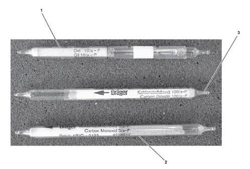
38 (2) Follow the Startup procedures. (3) Perform all During Operation PMCS. (4) Perform all After Operation PMCS. (5) Inspect the E-BAC/SS latches to ensure that they are present and not bent, broken, or damaged. (6) If the cover cannot be secured, the E-BAC/SS is not ready/available. WARNING Diesel engines and various other pieces of equipment are excessively loud. Hearing protection must be worn at all times while operating engines, working in the engine room while the engines are running, and operating other high noise producing equipment. Serious hearing loss or deafness could result if this equipment is operated without proper hearing protection. Prior to using Drager tubes, check the expiration date on the Drager tube box to ensure that the Drager tubes have not expired. Refer to table 6-1 for the authorized Drager tube part numbers. Using expired Drager tubes may produce inaccurate and unacceptable readings of the water vapor, oil, carbon monoxide, and carbon dioxide in the high-pressure air to be stored in the SCBA cylinder. Failure to comply with this warning may result in severe personal injury or death. Before discharging the SCBA cylinder, ensure all personnel are clear of the area to avoid injury from flying debris. Announce to the area that the SCBA cylinder will be bled down to notify personnel nearby. Proper protective equipment must be worn to prevent flying debris from causing severe personal injury. Failure to comply with this warning may result in severe personal injury or death. b. Perform a quarterly air sample test on the E-BAC/SS. (1) Gather the following equipment: (a) Detector Kit, Gas (PN ) (b) Detector, Gas (Carbon Monoxide) (PN ) (c) Detector Tube (Oil) (PN ) (d) Detector Tube (Water Vapor) (PN ) (e) Measuring Tube, Gas Analyzer (Carbon Dioxide) (PN ) (f) Detector, Gas (PN ORION 1111C0P330C1240) (2) Connect a full SCBA cylinder (item 1) to the E-BAC/SS fill hose assembly (item 2). (Figure 551-8ST-1004_28) Page 38
 Open (CCW) the bleed valve (item 4) on the fill hose assembly.")
39 Figure 551-8ST-1004_28 SCBA Cylinder and Fill Hose Assembly (3) Discharge the SCBA cylinder by slowly turning the handwheel (item 3) on the SCBA cylinder to the fully (CCW) open position. (4) Open (CCW) the bleed valve (item 4) on the fill hose assembly. (item 2) (5) Wipe the condensate from the cylinder valve threads with a lint-free rag, AFTER the SCBA cylinder is completely discharged, as indicated by a pressure gauge displaying zero. (item 5) (6) Fill the SCBA cylinder to 4500 PSI. (7) Remove the E-BAC/SS fill hose assembly from the SCBA cylinder. (8) Install the air test kit adapter (item 1), reducer (item 2), and measuring device (item 3) on the SCBA cylinder (item 4). All connections should be hand tight only. (Figure 551-8ST-1004_29) Page 39
40 Figure 551-8ST-1004_29 (SCBA Cylinder, Adapter, and Measuring Device) (9) Open the SCBA cylinder valve (item 5) slowly and allow air from the SCBA cylinder to flush through the measuring device for at least three minutes. WARNING Corrosive mist escapes from the outlet end of some Drager test tubes during measurements. Proper personal protective gear must be worn. Avoid direct skin contact with the outlet ends of the Drager test tubes and tube holders during and after measurements. Rinse the outlet end of each tube holder and the accuro pump thoroughly in a pail of fresh water after completion of measurements to remove contaminants. Failure to comply with this warning may cause personal injury or death. Internal reagent in the oil Drager test tube contains concentrated sulfuric acid. Exercise caution when handling oil Drager test tubes. Do not allow contents to come into contact with exposed skin. Wear rubber gloves and goggles when fracturing and handling oil Drager test tubes. Failure to comply with this warning may result in personal injury or death. (10) Close the SCBA cylinder valve. (11) Score and break off the tips carefully on both (551-8ST-1004_30, item 1) on both ends of one oil, one carbon monoxide (CO) (551-8ST-1004_31, item 2), and one carbon dioxide (CO2) (551-8ST-1004_32, item 3) Drager test tube using the tube opener. Page 40

41 Figure 551-8ST-1004_30 (Drager Test Tube Tip) Page 41

 Insert each Drager test tube into the tube holder of the measuring device specifically marked for that Drager test tube.")
42 Figure 551-8ST-1004_31 (Drager Test Tubes) WARNING Chemicals in the water vapor Drager test tube are extremely sensitive to moisture and humidity. The water vapor Drager test tube and the tube holder must be kept free from moisture during handling and use. Do not OPEN the water vapor Drager test tube until just prior to measurement. Failure to comply with this warning may produce false or incorrect readings for water vapor, which may cause severe personal injury or death. (12) Insert each Drager test tube into the tube holder of the measuring device specifically marked for that Drager test tube. Ensure that the flow arrow on the Drager test tube is pointed away from the measuring device. (13) Score and break off the outlet end (item 1) of the water vapor Drager test tube (item 2) using the tube opener. (Figure 551-8ST-1004_32) Figure 551-8ST-1004_32 (Tube Opener) (14) Score the inlet end (item 3) of the water vapor Drager test tube (item 2) using the tube opener but do not break off the tip. (Figure 551-8ST-1004_33) Page 42
43 Figure 551-8ST-1004_33 (Water Vapor Drager Test Tube) (15) Insert the outlet end (item 1) of the water vapor Drager test tube into the outlet end (lower end) (Figure 551-8ST-1004_34, item 1) of the tube holder (Figure 551-8ST-1004_34, item 2) specifically marked for it. Position the water vapor Drager test tube (Figure 551-8ST-1004_34, item 3) so that the 10 minutes scale is clearly visible when fully installed in the tube holder. Figure 551-8ST-1004_34 Water Vapor Drager Test Tube and Tube Holder (32) Remove the adapter (item 7) from the SCBA cylinder (item 8). (33) Rinse the outlet end of each tube holder (item 9) using a bucket with clean freshwater. Allow the freshwater to cycle through the hand pump several times with the discharge aimed at the bucket. (34) Dry all air test components thoroughly prior to stowage. (35) Record the results of the breathing air test in DA Form 4993 Harbor Boat Engine Department Log for Class A and C-1 Vessels, DA Form 4640 Harbor Boat Deck Department Log for Class A &B Vessels and/or using the Breathing Air Quality log sheet. Refer to Figure 551-8ST-1004_40. Page 43
44 Figure 551-8ST-1004_40 (Breathing Air Quality Report) (16) Break off the inlet end (item 3) of the water vapor Drager test tube (item 2) using the tube opener and immediately insert the inlet end of the water vapor Drager test tube into the tube holder. (17) Slowly OPEN the SCBA cylinder valve (item 4) and start the electronic timer. Note: The oil, carbon monoxide (CO), and carbon dioxide (CO2) Drager test tubes are calibrated for an exposure time of five minutes. (18) Remove the oil (item 1), carbon monoxide (CO) (item 2), and carbon dioxide (CO2) (item 3) Drager test tubes from the tube holder (item 4) after five minutes of exposure. (Figure 551-8ST-1004_35) Page 44
45 Figure 551-8ST-1004_35 (Removal of Drager Test Tubes from the Tube Holder) WARNING If an air sample fails to meet the acceptance criteria for breathing air tests as indicated in table 6-2, the air source (E-BAC/SS) must be tagged out of service. The air source shall not be used for breathing air until resampling/analysis of the air source indicates conformance with the acceptance criteria listed in table 6-2. The requirements stated in table 6-2 meet or exceed the Grade D air requirements as defined by the Compressed Gas Association (ANSI/CGA G-7.1) standard. Failure to comply with this warning may result in severe personal injury or death. (19) Continue water vapor (item 5) testing for 10 minutes. (20) Identify and record the measurements for carbon monoxide (CO) and carbon dioxide (CO2) in accordance with the scale provided on each respective Drager test tube. WARNING Internal reagent in the oil Drager test tube contains concentrated sulfuric acid. Exercise caution when handling oil Drager test tubes. Do not allow contents to come into contact with exposed skin. Wear rubber gloves and goggles when fracturing and handling oil Drager test tubes. Failure to comply with this warning may result in personal injury or death. (21) Compare the measurement of each Drager test tube for acceptance criteria using Figure 551-8ST-1004_36. Page 45
46 Figure 551-8ST-1004_36. (Acceptance Criteria for Breathing Air Test) WARNING If an air sample fails to meet the acceptance criteria for breathing air tests as indicated in Figure 551-8ST- 1004_34, the air source (E-BAC/SS) must be tagged out of service. The air source shall not be used for breathing air until re-sampling/analysis of the air source indicates conformance with the acceptance criteria listed in Figure 551-8ST-1004_34. The requirements stated in Figure 551-8ST-1004_34 meet or exceed the Grade D air requirements as defined by the Compressed Gas Association (ANSI/CGA G-7.1) standard. Failure to comply with this warning may result in severe personal injury or death. (22) Bend the oil Drager test tube sharply at the indicated point (between the double dots) on the oil Drager test tube, so that the outer glass tube and the interna1 reagent ampoule break. Allow the ampoule fluid to flow into the indicating layer of the oil Drager test tube. Use the Drager Accuro pump (item 1) to apply light suction to the outlet side of the oil Drager test tube (item 2) until approximately 10 mm (3/8 inch) of the indicating layer is covered with the ampoule fluid. (Figure 551-8ST-1004_37) Page 46

47 Figure 551-8ST-1004_37 (Draeger Accuro Pump) (23) Wait one minute before reading the results. If no color change occurs, the concentration of oil in the air sample is less than 5 mg/m3 and is acceptable. Refer to Figure 551-8ST-1004_36. Any color change indicates an unacceptable reading. Note: When reading the results of the water vapor Drager test tube a reddish brown color is an indication of water and shall be used to determine the level of moisture within the air sample. There are several color changes that occur during the chemical reaction of the test before turning reddish brown. Read only the reddish brown level. (24) After 10 minutes on the electronic timer, remove the water vapor Drager test tube from the tube holder and read and record the measurement. A color change to reddish brown is an indication of moisture. (25) Read the level of moisture on the 10-minute scale of the water vapor Drager test tube. The acceptance criteria for water vapor is less than or equal to 20 mg/ m3. Refer to Figure 551-8ST-1004_36. (26) To perform the oxygen measurement, insert the straight barbed fitting (item 1) of the Drager breathing air test kit into the carbon monoxide (CO) tube holder (item 2) Figure 551-8ST-1004_38 Page 47
48 Figure 551-8ST-1004_38 (Barbed Fitting and Tube Holder) (27) Ensure that the SCBA cylinder valve (item 3) is open and sample air is flowing from the measuring device (item 4). (28) Remove the slip on adapter (item 1) from the four-gas analyzer (figure 6-item 2). (Figure 551-8ST-1004_39) Page 48
49 (29) Install a short length of sample tubing (item 3) on the barbed fitting (item 4) and the slip on adapter. WARNING If an air sample fails to meet the acceptance criteria for breathing air tests as indicated in Figure 551-8ST- 1004_34, the air source (E-BAC/SS) must be tagged out of service. The air source shall not be used for breathing air until re-sampling/analysis of the air source indicates conformance with the acceptance criteria listed in Figure 551-8ST-1004_34. The requirements stated in Figure 551-8ST-1004_34meet or exceed the Grade D air requirements as defined by the Compressed Gas Association (ANSI/CGA G-7.1) standard. Failure to comply with this warning may result in severe personal injury or death. (30) Refer to your vessel's four-gas analyzer's Original Equipment Manufacturer's (OEM) instructions and perform an oxygen test. (31) Close the SCBA cylinder valve (item 5) and remove the sample tubing from the barbed fitting in the measuring device (item 6), and the slip on adapter. c. Perform semi-annual testing and checking of the diesel engine assembly. Page 49
 Figure 551-8ST-1004_41 (Diesel Engine Air Filter Housing) (b) Remove the cover from the air filter housing. (c) Wipe the cover with a clean lint free rag.")
50 (1) Lock out and tag out (FM ) (supersedes FM ). (2) Change the diesel engine air filter: (a) Remove the wing nut from the air filter cover. (Figure 551-8ST-1004_41) Figure 551-8ST-1004_41 (Diesel Engine Air Filter Housing) (b) Remove the cover from the air filter housing. (c) Wipe the cover with a clean lint free rag. (d) Remove the air filter from the housing and discard. (e) Wipe out the interior of the housing using a clean lint free rag. (f) Install a new air filter in the housing. (g) Install the cover on the housing. (h) Install the wing nut on the cover. (i) Remove the lockouts and tagouts (FM ) (supersedes FM ). d. Service the P1 purification chamber assembly and CO/ H2O indicator semi-annually. Note: The CO/H2O indicator element and the P1 purification cartridge shall be changed at the same time. The CO/H2O indicator element and the P1 purification cartridge shall be changed semiannually or if any of the following conditions exist: (Figure 551-8ST-1004_42) Page 50
 Lock out, tag out (FM 4-01.")
51 Figure 551-8ST-1004_42 (Indicator Table) (1) After replacing the CO/H2O indicator element and the P1 purification cartridge, a breathing air quality test shall be performed. (2) Lock out, tag out (FM ) (supersedes FM ), and perform the following steps to change the cartridge and the CO/H2O indicator: (Figure 551-8ST-1004_43) Page 51
 Slowly OPEN the P1 bleed valve located below the CO/H2O indicator to bleed the pressure from the (b) Install the P1 purification cap wrench on the P1 purification chamber cap.")
52 Figure 551-8ST-1004_43 (P1 Purification Chamber Assembly and CO/ H2O Indicator) system. (a) Slowly OPEN the P1 bleed valve located below the CO/H2O indicator to bleed the pressure from the (b) Install the P1 purification cap wrench on the P1 purification chamber cap. (c) Using the wrench, remove the cap from the P1 purification chamber. (d) Remove the P1 purification cartridge from the chamber. Discard the cartridge. (e) Using a lint free rag, wipe out the inside of the chamber. CAUTION Do not touch the new P1 purification cartridge with bare skin. Oil from the skin will damage the equipment and affect system performance. Failure to comply with this caution may result in equipment damage. (f) Inspect the new cartridge bag to ensure that the vacuum seal is still intact. If the vacuum seal has been broken discard and use one that has not had its vacuum seal broken. (g) Carefully OPEN the new cartridge vacuum-sealed bag at both ends. Page 52
53 (h) Remove the protective seal and cap from the top and bottom of the new cartridge. (i) Discard the protective seal and cap. (j) Using a clean lint free rag, install the new cartridge in the chamber. (k) Snap the new cartridge into place by pushing it straight down with slight pressure. (l) Install the cap on the chamber hand tight. (m) Tighten the cap snugly using the cap wrench. Note: The CO/H2O indicator has a one-year shelf life. Verify that the new CO/H2O indicator is less than six months old prior to installing it in the CO/H2O indicator housing. (n) Remove the CO/H2O indicator housing cap by turning it counterclockwise. (o) Remove the spring from the indicator housing. Do not discard. (p) Remove the CO/H2O indicator button and strip from the indicator housing. (q) Discard the indicator button and strip. (r) Remove the tape backing from the new indicator strip. button. (s) Discard the tape backing. Note: The active face of the CO/H2O indicator button is the rough or granular side of the CO/H2O indicator (t) Install the new indicator strip centered on the active face of the new indicator button. (u) Install the new indicator button in the indicator housing so that the new indicator strip will appear centered in the window of the indicator housing with both sides of the new indicator button visible on either side of the indicator strip. (v) Install the spring in the indicator housing. (w) Install the indicator housing cap and tighten it hand tight by turning it clockwise. (x) Close the P1 bleed valve located below the CO/H2O indicator. (y) Remove the lockouts and tagouts (FM ) (supersedes FM ). (z) Perform the Before PMCS checks and the Startup procedure IAW paragraph Note: Knowledge the Soldier must have: K-1: The Soldier should know how to startup the E-BAC/SS. K-2: The Soldier should know how to stop the E-BAC/SS. (aa) Pressurize the P1 purification chamber and check for leaks. (ab) Operate the E-BAC/SS IAW paragraph with the fill hose assemblies open to the atmosphere for a minimum of 15 minutes to purge the system. (ac) Perform an air sample test. Page 53

54 (ad) Stop the E-BAC/SS. CAUTION Cleaning and inspecting the fuel filter element must be performed only when the E-BAC/SS is cool to prevent the diesel engine fuel source from igniting should it drip or spill onto the E-BAC/SS components. Failure to comply with this caution may result in damage to the equipment. e. Service and inspect the diesel engine assembly annually. (Figure 551-8ST-1004_44) Figure 551-8ST-1004_44 (Diesel Engine Assembly) (1) Ensure the fuel valve for the diesel engine is in the off position. filter: (2) Lock out, tag out ( see FM ), and perform the following steps to clean and inspect the engine fuel Page 54
55 WARNING Fuel oil and other petroleum products are highly volatile in extreme heat. To minimize the possibility of an explosion, wipe up all spills at once, and ensure that fuel lines and valves are not leaking. Failure to comply with this warning may result in serious injury or death to personnel. Always wear chemical protective gloves and goggles when handling diesel fuel. In case of contact with the skin, remove contaminated clothing and wash with soap and water. In case of large-scale skin contamination, get medical attention immediately. In case of eye contact, flush the eyes with fresh water for at least 15 minutes and get medical attention immediately. In case of inhalation, remove to fresh air and give oxygen or perform rescue breathing as the situation dictates. In case of ingestion, give two glasses (16 oz.) of water (if the victim is conscious and able to swallow), and get immediate medical attention. Do not induce vomiting; lung damage may result from vomiting after ingestion. If vomiting occurs, give fluids again. Diesel fuel may cause skin irritation upon contact with the skin, eye irritation upon contact with the eyes, and illness if ingested. Failure to comply with this warning may result in serious injury or death to personnel. (a) Place a suitable drain pan under the diesel fuel tank drain plug. (b) Remove the drain plug from the bottom of the fuel tank and drain the fuel into the drain pan. (c) Install the drain plug in the bottom of the fuel tank. (d) Remove the two nuts and washers from the fuel filter studs. (e) Remove the fuel valve from the diesel engine fuel filter element studs. (f) Remove the gasket from the engine fuel filter studs. (g) Remove the engine fuel filter from the fuel tank. (h) Inspect the engine fuel filter element for damage or deterioration. Page 55
56 WARNING Fuel oil and other petroleum products are highly volatile in extreme heat. To minimize the possibility of an explosion, wipe up all spills at once, and ensure that fuel lines and valves are not leaking. Failure to comply with this warning may result in serious injury or death to personnel. Always wear chemical protective gloves and goggles when handling diesel fuel. In case of contact with the skin, remove contaminated clothing and wash with soap and water. In case of large-scale skin contamination, get medical attention immediately. In case of eye contact, flush the eyes with fresh water for at least 15minutes and get medical attention immediately. In case of inhalation, remove to fresh air and give oxygen or perform rescue breathing as the situation dictates. In case of ingestion, give two glasses (16 oz.) of water (if the victim is conscious and able to swallow), and get immediate medical attention. Do not induce vomiting; lung damage may result from vomiting after ingestion. If vomiting occurs, give fluids again. Diesel fuel may cause skin irritation upon contact with the skin, eye irritation upon contact with the eyes, and illness if ingested. Failure to comply with this warning may result in serious injury or death to personnel. (i) Replace with a new filter element, if required. (j) If a new filter is not required, wash the filter thoroughly with clean diesel fuel. (k) Install the filter in the fuel tank. (l) Install the gasket on the fuel filter studs. (m) Install the fuel valve on the fuel filter studs. WARNING Diesel fuel may cause skin irritation upon contact with the skin, eye irritation upon contact with the eyes, and illness if ingested. Always wear chemical protective gloves and goggles when handling diesel fuel. In case of contact with the skin, remove contaminated clothing and wash with soap and water. In case of large-scale skin contamination, get medical attention immediately. In case of eye contact, flush the eyes with fresh water for at least 15 minutes and get medical attention immediately. In case of inhalation, remove to fresh air and give oxygen or perform rescue breathing as the situation dictates. In case of ingestion, give two glasses (16 oz.) of water (if the victim is conscious and able to swallow), and get immediate medical attention. Do not induce vomiting; lung damage may result from vomiting after ingestion. If vomiting occurs, give fluids again. Do not smoke or permit open flame in the area of the E-BAC/SS while refueling. Fuel may ignite, causing serious injury or death to personnel. Failure to comply with this warning may result in serious injury or death to personnel. (n) Install the two nuts and washers on the filter studs. Page 56
 Figure 551-8ST-1004_45 (Diesel Engine Assembly) (1) Perform the Before Operations PMCS.")
57 (o) Fill the diesel fuel tank with the proper diesel fuel. (p) Remove the lockouts and tagouts (q) Operate the E-BAC/SS and check for leaks. (r) Return the E-BAC/SS to the desired readiness condition. f. Service and test the diesel engine assembly annually or at 500 hours. (Figure 551-8ST-1004_45) Figure 551-8ST-1004_45 (Diesel Engine Assembly) (1) Perform the Before Operations PMCS. Operate the E-BAC/SS for 10 minutes. (2) Lock out, tag out. (3) Perform the following steps to change the diesel engine oil and replace the lube oil strainer: WARNING Do not allow diesel engine crankcase oil to come in contact with unprotected skin or eyes. Prolonged skin contact can cause illness or injury. Eye contact can cause serious injury. Always wear chemical protective gloves and goggles when handling hydraulic fluid, compressor crankcase oil, engine oil, and cleaning solvents. Failure to follow these precautions can result in illness, serious injury, or death. (a) Place a drain pan under the engine oil drain hose. Page 57
58 (b) Remove the plug from the drain hose and allow the oil to drain into the pan. (c) Using a lint free rag, clean the end of the drain hose. (d) Install the plug in the drain hose. (e) Inspect the drained oil for metallic particles. (f) Notify the maintenance supervisor if any metallic particles are found. Note: The shims and upper rubber vibration absorber to the diesel engine mounting plate must be removed prior to removing the oil strainer. (g) Remove the nut and bolt from the vibration eliminator assembly. (h) Remove the two vibration shims and upper vibration eliminator from the mounting plate. (i) Remove the retaining bolt from the oil strainer cap. (j) Remove the oil strainer from the engine by turning it counterclockwise. (k) Remove the oil strainer and o-ring from the cap. Discard the oil strainer and o-ring. (l) Install a new o-ring and oil strainer on the filter cap. (m) Install the cap in the engine. (n) Install the two vibration shims and the upper vibration eliminator on the engine mounting plate. (o) Install the nut and bolt in the vibration eliminator assembly. (p) Remove the engine dipstick. (q) Wipe the dipstick clean. (r) Fill the engine crankcase with 1.16 quarts of oil. (Figure 551-8ST-1004_15) (s) Install the dipstick in the crankcase. (t) Remove the dipstick and verify that the oil level is at the maximum mark on the dipstick. (u) Add or remove oil as required to bring the oil level in the engine to the maximum mark on the dipstick. (v) Remove the lockouts and tagouts. (w) Operate the E-BAC/SS and check for leaks. (x) Return the E-BAC/SS to the desired readiness condition. g. Service and test the air compressor unit assembly annually or at 500 hours. (1) Perform the Before Operations PMCS. Operate the E-BAC/SS IAW paragraph for five minutes. Page 58
 (4) Perform the following steps to change the compressor crankcase oil: WARNING Do not allow compressor crankcase oil to come in contact with unprotected skin or eyes.")
59 (2) Stop the E-BAC/SS. (3) Lock out, tag out (FM ) (4) Perform the following steps to change the compressor crankcase oil: WARNING Do not allow compressor crankcase oil to come in contact with unprotected skin or eyes. Prolonged skin contact can cause illness or injury. Eye contact can cause serious injury. Always wear chemical protective gloves and goggles when handling hydraulic fluid, compressor crankcase oil, engine oil, and cleaning solvents. Failure to follow these precautions can result in illness, serious injury, or death. (a) Place a drain pan under the compressor crankcase oil drain hose. (b) Remove the drain plug from the drain hose and allow the oil to drain into the pan. (c) Inspect the drained compressor crankcase oil for metallic particles. (Figure 551-8ST-1004_46) Figure 551-8ST-1004_46 (Compressor Crankcase) (d) Notify the maintenance supervisor if any metallic particles are found. (e) Using a lint free rag, clean the end of the drain hose. Page 59
60 (f) Install the drain plug in the oil drain hose. (g) Fill the compressor crankcase with approximately 1.5 quarts of compressor oil. Refer to figure 551-8ST for the proper oil. (h) Check the oil level when filling. The crankcase oil level should be at the maximum mark on the dipstick when the compressor crankcase is full. (i) Remove the lockouts and tagouts. (j) Operate the E-BAC/SS and check for leaks. (k) Return the E-BAC/SS to the desired readiness condition. h. Service and inspect the air intake filter assembly annually (1) Lock out, tag out. (2) Perform the following steps to clean or change the compressor intake air filter: (3) Remove the compressor air filter cover from the air filter housing by turning it counterclockwise. (Figure 551-8ST-1004_47) Figure 551-8ST-1004_47 (Air Intake Filter Assembly) Page 60
61 (4) Remove the spring and o-ring from the cover. (5) Discard the o-ring. Note: The compressor air filter can be cleaned and rotated three times before it is required to be replaced. When cleaning the compressor air filter, mark it so that it is obvious how many times it has been cleaned. Always rotate the compressor air filter clockwise. (6) Mark the air filter at the 12 o'clock position for reference during installation. (7) Remove the air filter and o-ring from the filter housing. (8) Discard the o-ring. (9) Clean the filter with a brush and inspect it for clogging. If the filter is clogged, replace it. (10) Install the filter and a new o-ring in the housing (rotating it 90 degrees from the position marked in step c if cleaned). (11) Install the spring and new o-ring in the air filter cover. (12) Install the filter cover on the housing. (13) Remove the lockouts and tagouts. (14) Operate the E-BAC/SS IAW paragraph and check for proper operation. (15) Return the E-BAC/SS to the desired readiness condition. (Figure 551-8ST_1004_48) Page 61
 Note: Lock out, tag out and perform the following steps to clean the intermediate separator assembly: Figure 551-8ST_1004_49 (Intermediate Separator Assembly) (1) Fill two")
62 Figure 551-8ST_1004_48 (Air Filter Intake Assembly) i. Service and inspection of the intermediate separator assembly annually or at 1,000 hours. (Figure 551-8ST- 1004_49) Note: Lock out, tag out and perform the following steps to clean the intermediate separator assembly: Figure 551-8ST_1004_49 (Intermediate Separator Assembly) (1) Fill two one-gallon buckets with warm freshwater. (2) Add one tablespoon of general-purpose detergent to one of the buckets and mix thoroughly. The second bucket of warm water will be used for rinse water. (3) Open the intermediate separator condensate drain to allow any pressure to be vented. (4) Remove the third stage cylinder tubing from the top of the separator head. CAUTION Do not use a pipe wrench, chain strap wrench, or vise on the threaded collar or housing of the intermediate separator. Failure to comply with this caution will result in damage to the equipment. NOTE: If the threaded collar cannot be loosened by hand, use a nylon strap wrench. (5) Remove the second stage intercooler tubing from the side of the separator head. Page 62
63 (6) Remove the threaded collar from the intermediate separator housing. (7) Remove the intermediate separator head from the housing. (8) Remove the center screw from the separator head. (9) Remove the metal filter, the baffle cone, and the vortex plate from the center screw. (10) Remove the o-ring from the separator head. Discard the o-ring. WARNING Always wear protective goggles and gloves when using compressed air to dry clean parts. Direct the airflow away from body parts and other personnel in the area. Drying cleaned parts with the airflow directed at body parts or other personnel may cause contaminants to be injected into the body, which may cause severe illness or death. (11) Clean the metal filter thoroughly in the bucket with the general-purpose detergent and rinse thoroughly in the bucket of freshwater. (12) Dry the metal filter with low pressure air. (13) Install the metal filter on the center screw. (14) Install the baffle cone on the center screw. (15) Install the vortex plate on the center screw. (16) Install the center screw in the separator head. (17) Install the o-ring on the separator head. CAUTION Do not use a pipe wrench, chain strap wrench, or vise on the threaded collar or housing of the intermediate separator. Failure to comply with this caution will result in damage to the equipment. (18) Install the separator head on the housing. (19) Install the threaded collar on the separator housing. (20) Install the intercooler in the side of the separator head. (21) Install the cylinder tubing in the top of the separator head. (22) Close the intermediate separator condensate drain. (23) Remove the lockouts and tagouts IAW FM Page 63
 Figure 551-8ST-1004_50 (Pike Head Fire Axe) a. Axes should be sharpened, cleaned, or repaired as necessary. b. The blade and pike ends should be kept sharp and free of burrs.")
64 (24) Operate the E-BAC/SS. (25) Perform an air sample test. (26) Return the E-BAC/SS to the desired readiness condition. 8. Inspect fire axes. Inspect fire axes periodically (Figure 551-8ST-1004_50) Figure 551-8ST-1004_50 (Pike Head Fire Axe) a. Axes should be sharpened, cleaned, or repaired as necessary. b. The blade and pike ends should be kept sharp and free of burrs. c. The handle should be tight in the axe head and free of splits and splinters. d. An occasional light oiling will keep the head from rusting. Page 64
Checklist for care of Respirators
 Checklist for care of Respirators Inspect the respirator before and after each use and during cleaning. Inspect equipment designated for "emergency use" at least monthly, and after each use. Replace all
MMR Air Mask With. with Quick-Connect Hose
 MMR Air Mask With with Quick-Connect Hose Upgrade Kits P/N 10025120 Slide to Connect P/N 10050038 Slide to Connect w/ Solid Cover P/N 10038666 Push To Connect P/N 10050037 Push To Connect w/ Solid Cover
Product Information News
 Product Information News MMR SECOND STAGE REGULATOR VALVE CORE MSA has changed its recommended rebuilding of the MMR Second Stage Regulator s bypass sleeve assembly during the annual inspection. Based
Summary Report for Individual Task L-2049 Maintain Firefighting Equipment Status: Approved
 Report Date: 30 Jun 2014 Summary Report for Individual Task 551-88L-2049 Maintain Firefighting Equipment Status: Approved Distribution Restriction: Approved for public release; distribution is unlimited.
ESCONDIDO FIRE DEPARTMENT TRAINING MANUAL ENGINE MODULE SCBA PAGE 1 OF 14 Maintenance Revised
 SCBA 10-07-16 PAGE 1 OF 14 The California Occupational Safety and Health Administration requires that: Respirators shall be regularly cleaned after each use or more often if necessary. Those used by more
Respiratory Protection. Program
 Respiratory Protection Program Respiratory Protection Program Table of Contents A. General B. Selection of Respirators C. Medical Screening D. Fit Testing E. Respirator Use Instructions F. Respirator Inspection
Combination Breathing Apparatus
 and Combination Breathing Apparatus ULTRAVUE FACEPIECE TAL 502 (L) Rev. 0 MSA 2005 Prnt. Spec. 10000005389 (I) Mat. 10064385 Doc. 10064385 ULTRAVUE FACEPIECE COMPONENTS Item Part No. Description 800509
ESCONDIDO FIRE DEPT TRAINING MANUAL Section Engine Module Page 1 of 11 Specifications and Overview Revised
 Engine Module Page 1 of 11 The City of Escondido Fire Department has developed and implemented a comprehensive respiratory program to ensure compliance with Local, State, and Federal laws concerning several
INSTRUCTION MANUAL EBA-75 CLOSED-CIRCUIT ESCAPE RESPIRATOR (CCER) CAPACITY 3
 CAPACITY 3") INSTRUCTION MANUAL FOR THE EBA-75 CLOSED-CIRCUIT ESCAPE RESPIRATOR (CCER) CAPACITY 3 Manual Number: NH24053 Revision: A, ECN 3590 December 14, 2015 Page 1 of 13 CONTENTS PAGE INTRODUCTION... 3 GENERAL
INSTRUCTION MANUAL FOR THE EBA-75 CLOSED-CIRCUIT ESCAPE RESPIRATOR (CCER) CAPACITY 3 Manual Number: NH24053 Revision: A, ECN 3590 December 14, 2015 Page 1 of 13 CONTENTS PAGE INTRODUCTION... 3 GENERAL
TOOL BOX 031- SERVICE OF CARTRIDGE EXTINGUISHERS
 A. SANS1475.1:2012 3.8 gas cartridge Cylinder that is attached externally to the extinguisher cylinder and that contains either compressed or liquefied gas. 3.14.1 External cartridge operated type Extinguisher
M7XT Parts List PARTS LIST. TAL 1504 (L) Rev. 2 MSA 2015 Prnt. Spec (I) Mat Doc
 Rev. 2 MSA 2015 Prnt. Spec (I) Mat Doc") M7XT Parts List PARTS LIST TAL 1504 (L) Rev. 2 MSA 2015 Prnt. Spec. 10000005389(I) Mat. 10146000 Doc. 10146000 M7XT PARTS LIST FireHawk M7XT Carrier and Harness Assembly Replacement Kits...3 Exploded View...4
M7XT Parts List PARTS LIST TAL 1504 (L) Rev. 2 MSA 2015 Prnt. Spec. 10000005389(I) Mat. 10146000 Doc. 10146000 M7XT PARTS LIST FireHawk M7XT Carrier and Harness Assembly Replacement Kits...3 Exploded View...4
BioPak 240 Revolution
 BioPak 240 R Instructions Circle the correct letter or answer that represents the BEST answer. If you make a correction make sure all erasures are complete. You have 30 minutes to complete this quiz. Please
IMPORTANT SAFETY INSTRUCTIONS READ AND FOLLOW ALL INSTRUCTIONS SAVE THESE INSTRUCTIONS
 Warrior D.E. Filter Operating Procedures IMPORTANT SAFETY INSTRUCTIONS READ AND FOLLOW ALL INSTRUCTIONS SAVE THESE INSTRUCTIONS Table of Contents SECTION I. FILTER INSTALLATION... 1 SECTION II. FILTER
INSTALLATION. and INSTRUCTION MANUAL. for QUALITY AIR BREATHING SYSTEMS. Model 50 Systems Outfitted with ABM-725 Monitor C O M P A N Y
 INSTALLATION and INSTRUCTION MANUAL for QUALITY AIR BREATHING SYSTEMS Model 50 Systems Outfitted with ABM-725 Monitor M A R T E C H S E R V I C E S C O M P A N Y OFFICE: (507) 843-4700 P.O. BOX 7079 Toll
PremAire INSTRUCTIONS FOR DUAL-SUPPLY MODE OF OPERATION
 DUAL SUPPLY REGULATOR ESCAPE CYLINDER VORTEX MAIN INLET PremAire INSTRUCTIONS FOR DUAL-SUPPLY MODE OF OPERATION WARNING This manual must be read carefully by all persons who have who will have the responsibility
INSTRUCTION MANUAL FOR EBA MINUTE SELF-CONTAINED SELF RESCUER (SCSR) Manual Number: NH13747 Revision: A, ECN 2384 September 7, 2001
 Manual Number: NH13747 Revision: A, ECN 2384 September 7, 2001") INSTRUCTION MANUAL FOR EBA 6.5 60 MINUTE SELF-CONTAINED SELF RESCUER (SCSR) Manual Number: NH13747 Revision: A, ECN 2384 September 7, 2001 Page 1 of 20 CONTENTS PAGE INTRODUCTION 3 GENERAL INFORMATION..3
INSTRUCTION MANUAL FOR EBA 6.5 60 MINUTE SELF-CONTAINED SELF RESCUER (SCSR) Manual Number: NH13747 Revision: A, ECN 2384 September 7, 2001 Page 1 of 20 CONTENTS PAGE INTRODUCTION 3 GENERAL INFORMATION..3
III. Identify the initial installation requirements for standpipe systems
 Design Basic Design Requirements 1. Must provide 500 GPM at 65 PSI to the highest most remote standpipe riser outlet. 2. 250 GPM for each additional standpipe total not to exceed 2500 GPM III. Identify
BioPak 240 Revolution
 BioPak 240 R Instructions Circle the correct letter or answer that represents the BEST answer. If you make a correction make sure all erasures are complete. Each question is worth 2.5 points for a total
Fit Testing. C50 APR New Equipment Training Module March 2010 Rev01
 Fit Testing Once all three steps are complete, the mask must be fit tested. This is done using the TSI Portacount Test System Before either of the tests begin, the mask must be set up properly. Fit and
FOR INSTALLING CO 2 BLENDER KIT (P/N IN BEER SYSTEM
 IMI CORNELIUS INC One Cornelius Place Anoka, MN 55303-623 Telephone (800) 238-3600 Facsimile (612) 22-326 INSTALLATION INSTRUCTIONS FOR INSTALLING CO 2 BLENDER KIT (P/N 111612000 IN BEER SYSTEM SECONDARY
DREW UNIVERSITY RESPIRATORY PROTECTION PROGRAM DRAFT 06/11
 PURPOSE This policy provides requirements on the selection, use, care, and maintenance of respiratory protection. Also included is information and guidelines on training, medical evaluations, recordkeeping
KIRBY MORGAN DEEP SEA DIVING HELMETS ALL MODELS HELMET AND EMERGENCY GAS SYSTEM DAILY SET-UP AND FUNCTIONAL CHECKLIST APPENDIX A2.
 KIRBY MORGAN DEEP SEA DIVING HELMETS ALL MODELS HELMET AND EMERGENCY GAS SYSTEM DAILY SET-UP AND FUNCTIONAL CHECKLIST APPENDIX A2.3 01-25-17 THIS DAILY SET-UP AND FUNCTIONAL CHECKLIST SHOULD BE COMPLETED
GETZ EQUIPMENT INNOVATORS RECOVERY SYSTEM CLEAN AGENT FE-36 / HALOTRON 1 PART NO. 4G59751 OPERATIONS MANUAL
 GETZ EQUIPMENT INNOVATORS CLEAN AGENT FE-36 / HALOTRON 1 PART NO. 4G59751 OPERATIONS MANUAL GETZ EQUIPMENT INNOVATORS PEKIN, ILLINOIS, U.S.A. PHONE: (888) 747-4389 FAX: (309) 495-0625 Limited Warranty
Model: 43T. Bermad Pressure Relief Valve
 Model: 43T Bermad Pressure Relief Valve Installation Operation Maintenance Manual () Rev.C1_01.08.17 Page 1 of 10 Safety First BERMAD believes that the safety of personnel working with and around our equipment
Water Mist Systems Inspection, Testing, and Maintenance of Water Mist Systems
 Water Mist Systems Inspection, Testing, and Maintenance of Water Mist Systems Name of Property: Address: Phone Number: Inspector: Contract No.: Date: This Report Covers: Monthly Quarterly Annual Other
Half Facepiece Respirator Assembly 5000 Series, Dual Cartridge, Organic Vapor/P95, Disposable
 Half Facepiece Respirator Assembly 5000 Series, Dual Cartridge, Organic Vapor/P95, Disposable User Instructions for 3M Organic Vapor Respirator, P95 Assembly 51P71/52P71/53P71 Important: Keep these User
GREIG FILTERS, INC. OPERATION MANUAL
 GREIG FILTERS, INC. OPERATION MANUAL MODEL DCFH 3P 15/3 100 S4 DOE/222 DUAL CARTRIDGE FILTER HOUSING TABLE OF CONTENTS I. INTRODUCTION II. CARTRIDGE FILTER HOUSING UNIT A. OPERATION B. INSTALLATION C.
Course Firefighter I. Unit II Safety and Orientation
 Course Firefighter I Unit II Safety and Orientation Essential Question Why is proficiency donning and doffing SCBA important for firefighters? TEKS 130.299(c) (2)(C), (10)(B), (11)(A)(C)(E), (14)(A)(B)
Warning: NEVER ALTER TEST EQUIPMENT
 PAGE 1 OF 6 General: Pressure Testing Shop Built Tanks Pressure testing tanks with either positive pressure or vacuum can be a very dangerous exercise. It is important to understand the equipment involved
STATEMENTS OF FACT BENCH BG-4 CONTEST. 1. A positive pressure leak could be caused by a leakage in or at device components.
 STATEMENTS OF FACT BENCH BG-4 CONTEST 1. A positive pressure leak could be caused by a leakage in or at device components. 2. The battery in the Sentinel should be replaced every 6 months. 3. Dow Corning
Phalanx Alpha Phalanx Beta and Ultra Elite
 Phalanx Alpha Phalanx Beta and Ultra Elite riot control agent gas masks instructions parts list NIOSH approved for respiratory protection in atmospheres containing CN and CS and particulates under the
TECHNICAL DATA MAINTENANCE AIR COMPRESSOR MODEL G-1
 Dry 131h 1. DESCRIPTION The Viking Model G-1 Maintenance Air Compressor is an electric motor-driven, aircooled, single-stage, oil-less compressor. The unit is equipped with a check valve and provides a
PremAire INSTRUCTIONS FOR VORTEX TUBE MODE OF OPERATION
 DUAL SUPPLY REGULATOR ESCAPE CYLINDER VORTEX MAIN INLET PremAire INSTRUCTIONS FOR VORTEX TUBE MODE OF OPERATION WARNING THIS MANUAL MUST BE READ CAREFULLY BY ALL PERSONS WHO HAVE OR WILL HAVE THE RESPONSIBILITY
Entry to these spaces must be rigorously controlled to prevent serious injury or death.
 Chapter 6 - Confined Spaces Chapter 6 Confined Spaces Definitions A confined space is defined as any structure that must be entered and that has or may contain dangerous concentrations of hazardous gases
Summary of Accumulators These operating instructions apply to the accumulators listed in the table shown below.
 Page 1 of 15 Summary of Accumulators These operating instructions apply to the accumulators listed in the table shown below. Model Number A25-XXXX-3.6K Series A40-XXXX-3K Series A40X-XXXX-3.6K Series A60-XXXX-3K
A. Evaluation of the written program
 A. Evaluation of the written program Begin your audit with an evaluation of the written respiratory protection program. In addition to the operating procedures describing respirator selection and use in
SCOTT RIT-PAK III Portable air supply
 SCOTT RIT-PAK III Portable air supply Operating and Maintenance instructions For use with a SCOTT air cylinder to supply breathing air to COMPATIBLE SCOTT PRODUCTS This instruction sheet describes the
BMR Low/High Pressure USERS MAINTENANCE INSTRUCTIONS
 BMR Low/High Pressure USERS MAINTENANCE INSTRUCTIONS THIS MANUAL MUST BE READ CAREFULLY BY ALL PERSONS WHO HAVE OR WILL HAVE THE RESPONSIBILITY FOR USING OR SERVICING THE PRODUCT. Like any complex piece
Operating Instructions Model and Hydrostatic Test Pump
 Operating Instructions Model 39300 and 39301 Hydrostatic Test Pump Dimension Weight Pump Style Capacity Pressure Motor Lubrication Control Gauge Inlet Connection Outlet Connection Discharge Hose Hose Ends
KMB 18/28 (BANDMASK) OVERHAUL, MAINTENANCE, AND INSPECTION CHECKLIST APPENDIX A
 OVERHAUL, MAINTENANCE, AND INSPECTION CHECKLIST APPENDIX A") KMB 18/28 (BANDMASK) OVERHAUL, MAINTENANCE, AND INSPECTION CHECKLIST APPENDIX A2.1 01-31-17 THIS INSPECTION AND MAINTENANCE SHOULD BE PERFORMED AT LEAST ANNUALLY AND AS DICTATED BY CONDITION REVEALED DURING
KMB 18/28 (BANDMASK) OVERHAUL, MAINTENANCE, AND INSPECTION CHECKLIST APPENDIX A2.1 01-31-17 THIS INSPECTION AND MAINTENANCE SHOULD BE PERFORMED AT LEAST ANNUALLY AND AS DICTATED BY CONDITION REVEALED DURING
170-CG Feed Unit SPONGE-JET USER MANUAL. Sponge-Jet, Inc. (USA) 14 Patterson Lane Newington, NH
 14 Patterson Lane Newington, NH") SPONGE-JET 170-CG Feed Unit USER MANUAL Sponge-Jet, Inc. (USA) 14 Patterson Lane +1-603-610-7950 Newington, NH 03801 www.spongejet.com AUGUST 2014, Sponge-Jet 170-CG User Manual - REV A / DOC: M-MKTG-002ENG
SPONGE-JET 170-CG Feed Unit USER MANUAL Sponge-Jet, Inc. (USA) 14 Patterson Lane +1-603-610-7950 Newington, NH 03801 www.spongejet.com AUGUST 2014, Sponge-Jet 170-CG User Manual - REV A / DOC: M-MKTG-002ENG
( SC) NOTE: KMDSI strongly recommends that all repairs be performed by trained Personnel.
 NOTE: KMDSI strongly recommends that all repairs be performed by trained Personnel.") KIRBY MORGAN SUPERLITE DEEP SEA DIVING HELMET MODELS 17 A/B, 17C, 17K, & KM 37, KM 47, KM 57, KM 77 & KM 97 MONTHLY INSPECTION AND MAINTENANCE CHECKLIST Appendix A2.2 (10-2-2016 SC) This inspection is
KIRBY MORGAN SUPERLITE DEEP SEA DIVING HELMET MODELS 17 A/B, 17C, 17K, & KM 37, KM 47, KM 57, KM 77 & KM 97 MONTHLY INSPECTION AND MAINTENANCE CHECKLIST Appendix A2.2 (10-2-2016 SC) This inspection is
KMB 18/28 (BANDMASK) MONTHLY MASK INSPECTION APPENDIX A
 MONTHLY MASK INSPECTION APPENDIX A") KMB 18/28 (BANDMASK) MONTHLY MASK INSPECTION APPENDIX A2.2 08-01-17 This inspection is the minimum recommended maintenance and should be performed at least ONCE A MONTH with Mask(s) in continuous use (used
KMB 18/28 (BANDMASK) MONTHLY MASK INSPECTION APPENDIX A2.2 08-01-17 This inspection is the minimum recommended maintenance and should be performed at least ONCE A MONTH with Mask(s) in continuous use (used
Half Facepiece Respirator Assembly 5000 Series, Dual Cartridge, Disposable
 Half Facepiece Respirator Assembly 5000 Series, Dual Cartridge, Disposable User Instructions for 3M Organic Vapor Respirator Assembly 5101/5201/5301; 3M Organic Vapor/Acid Gas Respirator Assembly 5103/5203/5303;
BCF WORK INSTRUCTION Respirator Inspection/Cleaning/Maintenance/Repair and Storage
 1. Purpose This Work Instruction is to be used for the proper inspection, cleaning, maintenance, repair and storage of respirators. 2. Procedure 2.1. General All respirators used in routine situations
6A.004 SCBA MAINTENANCE. Policy Number. Page 1 of 5 SCOPE
 SCBA MAINTENANCE SCOPE Stoney Point Fire Department Self-contained breathing apparatus provides respiratory protection under conditions of oxygen deficiency or in concentrations of toxic gases immediately
BUTTERFLY VALVES Series 800
 BUTTERFLY VALVES Series 800 WARNING Before proceeding read ALL instructions and become familiar with the equipment and associated drawings. Follow ALL applicable safety regulations and codes for pressurized
Government of Bermuda Department of Maritime Administration BERMUDA SHIPPING NOTICE
 Government of Bermuda Department of Maritime Administration 2015 027 BERMUDA SHIPPING NOTICE Maintenance and Inspection of Fixed Carbon Dioxide Fire Extinguishing Systems Ref: SOLAS 74/88 as amended, Regulation
DRAFT 12/17/03 KMB 18/28 (BANDMASK) OVERHAUL, MAINTENANCE, AND INSPECTION CHECKLIST APPENDIX A
 OVERHAUL, MAINTENANCE, AND INSPECTION CHECKLIST APPENDIX A") KMB 18/28 (BANDMASK) OVERHAUL, MAINTENANCE, AND INSPECTION CHECKLIST APPENDIX A2.1 12-17-03 THIS INSPECTION AND MAINTENANCE MUST BE PERFORMED AT LEAST ANNUALLY AND AS DICTATED BY CONDITION REVEALED DURING
KMB 18/28 (BANDMASK) OVERHAUL, MAINTENANCE, AND INSPECTION CHECKLIST APPENDIX A2.1 12-17-03 THIS INSPECTION AND MAINTENANCE MUST BE PERFORMED AT LEAST ANNUALLY AND AS DICTATED BY CONDITION REVEALED DURING
EASTERN ENERGY SERVICES PTE LTD. 60 Kaki Bukit Place #02-19 Eunos Tech Park Singapore, SG Singapore Telephone: Fax:
 2 Table Of Contents 1. Introduction 3 2. About this Manual 3 3. Contacting YZ Systems 3 4. Vessel Components 4 5. Specifications 5 6. Application 6 7. Theory of Operation 7 8. DuraSite Installation & Use
UltraFilter. respirator. with Ultravue or Ultra Elite Facepiece. instructions for use and care
 818188_b.qxd 2/20/01 7:38 AM Page 1 UltraFilter respirator with Ultravue or Ultra Elite Facepiece instructions for use and care This booklet, including the warnings and cautions inside, must be read and
Air Mask Low/High Pressure
 Air Mask Low/High Pressure USERS MAINTENANCE INSTRUCTIONS THIS MANUAL MUST BE CAREFULLY READ AND FOLLOWED BY ALL PERSONS WHO HAVE OR WILL HAVE THE RESPONSIBILITY FOR USING OR SERVICING THIS AIR MASK. This
Focus Area Campaign for November 2014 SCBA
 Focus Area Campaign for 2014-2015 November 2014 SCBA SMS Reference SBP 13.04 FTM 04.06 FM 13 FM ANX 1,2 &3 and APP 1 H&S 05.04 H&S 06.02 ECM 05.08 ECM 09.03 ECM 14.02 MTM 05.08 Guidance for the FOCUS area
ExtendAire TM II. Intermediate Pressure Accessory Kit USER INSTRUCTIONS
 ExtendAire TM II Intermediate Pressure Accessory Kit USER INSTRUCTIONS THIS MANUAL MUST BE CAREFULLY READ AND FOLLOWED BY ALL PERSONS WHO HAVE OR WILL HAVE THE RESPONSIBILITY FOR USING OR SERVICING THIS
OCENCO M-20.3 Capacity 1 - Closed Circuit Escape Respirator (CCER) Emergency Escape Breathing Device (EEBD)
 Emergency Escape Breathing Device (EEBD)") OCENCO M-20.3 Capacity 1 - Closed Circuit Escape Respirator (CCER) Emergency Escape Breathing Device (EEBD) INSTRUCTION MANUAL - MINING Manual No: N24056 Revision A, ECN 3577 Date: September 21, 2015 OCENCO,
OCENCO M-20.3 Capacity 1 - Closed Circuit Escape Respirator (CCER) Emergency Escape Breathing Device (EEBD) INSTRUCTION MANUAL - MINING Manual No: N24056 Revision A, ECN 3577 Date: September 21, 2015 OCENCO,
U.S. Patent No. 7,922,246. Patents Pending
 U.S. Patent No. 7,922,246 Patents Pending 2 Table of Contents Page General Information... 3 Warnings and Cautions... 4 Tools... 6 SmartDock Parts... 6 Initial Set-Up and Adjustment... 7 Select Valve Retaining
RASP RX3 Feed UnitTM SPONGE-JET USER MANUAL. Sponge-Jet, Inc. (USA) 14 Patterson Lane Newington, NH
 14 Patterson Lane Newington, NH") SPONGE-JET RASP RX3 Feed UnitTM USER MANUAL Sponge-Jet, Inc. (USA) 14 Patterson Lane +1-603-610-7950 Newington, NH 03801 www.spongejet.com Sponge-Jet RASP RX3 User Manual - REV A / DOC: MKT-014-ENG SPONGE-JET
SPONGE-JET RASP RX3 Feed UnitTM USER MANUAL Sponge-Jet, Inc. (USA) 14 Patterson Lane +1-603-610-7950 Newington, NH 03801 www.spongejet.com Sponge-Jet RASP RX3 User Manual - REV A / DOC: MKT-014-ENG SPONGE-JET
Ocenco Incorporated. M-20 Self Contained Self Rescuer Instruction Manual
 Ocenco Incorporated M-20 Self Contained Self Rescuer Instruction Manual Manual No. N22069 Revision A, ECN 3071 Page 1 of 15 Contents: 1. Introduction 2. Description of the M-20 2.1 Classification 2.2 Limitations
SALCO PRODUCTS, INC. PRESSURE RELIEF VALVE STORAGE, INSTALLATION, OPERATING, MAINTENANCE/TESTING, AND INSPECTION INSTRUCTIONS
 STORAGE INSTRUCTIONS Until it is time to install a new or reconditioned valve on the car, the valve must be kept in its original packaging in order to protect it from dirt and damage. INSTALLATION INSTRUCTIONS
RARS5000 AIR BODY SAW OWNER S OPERATING MANUAL
 RARS5000 AIR BODY SAW OWNER S OPERATING MANUAL DESCRIPTION 1. No mar 2. No mar tip 3. Housing grip 4. Trigger 5. Air inlet 6. Air inlet plug 7. Plastic board Important! It is essential that you read the
RG1200 Service and Repair Manual
 Dive Rite RG 1200 Regulator Service and Repair Manual Page 1 Text and Photography by Pete Nawrocky Copyright ( ) 1999-2000, Lamartek, Inc., dba Dive Rite RG1200 Service and Repair Manual First Stage.........................................
Bermad Pressure Reducing. Model: 42T
 Bermad Pressure Reducing Pilot Operated Pressure Control Valve Model: 42T Installation Operation Maintenance Manual (IOM) REV. 27.7.17 Page 1 of 12 Safety First BERMAD believes that the safety of personnel
accidents which arise due to non-observance of these instructions and the safety information herein. SPECIFICATIONS
 18 GAUGE 1-1/4 INCH BRAD NAILER Model: 7611 CALIFORNIA PROPOSITION 65 WARNING: You can create dust when you cut, sand, drill or grind materials such as wood, paint, metal, concrete, cement, or other masonry.
2 in. 18 Gauge Brad Nailer. User manual
 8504342 2 in. 18 Gauge Brad Nailer User manual Technical Data Capacity....100pcs Nail length... 15-50mm( 5/8-2 ) Fastener size....18gauge (1.25 1.00mm) Operation pressure 70-110PSI(4.8-7.5bar) Air inlet....1/4
Pressure Dump Valve Service Kit for Series 2300 Units
 Instruction Sheet Pressure Dump Valve Service Kit for Series 00 Units. Overview The Nordson pressure dump valve is used to relieve hydraulic pressure instantly in Series 00 applicator tanks when the unit
GETZ EQUIPMENT INNOVATORS PART NO.: 9G59554 MODEL: MS 36 SC-R HYDROSTATIC TEST PUMP
 GETZ EQUIPMENT INNOVATORS PART NO.: 9G59554 MODEL: MS 36 SC-R HYDROSTATIC TEST PUMP LIMITED WARRANTY Getz Equipment Innovators warrants its products, and component parts of any product manufactured by
Operating Instructions Models and Hydrostatic Test Pumps
 Operating Instructions Models 33100 and 33101 Hydrostatic Test Pumps 33100 DIMENSIONS: WEIGHT: PUMP: MOTOR: CONTROL: GAUGE: DISCHARGE HOSE: 16 (40cm) L x 22 (55cm) W x 18 (45cm) H 87 lbs., 39.5 kg Triplex
SPECIFICATIONS Type: Twin stack, single phase Tank: 4 gallon Air Output: PSI; PSI Max PSI: 125 PSI HP: 1.
 2 GALLON TWIN STACK AIR COMPRESSOR Model: 9526 DO NOT RETURN TO STORE. Please CALL 800-348-5004 for parts and service. CALIFORNIA PROPOSITION 65 WARNING: You can create dust when you cut, sand, drill or
Operating Instructions Models 36200, , 46200, Hydrostatic Test Pumps
 Operating Instructions Models 36200, 362000, 46200, 462000 Hydrostatic Test Pumps 46200 DIMENSIONS: 28 (70cm) L x 24 (60cm) W x 38 (87.5cm) H WEIGHT: PUMP: ENGINE: CONTROL: GAUGE: DISCHARGE HOSE: INTAKE
Model PSI Compressor with 3-Gallon Air Tank 12VDC
 Model 6350 150 PSI Compressor with 3-Gallon Air Tank 12VDC IMPORTANT: It is essential that you and any other operator of this product read and understandd the contents of this manual before installing
TECHNICAL DATA CAUTION
 Page 1 of 6 1. DESCRIPTION The Viking Model D-2 Accelerator is a quick-opening device, with an integral anti-flood assembly, used to increase the operating speed of a differential type dry pipe valve.
SAR/SCBA SS600-AN-MMA-010
 SAR/SCBA SS600-AN-MMA-010 Chapter 2 CHAPTER 2 OPERATION 2.1 INTRODUCTION. Chapter 2 provides a description of the controls, indicators, and operating procedures for the Primary Air Supply Pack (PASP),
PDY TON HYDRAULIC CRIMPING TOOL WARNING
 OPERATORS ORS GUIDE PDY-1220 12 TON HYDRAULIC CRIMPING TOOL All information found in this guide must be read and understood before use or testing of this tool. Failure to read and understand these warnings
ACCUMULATOR OPERATING & MAINTENANCE INSTRUCTIONS
 ACCUMULATOR OPERATING & MAINTENANCE INSTRUCTIONS READ ALL INSTRUCTIONS PRIOR TO INSTALLATION AND OPERATION TO AVOID POSSIBLE INJURY Warning: Always consider any accumulator to contain pressure until proven
Pressure Dump Valve Service Kit for Series 3000 Units
 Instruction Sheet Pressure Dump Valve Service Kit for Series 000 Units. Overview The Nordson pressure dump valve is used to relieve hydraulic pressure instantly in Series 00, 400, 500, and 700 applicator
SERVICE MANUAL MODEL BA600AMST-S1 BREATHING AIR PANEL
 SERVICE MANUAL MODEL BA600AMST-S1 BREATHING AIR PANEL WARNING: Do not attempt to operate this equipment without first reading and understanding the service manual enclosed with this device. 2/05 GENERAL
Installation Operation Maintenance. Bermad Level Control Valve with Modulating Horizontal Float Pilot valve One Way Flow IOM.
 Bermad Level Control Valve with Modulating Horizontal Float Pilot valve One Way Flow Model: FP 450-80 Installation Operation Maintenance PAGE 1 OF 5 1. Safety First BERMAD believes that the safety of personnel
AIR COMPRESSOR. Failure to follow all instructions as listed below may result in electrical shock, fire, and/or serious personal injury.
 2 GALLON AIR COMPRESSOR Model: 7517 DO NOT RETURN TO STORE. Please CALL 800-348-5004 for parts and service. CALIFORNIA PROPOSITION 65 WARNING: You can create dust when you cut, sand, drill or grind materials
Training. Level of training on the Scott 4.5 SCBA air pack must be completed in the order stated on the pages below.
 Training Employee training is an important part of the respiratory protection program and is essential for correct respirator use. The OSHA respiratory protection standard requires Rio Hondo Fire Academy
Anderson Greenwood Series 93 Positive Pressure POSRV Installation and Maintenance Instructions
 Before installation these instructions must be fully read and understood Installation and maintenance instructions for Series 93 Positive Pressure Pilot Operated Safety Relief Valves (POSRV). The intent
Installation, Operation & Maintenance Manual for Flo-Max Coupler Bracket Model FM150
 Installation, Operation & Maintenance Manual for Flo-Max Coupler Bracket Model FM150 January 2013 Form FVC 084 - Rev 02 IMPORTANT: KEEP THIS DOCUMENT WITH THE PRODUCT UNTIL IT REACHES THE END USER. 1.
Types 749B and R130 Changeover Manifolds
 Instruction Manual MCK-1179 Types 749B and R130 June 2012 Types 749B and R130 Changeover Manifolds TYPE HSRL-749B TYPE 64SR/122 TYPE R130/21 TYPE 749B/21 Figure 1. Changeover Manifolds and Regulator Assemblies
Training. Testor Training Manual
 Training Testor Training Manual Index Section 1 Introduction and Safety Warnings Section 2 Test Procedures Section 3 Test Hoses Section 4 Fault Location 1:1 1.1 Introduction The Dräger Testor test equipment
Gas Lines. Technical Manual. Sumitomo (SHI) Cryogenics of America, Inc Vultee Street Allentown, PA U.S.A.
 Cryogenics of America, Inc Vultee Street Allentown, PA U.S.A.") Gas Lines Technical Manual Sumitomo (SHI) Cryogenics of America, Inc. 1833 Vultee Street Allentown, PA 18103-4783 U.S.A. Revision F: April 2008 261320A TABLE OF CONTENTS Page DESCRIPTION...1 SPECIFICATIONS...2
Gas Lines Technical Manual Sumitomo (SHI) Cryogenics of America, Inc. 1833 Vultee Street Allentown, PA 18103-4783 U.S.A. Revision F: April 2008 261320A TABLE OF CONTENTS Page DESCRIPTION...1 SPECIFICATIONS...2
Drawn up by: / RK Revision: 01 Reviewed: Page: 1 of 23 HI-SR 540 USA. Operating instruction SR 540 Face Shield
 Page: 1 of 23 Operating instruction SR 540 Face Shield Page: 2 of 23 General information The SR 540 Face Shield can be used together with the SR 500 Powered Air-Purifying Respirator system of components
PremAire Cadet Escape
 PremAire Cadet Escape Open-Circuit, Pressure-Demand, Escape, Self-Contained Breathing Apparatus or Combination, Open-Circuit, Pressure-Demand, Escape, Self-Contained Breathing Apparatus and Type C, Supplied-Air
OCENCO M-20.2 Self-Contained Self-Rescuer Emergency Escape Breathing Device
 OCENCO M-20.2 Self-Contained Self-Rescuer Emergency Escape Breathing Device INSTRUCTION MANUAL Manual No: NH22050 Revision F, ECN 2760 Page 1 of 16 WARNINGS AND CAUTIONS WARNINGS 1) WEARERS MUST BE FULLY
OWNERS SERVICE MANUAL NO
 OWNERS SERVICE MANUAL NO. 05605 INSTALLATION, OPERATING AND SERVICING INSTRUCTIONS for 25/50 POUND NITROGEN CYLINDER OPERATED DRY CHEMICAL FIRE EXTINGUISHERS WHEELED STATIONARY Models 450, 45, 452 ( 23
STREAMLINE SHOP SERIES MODEL 30040V OPERATION & PARTS MANUAL
 STREAMLINE SHOP SERIES MODEL 30040V OPERATION & PARTS MANUAL Sage Oil Vac 360 North Lakeside Drive Amarillo, TX 79118 phone: 806.372.7559 fax: 806.372.7565 1 2 1.1 WARRANTY SERVICE OR RETURNS Call 1-877-645-8227
4 IN. BALL LAUNCHER Engine Mounted / PTO Driven
 4 IN. BALL LAUNCHER Engine Mounted / PTO Driven OPERATOR S PARTS and MAINTENANCE MANUAL 2006 EDITION BL-MAN-4EN Creation Revision date: 10MAR06 date: by: Ivon LeBlanc by: Table of Contents Table of Contents...
5 Gallon Pressure Pot with HVLP Spray Gun and Hose
 California Air Tools 5 Gallon Pressure Pot with HVLP Spray Gun and Hose Model No. 365 Technical Data Type of feed.pressure Maximum pressure in the tank... 0,413Mpa (60PSI) Working pressure in the tank.0,
Guidance on the maintenance and inspection of fixed CO 2 fire-extinguishing systems
 Translation. Only the Danish document has legal validity. Guidance no. 9514 of 9 July 2014 issued by the Danish Maritime Authority Guidance on the maintenance and inspection of fixed CO 2 fire-extinguishing
accidents which arise due to non-observance of these instructions and the safety information herein. SPECIFICATIONS
 18 GAUGE 2 INCH BRAD NAILER Model: 7555 CALIFORNIA PROPOSITION 65 WARNING: You can create dust when you cut, sand, drill or grind materials such as wood, paint, metal, concrete, cement, or other masonry.
INSTALLATION. and INSTRUCTION MANUAL. for QUALITY AIR BREATHING SYSTEMS. Model 50-P-Mini Portable Systems Outfitted with ABM-725 Monitor
 INSTALLATION and INSTRUCTION MANUAL for QUALITY AIR BREATHING SYSTEMS Model 50-P-Mini Portable Systems Outfitted with ABM-725 Monitor M A R T E C H S E R V I C E S C O M P A N Y P.O. Box 7079 OFFICE: (507)
LEAK SEALING SYSTEMS
 OPERATION MANUAL FOR LEAK SEALING SYSTEMS 04 FEB 2016 PN 22-891709 Paratech Incorporated Headquarters Paratech Europe, Branch of Paratech Inc. P.O. Box 1000, Frankfort, IL 60423 USA P.O. Box 174, 5260
5.0 INSPECTING, FILLING AND LABELING SMALL CYLINDERS
 5.0 INSPECTING, FILLING AND LABELING SMALL CYLINDERS 23 24 5.0 INSPECTING, FILLING AND LABELING SMALL CYLINDERS INSPECTING, FILLING AND LABELING SMALL CYLINDERS Pre-fill Visual Check Safely inspecting
Table of Contents. Operating Instructions. Resource v.2 Conserving Regulator
 Operating Instructions Table of Contents Resource v.2 Conserving Regulator Safety Information Device Precautions Introduction Product Features Product Specifications Feature Illustrations Set Up Usage
98695A01 - THE CONCEPT OF THE DIVATOR FAMILY
 98695A01 - THE CONCEPT OF THE DIVATOR FAMILY The History of Interspiro Respiratory Protection The History of Divator MK I The History of Divator MK II Scuba Diving Philosophy Government Customers Quality
REL-510H WARNING NOTICE 12 TON SINGLE ACTING REMOTE HYDRAULIC CRIMPING HEAD
 OPERATORS ORS GUIDE REL-510H 12 TON SINGLE ACTING REMOTE HYDRAULIC CRIMPING HEAD Compatible with U style and RELIABLE R12 shell type 12 ton compression dies. RELIABLE EQUIPMENT & SERVICE CO., INC. 92 Steamwhistle