Luxfer Carbon Composite Cylinders INSPECTION MANUAL
|
|
|
- Derick Shaw
- 5 years ago
- Views:
Transcription

1 Luxfer Carbon Composite Cylinders INSPECTION MANUAL PART 3 A guide to the use, maintenance and periodic inspection of Luxfer ECLIPSE carbon composite cylinders in the U.S.A. and Canada
2 Introduction... 3 Luxfer Gas Cylinders Cylinder design and specifications UN Approved Composite Cylinders Cylinder Requalification Requirements Design and performance criteria Design criteria Qualification testing Manufacture Aluminum-alloy liners Inspection procedures Composite overwrapping Cylinder lot inspection and testing Independent inspection authorities Marking and labeling Protective end caps and boots Cylinder use General Approved gases Cylinder filling Periodic inspection and requalification General Exterior inspection Valve removal Internal inspection Pressure testing Cylinder damage criteria General Abrasion damage Cuts Impact damage Delamination Heat or fire damage Structural damage Chemical attack Repair procedure Final operations Drying and cleaning Repainting Valve insertion TABLE 2: Recommended Valve Torque Range Destruction of condemned or expired cylinders Summary Care and maintenance of a Luxfer carbon composite cylinder APPENDIX 1: Sample label APPENDIX 2: Removal and refitting of protective caps, boots
3 Introduction This guide is intended for use with Luxfer ECLIPSE fully wrapped carbon composite cylinders with a design life of 15 years, which are cylinders approved and manufactured to ISO and sold as UN composite cylinders in accordance with the US Code of Federal Regulations and the Canadian regulation CSA B341. This guide (Part 3) covers the ECLIPSE range of carbon cylinders. Part 1 covers the LCX 15 year range of carbon cylinders. Part 2 covers use, maintenance and periodic inspection of the LCX 30 year designs. High-pressure carbon composite cylinders are durably designed for the hard service they receive. Nevertheless, like all compressed gas equipment, cylinders must be treated, maintained and inspected properly. This users manual will assist suitably trained personnel to operate, valve, inspect and periodically test Luxfer composite cylinders safely and effectively. Your system supplier or gas company should have provided you with instructions for the safe and proper filling of your composite cylinder. Carefully follow those instructions. Please bear in mind that you must also follow all applicable local and national regulations concerning filling, use, maintenance and periodic retesting and requalification of your composite cylinder. If you have questions about the design, development, qualification, manufacturing and testing of your cylinder, visit Luxfer s website at or call Luxfer Customer Service in Riverside, California U.S.A. at Copyright 2018 By Luxfer Inc. All rights reserved. Except as permitted under the U.S. Copyright Act of 1976, no part of this book may be reproduced in any form without the express written consent of Luxfer Inc. Published in the U.S.A. by Luxfer Inc Kansas Avenue Riverside, CA USA Telephone:
4 Luxfer Gas Cylinders Luxfer is the world s largest manufacturer of high-pressure aluminum and composite cylinders with manufacturing facilities and sales offices around the world. The industry leader in cylinder development and innovation, Luxfer holds numerous global patents related to cylinder and metallurgical technology. As the world s leading manufacturer of high-pressure composite cylinders, Luxfer strives continually to improve the quality and performance of its products. The following are some of the improvements and innovations that Luxfer has introduced for carbon composite cylinders: 1995 Luxfer was the first company to be granted approval for sale of its carbon-fiber composite cylinders in the USA and Canada First approval for a five-year requalification period in the USA and Canada First European five-year requalification interval for cylinders with the CE mark for use in the European Union First carbon fiber cylinders manufactured in Luxfer China, Shanghai and Luxfer France, Gerzat Approval of carbon cylinders with polymer liners for use in Natural gas vehicles and the introduction of three new composite cylinder ranges to the USA and Canada: LCX SL Super-Lightweight cylinders, a range of lighter carbon composite cylinders for SCBA and emergency use. LCX XD Carbon cylinders with reinforced domes for extra damage resistance in extreme duty. LCX EL Carbon cylinders designed for service life of up to 30 years Introduction of a new composite cylinder range with a service pressure of 5500 psi Approval of a range of carbon cylinders up to 325 liters capacity for gas transport Introduction of the ECLIPSE range, now the lightest carbon composite cylinder for SCBA and emergency use. 4

5 1. Cylinder design and specifications This manual provides guidance for inspection and testing of carbon composite cylinders for ECLIPSE cylinders. The ECLIPSE range of cylinders are the next-generation range of carbon cylinders utilizing the knowledge and experience of manufacturing carbon cylinders to produce the lightest range of cylinders with aluminum liners available for SCBA and emergency use. The cylinders do not have a full glass fiber layer so inspection criteria are different from the other ranges above. A Luxfer fully wrapped, carbon composite cylinder is composed of these basic components: Thin-walled aluminum liner Smooth, inert, corrosion-resistant internal finish High-performance carbon-fiber overwrap in epoxy resin matrix Precision-machined thread Fiberglass layer to protect labels An ultra-lightweight, thin-walled, seamless aluminum liner with no leak paths or joints. Luxfer manufactures its own liners from aluminum alloy 6061 (AA6061). Each liner is overwrapped with carbon fiber in an epoxy matrix using computercontrolled winding machines. A single layer of glass fiber is wound onto the cylinder to enable a label to be attached. Visit the Luxfer website at for additional information about the complete range of Luxfer cylinders. 5
6 1.1 UN Approved Composite Cylinders The ECLIPSE range are the first Luxfer composite cylinders to be sold in the US and Canada with UN approval. The cylinders are designed and tested in accordance with ISO standard Gas cylinders of composite construction Specification and test methods Part 2: Fully wrapped fibre reinforced composite gas cylinders with load-sharing metal liners. They are marked in accordance with the ISO and UN regulations. These cylinders are not approved for underwater breathing purposes. Requalification (retest) period A five-year requalification (retest) interval is permitted for Luxfer carbon cylinders manufactured and approved to ISO Cylinder life The approved life for ECLIPSE carbon composite cylinders is 15 years from the date of manufacture. 1.2 Cylinder Requalification Requirements US Code of Federal Regulations has the following requirements for UN Approved Composite Cylinders Requirements for requalification of UN pressure receptacles. (a) General. (1) Each UN pressure receptacle used for the transportation of hazardous materials must conform to the requirements prescribed in paragraphs (a), (b) and (d) in (2) No pressure receptacle due for requalification may be filled with a hazardous material and offered for transportation in commerce unless that pressure receptacle has been successfully requalified and marked in accordance with this subpart. A pressure receptacle may be requalified at any time during or before the month and year that the requalification is due. However, a pressure receptacle filled before the requalification becomes due may remain in service until it is emptied. (3) No person may requalify a UN composite pressure receptacle for continued use beyond its 15-years authorized service life. A pressure receptacle with a specified service life may not be refilled and offered for transportation after its authorized service life has expired unless approval has been obtained in writing from the Associate Administrator. (b) Periodic requalification of UN pressure receptacles. (1) Each pressure receptacle that is successfully requalified in accordance with the requirements specified in this section must be marked in accordance with The requalification results must be recorded in accordance
7 (2) Each pressure receptacle that fails requalification must be rejected or condemned in accordance with the applicable ISO requalification standard. (c) Requalification interval. Each UN pressure receptacle that becomes due for periodic requalification must be requalified at the interval specified: Composite pressure receptacles 5 years d) Requalification procedures. Each UN pressure receptacle that becomes due for requalification must be requalified at the interval prescribed in paragraph (c) of this section and in accordance with the procedures contained in the following standard, as applicable. When a pressure test is performed on a UN pressure receptacle, the test must be a water jacket volumetric expansion test suitable for the determination of the cylinder expansion or a hydraulic proof pressure test. The test equipment must conform to the accuracy requirements in (g). Alternative methods (e.g., acoustic emission) or requalification procedures may be performed if prior approval has been obtained in writing from the Associate Administrator. (4) Composite UN cylinders: Each composite cylinder must be inspected and tested in accordance with ISO General requirements for requalification of specification cylinders. (a) General. Each cylinder used for the transportation of hazardous materials must be an authorized packaging. To qualify as an authorized packaging, each cylinder must conform to this subpart, the applicable requirements specified in part 173 of this subchapter, and the applicable requirements of subpart C of part 178 of this subchapter. (b) Persons performing requalification functions. No person may represent that a repair or requalification of a cylinder has been performed in accordance with the requirements in this subchapter unless that person holds a current approval issued under the procedural requirements prescribed in subpart I of part 107 of this chapter. No person may mark a cylinder with a RIN and a requalification date or otherwise represent that a DOT specification or special permit cylinder has been requalified unless all applicable requirements of this subpart have been met. A person who requalifies cylinders must maintain the records prescribed in at each location at which it inspects, tests, or marks cylinders. (d) Conditions requiring test and inspection of cylinders. Without regard to any other periodic requalification requirements, a cylinder must be tested and inspected in accordance with this section prior to further use if (1) The cylinder shows evidence of dents, corrosion, cracked or abraded areas, leakage, thermal damage, or any other condition that might render it unsafe for use in transportation; (2) The cylinder has been in an accident and has been damaged to an extent that may adversely affect its lading retention capability; (3) The cylinder shows evidence of or is known to have been over-heated; or (4) The Associate Administrator determines that the cylinder may be in an unsafe condition. 7
8 Requalification markings. (a) General. Each cylinder or UN pressure receptacle requalified in accordance with this subpart with acceptable results must be marked as specified in this section. Required specification markings may not be altered or removed. (c) Requalification marking method. The markings must be made by applying a label embedded in epoxy that will remain legible and durable throughout the life of the cylinder, or by other methods that produce a legible, durable mark. (3) For a composite cylinder, the requalification markings must be applied on a pressure sensitive label, securely affixed in a manner prescribed by the cylinder manufacturer, near the original manufacturer's label. Stamping of the composite surface is not authorized. (d) Requalification markings. Each cylinder successfully passing requalification must be marked with the RIN set in a square pattern, between the month and year of the requalification date. The first character of the RIN must appear in the upper left corner of the square pattern; the second in the upper right; the third in the lower right; and the fourth in the lower left. Example: A cylinder requalified in September 2006, and approved by a person who has been issued RIN A123, would be marked plainly and permanently into the metal of the cylinder in accordance with location requirements of the cylinder specification or on a metal plate permanently secured to the cylinder in accordance with paragraph (b) of this section. An example of the markings prescribed in this paragraph (d) is as follows: A X 32 Where: 9 is the month of requalification A123 is the RIN 06 is the year of requalification, and X represents the symbols described in paragraphs (f) (2) through (f) (8) of this section. (e) Size of markings. The size of the markings must be at least 6.35 mm ( 1 4 in.) high, except RIN characters must be at least 3.18 mm ( 1 8 in.) high. 8
9 Canadian Regulations for UN Approved Composite Cylinders CSA B341 sets out the requirements for the design, construction, initial inspection and testing, marking, periodic inspection and testing, and repair of UN pressure receptacles and multipleelement gas containers for the transport of dangerous goods and carried out under the approval of the Canadian authority. Annex A specifies the regulatory requirements for the conformity assessment system and registration requirements for manufacturers and inspection bodies. Annex B specifies the regulatory requirements for the conformity assessment system and registration requirements for periodic inspection and test bodies and for repair facilities. Tables 1 to 9 provide information on the UN pressure receptacles covered by the Standard. 19 Periodic inspection and testing of UN refillable pressure receptacles and multiple-element gas containers 19.1 UN refillable pressure receptacles UN refillable pressure receptacles other than UN cryogenic receptacles shall be subjected to periodic inspection and testing at the periodicity specified in CSA B342 by a periodic inspection and test body registered by the Director in accordance with Annex B. Manufacturers of UN pressure receptacles registered by the Director in accordance with Annex A shall be considered to be registered to periodically inspect and test UN pressure receptacles of the specification designations listed on their Certificate of Registration UN refillable pressure receptacles shall be periodically inspected and tested in accordance with the following standards: Composite UN cylinders and composite UN tubes: ISO
10 2. Design and performance criteria 2.1 Design criteria The design thickness of the fiber overwrapping cannot be reduced to a simple formula because of the varying orientations and thicknesses of the load-bearing composite layers. Moreover, when these components, with their different strength and stiffness characteristics are pre-strained in the autofrettage process, a complex distribution of stress results. This is analyzed using finite element analysis computer techniques. All cylinders are manufactured by computer-controlled fiber-winding machines to ensure correct lay-up and high integrity of the overwrap. Luxfer uses a variety of computer analysis techniques, including finite element analysis, to produce a reliable model of the cylinder and to calculate the maximum stress at any point in the liner and fibers. Also calculated are load distribution between liner and fibers at zero pressure, service pressure, test pressure and burst pressure. The model used to analyze the cylinder body takes into consideration non-linear material behavior and non-linear geometric changes, accounting both for circumferential and longitudinal pressure stresses. Cylinder openings: (i) Cylinders must be designed with one or two openings along the central axis only. Parallel threads must extend completely through the neck or have sufficient threads to allow full engagement of the valve. (ii) The cylinder neck and threads must not show significant deformation and must remain within drawing and gauge tolerance. 2.2 Qualification testing All of the cylinder designs have to pass performance tests according to the ISO standard. The following tests are conducted on finished cylinders: Hydraulic Pressure Test at 1.5 x service pressure; Liner burst; Hydraulic burst test, with minimum burst pressure 3 x service pressure; Ambient cycle test, with a minimum 3750 cycles to 1.5 x service pressure; Environmental cycle test, 5000 cycles at 60 to 70 o C followed by 5000 cycles at -50 to - 60 o C followed by a burst test; 10
11 Flaw test, where two cylinders have two flaws cut in the composite to 50% of the thickness then one is burst and the other cycled; Drop test, where two cylinders are subjected to impact by dropping then then one is burst and the other cycled ; High velocity impact (gunfire) test; Fire resistance test, if a pressure relief device is fitted to prevent failure in case of fire in service; Torque test to test the strength of the threaded neck; 11
12 3. Manufacture 3.1 Aluminum-alloy liners Luxfer manufactures liners from 6061-alloy (AA6061) aluminum plate. Each liner is colddrawn to thickness and hot-spun closed on the open end. The liner is then subjected to a solution heat treatment and artificial aging process to develop strength and toughness required for T6 mechanical properties. The liner neck is then machined for threads and port seal surfaces. 3.2 Inspection procedures Raw materials are checked and identified on receipt. Liners are checked for wall thickness, straightness, out-of-roundness, eccentricity and surface finish. The effectiveness of the heat treatment is verified by conducting tensile tests on a sample liner from a heat-treatment lot. The thread for every liner is verified. Liners are inspected by lot according to ISO Additional visual checks are conducted on liners prior to wrapping to ensure they are clean, free from surface defects and manufactured to the design drawing. 3.3 Composite overwrapping Composite overwrapping, pressure testing and finishing operations are carried out at Luxfer Gas Cylinders in Riverside, California U.S.A. Reinforcing carbon fiber in an epoxy matrix contributes the strength of full-wrap carbon composite cylinders. Fibers are impregnated with epoxy resin and applied to the liner by computer-controlled filament-winding machines that ensure correct placement of each fiber. Finally an identification label is applied under a single layer of fiber glass. Composite resin is cured using appropriate controlled-temperature profiles to ensure intimate contact between the fiber filaments and the resin system, as well as complete curing of the resin matrix. After the resin is cured, cylinders undergo autofrettage to redistribute the stresses within the aluminum and composite overwrap. Autofrettage is a pressurization process at a designated pressure in excess of test pressure, and at this stress level the yield point of aluminum is exceeded that is, the aluminum deforms plastically. When the pressure returns to zero, the aluminum is in compression and the carbon fiber composite is in tension. Therefore, at normal working pressure, the developed stresses in the aluminum liner are reduced compared to those found in a standard aluminum cylinder. Luxfer applies a gel-coat finish on top of the outermost composite layer, creating an easy-toclean, smooth surface that is extremely resilient. The gel-coat resists abrasion, impact and UV degradation. 12
13 3.4 Cylinder lot inspection and testing The maximum composite cylinder lot (or batch) size is 200 units, plus the number of cylinders required for destructive testing, in accordance with ISO Each lot of composite cylinders is examined to ensure compliance with design specifications. The following final inspections are carried out in accordance with Luxfer s Quality Assurance procedures: a) Visual inspection of surface finish. b) Dimensions. c) Neck folds. Interior folding in the liner neck area shall be prohibited. Smooth gathering of the material in the neck in which there are no sharp rooted folds shall be acceptable. d) Minimum wall thickness. e) Water capacity. f) Weight. g) Thread specification. Hydrostatic test Each cylinder is hydrostatically pressurized to test pressure after the cylinder has been autofrettaged. Test pressure is maintained for as long as necessary to ensure stable volumetric expansion. Cylinders that show evidence of leakage or distortion are rejected. The water-jacket method is used to conduct the hydrostatic test in the U.S.A. and Canada. The pressure reading should be accurate within one percent in the range of 80 percent to 120 percent of the test pressure, and the volumetric expansion measurement should be accurate to within one percent of the total expansion established when in system calibration, or 0.1 cubic centimeters. Records are maintained as evidence of the equipment calibration. Hydraulic burst test This test is conducted on one cylinder per lot. The burst pressure has to exceed the minimum design burst pressure specified by the cylinder manufacturer and for cylinders with carbon fibre reinforcement a burst pressure of not less than 2,0 test pressure (3 x service pressure). Pressure cycling test - A pressure cycling test is conducted on no less than one finished cylinder per five batches (a maximum of 1,000 pieces produced sequentially). The cylinder to be tested shall be selected at random from the five batches. If the cylinder fails the test all five batches shall not be released until the investigation carried out in accordance with Section 9.5 of ISO is completed. 13
14 3.5 Independent inspection authorities The independent inspection authority used by Luxfer in the manufacture of composite cylinders in the U.S.A. is: Arrowhead Industrial Services, Inc. (AISI) 3537 South NC Hwy 119 P.O. Box 1000 Graham, NC USA 3.6 Marking and labeling Each finished composite cylinder has a label incorporated into the fiberglass overwrap. The label contains the following information: 7/8-14-UNF-2B USA/LUXFER ALW12345 FINAL 2033/10 PW300 PH450BAR 3.34 KG 6.8 L ISO CAN 2017/10 (1) The UN packaging symbol. (2) The ISO standard used for design, construction and testing. (3) The mark of the country where the UN approval is granted. The letters USA must be marked on UN pressure receptacles approved by the United States. The manufacturer must obtain an approval number from the Associate Administrator. The manufacturer approval number must follow the country of approval mark, separated by a slash (for example, USA/MXXXX). Pressure receptacles approved by more than one national authority may contain the mark of each country of approval, separated by a comma. (4) The identity mark or stamp of the Independent Inspection Authority. (5) The date of the initial inspection, the year (four digits) followed by the month (two digits) separated by a slash, for example 2006/04. 14
15 (6) The test pressure in bar, preceded by the letters PH and followed by the letters BAR. (7) The empty or tare weight. Except for acetylene cylinders, empty weight is the mass of the pressure receptacle in kilograms, including all integral parts (e.g., collar, neck ring, foot ring, etc.), followed by the letters KG. The empty weight does not include the mass of the valve, valve cap or valve guard or any coating. The empty weight must be expressed to three significant figures rounded up to the last digit. For cylinders of less than 1 kg, the empty weight must be expressed to two significant figures rounded down to the last digit. (8) For pressure receptacles intended for the transport of compressed gases the working pressure in bar, proceeded by the letters PW. (9) For liquefied gases, the water capacity in liters expressed to three significant digits rounded down to the last digit, followed by the letter L. If the value of the minimum or nominal water capacity is an integer, the digits after the decimal point may be omitted. (10) Identification of the cylinder thread type (e.g., 25E). (11) The country of manufacture. The letters USA must be marked on cylinders manufactured in the United States. (12) The serial number assigned by the manufacturer. (13) For composite cylinders and tubes having a limited design life, the letters FINAL followed by the design life shown as the year (four digits) followed by the month (two digits) separated by a slash (i.e. / ). Label illegibility may be cause for rejecting a cylinder. If the serial number is no longer legible, the cylinder must be condemned. A Luxfer composite cylinder that still has a legible serial number can be returned to service only after all other product information is made legible. For instance, an illegible part of a composite SCBA cylinder label that still has a legible serial number can be corrected by putting required information back on the cylinder, but only Luxfer can perform this process. Contact Luxfer for further information, if needed. 15

16 3.7 Protective end caps and boots Luxfer offers protective end caps and boots for use on cylinders to increase resistance to abrasion, cuts and other damage. Manufactured from a fire-retardant polymer, the caps and boots have been shown to pass all tests to NIOSH and NFPA regulations. Since caps and boots are not integral parts of the cylinder, they must be removed at requalification (retest). Attached to the cylinder with Loctite E-05CL Hysol Epoxy Adhesive, but can be removed and reinstalled by following the procedure detailed in Appendix 2. Loctite E-05CL is a toughened, ultra-clear, fast-setting, high-peel, low-odor epoxy with a fiveminute work-life. Luxfer cylinder fitted with protective cap and boot. 16
17 4. Cylinder use 4.1. General Follow these general guidelines to ensure safe, proper use. Maintenance of Carbon Composite Cylinders No regularly scheduled maintenance is required apart from periodic requalification (retest). Visually inspect each cylinder before filling for signs of damage (see Section 5.2). If desired, clean the cylinder using fresh tap water alone or water and a mild detergent, if necessary. If a detergent is used, rinse the cylinder thoroughly with clean water. Thoroughly dry all components before reassembly. Do not apply heat. Short-term storage (less than six months) Tightly close the cylinder valve and leave pressure between 30 and 40 psi (about 2 and 3 bar) in the cylinder. Secure the cylinder to prevent the cylinder from rolling loose, tipping over or falling. Store the cylinder at room temperature in a dry place, away from chemicals, artificial heat sources and corrosive environments. Long-term storage If it becomes necessary to store a cylinder for a prolonged period, the following procedure is recommended. Empty the cylinder and remove the valve. Wash the cylinder internally and externally with fresh tap water, rinse with distilled or de-ionized water and then thoroughly dry the cylinder inside and out. Visually inspect the internal surfaces. Install the valve and O-ring according to the SCBA manufacturer s recommendations. The valved cylinder should have between 30 and 40 psi (about 2 to 3 bar) of positive pressure inside the cylinder valve assembly. Protect the valve from possible damage. Store the cylinder either upright or horizontally at room temperature in dry conditions away from chemicals, artificial heat sources and corrosive environments. Handling Do not drag, drop or roughly handle cylinders. When transporting cylinders, ensure that the valve is protected from damage and that the cylinder is well secured. Cylinders should not be allowed to roll around loose, tip or fall during transport. Secure cylinders in a protected position, and do not allow other cargo to strike or damage cylinders. Painting Never use corrosive, caustic or acid paint strippers, burning techniques or solvents to remove paint from composite cylinder surfaces or to prepare those surfaces for painting. Retouch damaged paint areas with air-drying paint. Never heat a cylinder to dry or cure paint. If cylinder composite materials or metal are damaged, do not paint over the damage. Have the cylinder inspected by an authorized technician. It should not be necessary to paint an entire composite cylinder. In the unlikely event that overall painting is required, contact Luxfer for recommendations. 17
18 4.2 Approved gases Luxfer carbon composite cylinders are approved for use with the following gases: Gas name Hazard class/ division Identification number Air, compressed (containing up to 39% by volume oxygen 2.2 UN1002 content) Argon, compressed 2.2 UN1006 Carbon Dioxide 2.2 UN1013 Compressed gas, n.o.s. 2.2 UN1956 Compressed gas, oxidizing, n.o.s. 2.2 UN3156 Helium, compressed 2.2 UN1046 Hydrogen, compressed 2.1 UN1049 Liquefied gas, n.o.s. 2.2 UN3163 Methane, compressed or Natural gas, compressed (with high 2.1 UN1971 methane content) Nitrogen, compressed 2.2 UN1066 Nitrous Oxide 2.2 UN1070 Oxygen, compressed 2.2 UN Cylinder filling The pressure of a filled cylinder must not exceed the design filling pressure indicated on the cylinder label. Composite material used in the manufacture of the cylinder is a good insulator, and so heat generated by the filling process takes longer to dissipate than with traditional metal cylinders. Consequently, a cylinder charged to normal filling pressure will reach temperatures in excess of 120 o F (49 C) during filling, particularly if filled quickly. (Note: This temperature is well below any temperature that might degrade the aluminum or the composite material.) Then, on returning to ambient temperature, the pressure inside the cylinder will drop slightly, and the cylinder will not have a full charge. Topping up will be necessary to achieve a full charge. However, it is also possible to optimize filling procedures (e.g., by varying the speed of filling) to achieve a full charge. Slow filling Filling a cylinder slowly will significantly reduce the heat generated in the filling process. A maximum charging rate of 435 psi/min (30 bar/min) or less is recommended. 18
19 Fast filling A Luxfer composite cylinder can be fast-filled and reused if the cylinder is properly handled, well maintained and undamaged. However, the filler should take care not to exceed the maximum service pressure. Compressed air When filling composite cylinders with compressed air, always ensure that the compressor has been properly maintained so that the air quality complies with the appropriate standard. Maximum moisture content should conform to recommendations in Compressed Gas Association (CGA) G-7. In uncontrolled conditions during which moisture may have entered the cylinder, internally inspect the cylinder at least every six months. Do not apply heat. If contaminants are found inside the cylinder, the cylinder interior must be cleaned and dried following procedures found in Section 8.1 of this manual. Oxygen Use only cylinders, valves and other components specifically cleaned for oxygen or oxygen-enriched applications. (Breathing air that contains more than 23.5 percent oxygen is generally referred to as "oxygen-enriched air.") Use only lubricants approved for oxygen and oxygen-enriched applications. Non-approved lubricants, especially those containing hydrocarbons, could react with oxygen and cause a fire. The cylinder interior, valve threads, O-ring and any equipment coming into contact with oxygen must be cleaned for oxygen and oxygen-enriched use and be free of any contaminants that might react with oxygen. For additional information about the use of oxygen and oxygen-enriched gas mixtures, contact Luxfer or the oxygen equipment manufacturer. 19
20 5. Periodic inspection and requalification 5.1 General The US Code of Federal Regulations 49CFR and the Canadian Dangerous Goods Regulation B341 specify that Composite UN cylinders and composite UN tubes shall be periodically inspected and tested in accordance with ISO UN composite cylinders must undergo periodic inspection and requalification every five years in the USA and Canada. Each cylinder must be examined internally and externally for damage and degradation, then subjected to a hydrostatic pressure test to design test pressure. After completing these procedures satisfactorily, the cylinder can be returned to service. Only cylinder requalification facilities authorized by the U.S. Department of Transportation (DOT) and Transport Canada (TC) may examine a cylinder externally and internally for damage and hydrostatically test the cylinder. This manual provides information based on ISO Procedures for external and internal inspection are specified in this section, including the appropriate damage identification criteria for the acceptance or rejection of cylinders for further use. Cylinders with only superficial damage i.e., damage that does not affect safety and integrity are described as having Level 1 damage. Such cylinders may continue in service. Cylinders with minor damage below the rejection level (see criteria in Sections 6.2 to 6.5), including repairable damage to the reinforcement; can be sent to an authorized cylinder requalification facility for examination and repair. A repaired cylinder must pass a hydrostatic pressure test before being returned to service. Cylinders must be rejected if they do not meet the volumetric expansion criteria or if any damage has grown or worsened following repair and testing. Rejected cylinders must be rendered unable to hold gas under pressure (usually by drilling a hole in the cylinder). 5.2 Exterior inspection Fiber-wrapped cylinders must be periodically inspected for exterior damage to the wrap. Prompt identification of damage and proper repair will keep cylinders in service. The cylinder should be clean, and all attachments that might interfere with visual inspection must be removed. Protective boots, caps or sleeves must be removed prior to inspection (the procedure for removing Luxfer protective boots and caps is shown in Appendix 2). When removing a boot or sleeve, ensure that the surface fibers of the cylinder have not been cut or damaged. Since the exterior surface of a composite cylinder does not look or feel the same as that of an allmetal cylinder, be prepared for differences in appearance and acceptance criteria. Clean the cylinder exterior surface, removing all loose coatings, tar, oil or other foreign matter by a suitable method (e.g., washing and soft brushing). Blasting with grit or shot is not suitable. 20
21 Do not use chemical cleaning agents, paint strippers or solvents that may harm the composite material (see the picture in 6.8 and the caution box in Section 4.1 of this manual). Paint removal is neither necessary nor recommended prior to inspection. (If paint touch-up or repainting is required, see Section 8.2, Repainting, for guidance.) Chemical exposure Composite materials can be attacked by chemicals and, in some cases, by treated water. If a cylinder has been exposed to chemicals or aggressive fluids, check the external composite surfaces for any visible signs of damage. If cylinders are known to have been covered, splashed or left standing or soaking in unknown chemical(s), call Luxfer for further instructions; such chemical(s) may have damaged the composite material. Reject composite cylinders if the composite surface is blotchy or if paint or resin shows any signs of chemical attack (e.g., paint or resin has softened, smeared, bubbled, etc.). CAUTION: Some chemicals are known to cause damage to composite materials. The types of chemicals listed below are known to damage, attack or harm composite surfaces. Any cylinder composite material coming into prolonged contact (e.g., soaking) with these types of chemicals and materials must be rejected: Solvents: Paint thinners, kerosene, turpentine, paint solvents, paint cleaners, epoxy solvents, resin removers, organic solvents and other aggressive solvents. Vehicle fluids: Materials that contain benzene, battery acids/alkalis, oils containing solvents, flammable materials, gasoline and oil additives and fuels. Strong bases: Materials that contain medium-to-high concentrations of sodium hydroxide, potassium and/or other hydroxides. Acids: Materials that are or contain any concentration of acids, including hydrochloric, sulphuric, nitric and phosphoric acids. Corrosives: Corrosive materials or those containing corrosive components, including chemicals mentioned above, as well as harsh all-purpose cleaners, glass cleaners, metal cleaners, resin cleaners/removers, drain openers/cleaners, glues, rubber cement and other chemical cements; also, atmospheres containing corrosive gases. High-temperature exposure In general, a carbon composite cylinder that reaches a temperature of 160 F (71 C) or more should be sent to an authorized cylinder requalification facility for evaluation before being returned to service. Cylinders that show obvious signs of prolonged exposure to fire or high temperatures must be rejected (see Section 6.6, below). It is important not to confuse environmental temperature with the actual cylinder temperature. It is also important to take into consideration not only temperature, but also exposure time both of which are critical factors. Brief exposure to elevated temperatures may not damage a cylinder. 21


22 This is particularly relevant in the case of self-contained breathing apparatus (SCBA) cylinders used by firefighters. Firefighters can wear composite SCBA cylinders with complete confidence even though they are frequently exposed to high temperatures, because a firefighter is never exposed long enough to excessive heat to affect cylinder properties. Even when wearing protective equipment, a firefighter will feel sufficient discomfort from life-threatening heat to pull back before the heat exposure could damage a cylinder. The exceptional safety record of carbon composite cylinders in fire service over more than a decade clearly proves the durability and reliability of these products. The main concern is with SCBA cylinders left in a fire or highheat environment for a prolonged period; such cylinders must be rejected. Note: Some SCBA manufacturers specify a maximum temperature that necessitates retesting or rejecting an exposed cylinder. SCBA users should always follow the original equipment manufacturer s recommendations. Cracks in the cosmetic resin coating Superficial cracks occasionally appear in the cosmetic resin coating of carbon composite cylinders. Such minor resin cracks do not affect cylinder integrity or performance and do not require repair. Cracks in the vicinity of the base plug As part of the manufacturing process, a plug is inserted into the center of the cylinder base, and composite material is wrapped around the plug. Sometimes superficial cracks develop in the cosmetic resin coating in the vicinity of this plug. If the area around the plug is painted, small cracks may appear in the paint, and minor porosity can also develop. These phenomena, which occur due to different expansion rates of the plug, fibers, resin and paint, do not affect cylinder integrity or performance. The base of a composite cylinder is a low-stress area, and the base plug does not contribute to cylinder strength. Superficial cracks and porosity in this area do not affect cylinders performance, and no repair is necessary. If desired, any crack or porosity can be filled and the cylinder painted, according to the repair procedure outlined in section 8.2, Repainting; this is a cosmetic repair that does not necessitate a hydrostatic pressure test. Cracks in the label area Circumferential hairline cracks may appear in the cosmetic resin coating in the area of the label. Since the label is under the final layer of glass fiber, a slightly raised area results. Occasionally superficial resin cracking occurs at the label edge. This does not affect the integrity of the cylinder, and no repair is needed. 22
23 5.3 Valve removal Before an internal inspection can be performed, the cylinder must be emptied of pressurized gas and the valve must be removed. Slowly release the pressure from the valved cylinder in a safe manner. Do not de-pressurize a cylinder where the contents are not known. Flammable or hazardous gases must be vented using proper equipment. When the cylinder is empty, remove the valve using proper tools, including a holding fixture that prevents damage to the cylinder fiber windings and valve. Do not use a chain vise. Consult manufacturer s recommendations before carrying out this procedure; also see CGA V-11. Luxfer recommends a thorough inspection of the valve at this time. Contact the original equipment manufacturer for the proper valve-inspection procedure. Inspect the threads of the valve and cylinder for damage. Clean the O-ring groove, being careful not to remove metal or damage the groove. CAUTION: If the valve is hard to remove, STOP! If the valve is damaged or not functioning properly, the inspector/operator may think that the cylinder is empty after opening the valve and not hearing gas released. All valved cylinders thought to be empty should still be handled as if they were under pressure. Luxfer is not responsible for malfunctioning or incorrectly installed valves used with Luxfer cylinders. If the valve is not working properly, contact the original equipment manufacturer for guidance before proceeding. 5.4 Internal inspection Internal inspection is normally required only during the periodic inspection and requalification. Each cylinder must be inspected internally in accordance with requirements in this Inspection Guide and ISO More frequent internal inspection is required in cases where cylinders are charged with breathing air that has not been dried and cleaned to the recommended levels (see section 4.3) or when water may have been drawn into the cylinder during service. The internal surface of each cylinder should be inspected using sufficient illumination to detect any damage. The cylinder interior should be free of dirt and other foreign material prior to inspection. If internal surfaces are not clean, it will be necessary to clean them so that a proper inspection can occur (see Section 8.1, Drying and cleaning). Recommended inspection equipment Use a magnifying dental-type mirror and a highintensity light that will adequately illuminate the threads and internal diameter below the threads. Optical Plus TM and similar magnification devices with a built-in lights are also helpful inspection tools however, bear in mind that magnification devices can make harmless cosmetic features appear worse than they really are. If you are uncertain about a feature you see under magnification, contact Luxfer for guidance before rejecting a cylinder. Reject all cylinders with internal isolated corrosion pit(s) estimated to be more than 0.03 inches (0.76 mm) deep. 23
24 Reject all cylinders with sidewall line or broad-spread corrosion when one or more interior pit(s) in the line corrosion is deeper than inches (0.51 mm), and/or if the interior broad-spread corrosion is deeper than inches (0.51 mm). Reject all cylinders that have bulges or dents on the inside of the liner. This indicates severe impact or another form of serious damage. Threads Inspect clean cylinder threads for cracks, broken threads and other forms of damage with a magnifying dental mirror and high-intensity light or with an Optical Plus TM or similar device. Check for corrosion on cylinder threads and valve thread (if the valve is available). If you cannot determine the thread form, contact Luxfer for advice. Remove the O-ring. Inspect the O-ring gland and cylinder face for cracking. Follow the original equipment manufacturers recommendation about when to replace the O-ring. Reject all cylinders with corroded or damaged threads. Reject all cylinders that show evidence of cracking in more than one continuous full thread. Contact Luxfer with this information and findings. If you are unsure whether you are detecting a harmless tool-stop mark or a crack, contact Luxfer for guidance before rejecting a cylinder. Reject all cylinders with O-ring gland cracks, face cracks or other damage that may prevent an effective and safe seal. Return to service all cylinders with acceptable glands, faces and threads (including those with harmless tool-stop marks; see Recommended inspection equipment, above.). CAUTION: Do not replace components without following the valve manufacturer s or OEM s instructions. Replace components only with parts that are authorized by the OEM and/or valve manufacturer. 5.5 Pressure testing Each cylinder must be subjected to a pressure test in accordance with 49CFR and ISO When performing a volumetric expansion test, a cylinder should be subjected to a pretest pressurization not in excess of 85% of the official test pressure. This pressure should be held for a few seconds then released. Zero the measuring equipment and then conduct the official test. This procedure helps to stabilize the cylinder and test equipment (as a closed system) prior to testing. Thoroughly dry cylinders after pressure testing. Do not use heated air above 160 F (71 C) or place the cylinder in an oven to dry. Inspect each tested cylinder for residual moisture before reinstalling the valve. 24
25 6. Cylinder damage criteria 6.1 General The acceptance/rejection criteria given in this Luxfer manual are the manufacturer s recommendations and do not replace or supersede any criteria required by ISO First check the marking to ensure that the cylinder is within its working life. The end of life date is identified next to FIN on the label. For example FINAL 2032/10 identifies the end of service life as October Damage to composite overwrapping can take a number of forms, examples of which are described in the following sections. Luxfer recommends the use of three categories of damage in accordance with ISO (note that in some of the cases specified below, only Levels 1 and 3 are used). Level 1 damage: Minor damage, considered normal wear-and-tear and that has no adverse effects on the integrity or safety of a cylinder. Cylinders with Level 1 damage can continue in service. Level 2 damage: Is greater than Level 1, but less than Level 3. Level 2 damage can be repaired. Level 3 damage: Is sufficiently severe that the cylinder must be rejected. Level 3 damage cannot be repaired. 6.2 Abrasion damage Abrasion damage is caused by the wearing, grinding or rubbing away of material by friction. Level 1 damage: Consists of small abrasions to the outer gel coating and surface carbon fiber that will not require repair unless the area is large enough to cause unraveling of fibers. Level 2 damage: Any abrasion less than 1.0 in 2 and is between deep. Pressure test a cylinder after the repair and reinspect the cylinder before filling. Level 3 damage: Any abrasion that causes the unraveling of the fibers or if any abrasion is greater than.02 and is greater than 1 in 2 in area, the cylinder must be rejected. Cylinders with Level 3 damage must be rejected. 25


26 Level 1 Abrasion damage: Level 2 Abrasion damage: 26


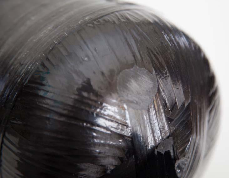
27 Level 3 Abrasion damage: 6.3 Cuts 3 Cuts This type of damage consists of cuts caused by contact with sharp objects that penetrate into the composite material, effectively reducing its thickness at the point of contact. This damage is similar in some ways to abrasion damage. The ECLIPSE range has a fiberglass layer on the sidewall of the cylinder to enable labels to be protected. You can see the glass as a grey layer whereas the domes are black from the carbon fiber. Level 1 damage: Consists of cuts to the outer gel coating or resin or cuts into the carbon fiber or glass fiber layer of less than 0.02 deep. 27


28 Level 2 Cut damage: Cuts that are between 0.02 and 0.03 deep. 28


29 Level 3 Cut damage: Cuts that are over 0.03 deep 29


30 6.4 Impact damage Impact damage may appear as cracks in the resin, as delamination or as cuts in the overwrap. All cylinders that show evidence of impact damage must be visually inspected for evidence of indentation of the internal surface of the metal liner. Two levels of impact damage are recognized: Level 1 and Level 3 (there is no Level 2). Level 1 damage: Light damage, such scuffs and gelcoat chipping do not require repair. The cylinder may be returned to service. Level 3 damage: The cylinder must be rejected if impact damage causes a large area of frosting, delamination of fibers or other such readily noticeable structural damage. Reject cylinders with any visual evidence of dents on the internal surface of the metal liner. Level 1 Impact damage: 30

.")
31 Level 3 Impact damage: 6.5 Delamination Delamination is a separation of composite overwrap layers or strands. It may also appear as a whitish patch, such as a blister or an air space beneath the surface. Delamination is usually a result of an impact, cut or exposure to temperatures of more than 200 F. Level 1 damage: Light damage, such as a small area where the carbon fiber is frosted, does not require repair (see Level 1 impact, above). The cylinder may be returned to service. Level 2 damage: If any defect does not exceed a width of 2 inches (50 mm), the cylinder may be repaired and returned to service. Level 3 damage: Delamination damage greater than Level 2 requires the cylinder to be rejected. 31
.")
32 Level 2 Delamination 6.6 Heat or fire damage Elevated heat exposure a different condition than obvious heat or fire damage may or may not result in permanent heat damage to a cylinder. Elevated heat exposure occurs when the cylinder itself, absent any outer protection, has been subjected to a temperature environment in excess of 180 F (80 C). A composite cylinder is not intended for prolonged use in any environment that would result in composite overwrap temperatures in excess of 180 o F. However, temporary short-term exposure to air temperatures in excess of 180 o F in a firefighting environment is not cause for cylinder condemnation. As extensive field experience has shown, a composite cylinder used within a selfcontained breathing apparatus (SCBA) carried by a firefighter can withstand limited exposure to elevated temperatures without damage (also see Section 5.3, above). CAUTION: Other components used with the cylinder may not be suitable for use at temperatures of 180 o F (80 o C). Please refer to the OEM s guidelines for further information. Developed composite material temperatures in excess of the original cure temperature of the composite will cause discoloration of the resin. This discoloration can range from a very light golden or caramel color to a deep, brownish-black appearance. Light discoloration will occur naturally over time with continued direct exposure to sunlight and may not necessarily be a result of elevated temperature exposure. The discoloration may also be caused from soot or smoke from a firefighting environment. Normally, the degree and depth of discoloration is dependent on 32
33 either the temperature or duration of exposure. The higher the temperature, or the longer the duration of exposure, the darker the resin system will become. Pay close attention to the condition of any attachments such as valves, decals, stickers, stencils, exposed metal (e.g., aluminum liner ends or necks) and the outer protective paint; these can indicate prolonged exposure to heat or fire. If the valve is available, the condition of the pressure relief device (PRD) should be evaluated to assess the extent of any heat effects. Fire damage to cylinders or equipment is also shown by melted plastics, burned or frayed straps and discolored components. Clean the cylinder and remove smoke residue and dirt from the surface before conducting a thorough inspection. Any cylinder used in equipment that has experienced fire damage should be rejected. Fire damage is shown by charring or burning of the composite, paint, labels, valve materials, melted resin, absence of some or all of the resin and/or by paint damage (e.g., bubbling or melting). Two levels of heat or fire damage are recognized: Level 1 and Level 3 (there is no Level 2). Level 1 damage occurs when the surface of the clear gel coat, paint or composite is soiled from smoke or other contaminants but is intact underneath with no evidence that the resin has been burned. In this case, a cylinder can be returned to service after cleaning. This smoke-darkened cylinder only has Level 1 damage. After cleaning, it can be returned to service. Over time, resin can become tinted due to exposure to heat and smoke. This is not unusual, and the cylinder can be returned to service. Light discoloration of the resin gel-coat or painted surface may be evaluated by cleaning the surface with a fine-grit Scotchbrite scrubbing pad, fine steel wool or 320-grit sandpaper, as well as liquid dishwashing detergent mixed with warm water. An immediate color change back to an off-white color indicates that the cause of the 33

34 discoloration has no significant depth. This method may also be used to evaluate the condition of a painted surface that shows no evidence of blistering or charring. After this evaluation, the cylinder must pass a pressure test. Level 3 damage like this requires that a cylinder be rejected. Level 3 damage (above photograph): Cylinders showing excessive heat damage must be rejected. Cylinders known to have been left unattended in a fire and exhibiting any evidence of heat damage must be rejected. Evidence of heat damage includes charring or melting of the composite or any attachments, valve components, protective layers, stickers or paint. Evidence can also include blistering of a protective layer. The composite would appear dark brown or black in color and would remain unchanged when cleaned and evaluated, as noted above. The original manufacturer s label may be totally illegible due to the darkness of the resin. If the valve is available, the condition of the pressure relief device (PRD) should be evaluated to assess the extent of any temperature exposure. Cylinders known to have been subjected to the direct action of fire (i.e., prolonged impingement by flame) must be rejected. Evidence of fire damage might include signs of actual burning. Fire damage could occur either in an isolated area of the cylinder surface or over a wider area. 34


35 6.7 Structural damage A cylinder is rendered unserviceable if there is any evidence of surface bulges or depressions, distorted valve connections or deformation of the aluminum liner revealed by visual examination of the cylinder interior. Contact Luxfer if you are uncertain about how to distinguish such normal conditions from actual damage. 6.8 Chemical attack Chemicals can dissolve, corrode, soften, remove or ruin cylinder composite materials. They can also cause bubbling, pitting or extreme dulling of the resin; cause deterioration of the resin or protective paint layer; or create multiple fractures transverse to the direction of the fiber. Sometimes solvents can cause the cylinder to become sticky to the touch. Cylinders with evidence of such damage must be rejected. If a carbon composite cylinder has been clearly damaged by chemicals, it must be rejected. 35


36 7. Repair procedure All cylinders that have been repaired must be subjected to a pressure test before being returned to service. After pressure test, the repair sites must be carefully examined for any lifting, peeling or delamination of the composite material. Any cylinders showing signs of lifting, peeling or delamination must be rejected. Place the cylinder on a table or bench with the damaged area uppermost and easy to reach. Check the damage site carefully in accordance with allowable defect limits. Ensure the surface is clean and dry. Slightly roughen the damaged area with either fine sandpaper or a Scotchbrite scrubbing pad to prepare an acceptable surface for proper resin adhesion. 36


37 Mix a sufficient amount of two-part epoxy resin according to the resin manufacturer s instructions. Epoxy resin sets up quickly, so it is important to apply it without delay after it has been mixed. Apply a sufficient amount of the epoxy resin to the damaged area, using the applicator to thoroughly coat and burnish down any loose fibers. Completely fill the damaged area with resin. Where additional protection is required, apply a slightly oversized piece of fiberglass surface veil over the damaged area. Apply a thin layer of resin over the veil, making sure that the veil and damaged area are completely covered. Where a superior surface finish is required, use shrink tape. Affix a piece of unidirectional shrink tape, approximately 6 inches (150mm) longer than the damaged area, with outer surface of tape facing downwards, over the damage with ordinary adhesive tape. Apply heat to the tape with a hot air dryer to cause shrinkage. Peel off the tape after the epoxy resin has fully cured. Allow the epoxy resin to set, typically 5 to 10 minutes. Then move the cylinder to a protected location and leave it undisturbed until the epoxy resin is fully cured in accordance with the resin manufacturer s guidelines. Apply a desired finish to the repair. Pressure test the cylinder before returning it to service. 37
38 8. Final operations 8.1 Drying and cleaning The following procedures are recommended for cleaning composite cylinders: EXTERNAL CLEANING PROBLEM CLEANING METHOD Moisture and light soil Wipe with a soft cloth. Oil and grease Dirt and Soot Degrease with mild soap and water, wipe or blow dry. Clean with mild soap and water, wipe or blow dry. INTERNAL CLEANING PROBLEM White deposits or staining Odor CLEANING METHOD Tumble with walnut shells, plastic chips or other non-aggressive media. Then wash with hot water and thoroughly dry. Do not use heated air above 160 F or place in an oven to dry. Wash with hot water and thoroughly dry. Do not use heated air above 160 F or place in an oven to dry. For any problems other than the above, please contact Luxfer Gas Cylinders for assistance. 38
39 8.2 Repainting Luxfer does not recommend the removal of the existing paint from cylinders, since this can only be carried out effectively by using specialized equipment. Never use paint strippers, burning techniques or solvents to remove paints from aluminum or composite surfaces. If the cylinder is dirty, clean the exterior surface with a mild water-based detergent, rinse and dry the cylinder thoroughly. Do not use heat to dry the cylinder. If any damage to the cylinder composite materials is evident, have the cylinder visually inspected by an authorized technician before painting. If the composite materials are undamaged, lightly rub down the cylinder exterior with 320-grit or finer sandpaper to prepare the surface for good paint adhesion. Retouch damaged paint areas with air-drying paint. Never heat the cylinder to dry or cure paint. The type of air-drying paint is not critical, but flame-retardant epoxy or polyurethane paint is recommended. Do not thin solvent-based paint with toluene, xylene or other aggressive solvents. Water-based polyurethane paint has been found to have good flame-resistant properties. Spray painting normally gives a better finish. If the entire cylinder is to be painted, contact Luxfer for recommendations. Do not paint over the cylinder label. If painting near the label, mask off the label to protect it and ensure future legibility (a regulatory requirement). Take care not to spray paint onto the top face of the cylinder neck since paint in this area can impair proper valve sealing. Contact Luxfer if you have questions or require additional information. 8.3 Valve insertion Selection of valves and pressure-relief devices (PRD) must conform to the requirements in the current edition of Compressed Gas Association (CGA) Pamphlet S-1.1 and must comply with requirements of 49 CFR (d) and (g). Note also that the adequacy of the pressure relief device is determined by a bonfire test as prescribed in CFFC-10. The rated bursting pressure of a rupture disk at ambient temperature must be not less than 83 percent or more than 100 percent of the cylinder test pressure. Before inserting the valve into the cylinder, carefully inspect it and, if necessary, repair it in accordance with the recommendations of the valve manufacturer and or SCBA manufacturer. Do not install any valve that has not passed an inspection. Failure to follow these guidelines can lead to unsatisfactory in-service performance. The valve threads should be free from damage. Use an appropriate gauge to ensure that the valve complies with the correct thread specification. The mating surface on the valve should be smooth and free from damage. Damaged or distorted valve threads can damage cylinder threads. Damage to the mating surface can prevent sealing and damage the top sealing face of the cylinder. 39
40 Check to make sure that the O-ring groove and threads in the cylinder are clean and free from damage. Install a new O-ring on the valve in accordance with the valve manufacturer s or SCBA manufacturer s recommendations. A thin smear of silicone, hydrocarbon-free, oxygen-compatible grease may be applied to the bottom three or four threads to provide lubrication but take care not to apply grease to the bottom face of the valve stem. Only a small amount of grease is necessary. Too much grease can cause sealing problems. CAUTION: Hydrocarbon-based lubricants must not be used on cylinders containing oxygen or oxygen-enriched gas! Insert the valve into the cylinder neck and tighten first by hand to make sure the threads are properly aligned. Then finish tightening the valve in accordance with the OEM or system manufacturer s recommendations. If no manufacturer s data are available, the following table may be used for recommended torque levels: TABLE 2: Recommended Valve Torque Range THREAD TORQUE RANGE M ft.lbs ( NM) UNF 2B ft.lbs ( NM) UNF 2B ft.lbs ( NM) UNF 2B ft.lbs ( NM) CAUTION: The valve manufacturer should be contacted to ensure that these torque levels are appropriate. 8.4 Destruction of condemned or expired cylinders To destroy condemned or expired cylinders, drill a minimum 1/2-inch (13mm) hole all the way through the cylinder wrapping and liner so that the cylinder cannot hold gas. WARNING: Even if completely vented, the cylinder can contain a significant amount of residual gas. 40
41 9. Summary 11 FILLING THE SCBA CYLINDER Care and maintenance of a Luxfer carbon composite cylinder ALWAYS: Always be alert for air leaks with each fill. Always keep the threads and cylinder interior dry and free from oil, dirt and other contaminants. Always fill cylinders with proper gas recommended by the original equipment manufacturer. Always follow appropriate inspection recommendations. Always follow the valve manufacturers or SCBA manufacturer s installation procedures and recommendations. Always maintain accessory equipment used with your cylinder in strict accordance with the manufacturer s recommendations. NEVER: Never fill a cylinder if it leaks. Never fill a damaged cylinder. Never fill a cylinder if it is past its required requalification date. Never fill a composite cylinder past its allowable life. Never completely discharge a cylinder (except when you are planning to remove the valve) since it can lead to moisture entering into the cylinder. Never use hydrocarbon-based lubricants with oxygen. Never use non-oxygen-compatible components with oxygen or oxygen-enriched gases. Never over-torque a valve. Never remove, obscure or alter the manufacturer s labels. Never use a cylinder that has been exposed to an extremely corrosive atmosphere or environment without having it properly inspected and tested. Never use a cylinder that has been exposed to extreme heat or fire for a prolonged period without having it properly tested. 41
42 APPENDIX 1: Sample label 42


43 APPENDIX 2: Removal and refitting of protective caps, boots Luxfer composite cylinders used in SCBA applications may be fitted with high-impact polymer caps and boots that are bonded to the cylinder with an adhesive. This procedure describes how to remove these caps and boots so that the entire composite surface may be examined during requalification. Tools required: Thin, flexible metal strip and a Loctite adhesive kit. Procedure: Carefully slip the metal strip between the cap or boot and cylinder as shown in Photo 1 to a depth of 40-50mm. Continue to insert the metal strip in this manner every 20mm around the circumference of the cylinder. Photo 1: Note depth of blade under cap. The adhesive bead is 20-30mm from the edge. Photo 2: Cylinder surface after cap has been removed. Once the metal strip has been passed between the cylinder and cap all the way around, the cap may be removed by lifting the cap by the edge while working around the cylinder. Perform the same procedure to remove the boot from the base-end of the cylinder. Any remaining adhesive on the cylinder or cap/boot may be removed by rubbing the surface with a finger or cloth, if necessary, by using isopropyl alcohol.
 Luxfer recommends using Loctite adhesive for bonding caps and boots. This adhesive is available for purchase from Luxfer. Contact Luxfer Customer Service for information.")
44 Photo 3: Applying adhesive. Installation of new caps and boots: Caps and boots are normally reusable. (New caps and boots may be purchased by contacting Luxfer Customer Service.) Luxfer recommends using Loctite adhesive for bonding caps and boots. This adhesive is available for purchase from Luxfer. Contact Luxfer Customer Service for information. Apply a small bead of adhesive to the inside surface of the cap approximately 20 to 30mm from the outside edge (See Photo 3). Immediately after applying the resin, place the cap firmly over the cylinder dome and press in place. Do not use heat to cure the adhesive! Heat may have an adverse effect on the cylinder s performance. 44
East Building, PHH-30 U.S. Department New Jersey Avenue S.E. of Transportation Washington, D.C EXPIRATION DATE: June 30, 2015
 November 14, 2014 East Building, PHH-30 U.S. Department 1200 New Jersey Avenue S.E. of Transportation Washington, D.C. 20590 Pipeline and Hazardous Materials Safety Administration DOT-SP 16219 EXPIRATION
Composite. care. cylinder. for responsible paintballers!
 Composite cylinder care for responsible paintballers! Before you use or fill your composite cylinder, remember: Always... Never... Always have your cylinder inspected or retested if it shows signs of gouges,
EXPIRATION DATE: (FOR RENEWAL, SEE 49 CFR ) 1. GRANTEE: Structural Composites Industries (SCI) Pomona, CA
 1. GRANTEE: Structural Composites Industries (SCI) Pomona, CA") East Building, PHH-30 1200 New Jersey Avenue S.E. U.S. Department of Transportation Washington, D.C. 20590 Pipeline and Hazardous Materials Safety Administration DOT-SP 13583 (NINTH REVISION) EXPIRATION
East Building, PHH-30 1200 New Jersey Avenue S.E. U.S. Department of Transportation Washington, D.C. 20590 Pipeline and Hazardous Materials Safety Administration DOT-SP 13583 (NINTH REVISION) EXPIRATION
East Building, PHH-30 U.S. Department New Jersey Avenue S.E. of Transportation Washington, D.C DOT-SP (FOURTH REVISION)
") East Building, PHH-30 U.S. Department 1200 New Jersey Avenue S.E. of Transportation Washington, D.C. 20590 Pipeline and Hazardous Materials Safety Administration DOT-SP 15260 (FOURTH REVISION) EXPIRATION
East Building, PHH-30 U.S. Department 1200 New Jersey Avenue S.E. of Transportation Washington, D.C. 20590 Pipeline and Hazardous Materials Safety Administration DOT-SP 15260 (FOURTH REVISION) EXPIRATION
East Building, PHH-30 U.S. Department New Jersey Avenue S.E. of Transportation Washington, D.C DOT-SP (NINTH REVISION)
") East Building, PHH-30 U.S. Department 1200 New Jersey Avenue S.E. of Transportation Washington, D.C. 20590 Pipeline and Hazardous Materials Safety Administration DOT-SP 14576 (NINTH REVISION) EXPIRATION
East Building, PHH-30 U.S. Department 1200 New Jersey Avenue S.E. of Transportation Washington, D.C. 20590 Pipeline and Hazardous Materials Safety Administration DOT-SP 14576 (NINTH REVISION) EXPIRATION
EXPIRATION DATE: September 30, 2013
 U.S. Department East Building, PHH 30 of Transportation 1200 New Jersey Avenue, Southeast Pipeline and Hazardous Materials Safety Administration DOT-SP 10945 (TWENTYFOURTH REVISION) Washington, D.C. 20590
East Building, PHH-30 U.S. Department New Jersey Avenue S.E. of Transportation Washington, D.C DOT-SP (EIGHTEENTH REVISION)
") East Building, PHH-30 U.S. Department 1200 New Jersey Avenue S.E. of Transportation Washington, D.C. 20590 Pipeline and Hazardous Materials Safety Administration DOT-SP 11194 (EIGHTEENTH REVISION) EXPIRATION
East Building, PHH-30 U.S. Department 1200 New Jersey Avenue S.E. of Transportation Washington, D.C. 20590 Pipeline and Hazardous Materials Safety Administration DOT-SP 11194 (EIGHTEENTH REVISION) EXPIRATION
400 Seventh Street, S.W. of Transportation Washington, D.C EXPIRATION DATE: February 28, 2010
 U.S. Department 400 Seventh Street, S.W. of Transportation Washington, D.C. 20590 Pipeline and Hazardous Materials Safety Administration DOT-SP 10945 (EIGHTEENTH REVISION) EXPIRATION DATE: February 28,
EXPIRATION DATE: June 30, 2011
 East Building, PHH- U.S. Department of Transportation Washington, D.C. 20590 Pipeline and Hazardous Materials Safety Administration DOT-SP 11194 (FOURTEENTH REVISION) 1200 New Jersey Avenue S.E. EXPIRATION
PIPELINE AND HAZARDOUS MATERIAL SAFETY ADMINISTRATION CYLINDER REQUALIFICATION FACILITY INSPECTION REPORT GENERAL INFORMATION
 PIPELINE AND HAZARDOUS MATERIAL SAFETY ADMINISTRATION CYLINDER REQUALIFICATION FACILITY INSPECTION REPORT Inspection : RIN Number: Company Name and Address: Company Officials: Title: Interviewed GENERAL
Minimum test pressure (psig) 2. Requalification period (years) DOT psig 5. non-corrosive service ( see
 2. Requalification period (years) DOT psig 5. non-corrosive service ( see") 180.209 Requirements for requalification of specification cylinders. (a) Periodic qualification of cylinders. (1) Each specification cylinder that becomes due for periodic requalification, as specified
180.209 Requirements for requalification of specification cylinders. (a) Periodic qualification of cylinders. (1) Each specification cylinder that becomes due for periodic requalification, as specified
BASIC REQUIREMENTS FOR FIBER REINFORCED PLASTIC (FRP) TYPE 3FC COMPOSITE CYLINDERS
 TYPE 3FC COMPOSITE CYLINDERS") 1 DOT FRP - 1 STANDARD DATE: Original; July 1, 1981 Revision 1; March 15, 1982 Revision 2; February 15, 1987 BASIC REQUIREMENTS FOR FIBER REINFORCED PLASTIC (FRP) TYPE 3FC COMPOSITE CYLINDERS 178.AA Fiber
1 DOT FRP - 1 STANDARD DATE: Original; July 1, 1981 Revision 1; March 15, 1982 Revision 2; February 15, 1987 BASIC REQUIREMENTS FOR FIBER REINFORCED PLASTIC (FRP) TYPE 3FC COMPOSITE CYLINDERS 178.AA Fiber
[Reserved] Packagings ICC 3 1 3AA 3AL 3AX 3A480X 3AAX
![[Reserved] Packagings ICC 3 1 3AA 3AL 3AX 3A480X 3AAX](/thumbs/80/80792632.jpg "[Reserved] Packagings ICC 3 1 3AA 3AL 3AX 3A480X 3AAX") 173.300 [Reserved] 173.301 General requirements for shipment of compressed gases and other hazardous materials in cylinders, UN pressure receptacles and spherical pressure vessels. (a) General qualifications
173.300 [Reserved] 173.301 General requirements for shipment of compressed gases and other hazardous materials in cylinders, UN pressure receptacles and spherical pressure vessels. (a) General qualifications
DOT-SP 8391 (FIFTHTEENTH REVISION) EXPIRATION DATE: (FOR RENEWAL, SEE 49 CFR )
 EXPIRATION DATE: (FOR RENEWAL, SEE 49 CFR )") U.S. Department East Building, PHH 30 of Transportation 1200 New Jersey Avenue, Southeast Washington, Pipeline and Hazardous Materials Safety Administration D.C. 20590 DOT-SP 8391 (FIFTHTEENTH REVISION)
U.S. Department East Building, PHH 30 of Transportation 1200 New Jersey Avenue, Southeast Washington, Pipeline and Hazardous Materials Safety Administration D.C. 20590 DOT-SP 8391 (FIFTHTEENTH REVISION)
East Building, PHH-30 U.S. Department New Jersey Avenue S.E. of Transportation Washington, D.C DOT-SP 7218 (NINETEENTH REVISION)
") East Building, PHH-30 U.S. Department 1200 New Jersey Avenue S.E. of Transportation Washington, D.C. 20590 Pipeline and Hazardous Materials Safety Administration DOT-SP 7218 (NINETEENTH REVISION) EXPIRATION
East Building, PHH-30 U.S. Department 1200 New Jersey Avenue S.E. of Transportation Washington, D.C. 20590 Pipeline and Hazardous Materials Safety Administration DOT-SP 7218 (NINETEENTH REVISION) EXPIRATION
East Building, PHH-30 U.S. Department New Jersey Avenue S.E. of Transportation Washington, D.C DOT-SP 8718 (SEVENTEENTH REVISION)
") East Building, PHH-30 U.S. Department 1200 New Jersey Avenue S.E. of Transportation Washington, D.C. 20590 Pipeline and Hazardous Materials Safety Administration DOT-SP 8718 (SEVENTEENTH REVISION) EXPIRATION
East Building, PHH-30 U.S. Department 1200 New Jersey Avenue S.E. of Transportation Washington, D.C. 20590 Pipeline and Hazardous Materials Safety Administration DOT-SP 8718 (SEVENTEENTH REVISION) EXPIRATION
bxi of ,LT COMPLETE REFERENCE MANUAL FOR INFORMATION REGARDING YOUR CARLETON PRESSURE VESSEL.
 . -.....-.- L.A -- bxi of.. 46-0,LT COMPLETE REFERENCE MANUAL FOR INFORMATION REGARDING YOUR CARLETON PRESSURE VESSEL. TABLEOF CONTENTS General Information About your Pressure Vessel..... 3 11 Introduction...
EXPIRATION DATE: January 31, 2015
 U.S. Department East Building, PHH 30 of Transportation 1200 New Jersey Avenue, Southeast Pipeline and Hazardous Materials Safety Administration DOT-SP 7235 (TWENTY-THIRD REVISION) Washington, D.C. 20590
DOT-CFFC BASIC REQUIREMENTS (FIFTH REVISION) PAGE 1
 PAGE 1") DOT-CFFC BASIC REQUIREMENTS (FIFTH REVISION) PAGE 1 CFFC-1 SCOPE APPENDIX A BASIC REQUIREMENTS FOR FULLY WRAPPED CARBON-FIBER REINFORCED ALUMINUM LINED CYLINDERS(DOT-CFFC) DATE: MARCH 2007 (FIFTH REVISION)
DOT-CFFC BASIC REQUIREMENTS (FIFTH REVISION) PAGE 1 CFFC-1 SCOPE APPENDIX A BASIC REQUIREMENTS FOR FULLY WRAPPED CARBON-FIBER REINFORCED ALUMINUM LINED CYLINDERS(DOT-CFFC) DATE: MARCH 2007 (FIFTH REVISION)
Wayne Chaney Investigator, Southern Region Field Operations
 Wayne Chaney Investigator, Southern Region Field Operations http://phmsa.dot.gov/hazmat Month/Year - 1 - Agenda Approval requirements for obtaining RINs Cylinder requalification process DOT Inspections
A REFERENCE GUIDE FOR REQUALIFICATION OF GAS CYLINDERS
 A REFERENCE GUIDE FOR REQUALIFICATION OF GAS CYLINDERS AIGA 090/14 Asia Industrial Gases Association 3 HarbourFront Place, #09-04 HarbourFront Tower 2, Singapore 099254 Tel : +65 6276 0160 Fax : +65 6274
Other Si min/max. Cr min/max. 0.4/ / / / Bal.
 178.46 Specification 3AL seamless aluminum cylinders. (a) Size and service pressure. A DOT 3AL cylinder is a seamless aluminum cylinder with a imum water capacity of 1000 pounds and minimum service pressure
A Rationale for Pressure Relief Device(s) Qualification Requirements (LH2)
 Qualification Requirements (LH2)") UN-GTR PART A INSERTION Stand 09.02.2011, 17:20 Uhr A.3.3 HYDROGEN STORAGE SYSTEM The hydrogen storage system consists of all components that form the primary pressure boundary of the stored hydrogen in
UN-GTR PART A INSERTION Stand 09.02.2011, 17:20 Uhr A.3.3 HYDROGEN STORAGE SYSTEM The hydrogen storage system consists of all components that form the primary pressure boundary of the stored hydrogen in
5.0 INSPECTING, FILLING AND LABELING SMALL CYLINDERS
 5.0 INSPECTING, FILLING AND LABELING SMALL CYLINDERS 23 24 5.0 INSPECTING, FILLING AND LABELING SMALL CYLINDERS INSPECTING, FILLING AND LABELING SMALL CYLINDERS Pre-fill Visual Check Safely inspecting
PRESSURE RETEST. 49 CFR, (g) Co#: Vin#: DOT Spec: MAWP:
 Co#: Vin#: DOT Spec: MAWP:") PRESSURE RETEST 49 CFR, 180.407(g) Co#: Vin#: Spec: MAWP: Retest Date: Location: *External Inspection Performed: *Internal Inspection Performed: Test Pressure: psig Held for: min. (Must be at least 10
PRESSURE RETEST 49 CFR, 180.407(g) Co#: Vin#: Spec: MAWP: Retest Date: Location: *External Inspection Performed: *Internal Inspection Performed: Test Pressure: psig Held for: min. (Must be at least 10
Material Handling and Storage of compressed gases and Air equipment
 Material Handling and Storage of compressed gases and Air equipment Compressed gases can be toxic, flammable, oxidizing, corrosive, inert, or some combination of these hazards. Compressed gas cylinders
Cylinder HAZMAT & Fill Station Operations Compliance. PSI/PCI, Inc. William L. (Bill) High & Mark A. Gresham
 High & Mark A. Gresham") Cylinder HAZMAT & Fill Station Operations Compliance PSI/PCI, Inc. William L. (Bill) High & Mark A. Gresham Purpose of Hazmat Training Department of Transportation (DOT) Code of Federal Regulations requires
Cylinder HAZMAT & Fill Station Operations Compliance PSI/PCI, Inc. William L. (Bill) High & Mark A. Gresham Purpose of Hazmat Training Department of Transportation (DOT) Code of Federal Regulations requires
EXPIRATION DATE: March 31, GRANTEE: Hexagon Ragasco AS Raufoss, Norway (U.S. Agent: Hexagon Ragasco North America Inc.
 U.S. Department East Building, PHH 30 of Transportation 1200 New Jersey Avenue, Southeast Pipeline and Hazardous Materials Safety Administration Washington, D.C. 20590 DOT-SP 12706 (TENTH REVISION) EXPIRATION
This written Compressed Gas Plan is kept at the corporate office and in the written Safety & Health Program.
 Safety & Health Program 10627 Midwest Industrial Boulevard, St. Louis, MO Phone: 314-785-6425 Fax: 314-785-6426 Compressed Gas Plan Purpose It is the policy of EMA to permit only trained and authorized
East Building, PHH-30 U.S. Department New Jersey Avenue S.E. of Transportation Washington, D.C DOT-SP (TWENTY-THIRD REVISION)
") East Building, PHH-30 U.S. Department 1200 New Jersey Avenue S.E. of Transportation Washington, D.C. 20590 Pipeline and Hazardous Materials Safety Administration DOT-SP 11054 (TWENTY-THIRD REVISION) EXPIRATION
East Building, PHH-30 U.S. Department 1200 New Jersey Avenue S.E. of Transportation Washington, D.C. 20590 Pipeline and Hazardous Materials Safety Administration DOT-SP 11054 (TWENTY-THIRD REVISION) EXPIRATION
EKC International FZE. Safety Instructions For Handling & Inspection Manual For Refillable Seamless Steel Gas Cylinders
 Safety Instructions For Handling & Inspection Manual For Refillable Seamless Steel Gas Cylinders MKT/WI/02 Page 1 of 6 1. Sensitivity of cylinder materials to operating conditions and their solution. Material
Permanent expansion means a permanent increase in a cylinder's volume after the test pressure is released.
 Subpart C Qualification, Maintenance and Use of Cylinders Source: 67 FR 51660, Aug. 8, 2002, unless otherwise noted. 180.201 Applicability. This subpart prescribes requirements, in addition to those contained
Process Name Compressed Gas Cylinders Program
 CNM WAY PROCESS CNM Process Name Compressed Gas Cylinders Program (07/11/2018 Revision) Overview of Compressed Gas Cylinders Program Purpose: To prevent injury from failure of compressed gas cylinders
INSTRUCTION MANUAL FOR EBA MINUTE SELF-CONTAINED SELF RESCUER (SCSR) Manual Number: NH13747 Revision: A, ECN 2384 September 7, 2001
 Manual Number: NH13747 Revision: A, ECN 2384 September 7, 2001") INSTRUCTION MANUAL FOR EBA 6.5 60 MINUTE SELF-CONTAINED SELF RESCUER (SCSR) Manual Number: NH13747 Revision: A, ECN 2384 September 7, 2001 Page 1 of 20 CONTENTS PAGE INTRODUCTION 3 GENERAL INFORMATION..3
INSTRUCTION MANUAL FOR EBA 6.5 60 MINUTE SELF-CONTAINED SELF RESCUER (SCSR) Manual Number: NH13747 Revision: A, ECN 2384 September 7, 2001 Page 1 of 20 CONTENTS PAGE INTRODUCTION 3 GENERAL INFORMATION..3
International Civil Aviation Organization DANGEROUS GOODS PANEL (DGP) MEETING OF THE WORKING GROUP OF THE WHOLE. Montreal, 18 to 22 April 2005
 MEETING OF THE WORKING GROUP OF THE WHOLE. Montreal, 18 to 22 April 2005") International Civil Aviation Organization WORKING PAPER 24/3/05 DANGEROUS GOODS PANEL (DGP) MEETING OF THE WORKING GROUP OF THE WHOLE Montreal, 18 to 22 April 2005 Agenda Item 2: Development of recommendations
International Civil Aviation Organization WORKING PAPER 24/3/05 DANGEROUS GOODS PANEL (DGP) MEETING OF THE WORKING GROUP OF THE WHOLE Montreal, 18 to 22 April 2005 Agenda Item 2: Development of recommendations
User Manual. Carbon Composite Cylinder. Alternative Fuel Cylinders
 Carbon Composite Cylinder User Manual Alternative Fuel Cylinders Guide to the use, maintenance and periodic inspection of Luxfer carbon composite AF cylinders Page 1 Table of Contents 1.0 Introduction....................................................................
P-04 Stainless Steel Corrugated Hoses and Metal Bellows Expansion Joints
 Guideline No.P-04 (201510) P-04 Stainless Steel Corrugated Hoses and Metal Bellows Expansion Joints Issued date: 20 th October 2015 China Classification Society Foreword This Guideline is a part of CCS
EASTERN ENERGY SERVICES PTE LTD. 60 Kaki Bukit Place #02-19 Eunos Tech Park Singapore, SG Singapore Telephone: Fax:
 2 Table Of Contents 1. Introduction 3 2. About this Manual 3 3. Contacting YZ Systems 3 4. Vessel Components 4 5. Specifications 5 6. Application 6 7. Theory of Operation 7 8. DuraSite Installation & Use
INSPECTION FOCUS ON:
 Newsletter of the South African National Accreditation System Issue 28, October 2016 INSPECTION FOCUS ON: INSPECTION OF GAS CYLINDERS AND OCCUPATIONAL HYGIENE REGULATIONS BY LINDA GRUNDLINGH 1. Occupational
East Building, PHH-30 U.S. Department New Jersey Avenue S.E. of Transportation Washington, D.C DOT-SP (ELEVENTH REVISION)
") East Building, PHH-30 U.S. Department 1200 New Jersey Avenue S.E. of Transportation Washington, D.C. 20590 Pipeline and Hazardous Materials Safety Administration DOT-SP 11808 (ELEVENTH REVISION) EXPIRATION
East Building, PHH-30 U.S. Department 1200 New Jersey Avenue S.E. of Transportation Washington, D.C. 20590 Pipeline and Hazardous Materials Safety Administration DOT-SP 11808 (ELEVENTH REVISION) EXPIRATION
CLASS D - SENSITIVE LEAK TEST GAS AND BUBBLE METHOD. 1.1 To provide definitive requirements for PNEUMATIC pressure testing of piping systems.
 Page 1 of 7 CLASS D - SENSITIVE LEAK TEST GAS AND BUBBLE METHOD 1. SCOPE 1.1 To provide definitive requirements for PNEUMATIC pressure testing of piping systems. 1.2 The piping system as used herein is
High Pressure Composite Cylinder
 High Pressure Composite Cylinder Composite cylinder design Analysis Qualification Testing Prediction of structural behavior of a composite cylinder is complicated because of the anisotropy of composite
Management Plan for Compressed Gas
 IEA, INC. N E W P R A G U E A R E A S C H O O L S I S D # 7 2 1 A Service-Disabled Veteran-Owned Small Business Contact Us: BROOKLYN PARK OFFICE 9201 W. BROADWAY, #600 BROOKLYN PARK, MN 55445 763-315-7900
User Operation Manual and Safety Instructions
 PCP Airgun Charging Station 74 cu.ft. / 98 cu. ft. Carbon Fiber Tank & Accessories User Operation Manual and Safety Instructions BRAND: Air Venturi DESCRIPTION: PCP Airgun Charging System FILL PRESSURE:
product use, care, & inspection Document Released: January, 10, 2012 Approved By: Bryce Merrick
 product use, care, & inspection Document Released: January, 10, 01 Approved By: Bryce Merrick product use, care, & inspection Contents product use 03 product warning 03 tuff bucket ANATomy 04 how to properly
PARTS, SERVICE & REPAIR BULLETIN
 WH4C PARTS, SERVICE & REPAIR BULLETIN 400 SERIES HEAVY DUTY WELDING HANDLE Manual No: 0056-3763 Issue Date: October 07, 03 Revision: AA VictorTechnologies.com Table of Contents SECTION : GENERAL SAFETY
INSTRUCTION MANUAL EBA-75 CLOSED-CIRCUIT ESCAPE RESPIRATOR (CCER) CAPACITY 3
 CAPACITY 3") INSTRUCTION MANUAL FOR THE EBA-75 CLOSED-CIRCUIT ESCAPE RESPIRATOR (CCER) CAPACITY 3 Manual Number: NH24053 Revision: A, ECN 3590 December 14, 2015 Page 1 of 13 CONTENTS PAGE INTRODUCTION... 3 GENERAL
INSTRUCTION MANUAL FOR THE EBA-75 CLOSED-CIRCUIT ESCAPE RESPIRATOR (CCER) CAPACITY 3 Manual Number: NH24053 Revision: A, ECN 3590 December 14, 2015 Page 1 of 13 CONTENTS PAGE INTRODUCTION... 3 GENERAL
Limited quantities of compressed gases.
 173.306 Limited quantities of compressed gases. (a) Limited quantities of compressed gases for which exceptions are permitted as noted by reference to this section in 172.101 of this subchapter are excepted
300 BAR HIGH STRENGTH SEAMLESS STEEL GAS CYLINDERS
 300 BAR HIGH STRENGTH SEAMLESS STEEL GAS CYLINDERS Doc 124/18 Revision of Doc124/11 EUROPEAN INDUSTRIAL GASES ASSOCIATION AISBL AVENUE DES ARTS 3-5 B 1210 BRUSSELS Tel: +32 2 217 70 98 Fax: +32 2 219 85
Jupiter Type 4 Tube Owner s Manual
 Jupiter Type 4 Tube Owner s Manual Forward Thank you for purchasing a Cimarron Composites Type 4 Tube. The content of this manual contains information for the use of Cimarron Gas Tubes. Please read this
Transport of gas tanks for motor vehicles
 Committee of Experts on the Transport of Dangerous Goods and on the Globally Harmonized System of Classification and Labelling of Chemicals Transport of gas tanks for motor vehicles Submitted by the expert
CITY AND COUNTY OF DENVER CR&CF RISK UNIT Compressed Gas Safety Standard
 CITY AND COUNTY OF DENVER CR&CF RISK UNIT 65.5.11 Compressed Gas Safety Standard 1.0 Introduction 2.0 Scope This standard has been developed to protect all City and County of Denver employees and contractors
USE OF RESIDUAL PRESSURE VALVES
 USE OF RESIDUAL PRESSURE VALVES AIGA 063/16 Revision of AIGA 063/14 Asia Industrial Gases Association 3 HarbourFront Place, #09-04 HarbourFront Tower 2, Singapore 099254 Tel : +65 6276 0160 Fax : +65 6274
Guide for Evaluating Your Hose Assembly Supplier
 Guide for Evaluating Your Hose Assembly Supplier Supplier Evaluation Checklist, and How to Clearly Define Application Requirements Safe, reliable hose assemblies require appropriate specification work
Handling and Storage of Gases
 Handling and Storage of Gases Learning Outcome When you complete this module you will be able to: Describe the procedures for safe storage and handling of cylinders containing gases. Learning Objectives
Checklist for care of Respirators
 Checklist for care of Respirators Inspect the respirator before and after each use and during cleaning. Inspect equipment designated for "emergency use" at least monthly, and after each use. Replace all
SAFETY TRAINING LEAFLET 06 CARBON DIOXIDE
 SAFETY TRAINING LEAFLET 06 CARBON DIOXIDE Doc 23.06/18 EUROPEAN INDUSTRIAL GASES ASSOCIATION AISBL AVENUE DES ARTS 3-5 B 1210 BRUSSELS Tel: +32 2 217 70 98 Fax: +32 2 219 85 14 E-mail: info@eiga.eu Internet:
Cal/OSHA T8 CCR 1536 Cal/OSHA T8 CCR 4799 Cal/OSHA T8 CCR 4845 Cal/OSHA T8 CCR 4848
 Cal/OSHA Gas Systems for Welding GAS WELDING Cal/OSHA T8 CCR 1536 Cal/OSHA T8 CCR 4799 Cal/OSHA T8 CCR 4845 Cal/OSHA T8 CCR 4848 When performing gas welding, the following precautions, work procedures,
RECERTIFICATION GUIDELINES FOR HIGH PRESSURE CYLINDERS TD 30/18/E
 RECERTIFICATION GUIDELINES FOR HIGH PRESSURE CYLINDERS MIDDLE EAST GASES ASSOCIATION (MEGA) Dubai World Trade Centre, Sheikh Rashid Tower, Office No. ESO 20,7 th Floor, P.O. Box 9204 Dubai, UAE. Tel:+971
Savard Labor & Marine Staffing, Inc. Compressed Gas Safety Program Rev3/14
 Compressed Gas Safety Program Purpose: The purpose of this safety policy and procedure is to establish guidelines for the protection and safety of this company s employees who handle and use compressed
Turnout gear is comprised of boots, coat, pants, suspenders, hood, gloves, helmet, and SCBA Facepiece.
 Purpose: Turnout gear is a vital piece of personal protection for every member of the Fire Department. The City of Bryan Fire Department will provide its members with protective clothing and equipment
PRODUCT GUIDE Spring 2015
 PRODUCT GUIDE Spring 2015 A COMPANY FOUNDED ON SERVICE During his 35 year tenure in the compressed gas and welding supply business, George Bennett identified service as the core value that leads to success.
Section 35 Brieser Construction SH&E Manual
 Brieser Construction SH&E Manual August 2017 Assure that employees handling compressed gases are adequately trained in the inherent hazards of the cylinders and their contents, as well as proper handling,
OTIF = Intergovernmental Organisation for International Carriage by Rail (Bern) ECE = United Nations Economic Commission for Europe (Geneva)
 ECE = United Nations Economic Commission for Europe (Geneva)") Recognized technical code (Anerkanntes Technisches Regelwerk, ATR) for the construction, equipment, test, approval, and marking as transportable pressure equipment of composite tubes with a seamless, load
Recognized technical code (Anerkanntes Technisches Regelwerk, ATR) for the construction, equipment, test, approval, and marking as transportable pressure equipment of composite tubes with a seamless, load
Apollo Standard Port, Full Port & One Piece Flanged Ball Valves Installation, Operation, & Maintenance Manual
 I854000.D Apollo Standard Port, Full Port & One Piece Flanged Ball Valves Installation, Operation, & Maintenance Manual Introduction This manual presents guidelines for the Installation, Operation and
Compressed Gas Cylinders - Guideline
 Environmental Health and Safety Compressed Gas Cylinders - Guideline Date of Issuance: 1/10/18 Revision Number: Initial Revision Date: Prepared by: EH&S 1. Purpose Carnegie Mellon University has developed
SALCO PRODUCTS, INC. PRESSURE RELIEF VALVE STORAGE, INSTALLATION, OPERATING, MAINTENANCE/TESTING, AND INSPECTION INSTRUCTIONS
 STORAGE INSTRUCTIONS Until it is time to install a new or reconditioned valve on the car, the valve must be kept in its original packaging in order to protect it from dirt and damage. INSTALLATION INSTRUCTIONS
PIP PNE00012 Piping Examination and Leak Test Guide
 October 2017 Piping PIP PNE00012 Piping Examination and Leak Test Guide PURPOSE AND USE OF PROCESS INDUSTRY PRACTICES In an effort to minimize the cost of process industry facilities, this Practice has
Composite Pressure Vessel Winding
 Composite Pressure Vessel Winding PULTREX An overview of Composite Pressure vessel development and manufacture The need to have easily transportable high pressure gases has lead to the development and
REQUEST FOR CITY COUNCIL CONSIDERATION
 AGENDA SECTION: Consent REPORT DATE: July 7, 2015 MEETING DATE: July 14, 2015 REQUEST FOR CITY COUNCIL CONSIDERATION ITEM DESCRIPTION: Consider authorization for the replacement of self-contained breathing
Spray Gun 134-A. 1 Liter High- Pressure Gel Coat. Usage Instructions & Parts List
 1 Liter High- Pressure Gel Coat Spray Gun 134-A Usage Instructions & Parts List www.fibreglast.com 1.800.821.3283 385 Carr Drive Brookville, OH 45309 Operating Instructions & Suggestions This is a high
Needle valve. Contents. User s Manual. (1) Be sure to read the following warranty clauses of our product 1. (2) General operating instructions 2
 Be sure to read the following warranty clauses of our product 1. (2) General operating instructions 2") Serial No. H-V024-E-7 Needle valve User s Manual Contents (1) Be sure to read the following warranty clauses of our product 1 (2) General operating instructions 2 (3) General instructions for transportation,
Serial No. H-V024-E-7 Needle valve User s Manual Contents (1) Be sure to read the following warranty clauses of our product 1 (2) General operating instructions 2 (3) General instructions for transportation,
Compressed Gases and Cryogens
 Compressed Gases and Cryogens University of Tennessee Safety Guide HM-011 Document Contact: EHS Date effective: January 1, 2009 Revision Date: October 1, 2015 Purpose This guideline adheres to the Occupational
User Instruction Manual For Davit Rescue System
 Instructions for the following series products: Rescue Davit System Model numbers 8004000 and 8302500 User Instruction Manual For Davit Rescue System This manual should be used as part of an employee training
By Authority Of THE UNITED STATES OF AMERICA Legally Binding Document
 By Authority Of THE UNITED STATES OF AMERICA Legally Binding Document By the Authority Vested By Part 5 of the United States Code 552(a) and Part 1 of the Code of Regulations 51 the attached document has
Fluid Sealing Association
 Fluid Sealing Association STANDARD FSA-PSJ-701-06 PIPING SYSTEMS NON-METALLIC EXPANSION JOINT HYDROTESTING AND VACUUM TESTING 994 Old Eagle School Road, Suite 1019 Wayne, Pennsylvania 19087-1866 Phone:
Compressed Gases Safety Program
 Compressed Gases Safety Program Summary: Compressed gas cylinders can present a variety of hazards due to their pressure and /or contents. This program covers requirements which must be followed for the
MODEL 154XST INSTALLATION AND SERVICE INSTRUCTIONS FOR MODEL 154XST STROBE LIGHT FOR USE IN HARSH ENVIRONMENTS/ HAZARDOUS LOCATIONS
 MODEL 154XST INSTALLATION AND SERVICE INSTRUCTIONS FOR MODEL 154XST STROBE LIGHT FOR USE IN HARSH ENVIRONMENTS/ HAZARDOUS LOCATIONS 2561762B REV. B 210 Printed in U.S.A. INSTALLATION AND SERVICE INSTRUCTIONS
Installation Instructions and valve Maintenance Rev. 0 of 21/09/15
 ASSEMBLING PROCEDURE AND VALVE MAINTENANCE 1.0.... Safety Information 2.0.. INTRODUCTION 3.0 VARIATIONS 4.0..ASSEMBLING PROCEDURE FOR THE STEM 5.0 ASSEMBLING PROCEDURE FOR OUTLET CONNECTIONS 6.0 PROCEDURE
PERFORMANCE SPECIFICATION PROPELLANT, HYDROGEN
 METRIC 17 May 2013 SUPERSEDING MIL-PRF-27201D 07 February 2007 PERFORMANCE SPECIFICATION PROPELLANT, HYDROGEN This specification is approved for use by all Departments and Agencies of the Department of
ESSENTIAL SAFETY RESOURCES
 ESSENTIAL SAFETY RESOURCES GS-3007 COMPRESSED GAS CYLINDERS Originator: Safety Advisor s Signature: Type Name Approval: HSE Manager s Signature: Type Name Approval: Operations Manager s Signature: Type
Knowing the Job: Any employee actively engaged in dispensing propane should meet minimum responsibilities
 Spring 2016 Safely Filling Recreational Cylinders Knowing the Job: Any employee actively engaged in dispensing propane should meet minimum responsibilities such as: Know all regulations concerning the
COMPRESSED GAS CYLINDERS
 Title: Compressed Gas Cylinders Effective Date: 7/2/2014 Control Number: THG_0044 Revision Number: 1 Date: 10/23/2015 Annual Review Completed: 5/13/2015 CONTENTS I. PURPOSE II. SCOPE III. KEY RESPONSIBILITIES
Type BBS-03, BBS-05, BBS-06, BBS-25
 Type BBS-03, BBS-05, BBS-06, BBS-25 Sterile connection elements Sterile Verbindungselemente Raccords union stériles Operating Instructions Bedienungsanleitung Manuel d utilisation 1. THE OPERATING INSTRUCTIONS
Before using or working with the Grab n Go Heliox system, please read and understand the usage and safety instructions provided in this booklet.
 Operating Instructions for the Before using or working with the Grab n Go Heliox system, please read and understand the usage and safety instructions provided in this booklet. Introduction The Praxair
Full Internal Relief Valves Instruction Manual
 Full Internal Relief Valves Instruction Manual MEV200FIR & MEV300FIR Application: Designed for use in mobile LPG & NH 3 containers as a primary pressure relief valve for bobtail and transport trailer installations.
East Building, PHH-30 U.S. Department New Jersey Avenue S.E. of Transportation Washington, D.C DOT-SP (TENTH REVISION)
") East Building, PHH-30 U.S. Department 1200 New Jersey Avenue S.E. of Transportation Washington, D.C. 20590 Pipeline and Hazardous Materials Safety Administration DOT-SP 11025 (TENTH REVISION) EXPIRATION
East Building, PHH-30 U.S. Department 1200 New Jersey Avenue S.E. of Transportation Washington, D.C. 20590 Pipeline and Hazardous Materials Safety Administration DOT-SP 11025 (TENTH REVISION) EXPIRATION
Model ASSEMBLY and OPERATING INSTRUCTIONS
 QUICK CHANGE AIR BRUSH KIT Model 93506 ASSEMBLY and OPERATING INSTRUCTIONS Due to continuing improvements, actual product may differ slightly from the product described herein. 3491 Mission Oaks Blvd.,
Engineering Data Sheet
 Page 1 of 6 CE MARKING AND THE PRESSURE EQUIPMENT DIRECTIVE 97/23/EC Valves must be installed into a well designed system and it is recommended that the system be inspected in accordance with the appropriate
Compressed Gases Storage and Handling Safety Policy. Individual Unit Function: Safety Procedure No.: SOP-0103 Page: 1 of 6
 Procedure No.: SOP-0103 Page: 1 of 6 MIDGA Reviewed: 07/09/18 Effective: 1/14/98 Supersedes: Original Preparer: Owner: Approver: Safety Safety Safety 1. PURPOSE The purpose of this procedure is to establish
HYDRAULIC INTENSIFIER Max. Pressure: See Intensifier Data Plate Weight: 16 Lbs. (7.26 kg)
") Form No. 102897 Operating Instructions for: HB443 HB444 HYDRAULIC INTENSIFIER Max. Pressure: See Intensifier Data Plate Weight: 16 Lbs. (7.26 kg) Definition: A devise that raises the inlet pressure to
Form No. 102897 Operating Instructions for: HB443 HB444 HYDRAULIC INTENSIFIER Max. Pressure: See Intensifier Data Plate Weight: 16 Lbs. (7.26 kg) Definition: A devise that raises the inlet pressure to
GUIDELINES FOR CONDUCTING HYDROGENATION REACTIONS
 Page 1 of 5 GUIDELINES FOR CONDUCTING 1. Definition of Hydrogenation and Hydrogenolysis Reactions Hydrogenation reactions are synthetic transformations involving hydrogen, metallic catalysts (such as nickel,
THE STUDY ON THE INTERNAL TEMPERATURE CHANGE OF TYPE 3 AND TYPE 4 COMPOSITE CYLINDER DURING FILLING
 THE STUDY ON THE INTERNAL TEMPERATURE CHANGE OF TYPE AND TYPE COMPOSITE CYLINDER DURING FILLING Kim, ChangJong, Cho, Sung Min, Kim, Eun Jung and Yoon, Kee Bong Institute of Gas Safety R&D, Korea Gas Safety
HYDROSTATIC LEAK TEST PROCEDURE
 This information is proprietary and shall not be disclosed outside your organization, nor shall it be duplicated, used or disclosed for purposes other than as permitted under the agreement with Kinetics
Hotspotter. Model WB-100 Professional Series. Assembly, Testing & Operating Instructions. Safety Information:
 Hotspotter Model WB-100 Professional Series Assembly, Testing & Safety Information: Safety publications related to safe practice and use: CSA 2-94 U.S. Requirements for Hand-Held LP Torches for use with
Continental Industries TRANSITION FITTINGS or FAX Visit
 Continental Industries TRANSITION FITTINGS 1-800-558-1373 or FAX 1-800-788-1668 Visit www.conind.com ABOUT US Our Company Continental Industries, headquartered in Tulsa, Oklahoma, was formed in 1958 and
PURPOSE OF THE POLICY
 Title: Safe Storage, Handling, Use and Disposal Procedures of Compressed Gas Cylinders Effective Date: November 2005 Revision Date: March 1, 2017 Issuing Authority: Responsible Officer: VP, Capital Projects
Compressed Gas Cylinder Safety
 Session No. 666 Compressed Gas Cylinder Safety David R. Maloney CGS Safety Training, Inc. Farmington Hills, Michigan We take for granted the power a compressed gas cylinder possesses. Think about it, most
LUXFER S SCUBA CYLINDER VISUAL INSPECTION GUIDE. A Guide to the Visual Inspection of Luxfer Scuba Cylinders
 LUXFER S SCUBA CYLINDER VISUAL INSPECTION GUIDE A Guide to the Visual Inspection of Luxfer Scuba Cylinders Copyright 1998 by Luxfer Inc. All rights reserved. Except as permitted under the U.S. Copyright
COMMON PRECAUTIONS Data Sheet - Be Sure To Read Before Handling Page 1 of 6
 COMMON PRECAUTIONS Page 1 of 6 These safety instructions are intended to prevent a hazardous situation and/or equipment damage. These instructions indicate the level of potential hazard by labels of "Caution",