Engineering Data. Engineering Data
|
|
|
- Arnold Hood
- 5 years ago
- Views:
Transcription
1
2 IR-400 Series page IR-100 Series page IR-900-M Series page IR-900-D Series page Series page ater Meters page IR-350 Series page IR-200 Series page IR-300 Series page IR-R00 Series page PRV Series page AR Series page
3 IR-400 Series
![Product Parts Features 400 Series [1] Fastening Bolts Only four bolts (up to 10"; DN250 valve) fasten valve cover to body, ensuring quick in-line inspection and service.](/docs-images/86/93690330/images/4-2.jpg "[2] Valve Cover ocates, centralizes and fastens diaphragm and spring ensuring smooth and accurate performance. Simple construction enables quick in-line inspection and service.")
4 Product Parts Features 400 Series [1] Fastening Bolts Only four bolts (up to 10"; DN250 valve) fasten valve cover to body, ensuring quick in-line inspection and service. [2] Valve Cover ocates, centralizes and fastens diaphragm and spring ensuring smooth and accurate performance. Simple construction enables quick in-line inspection and service. [3] Auxiliary Closing Spring One single spring fully meets valve requirements for operating pressure range, ensuring low opening pressure and secured closing. [4] Diaphragm Assembly One piece elastomeric assembly that includes a peripherally supported flexible diaphragm, vulcanized with a rugged radial seal disk. No need for special types of diaphragms to meet different operating conditions. Progressive dynamic guidance, resulting in exceptionally stable action and restrained closing. Valve opens and closes drip tight even with very low pressure supply. Perfectly balanced diaphragm with no distortion caused by uneven hydraulic forces on shut-off or during regulation. Exceptionally stable and chatter-free action during shut-off and pressure regulation. [5] Body Threads No need for nuts, simplifying valve disassembling and assembling for maintenance. [6] ide Body Valve ydro-dynamically designed for efficient flow with minimal pressure loss and excellent resistance to cavitation. [1] [2] [3] [4] [5] [6.1] [6.2] [6.3] [6.4] [6] [6.1] Diaphragm Supporting & Guiding [6.2] Diaphragm Balancing Chamber [6.3] Valve Seat: Full bore, valve port area clear of obstructions; no ribs or stem guides. Flow entrance is vertical to seal disk. [6.4] End Connections: Conforms to pressure ratings and standards of: ISO, ANSI, JIS, BS, and others. For spare parts ordering, Please use BERMAD Spare Parts Ordering Guide 101
5 Technical Data 400 Series SI Metric Construction Materials [1] [5] [2] [3] [4] Description Size Pattern Cover [1] Valve Body [2] Diaphragm [3] Assembly Spring [4] External Bolts [5] Coating Pressure Rating GR-400 DN20-50 Globe Brass Brass NR with Plastic VRSD (2) St. St. 302 St. St. 304 Un-Coated PN10 (1) DN100 & 150 grooved valves are constructed of Ductile Iron (2) Vulcanized Radial Seal Disk Technical Specifications Available Patterns, Size & End Connections GR-400 IR-400 Connections DN20 DN25 DN40 DN50 DN40 DN50 DN65 DN80R Threaded G G G G G G & A G & A G & A Flanged G & A G G Grooved G IR-400 Connections DN80 DN100 DN150 DN200 DN250 DN300 DN350 DN400 Threaded G & A Flanged G & A G & A G G G G G G Grooved G & A G & A G G = Globe, A = Angle 90 Connections Standard: Flanged: ISO (PN10 & 16) Threaded: Rp ISO 7/1 (BSP.P) or NPT Grooved: ANSI C606 Operating Pressure Ranges: IR-400: bar For lower pressure requirements, consult factory GR-400: bar Temperature: ater up to 60 C DN Globe Cast Iron Cast Iron (1) NR with Plastic VRSD (2) DN200 Globe Cast Iron Cast Iron (1) IR-400 DN Globe Ductile Iron Ductile Iron NR with Plastic VRSD (2) Stainless Steel 302 Zinc-Cobalt Plated Steel Polyester Green RA 6017 PN16 DN Angle Cast Iron Cast Iron NR with Plastic VRSD (2) Standard Materials: Castings & Forgings: Cast Iron to EN 1561 Ductile Iron to EN 1563 Brass Plasti: Polyamid 6+30% GF Elastomers: NR to EN Coatings: Electrostatic Powder Coating Polyester 102
6 BERMAD Irrigation Dimensions & eights 400 Series SI Metric Globe Pattern R Size (mm) (mm) (mm) R (mm) eight (kg) DN DN DN80R DN DN Flanged DN DN DN DN DN DN Size (mm) (mm) (mm) R (mm) eight (kg) DN DN Threaded DN DN80R DN DN DN Grooved DN DN Angle Pattern K h Size (mm) (mm) (mm) h (mm) K (mm) eight (kg) DN DN Threaded DN80R DN DN Grooved DN DN Flanged DN DN Globe Pattern GR-400 R Size (mm) (mm) (mm) R (mm) eight (kg) DN DN DN DN Control Chamber Displacement Volume (liter) DN50 DN65 DN80 DN100 DN150 DN200 DN250 DN
7 Flow Charts 400 Series SI Metric Globe Pattern Pressure oss - bar DN40 DN50 DN65 DN80R DN80 DN100 DN150 DN200 DN250 DN Flow Rate (m 3 /h) Angle Pattern Pressure oss - bar DN50 DN80 DN65 DN Flow Rate (m 3 /h) Globe Pattern GR-400 Pressure oss - bar DN20 DN40 DN50 DN25 2-ay circuit "Added ead oss" (for "V" below 2 m/s): 0.3 bar 2-ay circuit "Added ead oss" (for "V" below 2 m/s): 0.3 bar 2-ay circuit "Added ead oss" (for "V" below 2 m/s): 0.3 bar Flow Rate (m 3 /h) 104
8 Flow Properties 400 Series SI Metric Globe Pattern Size DN50 DN65 DN80 DN100 DN150 DN200 DN250 DN Kv ,932 K eq - m Valve flow coefficient, Kv or Cv Kv(Cv)=Q here: Kv = Valve flow coefficient (flow in m 3 /h at 1bar Diff. Press.) Cv = Valve flow coefficient (flow in gpm at Diff. Press. 1psi) Q = Flow rate (m 3 /h ; gpm) P = Differential pressure (bar ; psi) Gf = iquid specific gravity (ater = 1.0) Cv = Kv Gf P Equivalent Pipe ength, eq eq = k D here: eq= Equivalent nominal pipe length (m ; feet) k = Equivalent length coefficient for turbulent flow in clean commercial steel pipe (SC 40) D = Nominal pipe diameter (m ; feet) Note: The eq values given are for general consideration only. K = 2 g Flow resistance or ead loss coefficient, V 2 here: K = Flow resistance or ead loss coefficient (dimensionless) = ead loss (m ; feet) V = Nominal size flow velocity (m/sec ; feet/sec.) g = Acceleration of gravity (9.81 m/sec 2 ; feet/sec 2 ) 105
9 Technical Data 400 Series US English Construction Materials [1] [2] [3] [5] [4] Description Size Pattern Cover [1] Valve Body [2] Diaphragm [3] Assembly Spring [4] External Bolts [5] Coating Pressure Rating GR /4-3" Globe Brass Brass NR with Plastic VRSD (2) St. St. 302 St. St. 304 Un-Coated 150 psi 1 1 /2-6" Globe Cast Iron Cast Iron (1) NR with Plastic VRSD (2) (1) 4 & 6" grooved valves are constructed of Ductile Iron (2) Vulcanized Radial Seal Disk Technical Specifications 8" Globe Cast Iron Cast Iron (1) GR " Globe Ductile Iron Ductile Iron NR with Cast Iron VRSD (2) Stainless Steel 302 Zinc-Cobalt Plated Steel Polyester Green RA psi 2-4" Angle Cast Iron Cast Iron NR with Plastic VRSD (2) Available Patterns, Size & End Connections GR-400 IR-400 Connections 3 / / / /2 3 R Threaded G G G G G G & A G & A G & A Flanged G & A G G Grooved G IR-400 Connections Threaded G & A Flanged G & A G & A G G G G G G Grooved G & A G & A G G = Globe, A = Angle 90 Connections Standard: Standard Materials: Flanged Castings & Forgings: ANSI B16.41 (Cast Iron) Cast Iron to ASTM A-126 Class B ANSI B16.42 (Ductile Iron) Ductile Iron to ASTM A-536 Threaded: NPT or Rp ISO 7/1 (BSP.P) Brass Grooved: ANSI C606 Plastic: Polyamid 6+30% GF Operating Pressure Ranges: Elastomers: NR to ASTM-D-2000 IR-400: psi Coatings: Electrostatic Powder Coating Polyester For lower pressure requirements, consult factory GR-400: psi Temperature: ater up to 140 F 106
10 BERMAD Irrigation Dimensions & eights 400 Series US English Globe Pattern R Size (inch) (inch) (inch) R (inch) eight (lb) / /8 6 1 /8 3 1 / /2 8 1 / / R 8 1 /4 7 7 /8 7 7 / / / /4 7 7 / / /8 9 1 /2 8 3 /4 4 1 / Flanged / / / / / / / / / / / / /8 9 1 / / / / / / / / Size (inch) (inch) (inch) R (inch) eight (lb) 1 1 / /8 3 7 /8 1 1 / / / / /2 8.8 Threaded 2 1 /2 8 1 /4 5 3 / / / R 8 1 /4 5 1 /2 5 1 / / / / / / / / / / / / / Grooved /8 7 1 / / / / / / Angle Pattern K h Size (inch) (inch) (inch) h (inch) K (inch) eight (lb) /8 5 3 / / /8 2 3 / /2 4 5 / / / / / Threaded 3 R 4 5 / / / / /8 7 1 / / /8 2 3 / /4 7 5 / / / / Grooved / / /2 2 5 / /4 6 5 / /8 3 1 /4 3 1 / Flanged / / / /4 8 3 /4 8 3 /4 4 7 / / Globe Pattern GR-400 R Size (inch) (inch) (inch) R (inch) eight (lb) 3 /4 4 7 / /16 7 / / /2 2 3 /4 15 / / /2 5 7 /8 3 1 /2 1 1 / / /8 4 1 / / /8 8.8 Control Chamber Displacement Volume (gallons) /
11 Flow Charts 400 Series US English Globe Pattern ay circuit "Added ead oss" (for "V" below 6.5 f/s): 4.5 psi Pressure oss - psi /2 2 3 R / ,000 2,000 4,000 6,000 10,000 Flow Rate (gpm) Angle Pattern ay circuit "Added ead oss" (for "V" below 6.5 f/s): 4.5 psi Pressure oss - psi / ,000 2,000 4,000 6,000 10,000 Flow Rate (gpm) Globe Pattern GR-400 Pressure oss - psi ay circuit "Added ead oss" (for "V" below 6.5 f/s): 4.5 psi 3/ / Flow Rate (gpm) 108
12 Flow Properties 400 Series US English Globe Pattern / Cv ,231 K eq - ft Valve flow coefficient, Kv or Cv Kv(Cv)=Q here: Kv = Valve flow coefficient (flow in m 3 /h at 1bar Diff. Press.) Cv = Valve flow coefficient (flow in gpm at Diff. Press. 1psi) Q = Flow rate (m 3 /h ; gpm) P = Differential pressure (bar ; psi) Gf = iquid specific gravity (ater = 1.0) Cv = Kv Gf P Equivalent Pipe ength, eq eq = k D here: eq= Equivalent nominal pipe length (m ; feet) k = Equivalent length coefficient for turbulent flow in clean commercial steel pipe (SC 40) D = Nominal pipe diameter (m ; feet) Note: The eq values given are for general consideration only. K = 2 g Flow resistance or ead loss coefficient, V 2 here: K = Flow resistance or ead loss coefficient (dimensionless) = ead loss (m ; feet) V = Nominal size flow velocity (m/sec ; feet/sec.) g = Acceleration of gravity (9.81 m/sec 2 ; feet/sec 2 ) 109
13 IR-100 Series
![Product Parts Features 100 Series - [1] Cover Ring The cover ring fastens valve cover to body, stiffening and strengthening the valve body, enabling simple maintenance.](/docs-images/86/93690330/images/14-1.jpg "A cover ring wrench is available. [2] \"Click-In\" Bracket For all BERMAD plastic accessories. [3] Valve Cover The cover s strong construction meets rough service conditions.")
14 Product Parts Features 100 Series - [1] Cover Ring The cover ring fastens valve cover to body, stiffening and strengthening the valve body, enabling simple maintenance. A cover ring wrench is available. [2] "Click-In" Bracket For all BERMAD plastic accessories. [3] Valve Cover The cover s strong construction meets rough service conditions. Optional cover types (3"; DN80 and smaller valves) are capable of accepting a Flow Stem, a Flow Stem + Position Indicator, and a 2-ay Solenoid (2-N1 Electric Type). [4] Auxiliary Closing Spring One single high grade stainless steel spring provides a wide operation range, ensuring low opening pressure and secured closing. [5] Plug Assembly The unitized Flexible Super Travel (FST) plug assembly combines a long travel guided valve plug, peripherally supported diaphragm, and replaceable diaphragm and valve seal. The diaphragm fully meets the valve's operating pressure range requirements. [5.1] Diaphragm older [5.2] Diaphragm [5.3] Plug [5.4] Plug Seal [1] [2] [3] [6] hyflow Y Valve Body Glass Reinforced nylon construction meets rough service conditions with high chemical and cavitation resistance. End-to-end look-through design and full bore seat with unobstructed flow path, free of any in-line ribs, supporting cage, or shafts, enables ultra-high flow capacity with minimal pressure loss. [4] [7] End Connections [5] Adaptable on-site to a wide range of end connection types and sizes: [7.1] Flanges: Plastic or metal Corona with elongated slots enable meeting diverse flange standards ISO, ANSI [7.1] and JIS. [7.2] Flange adaptor external thread [7.3] Internal threads [8] Flange Adapter [7.2] [6] [7.3] [5.1] [5.2] [5.3] [5.4] [7.1] Articulated flange connections isolate the valve from line bending and pressure stresses. [9] Valve egs [8] Stabilizing the valve and serve also as mounting brackets. [9] [8] For spare parts ordering, Please use BERMAD Spare Parts Ordering Guide 111


 3\"; DN80 3\";")

 End")


15 Configuration Options 100 Series - Additional Valve Configurations 2"; DN /2"; DN65 - Male Thread (for PVC Adapters) 3"; DN80 3"; DN 80 Angle 6"; DN 150 "Y-Boxer" - Flanged 6"; DN 150 "Y-Boxer" - Grooved (Vic) End Connection Options BSP.T; NPT Female Thread 2"; DN50 BSP.F Male Thread, (for PVC Adapters) 2 1 /2"; DN65 Union PVC adaptor 2 1 /2"; DN65 BSP.T; NPT Female Thread 3"; DN80 Plastic Flange 3"; DN80 Plastic Flange 3" & 4"; DN: 80 & 100 Metal Flange 3" & 4"; DN: 80 & 100 PVC Adaptor 3"; DN80 112
16 Technical Data 100 Series - SI Metric Dimensions & eights Size End Connections (mm) (mm) h (mm) (mm) CCDV (lit) eight (kg) h DN50 Rc 2 (BSP.T) CCDV = Control Chamber Displacement Volume DN65 G 2 1 /2 (BSP.F) h(f) h(t) Rc 3 (BSP.T) (T) (F) DN 80 Universal Metal (T) (F) Flanges Plastic Rc 3 (BSP.T) h(f) h(t) DN80 Universal Metal (T) (F) Flanges Plastic (T) (F) Quick orn Outlet Connection DN 100 Universal Flanges Metal Plastic h h(f) h(g) (G) (F) h h Size Pattern End Connections (mm) 1 (mm) (mm) h (mm) (mm) CCDV (lit) eight (kg) 1 DN80 Angle Rc 3 (BSP.T) CCDV = Control Chamber Displacement Volume *Reinforced Plastic Flanges Grooved (Vic) 480 N/A x DN150 Y Boxer Universal Flanges* 480 N/A x Size Pattern Inlet Connection (mm) 1 (mm) (mm) h (mm) (mm) CCDV (lit) eight (kg) 1 Angle Rc 3 (BSP.T) DN 80 1 T Rc 3 (BSP.T) Technical Specifications Available Sizes: DN: 50, 65, 80, 80, 100 & 150 Connections Standard: Threaded: Female BSP-T: DN: 50, 80 & 80 Male BSP-F: DN65 Flanged: DN: 80, 80, 100 & 150 Plastic or metal Corona with elongated slots enable meeting diverse flange standards ISO PN10, ANSI 125, JIS 10K Pressure Rating: 10 bar Operating Pressure Range: bar Temperature: ater up to 60 C Standard Materials: Body, Cover and Plug: Glass Reinforced Nylon Diaphragm: NR, Nylon Fabric Reinforced Seals: NR Spring: Stainless Steel Cover bolts (DN: 50, 65 & 80 valves): Stainless Steel 113
17 Flow Data 100 Series - SI Metric Flow Chart Pressure oss - bar Y Pattern DN50-150, Angle Pattern DN80 2-ay circuit "Added ead oss" (for "V" below 2 m/s): 0.3 bar DN50-Y DN80 DN80-Y DN DN80-A 0.08 DN Flow Rate (m 3 /h) Pressure oss - bar T Pattern DN80 2-ay circuit "Added ead oss" (for "V" below 2 m/s): 0.3 bar One Side Two Sides Flow Rate (m 3 /h) Flow Properties Y Pattern Size DN50 DN65 DN80 DN80 DN100 DN150 Kv K eq (m) A Pattern T Pattern DN80 DN One Side Two Sides Valve flow coefficient, Kv or Cv Kv(Cv)=Q here: Kv = Valve flow coefficient (flow in m 3 /h at 1bar Diff. Press.) Cv = Valve flow coefficient (flow in gpm at Diff. Press. 1psi) Q = Flow rate (m 3 /h ; gpm) P = Differential pressure (bar ; psi) Gf = iquid specific gravity (ater = 1.0) Kv = Cv Gf P Equivalent Pipe ength, eq eq = k D here: eq= Equivalent nominal pipe length (m ; feet) k = Equivalent length coefficient for turbulent flow in clean commercial steel pipe (SC 40) D = Nominal pipe diameter (m ; feet) Note: The eq values given are for general consideration only. K = 2 g Flow resistance or ead loss coefficient, V 2 here: K = Flow resistance or ead loss coefficient (dimensionless) = ead loss (m ; feet) V = Nominal size flow velocity (m/sec ; feet/sec.) g = Acceleration of gravity (9.81 m/sec 2 ; feet/sec 2 ) 114
18 Technical Data 100 Series - US English Dimensions & eights h h(t) (T) (F) h(t) (T) (F) Size Connections (inch) (inch) h (inch) (inch) CCDV (gal) eight (lb) 2 2 NPT 9 1 / / / / /2 G 2 1 /2 BSP.F 9 1 / / / / CCDV = Control Chamber Displacement Volume h(f) 3 NPT 11 3 / / / / (T) (F) 3 Universal Metal 12 1 / / / / Flanges Plastic 12 1 / / / / NPT 11 3 /4 9 7 / /8 7 1 / h(f) 3 Universal Metal 12 3 / / / (T) (F) Flanges Plastic 12 3 / / / Universal Flanges Metal Plastic 13 3 / / / / / / / / Quick orn Outlet Connection h(g) (G) (F) h h(f) h h Size Pattern End Connections (inch) 1 (inch) (inch) h (inch) (inch) CCDV (gal) eight (lb) 3 Angle 3 NPT 7 3 /8 5 1 /8 9 5 /8 4 5 /8 5 3 / CCDV = Control Chamber Displacement Volume *Reinforced Plastic Flanges Grooved (Vic) 18 7 /8 N/A 7 11 / / / Y Boxer Universal Flanges* 18 7 /8 N/A 11 1 / / / Size Pattern Inlet Connection (inch) 1 (inch) (inch) h (inch) (inch) CCDV (gal) eight (lb) Angle 3 NPT 8 11 / /2 9 5 /8 4 5 /8 5 5 / T 3 NPT / /2 9 5 /8 4 5 /8 5 5 / Technical Specifications Available Sizes: 2, 2 1 /2, 3, 3, 4 & 6" Connections Standard: Threaded: Female NPT: 2, 3 & 3" Male BSP-F: 2 1 /2" Flanged: 3, 3, 4 & 6" Plastic or metal Corona with elongated slots enable meeting diverse flange standards ISO PN10, ANSI 125, JIS 10K Pressure Rating: 145 psi Operating Pressure Range: psi Temperature: ater up to 140 F Standard Materials: Body, Cover and Plug: Glass Reinforced Nylon Diaphragm: NR], Nylon Fabric Reinforced Seals: NR Spring: Stainless Steel Cover bolts (2, 2 1 /2 & 3" valves): Stainless Steel 115
19 Flow Data 100 Series - US English 10.0 Flow Chart Y Pattern 2-6, Angle Pattern 3 2-ay circuit "Added ead oss" (for "V" below 6.5 f/s): 4.5 psi 10.0 T Pattern 3 2-ay circuit "Added ead oss" (for "V" below 6.5 f/s): 4.5 psi Pressure oss (psi) Y 2 1 /2 -Y 3 -A Pressure oss (psi) 1.0 One Side Two Sides Flow Rate (gpm) Flow Rate (gpm) Flow Properties Y Pattern A Pattern T Pattern 3 Size / One Side Two Sides Cv K eq (ft) Valve flow coefficient, Cv or Kv Cv(Kv)=Q here: Kv = Valve flow coefficient (flow in m 3 /h at 1bar Diff. Press.) Cv = Valve flow coefficient (flow in gpm at Diff. Press. 1psi) Q = Flow rate (gpm ; m 3 /h) P = Differential pressure (psi ; bar) Gf = iquid specific gravity (ater = 1.0) Cv = Kv Gf P Equivalent Pipe ength, eq eq = k D here: eq= Equivalent nominal pipe length (feet ; m) k = Equivalent length coefficient for turbulent flow in clean commercial steel pipe (SC 40) D = Nominal pipe diameter (feet ; m) Note: The eq values given are for general consideration only. K = 2 g Flow resistance or ead loss coefficient, V 2 here: K = Flow resistance or ead loss coefficient (dimensionless) = ead loss (feet ; m) V = Nominal size flow velocity (feet/sec ; m/sec.) g = Acceleration of gravity (32.18 feet/sec 2 ; 9.81 m/sec 2 ) 116
20 IR-900-M Series
21 Product Parts Features 900-M Series [1] Control ead Includes: Vacuum-sealed meter register, magnetically coupled to the impeller drive. ermetically sealed control head and its register(s). igh sensitivity, providing superior accuracy that exceeds all water meter standards. Range of Reed Switch and Opto-Electric 4-20 ma transmitter options provide greater flexibility in electrical pulse generation. [2] Valve Cover ocates, centralizes and fastens diaphragm, spring, and impeller assembly ensuring smooth and accurate performance. Simple and light construction enables quick in-line inspection and service. [3] Auxiliary Closing Spring One single spring fully meets valve requirements for operating pressure range, ensuring low opening pressure and secured closing. [4] Closure Assembly Combining a rugged radial disk harnessed to a flexible fiber reinforced diaphragm. The fully guided closure assembly and the carefully balanced and peripherally supported diaphragm prevent distortion and protect the elastomer, resulting in long-life and controlled actuation even under harsh conditions. One diaphragm and spring fully meet the valve's operating pressure range requirements. [5] Impeller Assembly [5.1] Guide Carries the transmission shaft, guides the closure assembly, and centralizes and tightens all internal parts. [5.2] Upper Flow Straightener Tightens the seal seat in place, straightens outlet flow, and creates mushroom-shaped flow. [5.3] Impeller oltman-type impeller with tungsten carbide shaft tips and bearings for high, long-term accuracy and negligible wear. [6] Impeller ousing [6.1] ower Flow Straightener Straightens inlet flow, eliminating the need for straight upstream pipe required in standard water meters. [6.2] Seal Seat Metal ring vulcanized with elastomeric seal, raised and remote from valve body to prevent cavitation damage. [7] Integrated Calibration Device Enables recalibration instead of renovation when the recommended standard accuracy period has elapsed (The Calibration Device is stamped closed with a metal seal). [8] ide Body ydro-dynamically designed for efficient flow with minimal pressure loss and excellent resistance to cavitation. [8.1] End Connections conform to pressure ratings and standards: ISO, ANSI, JIS, BS, and others. [8.1] [5.1] [5.2] [5.3] [6.2] [6.1] [1] [2] [3] [4] [5] [6] [8.1] [7] [8] For spare parts ordering, Please use BERMAD Spare Parts Ordering Guide 118
22 Technical Data 900-M Series SI Metric Construction Materials [1] [3] [2] [8.1] [5] [4] [6.1] [6.2] [7.1] [7.3] [7.4] [8.2] [7.2] [9] [1] Control ead: Plastic, Stainless Steel and Brass [2] Cover: Polyester Coated Ductile Iron to EN 1563 [3] External Bolts / Nuts: Zinc-Cobalt Plated Steel [4] Internal Bolts, Nuts and ashers: Stainless Steel 304 and 316 [5] Spring: Stainless Steel 302 [6] Closure Assembly: [6.1] Diaphragm: Reinforced Natural Rubber (NR) [6.2] Closure: Glass Fiber Reinforced Nylon [7] Impeller Assembly: [7.1] Guide: Stainless Steel 303 [7.2] Pivots, Bearings, and Thrust Bearings: Tungsten Carbide [7.3] Upper Flow Straightener: Glass Fiber Reinforced Nylon [7.4] Impeller: Polypropylene [8] Impeller ousing Assembly: [8.1] Seal Seat: NBR (Buna-N) Vulcanized Brass [8.2] Impeller ousing and ower Flow Straightener: Glass Fiber Reinforced Nylon [9] Valve Body: Polyester Coated Ductile Iron to EN 1563 or Cast Iron O-Rings: NBR (Buna-N) Coating: Electrostatic Powder Polyester Green RA 6017, 150 mµ 119
23 Technical Data 900-M Series SI Metric Technical Specifications Available Patterns, Sizes & End Connections: Connections DN40 DN50 DN65 DN80R DN80 DN100 DN150 DN200 DN250 Threaded G G & A G Threaded (Male) G G Flanged * G G & A G, A & G & A G & A G Flange Inlet \ Thread Outlet A * G G = Globe, A = Angle 90, =ydrant (Angle 120 ) * Triangle Flange Inlet Connections Standard: Flanged: ISO (PN10 & 16) Triangle Flange (DN65 inlet only) Threaded: Rp ISO 7/1 (BSP.P) or NPT Pressure Rating: PN16 Operating Pressure Ranges: PN10: bar PN16: bar For lower pressure requirements, consult factory Temperature: ater up to 50 C Pulse Options: Register Type Reed Switch - Single Reed Switch - Combined Size Range Pulse Per 10 liter liter + 10 liter 100 liter 1 m 3 10 m liter 1 m 3 DN40-DN100 DN150-DN250 Register Type Pulse Per Size Range DN40-DN100 DN150-DN250 Opto-Electric 1 liter 10 liter Pulse Electric Data: Reed-Switch: Switching voltage: 48 VAC/DC max Switching current: 0.2A max Switching power: 4 max Opto-Electric: Supply voltage: 5-12 VDC Output type: complementary Output current: 200 ma 1 liter (Opto) liter (Reed) Opto-Electric + Reed Switch - Combined 1 liter (Opto) + 1 m 3 (Reed) 10 liter (Opto) + 1 m 3 (Reed) 10 liter (Opto) + 10 m 3 (Reed) 120
24 Dimensions & eights Flow Charts 900-M Series SI Metric Globe Pattern R R M Connection Type Size (mm) M (mm) (mm) (mm) R (mm) eight (kg) DN Threaded DN DN80R 250 N/A Globe Pattern R Connection Type Size (mm) (mm) (mm) R (mm) eight (kg) DN80R DN DN Flanged DN DN DN Angle Pattern R Connection Type Size (mm) (mm) (mm) R (mm) eight (kg) Threaded DN DN DN Flanged DN DN Angle Pattern R Connection Type Size (mm) (mm) (mm) R (mm) eight (kg) Flanged Inlet / Threaded Outlet DN DN Flanged Inlet and Outlet DN DN
25 Flow Charts 900-M Series SI Metric Globe Pattern Pressure oss - bar 90 Angle Pattern Pressure oss - bar 120 Angle Pattern Pressure oss - bar Flow Rate (m 3 /h) Flow Rate (m 3 /h) DN65 2-ay circuit "Added ead oss" (for "V" below 2 m/s): 0.3 bar DN40 DN50 DN80 DN100 DN150 DN ay circuit "Added ead oss" (for "V" below 2 m/s): 0.3 bar DN50 DN80 DN100 DN150 DN200 2-ay circuit "Added ead oss" (for "V" below 2 m/s): 0.3 bar DN Flow Rate (m 3 /h) 122
26 Flow Properties 900-M Series SI Metric Globe Pattern 90 Angle Pattern 120 Angle Pattern Size DN40 DN50 DN65 DN80R DN80 DN100 DN150 DN200 DN250 Kv N/A K N/A eq - m N/A Kv N/A 51 N/A N/A N/A K N/A 3.8 N/A N/A N/A eq - m N/A 10.5 N/A N/A N/A Kv N/A N/A 51 N/A N/A 147 N/A N/A N/A K N/A N/A 3.8 N/A N/A 7.3 N/A N/A N/A eq - m N/A N/A 10.5 N/A N/A 42.7 N/A N/A N/A Valve flow coefficient, Kv or Cv Kv(Cv)=Q Gf P here: Kv = Valve flow coefficient (flow in m 3 /h at 1bar Diff. Press.) Cv = Valve flow coefficient (flow in gpm at Diff. Press. 1psi) Q = Flow rate (m 3 /h ; gpm) P = Differential pressure (bar ; psi) Gf = iquid specific gravity (ater = 1.0) Kv = Cv Equivalent Pipe ength, eq eq = k D here: eq= Equivalent nominal pipe length (m ; feet) k = Equivalent length coefficient for turbulent flow in clean commercial steel pipe (SC 40) D = Nominal pipe diameter (m ; feet) Note: The eq values given are for general consideration only. K = 2 g Flow resistance or ead loss coefficient, V 2 here: K = Flow resistance or ead loss coefficient (dimensionless) = ead loss (m ; feet) V = Nominal size flow velocity (m/sec ; feet/sec.) g = Acceleration of gravity (9.81 m/sec 2 ; feet/sec 2 ) Accuracy Table Q1 Minimum Flow Q2 Transitional Flow Qn Nominal Flow ISO Q3 Permanent Flow Q4 Maximum Flow (Short Time) Q2/Q1 Q3/Q1 Class ISO Accuracy ±5% ±2% ±2% ±2% ±2% DN A DN A DN A DN B DN B DN B DN B DN B 123
27 Irrigation ydrant Valve 900-M Series SI Metric Available Models Inlet Outlet Inlet Outlet Inlet Outlet Description Type F-82 Type A-102 Type A-104 Inlet Diameter DN80 (Optional DN100) (1) Outlets 2 Outlet Diameter DN65 (Triangle) Optional Type F-81 with single outlet (1) Conforming to major standards Dimensions & eights DN100 (1) 2 DN100 (1) A-152 with DN150 inlet DN100 (1) 4 DN65 (Triangle) A-154 with DN150 inlet h h h Type (mm) (mm) h (mm) eight (kg) eight 1*(kg) eight 2*(kg) eight 3*(kg) eight 4*(kg) * Number of ydrometers installed. Flow Charts Pressure oss - bar Irrigation ydrant Valves F-82 F N/A N/A A-102 A Flow Rate (m 3 /h) Pressure oss - bar F N/A N/A ydrometers Type DN65 F ay circuit "Added ead oss" (for "V" below 2 m/s): 0.3 bar DN Flow Rate (m 3 /h) 124
28 Technical Data 900-M Series US English Construction Materials [1] [3] [8.1] [5] [4] [2] [6.1] [6.2] [7.1] [7.3] [7.4] [8.2] [7.2] [9] [1] Control ead: Plastic, Stainless Steel and Brass [2] Cover: Polyester Coated Ductile Iron to ASTM A536 [3] External Bolts / Nuts: Zinc-Cobalt Plated Steel [4] Internal Bolts, Nuts and ashers: Stainless Steel 304 and 316 [5] Spring: Stainless Steel 302 [6] Closure Assembly: [6.1] Diaphragm: Reinforced Natural Rubber (NR) [6.2] Closure: Glass Fiber Reinforced Nylon [7] Impeller Assembly: [7.1] Guide: Stainless Steel 303 [7.2] Pivots, Bearings, and Thrust Bearings: Tungsten Carbide [7.3] Upper Flow Straightener: Glass Fiber Reinforced Nylon [7.4] Impeller: Polypropylene [8] Impeller ousing Assembly: [8.1] Seal Seat: NBR (Buna-N) Vulcanized Brass [8.2] Impeller ousing and ower Flow Straightener: Glass Fiber Reinforced Nylon [9] Valve Body: Polyester Coated Ductile Iron to ASTM A-536 or Cast Iron to ASTM A-126 Class B O-Rings: NBR (Buna-N) Coating: Electrostatic Powder Polyester Green RA 6017, 150 mµ 125
29 Technical Data 900-M Series US English Technical Specifications Available Patterns, Sizes & End Connections: Connections 1 1 / /2 3 R Threaded G G & A G Threaded (Male) G G Flanged * G G & A G, A & G & A G & A G Flange Inlet \ Thread Outlet A * G G = Globe, A = Angle 90, = ydrant (Angle 120 ) * Triangle Flange Inlet Connections Standard: Flanged: ANSI B16.41 (Cast Iron) ANSI B16.42 (Ductile Iron) Triangle Flange (2 1 /2 inlet only) Threaded: NPT or Rp ISO 7/1 (BSP.P) Pressure Rating Classes: Cast Iron - #125; Ductile Iron - #150 Operating Pressure Ranges: Class #125: psi; Class #150: psi For lower pressure requirements, consult factory Temperature: ater up to 122 F Pulse Options: Register Type Reed Switch - Single Pulse Per Size Range 1 gallon 10 gallon 100 gallon 1000 gallon 1 1 / Register Type Pulse Per Size Range 1 1 / Pulse Electric Data: Reed-Switch: Switching voltage: 48 VAC/DC max Switching current: 0.2A max Switching power: 4 max Opto-Electric: Supply voltage: 5-12 VDC Output type: complementary Output current: 200 ma Reed Switch - Combined 1 galon + 10 galon + 10 gallon 100 gallon Opto-Electric 0.1 gallon 1 gallon 0.1 gallon (Opto) + 1 gallon (Reed) Opto-Electric + Reed Switch - Combined 0.1 gallon (Opto) + 10 gallon (Reed) 1 gallon (Opto) (Reed) 1 gallon (Opto) (Reed) 126
30 Dimensions & eights 900-M Series US English Globe Pattern R R M Connection Type Size (inch) M (inch) (inch) (inch) R (inch) eight (lb) 1 1 / / / / / Threaded / / / / / R 9 13 /16 N/A 5 3 / / / Globe Pattern R Connection Type Size (inch) (inch) (inch) R (inch) eight (lb) 3 R 12 3 / / / / / / / / / / /8 5 3 / Flanged / / / / / / / / / / Angle Pattern R Connection Type Size (inch) (inch) (inch) R (inch) eight (lb) Threaded /4 5 3 / / / / / / / / / / / Flanged / / / / / Angle Pattern R Connection Type Size (inch) (inch) (inch) R (inch) eight (lb) Flanged Inlet / Threaded Outlet 2 1 /2 5 5 /8 5 3 / / / / / / / Flanged Inlet and Outlet 2 1 /2 5 5 /8 7 7 / / / / / / /
31 Flow Charts 900-M Series US English Globe Pattern ay circuit "Added ead oss" (for "V" below 6.5 f/s): 4.5 psi Pressure oss - psi / ,000 2,000 4,000 Flow Rate (gpm) 90 Angle Pattern 2-ay circuit "Added ead oss" (for "V" below 6.5 f/s): 4.5 psi Pressure oss - psi Angle Pattern ,000 2,000 4,000 Flow Rate (gpm) 2-ay circuit "Added ead oss" (for "V" below 6.5 f/s): 4.5 psi Pressure oss - psi / ,000 2,000 4,000 Flow Rate (gpm) 128
32 Flow Properties 900-M Series US English Globe Pattern 90 Angle Pattern 120 Angle Pattern Size 1 1 / /2 3 R Cv N/A K N/A eq - f N/A Cv N/A 59 N/A N/A N/A K N/A 3.8 N/A N/A N/A eq - f N/A 34.3 N/A N/A N/A Cv N/A N/A 59 N/A N/A 170 N/A N/A N/A K N/A N/A 3.8 N/A N/A 7.3 N/A N/A N/A eq - f N/A N/A 34.3 N/A N/A N/A N/A N/A Valve flow coefficient, Cv or Kv Cv(Kv)=Q here: Kv = Valve flow coefficient (flow in m 3 /h at 1bar Diff. Press.) Cv = Valve flow coefficient (flow in gpm at Diff. Press. 1psi) Q = Flow rate (gpm ; m 3 /h) P = Differential pressure (psi ; bar) Gf = iquid specific gravity (ater = 1.0) Cv = Kv Gf P K = 2 g Flow resistance or ead loss coefficient, V 2 here: K = Flow resistance or ead loss coefficient (dimensionless) = ead loss (feet ; m) V = Nominal size flow velocity (feet/sec ; m/sec.) g = Acceleration of gravity (32.18 feet/sec 2 ; 9.81 m/sec 2 ) Equivalent Pipe ength, eq eq = k D here: eq = Equivalent nominal pipe length (feet ; m) k = Equivalent length coefficient for turbulent flow in clean commercial steel pipe (SC 40) D = Nominal pipe diameter (feet ; m) Note: The eq values given are for general consideration only. Actual eq may vary somewhat with each of the valve sizes. Accuracy Table Q1 Minimum Flow Q2 Transitional Flow Nominal Flow ISO Q3 Permanent Flow Q4 Flow Maximum (Short Time) Q2/Q1 Q3/Q1 Class ISO Accuracy ±5% ±2% ±2% ±2% ±2% / A A 2 1 / A B B B B B 129
33 Irrigation ydrant Valve 900-M Series US English Available Models Outlet Outlet Outlet Inlet Inlet Inlet Description Type F-82 Type A-102 Type A-104 Inlet Diameter 3 (Optional 4 ) (1) Outlets 2 Outlet Diameter 2 1 /2 (Triangle) Optional Type F-81 with single outlet (1) Conforming to major standards Dimensions & eights 4 (1) 2 4 (1) A-152 with 6 inlet 4 (1) /2 (Triangle) A-154 with 6 inlet Dimensions Drawing h h h Type (inch) (inch) h (inch) eight (lb) eight 1* (lb) eight 2* (lb) eight 3* (lb) eight 4* (lb) * Number of ydrometers installed. F / / / N/A N/A F / / / N/A N/A F / / / Flow Charts 20.0 Irrigation ydrant Valves 20.0 ydrometers Type 2-ay circuit "Added ead oss" (for "V" below 6.5 f/s): 4.5 psi Pressure oss - psi F-82 A-102 A-104 Pressure oss - psi / ,000 2,000 4,000 Flow Rate (gpm) ,000 2,000 Flow Rate (gpm) 130
34 IR-900-D Series
![Product Parts Features 900-D Series [1] Setting Knob Easy "Push & Set" batch pre-setting [2] Control ead Includes: Flow totaling counter, visual flow rate indicator, non-computerized dose control and](/docs-images/86/93690330/images/35-2.jpg "pulse output for computerized data capture and control. [2.")
35 Product Parts Features 900-D Series [1] Setting Knob Easy "Push & Set" batch pre-setting [2] Control ead Includes: Flow totaling counter, visual flow rate indicator, non-computerized dose control and pulse output for computerized data capture and control. [2.1] Shut-Off Pilot: Spring loaded pilot which is manually preset to divert line pressure into the AMV control chamber and automatically switches to drain pressure out of the control chamber. Optional: Sequential Shut-Off Pilot Shut-Off Pilot with Pump Shut-Off Electrical Switch. [3] Valve Cover ocates, centralizes and fastens diaphragm, spring, and impeller assembly ensuring smooth and accurate performance. Simple and light construction enables quick in-line inspection and service. [4] Auxiliary Closing Spring One single spring fully meets valve requirements for operating pressure range, ensuring low opening pressure and secured closing. [5] Closure Assembly Combining a rugged radial disk harnessed to a flexible fiber reinforced diaphragm. The fully guided closure assembly and the carefully balanced and peripherally supported diaphragm prevent distortion and protect the elastomer, resulting in long-life and controlled actuation even under harsh conditions. One diaphragm and spring fully meet the valve's operating pressure range requirements. [6] Impeller Assembly [6.1] Guide Carries the transmission shaft, guides the closure assembly, and centralizes and tightens all internal parts. [6.2] Upper Flow Straightener Tightens the seal seat in place, straightens outlet flow, and creates mushroom-shaped flow. [6.3] Impeller oltman-type impeller with tungsten carbide shaft tips and bearings for high, long-term accuracy and negligible wear [7] Impeller ousing [7.1] ower Flow Straightener Straightens inlet flow, eliminating the need for straight upstream pipe required in standard water meters [7.2] Seal Seat Metal ring vulcanized with elastomeric seal, raised and remote from valve body to prevent cavitation damage. [8] Integrated Calibration Device Enables recalibration instead of renovation when the recommended standard accuracy period has elapsed (The Calibration Device is stamped closed with a metal seal) [9] ide Body ydro-dynamically designed for efficient flow with minimal pressure loss and excellent resistance to cavitation. [9.1] End Connections conform to pressure ratings and standards: ISO, ANSI, JIS, BS, and others. For spare parts ordering, Please use BERMAD Spare Parts Ordering Guide [9.1] [2.1] [6.1] [6.2] [6.3] [7.2] [7.1] [1] [2] [3] [4] [5] [6] [7] [9.1] [8] [9] 132
36 Technical Data 900-D Series SI Metric Construction Materials [1] Control ead: Plastic, Stainless Steel and Brass [2] Shut-Off Pilot: Nylon, Stainless Steel & NBR (Buna-N) [3] Cover: Polyester Coated Ductile Iron to EN 1563 [4] External Bolts / Nuts: Zinc-Cobalt Plated Steel [5] Internal Bolts, Nuts and ashers: Stainless Steel 304 and 316 [6] Spring: Stainless Steel 302 [7] Closure Assembly: [7.1] Diaphragm: Reinforced Natural Rubber (NR) [7.2] Closure: Glass Fiber Reinforced Nylon [8] Impeller Assembly: [8.1] Guide: Stainless Steel 303 [8.2] Pivots, Bearings, and Thrust Bearings: Tungsten Carbide [8.3] Upper Flow Straightener: Glass Fiber Reinforced Nylon [8.4] Impeller: Polypropylene [9] Impeller ousing Assembly: [9.1] Seal Seat: NBR (Buna-N) Vulcanized Brass [9.2] Impeller ousing and ower Flow Straightener: Glass Fiber Reinforced Nylon [10] Valve Body: Polyester Coated Ductile Iron to EN 1563 or Cast Iron O-Rings: NBR (Buna-N) Coating: Electrostatic Powder Polyester Green RA 6017, 150 mµ [9.1] [9.2] [4] [6] [5] [2] [1] [3] [7.1] [7.2] [8.1] [8.3] [8.4] [8.2] [10] Technical Specifications Available Patterns, Sizes & End Connections: Connections DN40 DN50 DN65 DN80R DN80 DN100 DN150 DN200 DN250 Threaded G G & A G Threaded (Male) G G Flanged * G G & A G, A & G & A G & A G Flange Inlet \ Thread Outlet A * G G = Globe, A = Angle 90, = ydrant (Angle 120 ) * Triangle Flange Inlet Connections Standard: Flanged: ISO (PN10 & 16) Triangle Flange (DN65 inlet only) Threaded: Rp ISO 7/1 (PSP.P) or NPT Pressure Ratings: PN10 (Plastic Primary Gear Cover) PN16 (Metal Primary Gear Cover) Pulse Options: For Dials 3.8 through 2,100: 1 Pulse per 1 m 3 For Dials 3,500 through 21,000: 1 Pulse per 10 m 3 Operating Pressure Ranges: PN10: bar PN16: bar For lower pressure requirements, consult factory Temperature: ater up to 50 C Dial Options Dial Capacity (m 3 ) ,200 2,100 3,500 6,000 8,000 12,000 21,000 Graduation (m 3 ) DN40-DN80 DN100-DN250 Pulse Electrical Data: Switching Voltage: 48 VAC/DC max. Switching Current: 0.2A max. Switching Power: 4 max. 133
37 Dimensions & eights 900-D Series SI Metric Globe Pattern R R M Connection Type Size (mm) M (mm) (mm) (mm) R (mm) eight (kg) DN Threaded DN DN80R 250 N/A Globe Pattern R Connection Type Size (mm) (mm) (mm) R (mm) eight (kg) DN80R DN DN Flanged DN DN DN Angle Pattern R Connection Type Size (mm) (mm) (mm) R (mm) eight (kg) Threaded DN DN DN Flanged DN DN Angle Pattern R Connection Type Size (mm) (mm) (mm) R (mm) eight (kg) Flanged Inlet / Threaded Outlet DN DN Flanged Inlet and Outlet DN DN
38 Flow Chart 900-D Series SI Metric Globe Pattern Pressure oss - bar 120 Angle Pattern Pressure oss - bar Flow Rate (m 3 /h) 90 Angle Pattern Pressure oss - bar DN65 2-ay circuit "Added ead oss" (for "V" below 2 m/s): 0.3 bar DN40 DN50 DN80 DN100 DN150 DN ay circuit "Added ead oss" (for "V" below 2 m/s): 0.3 bar DN50 DN80 DN100 DN150 DN Flow Rate (m 3 /h) 2-ay circuit "Added ead oss" (for "V" below 2 m/s): 0.3 bar DN Flow Rate (m 3 /h) 135
39 Flow Properties 900-D Series SI Metric Globe Pattern 90 Angle Pattern 120 Angle Pattern Size DN40 DN50 DN65 DN80R DN80 DN100 DN150 DN200 DN250 Kv N/A K N/A eq - m N/A Kv N/A 51 N/A N/A N/A K N/A 3.8 N/A N/A N/A eq - m N/A 10.5 N/A N/A N/A Kv N/A N/A 51 N/A N/A 147 N/A N/A N/A K N/A N/A 3.8 N/A N/A 7.3 N/A N/A N/A eq - m N/A N/A 10.5 N/A N/A 42.7 N/A N/A N/A Valve flow coefficient, Kv or Cv Kv(Cv)=Q here: Kv = Valve flow coefficient (flow in m 3 /h at 1bar Diff. Press.) Cv = Valve flow coefficient (flow in gpm at Diff. Press. 1psi) Q = Flow rate (m 3 /h ; gpm) P = Differential pressure (bar ; psi) Gf = iquid specific gravity (ater = 1.0) Kv = Cv Gf P Equivalent Pipe ength, eq eq = k D here: eq= Equivalent nominal pipe length (m ; feet) k = Equivalent length coefficient for turbulent flow in clean commercial steel pipe (SC 40) D = Nominal pipe diameter (m ; feet) Note: The eq values given are for general consideration only. K = 2 g Flow resistance or ead loss coefficient, V 2 here: K = Flow resistance or ead loss coefficient (dimensionless) = ead loss (m ; feet) V = Nominal size flow velocity (m/sec ; feet/sec.) g = Acceleration of gravity (9.81 m/sec 2 ; feet/sec 2 ) Accuracy Table Flow Rate (m3) Q1 Minimum Flow QD Safe Closing (AMV) Q2 Transitional Flow Qn Nominal Flow ISO Q3 Permanent Flow Q4 Maximum Flow (Short Time) Q2/Q1 Q3/Q1 Class ISO Accuracy ±5% ±5% ±2% ±2% ±2% ±2% DN A DN A DN A DN B DN B DN B DN B DN B 136
40 Technical Data 900-D Series US English Construction Materials [1] Control ead: Plastic, Stainless Steel and Brass [2] Shut-Off Pilot: Nylon, Stainless Steel & NBR (Buna-N) [3] Cover: Polyester Coated Ductile Iron to ASTM A536 [4] External Bolts / Nuts: Zinc-Cobalt Plated Steel [5] Internal Bolts, Nuts and ashers: Stainless Steel 304 and 316 [6] Spring: Stainless Steel 302 [7] Closure Assembly: [7.1] Diaphragm: Reinforced Natural Rubber (NR) [7.2] Closure: Glass Fiber Reinforced Nylon [8] Impeller Assembly: [8.1] Guide: Stainless Steel 303 [8.2] Pivots, Bearings, and Thrust Bearings: Tungsten Carbide [8.3] Upper Flow Straightener: Glass Fiber Reinforced Nylon [8.4] Impeller: Polypropylene [9] Impeller ousing Assembly: [9.1] Seal Seat: NBR (Buna-N) Vulcanized Brass [9.2] Impeller ousing and ower Flow Straightener: Glass Fiber Reinforced Nylon [10] Valve Body: Polyester Coated Ductile Iron to ASTM A-536 or Cast Iron to ASTM A-126 Class B O-Rings: NBR (Buna-N) Coating: Electrostatic Powder Polyester Green RA 6017, 150 mµ Technical Specifications [9.1] [9.2] [4] [6] [5] [2] [1] Available Patterns, Sizes & End Connections: Connections\Size DN40 DN50 DN65 DN80R DN80 DN100 DN150 DN200 DN250 Threaded G G & A G Threaded (Male) G G Flanged * G G & A G, A & G & A G & A G Flange Inlet \ Thread Outlet A * G G = Globe, A = Angle 90, = ydrant (Angle 120 ) * Triangle Flange Inlet Connections Standard: Flanged: ANSI B16.41 (Cast Iron) ANSI B16.42 (Ductile Iron) Triangle Flange (2 1 /2 inlet only) Threaded: NPT or Rp ISO 7/1 (BSP.P) Pressure Rating Classes: 150 psi (Plastic Primary Gear Cover) Cast Iron - #125; Ductile Iron - #150 (Metal Primary Gear Cover) Operating Pressure Ranges: Class #125: psi; Class #150: psi For lower pressure requirements, consult factory Temperature: ater up to 122 F Dial Options Dial Capacity (gallon) 13,000 50, , , , ,000 1,300,000 2,100,000 Graduation (gallon) / [3] [7.1] [7.2] [8.1] [8.3] [8.4] [8.2] [10] Pulse Options: For Dials 13,000 through 210,000: 1 Pulse per 100 gallon For Dials 500,000 through 2,100,000: 1 Pulse per 1000 gallon Pulse Electrical Data: Switching Voltage: 48 VAC/DC max. Switching Current: 0.2A max. Switching Power: 4 max. 137
41 Dimensions & eights 900-D Series US English Globe Pattern R R M Connection Type Size (inch) M (inch) (inch) (inch) R (inch) eight (kg) 1 1 / / /8 5 3 / / / Threaded / / / / R 9 13 /16 N/A 5 3 / / / Globe Pattern R Connection Type Size (inch) (inch) (inch) R (inch) eight (kg) 3 R 12 3 / / / / / / / / / / /2 5 3 / Flanged / / /8 8 1 / / / / / / / Angle Pattern R Connection Type Size (inch) (inch) (inch) R (inch) eight (kg) Threaded /4 5 3 / / / / / /4 7 3 / / / / / Flanged / / / / / Angle Pattern R Connection Type Size (inch) (inch) (inch) R (inch) eight (lb) Flanged Inlet / Threaded Outlet 2 1 /2 5 5 /8 5 3 / / / / / / Flanged Inlet and Outlet 2 1 /2 5 5 /8 7 7 / / / / / /
42 Flow Charts 900-D Series US English Globe Pattern ay circuit "Added ead oss" (for "V" below 6.5 f/s): 4.5 psi Pressure oss - psi / ,000 2,000 4,000 Flow Rate (gpm) 90 Angle Pattern 2-ay circuit "Added ead oss" (for "V" below 6.5 f/s): 4.5 psi Pressure oss - psi Angle Pattern ,000 2,000 4,000 Flow Rate (gpm) 2-ay circuit "Added ead oss" (for "V" below 6.5 f/s): 4.5 psi Pressure oss - psi / ,000 2,000 4,000 Flow Rate (gpm) 139
43 Flow Properties 900-D Series US English Globe Pattern 90 Angle Pattern 120 Angle Pattern Size 1 1 / /2 3 R Cv N/A K N/A eq - f N/A Cv N/A 59 N/A N/A N/A K N/A 3.8 N/A N/A N/A eq - f N/A 34.3 N/A N/A N/A Cv N/A N/A 59 N/A N/A 170 N/A N/A N/A K N/A N/A 3.8 N/A N/A 7.3 N/A N/A N/A eq - f N/A N/A 34.3 N/A N/A N/A N/A N/A Valve flow coefficient, Cv or Kv Cv(Kv)=Q here: Kv = Valve flow coefficient (flow in m 3 /h at 1bar Diff. Press.) Cv = Valve flow coefficient (flow in gpm at Diff. Press. 1psi) Q = Flow rate (gpm ; m 3 /h) P = Differential pressure (psi ; bar) Gf = iquid specific gravity (ater = 1.0) Cv = Kv Gf P Equivalent Pipe ength, eq eq = k D here: eq= Equivalent nominal pipe length (feet ; m) k = Equivalent length coefficient for turbulent flow in clean commercial steel pipe (SC 40) D = Nominal pipe diameter (feet ; m) Note: The eq values given are for general consideration only. K = 2 g Flow resistance or ead loss coefficient, V 2 here: K = Flow resistance or ead loss coefficient (dimensionless) = ead loss (feet ; m) V = Nominal size flow velocity (feet/sec ; m/sec.) g = Acceleration of gravity (32.18 feet/sec 2 ; 9.81 m/sec 2 ) Accuracy Table Q1 Minimum Flow QD Safe Closing (AMV) Q2 Transitional Flow Qn Nominal Flow ISO Q3 Permanent Flow Q4 Maximum Flow (Short Time) Q2/Q1 Q3/Q1 Class ISO Accuracy ±5% ±5% ±2% ±2% ±2% ±2% / A A 2 1 / A B B B B B 140

44 -700 Series
45 700 Valve - Exploded View -700 Series ifting eye nut Cover bolt & disk Cover plug O-ring Cover Indicator nut Shaft Shaft nut Diaphragm washer Spacer disk Diaphragm Diaphragm washer Separating partition ifting eye bolt Cover nut & disk Stud O-ring Bearing screw Bearing disk Bearing O-rings Spring O-ring Seal disk Seal disk nut Seal Seal disk screws Seat screw Nut & disk Shaft locking screw Seal disk washer V-Port throttling plug (U-shape) - option Valve body Control boss Seat Control boss Drain For spare parts ordering, Please use BERMAD Spare Parts Ordering Guide 142
46 Technical Specifications -700 Series SI 700 Metric US 700 English Available Sizes & Patterns DN 40 - DN Y Pattern DN 40 - DN Angle DN DN Globe Connection Standard Flanged: ISO (ISO 10, 16 & 25) Threaded: BSP (Rp ISO 7/1) or NPT (DN 40 - DN 80) ater Temperature Up to 80ºC orking pressure ISO PN 16: 16 bar ISO PN 25: 25 bar Standard Materials Main valve body and cover Ductile Iron to EN 1563 Main valve internals Stainless Steel, Bronze & Epoxy coated Steel Control Trim Brass, Bronze accessories Stainless Steel 316 fittings & tubing or forged Brass fittings & Copper tubing Elastomers NBR Coating Blue fusion bonded Epoxy Optional Materials Main valve body and cover Carbon Steel to EN Stainless Steel 316 to EN Nickel Aluminum Bronze to BS-EN 1400 AB-2 Other materials on request Control Trim Stainless Steel 316, Nickel Aluminum Bronze, astalloy C-276 accessories Monel fittings & tubing Elastomers EPDM FPM Available Sizes & Patterns 1 1 / Y Pattern 1 1 / Angle Globe Connection Standard Flanged: ANSI B16.42 (Ductile Iron) Threaded: NPT or BSP (1 1 /2-3 ) ater Temperature Up to 180ºF orking pressure Class #150: 250 psi Class #300: 400 psi Standard Materials Main valve body and cover Ductile Iron to ASTM A-536 Main valve internals Stainless Steel, Bronze & Epoxy coated Steel Control Trim Brass, Bronze accessories Stainless Steel 316 fittings & tubing or forged Brass fittings & Copper tubing Elastomers NBR Coating Blue fusion bonded Epoxy Optional Materials Main valve body and cover Carbon Steel to ASTM A-216-CB Stainless Steel 316 to ASTM A-743 CF8M Nickel Aluminum Bronze to ASTM B-148 C Other materials on request Control Trim Stainless Steel 316, Nickel Aluminum Bronze, astalloy C-276 accessories Monel fittings & tubing Elastomers EPDM FPM 143
47 Dimensions & eights SI Flanged 700 Metric -700 Series Y Pattern h ISO PN 10; 16 ISO PN 20; 25 mm h eight (Kg) h eight (Kg) ength according to EN Globe Pattern mm h h eight (Kg) h eight (Kg) ISO PN 10 ; 16 ISO PN 20 ; Y Pattern - ength according to EN DN h eight (Kg) h eight (Kg) Angle Pattern R h ISO PN 10 ; 16 ISO PN 20 ; 25 mm R h eight (Kg) R h eight (Kg) Threaded Angle Pattern R h BSP ; NPT mm R h eight (Kg) Y Pattern h BSP ; NPT mm h eight (Kg)
48 Dimensions & eights -700 Series Flanged SI 700 Metric European Standard (EN 558-1) Y Pattern h PN 10 ; 16 PN 25 DN 50 * h eight (Kg) 9.7 * h eight (Kg) G Pattern DN * h h eight (Kg) h eight (Kg) * ength according to EN PN 10 ; 16 PN 25 * ength according to EN for DN 50, 80, 100, 150, 200, 250 & On request (Y Pattern) DN h eight (Kg) h eight (Kg) Angle Pattern R h PN 10 ; 16 PN 25 DN R h eight (Kg) R h eight (Kg) Threaded Angle Pattern R h BSP ; NPT DN R h eight (Kg) Y Pattern h BSP ; NPT DN h eight (Kg)
49 Flow Charts -700 Series SI Metric 1.0 Y Pattern, Flat Disk 2-ay circuit "Added ead oss" (for "V" below 2 m/s): 0.3 bar Pressure oss - bar ,000 5,000 10,000 Flow Rate - m 3 /h (ater) 1.0 Y Pattern, Throttling Plug (U-Type) 2-ay circuit "Added ead oss" (for "V" below 2 m/s): 0.3 bar Pressure oss - bar ,000 5,000 10,000 Flow Rate - m 3 /h (ater) 146
50 Flow Charts -700 Series SI Metric 1.0 Angle Pattern, Flat Disk 2-ay circuit "Added ead oss" (for "V" below 2 m/s): 0.3 bar Pressure oss - bar ,000 5,000 10,000 Flow Rate - m 3 /h (ater) Angle Pattern, Throttling Plug (U-Type) ay circuit "Added ead oss" (for "V" below 2 m/s): 0.3 bar Pressure oss - bar ,000 5,000 10,000 Flow Rate - m 3 /h (ater) 147
51 Flow Properties -700 Series SI Metric Y-Pattern Flat Disk Y-Pattern U-Plug Angle Pattern Flat Disk Angle Pattern U-Plug mm Kv ,250 1,850 1,990 3,310 3,430 3,550 K eq - m Kv ,063 1,573 1,692 2,814 2,916 3,018 K eq - m Kv ,375 2,035 2,189 3,641 3,773 NA K NA eq - m NA Kv ,169 1,730 1,861 3,095 3,207 NA K NA eq - m NA SI Metric G-Pattern Flat Disk mm Kv 7,350 7,500 7,500 7,500 K eq - m Valve flow coefficient, Kv or Cv Kv(Cv)=Q here: Kv = Valve flow coefficient (flow in m 3 /h at 1bar Diff. Press.) Cv = Valve flow coefficient (flow in gpm at Diff. Press. 1psi) Q = Flow rate (m 3 /h ; gpm) P = Differential pressure (bar ; psi) Gf = iquid specific gravity (ater = 1.0) Cv = Kv Gf P K = 2 g Flow resistance or ead loss coefficient, V 2 here: K = Flow resistance or ead loss coefficient (dimensionless) = ead loss (m ; feet) V = Nominal size flow velocity (m/sec ; feet/sec.) g = Acceleration of gravity (9.81 m/sec 2 ; feet/sec 2 ) Equivalent Pipe ength, eq eq = k D here: eq= Equivalent nominal pipe length (m ; feet) k = Equivalent length coefficient for turbulent flow in clean commercial steel pipe (SC 40) D = Nominal pipe diameter (m ; feet) Note: The eq values given are for general consideration only. Actual eq may vary somewhat with each of the valve sizes. 148
52 Dimensions & eights -700 Series US 700 English Flanged Y Pattern inch 1 1 / h h eight (lb) h eight (lb) 22 ANSI 125 ; 150 ANSI 250 ; / Globe Pattern inch h h eight (lb) h eight (lb) ANSI 125 ; 150 ANSI 250 ; Angle Pattern inch 1 1 / R 3.1 h 3.3 h 8.9 eight (lb) 21 R R 3.1 h eight (lb) 24 ANSI 125 ; 150 ANSI 250 ; / Threaded Angle Pattern inch R h eight (lb) R h BSP ; NPT 2 1 / Y Pattern inch 1 1 / h BSP ; NPT h eight (lb) /
53 Flow Charts -700 Series US English 15 Y Pattern, Flat Disk 2-ay circuit "Added ead oss" (for "V" below 6.5 f/s): 4.5 psi Pressure oss - psi /2 2 1 / ,000 5,000 10,000 50, ,000 Flow Rate - gpm (ater) Y Pattern, Throttling Plug (U-Type) 15 2-ay circuit "Added ead oss" (for "V" below 6.5 f/s): 4.5 psi /2 2 1 / Pressure oss - psi ,000 5,000 10,000 50, ,000 Flow Rate - gpm (ater) 150
54 Flow Charts -700 Series US English 15 Angle Pattern, Flat Disk 2-ay circuit "Added ead oss" (for "V" below 6.5 f/s): 4.5 psi Pressure oss - psi /2 2 1 / ,000 5,000 10,000 50, ,000 Flow Rate - gpm (ater) 15 Angle Pattern, Throttling Plug (U-Type) 2-ay circuit "Added ead oss" (for "V" below 6.5 f/s): 4.5 psi /2 2 1 / Pressure oss - psi ,000 5,000 10,000 50, ,000 Flow Rate - gpm (ater) 151
55 Flow Properties -700 Series US English Y-Pattern Flat Disk Y-Pattern U-Plug Angle Pattern Flat Disk Angle Pattern U-Plug inch 1.5" 2" 2.5" 3" 4" 6" 8" 10" 12" 14" 16" 18" 20" Cv ,440 2,140 2,300 3,820 3,960 4,100 K eq-feet ,062.3 Cv ,230 1,820 1,950 3,250 3,370 3,490 K eq-feet ,470.3 Cv ,040 1,590 2,350 2,530 4,210 4,360 NA K NA eq-feet NA Cv ,350 2,000 2,150 3,580 3,710 NA K NA eq-feet NA US English G-Pattern Flat Disk inch 24" 28" 30" 32" Cv 8,490 8,670 8,670 8,670 K eq-feet , , ,495.6 Valve flow coefficient, Kv or Cv Kv(Cv)=Q here: Kv = Valve flow coefficient (flow in m 3 /h at 1bar Diff. Press.) Cv = Valve flow coefficient (flow in gpm at Diff. Press. 1psi) Q = Flow rate (m 3 /h ; gpm) P = Differential pressure (bar ; psi) Gf = iquid specific gravity (ater = 1.0) Cv = Kv Gf P K = 2 g Flow resistance or ead loss coefficient, V 2 here: K = Flow resistance or ead loss coefficient (dimensionless) = ead loss (m ; feet) V = Nominal size flow velocity (m/sec ; feet/sec.) g = Acceleration of gravity (9.81 m/sec 2 ; feet/sec 2 ) Equivalent Pipe ength, eq eq = k D here: eq= Equivalent nominal pipe length (m ; feet) k = Equivalent length coefficient for turbulent flow in clean commercial steel pipe (SC 40) D = Nominal pipe diameter (m ; feet) Note: The eq values given are for general consideration only. Actual eq may vary somewhat with each of the valve sizes. 152
56 ater Meters


57 ater Meters Series ater Meter for Irrigation and aste ater Turbo-IR Features and Benefits Magnetic drive Dry, vacuum sealed register Option for reed switch sensor Register can rotate 360 Paddle wheel design prevents jamming and damage due to solid debris Measuring element suits range of water meter sizes Easy maintenance Can be installed in any orientation ow head loss. The TURBO-IR uses a multi-blade plastic paddle mounted at the top of the water passage, where disturbance from solids suspended in the water is minimal, permitting accuracy of metering in water containing up to 30% solid debris. Ideal for irrigation and waste water applications. Installations Recommendation Turbo-IR Isolating valve Strainer Isolating valve 10 x nominal diameter min. 5 x nominal meter min. 154
58 ater Meters Series Technical Specifications Dimensions and eights in Size DN - ength (mm) - eight (mm) eight (kg) / Accuracy Table Size Qmax - max. Flow Qn - Nominal Flow Qt - Transition Flow Qmin - Min. Flow Maximum Reading Minimum Reading in DN (m3/h) (m3/h) (m3/h) (m3/h) (m3) (m3) / Accuracy Curve Pulse Options Error (%) Qmin Qt Qn Qmax Flow (m3/h) Reed Switch Pulse 1 Pulse Per DN liter X X X X Order Codes S3 S2 S1 For pulse preparation add Y/to code 1 m3 10 m3 Flow Curve 3.0 DN50 DN65 DN80 DN100 DN125 DN150 DN200 DN250 DN300 Operating Data 2.0 Pressure Raiting: 16 bar 232 psi Temperature: ater up to 40 C,; 105 F Pressure oss (m) Reed Switch Data Cable: 2 core, 1.5m length Reed Switch: single Electrical Data: Switching Volt.: 24 AV/DC max. Switching Current: 0.01A max Flow (m3/h) 155

59 ater Meters Series oltman Turbine Meter Magnetic Drive Dry Type P eavy duty and designed to handle high flow rates, the TURBOBAR P-Magnetic Drive water meter covers a very wide flow range, and is particularly suited to industrial, waterworks, water distribution, water monitoring, and agricultural applications. Based on the oltmann principle, the helical blades of the turbine rotate around the axis of flow. TURBOBAR products are long-life, and easy to maintain at low cost. EEC CASS B PATTERN APPROVA Features and Benefits Removable and interchangeable measuring element Dry type register ermetically sealed Includes output option by Dry Contact (Reed Switch) and Opto-Electronic sensor, as standard Digital flow converter device and a digital counter are available on request Magnetic transmission keeps the register completely separate from water; only the impeller and transmission shaft contact water Meets or exceeds ISO 4064 class B- US gallons registration available on request EEC Approval ( mm) Rotating star for leak detection and electronic calibration I Installations Recommendation Isolating valve Strainer Turbobar P Isolating valve 5 x nominal diameter min. 3 x nominal diameter min. 156
60 ater Meters Series Technical Specifications Dimensions and eights Size - ength (mm) - eight (mm) 1 - eight (mm) h - eight (mm) - idth (mm) eight (kg) in 11/2 2 DN ISO ANSI/BSTD / h Accuracy Curve in DN Qn - Nominal flow rate (ISO 4064) (m3/h) Qp - Max. Permanent flow (m3/h) Qmax - Max. flow rate (ISO 4064) (m3/h) Max. flow peak duty (m3/h) Qt - Transmition flow rate (±2%) (m3/h) Qmin - Min. flow rate (±5%) (ISO 4064) (m3/h) Flow rate p = 0.1 bar (m3/h) Max. reading m3 Min. reading (liter) Accuracy Curve 11/ / ,000 1,200 1, ,500 3,000 1,000,000 10,000, ,000, ,000 1,500 2,000 2, ,500 3,000 3,000 4, , Error (%) -2-5 Qmin Qt Qn Qmax Flow (m3/h) Flow Curve head loss (m) DN65 DN80 DN100 DN125 DN40 DN50 DN150 DN200 DN250 DN300 DN400 DN500 Main Operating Characteristics Pressure Rating: PN 16 Temperature: 50 C flow (m3/hr) 157
61 ater Meters Series Data Output Options ater system management requires reliable data acquisition.the TURBOBAR P provides accurate data acquired directly from within the system. Pulse Generating Options The reed switch pulse transmitter is a magnetic on/off switch that makes and breaks electric pulse contact per each unit of flow. The Opto-Electronic Sensor (infrared retro-reflective photocell) produces an electric pulse with high pulse-rate capacity. The pulse is transmitted to a converter* that enables instant flow-rate readout, pulse counting, and/or 4-20 ma output. *Converter available on request. Data Output Options Reed Switch Switching voltage: 48 VAC/DC max Switching current: 0.2 A max Switching power: 4 max Opto-Electronic Sensor Supply voltage: 5-10 VDC Output type: PNP Output signal igh state: supply voltage ow state: <0.5 VDC Register with Reed Switch Register with Opto-Electronic Sensor Pulse Options Size 1 Pulse for Each Reed Switch Opto-Electronic Sensor In mm 10 liter 100 liter 1 m 3 10 m m 3 1 liter 10 liter 100 liter 11/2 40 X X X 2 50 X X X 21/2 65 X X X 3 80 X X X X X X X X X X X X X X X X X X X X X X X X X X X Order Codes S4 S3 S2 S1 S8 SA SB SC Pulse in US gallons available on request. X Factory configured standard. All factory configured options are field accessible. Factory configured on request. 158
62 IR-350 Series 159
63 350 Series SI Metric IR-2x2-350-P IR-2x2-350-R Dimensions ydraulic Data Dimensions ydraulic Data 126 mm Filtartion 1 C Backwash C mm Filtartion 1 C Backwash C 2 26 mm Angle Flow 26 mm Angle Flow 127 mm 274 mm 80 mm 90 mm eight: 2.8 Kg Note: Groove adaptors add 0.5 Kg to valve weight. Straight Flow Kv=52 Filtartion 2 C Kv=46 Q 2 ΔP= (Kv) Kv = m 3 ΔP of 1 bar Q= m 3 /h ΔP = bar Kv=48 Backwash C 1 Kv=60 75 mm 75 mm eight: 3.7 Kg Note: Groove adaptors add 0.5 Kg to valve weight. 205 mm Straight Flow Kv=55 Filtartion 2 C Kv=36 Q 2 ΔP= (Kv) Kv = m 3 ΔP of 1 bar Q= m 3 /h ΔP = bar Kv=37 Backwash C 1 Kv=58 Technical Data Control Chamber Displacment Volume: 0.13 liter Operating Pressure: bar External Operating Pressure: 85%-100% of operating pressure Maximum Temperature: 65 C End Connections: Threaded, Grooved (with adaptors) Flow Patterns: Angled Flow, Reverse Angled Flow, Straight Flow, Reverse Straight Flow Technical Data Control Chamber Displacment Volume: 0.13 liter Operating Pressure: bar External Operating Pressure: 85%-100% of operating pressure Maximum Temperature: 65 C End Connections: Threaded, Grooved (with adaptors) Flow Patterns: Angled Flow, Reverse Angled Flow, Straight Flow, Reverse Straight Flow IR-3x3-350-P IR-3x3-350-I Dimensions mm ydraulic Data Filtartion 1 C Backwash C 2 Dimensions mm ydraulic Data Filtartion 1 C Backwash C 2 Angle Flow Angle Flow 120 mm 378 mm Straight Flow Kv=110 Filtartion 2 C Kv=100 Backwash C mm mm Straight Flow Kv=122 Filtartion 2 C Kv=71 Backwash C 1 96 mm mm eight: 2.8 Kg Kv=93 Q 2 ΔP= (Kv) Kv = m 3 ΔP of 1 bar Q= m 3 /h ΔP = bar Kv=122 eight: 10.5 Kg mm Kv=80 ΔP= Q (Kv) 2 Kv = m 3 ΔP of 1 bar Q= m 3 /h ΔP = bar Kv=83 Technical Data Control Chamber Displacment Volume: 0.34 liter Operating Pressure: bar External Operating Pressure: 85%-100% of operating pressure Maximum Temperature: 65 C End Connections: Grooved Flow Patterns: Angled Flow, Reverse Angled Flow, Straight Flow, Reverse Straight Flow Technical Data Control Chamber Displacment Volume: 0.34 liter Operating Pressure: bar External Operating Pressure: 85%-100% of operating pressure Maximum Temperature: 65 C End Connections: Grooved Flow Patterns: Angled Flow, Reverse Angled Flow, Straight Flow, Reverse Straight Flow 160
64 350 Series SI Metric IR-4x3-350-A-I IR-4x4-350-A-I Dimensions 245 mm ydraulic Data Filtartion 1 C Backwash C 2 Dimensions 245 mm ydraulic Data Filtartion 1 C Backwash C mm F 135 mm G 152 mm F= Flanged G= Grooved eight: Flanged 39.0 Kg Grooved 21.0 Kg F 138 mm G 123 mm F 295 mm G 277 mm Angle Flow Q 2 ΔP= (Kv) Kv=212 Kv = m 3 ΔP of 1 bar Q= m 3 /h ΔP = bar Kv= mm 152 mm 123 mm eight: Grooved 22.0 Kg 277 mm Angle Flow Kv=212 Q 2 ΔP= (Kv) Kv = m 3 ΔP of 1 bar Q= m 3 /h ΔP = bar Kv=141 Technical Data Control Chamber Displacement Volume: liter Operating Pressure: bar External Operating Pressure: 100% of operating pressure Maximum Temperature: 65 C End Connections: Inlet & Outlet: Flanged, Grooved Drain: Threaded Flow Pattern: Angled Flow Technical Data Control Chamber Displacement Volume: liter Operating Pressure: bar External Operating Pressure: 100% of operating pressure Maximum Temperature: 65 C End Connections: Inlet & Outlet: Flanged, Grooved Drain: Threaded Flow Pattern: Angled Flow Operation Double Chamber Operation Single Chamber Operation Angle Flow [2] [1] Operation [2] [1] [7] 2 [3] [6] [3] C 2 C 2 C 2 C 1 [4] 1 [5] 1 [4] [5] 1 [6] Filtration Backwash Filtration Backwash A ydraulic Command [1], which pressurizes the Upper Control Chamber [2], forces the Diaphragm [3] actuated Plug Assembly [4] to move towards the Supply Port Seat [5], eventually sealing it drip tight. This allows flow from the filter through the Drain Port Seat [6]. Venting the upper control chamber causes the line pressure, together with the Spring [7] force, to move the Valve back to filtration mode. A ydraulic Command [1], which pressurizes the Control Chamber [2], forces the Diaphragm [3] actuated Plug Assembly [4] to move towards the Supply Port Seat [5], eventually sealing it drip tight. This allows flow from the filter through the Drain Port Seat [6]. During Valve closing, the Plug [7] blocks the drain port seat, preventing mixing of supply water with waste water. Venting the control chamber causes the line pressure to move the Valve back to filtration mode. 161
65 350 Series US English IR-2x2-350-P IR-2x2-350-R Dimensions ydraulic Data Dimensions ydraulic Data 5" Filtartion 1 C Backwash C mm Filtartion 1 C Backwash C 2 1" Angle Flow 26 mm Angle Flow 3 1 /8" 3 1 /2 eight: 6.2 lbs. Note: Groove adaptors add 1.1 lbs. to valve weight. 5" 9 3 /4" Straight Flow Cv=60 Filtartion 2 C Cv=53 ΔP= Q (Cv) 2 Cv = ΔP of 1 psi Q= gpm ΔP = psi Cv=56 Backwash C 1 Cv=70 75 mm eight: 8.2 lbs. Note: Groove adaptors add 1.1 lbs. to valve weight. 75 mm 205 mm Straight Flow Cv=64 Filtartion 2 C Cv=42 Q 2 ΔP= (Cv) Cv = ΔP of 1 psi Q= gpm ΔP = psi Cv=43 Backwash C 1 Cv=67 Technical Data Control Chamber Displacment Volume: 0.04 gallon Operating Pressure: psi External Operating Pressure: 85%-100% of operating pressure Maximum Temperature: 150 F End Connections: Threaded, Grooved (with adaptors) Flow Patterns: Angled Flow, Reverse Angled Flow, Straight Flow, Reverse Straight Flow Technical Data Control Chamber Displacment Volume: 0.04 gallon Operating Pressure: psi External Operating Pressure: 85%-100% of operating pressure Maximum Temperature: 150 F End Connections: Threaded, Grooved (with adaptors) Flow Patterns: Angled Flow, Reverse Angled Flow, Straight Flow, Reverse Straight Flow IR-3x3-350-P IR-3x3-350-I Dimensions 6 5 /16" ydraulic Data Filtartion 1 C Backwash C 2 Dimensions 6 5 /16" ydraulic Data Filtartion 1 C Backwash C 2 Angle Flow Angle Flow 4 11 /16" 14 7 /8" Straight Flow Cv=127 Filtartion 2 C Cv=115 Backwash C /16" 12 9 /16" Straight Flow Kv=141 Filtartion 2 C Kv=82 Backwash C 1 eight: 6.2 lbs. 3 3 /4" 5 11 /16 Cv=107 ΔP= Q (Cv) 2 Cv = ΔP of 1 psi Q= gpm ΔP = psi Cv=141 eight: 23.1 lbs. 5 1 /16" Kv=92 Q 2 ΔP= (Cv) Cv = ΔP of 1 psi Q= gpm ΔP = psi Kv=96 Technical Data Control Chamber Displacment Volume: 0.09 gallon Operating Pressure: psi External Operating Pressure: 85%-100% of operating pressure Maximum Temperature: 150 F End Connections: Grooved Flow Patterns: Angled Flow, Reverse Angled Flow, Straight Flow, Reverse Straight Flow Technical Data Control Chamber Displacment Volume: 0.09 gallon Operating Pressure: psi External Operating Pressure: 85%-100% of operating pressure Maximum Temperature: 150 F End Connections: Grooved Flow Patterns: Angled Flow, Reverse Angled Flow, Straight Flow, Reverse Straight Flow 162
66 350 Series US English IR-4x3-350-A-I IR-4x4-350-A-I Dimensions 9 5 /8" ydraulic Data Filtartion 1 C Backwash C 2 Dimensions 9 5 /8" ydraulic Data Filtartion 1 C Backwash C /8" F 6 5 /8" G 6" F= Flanged G= Grooved eight: Flanged 86.0 lbs. Grooved 46.3 lbs F 5 7 /16" G 4 7 /8" F 11 5 /8" G 10 7 /8" Angle Flow Cv=245 ΔP= Q (Cv)Δ 2 Cv = ΔP of 1 psi Q= gpm ΔP = psi Cv=122 6" 6" 4 7 /8" eight: Grooved 48.5 lbs /8" Angle Flow Cv=245 Q ΔP = (Cv) 2 Cv = ΔP of 1 psi Q= gpm ΔP = psi Cv=163 Technical Data Control Chamber Displacement Volume: 0.29 gallon Operating Pressure: psi External Operating Pressure: 100% of operating pressure Maximum Temperature: 150 F End Connections: Inlet & Outlet: Flanged, Grooved Drain: Threaded Flow Pattern: Angled Flow Technical Data Control Chamber Displacement Volume: 0.29 gallon Operating Pressure: psi External Operating Pressure: 100% of operating pressure Maximum Temperature: 150 F End Connections: Inlet & Outlet: Flanged, Grooved Drain: Threaded Flow Pattern: Angled Flow Operation Double Chamber Operation Single Chamber Operation Angle Flow [2] [1] Operation [2] [1] [7] 2 [3] [6] [3] C 2 C 2 C 2 C 1 [4] 1 [5] 1 [4] [5] 1 [6] Filtration Backwash Filtration Backwash A ydraulic Command [1], which pressurizes the Upper Control Chamber [2], forces the Diaphragm [3] actuated Plug Assembly [4] to move towards the Supply Port Seat [5], eventually sealing it drip tight. This allows flow from the filter through the Drain Port Seat [6]. Venting the upper control chamber causes the line pressure, together with the Spring [7] force, to move the Valve back to filtration mode. A ydraulic Command [1], which pressurizes the Control Chamber [2], forces the Diaphragm [3] actuated Plug Assembly [4] to move towards the Supply Port Seat [5], eventually sealing it drip tight. This allows flow from the filter through the Drain Port Seat [6]. During Valve closing, the Plug [7] blocks the drain port seat, preventing mixing of supply water with waste water. Venting the control chamber causes the line pressure to move the Valve back to filtration mode. 163
67 IR-200 Series
68 Product Parts Features, ydraulic Valve 200 Series [1] Fastening Bolts & Nuts 6 Stainless Steel bolts and nuts (1 1 /2-2"; DN40-50 valves) fasten valve cover to body, ensuring quick in-line inspection and service. [2] Valve Cover (ydraulic Type) Simple and light construction enables quick in-line inspection and service. [2.1] Flow Stem (Optional) [3] Auxiliary Closing Spring One single spring fully meets valve requirements for operating pressure range, ensuring low opening pressure and secured closing. [4] Seal Disk Assembly (ydraulic Type) The seal disk assembly includes a flexible, carefully balanced, and peripherally supported diaphragm and a rugged guided plug with elastomeric sealing surface. This internal design enables: igh flow rate with low head loss Smooth valve opening and closing Accurate and stable regulation ow opening and actuation pressure No diaphragm erosion and distortion Same diaphragm and spring fully meet the valve's operating pressure range requirements [5] Diaphragm Supporting Ring [6] Valve Body (ydraulic Type) Glass-Filled Nylon to meet rough service conditions obtaining high chemical and cavitation resistance. Full bore seat with unobstructed flow path, free of any in-line ribs, supporting cage, or shafts. [1] [1] [2.1] [2] [3] [4] [5] [6] 165
69 Product Parts Features, Electric Valve 200 Series [1] Fastening Bolts & Nuts 6 Stainless Steel bolts and nuts (1 1 /2-2"; DN40-50 valves) fasten valve cover to body, ensuring quick in-line inspection and service. [2] Valve Cover (Electric Type) Simple and light construction enables quick in-line inspection and service. [2.1] 2-ay Solenoid Actuator [2.2] Manuale Override andle [2.3] Needle - Restricts inlet flow & eliminates internal restriction clogging. [2.4] Flow Stem (optional) [3] Auxiliary Closing Spring One single spring fully meets valve requirements for operating pressure range, ensuring low opening pressure and secured closing. [4] Seal Disk Assembly (Electric Type) The seal disk assembly includes a flexible, carefully balanced, and peripherally supported diaphragm and a rugged guided plug with elastomeric sealing surface. This internal design enables: igh flow rate with low head loss Smooth valve opening and closing Accurate and stable regulation ow opening and actuation pressure No diaphragm erosion and distortion Same diaphragm and spring fully meet the valve's operating pressure range requirements [4.1] Internal Restriction [5] Diaphragm Supporting Ring [6] Valve Body (Electric Type) Glass-Filled Nylon to meet rough service conditions obtaining high chemical and cavitation resistance. Full bore seat with unobstructed flow path, free of any in-line ribs, supporting cage, or shafts. [6.1] Internal Control Circuit Outlet [6] [1] [2.4] [2.1] [2.2] [2.3] [3] [4] [4.1] [5] [6.1] [6] 166
70 Technical Data 200 Series SI Metric Dimensions & eights R R Pattern Globe Angle Size DN20 DN25 DN40 DN50 DN40 DN50 (mm) (mm) R (mm) (mm) eight*(kg) CCDV** (lit) * ithout flow control handle **Control Chamber Displacement Volume (liter) Technical Specifications Available Patterns & Sizes: Globe: DN: 20, 25, 40 & 50 Angle: DN: 40 & 50 Available End Connections: BSP-T; NPT female threads Pressure Rating:10 bar Operating Pressure Range: bar Temperature: ater up to 60 C Standard Materials: Body & Cover: Nylon Reinforced Metal Parts: Stainless Steel Diaphragm: Natural Rubber Seals: NBR [Buna-N] Spring: Stainless Steel Cover bolts: Stainless Steel Flow Chart ay circuit "Added ead oss" (for "V" below 2 m/s): 0.3 bar DN20-G DN25-G Pressure Drop (bar) DN40-G DN40-A DN50-G DN50-A Flow Rate (m 3 /h) 167
71 Technical Data Flow Charts 200 Series US English Dimensions & eights R R Pattern Size 1 /2 (inch) 45/16 (inch) 41/2 R (inch) 7/8 (inch) 31/16 eight* (lb) 0.77 CCDV** (gal) Globe /2 45/16 41/2 7/8 31/ /16 71/8 13/8 415/ /16 71/2 11/2 415/ * ithout flow control handle **Control Chamber Displacement Volume (gallons) Angle 1 1 /2 2 33/16 71/2 19/16 45/ /8 81/4 23/8 415/ Technical Specifications Available Patterns & Sizes: Globe: 3 /4, 1, 1 1 /2, 2 Angle: 1 1 /2, 2 Available End Connections: BSP-T; NPT female threads Pressure Rating: 150 psi Operating Pressure Range: psi Temperature: ater up to 140 F Standard Materials: Body & Cover: Nylon Reinforced Metal Parts: Stainless Steel Diaphragm: Natural Rubber Seals: NBR [Buna-N] Spring: Stainless Steel Cover bolts: Stainless Steel Flow Chart Pressure Drop (psi) ay circuit "Added ead oss" (for "V" below 6.5 f/s): 4.5 psi 1/2 -G 1 -G 11/2 -G 11/2 -A 2 -G 2 -A Flow Rate - ater (gpm) 168
72 IR-300 Series
73 Product Parts Features 300 Series [1] Double Chambered Actuator [1] [2.1] [1] Actuator assembly can be removed as one integral unit Simple on-site conversion to single chambered [2] Cover Assembly [2.1] Optional cover type is capable of accepting a Flow Stem [3] Diaphragm Assembly [2] [3.1] [3] The flexible nylon reinforced diaphragm is supported over the majority of its surface. Diaphragm load is limited to only the stretching forces applied to the active area. [3.2] [4] Inherent Separation Partition The inherent separation provides complete central guiding for the valve moving assembly. The separation partition separates the lower control chamber from the flow in both the single chambered, and the double chambered configurations. [3.3] [5] Springs Due to its superior hydraulic closing force, the double chambered actuator does not require an auxiliary closing spring, which is required for single chambered configurations. [3.4] An auxiliary opening spring can be applied for near zero-pressure applications with external control pressure. [5.1] [5.1] ifting Spring (for zero or near zero pressure applications) [5.2] Auxiliary Closing Spring (for single chambred valves only) [6] Vulcanized Seal Disk [4] Self-aligning seal disk provides balanced, free movement and a resilient seal for perfect, drip tight sealing. The Seal disk is harnessed to the valve shaft by a stainless steel split pin. Raised,full bore, clear of obstructions; no ribs or stem guides [8] Valve Body ( Y or Angle pattern) [5.2] ydro-dynamically designed for efficient flow with minimal pressure loss. Semi-Straight flow increases capacity by 25% over standard globe valves. [6] [7] [8] 170
74 Technical Data 300 Series SI Metric Dimensions & eights A-Treaded R Y -Threaded R Y -Flanged R Connections Threaded Flanged Size Angle (mm) (mm) R (mm) (mm) eight (kg) CCDV* (lit) *Control Chamber Displacement Volume Temperature Range: ater up to 60 F Standard Materials: Body: DN40 & 50 - Brass DN80 - Polyester Coated Cast Iron Actuator: Plastic, Brass & Stainless Steel Diaphragm: Nylon Fabric Reinforced Natural Rubber Seals: NBR [Buna-N] & NR Spring: Stainless Steel Cover Bolts: Stainless Steel Technical Specifications Available Patterns & Sizes: Y : DN: 40, 50 & 80 Angle: DN50 End Connections: Threaded: DN: 40, 50 & 80 Flanged: DN80 Pressure Rating: 10 bar Operating Pressure Range: bar Flow Chart Pressure oss - bar ay circuit "Added ead oss" (for "V" below 2 m/s): 0.3 bar DN40 DN50 DN50-A DN Flow Rate (m 3 /h) 171
75 Technical Data 300 Series US English Dimensions & eights A-Treaded R Y -Threaded R Y -Flanged R Pattern Size (mm) (mm) R (mm) (mm) eight (lb) CCDV* (gal) 1 1 /2 Threaded 2 2 Angle 47/16 47/8 213/16 67/8 87/16 101/16 41/8 415/16 55/16 13/16 19/16 215/ *Control Chamber Displacement Volume 3 81/4 1013/16 65/16 25/ Flanged 3 91/4 1213/16 77/8 37/ Temperature Range: ater up to 140 F Standard Materials: Body: 1 1 /2 & 2 - Brass 3 - Polyester Coated Cast Iron Actuator: Plastic, Brass & Stainless Steel Diaphragm: Nylon Fabric Reinforced Natural Rubber Seals: NBR [Buna-N] & NR Spring: Stainless Steel Cover Bolts: Stainless Steel Technical Specifications Available Patterns & Sizes: Y : 1 1 /2, 2 & 3 Angle: 2 End Connections: Threaded: 1 1 /2, 2 & 3 Flanged: 3 Pressure Rating: 145 psi Operating Pressure Range: psi Flow Chart ay circuit "Added ead oss" (for "V" below 6.5 f/s): 4.5 psi Pressure Drop (psi) / A ,000 2,000 Flow Rate - ater (gpm) 172
76 IR-R00 Series
77 Product Parts Features R00 Series [1] Fastening Bolts Quick in-line inspection and service [2] Valve Cover ocates, centralizes and fastens diaphragm and spring ensuring smooth and accurate performance. [3] Spring Assembly Three auxiliary closing springs are available Standard Spring - To open by ine Pressure of 0.9 bar; 13 psi ight Spring - To open by 0.2 bar; 3 psi (for 2 & 2/3 Control Circuits) Strong Spring - To open by 1.9 bar; 28 psi (for Anti-Drain Applications) [4] Diaphragm One piece flexible fiber reinforced diaphragm with a rugged seal disk. The cone-shaped seal disk penetrates the seat as the valve modulates closed, providing: Guidance as conditions get rough No chattering and slamming closed Accurate and stable low flow regulation [5] Integrated Fastening Threads No need for nuts, simplifying valve disassembling and assembling [6] Valve Body All patterns consist of hydro-dynamic globe design, which provides high flow capabilities with minimum head loss. Full bore raised seat with unobstructed flow path, free of any in-line ribs, supporting cage, or shafts. [5] [6.1] Dual-Actuator-Tee Valve Body: Two valves in one component. Common inlet with two separately controlled outlets. Saves place, cost and maintenance. [6.2] Tee Valve Body [6.3] Angle Valve Body [7] End Connections Standard Female Threads Option ('T' & 'D' Patterns only) - orn (quick latch coupling) [4] [6.1] [1] [2] [3] [4] [6] [7] [3] [6.3] [6.2] [2] [1] 174
78 Technical Data R00 Series SI Metric Dimensions & eights R Angle R Tee Dual Actuator R Pattern Angle Tee Dual Size Aluminum Iron Aluminum Iron Aluminum * (mm) (mm) (mm) R (mm) eight*(kg) * For models with "quick" couplings, add 35 mm to length and approx. 25% to weight. Technical Specifications Available Patterns: Angle, Tee & Dual Actuator Tee End Connections: Female threaded Option ('T' & 'D' Patterns only): orn (quick latch coupling with rubber ring joint) Pressure Rating: 10 bar Operating Pressure Range: bar, with standard spring Temperature Range: ater up to 60 C Standard Materials: Body: Cast iron or Aluminum Alloy super hard Anodized Cover: Polyester coated Steel Diaphragm: Nylon fabric, reinforced natural Rubber Seals: NBR [Buna-N] Spring: Stainless Steel 302 Cover Bolts: Stainless Steel Flow Charts The Flow Charts are for Valves with Standard Closing Spring. Angle (A) Tee (T) Dual Actuator Tee (D) Pressure Drop (bar) Flow through single outlet Flow through both outlets Flow through single outlet Flow through both outlets Flow Rate - ater (m 3 /h)
79 Technical Data Flow Charts R00 Series US English Dimensions & eights R Angle R Tee Dual Actuator R Pattern Size * (inch) (inch) (inch) R (inch) eight* (lb) Angle Aluminum Iron 47/32 713/64 513/ /32 713/64 515/16 21/ Tee Aluminum 47/32 713/64 513/ * For models with "quick" couplings, add 1 3 /8" to length and approx. 25% to weight. Iron 47/32 713/64 515/16 21/ Dual Aluminum 43/8 77/8 71/2 315/ Technical Specifications vailable Patterns: Angle, Tee & Dual Actuator Tee End Connections: Female threaded Option ('T' & 'D' Patterns only): orn (quick latch coupling with rubber ring joint) Pressure Rating: 145 psi Operating Pressure Range: psi, with standard spring Temperature Range: ater up to 140 F Standard Materials: Body: Cast iron or Aluminum Alloy super hard Anodized Cover: Polyester coated Steel Diaphragm: Nylon fabric, reinforced natural Rubber Seals: NBR [Buna-N] Spring: Stainless Steel Cover Bolts: Stainless Steel Flow Charts The Flow Charts are for Valves with Standard Closing Spring. Angle (A) 20. Tee T Dual Actuator Tee (D) Pressure Drop (psi) Flow through both outlets Flow through single outlet Flow through single outlet Flow through both outlets Flow Rate - ater (gpm) 176
80 PRV Series 177
81 Main Network PRV Series SI Metric ¾"-PRV & ¾"-PRV-05 Dimensions 17 mm 100 mm Flow Chart Required supply pressure above setting P To calculate the minimum required supply pressure, bar add the ΔP in the Flow Chart to PRV desired set point mm 88 mm eight: 0.13 Kg 0.8 Technical Data Size: ¾ ; DN20 End Connections: Threaded Inlet: Female BSP; NPT Outlet: Female BSP; NPT or Male BSPT; NPT Flow Range Model 3 /4 -PRV: m3/h Flow Range Model 3 /4 -PRV-05: m3/h Pressure Ratings: 9 bar Operating Pressure Range: bar Setting Springs Selection Table Setting Range bar Spring Color Spring Name Yellow A hite B Red C Black D Flow m 3 /h 1"-PRV & 1"-PRV-05 Dimensions 65 mm 114 mm Technical Data 45 mm 160 mm eight: 0.36 Kg Size: 1 ; DN25 End Connections: Female Threads BSP; NPT Flow Range Model 1 -PRV: m3/h Flow Range Model 1 -PRV-05: m3/h Pressure Ratings: 9 bar Operating Pressure Range: bar Setting Springs Selection Table Setting Range bar Spring Color Spring Name hite B Red C Black D Brown Q Flow Chart Required supply pressure above setting P bar To calculate the minimum required supply pressure, add the ΔP in the Flow Chart to PRV desired set point. 0.0 Flow m 3 /h 178
82 Main Network PRV Series 1½"-PRV Dimensions SI Metric 30 mm 155 mm Flow Chart Required supply pressure above setting P bar 1.0 To calculate the minimum required supply pressure, add the ΔP in the Flow Chart to PRV desired set point. 65 mm 106 mm eight: 1.07 Kg 0.8 Technical Data Size: 1½ ; DN40 End Connections: Female Threads BSP; NPT Flow Range: m3/h Pressure Ratings: 9 bar Operating Pressure Range: bar Setting Springs Selection Table Setting Range bar Spring Color Spring Name hite B Red C Black D Brown Q Flow m 3 /h 2"-PRV Dimensions 205 mm Flow Chart Required supply pressure above setting P bar To calculate the minimum required supply pressure, add the ΔP in the Flow Chart to PRV desired set point. 65 mm 160 mm eight: 2.5 Kg 0.6 Technical Data Size: 2 ; DN50 End Connections: Female Threads BSP; NPT Flow Range: 4-25 m3/h Pressure Ratings: 8 bar Operating Pressure Range: 2-8 bar Setting Springs Selection Table Spring Downstream Pressure bar Color Nominal Minimum Maximum Red Yellow Green Flow m 3 /h 179
83 Main Network PRV Series US English ¾"-PRV & ¾"-PRV-05 Dimensions 1 1 / /16 Flow Chart Required supply pressure above setting P psi To calculate the minimum required supply pressure, add the ΔP in the Flow Chart to PRV desired set point. 1¾ eight: 0.29 lbs Technical Data 10.0 Size: ¾ End Connections: Threaded Inlet: Female BSP; NPT Outlet: Female BSP; NPT or Male BSPT; NPT Flow Range Model 3/4 -PRV: gpm Flow Range Model 3/4 -PRV-05: gpm Pressure Ratings: 130 psi Operating Pressure Range: psi Setting Springs Selection Table Setting Range psi Spring Color Spring Name 7-18 Yellow A hite B Red C Black D Flow gpm 1"-PRV & 1"-PRV-05 Dimensions Flow Chart Required supply pressure above setting P psi 15.0 To calculate the minimum required supply pressure, add the ΔP in the Flow Chart to PRV desired set point. 6 5 / / / /2 eight: 0.79 lbs Technical Data Size: 1 End Connections: Female Threads BSP; NPT Flow Range Model 1 -PRV: 2-31 gpm Flow Range Model 1 -PRV-05: gpm Pressure Ratings: 130 psi Operating Pressure Range: psi Setting Springs Selection Table Setting Range psi Spring Color Spring Name 7-18 hite B Red C Black D Brown Q Flow gpm 180
84 Main Network PRV Series US English 1½"-PRV Dimensions Flow Chart Required supply pressure above setting 1 3 / /8 P psi To calculate the minimum required supply pressure, add the ΔP in the Flow Chart to PRV desired set point. 2 9 / /16 eight: 2.36 lbs Technical Data Size: 1½ End Connections: Female Threads BSP; NPT Flow Range: 2-80 gpm Pressure Ratings: 130 psi Operating Pressure Range: psi Setting Springs Selection Table Setting Range psi Spring Color Spring Name 7-18 hite B Red C Black D Brown Q Flow gpm 2"-PRV Dimensions Flow Chart Required supply pressure above setting P To calculate the minimum required supply pressure, psi add the ΔP in the Flow Chart to PRV desired set point / /16 Technical Data 6 5 /16 Size: 2 End Connections: Female Threads BSP; NPT Flow Range: gpm Pressure Ratings: 115 psi Operating Pressure Range: psi Setting Springs Selection Table Spring Downstream Pressure psi Color Nominal Minimum Maximum Red Yellow Green eight: 5.5 lbs Flow gpm 181
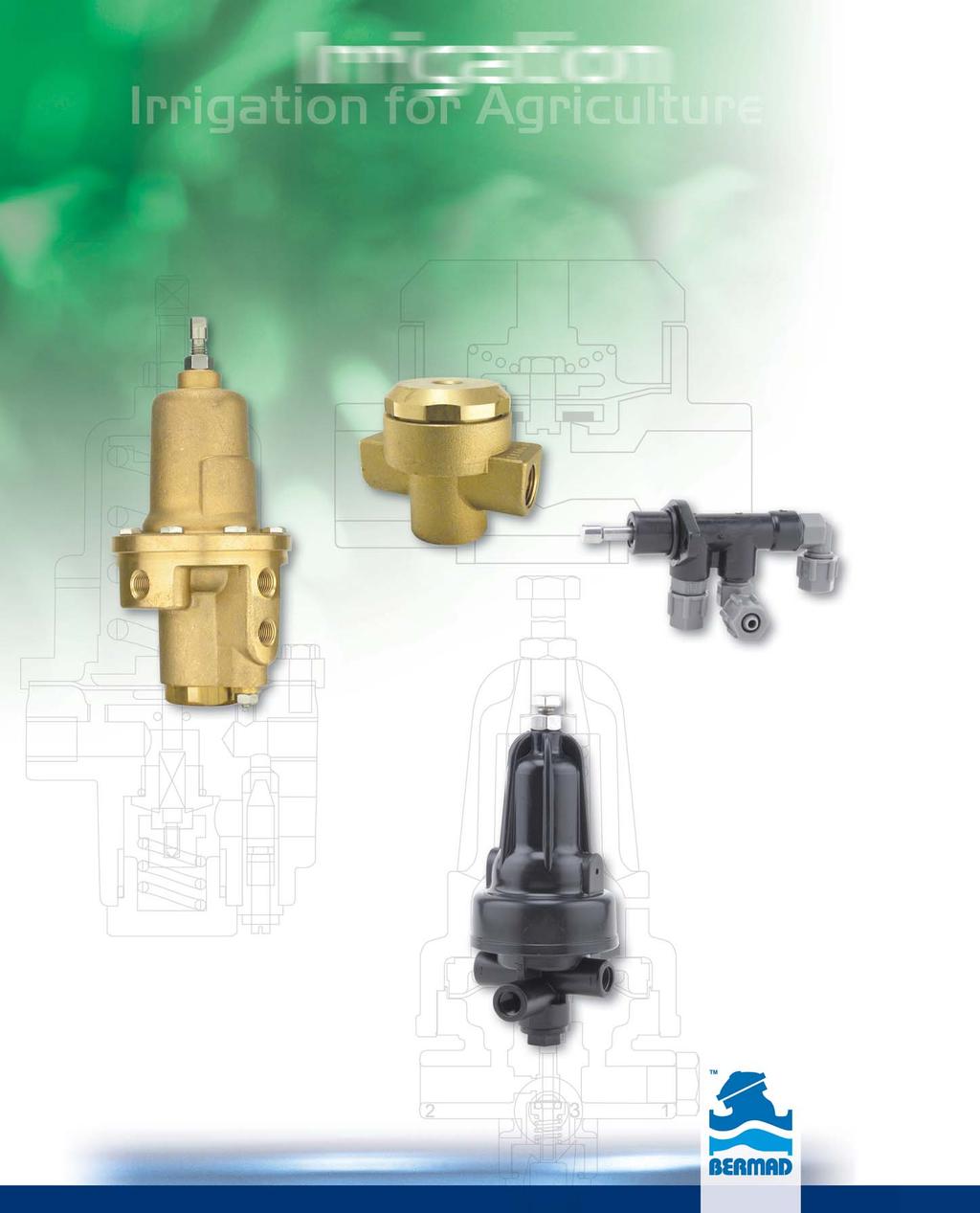
85 Accessories Accessories
86 Accessories

87 Accessories Mini Pilots Positioning 3-ay Pilot Valve PC-X-P, Plastic PC-X-M, Metal This multi-purpose, direct acting 3-way positioning pilot valve is actuated by a pressure responsive diaphragm, which seeks to reach equilibrium between hydraulic and set spring forces. The pilot directs flow and pressure between its ports: hen sensed pressure is above set point, it connects port 0 to port 3. hen sensed pressure is equal to set point, it blocks connections between all ports. hen sensed pressure is below set point, it connects port 3 with port 2. Relevant pressure is continuously sensed through port 1. Setting Range Table Pressure Spring bar psi G-Blue Orange N-Natural K-Gray Connections 0 - Upstream for reducing, Vent for sustaining 3 - Valve control chamber 2 - Vent for reducing, Upstream for sustaining 1 - Pressure Sensing Pressure Reducing Pilot Valve PC-20-P, Plastic PC-20-M, Metal This pilot integrates all principal functions of a 2-way control circuit into a single assembly. It is a direct acting pilot valve, actuated by a pressure responsive diaphragm, which seeks to reach equilibrium between hydraulic and set spring forces. hen used in a pressure reducing circuit, the pilot modulates closed as downstream pressure rises above set point. An internal restriction acts as an upstream flow restrictor. Setting Range Table Pressure Spring bar psi G-Blue Orange N-Natural K-Gray Connections 1 or 2 - Downstream / Remote sensing 3 - Valve control chamber 4 - Upstream Pressure Sustaining Pilot Valve PC-30-P, Plastic PC-30-M, Metal This is a 2-way direct acting pilot valve, actuated by a pressure responsive diaphragm, which seeks to reach equilibrium between hydraulic and set spring forces. hen used in a pressure relief/sustaining circuit, the pilot modulates open as upstream pressure rises above set point. Setting Range Table Pressure Spring bar psi G-Blue Orange N-Natural Connections 0 - Downstream 1 - Sensing/pressure gauge 2 - Sensing/Pressure gauge 3 - Valve control chamber 4 - Upstream (through internal restriction) 190

88 Accessories Mini Pilots Quick Pressure Relief Pilot Valve PC-3Q-P, Plastic PC-3Q-M, Metal This pilot integrates all principal functions of a 2-ay control circuit in a single assembly. It is a direct acting pilots valve, actuated by a pressure responsive diaphragm, which seeks to reach equilibrium between hydraulic and set spring forces.the pilot opens at upstream pressure rise above set point. An integral restriction acts as an upstream flow restrictor smoothing valve closing and simplifying the control circuit. Setting Range Table Pressure Spring bar psi G-Blue Orange Connections 1 - Upstream 2 - Pluged 3 - Valve control chamber 0 - Downstream Pressure Reducing Servo Pilot Valve PC-S-P, Plastic PC-S-M, Metal This pilot combines all principal functions of a 2-way control circuit with elements of a 3-way control circuit. It is a direct acting pilot valve, actuated by a pressure responsive diaphragm, which seeks to reach equilibrium between hydraulic and set spring forces. A fully balanced trim ensures high accuracy and stability. Setting Range Table Pressure Spring bar psi K-Grey J-Green Connections 0 - Upstream for reducing 1 - Sensing 2 - Downstream for reducing 3 - Valve control chamber Paddle Flow Rate Servo Pilot PC-70-M, Metal PC-70-P, Plastic Paddle ength Table This flow rate pilot combines all principal functions of a 2-way control circuit with elements of a 3-way control circuit. It is a direct acting pilot valve, actuated by a paddle that is positioned within the flow stream. Should demand rise above setting, the dynamic force of the increasing flow moves the paddle, which thereby pushes the pilot trim against the spring force. This causes the main valve to throttle closed, limiting system flow to pilot setting. Setting Range Table Flow Velocity Spring m/s f/s E-Purple Valve size Paddle Paddle Number inch DN ength (mm) ength (inch) eaves 1 1 / / / / /4 2 3R 80R / Connections 1 - Upstream 2 - Downstream 3 - Valve control chamber Valve size Paddle Paddle Number inch DN ength (mm) ength (inch) eaves 4R 100R ½ / / /
89 Accessories Pilots Pressure Reducing Pilot Valves BERMAD Pressure Reducing Pilot Valves are direct acting pilot valves, actuated by a pressure responsive diaphragm, which tends to reach equilibrium with the set spring force. They continuously sense downstream or other pressure, which serves as an operating parameter, and throttle closed as sensed pressure rises above set point, controlling the main valve accordingly. Pressure Reducing Pilot Valve #2PB Fully balanced trim ensures high accuracy and stability. hen used in a pressure reducing circuit, the pilot throttles closed as downstream pressure rises above set point. Setting Range Table Pressure Spring bar psi M N J* * For #2PB-D, differential sensing Connections Z - Upstream A - Valve control chamber C - Downstream F/D - External sensing/pressure gauge Pressure Reducing Pilot Valve with integral needle valve #2 This pilot integrates all principal functions of a 2-way control circuit in a single assembly. An integral needle valve acts as an upstream flow restrictor as well as a closing speed control. Setting Range Table Pressure Spring bar psi * * * ith high pressure setting kit Connections Z - Upstream A - Valve control chamber C - Downstream F/D - External sensing/pressure gauge igh Sensitivity Pressure Reducing Pilot Valve with integral needle valve #82 This high sensitivity direct acting pilot specially suits very low set pressures or level control applications. It integrates all principal functions of a 2-way control circuit in a single assembly. An integral needle valve acts as an upstream flow restrictor as well as a closing speed control. Setting Range Table Pilot Code Meter Feet M M M M Connections Z - Upstream A - Valve control chamber C - Downstream Sensing - For altitude control still point at reservoir bottom For pressure reducing to valve downstream 192
90 Accessories Pilots Pressure Sustaining Pilot Valves BERMAD Pressure Sustaining Pilot Valves are direct acting pilot valves, actuated by a pressure responsive diaphragm, which tends to reach equilibrium with the set spring force. They continuously sense upstream or other pressure, which serves as an operating parameter, and modulate open as sensed pressure rises above set point, controlling the main valve accordingly. Pressure Sustaining Pilot Valve #3PB hen used in a pressure sustaining circuit, the pilot modulates open as upstream pressure rises above set point. Setting Range Table Pressure Spring bar psi M N J* * For #3PB-D, differential sensing Connections 1 - Remote sensing or pressure gauge 2 - Valve control chamber 3 - Remote sensing or pressure gauge 4 - Downstream Note: Upstream pressure is connected to valve control chamber via a restriction. Pressure Sustaining Pilot Valve with integral needle valve #3 This pilot integrates all principal functions of a 2-way control circuit in a single assembly. An integral needle valve acts as an upstream flow restrictor as well as a closing speed control. Setting Range Table Connections Pressure Z - Upstream Spring bar psi A - Valve control chamber C - Downstream F/D - External sensing/pressure gauge 16* * * ith high pressure setting kit igh Sensitivity Pressure Sustaining Pilot Valve with integral needle valve #83 This high sensitivity direct acting pilot specially suits very low set pressures or level sustaining applications. It integrates all principal functions of a 2-way control circuit in a single assembly. An integral needle valve acts as an upstream flow restrictor as well as a closing speed control. Setting Range Table Pilot Code Meter Feet M M M M Connections Z - Upstream A - Valve control chamber C - Downstream Sensing - For level sustaining - still point at reservoir bottom For pressure sustaining - valve upstream 193
91 Accessories Pilots Positioning Pilot Valves BERMAD multi-purpose, direct acting, 3-way positioning pilot valves are actuated by a pressure responsive diaphragm, which tends to reach equilibrium with the set spring force. The pilot directs flow and pressure between its ports: hen sensed pressure is above set point, it connects port C to port 0. hen sensed pressure is equal to set point, it blocks connections between all ports. hen sensed pressure is below set point, it connects port C with ports A and Z. An integral needle valve restricts flow through port Z. Positioning Pilot Valve #X Suitable for Pressure Reducing Valves, Pressure Sustaining Valves, and Pressure Reducing & Sustaining Valves, the Positioning Pilot provides accurate and stable regulation, fully opening or closing the valve upon sensed pressure discrepancy from setting. The pilot can also serve as an Adjustable ydraulic Relay (N.O. or N.C.) or Automatic Regulation Override (feature 09). Setting Range Table Pressure Spring bar psi Connections 0 - Upstream for reducing, vent for sustaining C - Valve control chamber A/Z - Vent for reducing, upstream for sustaining F/D - Sensing/pressure gauge 194

 Positioning Pilot Valve #8 This Altitude (igh Sensitivity) Positioning Pilot senses reservoir level and controls the valve to shut at the preset reservoir high level, and")
92 Accessories Pilots Altitude Pilots and evel control Float Valves Altitude pilots and evel control float Valves enable external installation of the main valve, eliminating installation and maintenance problems associated with mechanical float valves installed in the reservoir. A wide selection of altitude and float pilots makes BERMAD Float Control Valves the right solution wherever level control is required. Altitude (igh Sensitivity) Positioning Pilot Valve #8 This Altitude (igh Sensitivity) Positioning Pilot senses reservoir level and controls the valve to shut at the preset reservoir high level, and to fully open in response to an approximately one-meter (three-foot) level drop. The pilot is also suitable for Pressure Reducing Valves with very low setting requirements. Setting Range Table Pilot Code Meter Feet M M M M Connections 0 - Upstream C - Valve control chamber A - Vent (Z plugged) Z - Vent through needle valve (A plugged) Sensing - Still point at reservoir bottom 4-ay Bi-evel Vertical Float Float #66 This 4-ay, adjustable, last position Bi-evel Vertical Float, is actuated by the float s sliding along the rod assembly either pulling it down or pushing it up, switching the float pilot position. hen the float is between the adjustable high and low level stoppers, the main valve remains in its last position. The float pilot directs flow and pressure between its ports: hen the float pushes the upper stopper up, it connects port P to C1 and port C2 to V. hen the float pulls the lower stopper down, it connects port P to C2 and port C1 to V. The extendable rod is to be balanced by counterweights installed on the lever system according to rod length and system pressure. Notes: Minimum level differential: 15 cm (6 ) Maximum level differential: 54 cm (21 ) Each extension rod adds 56 cm (22 ), one extension rod supplied Extra counterweight required if second extension rod used Float hydraulic connections: 3 tubes size 3/8 igh level C1 Connections 60 ow level V C2 P Port Reservoir inlet Reservoir outlet C1 Upper control chamber ower control chamber C2* ower control chamber (or plugged) Upper control chamber P Upstream pressure Upstream pressure V Vent Vent * For double chambered valve only, plugged in single chamber applications 195
93 Accessories Solenoids Solenoid Selection Guide The automation design is an integral part of the irrigation project design file. In order to help in the selection process of the most suitable solenoids for a given project, several questions need to be answered. Following the chart below, will guide you to the desired solenoid model. Please check selected solenoid specifications in the following pages, to confirm its suitability to the project conditions. Please refer to the following questions for best navigation: Operating Current: Alternating Current (AC) or Direct Current (DC) Solenoid ogic: 2-ay or 3-ay Actuator Type: Continuous Current or atching Solenoid Normal Position: Normally Open or Normally Closed Controller Requirements: Two ires or Three ires AC or DC AC (24V Only) DC Continuous atching 2 ires or 3 ires 2 ires 3 ires 2-ay 3-ay 2-ay 3-ay 2-ay 3-ay 3-ay N.C. Only N.C. N.O. N.C. Only N.C. N.O. S R- 24V/AC-NC S R- 24V/AC-NC S R- 24V/AC-NO S V/DC-NC S V/DC-NO S V/DC S V/DC-BB S D- 24V/AC-NC S D- 24V/AC-NC S D- 24V/AC-NO S V/DC-N S V/DC-NO S V/DC-BB S R- 24V/AC-NC S D- 24V/AC-NO S V/DC-NC S V/DC-NO S V/DC-BB S R- 24V/AC-NO S V/DC-NC S V/DC-NO Notes: To get a 3-way controlled N.C. main valve, use a N.O. 3-way solenoid and vice versa. S-400 models include bigger orifice diameter than S-390, which means quicker action. The S-982 and S-985 actuators are isolated from the water. Actuators with the suffix 'R' are suitable to areas with high lightning's probability Calculate wires cross section in accordance to: System pressure conditions Solenoids consumption, quantity & distance 196

94 Accessories Solenoids Solenoids BERMAD Continuous Current Solenoids are specially designed for reliable long life service in irrigation systems. They excel in their low power consumption and low sensitivity to dirt and voltage variations and are compliant with all Continuous Current Controllers on the market. 2-ay Solenoid Actuator S The BERMAD S is a compact 2-ay, Normally Closed, Solenoid Actuator. It is applicable directly to the valve cover or with a 2-way base that enables combining the S in a variety of 2-way control circuits. Electrical Data Actuator Type Cable Color Power (att) Current (Amp) Coil Resistance Inrush old ohm@20 C; 68 F S VAC-R Red/Red S VAC-D Red/Orange * S VDC Black/Black S VDC Blue/Blue * Coil resistance in this coil can not be measured 3-ay Solenoid S The BERMAD S is a compact 3-ay Solenoid. It can control valves independently or in combination with other control circuit accessories. The hydraulic base features a manual override and consists of a bracket for attaching to the valve or to a solenoid manifold. Electrical Data Actuator Type Cable Color Coil Current (Amp) Power Resistance (att) ohm@20 C; Inrush old 68 F S VAC-D NO Red/Orange S VAC-D NC Orange/Blue * S VAC-R NO Red/Red S VDC NO & NC Black/Black S VDC NO & NC Blue/Blue * Coil resistance in this coil can not be measured Connections: N.O.: Actuactor Port - Pressure 1- Vent 2- Valve Control Chamber N.C.: Actuactor Port - Vent 1- Pressure 2- Valve Control Chamber 3-ay Solenoid with ydraulic Base S The BERMAD S-400-D-3-BB is a compact 3-ay Solenoid Pilot Valve that can control valves independently or in combination with other control circuit accessories. The hydraulic base features a manual override and consists of a bracket for attaching to the valve or to a solenoid manifold. Electrical Data Actuator Type Cable Color Power (att) Current (Amp) Inrush old Coil Resistance ohm@20 C; 68 F S400-24VAC-D-NO Red/Blue * S400-24VAC-D-NC Red/Blue * S400-24VDC-NO Black/Black S400-12VDC-NO Blue/Blue * Coil resistance in this coil can not be measured Connections: N.O.: 1- Vent 2- Valve Control Chamber 3- Pressure N.C.: 1- Pressure 2- Valve Control Chamber 3- Vent 197


95 Accessories Solenoids 3-ay Solenoid Valve, Direct Acting with Isolating Membrane Burkert 330 This direct acting 3-ay Solenoid Valve is actuated by a pivoted armature. Its design includes a membrane that hermetically isolates the solenoid actuator from the fluid, making it less sensitive to abrasive or contaminated fluid than a plunger actuated solenoid. This solenoid valve provides best performance with maximum reliability and a long service life, even in seawater applications. The epoxy encapsulation efficiently dissipates heat, to suit continuous duty applications. The Burkert Model 330 can also be used as a 2-ay Solenoid. Electrical data: Power consumption: (ac): 30 VA, inrush; 15 VA (8), holding (dc): 8 Circuit functions 2-ay Normally Closed 2-ay Normally Open 2-ay Normally Closed 2-ay Normally Open 3-ay Solenoid Valve, Direct Acting Plunger Actuated Burkert 6014 This direct acting, compact 3-ay Solenoid Valve is plunger actuated. It does not require a minimum operating pressure and is not affected by the mounting position. Its structure ensures long life and durability. The epoxy encapsulation efficiently dissipates heat, to suit continuous duty applications. The Burkert Model 6014 can also be used as a 2-ay Solenoid. Electrical data: Power consumption: (ac): 24 VA, inrush; 17 VA (8), holding (dc): 8 Circuit functions 2-ay Normally Closed 2-ay Normally Open 2-ay Solenoid Valve, Servo-Assisted Diaphragm Actuated Burkert 281 This is a diaphragm actuated, servo-assisted, pilot operated 2-ay Solenoid Valve. It is available in two versions: Normally Closed (Model: 5281A) Normally Open (Model: 0281B) Electrical data: Power consumption: (ac): 21 VA, inrush; 12 VA (8), holding (dc): 8 Circuit functions 2-ay Normally Closed 2-ay Normally Open 198


96 Accessories atching Solenoids atching Solenoids BERMAD atching Solenoids are specially designed for reliable long life service in irrigation systems controlled by Battery Operated Controllers. The atching Solenoids consume power only when switching positions, using a very short electric impulse. This prolongs life of batteries and enables solar recharging. Magnetic atch Solenoid Actuator, 2-ay, 9VDC atch, 2- eads S The BERMAD Model S is a compact 2-ay atching Solenoid Actuator. It is applicable directly to the valve cover or with a 2-way base that enables combining it in variety of 2-way control circuits. Electrical Data: Voltage Range: 6-20 VDC Coil Resistance: 6Ω Coil Inductance: 90 m Pulse idth: msec. Required Capacitor: 4700µF Operation Modes (electrical connections): +Red & -Black: atch Position +Black & -Red: Released Position Magnetic atch Solenoid with ydraulic Base 3-ay, 9VDC atch, 2- eads S The BERMAD Model S can control valves independently or in combination with other control circuit accessories. The hydraulic base features a manual override and consists of a bracket for attaching to the valve or to a solenoid manifold. Electrical Data: Voltage Range: 9-40 VDC Coil Resistance: 6Ω Coil Inductance: 90 m Pulse idth: msec Required Capacitor: 4700µF Operation Modes (electrical connentions): +Red & -Black: Solenoid vents +Black & - Red: Solenoid pressurizes Connections: 1- Vent 2- Valve Control Chamber 3- Pressure Pressure & Flow Data: Operating Pressure Range: 0-10 bar Base Orifice Diameter: 2.2 mm Base Flow Factor: Kv = bar ΔP; Cv= 0.14 psi ΔP 199

97 Accessories atching Solenoids Dry Magnetic atch Solenoid with Isolating Membrane & ydraulic Base 3-ay, 12VDC atch, 2- eads S The BERMAD Model S actuator is neutralized from water damage by a membrane, which hermetically isolates it from the water. It can control valves independently or in combination with other control circuit accessories. The hydraulic base features a manual override and consists of a bracket for attaching to the valve or to a solenoid manifold. Electrical Data: Voltage Range: VDC Coil Resistance: 4.2Ω Pulse idth: msec. Required Capacitor: 4700µF Operation Modes (electrical connections): + Red & - Black: Solenoid vents + Black & - Red: Solenoid pressurizes Connections: 1- Vent 2- Valve Control Chamber 3- Pressure Pressure & Flow Data: Operating Pressure Range: 0-10 bar Base Orifice Diameter: 2.2 mm Base Flow Factor: Pressure port Kv = 0.12 m 3 1 bar ΔP Cv = 0.14 psi ΔP Exhaust port Kv = 0.14 m 3 1 bar ΔP Cv = 0.16 psi ΔP Dry Magnetic atch Solenoid with Isolating Membrane & ydraulic Base 3-ay, 12VDC atch, 3- eads S The BERMAD Model S actuator is neutralized from water damage by a membrane, which hermetically isolates it from the water. It can control valves independently or in combination with other control circuit accessories. The hydraulic base features a manual override and consists of a bracket for attaching to the valve or to a solenoid manifold. Electrical Data: Voltage Range: VDC Coil Resistance: 2 Coils - 4.2Ω On; 7.5Ω Off Pulse idth: msec. Required Capacitor: 4700µF Operation Modes (electrical connections): + hite: Fixed Common - Red: Solenoid vents - Black: Solenoid pressurizes Connections: 1- Vent 2- Valve Control Chamber 3- Pressure Pressure & Flow Data: Operating Pressure Range: 0-10 bar Base Orifice Diameter: 2.2 mm Base Flow Factor: Pressure port Kv = 0.12 m 3 1 bar ΔP Cv = 0.14 psi ΔP Exhaust port Kv = 0.14 m 3 1 bar ΔP Cv = 0.16 psi ΔP Solenoid Valve for Remote Terminal Unit (RTU) BERMAD s Solenoid Valve for Remote Terminal Unit (RTU) is a solenoid pilot valve controller used in remote control irrigation via radio or cable. It is a battery operated, self-contained unit, suitable for use in irrigation applications with a master radio control system. Note: RTU units can be purchased only through Motorola irrigation control department. For further details please contact: IRRInet.marketing@motorola.com 200


98 Accessories Accessories & Components ydraulic Relay Valve (RV) 50-P, Plastic 50-M, Metal This 2-way, single chamber, ydraulic Relay Valve is a hydraulically operated, diaphragm actuated control valve that shuts off in response to pressure applied to its control chamber, or opens fully upon venting of that pressure. Technical Data Pressure rating: Metal - 25bar; 350 psi Plastic -10 bar; 145 psi Flow factor: Metal - Kv=1.3; Cv=1.5 Connections Metal - 2- Inlet; 1- Outlet Plastic - 1- Inlet; 2- Outlet Shuttle Valve 50-X-P, Plastic 50-X-M, Metal These pressure selector Shuttle Valves have been designed to automatically direct the higher of two pressure sources into a control or sensing chamber. Each source is connected to its own port. The higher pressure creates a superior force that moves the inner plug to seal the counter port, allowing water from the higher pressure source to flow through the common port. Technical Data Pressure rating: Metal - 25bar; 350 psi Plastic -10 bar; 145 psi 3-ay ydraulic Relay Valve (3-RV) 54-PZ, Galit 54-M - Metal The 3-ay, single chamber, ydraulic Relay is a hydraulically operated, diaphragm actuated pilot valve that in response to pressure applied to its control chamber, directs flow and pressure between its ports. It can be used either to relay and accelerate a signal (N.O.), or to reverse and accelerate a signal (N.C.). The Model 54-PZ, Galit also features Manual Override. Connections Port 54-M, N.O.* 54-M, N.C.** 1 Upstream pressure Vent 2 Control chamber Control chamber 0 Vent Upstream pressure U Command Command * ith top spring - special order. ** ith bottom spring - standard. 1 Command Command 2 Vent Upstream pressure 3 Upstream pressure Vent 4 Control chamber Control chamber Technical Data Pressure rating: 10 bar; 145 psi Minimum operating pressure: 0.5 bar; 7 psi Orifice: 5.8 mm; 1 /4 Ports: 1 /8 BSP Female Thread Technical Data Pressure rating: 25 bar; 350 psi Min. operating pressure: 0.8 bar; 12 psi Flow factor: Closing: 0 to 2 & 1 to 2: Kv=1.2; Cv=1.4 Opening: 2 to 1 & 2 to 0: Kv=1.0; Cv=1.2 Connections Anti-Topographic Springs 54-PZ, N.C. 54-PZ, N.O. Spring Port 54-PZ, N.C. 54-PZ, N.C 54-PZ, 54-PZ, N.C. N.C. 54-PZ, 54-PZ, N.C. N.O. Color Yellow 5-10 m 5-10 m Green m m hite m 5-20 m Red m m Data refers to elevation differential along the control tube 201


99 Accessories Accessories & Components AMV Shut-Off Pilot 3-SOP This 3-ay Shut-Off Pilot Valve is a spring-return, flap actuated pilot valve that in response to pushing a spool against a spring, directs pressure and flow between its ports: In Set Position the 3-SOP spool is pushed closed, thereby hydraulically connecting ports C and V. In Normal Position the 3 SOP spool is returned by the spring action, hydraulically connecting ports P and C. By manually turning the AMV setting knob, the flap is actuated to push the spool. After delivering the preset quantity of water, the flap slips into a groove in the turning control head mechanism, allowing the spool to return to Normal Position. Connections: P - Upstream C - AMV Control Chamber V - Vent AMV Sequential Shut-Off Pilot 5-SOP This 5-ay Shut-Off Pilot Valve directs pressure and flow between its ports: In Set Position the 5-SOP spool is pushed closed, thereby hydraulically connecting ports P to C2 and C1 to V1. In Normal Position the 5-SOP spool is returned by the spring action, hydraulically connecting ports P to C1 and C2 to V2. Connections: P - Upstream C1 - AMV Control Chamber C2 - Next AMV (Plugged for last AMV) V1 - Previous AMV ( Vent for first AMV) V2 - Vent AMV Shut-Off Pilot with Pump Shut-Off Electrical Switch 3-SOP-S This 3-ay Shut-off Pilot Valve directs pressure and flow between its ports: In Set Position the 3-SOP-S spool is pushed closed, thereby hydraulically connecting ports C1 to V1. In Normal Position the 3-SOP-S spool is returned by the spring action, hydraulically connecting port P to C1. The spool activates the electric Change-Over Switch, which turns off the system s pump after delivery of the preset quantity of water. Connections: P - Upstream C1 - AMV Control Chamber V1 -Vent C2 -Plugged Switch Data: Change Over 5-250V Electrical Connections N.O. or N.C. 202

 In-ine Filter These self-flushing In-ine Filters are used for filtration of control fluid of medium and potable water quality.")


100 Accessories Acessories & Components Needle Valve This adjustable restriction Needle Valve is used for controlling opening or closing speed on various control loops. Needle valve types: 5º - for up to 4 ; DN100 valves 15º - for 6 ; DN150 and larger valves One-ay Flow Control This device combines an adjustable restriction needle valve one way, and free flow the opposite way. It is used for controlling opening or closing speeds and stabilizing main valve operation. Technical Data Pressure rating: 40 bar; 600 psi Flow factor: Kv=0.85; Cv=1.0 (in unrestricted flow direction) In-ine Filter These self-flushing In-ine Filters are used for filtration of control fluid of medium and potable water quality. The flowing fluid continuously flushes the filter element. Technical Data Filter element: 400 micron; 40 mesh Threads: Metal - 1 /4, 3 /8 & 1 /2 NPT; Plastic - 1 /4 NPT Male X 1 /8 NPT Female Y Strainer The "Y" Strainer is used for filtration of control fluid with standard potable water quality and standard maintenance. Technical Data Filter element: 500 micron; 35 mesh Ports: 1 /4, 3 /8 & 1 /2 NPT, 1 BSP arge Control Filter The arge Control Filter is used for filtration of dirty control fluid that would quickly block a normal filter element. This larger filter increases both the reliability of the control valve system and the time required between maintenance, while minimizing faulty operation. Technical Data Filter element: Disks 250 micron; 60 mesh Ports: 3 /8 NPT 203


101 Accessories Accessories Components 2-ay Ball Valve This Ball Valve provides quick and easy on/off manual control for isolating, manual release, and draining. Technical Data Pressure rating: 40 bar; 600 psi - 1 /4 to 3 /4 35 bar; 500 psi - 1 to 2 Ports: 1 /4, 3 /8 & 1 /2 NPT 3 /4, 1, 1 1 /2 & 2 BSP 3-ay Ball Valve This 3-ay Ball Valve is used as a pilot providing quick and easy, 2-position on/off manual control. Technical Data Pressure rating: 27.5 bar; 400 psi Ports: 1 /4, 3 /8 & 1 /2 NPT Manometer Ball Valve This vented 2-ay Ball Valve provides quick and easy manual isolating and venting of either pressure gauges or any other pressurized control loop components. Technical Data Pressure rating: 16 bar; 230 psi Ports: 1 /8, 1 /4 & 3 /8 NPT Check Valve These spring loaded, non-return valves provide free flow in one direction and prevent flow in the opposite direction. They can be installed in any orientation. Technical Data Pressure rating: 20.5 bar; 300 psi Ports: 1 /4, 3 /8 & 1 /2 NPT 3 /4, 1 & 1 1 /2 BSP 204


102 Accessories System Components Orifice Plate Assembly hen an Orifice Plate Assembly is used as an integral part of a flow control valve control circuit, it provides the differential pressure (P) to power the flow control pilot. The opening and closing of the pilot causes the flow control valve to throttle accordingly. Total head loss across the valve is reduced by locating sensing ports close to the orifice plate, to sense downstream pressure before it recovers. The orifice plate s internal diameter is calculated and machined according to valve size and required flow limitation. Dimensions.P. port.p. port 1 /8 NPT d D XZ Orifice Assembly hen an Orifice Assembly is used as an integral part of a flow control valve control circuit, it provides a Pressure Differential (P) in direct proportion to the flow rate.this P is sensed by the flow control pilot, powering it to open or close. The opening and closing of the pilot causes the flow control valve to throttle accordingly. The orifice s internal diameter is calculated and machined according to valve size and required flow limitation. Dimensions 205

 from highly corrosive")
103 Accessories System Components Pressure Gauge This robust, liquid filled Pressure Gauge is used for heavy duty service where vibration or pulsation of the pressure is liable to cause excessive wear of a dry gauge, or where corrosive ambient conditions or fluid prevail. Technical Data Dial size: 2 1 /2 ; 63 mm Connection: 1 /4 NPT, back or bottom Scales: 0-6, 10, 16, 25 and 40 bar 0-90, 140, 230, 350 and 600 psi Accuracy: ± 1.6% of full scale dial Pressure Sensing Separation Diaphragm Model 35d This device is used to isolate and protect the pressure sensing chambers of pilots (and pressure gauges) from highly corrosive fluids, high viscosity fluids, or fluids with suspended solids. It has two chambers separated by a diaphragm. The sensed system pressure is introduced into one chamber, applying force to the diaphragm that transmits it to the second chamber. The second chamber and the pilot sensing chamber are connected and are both filled with a non-aggressive, stable fluid. Technical Data Pressure rating: 25 bar; 350 psi Ports: 1 /4 NPT Air venting ports: 1 /8 NPT 206

104 Accessories System Components Strainer Model 70F The BERMAD 70F Strainer is designed to remove foreign matter such as stones, sticks, etc. from the pipeline. It is recommended to install the Strainer upstream from control valves, flow meters and other system appliances. igh Pressure Strainer Model 80F is also available. close to the orifice plate, to sense downstream pressure before it recovers. The orifice plate s internal diameter is calculated and machined according to valve size and required flow limitation. Dimensions & eight Technical Data Patterns: Y (globe) & angle Size Range: mm; 1 1 /2-20 End Connections (Pressure Ratings): Flanged: ISO PN16, PN25; ANSI Class 150, 300 Threaded: BSP or NPT Others: Available on request Standard Materials: Body: Ductile Iron Cover: Steel Seals: NBR Coating: Polyester Powder, RA 6017 (Green) Basket ole Diameter (mm) Stainless Steel 304 (Standard) Stainless Steel 316 (Optional) Flow Chart 207
i n f b e r m a d. c o m w w w. b e r m a d. c o m
 asic Valve IR-900-M ydrometer with Magnetic Drive The ERMAD Model IR-900-M is a unique product integrating both a vertical turbine oltman-type water meter and a diaphragm actuated hydraulic control valve.
BERMAD Irrigation. Automatic Metering Valve (AMV) 900-D Series. Basic Valve ??????? IR-900-D.
 900-D Series. Basic Valve ??????? IR-900-D.") asic Valve??????? I-9-D Automatic Metering Valve (AMV) The EMAD Model I-9-D is a unique product integrating both a vertical turbine oltman-type water meter and a pilot operated, diaphragm actuated control
asic Valve??????? I-9-D Automatic Metering Valve (AMV) The EMAD Model I-9-D is a unique product integrating both a vertical turbine oltman-type water meter and a pilot operated, diaphragm actuated control
BERMAD Irrigation. IR-100 hyflow Basic Valve. Basic Valve.
 Basic Valve IR- Yflow Basic Valve Te BERMAD basic Model IR- Yflow diapragm actuated, ydraulically operated valve is at te leading edge of control valve design. It combines simple and reliable construction
BERMAD Waterworks. Level Control Valve with Altitude Pilot. 700 Series. Model X. Features and Benefits. Major Additional Features
 Level Control Valve with Altitude Pilot High level reservoirs & water towers Energy cost critical systems Systems with poor water quality Inherent refreshing Level sustaining at reservoir outlet The Level
NEW. BERMAD Irrigation 100 Series - High Performance Valves. Water Control Solutions
 NE BERMAD Irrigation ig Performance Valves ater Control Solutions 100 Series Yflow ig Performance Plastic ydraulic Control Valves Features and Benefits Durable industrial grade valve design and construction
CAST IRON VALVES FLOAT VALVE
 CAST IRON VALVES FLOAT VALVE NETAFIM CAST IRON VALVES FLOAT VALVE INLINE 25-400MM ANGLE 50-100MM SPECIFICATIONS Manufactured to ISO 9001 Available Valve sizes INLINE Flanged 50mm to 600mm & Threaded 19mm
700 SIGMA SERIES ENGINEERING DATA
 700 SIGMA SERIES ENGINEERING DATA CONTENT 700 SIGMA EN/ES 2-8 700 SIGMA EN/ES 2 Exploded View 3 Material Specifications 4 Principle of Operation 5 Plug Options 6 Cavitation 7 Cavitation Cage 8 700 SIGMA
BERMAD Waterworks. Pressure Reducing Valve. 700 Series. Model 720. Features and Benefits. Major Additional Features
 Pressure Reducing Valve Flow and leakage reduction Cavitation damage protection Throttling noise reduction Burst protection System maintenance savings The Pressure Reducing Valve is a hydraulically operated,
BERMAD Waterworks. Pressure-Reducing Valve. 700 Series. Model 720. Features and Benefits. Major Additional Features
 Pressure-Reducing Valve Flow and leakage reduction Cavitation damage protection Throttling noise reduction Burst protection System maintenance savings The Pressure-Reducing Valve is a hydraulically-operated,
300 Series. Automatic Hydraulic Control Valves
 Automatic Hydraulic Control Valves AVFI Pty Ltd 54 Enterprise Drive Bundoora Vic 3083 p: 03 8467 0000 f: 03 8467 0099 e: avfi@avfi.com.au w: www.avfi.com.au 300 Series General 300 SERIES Automatic Hydraulic
Bermad Model:
 Bermad Model: 405-02 Manually Operated Hydraulic Valve INSTALLATION OPERATION MAINTENANCE Application Engineering BERMAD 1. Safety First BERMAD believes that the safety of personnel working with and around
Pressure Regulating Valves. Models 44, 77 & 68 PS\ UL. Pressure Relief Valve. Dorot Fire Protection Division. Certification & compliance by design
 Fire Protection Div. Dorot Fire Protection Division Models, & 6 PS\ UL Pressure Relief Valve Certification & compliance by design -PS\UL ANSI FCI - Class VI seat leakage class Fire tested to EN ISO 6-:6
BEFORE SALES AFTER SALES
 TALIS FP RANGE TALIS FP RANGE TALIS is a leading global provider of premium valves, hydrants and control solutions for water flow control and Fire Protection Systems With a varied range of products, Talis
Flow Sensors & Hydrometers Specification Sheet
 Baseline Flow s and Hydrometers Baseline s smart flow sensors and hydrometers are two-wire ready flow measurement and control devices that are pre-programmed with the correct K and Offset values. In addition,
AWWA C504 COMPLIANT VALVES FROM 3 THRU 108
 AWWA C504 COMPLIANT VALVES FROM 3 THRU 108 PO Box 411 Berwick PA 18603 800-247-VALV www.crispinvalve.com 500 SERIES: Sizes 3-20 Available The K-Flo 500 Series is a heavy-duty resilient seated butterfly
HYDRAULIC CONTROL VALVES
 HYDRAULIC CONTROL VALVES INC. VALVES, INC HYDRAULIC CONTROL VALVES WORKING PRINCIPALS It is automatic hydraulic control valve designed for make desired modulation processes in main valve network line as
TECHNICAL DATA 3 MODEL G-3000 DRY VALVE RISER ASSEMBLY
 Page 1 of 13 1. DESCRIPTION The Viking 3 Model G-3000 Dry Valve Riser Assembly is equipped with a small profile, light weight, pilot operated valve that is used to separate the water supply from the dry
TECHNICAL DATA. Q= Cv S
 Page 1 of 13 1. DESCRIPTION The Viking 4 inch Model G-4000 Dry Valve Riser Assembly consists of a small profile, light weight, pilot operated valve that is used to separate the water supply from the dry
TECHNICAL DATA Q = C. v P S. 2 Model G-2000 Dry valve. Page 1 of 13
 Page 1 of 13 1. Description The Viking 2 Model G-2000 Dry Valve Riser Assembly consists of a small profile, light weight, pilot operated valve that is used to separate the water supply from the dry sprinkler
TECHNICAL DATA. Q = C v P S
 Page 1 of 13 1. DESCRIPTION The Viking 6 Model G-6000 Dry Valve Riser Assembly consists of a small profile, light weight, pilot operated valve that is used to separate the water supply from the dry sprinkler
Ø248 Ø Series. R 2.00 R 2 Hydraulic Control Valves R 3 R 6 SEE "SEAT DE T DETAIL NO. 2" CONTROL VALVES
 Ø290 Ø248 Ø240 RAM Ø201 400 Series R 2.00 R 2 Hydraulic Control Valves R 3 G 50 92 30 R 6 SEE "SEAT DE T DETAIL NO. 2" Ø290 Ø248 Ø240 Ø201 30 i n d e x How To Order R 2.00 R 2 2 Company profile 4 Hydraulic
Slam Shut Valves SCN
 Slam Shut Valves SCN SCN > Slam shut valves Introduction SCN is a compact safety device (SAV) which quickly intercept gas flow whenever the pressure under monitoring reaches a pre-set limits, or whenever
BERMAD Waterworks. Level Control Valve with Bi-Level Vertical Float. 700 Series Model B. Features and Benefits. Major Additional Features
 Level ontrol Valve with i-level Vertical Float Reservoir filling Very low supply-pressure Low noise generation Energy cost-critical systems Systems with poor water quality Reservoir outlet Distribution
TECHNICAL DATA. Pressure Regulation 531a. April 24, 2009
 April 24, 29 Pressure Regulation 531a 1. DESCRIPTION The Viking Regulating Valve is a direct-acting, single-seated, spring-loaded diaphragm valve. When installed as a pilot regulating valve on a Viking
safety Shut-Off Valve HON 721
 safety Shut-Off Valve HON 7 product information serving the gas industry worldwide safety shut-off valve HON 7 safety shut-off valve HON 7 Application, Characteristics, Technical Data Application safety
FILTER BYPASS CONTROL
 Differential Control Valve Series 110 The Series 110 Differential Control Valve is designed to accurately control the pressure difference between any two points. In some systems this means the valve remains
End Connection. Thread x Thread N/A N/A N/A N/A Flange x Flange N/A
 Worldwide Contacts www.tyco-fire.com Model RV-1 Pressure Relief Valve, Pilot-Operated, Globe and Angle Body Styles General Description Valves, through inch (DN50 through DN00), are factory assembled and
Combination Air Valve
 Combination Air Valve For Sewage and Wastewater Model C50 Installation, Operation and Maintenance Manual (IOM) Table of Contents General... Page 2 Safety... Page 2 Operational Data... Page 3 Materials
Bermad Pressure Reducing. Model: 42T
 Bermad Pressure Reducing Pilot Operated Pressure Control Valve Model: 42T Installation Operation Maintenance Manual (IOM) REV. 27.7.17 Page 1 of 12 Safety First BERMAD believes that the safety of personnel
AIR AND VACUUM VALVES
 MINING DIVISION AIR AND VACUUM VALVES FOR HIGH FLOW K-6NS SERIES DESCRIPTION The K-6NS Series Air and Vacuum Valve discharges air during the filling or charging of the system and admits air into the system
BERMAD Waterworks. Level Control Valve. with Bi-Level Vertical Float. 700 Series. Major Additional Features. Features and Benefits.
 Level Control Valve with Bi-Level Vertical Float Reservoir filling Very low supply pressure Low noise generation Energy cost critical systems Systems with poor water quality Reservoir outlet Distribution
Pressure reducing valves Index
 Index General information page Introduction 506 General introduction 507 for a steam plant 509 Product information BSP thread page Brass 510 ; BSP female thread 511 ; BSP male thread 513 Stainless steel
TECHNICAL ACCESSORIES
 A.R.I. VALVES S-050P AIR PLASTIC RELEASE 16 BAR Automatic Component A.R.I patent, Rolling Seal Mechanism: Dramatically reduces the possibility of obstruction by debris. Discharges high air flow rates upto
TECHNICAL DATA. Page 1 of 12
 Page 1 of 12 1. DESCRIPTION The Viking Regulating Valve is a direct-acting, single-seated, spring-loaded diaphragm valve. When installed as a pilot regulating valve on a Viking Model H or J Flow Control
BACK PRESSURE / SUSTAINING
 In many liquid piping systems, it is vital that line pressure is maintained within relatively narrow limits. This is the function of the 108 Pressure Relief / Back Pressure Series of the OCV control valves.
Model: 43T. Bermad Pressure Relief Valve
 Model: 43T Bermad Pressure Relief Valve Installation Operation Maintenance Manual () Rev.C1_01.08.17 Page 1 of 10 Safety First BERMAD believes that the safety of personnel working with and around our equipment
DN300 DN2000 C Plunger Valve
 ל DN300 DN2000 C Plunger Valve P.O.B 46 MOSHAV SHTULA WESTERN GALILEE 2286500 Tl. +972-(0)77-6656101, Fax. +972-(0)77-6656196 Website: www.saisanketvalves.com www.saisanket.com email: saisanket@saisanket.com
BERMAD Waterworks. Combination Air Valve. Air Valves Series. Typical Applications. Features & Benefits. Additional Features.
 BERMA Waterworks Combination Air Valve Model C7 BERMA C7 is a high quality combination air valve for a variety of water networks and operating conditions. It evacuates air during pipeline filling, allows
TECHNICAL DATA. Q = C v P S
 Preaction 346a 1. Description The 6 Model G-6000P Electric Release Preaction System Riser Assembly can be used as a Single Interlock Preaction System with Electric Release, or as a Double Interlock Preaction
Horizontal Bladder Tanks
 DATA SHEET Horizontal Bladder Tanks Features UL Listed and FM Approved for use with various ANSUL proportioners and foam concentrates 175 psi (12.1 bar) maximum allowable working pressure (design pressure)
VERTICAL BLADDER TANK
 Balanced Pressure Proportioning System Reliable Foam System Requiring Only Water Power Perfect For Tight Spaces UL Listed, ASME, National Board Registered Bladder-UL162 Approved, High Tensile Pressure
Vertical Bladder Tanks
 DATA SHEET Vertical Bladder Tanks Features UL Listed and FM Approved for use with various ANSUL proportioners and foam concentrates 175 psi (12.1 bar) maximum allowable working pressure (design pressure)
HORIZONTAL BLADDER TANK
 Balanced Pressure Proportioning System Reliable Foam System Requiring Only Water Power Perfect For Low Ceilings UL Listed, ASME, National Board Registered Bladder-UL162 Approved, High Tensile Pressure
Description. Functions. Technical data. Applications. Tests. On-Off 2 levels float control valve, closing at high level and opening at low level.
 DN 0 to 1000 - Serie K3 0 On-Off levels float control valve, closing at high level and opening at low level. Functions Prevents overflowing and closes at a constant and adjustable high level. Remains closed
Model MTB-ASME Vertical Bladder Tanks
 DATA SHEET Model MTB-ASME Vertical Bladder Tanks Features n UL Listed for use with various proportioners and foam concentrates n 175 psi (12.1 bar) maximum allowable working pressure (design pressure)
Model MTB-ASME Vertical Bladder Tanks
 DATA SHEET Model MTB-ASME Vertical Bladder Tanks Features n UL Listed for use with various proportioners and foam concentrates n 175 psi (12.1 bar) maximum allowable working pressure (design pressure)
TECHNICAL DATA OBSOLETE
 April 9, 2009 Preaction 326a 1. DESCRIPTION Viking supervised Double-Interlocked Electric/Pneumatic Release Preaction Systems utilizing the Viking G-4000P Deluge Valve. The small profi le, lightweight,
SABERINDO PACIF SABERINDO PACIFIC CIFIC SABERINDO PA. A Tyco International Company
 CIF A Tyco International Company 1 Foam Concentrate CIF 3% AFFF -UL Listed -UL Canada Listed 6% AFFF 6 parts AFFF concentrate to 94 parts water -UL Listed- Foam Liquid -UL Canada Listed 3% FLUOROPROTEIN
TECHNICAL DATA. Q = C v P S
 January 6, 2012 Preaction 333a 1. Description Viking supervised Surefire Preaction Systems Utilize the Viking G-3000P Valve. The small profile, lightweight, pilot-operated Viking G-3000P Valve comes complete
TECHNICAL DATA. Q = C v P S
 January 6, 2012 Preaction 348a 1. Description Viking supervised Surefire Preaction Systems utilize the Viking G-6000P Valve. The small profile, lightweight, pilot operated Viking G-6000P Valve comes complete
Pressure Independent Control Series
 Document No. 155-522 Pressure Independent Control Series Two-Way Cast Iron Flanged Bodies, ANSI 125 and 250 Description Siemens Pressure Independent Control Valves integrate three functions into a single
TECHNICAL DATA. Q = C v P S
 January 6, 2012 Preaction 331a 1. Description Viking supervised Double-Interlocked Electric/Pneumatic Release Preaction Systems utilize the Viking G-3000P Valve. The small profile, lightweight, pilot-operated
BACK PRESSURE / SUSTAINING
 SPECIFICATIONS DIMENSIONS In many liquid piping systems, it is vital that line pressure is maintained within relatively narrow limits. This is the function of the 108 Pressure Relief / Back Pressure Series
Model 1800 PFM Series Regulator. Technical Bulletin
 Model 0 PFM Series Regulator Technical Bulletin Model 0 PFM Series Regulator 0 Elster American Meter The 0 PFM Series regulators are designed to control natural gas, air, nitrogen, carbon dioxide, propane
WaterSource Heat Pump Hose Kit Performance Specification-Summary
 WaterSource Heat Pump Hose Kit Performance Specification-Summary AUTOMATIC & MANUAL BALANCING HOSE KITS Contractor shall provide and install Hays Hose Kits. Each kit, shall include a Hays 2500 Series Mesurflo
Homestead Series 820 AWWA Butterfly Valves
 Homestead Series 820 AWWA Butterfly Valves Dependable Valves for Water & Wastewater Service BODY: The ductile iron body meets or exceeds the design strength requirements of the AWWA C504 standards. Flange
V43 Pressure Actuated Water Regulating Valve
 FANs 125, 121 Product/Technical Bulletin V43 Issue Date 0996 V43 Pressure Actuated Water Regulating Valve The V43 Pressure Actuated Water Regulating Valves are designed to regulate water flow for water-cooled
Rate of Flow Valve Series 120
 SPECIFICATIONS Rate of Flow Valve Series DIMENSIONS The OCV Series 120 Rate of Flow control valve is designed to control or limit flow to a predetermined rate, regardless offl uctuations in downstream
Models 106-RF / 206-RF Rate of Flow Control Valve
 Rate of Valve KEY FEATURES Accurately limits low to a pre-set maximum Easily adjustable low limit Paddle-style oriice plate included Optional oriice plate housing 106-RF Globe Product Overview The 106-RF
VACUUM REGULATORS CONTENTS
 CAD drawing data catalog is available. ACCESSORIES GENERAL CATALOG AIR TREATMENT, AUXILIARY, VACUUM, AND FLUORORESIN PRODUCTS CONTENTS Small Regulators Features 759 Specifications, Order Codes, Flow Rate
Model MTB-ASME Horizontal Bladder Tanks
 DATA SHEET Model MTB-ASME Horizontal Bladder Tanks Features n UL Listed and FM Approved for use with various proportioners and foam concentrates n 175 psi (12.1 bar) maximum allowable working pressure
WATER METERS.
 WATER METERS Can be installed Pulse output with both plug & play system horizontal and vertical No straight Higher sections accuracy required U0 D0 Water engineering High resistance Its operation is based
627 Series Pressure Reducing Regulators
 627 Series Pressure Reducing Regulators Introduction The 627 Series direct-operated pressure reducing regulators (Figure 1) are for low and high-pressure systems. These regulators can be used with natural
TECHNICAL DATA CAUTION
 Page 1 of 12 1. DESCRIPTION The Viking Model C-2 Pilot Pressure Regulating Valve is a direct-acting, single-seated, spring-loaded diaphragm valve. When installed as a pilot regulating valve on a Viking
TECHNICAL DATA. Q = C v P S
 January 6, 2012 Preaction 347a 1. Description Viking supervised Double-Interlocked Electric/Pneumatic Release Preaction Systems utilize the Viking G-6000P Valve. The small profile, lightweight, pilot operated
Aperval Pressure Regulators
 Pressure Regulators Pressure regulators is pilot-controlled pressure regulator for medium and low pressure applications. is normally a fail to open regulator and specificaly will open under the following
SINGLE VALVE WITH LOW-FLOW BYPASS
 CONTROL VALVES Pressure Reducing Valve Sizing Guide Sizing pilot operated reducing valves is not a complicated process. It starts with determining requirements and following these guidelines in valve size
TECHNICAL DATA DELUGE VALVE, MODEL F-1 STRAIGHT THROUGH STYLE
 Page 1 of 10 1. DESCRIPTION The Viking Model F-1 Deluge Valve is a quick opening, differential diaphragm and flood valve with one moving mechanism. The Deluge Valve is used to control water flow in Deluge
TECHNICAL DATA Q= C. Table 1 - Specifications
 September 25, 2013 Pressure Regulation 537a 1. Description The Model B-3 Pilot Operated Pressure Control Valve is a factory assembled unit. The unit consists of a Model J-2 Halar coated Flow Control Valve,
TECHNICAL DATA. Page 1 of 8. model f /2 (dn40) & 2 (dn50)
 & 2 (dn50)") Page 1 of 8 1. DESCRIPTION The Viking Model F-1 Deluge Valve is a quick opening, differential diaphragm, flood valve with one moving mechanism. The Deluge Valve is used to control water flow in Deluge
Page 1 of 8 1. DESCRIPTION The Viking Model F-1 Deluge Valve is a quick opening, differential diaphragm, flood valve with one moving mechanism. The Deluge Valve is used to control water flow in Deluge
Combination Air Valve Model
 Combination Air Valve Model Model C10 /C11 Installation, Operation and Maintenance Manual (IOM) Table of Contents General...Page 2 Safety...Page 2 Operational Data...Page 3 Materials and Connections...Page
DS06D,G Dial Set Pressure Regulating Valve
 DS06D,G Dial Set Pressure Regulating Valve PRODUCT DATA FEATURES APPLICATION Built-in, factory-calibrated outlet pressure adjustment dial. Noncorroding unitized cartridge contains all working parts and
DAV Series. DAV-MH Air Release & Vacuum Break Valves
 DAV-MH Air Release & Vacuum Break Valves ISO 9 AVFI Pty Ltd 4 Enterprise Drive Bundoora Vic 383 p: 3 8467 f: 3 8467 99 e: avfi@avfi.com.au w: www.avfi.com.au General DAV-MH Air Release and Vacuum Break
Pressure Reducing Valve DMV 755
 Pressure Reducing Valve DMV 755 Nominal size DN 10 50 Nominal size 3/8 2 Nominal pressure PN 10 bar Features pressure setting range 1 to 9 bar control valve for reliable reduction of system pressures to
Dual position solenoid valve Type ICSH 25-80
 Data sheet Dual position solenoid valve Type ICSH 25-80 ICSH dual position solenoid valve belongs to the ICV family and consists of an ICV housing, an ICS insert together with an ICSH top cover with 2
DS05C,D,G Dial Set Pressure Regulating Valves
 DS05C,D,G Dial Set Pressure Regulating Valves APPLICATION The Honeywell DS05C,D,G Dial Set Pressure Regulating Valve is a high quality pressure regulating valve that maintains a constant outlet pressure
DataSheet. Series AA Electronic Metering Pumps. Configuration Data. Dimensions. Specifications. Model AA HI. ISO 9001 Certified
 DataSheet Series AA Electronic Metering Pumps Configuration Data Model AA 9 4 1-358HI Control Code 1 --- Manual Control: Speed (stroking frequency) and stroke length manually adjustable. 7 --- Instrument
Ball valve HKSF-W100. Ball valve HKSF-W100. RMA Kehl GmbH & Co. KG Oststrasse 17 D Kehl / Germany
 Ball valve HKSF-W100 RMA Kehl GmbH & Co. KG Oststrasse 17 D-77694 Kehl / Germany info@rma-kehl.de www.rma-armaturen.de 1 Design Features: RMA-ball valves type HKSF-W are fully welded and completely maintenance-free
Reduce pressure zone device suitable for high and medium hazard rated applications Flanged end connections
 VALVCHEQ Backflow Preventers Reduce pressure zone device suitable for high and medium hazard rated applications Flanged end connections Features General application The RP03 provides protection from both
ASX 176 Axial Pressure regulator
 ASX 176 Axial Pressure regulator ASX 176 Classification and Area of Application ASX 176 is a downstream pressure regulator, pilot controlled, for medium and high pressure applications. It is particularly
Installation, Operation and Maintenance Manual for Back Pressure Regulator
 Installation, Operation and Maintenance Manual for Back Pressure Regulator Model 8860 2009 Groth Corporation IOM-8860 Rev. B 12541 Ref. ID: 95565 Page 2 of 13 Table of Contents I. INTRODUCTION 3 II. DESIGN
F l o w c o n T R o l v a l v E S
 Composite Right Angle Flow Control Valves Series TMCU-TMVU-TMCO- BSP/METRIC Meter In, Meter Out, Needle Orifice G1/8, G1/, G3/8, G1/2 Banjo flow controllers Nominal diameters Ø 2-3.8-5.8-8 The Meter In,
Mounting and Operating Instructions EB EN. Type Supply Pressure Regulator. with increased air capacity
 Type 4708-45 Supply Pressure Regulator with increased air capacity Translation of original instructions Mounting and Operating Instructions EB 8546-1 EN Edition March 2016 Note on these mounting and operating
Installation and operation Manual. Bermad Surge Anticipation Valve. Model No 435
 Instruction manual Bermad surge anticipation manual Model No 435 Installation and operation Manual Bermad Surge Anticipation Valve Model No 435 Bermad Water Technologies Rev 0 5/05/2015 7 Inglewood Drive,
D05 Pressure Regulating Valves
 D05 Pressure Regulating Valves FEATURES PRODUCT DATA Noncorroding unitized cartridge contains all working parts and is easily replaceable. Includes built-in strainer and thermal bypass. Balanced seat construction
Type EZH Relief or Backpressure Regulator
 Bulletin 71.4 D103574X012 Type EZH December 2017 Type EZH Relief or Backpressure Regulator P1668 Figure 1. Type EZH Relief Valve or Backpressure Regulator Features Bubble Tight Shutoff A knife-edged metal
VALVCHEQ BACKFLOW PREVENTERS FIGURE RP03
 Reduce pressure zone device suitable for high and medium hazard rated applications Flanged end connections FEATURES GENERAL APPLICATION The RP03 provides protection from both backsiphonage and backpressure
Wet pipe low flow foam/water system
 December 6, 2010 Foam 14a 1. The Viking Low Flow Foam/Water proportioning system, is a UL Listed and FM Approved system, for use with Viking supplied foam concentrates. This system consists of a standard
// ADapters GUIDelines
 // ADapters GUIDelines ADAPTER SELECTION Selection of an appropriate ALFAGOMMA adapter for a given application depends on the fluid system operating parameters listed below and the tube material and wall
Reduce pressure zone device suitable for high and medium hazard rated applications BSP screwed connections
 Reduce pressure zone device suitable for high and medium hazard rated applications BSP screwed connections Features General application The RP03 provides protection from both backsiphonage and backpressure
Pressure and Flow Control Valves DBGM, German and European Patents
 Pressure and Flow Control Valves DBGM, German and European Patents Absolutely Reliable Pressure and Flow Control In water mains of sizes DN 50 to DN 150, ERHARD Control Valves in straight or angle pattern
INSTALLATION, OPERATION AND MAINTENANCE GUIDE
 INSTALLATION, OPERATION AND Placement in Pipeline System When installing Process Development & Control s ElastoTITE Elastomer-Hinged Check Valves in a pipeline, a minimum of five pipe diameters should
Installation, operation & maintenance manual - original version
 Installation, operation & maintenance manual - original version AVK gate valves for water and wastewater Series 01, 02, 06, 12, 15, 18, 20, 26, 32, 33, 36, 38, 50, 55 and 636 COPYRIGHT AVK GROUP A/S 2018
BUTTERFLY VALVES. Toll Free (877) - ICFLUID -2-
 - ICFLUID -2-") BUTTERFLY VALVES 1. General HyrdoWer is a globally recognized manufacturer of power unit accessories. They have become specialists in the design of Butterfly Valves and Hydraulic Compensators. The shut
BUTTERFLY VALVES 1. General HyrdoWer is a globally recognized manufacturer of power unit accessories. They have become specialists in the design of Butterfly Valves and Hydraulic Compensators. The shut
1800CPB2 Service Regulators Maximum Inlet Pressure 125 PSIG
 A C E D SB-8520.2 1800CPB2 Service Regulators Maximum Inlet 125 PSIG AMC Quality System QMI is Accredited by: C R E D I T ISO 9001 Certified Certificate #006697 R E ANSI RAB G I S T R A R Dutch Council
Simple Set Max. Pressure Independent Control Valves 2 Way 2-1/ /09/18
 The Bray Simple Set Max is a flanged pressure independent control (PIC) valve designed for a wide variety of hot water and chilled water control applications. The SSM Series combines high rangeability
Cash Valve TYPE G-4 PILOT OPERATED PRESSURE REDUCING REGULATOR FOR STEAM, AIR AND GASES. ISSUED - MARCH 2001 CAVMC-0512-US-0208 ISO 9001 Certified
 Cash Valve TYPE G-4 PILOT OPERATED PRESSURE REDUCING REGULATOR FOR STEAM, AIR AND GASES ISSUED - MARCH 2001 CAVMC-0512-US-0208 ISO 9001 Certified TYPE G-4 DESCRIPTION FIG 2042 - Bronze FIG 2043 - Bronze
D05T Compact Design Pressure Regulating Valves
 D05T Compact Design Pressure Regulating Valves FEATURES PRODUCT DATA Non-corroding unitized cartridge contains all working parts and is easily replaceable. Includes built-in strainer and thermal bypass.
Filling valves AL, ALM Series Automatic filling units ALOMDIW, ALOMDNW Series
 Filling valves AL, ALM Series Automatic filling units ALOMDIW, ALOMDNW Series Main features Designed for automatic filling of sealed heating systems and for protection of the water mains from risk of contamination.
Models 461-S, 461-8S and S Regulators. R-1330 Rev. 7
 Models 461-S, 461-8S and 461-12S Regulators R-1330 Rev. 7 461-S, 461-8S and 461-12S Regulators The Sensus Models 461-S, 461-8S and 461-12S are balanced valve, spring type regulators designed for distribution