Oxygen Analyzer DF-310E OPERATOR MANUAL
|
|
|
- Jack Lawson
- 5 years ago
- Views:
Transcription


1 Oxygen Analyzer DF-310E OPERATOR MANUAL
2 Copyright 2011 by Servomex Corporation No part of this publication may be reproduced, stored in a retrieval system or transmitted in any form, or by any means including electronic, mechanical, photocopying, recording or otherwise without prior written permission of Servomex Corporation. Stablex, Bi-Strata and are trademarks of Servomex Corporation. VCR is a registered trademark of the Cajon Company.
3 DF-310E Operator Manual Firmware v2.57 Manual Version Your Process Oxygen Analyzer has been designed, manufactured and is supported under ISO controls, thus helping to insure the highest possible standards of quality. Every analyzer that Servomex manufactures is tested and operated on a variety of gas concentrations to insure that it functions properly when you receive it. The certificate of calibration assures your analyzer has been calibrated on gases that are traceable to NIST standards. With proper maintenance, your analyzer should remain calibrated for years. For a fast and successful startup, please read this manual carefully. There are important cautions and a number of helpful hints to help you to optimize the operation of your analyzer. For more information or if you have questions, please do not hesitate to go to our website at Servomex.com, or contact your local Servomex Business Center as found on the back cover of this manual.
4 Read Me First Unpacking Procedure Follow the procedure below to unpack your Process Oxygen Analyzer. 1. Examine the condition of the packaging and its contents. If any damage is apparent, immediately notify the carrier and Servomex. Do not proceed with the installation. 2. Check the contents against the packing slip to make sure the shipment is complete. Unattached equipment may be shipped with the analyzer in supplemental packaging. Shortages should be reported to Servomex immediately. 3. All analyzers are shipped with the following: Item One bottle of Hummingbird Brand Electrolyte Blue Servomex Part Number Electrolyte Blue One bottle of Hummingbird Brand Replenishment Solution Power Cord with 115VAC connector NOTE - No power cord is supplied with 220 VAC or DC powered units Instruction Manual Open the analyzer door, remove any shipping materials and verify that nothing has come loose during transit. 5. Save the original container in the event you may need to ship the analyzer to another location or back to the factory (see Shipping in the Service section). Installation and Maintenance The DF-310E Process Oxygen Analyzer will provide years of accurate and dependable service if it is set up, operated and maintained properly. It is essential to make a careful and complete installation as outlined in the Installation and Setup section of this manual. Thank You Thank you for selecting the model DF-310E Process Oxygen Analyzer. Servomex designs, manufactures, exhaustively tests, and supports every analyzer under ISO-9001 control. You should expect every Servomex analyzer to arrive in good working order and, with proper maintenance, provide years of trouble-free service.
5 1 Table of Contents 1 Table of Contents Table of Figures Cautions Symbols and Explanations Important Warnings Specifications Installation and Setup Adding Electrolyte Sample Gas Connections Purging the Analyzer Electrical Power Connections AC Input Voltage ( VAC) DC Input Voltage (24 VDC) Power Control Startup Process Powering Down Standard Outputs Options Pump Pump Control Battery Power Low Flow Alarm Flow Control Valve Filter Pressure Regulator Combined Filter/Pressure Regulator Stainless Steel Outlet Tubing Key Lock mA Analog Output mA Analog Output Relays Communication Port RS232/ Expanded Range Scale Panel Mount Rack Mount Dual Rack Mount Remote Display Case Purge Sample Gas Preparation and Delivery The STAB-EL Acid Gas System Sample Gas Scale Factor Sample Flow Rate and Pressure Flow Rate Effects on Sensor Performance Checking for Plumbing Leaks using Flow Rate Effects Background Gas Effects on Indicated Flow Rate Regulator Requirements...36 Index DF-310E 1
6 6.3.5 Pressure Regulator Purge Pressure Effects on Sensor Performance Sample Outlet Backpressure Effects Sample Gas Compatibility Condensation Gas Solubility in Aqueous KOH Solution Reactivity with KOH Electrolyte Flammable Sample Gas Trace acids in the sample gas Sample Gas Temperature Protecting the Analyzer from Process Upsets Calibration Gas Considerations Calibration Standards Calibration Cylinder Regulators Purge Procedure Sample Gas Delivery and Vent Pressure during Calibration Background Gas Effects on Calibration Connecting to External Devices The Comm Port Relay Ports Analog Outputs Analog Voltage Output mA Output Alignment Procedure for Analog Voltage and Current Loop Outputs Remote Controls Remote Sensor Control J6 Connector Remote Pump Control J6 Connector Remote Sensor Installations Sensor on Remote Bracket with Optional Pump Sensor in NEMA 4 Enclosure Sensor in NEMA 7 Enclosure Temperature Control in R4/R7 Enclosures Remote Sensor Connections Connector J Z-Purge Protection on R4 Enclosure User Interface The Data Display Screen Main Menu Keypad Operation Controls Menu Pump Sensor Polarization SensOFF Relay P(o)w(e)r UP ESC Set-Up Menu Alarms Analog Outputs Comm Port Gas Scale Factor Display Setup Clock The Password Menu Maintenance Replenish Solution Reminder Oxygen Calibration Diagnostics DF-310E Index
7 9 Troubleshooting and Calibration Return Material Authorization Number Maintenance Calibration Storage Conditions Sensor Maintenance Procedure for Adding Replenishment Solution to the Sensor Replaceable Parts List Troubleshooting Sample System Leak Test (Low Flow Sensitivity) Basic Troubleshooting Fuse Replacement Shipping Theory of Operation The Oxygen Sensor The Electrolyte Conditioning System Safety Electrolyte Solution MSDS Replenishment Solution MSDS Warranty Index Index DF-310E 3
8 1.1 Table of Figures Figure 1: DF-310E Oxygen Analyzer Figure 2: Major Internal Components Figure 3: Quick Disconnect Fitting at Flowmeter Figure 4: DC Power Connector J Figure 5: Data Display Screen Figure 6: Rear Panel Figure 7: Plumbing Configuration Options Figure 8: Filter Installation Figure 9: Regulator Installation Figure 10: Combined Filter/Regulator Assembly Figure 11: Panel Mount Configuration Figure 12: Cutout Dimensions for Panel Mount Figure 13: Rack Mount Figure 14: Dual Rack Mount Figure 15: Remote Display Figure 16: Remote Display Wiring Figure 17: Case Purge Option Figure 18: J7/J8 Connector Wiring Figure 19: J1/J2 Connector Wiring Figure 20: J5/J6 Connector Wiring Figure 21: Analog Voltage Output and 4-20mA Adjustments Figure 22: J5/J6 Connector Wiring Figure 23: J3/J4 Connector Wiring Figure 24: Remote Sensor with Optional Pump Figure 25: Remote Sensor Mounted in NEMA 4 Enclosure Figure 26: Remote Sensor Mounted in NEMA 7 Enclosure Figure 27: NEMA 7 Enclosure Mounting Dimensions Figure 28: Temperature Control in R7 Enclosure Figure 29: Remote Sensor Connector J Figure 30: Remote Sensor/Pump Wiring Diagram Figure 31: Z-Purge Protection on R4 Sensor Enclosure Figure 32: Data Display and Keypad Figure 33: Main Menu Figure 34: Controls Menu Figure 35: Sensor Shut-off Warning Figure 36: Setup Menu Figure 37: Alarm Setup Menu Figure 38: Oxygen Alarm Menu Figure 39: Oxygen Alarm Setup Screen (Alarm not used) Figure 40: Oxygen Alarm Setup Screen (Alarm used) Figure 41: Recorder Output Setup Menu Figure 42: Recorder Output Setup Error Figure 43: Comm Port Setup Menu Figure 44: Display Setup Figure 45: Clock Setup Screen Figure 46: Password Menu Figure 47: Password Entry Screen Figure 48: Maintenance Menu Figure 49: Replenishment Solution Reminder Figure 50: Oxygen Calibration Menu Figure 51: Gas Scale Factor Figure 52: Gas Scale Factor Menu (Cont d) Figure 53: Span Check Menu Figure 54: Calibration Convergence Screen Figure 55: Completed Oxygen Calibration Menu Figure 56: Diagnostics Menu DF-310E Index
9 Figure 57: Sensor Zero Menu...87 Figure 58: Zero Cal Warning Screen...88 Figure 59: Zero Cal Screen...88 Figure 60: Zero Cal Not Stable...89 Figure 61: Test Output Screen...89 Figure 62: Test Relay Screen...90 Figure 63: Memory Test Screen...90 Figure 64: EXT Functions...91 Figure 65: Fuse Locations for DC Power Supply and Battery Backup Figure 66: Printed Circuit Board Assembly Figure 67: Schematic of Servomex Oxygen Sensor Index DF-310E 5
10
11 2 Cautions There are a number of warnings and cautions that must be observed to avoid damage to the analyzer as well to insure the safety of its users. The analyzer must be operated in a manner specified in this manual. Servomex cannot be responsible for direct or consequential damages that result from installing or operating the analyzer in a manner not described in this manual. Importantly, the analyzer has been designed for use with inert, non-toxic, non-combustible sample gases only. Servomex cannot be responsible for direct or consequential damages that result from using the analyzer with these gases. 2.1 Symbols and Explanations Following is a list of the various symbols used throughout this manual and their definitions. CAUTION This symbol alerts the user to the presence of physically hazardous conditions that may be dangerous to individuals or equipment. NOTE This symbol alerts the user to the presence of important operations and/or maintenance information. DANGER This symbol alerts the user to the presence of caustic liquid. Refer to the MSDS at the back of the manual for handling instructions. 2.2 Important Warnings CAUTION Do not setup or operate the Oxygen Analyzer without a complete understanding of the instructions in this manual. Do not connect this Analyzer to a power source until all signal and plumbing connections are made. CAUTION This analyzer must be operated in a manner consistent with its intended use and as specified in this manual. Cautions DF-310E 7
12 DANGER The electrolyte is a caustic solution. Review the Material Safety Data Sheet (MSDS) before handling the electrolyte solution. The sensor is shipped dry and must be charged with electrolyte before it is operated. CAUTION Over-pressurizing the sensor can result in permanent damage to the sensor. Limit the backpressure to the analyzer to ±1 psig. Be sure the downstream isolation valve (if so equipped) is toggled open before gas flow is started. CAUTION DO NOT SHIP THE ANALYZER WITH ELECTROLYTE THOROUGHLY DRAIN AND RINSE SENSOR BEFORE SHIPPING EMI DISCLAIMER This Analyzer generates and uses small amounts of radio frequency energy. There is no guarantee that interference to radio or television signals will not occur in a particular installation. If interference is experienced, turn-off the analyzer. If the interference disappears, try one or more of the following methods to correct the problem: Reorient the receiving antenna. Move the instrument with respect to the receiver. Place the analyzer and receiver on different AC circuits. NOTE For best performance at initial start or anytime the electrolyte is changed, it is important to allow the sensor to sit with electrolyte in it for 60 minutes before the gas is allowed to flow through the sensor. 8 DF-310E Cautions
13 3 Specifications PERFORMANCE ACCURACY Standard Resolution: Greater of ± 3% of reading (not to exceed 1% of range for % Analyzers) or 0.5% of range. High Resolution: Greater of ±3% of reading (not to exceed 1% of range for % range Analyzers) or ±0.02% of range (except ranges less than or equal to100 ppm, ±3% of reading or ± 0.05% of range). RESPONSE TIME Typically less than 10 seconds to read 90% of a step change. Equilibrium time depends on the specific conditions. OXYGEN SENSITIVITY 3 ppb (310E-H0050M Model only) LOW DETECTION LIMIT 3 ppb (310E-H0050M Model only) RESOLUTION Model Number Range Auto Scale A* Display Auto Scale B* Display S ppm 0-50 ppm XX.XX S ppm ppm XXX.X S ppm ppm XXX.X S ppm ppm XXXX. S ppm ppm XXXX. S ppm ppm XXXXX S000P5 0-5 % 0-5 % X.XX S00P % 0-10 % XX.XX S00P % 0-25 % XX.X H0050M 0-50 ppm 0-5 X.XXX 5-50 XX.XX H ppm 0-10 XX.XX XXX.X H ppm 0-50 XX.X XXX. H ppm XXX.X XXXX. H ppm XXX XXXX. H ppm XXXX XXXXX H000P5 0-5 % XXX% X.XX H00P % 0-1 X.XXX% 1-10 XX.XX H00P % X.XX% XX.X *Scale A applies to High Resolution models only. Scale B extends down to 0 ppm or 0% on Standard Resolution models. Specifications DF-310E 9
14 OVERALL OPERATING TEMPERATURE RANGE Gas sample: 32 F to 122 F (0 C to 50 C) Sensor Temperature: 32 F to 113 F (0 C to 45 C) Electronics Temperature: w/sensor in enclosure:32 F to 113 F (0 C to 45 C) w/remote sensor: 32 F to 122 F (0 C to 50 C) STORAGE TEMPERATURE Not to exceed 122 F (50 C) SENSOR TYPE Non-depleting Coulometric SENSOR WARRANTY Five (5) years (limited) ELECTRICAL, ALARMS & DISPLAY ELECTRONICS Microprocessor-based DISPLAY 1.3 in (33mm) by 2.6 in (66mm) LCD graphics with backlighting ALARMS Audible and Displayed. Up to 7 optional alarms comprised of 4 oxygen, temperature, low flow, and electrolyte condition. STATUS CONDITIONS Sensor Off, Check Fluid, Expanded Range (optional), In-Calibration status conditions can be assigned to relays (optional). OUTPUT Software scalable, jumper selectable 0-5 or 0-10 VDC analog output. Minimum load resistance is 1K. Fully isolated 4-20 ma output. Maximum loop resistance is 1K Ohms. (29-33 VDC loop compliance voltage provided) ALARM RELAYS Up to four, rated at 0.3 A, 30 VDC under resistive load. Set points independently adjustable. Contacts failsafe to alarm condition upon loss of power. Not designed to switch AC power. POWER REQUIREMENTS VAC (auto-switching), 1.3A, 50/60 Hz or 24 VDC ( 2/+4VDC), 1A, 25 Watts; Optional Sample Pump 6W additional EMI SENSITIVITY 10 DF-310E Specifications
15 Meets CISPR 11(90) Class B Group 1 Standard CONSTRUCTION WEIGHT 9.5 lbs. (4.3kg) Standard Model (no options) DIMENSIONS - Overall 8.375"w x 8.0"h x 8.5"d (21.3 cm x 20.3 cm x 21.6 cm) (with handle and gas fittings) CE Approved CSA Approved GAS SAMPLE CONDITIONS GAS CONNECTIONS 1/8" Compression inlet and outlet Standard 1/4" Metal-face-seal inlet (Optional) SAMPLE INLET PRESSURE 0.2 psig to 1.0 psig; 5-15 psig with VCR welded sample inlet (orifice restricted) SAMPLE FLOW RATE 1.0 to 2.0 scfh standard operating limits GAS COMPATIBILITY Standard Sensor: All inert and passive gases, including N 2, H 2, CO, Ar, freons, hydrocarbons, etc. STAB-EL Sensor: Limited tolerance to gas compositions containing "acid" gases such as CO 2, H 2 S, Cl 2, NO x, SO 2, HCl, etc. GAS SAMPLE MOISTURE CONTENT No limit (avoid condensation) OIL/SOLVENT MIST <0.03 mg/l Standard limit >0.03 mg/l Use filter SOLID PARTICLES <0.01 mg/l Standard limit, Use filter if >0.01 mg/l Specifications DF-310E 11
16 P P M 4.21 [106.93] 7.59 [192.79] 7.84 [199.09] 7.75 [196.75] 2.05 [52.07] 1.17 [29.77] 7.89 [200.48] 9.26 [235.08] 8.33 [211.48] 1/8" COMPRESSION SAMPLE OUTLET J1 J2 A1-COM A3-COM A1-NO A3-NO A1-NC A3-NC A2-COM A4-COM A2-NO A4-NO A2-NC A4-NC GND GND J3 J4 +24V A OUT + A OUT - 24V RTN PUMP - GND PUMP + FLOW-A FLOW-B J5 J6 LOOP + EXT-1 + LOOP - EXT+1 - EXT-2 + EXT-2 - J7 J8 TEMP RX + TEMP TX TX SNSR RX SNSR RX - SE+ (H+) SE TX - GND (H-) 232-GND 1.06 [26.92] 1/8" COMPRESSION SAMPLE INLET (OPTIONAL 1/4" VCR COMPATABLE MALE) Figure 1: DF-310E Oxygen Analyzer 12 DF-310E Specifications
17 4 Installation and Setup This procedure describes installation of the analyzer without options and with the voltage output set to 0-10 VDC. Options may affect the setup procedure described in this section. If your analyzer is equipped with options, refer to the appropriate section to determine changes to the setup. NOTE The screens shown in this manual have values that may not match the actual values displayed during your setup. ELECTROLYTE RESERVOIR WITH MIN-MAX LINES POWER SWITCH ROTOMETER VALVE (optional) OXYGEN SENSOR SENSOR MOUNTING THUMB SCREWS Figure 2: Major Internal Components Installation and Setup DF-310E 13
18 4.1 Adding Electrolyte DANGER The electrolyte is a caustic solution. Review the Material Safety Data Sheet (MSDS) before handling the electrolyte solution. NOTE The sensor is shipped dry and must be charged with electrolyte before it is operated. NOTE Use only Hummingbird E-lectrolyte Blue for the DF-310E Oxygen Analyzer. Failure to do so will void warranty. Install one bottle. NOTE Do not apply power before adding electrolyte and thoroughly purging sample line. Remove the sensor as follows: 1) Using a ½ inch open-end wrench, remove the inlet bulkhead retainer nut from the inlet bulkhead fitting at the back of the analyzer. Do not remove the four small socket screws. (The VCR inlet option requires a ¾ inch wrench) If equipped with the Stainless Steel Outlet Line option disconnect using a wrench on the retaining nut on the rear of the cabinet. 2) Inside the enclosure, disconnect the 9-pin sensor connector located near the front of the sensor. 3) Unscrew both sensor-mounting thumbscrews at the front of the sensormounting bracket. 4) Pull the sensor assembly forward a few inches and disconnect the "quick-disconnect" fitting at the top of the flowmeter (for standard downstream sensor configuration) by pushing both halves of the fitting together and rotating one to the release position. See Figure 3. 5) Remove the sensor assembly from the instrument. 6) Unscrew the cap from the electrolyte reservoir and add the entire contents of one bottle of E-lectrolyte Blue to the sensor. 7) Replace the cap and hand-tighten securely. 8) Reinstall the sensor by repeating steps 1 through 4 in reverse order. 9) Allow the sensor to sit with electrolyte in it for approximately 60 minutes before flowing gas through the analyzer. NOTE The flats on the inlet bulkhead fitting are oriented to seat in an anti-torque plate on the inside back of the enclosure. When reinstalling the Sensor Assembly, be sure the flats on the bulkhead fitting properly seat in the slot of the anti-torque plate before replacing the retainer nut. 14 DF-310E Installation and Setup
19 NOTE For best performance at initial start or anytime the electrolyte is changed, it is important to allow the sensor to sit with electrolyte in it for 60 minutes before the gas is allowed to flow through the sensor. ROTATE PULL PUSH ROTATE Figure 3: Quick Disconnect Fitting at Flowmeter 4.2 Sample Gas Connections The sample gas inlet and outlet lines at the back of the instrument have stainless steel 1/8 th inch compression bulkhead fittings (unless equipped with the optional ¼ inch VCR inlet). Before connecting any gas line to the analyzer, fully install the supplied gas nut and compression ferrule on your tubing. Connect the inlet and outlet lines to the bulkhead fittings at the back of the analyzer. A backup wrench is not needed since anti-torque plates inside the cabinet secure the bulkhead fittings. Do not over-tighten the fittings Purging the Analyzer Supply the analyzer with an N 2 sample that is as low in O 2 as possible. If the analyzer outlet is at atmospheric pressure, a regulator can be used to set the flow rate to 1.0 standard cubic feet per hour (scfh) without danger of overpressurizing the sensor. The back-pressure on the instrument should not exceed ±1.0 psig. If the installation requires long (> 6 feet) tubing runs (or has many bends or fittings) downstream of the analyzer, the resulting backpressure may impose a pressure at the sensor that exceeds specifications. If this is the case, use larger outlet tubing (1/4-inch) and/or reduce the complexity of the outlet gas line. See page 30 for additional information on gas sample delivery. NOTE Over-pressurizing the sensor can result in permanent damage to the sensor. Limit the backpressure to the analyzer to ±1 psig. NOTE Allow gas with very little oxygen to flow through the analyzer for approximately 60 minutes before powering up. Installation and Setup DF-310E 15
20 4.3 Electrical Power Connections AC Input Voltage ( VAC) Make sure the power switch is in the OFF position. Plug the supplied power cord into the connector on the rear of the analyzer. See Figure 6. The power supply is auto-switching which means it will run properly on an input voltage between 100 VAC and 240 VAC DC Input Voltage (24 VDC) Make sure the power switch is in the OFF position. Using 20 gauge wire, attach the power supply leads to the power connector J3 on the rear of the instrument. Pin 1 (top) is positive (+24V) and Pin 3 is negative (24V RTN). See Figure 4 below. J3 +24V 24V RTN GND J4 A OUT + A OUT - PUMP - PUMP + FLOW-A FLOW-B Figure 4: DC Power Connector J3 4.4 Power Control AC Powered Units - Open the front door, locate the power switch and turn it on. See Figure 2. DC Powered Units - Turn on the remote 24 VDC power source, open the front door, locate the power switch and turn it on. See Figure DF-310E Installation and Setup
21 4.4.1 Startup Process 3.43 P P M OUT : *Menu GSF: Figure 5: Data Display Screen NOTE For best performance at initial start or anytime the electrolyte is changed, it is important to allow the sensor to sit with electrolyte in it for 60 minutes before the gas is allowed to flow through the sensor. After power up, the analyzer will undergo a series of Diagnostic Procedures. After approximately 5 seconds, the Servomex Corporation logo is displayed. After 30 seconds, a WAIT message appears for 1.5 minutes. A display then appears that is similar to Figure 5 (values shown are only representative). The analyzer may display OVER RANGE for the first couple of minutes. This is normal even if the actual O2 concentration is within the range of the analyzer. It should take less than 5 minutes for the analyzer to come on scale. The concentration of oxygen is shown in percent (%) or parts per million (ppm) and will slowly approach the current oxygen level. NOTE: If it takes longer than 30 minutes to come on scale the sensor polarization voltage will automatically be turned off. (See page 66 for additional information) Powering Down Locate the power switch inside the front door and turn it off. See Figure Standard Outputs An output signal indicating oxygen concentration can be sent to other instruments by using the optional fully-isolated 4-20 ma output or the standard non-isolated 0-10 VDC analog voltage output at the back of the analyzer. The analyzer is delivered with the required mating connectors which are keyed to prevent accidental interchange. The analog output connections are made through the Port J4 and J5 on the rear panel as shown in Figure 6. Installation and Setup DF-310E 17
22 The analog voltage output is connected to pins J4-1 (AOUT+) and J4-2 (AOUT-). The full scale analog output is set by a jumper as described on page 45. See page 25 for information on the optional 4-20mA output. 24V INLET J1 A1-COM A1-NO A1-NC A2-COM A2-NO A2-NC GND J3 +24V 24V RTN GND J5 LOOP + LOOP - J7 TEMP + TEMP - SNSR + SNSR - SE+ (H+) SE - GND (H-) J2 A3-COM A3-NO A3-NC A4-COM A4-NO A4-NC GND J4 A OUT + A OUT - PUMP - PUMP + FLOW-A FLOW-B J6 EXT-1 + EXT+1 - EXT-2 + EXT-2 - J8 485-RX TX TX 232-RX 485-RX TX GND AC INLET Figure 6: Rear Panel 18 DF-310E Installation and Setup
23 5 Options 5.1 Pump The On-board Pump allows the analyzer to operate on gas sample streams between 2.0 psig vacuum and 2.0 psig positive pressure. If the analyzer has a pump, it will also have a downstream Flow Control Valve mounted in the bottom of the flow meter. When using the pump, always use this downstream valve to control the gas flow rate and leave all up stream valves wide open.. If the pump is not in use, (positive pressure application) always control the gas flow with an upstream valve or regulator and leave all down stream valves wide open. CAUTION Do not use an upstream valve to control flow if the analyzer is operating on a pump Pump Control The on-board pump, if equipped, can be controlled from the Controls Menu. See page 65 for additional information. In addition the following options are available: If factory configured, Servomex will supply the standard pump that the user may install remotely and power through the PUMP -, + (+12VDC) connections on the rear panel connector J4. Control would be accomplished in the same manner as an internal pump. OR If factory configured, a switch closure rated at 1A/30VDC can be supplied between the PUMP -, + connections on the rear panel connector J4. The contacts can be used to send a signal indicating the status of the internal pump or to control an external, Servomex supplied pump that is powered from a separate source. OR If factory configured the pump may be controlled remotely through the EXT signal on the J6 connector. See the section on Remote Controls on page 48 for additional information. 5.2 Battery Power Analyzers equipped with a battery pack (AC powered units only) can be operated on battery power for four to eight hours, depending upon Options DF-310E 19
24 configuration (see Table 1). Battery charging occurs only while the analyzer is connected to power and the power switch is turned on. The batteries can be charged while the instrument is not in service by turning off power to the oxygen sensor. See the Controls Menu as shown in Figure 34. Approximately 12 hours is required to fully charge a battery pack (16 hours if the pump is running) and several charge and discharge cycles may be required for optimum battery operation. During battery operation BAT is displayed down the right side of the display. When the battery power is low, LOW is displayed down the right side of the display. In addition, the analyzer will beep. When the battery is too low, the analyzer will shut down automatically. When operating on AC power, and the battery is low, CHG is displayed on the right side of the display. When the battery is fully charged nothing is displayed down the right side of the display. Turning off the backlighting conserves battery power. Analyzer State Options and Outputs off, Backlight in Auto Mode Options and Outputs off, Backlight On Pump On, Backlight in Auto Mode Outputs on, Backlight in Auto Mode Length of Time the Battery will Provide Power 8 hours 4 hours 4 hours 6 hours Table 1: Battery Operation Time NOTE Use only Servomex P/N when replacing the NiMH battery pack. In the event that the NiMH Battery Option is installed in an analyzer that also has the Case Purge Option, the NiMH Battery system must be disabled. This will enable the analyzer to shut down properly in case the purge gas flow is reduced or lost completely. 5.3 Low Flow Alarm The optional low flow alarm includes a flow switch that is located in the enclosure on the right side. It is connected with vinyl tubing to the outlet of the flowmeter. If enabled, the option sounds an alarm when flow drops below a factory-set value and the O2 reading is covered by a reverse video block indicating ALM F FLOW. The switch can also be used with an optional alarm relay, if enabled. See Figure 7 for examples of various Analyzer plumbing configurations. The optional low-flow switch is included in configurations c and d. 20 DF-310E Options
25 If the stainless steel outlet option is ordered with a low flow alarm, the flow switch is mounted in the sample outlet line as part of the sensor assembly. A 2-pin connector is used to disconnect the switch from the analyzer. 5.4 Flow Control Valve The upstream flow control valve is mounted behind the door and below the Flow Indicator. It may be used to control the gas flow rate in positive pressure installations where the inlet pressure is less than 5 psi. In addition, it may be shut off to isolate the analyzer from the gas stream. 5.5 Filter The filter assembly is installed at the factory when ordered with the Analyzer. However, a filter assembly may be purchased later and installed by the user. It is mounted externally on the back panel as shown in Figure 8. The option includes a bracket and preformed tube with fittings to connect the filter outlet to the Analyzer inlet. The back panel of the Analyzer has three PEM nuts for mounting the filter bracket. Use the screws supplied with the PEM nuts. Two grades of filter elements are available for the filter: Fine grade (BQ) (< 1 micron) Course grade (DQ) (> 1 micron) The course grade is normally supplied. See page 96 for ordering information. Note: The filter has two ports labeled 1 and 2. For particulate removal plumb the filter with port 2 connected to the Analyzer's sample inlet fitting. For mist coalescing and collection for draining, plumb the filter with port 1 connected to the Analyzer's sample inlet fitting. 5.6 Pressure Regulator The gas pressure regulator is installed at the factory when ordered with the Analyzer. However, a gas pressure regulator may be purchased later and installed by the user. It is mounted on the back panel as shown in Figure 9. The option also includes a preformed tube with fittings to connect the regulator outlet to the Analyzer inlet. The back panel of the Analyzer has three PEM nuts for mounting the regulator bracket. Use the supplied screws with the PEM nuts. Note: If the analyzer is equipped with a VCR welded sample inlet connection, there is a.010 inch orifice at the inlet to the sensor which requires psig of pressure. NOTE: For additional information on the proper purging of regulators after installation see page 37. Options DF-310E 21
26 Figure 7: Plumbing Configuration Options 22 DF-310E Options
27 FILTER SAMPLE INLET 1/8" COMPRESSION J1 A1-COM A1-NO A1-NC A2-COM A2-NO A2-NC GND J3 +24V 24V RTN GND J5 LOOP + LOOP - J7 TEMP + TEMP - SNSR + SNSR - SE+ (H+) SE - GND (H-) J2 A3-COM A3-NO A3-NC A4-COM A4-NO A4-NC GND J4 A OUT + A OUT - PUMP - PUMP + FLOW-A FLOW-B J6 EXT-1 + EXT+1 - EXT-2 + EXT-2 - J8 485-RX TX TX 232-RX 485-RX TX GND Figure 8: Filter Installation 5.7 Combined Filter/Pressure Regulator The gas filter and regulator are installed by the factory when ordered with the Analyzer. However, the gas filter and regulator may be ordered later and installed by the user. They are supplied as a unit with one mounting bracket and mounting screws. The option also includes a preformed tube with fittings to connect the regulator outlet to the Analyzer inlet. These should be mounted on the back panel as shown in Figure 3-4 using the supplied screws. Note: The filter has two ports labeled 1 and 2. For particulate removal plumb the filter with port 2 connected to the Analyzer's sample inlet fitting. For mist coalescing and collection for draining, plumb the filter with port 1 connected to the Analyzer's sample inlet fitting. NOTE: For additional information on the proper purging regulators after installation see page 37 Options DF-310E 23
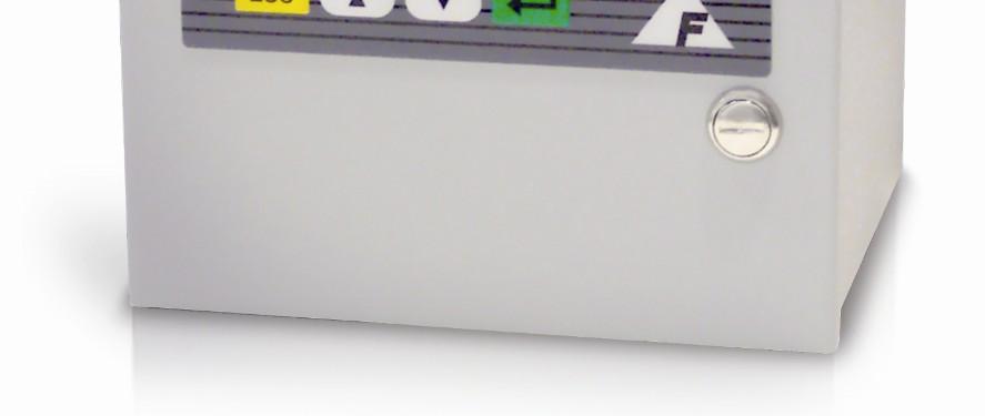
28 REGULATOR SAMPLE INLET 1/8"COMPRESSION J1 A1-COM A1-NO A1-NC A2-COM A2-NO A2-NC GND J3 +24V 24V RTN GND J5 LOOP + LOOP - J7 TEMP + TEMP - SNSR + SNSR - SE+ (H+) SE - GND (H-) J2 A3-COM A3-NO A3-NC A4-COM A4-NO A4-NC GND J4 A OUT + A OUT - PUMP - PUMP + FLOW-A FLOW-B J6 EXT-1 + EXT+1 - EXT-2 + EXT-2 - J8 485-RX TX TX 232-RX 485-RX TX GND Figure 9: Regulator Installation 5.8 Stainless Steel Outlet Tubing Analyzers can be equipped with a 1/8-inch compression stainless steel outlet tube. When this option is provided, the analyzer cannot be equipped with the quick-disconnect fitting at the flowmeter outlet. Because of the rigid outlet tube, the Sensor Assembly can only be removed after both inlet and outlet bulkhead retainer nuts are removed. A 7/16-inch wrench is needed for the inlet nut; and a ½-inch wrench is used on the outlet nut. When reinstalling the sensor, make sure both bulkhead fitting hex sections are oriented to seat in the retainer blocks on the inside rear of the enclosure. 5.9 Key Lock An optional key lock can be installed in the door of the analyzer to prevent access to the power switch and other internal components. The lock is supplied with two keys. If the analyzer is operating, the key lock does not prevent adjustments from the front panel. Password Protection, described in the User Interface section 24 DF-310E Options
29 under Setup Analyzer Menu, must be used to lockout front panel control changes. REGULATOR FILTER SAMPLE INLET 1/8"COMPRESSION M D O C SED RTN SED SED NUSED NUSED J5 LOOP + LOOP - J7 TEMP + TEMP - SNSR + SNSR - SE+ (H+) SE - GND (H-) A3-NO A3-NC A4-COM A4-NO A4-NC GND J4 A OUT + A OUT - PUMP - PUMP + FLOW-A FLOW-B J6 EXT-1 + EXT+1 - EXT-2 + EXT-2 - J8 485-RX TX TX 232-RX 485-RX TX GND Figure 10: Combined Filter/Regulator Assembly mA Analog Output The optional fully-isolated 4-20 ma output is completely isolated from all other analog outputs and from earth ground. The maximum loop resistance is 1KThe VDC compliance voltage is provided. Connections are made at pins J5-1 (LOOP+) and J5-2 (LOOP-) at the back of the instrument. See page 45 for additional information mA Analog Output If configured at the time of order, the optional 4-20mA output described above can be reduced to 2mA when the Sensor is either turned off manually or turned off automatically due to extended (30 minute) off scale oxygen readings. Use of this function provides information than could be interpreted remotely as an alarm or non-standard condition. See page 66 for additional information on the Sensor Off function. 5.11Relays Up to four optional form C (SPDT) relays (contact closures) are available to Options DF-310E 25
30 assign to alarms or system status flags. One or more alarms or status flags can be assigned to one or more relays. The contacts are rated at 0.3A, 30 VDC under a resistive load. Pin assignments provide relay connecting details. See page 44 for additional information. 5.12Communication Port RS232/485 Either of two communication ports are available at the time of order: RS232C or RS485. This option allows interfacing between the analyzer and other operating systems. A C language software library package is available for customized development of communication software. See page 43 for additional information Expanded Range Scale The optional expanded range scale allows the analog output scaling to be automatically expanded to a larger value when the primary scaling range is exceeded. See page 72 for additional information. 5.14Panel Mount A panel mount option is available. See Figure 11 and Figure 12 below for details. 26 DF-310E Options
31 P P M 4.21 [106.93] 7.59 [192.79] 8.71 [221.23] 4.63 [117.60] 7.75 [196.75] 2.05 [52.07] 2.04 [51.82] 1.17 [29.77] 6.50 [165.13] 7.89 [200.48] Ø.22 [Ø5.59] 4 PL 8.33 [211.48] 9.26 [235.08].30 [7.62] 9.36 [237.87] 9.97 [253.11] Figure 11: Panel Mount Configuration Ø.22 [Ø5.59] 4 PL 4.63 [117.60] 8.44 [214.38] 1.91 [48.39].21 [5.27] 8.95 [227.33] 9.37 [237.87] Figure 12: Cutout Dimensions for Panel Mount Options DF-310E 27
32 5.15Rack Mount P P M 4.21 [106.93] 7.59 [192.79] 7.50 [190.50] 7.75 [196.75] [265.68] 5.25 [133.35] 2.05 [52.07] 2.25 [57.15] 1.17 [29.77] 1.48 [37.59] 6.50 [165.13] 7.89 [200.48] 5.33 [135.32] 8.33 [211.48] [482.60] 9.26 [235.08] Figure 13: Rack Mount 5.16Dual Rack Mount P P M P P M 4.21 [106.93] 7.59 [192.79] 7.50 [190.50] [265.68] 5.25 [133.35] 2.05 [52.07] 2.25 [57.15] 1.17 [29.77] 1.48 [37.59] 6.50 [165.13] 7.89 [200.48] 9.26 [235.08].70 [17.73] 8.33 [211.48].93 [23.52] [482.60] 8.33 [211.48] Figure 14: Dual Rack Mount 5.17 Remote Display The display and keypad may be mounted remotely if noted at the time of order. Following are the dimensions for the hole cutout and mounting screws. The connecting cable must be shielded with the ground attached only to the stud on the rear of the analyzer and wired as shown in Figure DF-310E Options
33 1.21 [30.7] 6.80 [172.7] P P M 4.15 [105.4] ESC.25 [6.4] 6.30 [160.0].25 [6.4] 6-32 UNC-A2 X.50 LG THREADED MOUNTING STUDS 4 PLS.14 [3.5] [92.7] 3.30 [83.8] 1.63 [41.3].40 [10.1].74 [18.7].69 [17.4] PHANTOM LINE REPRESENTS THE PANEL CUT OUT TO ALLOW CLEARANCE FOR DISPLAY ELECTRONICS [138.4] Figure 15: Remote Display Options DF-310E 29
34 Figure 16: Remote Display Wiring 5.18Case Purge NOTE: The case purge option is available on AC powered analyzers only. The DF-310E analyzer can be equipped with an inert gas (nitrogen) purge system. The purge system provides improved protection against an explosion hazard by purging the enclosure to a concentration level below the lower explosive limit. With a 10 scfh flow, the nitrogen purge system provides a minimum of thirty volume changes per hour of the atmosphere inside the analyzer s enclosure. A low-flow switch controls the failsafe feature. AC power is connected to the analyzer through the purge control as long as the low-flow switch contacts are closed. In the event of a partial or full loss of purge gas flow, the low-flow switch opens causing a hermetically sealed relay to disconnect power to the analyzer. The electrical and purge gas connections are at the rear of the analyzer. The 30 DF-310E Options
35 purge system has a maximum supply pressure rating of 100 psig and is connected via a 1/8-inch compression fitting. Dry nitrogen is recommended. AC power is connected by the user at the three-terminal connector block next to the purge gas inlet. See Figure [201.09] SEALED AC POWER CONTROL RELAY J1 J2 A1-COM A3-COM A1-NO A1-NC A3-NO A3-NC A2-COM A4-COM A2-NO A2-NC GND J3 +24V A4-NO A4-NC GND J4 A OUT + A OUT - 24V RTN PUMP - GND PUMP + FLOW-A FLOW-B J5 LOOP + J6 EXT [130.05] LOOP - EXT+1 - EXT-2 + EXT-2 - J7 TEMP + TEMP - J8 485-RX TX TX SNSR + SNSR RX 485-RX - SE+ (H+) 1.63 [41.35] SE TX - GND (H-) 232-GND.60 [15.33] CABINET PURGE FLOW SWITCH 9.70 [246.33] 8.33 [211.48] 9.07 [230.38] P P M CABINET PURGE FLOWMETER AND CONTROL VALVE SAMPLE OUTLET 1/8" COMPRESSION 7.75 [196.75] 4.21 [106.93] SAMPLE INLET 1/8" COMMPRESSION OR 1/4" VCR COMPATIBLE MALE 2.05 [52.07] Figure 17: Case Purge Option Options DF-310E 31
36
37 6 Sample Gas Preparation and Delivery 6.1 The STAB-EL Acid Gas System With the STAB-EL system oxygen measurements in sample gases containing varying amounts of acid gases are possible. As a general guide, the data in Table 5-1 represents the maximum allowable limits of acid gases under continuous operation that can be tolerated with the STAB-EL system. Measuring Range Of Analyzer CO 2 * % SO 2 ppm H 2 S ppm NO X ppm Cl 2 ppm HCL ppm 0-50 ppm ppm ppm ppm ppm 0-10,000 ppm 0-5% 0-10% 0-25% * Concentrations of CO 2 are in percent. One percent is equivalent to 10,000 ppm. Table 2: Maximum Allowable Acid Gas Limits Contact the local Servomex Business Center for recommendations on using the STAB-EL sensor on acid gases other than those listed above. The STAB-EL limits shown in the table represent rough guidelines for continuous exposure. In most cases, substantially higher acid gas levels can be tolerated on a limited duty cycle basis. For example, a ppm sensor can be used to sample a 100% CO 2 background gas for a 15 minute period 3-4 times per week, and the balance of the time sampling from a clean gas like N 2, Ar, H 2, etc. In general, a good guideline is to limit that the loading on the STAB-EL system to not exceed the continuous limits if the total exposure is averaged over a weekly period. Consult with Servomex for details. There are applications where the acid gas components may exceed the upper limits of the STAB-EL system on a continuous basis. In such circumstances a sample dilution system can easily be fabricated to mix clean N 2 with the sample gas in a 2:1 to 20:1 ratio using simple pressure control and flowmeter Sample Gas Preparation and Delivery DF-310E 33
38 components. Depending upon the continuous acid gas level and the oxygen level to be measured, a dilution ratio must be selected such that the resulting O 2 level is accurately measurable and at least one order of magnitude above the O 2 level in the N 2 dilution gas. Contact the local Servomex Business Center for specific recommendations. Another approach when acid gas levels are continuously above the STAB-EL limits is to enhance the inherent capabilities of the sensor by using a scrubber system. The scrubber will remove the bulk of the acid gases, allowing the Analyzer to provide continuous stable measurements. If a breakthrough occurs, the sensor's ability to tolerate high levels of acid gas for limited periods of time will avoid catastrophic loss of performance. Servomex offers a broad range of scrubbers for applications in severe environments. Standard scrubber columns are available in various sizes, and in single or dual bed configurations. The columns are fabricated from clear PVC and are designed to accept a variety of different acid gas absorbent media which have a color-change indication to facilitate convenient changeout. For more information, contact the local Servomex Business Center. 6.2 Sample Gas Scale Factor The optional GSF (Gas Scale Factor) is used to correct for changes in the rate of oxygen diffusion when background gases other than nitrogen are present in the process or sample gas. In many applications, the sample GSF does not need to be altered from the default value of However, if the sample gas has a significantly different diffusivity compared with nitrogen (such as helium or hydrogen), the GSF should be applied. To use the GSF feature, the volumetric percentages of the sample gas are entered as described on page 79 and the total GSF is automatically calculated by the analyzer. Alternately, the GSF factor can be entered manually. The software in the analyzer supports gases as shown in Table 3. Contact the local Servomex Business Center for assistance with gases not listed. For additional information see the section on Gas Scale Factor in the User Interface chapter on page DF-310E Sample Gas Preparation and Delivery
39 Ammonia Argon Butane Carbon Monoxide Ethane Ethylene Helium Hexane Hydrogen Methane Nitrogen Propylene NH 3 Ar C 4 H 10 CO C 2 H 6 C 2 H 4 He C 6 H 14 H 2 CH 4 N 2 C 3 H Disclaimer Table 3: Gas Scale Factors The method used to correct the calibration of the DF-310E Oxygen Analyzer for measurement in non-nitrogen background gases is derived from a wellknown theoretical mass transfer equation. This equation accounts for the change in oxygen diffusion rates through different gases. Although significant empirical work has been done in this field, it is generally accepted that the equation may be only percent accurate. In addition, there is further error introduced when correcting for a "multi" component background gas. This may result in up to an additional 3-5% error. An alternate method when using a non-nitrogen or "multi" component background gas for spanning is to obtain a certified Calibration standard that has been prepared in a background gas that models the average process sample. Care must still be used, however, as certified standards may also have an inaccuracy associated with them. Questions regarding the calculation of a background gas correction factor for a specific application should be directed to the local Servomex Business Center. 6.3 Sample Flow Rate and Pressure The analyzer is factory calibrated at a flow rate of 1.0 scfh, in N 2, and should be operated at that level for optimal accuracy. However, the Servomex Sensor is relatively unaffected by gas sample flow rate, within limits. Sample flow rate should be maintained within the recommended range of 1.0 to 2.0 scfh. The analyzer can be operated at flow rates outside that range, but it should be recalibrated at that different flow rate to maintain optimal accuracy. The analyzer has a small pressure drop (0.2 to 0.5 psi), so relatively small changes in inlet or outlet pressure causes dramatic changes in flow rate. Consequently, it is preferable to vent the outlet to atmosphere so that outlet pressure remains constant, leaving inlet pressure as the only variable to control. Sample Gas Preparation and Delivery DF-310E 35
40 6.3.1 Flow Rate Effects on Sensor Performance Assuming a leak-tight system, higher flow rates may cause O 2 readings to increase by a few percent of reading above the level that would be displayed if flow was within the recommended 1.0 to 2.0 scfh range. Lower flow rates similarly cause O 2 readings to decrease by a few percent of reading. Very low flow rates (below 0.2 scfh) should be avoided as the sample inside of the sensor is no longer representative of the actual sample. The insensitivity to flow rate changes is the basis for the sample system leak detection described below. The sensor output should be virtually constant for readings between 0.5 and 2.0 scfh. Therefore, if O 2 readings become higher at lower flows, then ambient O 2 is leaking into the sample system, or venting from a dead space (closed pocket with trapped higher O 2 level gas) in the sample system. A higher flow rate dilutes the O 2 entering the sample system decreasing the reading. O 2 readings in a leak free sample system should not go up or down significantly with flow changes between 0.5 and 2.0 scfh Checking for Plumbing Leaks using Flow Rate Effects Significant measurement error can be caused by leaks in the plumbing system. A simple test can be performed to identify oxygen intrusion leaks. Observe the analyzer readout at two flow levels: 0.5 and 2.0 scfh. Only a slight increase, if any, in readout will occur in a tight system as the flow is increased. If leakage in the plumbing system exists, then the increased flow results in a substantial decrease in oxygen readout -- typically dropping by 25 to 50 percent. When flow sensitivity is observed, check the plumbing system for leaks. Once proficient with this test, the user can estimate the distance to the leak based on the response time of the reading changes Background Gas Effects on Indicated Flow Rate If the molecular weight of the background gas is much different from N 2, the flowmeter reading is not accurate. The Rotameter type is calibrated for use in air (or N 2 ). Most other gases have molecular weights within ± 25 percent of air. Since the required flow rate is not extremely critical most gases produces reasonably correct readings. The exceptions are light gases such as Helium and Hydrogen whose flow rates should be set to approximately one-third that of Nitrogen or 0.3 scfh Regulator Requirements If the pressure in the sample line varies, but does not drop below 2.0 psig, use a regulator to drop the pressure to approximately 1.0 psig. Set final flow rate with the sensor flow control valve. If a regulator is not used, the flow rate changes when the pressure at the inlet of the flow control valve changes. As long as this pressure variation does not bring the flow rate out of the recommended flow range ( scfh) no regulator is required. A flow change of ±1.0 scfh may result in a small change to the oxygen reading. 36 DF-310E Sample Gas Preparation and Delivery
41 If a pressure change causes the flow rate to move outside the recommended range, an adjustment of the flow control valve must be made. If the adjustment is not made, and the flow rate remains outside the recommended range, the analyzer may not be operating within its stated accuracy Pressure Regulator Purge Regulators used on bottled calibration standards are typically equipped with 2 Bourdon pressure gauges, one to measure the cylinder pressure, and the other to measure the outlet pressure. The regulator must have a metal (preferably stainless steel) diaphragm. It is good practice to install a flow control valve to adjust the flow after the regulator. All user-added upstream plumbing should be consistent with the instrument gas delivery components so that the highest level of integrity can be maintained. All connections should be welded or include metal face-seal components. Pressure gauges are not recommended on regulators used on process sample lines because they add measurement delay time and offer opportunities for leaks Regulator Purge Procedure Before the gas is connected to the analyzer follow the procedure listed below to purge ambient air from the regulator: After securely attaching the regulator to the cylinder, 1. Open the regulator flow control valve slightly. 2. Open the cylinder valve. 3. Set the regulator to its maximum delivery pressure. 4. Adjust the flow control valve to allow a modest flow rate (hissing sound). 5. Close the cylinder valve until the cylinder pressure falls to zero. If equipped with gauges, allow the secondary (output) gauge to approach zero. Otherwise wait for the hissing to nearly stop. 6. Immediately open the cylinder valve to restore full delivery pressure. 7. Repeat steps 5 and 6 five to ten times to thoroughly purge the regulator and gauges. 8. Close the shut off valve on the outlet side of the regulator to isolate the purged regulator from atmospheric contamination. Set the delivery pressure to 5 psig (15 psi for welded sample line with VCR connection. The above procedure insures that any ambient air trapped in the pressure gauges and cavities of the regulator is purged prior to use. Once the regulator is mounted, do not remove it from the cylinder until a fresh cylinder is required Pressure Effects on Sensor Performance If the analyzer is not vented to atmosphere, the sensor pressure is influenced by the conditions downstream of the analyzer. A recalibration under your operating conditions may be desirable to remain within the stated accuracy Sample Gas Preparation and Delivery DF-310E 37
42 specifications. However, in most cases the error introduced is relatively small, and may not affect the process application. NOTE It is not recommended that gauges be installed upstream of the analyzer. The presence of a gauge increases response times and introduces potential leaks to ambient. Sample gas line lengths, fittings and bends should be kept to a minimum to maintain low pressure drops. Larger diameter tubing and fittings reduce pressure drop and also lengthen response time. In general, 1/8-inch tubing should be limited to 15-foot runs; longer runs should be made with 1/4-inch tubing Sample Outlet Backpressure Effects It is always recommended to vent the analyzer to atmospheric pressure. However, if a sample vent or return line is used, attention must be given to maintain a low and consistent backpressure so as not to affect the flow rate. The allowable backpressure on the sensor is ±1 psig. If variations in the vent line pressure are expected, a sub-atmospheric backpressure regulator should be installed on the vent line to maintain an even backpressure on the analyzer. Consider the regulator s pressure drop (typically 1 psi) when designing the sample vent system in order to stay within the ±1 psig pressure limits at the sensor. When not venting the analyzer to atmosphere, it is also suggested to install a fairly high resolution pressure gauge immediately at the analyzer outlet. NOTE If a regulator or gauge is installed on the analyzer outlet, the Stainless Steel Downstream Plumbing option should be installed. 6.4 Sample Gas Compatibility There are a wide range of considerations in determining the gas sample compatibility of the Process Oxygen Analyzer. Servomex attempts to identify all pertinent application details prior to quoting and order processing. All non-typical applications concerning gas sample compatibility must be reviewed by our in-house Application Engineers. It is impossible to accurately predict all of the chemical tolerances under the variety of process gases and process conditions that exist Condensation The analyzer should be installed and operated with a sample gas that is preconditioned (if necessary) to avoid condensation in the gas lines. Several methods are available to minimize the possibility of condensation. If the 38 DF-310E Sample Gas Preparation and Delivery
43 sample gas is a hydrocarbon, maintain the gas temperature 20 F to 40 F above its dew point. In some applications, it may be necessary to chill the sample gas before it enters the analyzer so that the hydrocarbons can be condensed, collected, and removed. It is good practice to pitch the sample gas lines to allow condensables to drain away from the analyzer. Gas sample delivery lines that contain sample gases with high moisture content must not be exposed to temperatures below the dew point Gas Solubility in Aqueous KOH Solution Some sample gas constituents are soluble in the sensor s potassium hydroxide (KOH) electrolyte. Gases that are rated as Soluble to Infinitely-Soluble may pose a threat to the sensor. The sensor should have limited exposure (less than 1% by volume on a continuous basis) to highly water soluble alcohols, such as methanol, and/or be supplemented with periodic electrolyte changes to limit buildup within the electrolyte. Many gas species with infinite solubility in aqueous KOH (such as nitrous oxide (N 2 O), however, do not affect the electrode or sealing materials, or interfere with the O 2 reduction/oxidation reactions. Contact the local Servomex Business Center for recommendations on a specific application Reactivity with KOH Electrolyte Many process sample streams contain various concentrations of acid gases. Acid gases are gases that react with the basic KOH electrolyte solution to form a neutralized solution. The sensor does not operate properly when the electrolyte solution is neutralized. Besides a neutralization of the electrolyte, a base reactive sample gas may have other negative effects, such as a base-catalyzed polymerization reaction. The O 2 electrode reaction sites may become blocked by the polymerized byproduct residue at the interface where the gas sample meets the electrolyte Flammable Sample Gas There is nothing within the analyzer sample system that can ignite a flammable sample gas. However, it is critical to ensure that the sample gas does not escape from the sample system into the analyzer enclosure, or the room, where ignition is possible. Stainless steel plumbing should be used throughout the entire sample system if the sample gas is flammable. Also, the analyzer enclosure can be purged with nitrogen, or the entire Analyzer can be mounted in a purged enclosure, so that any sample gas that escapes the plumbing is diluted Trace acids in the sample gas With the STAB-EL Acid Gas system, oxygen measurements in sample gases containing certain levels of acids are possible. Trace acids are common byproducts of gas distribution system assembly and its accessories. Trace acids can compromise the accuracy of the sensor and its construction if they are not managed properly. See the section Stab-el Acid Gas System on page Sample Gas Preparation and Delivery DF-310E 39
44 33 for more detail. Contact the local Servomex Business Center for recommendations on using the STAB-EL sensor on acid gases other than those listed Sample Gas Temperature Gas temperature should not exceed 50 C (122 F), nor should it fall below 0 C (32 F). Gas temperature can be controlled by passing the gas through 5 to 10 feet of metal tubing that is within the recommended sample temperature. Because of its low thermal mass, the gas sample quickly reaches the gas sample line temperature. Ideally, the analyzer should be operated at a nominal temperature of 70 F. Calibration temperature should be close to operating temperature. If the analyzer is to be operated at an average ambient temperature outside 65 F to 80 F, it should be recalibrated at the operating temperature for optimal performance. NOTE The sensor temperature can be displayed at any time by accessing the Diagnostics Menu, Figure 56. This temperature value is updated at intervals of 15 to 45 seconds Protecting the Analyzer from Process Upsets The analyzer should be protected from extended exposure to high concentrations of oxygen or hostile gases. Automatically solenoid controlled valves should be installed to switch the analyzer over to an N 2 purge when the process reaches some identifiable condition. Gas line maintenance operations must also be examined for their effect on the analyzer. For example, in many pipeline process or normal gas applications the plumbing system is cleaned with either a liquid solvent or detergent solution. Since either causes damage to the sensor, switch the analyzer over to a N 2 bypass purge, or shut off sample flow and power to the analyzer prior to initiating the potentially hazardous process. 6.5 Calibration Gas Considerations Calibrations performed from a bottled, calibrated sample gas, may introduce additional issues that could adversely affect the analyzer calibration Calibration Standards Certified calibration standards are available from gas manufacturers. These standards are available in steel and aluminum cylinders. Steel cylinders are less expensive but do not dependably maintain a stable oxygen concentration for long periods of time. Calibration standards in aluminum cylinders are recommended. Servomex has found that calibration standards in aluminum cylinders are very stable for 40 DF-310E Sample Gas Preparation and Delivery
45 long periods of time (between 6 and 24 months) where steel cylinders should be recalibrated every three months Calibration Cylinder Regulators Regulators used on bottled calibration standards are typically equipped with two Bourdon pressure gauges, one to measure the cylinder pressure, and the other to measure the outlet pressure. The regulator must have a metal (preferably stainless steel) diaphragm. Install a flow control valve after the regulator to adjust the flow Purge Procedure Before the calibration gas is connected to the analyzer follow the procedure listed below to purge ambient air from the regulator which prevents contamination of the gas in the cylinder rendering it useless: After securely attaching the regulator to the cylinder, 1. Open the regulator flow control valve slightly. 2. Open the cylinder valve. 3. Set the regulator to its maximum delivery pressure. 4. Adjust the flow control valve to allow a modest flow rate (hissing sound). 5. Close the cylinder valve until the cylinder pressure falls to zero. If equipped with gauges, allow the secondary (output) gauge to approach zero. Otherwise wait for the hissing to nearly stop. 6. Immediately open the cylinder valve to restore full delivery pressure. 7. Repeat steps 5 and 6 five to ten times to thoroughly purge the regulator and gauges. 8. Close the shut off valve on the outlet side of the regulator to isolate the purged regulator from atmospheric contamination. 9. Set the delivery pressure to 5 psig (15 psi for welded sample line with VCR connection. Once the regulator is mounted and purged, do not remove it from the cylinder until a fresh cylinder is required Sample Gas Delivery and Vent Pressure during Calibration The most accurate calibration is obtained when the analyzer is plumbed into the gas sample system so that the analyzer is under actual process operating conditions. But when the process sample is being delivered to the analyzer under Vacuum conditions, or being returned from the sample outlet under either positive pressure or Vacuum conditions the operating pressure at the sensor is likely to be quite different than under factory calibration conditions. For systems where the gas sample is not vented to atmosphere, the analyzer outlet should remain connected in the same manner during calibration, if possible. This ensures that downstream pressure effects on the sensor are the Sample Gas Preparation and Delivery DF-310E 41
46 same during calibration and process monitoring. Use the flow control valve on the regulator to meter the calibration gas to the analyzer at the suggested 1.0 scfh flow. By leaving the analyzer s flow controls untouched from when the analyzer is used on process, the calibration pressure duplicates the process sampling pressure Background Gas Effects on Calibration Flow rate Ideally, the calibration gas and the sample gas have the same gas composition, and as a result, the indicated flow rate during calibration and process sampling are identical. However, if the composition of the calibration and sample gases are not the same, the flow rate indicated on the rotameter may need to be adjusted. Light gases, such as H 2 and He, have a higher flow rate than is indicated on the flowmeter. As a result, the flow rate of the light gas should be set to one third of the flow specifications found in this manual. For example: The recommended flow rate for N 2 is 1.0 scfh. In H 2 or He service, the recommended flow rate (as indicated on the analyzer flowmeter) is 0.3 scfh Gas Scale Factor (GSF) If possible, the background of the calibration gas should be the same as the process sample gas. If not, a gas scale factor may have to be applied to the calibration gas oxygen readings because of the difference between the diffusion rate of oxygen in nitrogen (factory calibration gas) versus the diffusion rate in the user s calibration gas. The Sample Gas Preparation and Delivery section discusses the proper setting of the gas scale factor option during calibration as well as during process gas measurement. 42 DF-310E Sample Gas Preparation and Delivery
47 7 Connecting to External Devices The analyzer can be interfaced to a variety of external devices via the ports on the rear panel. Alarm contacts, voltage, and current outputs, and serial communications are supported. NOTE When using external devices to monitor the O2 reading, the analyzer should never be left in a menu screen unattended, but always in the O2 readout mode. 7.1 The Comm Port The optional Comm Port is used for communication via RS-232C or RS-485 protocol. Up to 32 units may be accessed via RS-485. Operating parameters are 8 bits, no parity, and one stop bit. Baud rate may be selected from the menu on the display. A library of interface functions, written in C, is available to allow programmers to create custom interface program for accessing the communication port. The Interface C Library Reference Manual comes with a disk containing Microsoft and Borland versions of the object code. The Comm port (J8) terminals are defined as follows: J RX + Data received by the analyzer from the device (RS-485) J TX + Data transmitted by the analyzer to the device (RS-485) J TX Data transmitted by the analyzer to the device (RS-232) J RX Data received by the analyzer from the device (RS-232) J RX - Data received by the analyzer from the device (RS-485) J8-6 J TX - Data transmitted by the analyzer to the device (RS-485) J GND Ground Table 4: Comm Port (J8) Connector Pinout J7 TEMP + TEMP - SNSR + SNSR - SE+ (H+) SE - GND (H-) J8 485-RX TX TX 232-RX 485-RX TX GND Figure 18: J7/J8 Connector Wiring Connecting to External Devices DF-310E 43
48 NOTE To avoid ground-loop conflicts when using RS-232C or RS-485 for communications, make connections to external recorders or data acquisition systems through a differential input, or a single-ended input that is not referenced to Earth Ground. When connecting the Process Oxygen Analyzer to a computer via an RS-232 or RS-485 communication cable, a Ferrite Sleeve is required around the cable in a single-turn configuration. It is recommended that the proper Servomex cable be used for this purpose. 7.2 Relay Ports Connections to four optional form C (SPDT) relays (contact closures) are provided on the rear of the analyzer at connector J1 and J2. These can be used in conjunction with up to seven alarms. The contacts are rated at 0.3A, 30 VDC under a resistive load. They are not designed to switch AC power. The relay contacts can be programmed for up to four Oxygen Alarms, plus Temperature, Low Flow, Electrolyte Condition and the Replenishment Solution Reminder alarm. A relay can be assigned to any alarm through the display menu. The Normally Open (No alarm) contact connects to common when an alarm occurs or when power to the instrument is lost. Figure 19: J1/J2 Connector Wiring J1-1 A1-COM Alarm 1 Common J1-2 A1-NO Alarm 1 Normally Open J1-3 A1-NC Alarm 1 Normally Closed J1-4 A2-COM Alarm 2 Common J1-5 J1-6 A2-NO Alarm 2 Normally Open J1-7 A2-NC Alarm 2 Normally Closed J1-8 GND Ground 44 DF-310E Connecting to External Devices
49 J2-1 A3-COM Alarm 3 Common J2-2 A3-NO Alarm 3 Normally Open J2-3 A3-NC Alarm 3 Normally Closed J2-4 J2-5 A4-COM Alarm 4 Common J2-6 A4-NO Alarm 4 Normally Open J2-7 A4-NC Alarm 4 Normally Closed J2-8 GND Ground Table 5: Relay Port Connectors (J1, J2) Pin Out 7.3 Analog Outputs In addition to the wiring of the analog outputs as described below, see page 70 for additional information on scaling the outputs through the firmware Analog Voltage Output Connector J4 provides connections to the non-isolated analog voltage output signal (0 to 5, or 0 to 10 VDC, selectable). For details regarding how to switch the full-scale output see section below. J3 +24V 24V RTN GND J4 A OUT + A OUT - PUMP - PUMP + FLOW-A FLOW-B J3/J4 Connector Wiring J4-1 AOUT+ Analog Voltage Output + J4-2 AOUT- Analog Voltage Output - Table 6: Analog Voltage Output Connector (J4) Pin Out Procedure to change the Full Scale Analog Output Voltage The following procedure should be used to change the full scale analog output voltage. The options are 5.0 and 10.0 VDC. 1. Shut-off and disconnect all power from the analyzer. 2. Label and remove all connections from the rear of the analyzer. 3. Open the door and disconnect the sensor and display cables. See page Remove the two screws from the rear of the unit. See page 18. Connecting to External Devices DF-310E 45
50 5. Remove the circuit board assembly from the cabinet. 6. Remove the four screws that hold the sheet metal cover in place. Remove the cover and set aside. 7. Locate jumper # JP14 in the center, directly below the relays in the upper third of the board. 8. Using the information in Table 7, place a jumper (short) between the appropriate pins to obtain the desired full scale output. 9. Reassemble and install the circuit boards back into the analyzer. 10. Reconnect all cables and power up the analyzer. 11. From the Diagnostics Menu, select Test Output, and set the output to 100% full scale. 12. With a DVM, confirm that the analog output voltage is proper. If it needs to be adjusted slightly, use the potentiometer located third from the top on the front of the circuit board, above the Servomex symbol. Full Scale Output Voltage Jumper Number 5.0 VDC None 10.0 VDC 14 Table 7: Analog Output Voltage Jumpers mA Output The optional fully-isolated 4-20mA output is completely isolated from all other analog outputs and from earth ground. The maximum loop resistance is 1KThe VDC compliance voltage is provided. Connections are made at pins J5-1 (LOOP+) and J5-2 (LOOP-) at the back of the instrument. J5 LOOP + LOOP - J6 EXT-1 + EXT+1 - EXT-2 + EXT-2 - Figure 20: J5/J6 Connector Wiring J5-1 LOOP ma Output + J5-2 LOOP ma Output - Table 8: 4-20 ma Analog Current Loop Connector (J5) Pin Out Sensor Off 4-20mA Signal If configured at the time of order, the optional 4-20mA output described above can be reduced to 2mA when the Sensor is either turned off manually or turned off automatically due to extended (30 minute) off scale oxygen readings. Use of this function provides information than could be interpreted remotely as an alarm or non-standard condition. See page 66 for additional information on the Sensor Off function. 46 DF-310E Connecting to External Devices
51 7.3.3 Alignment Procedure for Analog Voltage and Current Loop Outputs All output connections should be made before the alignment is started. It is assumed for the purpose of this alignment that the full-scale analog voltage output is 10 VDC. Use the Test Outputs screen as described on page 89 to set the output to the desired level after which the alignment adjustments are made as follows: 1. Set the output to 0% 2. Adjust the analog voltage output (1) to V +/- 1mV, adjust the current loop output (2) to 4.00mA +/-.01mA 3. Set the output to 100% 4. Adjust the analog voltage output (3) to V +/- 1 mv, and adjust the current loop output (4) to 20.00mA +/-.01mA VDC: SPAN ADJUSTMENT (3) 0-10 VDC: 0 VDC ADJUSTMENT (1) 4-20 ma: 4 ma ADJUSTMENT (2) 4-20 ma: 20 ma ADJUSTMENT (4) 7.4 Remote Controls Figure 21: Analog Voltage Output and 4-20mA Adjustments Remote Sensor Control J6 Connector If equipped, the oxygen sensor can be turned on and off remotely through the pins labeled EXT 1 or EXT 2 on the J6 connector. If equipped, the EXT Functions screen, see page 91, will indicate to what set of EXT contacts this option is assigned, either 1 or 2. Connecting to External Devices DF-310E 47
52 J5 LOOP + LOOP - J6 EXT-1 + EXT-1 - EXT-2 + EXT-2 - Figure 22: J5/J6 Connector Wiring J6-1 EXT-1 + External Control Input (+) J6-2 EXT-1 - External Control Input (-) J6-3 EXT-2 + External Control Input (+) J6-4 EXT-2 - External Control Input (-) Table 9: Remote Control Connector (J6) While the display is in the normal O2 mode, a voltage of 5-28VDC applied to the appropriate contact pairs labeled EXT 1 (+/-) or EXT 2 (+/-) will turn the sensor off. The oxygen sensor will stay off until this potential is removed. NOTE: Turning the sensor off in this way will make control of the sensor from the keypad impossible. In addition, the Automatic Sensor off function is disabled. NOTE: Controlling the sensor voltage in this way will disable the Automatic Sensor off function. NOTE: The audible alarm normally associated with the sensor off function is disabled with this option. See the wiring diagram in Figure Remote Pump Control J6 Connector The pump enables the analyzer to operate on gas sample streams between 2.0 psig vacuum and 2.0 psig positive pressure. If the analyzer is equipped with a pump, it will also have a downstream Flow Control Valve mounted in the bottom of the flow meter. When using the pump, always use this downstream valve to control the gas flow rate and leave all up stream valves wide open. If the pump is not in use, (positive pressure application) always control the gas flow with an upstream valve or regulator and leave all down stream valves wide open. CAUTION Do not use an upstream valve to control flow if the analyzer is operating on a pump. The on-board pump, if equipped, is controlled from the Controls Menu. See the User Manual for additional information. Connections to power a remote pump are made through the PUMP and PUMP + pins on connector J4. The wires should be in a shielded cable (separate from the sensor signal) with the shield attached to the frame ground. The pump cable should be of sufficient size for the required run (see Table 10 below) and should not share the same conduit as the sensor cable. See the wiring diagram in Figure DF-310E Connecting to External Devices
53 Pump Cable (Must be separate from sensor cable) Distance in Feet Minimum Wire Size #20 AWG #18 AWG Table 10: Pump Cable Specification J3 +24V 24V RTN GND J4 A OUT + A OUT - PUMP - PUMP + FLOW-A FLOW-B Figure 23: J3/J4 Connector Wiring In addition, the following options are available: If factory configured, Servomex will supply the standard pump that the user may install remotely and power through the PUMP and PUMP + connections on the rear panel connector J4. Control would be accomplished in the same manner as a standard pump. OR If factory configured, a switch closure rated at 1A/30VDC can be supplied between the PUMP -, + connections on the rear panel connector J4. The contacts can be used to control a Servomex supplied pump that is powered from a separate 12 VDC,.3 A source. Control of the pump would be accomplished in the same manner as a standard pump. OR If equipped, the pump may also be turned on and off remotely through the pins labeled EXT 1 or EXT 2 on the J6 connector. If equipped, the Diagnostics Screen will indicate to what set of EXT contacts this option is assigned, either 1 or 2. While the display is in the normal O2 mode, a voltage of 5-28 VDC applied to the appropriate contact pairs labeled EXT 1 or EXT 2 will turn the pump off. The pump will stay off until this potential is removed. NOTE: Turning the pump off in this way will make control of the pump from the keypad impossible. 7.5 Remote Sensor Installations NOTE Remote sensor installations void CSA approval, if any. The oxygen sensor for a DF Series analyzer may be installed outside of the analyzer cabinet. Areas of high convected or radiated heat must always be avoided. If installed outdoors, the sensor enclosure must be shielded from the sun to avoid overheating. In addition, a heater must be installed in the enclosure in areas where the temperature goes below freezing. (See page 53) Care must be taken to use high quality cable and techniques when making remote electrical Connecting to External Devices DF-310E 49
54 connections. See the wiring diagram in Figure 30 and refer to Table 10 and Table 11 for wire sizes and lengths. Following are three remote sensor configurations and wiring diagrams. Care must be taken when making up gas fittings on the sensor when mounted on a remote bracket as shown in Figure 24 below. A backing wrench must always be used (in particular for VCR connections) when connecting the gas sample line to the sensor. The inlet fitting, although epoxied, is very delicate and the seal can easily be damaged if it is allowed to spin as the connection is tightened. A inch orifice is included with 0-50ppm sensors and must be installed at the sensor inlet in order to control gas flow. Contact Servomex for additional information on remote sensor installations Sensor on Remote Bracket with Optional Pump CAUTION Always use a backing wrench when connecting the gas sample line to a remote sensor [103.89] 7.73 [196.29] Ø.28 [Ø7.11] 4 PL 1.50 [38.10] 1.57 [39.88] 7.02 [178.28] 4.88 [123.83] SECONDARY ELECTRODE - (WHT/BLU) SECONDARY ELECTRODE + (WHT/RED) SENSOR - (WHT/YEL) SENSOR + (WHT/BLK/RED) TEMP - PUMP - TEMP + GROUND PUMP + FLOW SWITCH FLOW SWITCH Figure 24: Remote Sensor with Optional Pump 50 DF-310E Connecting to External Devices
55 7.5.2 Sensor in NEMA 4 Enclosure Ø.44 [Ø11.18] THRU 4 PL 7.00 [177.80] PUMP [285.62] [254.00] FLOW SWITCH ROTOMETER FLOW CONTROL VALVE OXYGEN SENSOR SAMPLE INLET SAMPLE OUTLET 7.42 [188.58] SIGNAL OUTPUT 4.71 [119.75] 2.96 [75.30] 2.96 [75.25] 1.23 [31.36] 1.93 [49.02] 2.75 [69.85] AC POWER 7.00 [177.80] 9.00 [228.60] Figure 25: Remote Sensor Mounted in NEMA 4 Enclosure Connecting to External Devices DF-310E 51
56 7.5.3 Sensor in NEMA 7 Enclosure Figure 26: Remote Sensor Mounted in NEMA 7 Enclosure 52 DF-310E Connecting to External Devices
57 5.25 [133.35] 3.00 [76.20] SAMPLE INLET 1/4" COMPRESSION ELECTROLYTE MAINTENANCE ACCESS FLOWMETER WITH INTEGRAL CONTROL VALVE (OPTIONAL) SAMPLE OUTLET 1/4" COMPRESSION Ø.44 [Ø11.11] THRU 4 PL.75 NPT ELECTRICAL CONNECTION TO CONTROL ENCLOSURE 8.50 [215.90] 9.75 [247.65] [279.40] 7.25 [184.15] 2.50 [63.50] 2.50 [63.50] 9.00 [228.60] [260.35] 8.38 [212.73] 3.00 [76.20] Figure 27: NEMA 7 Enclosure Mounting Dimensions Temperature Control in R4/R7 Enclosures R4 and R7 enclosures may be supplied with the temperature control option. Typically this option is installed in an effort to minimize diurnal changes in outdoor installations, or when the sensor must be kept at an elevated temperature in order to minimize condensation. NOTE: The customer must supply the electrical power (110/220 VAC, 150 Watts) for this option. For most applications, the sensor and electronics are maintained at a temperature of degrees F. The temperature controller, located in the R4 or R7 enclosure, is set at the factory and typically requires no adjustment unless components are changed or application conditions require higher temperatures. In the event that the enclosure temperature must be adjusted, follow the steps below. 1) Obtain a temperature measurement device capable of measuring the desired operating temperature to an accuracy of +/- 2 degrees F. Connecting to External Devices DF-310E 53
58 2) Open the R4 door or remove the R7 cover. Attach the temperature measuring probe to the side of the oxygen sensor. Be sure to cover the enclosure opening to prevent cooling. 3) Turn on the analyzer and enclosure heater. Allow at least four hours for the enclosure temperature to stabilize. 4) Locate the temperature control potentiometer on the circuit board in the enclosure above the terminal strip. See Figure 28. Turn it clockwise to increase the temperature and counterclockwise to decrease it. After each adjustment re-cover the enclosure and allow at least an hour for it to stabilize at the new temperature. Figure 28: Temperature Control in R7 Enclosure Remote Sensor Connections Connector J7 There are three pair of connections that must be made between the oxygen sensor and connector J7 on the electronics chassis. They are labeled SNSR + and -, SE + and and TEMP + and -. It is critical for optimum operation, and to prevent damage to the sensor, that the proper polarity be maintained on all electrical connections. These connections should be made through a shielded, twisted pair cable sized according to Table 11. The shield should be terminated only at the Ground connection labeled GND on the same connector. To avoid ground loops, the shield should be left open and not attached to the remote sensor chassis. See Figure 30 for wiring connections. Oxygen Sensor Cable Sizes Distance in Feet Minimum Wire Size #20 AWG #18 AWG #16 AWG #14 AWG Table 11: Remote Sensor Cable Sizes 54 DF-310E Connecting to External Devices
59 J7 TEMP + TEMP - SNSR + SNSR - SE+ (H+) SE - GND (H-) J8 485-RX TX TX 232-RX 485-RX TX GND Figure 29: Remote Sensor Connector J7 Figure 30: Remote Sensor/Pump Wiring Diagram Connecting to External Devices DF-310E 55
60 7.5.6 Z-Purge Protection on R4 Enclosure Before applying power to the to the analyzer, the Z-Purge unit must be installed and operating properly. For loss of purge protection, wire the Z-Purge alarm contacts to a customer provided alarm. Normally open and normally closed contacts are provided. Alternatively the contacts can be used to interrupt the input power to the analyzer. The switch requires either AC or DC input power, as indicated on the faceplate. For installation and wiring instructions, see the manufacturers information included with the switch. NOTE: All electrical connections to the switch must be made according to applicable local and safety standards. A supply of air or N2 regulated between psig is required [419.10] 7.60 [193.15] PURGE PROTECTION STYSTEM (OPTIONAL) REQUIRES psig INSTRUMENT AIR OR N 9.00 [228.60] 7.00 [177.80] 5.00 [127.00] 2.00 [50.80] [317.50] [285.62] [321.61] 1.41 [35.86] 1.25 [31.75] 1.00 [25.40] 7.00 [177.80] 1.41 [35.93] 1.93 [49.02] 3.14 [79.82] SAMPLE INLET 1/4" COMPRESSION (STD) 1/4" VCR COMPATIBLE (OPTIONAL) 2.75 [69.85] 7.00 [177.80] SAMPLE OUTLET 1/4" COMPRESSION Figure 31: Z-Purge Protection on R4 Sensor Enclosure 56 DF-310E Connecting to External Devices
61 Procedure for setting pressure and flow through the enclosure: 1. Verify proper operation of the Z-Purge unit as described in this section, while the environment is in a safe condition. 2. Remove the four cover screws on the Z-Purge pressure switch. 3. Check that the pressure calibration screw on the pressure switch is backed out as far as possible to the minimum pressure setting of 0.15 inches of water. Check the enclosure pressure with a suitable instrument if possible. 4. Close the Z-Purge pressure regulator (fully counter clock-wise) 5. Fully open the Z-Purge flowmeter needle valve. (fully clock-wise) 6. Open the instrument air/n2 supply to the Z-Purge regulator. (pre-regulated to the minimum pressure required to supply 50 scfh of flow to the enclosure). 7. Open the Z-Purge regulator sufficiently to allow 50 scfh to the enclosure. 8. Verify that the alarm pressure switch has been deactivated (is not in an alarm condition). 9. Purge the enclosure for 15 minutes at 50 scfh. 10. Reduce the purge flow rate to a minimum of 5 to 10 scfh using the flowmeter needle valve, making certain that the alarm pressure switch remains deactivated (not in an alarm condition). If the purge switch activates, confirm that the enclosure is tight and increase the flow rate as necessary. 11. The analyzer may now be turned on. Connecting to External Devices DF-310E 57
62
63 8 User Interface 8.1 The Data Display Screen When the DF-310E Process Oxygen Analyzer is powered up, it goes through a series of internal diagnostic tests which take about five seconds. After the tests, the Servomex logo appears for ten seconds. The display will then show the Data Display Screen as shown in Figure P P M OUT : *Menu GSF: Figure 32: Data Display and Keypad The numerical information shown is representative. Different values will probably be observed on the display. There are four pressure sensitive keys below the display. The keys are used as follows: ESC - Returns the display to the previous screen, or may be used to move to the left when within a data field selection. - Scrolls up in a menu or data selection. - Scrolls down in a menu or data selection. - Accepts the selected (asterisk) entry, allows data field selection, and may be used to move to the right when within a data field selection. The Annunciator Line provides information about the status of the Analyzer, and alarm conditions. The Annunciator Line is displayed on the Main Menu Screen. The Data Line indicates the measured oxygen concentration (e.g ppm). In this manual all concentrations will be shown in ppm O 2. For instruments that display data in percent (%) O 2 all actions are identical, but engineering units will be reported in percent (%). User Interface DF-310E 59
64 Below the Data Line is a display of the Analog Output Range settings. The analog outputs are scaled over the range displayed in this area. Factory standard analog outputs are 0-10 VDC and Isolated 4-20 ma. Setting the analog voltage output is described on page 70. If the Analyzer is equipped with the Expanded Range Scale option the Analog Output Range value will change from OUT: x-xxxx to XPOUT: x-xxxx, and will appear in reverse video, when the expanded range scale is active. * Menu indicates that if is pressed, the Main Menu display, Figure 33, will appear. GSF indicates the present Gas Scale Factor. The Gas Scale Factor is described on page 74. If the Analyzer is not equipped with the GSF option, or if N 2 is selected from the GSF table, then no GSF is displayed. The legend "OVER RANGE" will overwrite the Oxygen display if the instrument analog to digital converter reads a value which is over its full scale range. During an over range condition the oxygen information is not valid. The analog output will be at maximum (pegged). An OVER RANGE condition will result in a continuous alarm tone, which may be silenced by pressing ESC. The legend SENSOR OFF! will overwrite the Oxygen display if the sensor polarization voltage is turned off by using the Sensor selection in the Controls menu. The polarization voltage will automatically turn off if the Analyzer is OVER RANGE for more than 30 minutes. When the sensor is off the analog output falls to zero volts and the 4-20 ma output falls to 4 ma. An optional relay may be configured to indicate that the sensor is off. A SENSOR OFF! condition will result in an intermittent alarm tone, which may be silenced by pressing ESC. NOTE: The automatic sensor off function is disabled if the display is not in the main O2 readout mode. A reverse video overlay will appear over the center of the display for the following alarms: Oxygen (1,2,3,4), Temperature (T), Flow (F), and Electrolyte Condition (E). The overlay appears and disappears at intervals so that the Oxygen reading is still visible. If there are several alarms in progress all of the alarm overlays will be displayed in sequence. The overlay also indicates the set point value and whether the alarm condition is a high or low alarm. If the alarm is a Flow or Electrolyte Condition alarm the set point is not displayed because these alarms do not have set point values. Audible annunciation can be activated for each of the alarms. If annunciation is activated, a continuous tone will occur when the overlay is displayed. Pressing ESC while the overlay is displayed will silence the tone and cause the overlay to disappear. Once an alarm has been acknowledged (by pressing ESC) its number will be continuously displayed in the Data Display Window on the Annunciator Line. The numbers are assigned as follows: The alarm number will clear only after the alarm condition is over. In the case of simultaneous alarms, each will alternately overwrite the display. Successive presses of ESC (as the overwrite is displayed) are necessary to clear the overwrite and 60 DF-310E User Interface
65 annunciation. This will not clear the alarm. Only a restoration of the condition that existed prior to the alarm will clear the alarm. Alarm Number Function 1 Oxygen 1 2 Oxygen 2 3 Oxygen 3 4 Oxygen 4 T Temperature F Flow E Electrolyte Condition Table 12: Alarm Identification There are also a number of special messages that can appear on the Annunciator Line of the display: CHECK FLUID Indicates that a user set time period has expired after which the electrolyte level should be checked and Replenishment Solution should be added if necessary. TEMP OVER RANGE - Indicates that the sensor temperature is over 50C or that the temperature probe is disconnected. This alarm results in a continuous tone that may be silenced by pressing ESC. UNDER RANGE - Indicates that the oxygen level is below the calibrated zero. UNCALIBRATED - Warns that the Analyzer is not calibrated, or that NOVRAM data has been corrupted. If there is an acknowledged alarm indicated in the Annunciator Line, special messages will appear in the upper left corner of the oxygen display box. Temp Over Range will show TO, and Under Range will show UR. EXT SENSOR! Indicates that the oxygen sensor polarization voltage has been turned off remotely. EXT PUMP Indicates that the pump has been turned on remotely. Other possible messages, that may appear on various screens, include Wait!, and Memory Error!. Wait! indicates that the instrument is performing an operation that is time consuming (> 10 seconds), such as an internal electrical zero calibration. Memory Error! indicates that the instrument has failed the boot-up memory test. The letters CHG, BAT and LOW may appear vertically on the right side of the display on units equipped with the NiMH battery backup option. User Interface DF-310E 61
66 3.43 ppm 62 DF-310E User Interface
67 8.2 Main Menu The Main Menu, Figure 33, is accessed by pressing from the Data Display Window. Alarm Overlay information will continue to display over the Main Menu. Figure 33: Main Menu The first three lines of the Main Menu display the firmware version, followed by the instrument serial number and the range of the Analyzer. Four screens can be accessed from the main screen: Controls - Used to turn on the pump, the sensor voltage, choose sensor off relay, and select power up default conditions for the above functions. See page 65. Set-Up Menu - Used to set alarm parameters, the recorder output level and functions, configure communication port, to enter the gas scale factor, to perform or check the span calibration, or to install a replacement sensor. See page Password - Used to set passwords and indicate which menus are "password" protected Maintenance Used to access three screens related to replenishment solution addition, oxygen calibration and diagnostics. The diagram on the previous shows the "Menu Tree" for the operator interface. Sufficient detail is provided to orient the user during instrument set-up; however, not all the program details are illustrated in this diagram. Each level in the Main Menu allows the user to access options for setting and testing instrument parameters. Ellipsis (...) after an entry indicates that additional screens follow. User Interface DF-310E 63
68 8.2.1 Keypad Operation The following protocols are used to operate the Analyzer through the front keypad: To access a level, use the or key to move the asterisk (*) to the desired level and press. To edit a numerical value, use the key to highlight (reverse video) the digit to be changed. Successive use of the key will highlight the digits on a left to right basis. Use of the ESC key will move the highlighting back to the left and eventually cancel any adjustment. The rightmost digit will be the active digit for editing. Use or to adjust the desired value. After the desired numerical value has been entered, press the key until the number no longer appears in reverse video. The ESC key is used to return to the previous screen without changing any parameters that may have been altered. If any parameters have been edited without updating memory, the display will present the message "ABANDON CHANGES?, FOR YES". All parameter changes will be lost if the key is pressed. Select the UPDATE & QUIT choice using the previous menu. to save the changes and automatically return to 64 DF-310E User Interface
69 8.3 Controls Menu The Controls menu is used to turn on or off a number of optional features of the Oxygen Analyzer. When the Controls menu is selected, and the appropriate password is entered (if required), the display will show Figure 34. Figure 34: Controls Menu Pump (Optional) - After accessing the Pump entry, the pump is toggled ON or OFF by pressing. If the Analyzer does not have a pump, NA will be displayed. See the section on ESC, page 67, for additional information about leaving the menu after changing the Pump setting. See the section on Remote Controls, page 47, for additional information on remote control of the pump. NOTE Analyzers with pumps are fitted with a valve on the rotameter (downstream of the sensor) and a valve on the sensor inlet (upstream of the sensor). When using a pump to draw a gas sample at less than 0.2 psig, the downstream rotameter valve is used as the flow control valve. The sensor inlet (upstream) valve is shipped from the factory in the fully opened (counter-clockwise) position. Its position should not be changed unless the Analyzer is operated on positive pressure, e.g., when measuring a sample greater than 0.2 psig (but less than the maximum limit of 10 psig) that is vented to atmosphere. Likewise, when operating with a positive pressure the rotameter (downstream) valve should be fully opened and the upstream flow control valve used for flow control. FAILURE TO FOLLOW THESE INSTRUCTIONS MAY CAUSE THE SENSOR TO EXPERIENCE OVER OR UNDER PRESSURE WHICH MAY CAUSE PERMANENT DAMAGE. User Interface DF-310E 65
70 8.3.2 Sensor Polarization After accessing the Sensor entry, the sensor power is toggled ON or OFF by pressing. The sensor ON command applies a polarizing voltage to the sensor. See the section on ESC, page 67, for additional information about leaving the menu after changing the Sensor setting. The Analyzer has been programmed to protect the sensor from extended operation in an overrange condition (> 30 minutes). If such a condition exists, the software will turn off the polarizing voltage to the sensor. A message will be displayed indicating that the sensor has been turned off, and an intermittent beep will occur as in Figure 35. The beep can be silenced and message canceled by pressing ESC. When ESC is pressed a reverse video SENSOR OFF! legend will overlay the oxygen display. The user should investigate the reason for the excessively high O 2 level, remedy the situation, and then restore power to the sensor via the Controls menu. The oxygen value is approximately zero when the sensor is off. Also, the analog outputs will go to zero, so any low Oxygen alarms set above zero will trigger on. NOTE: The automatic sensor off function is disabled if the display is not in the main O2 readout mode. See the section on Remote Controls, page 47, for additional information on remote control of the sensor polarization voltage. Figure 35: Sensor Shut-off Warning SensOFF Relay When the sensor is manually turned off from the front panel, or automatically turned off because the instrument has been over-range for more than 30 minutes, a relay may be assigned to signal that the sensor is off. This feature is important when the Analyzer is used in an unattended area, so that a remote operator can be notified that the instrument is no longer measuring oxygen. If the instrument is not equipped with any relays this selection will show NA. It is possible to assign more than one alarm or status condition to any relay. Since the status condition of the sensor, being switched off, signifies an Analyzer Off-line condition, it is important to make sure that the relay assigned to SensOFF service is only assigned to alarm conditions signifying similar levels of alert, such as a Low Flow Alarm. Note: Alarm or Analyzer status conditions that signal an Analyzer off-line fault condition (such as sensor off) can be assigned to a single relay contact used as a trouble indicator. If the Analyzer signal is only monitored remotely, it is suggested to route the 4-20 madc signal through the Analyzer Trouble relay such that an alarm condition will cause the relay to break the current loop. This method allows a computerized system to be configured to detect an analyzer fault condition whenever the 4-20 madc signal is below 4 ma. 66 DF-310E User Interface
71 Sensor Off 4-20mA Signal If configured at the time of order, the 4-20mA output can be reduced to 2mA when the Sensor is either manually or automatically turned off. See page 25 for additional information on the 2-20mA option P(o)w(e)r UP When the Analyzer is powered down, and then turned back on, the pump controls default to OFF, and the Sensor defaults to ON. This activity is the DEFAULT operational mode of the pump and sensor. Instead, it is possible to store the states of the pump and sensor every time they change and allow the LAST state to be reestablished when the Analyzer is powered up. The selection PwrUP toggles between DEFAULT and LAST ESC If only the Pump, or Sensor selection has been changed, and the PwrUP selection is set to DEFAULT, the Controls menu may be exited with ESC. The new changes will be in effect. If SensOFF Relay or PwrUP has been changed, and the changes are to be stored, or the PwrUP selection is set to LAST, the menu should be exited by selecting Update and Quit. If the changes are to be discarded press ESC. The Analyzer will present the message ABANDON CHANGES?, FOR YES. Press enter and the display will return to the Data Display Screen. 8.4 Set-Up Menu Note: When the Set-up entry is selected from the Main Menu, a DISABLING ALARMS message appears which notifies the user that the alarms have been temporarily disabled. The alarm overlay messages will not show in the display. Relays will remain in the alarm state that immediately preceded the Disabling Alarms message. The Set-Up Menu is used to establish a variety of Analyzer parameters. When the selection is made from the Main Menu, Figure 33, and the appropriate password is entered (if required), Figure 36 is shown. Figure 36: Setup Menu Each entry in Figure 36 leads to a sub-menu. To select the desired sub-menu, use the and keys to place the asterisk next to it, then press. A new display will be shown as indicated below. User Interface DF-310E 67
72 8.4.1 Alarms The Alarms screen is used to set or determine the status of alarms. When the Alarms entry is selected from Figure 36, the display will present Figure 37. Figure 37: Alarm Setup Menu To select an alarm to edit, use the and keys to move the asterisk. Press when the alarm is indicated. If (NA) is displayed next to any entry, that alarm option is Not Available O 2 Alarms If an O 2 alarm has been selected from the Alarm Setup Screen Figure 37, the display will show Figure 38. Figure 38: Oxygen Alarm Menu Figure 39: Oxygen Alarm Setup Screen (Alarm not used) After selecting an Alarm with the and keys, use to toggle the alarm On (USED) or Off (NU). When an unused alarm (NU) is accessed, the display will appear as shown in Figure 39. (Oxygen ALARM 1 is used in the example shown in Figure 40.) To indicate that the alarm is 68 DF-310E User Interface
73 to be used, move the asterisk to Alm 1and press to O2.. For the oxygen alarms, the NU will change Audible is used to toggle On or Off the audible alarm feature. The Hi Stpt (high set point) and Lo Stpt (low set point) refer to the limits above and below which the alarm will be triggered. Each oxygen alarm (and the temperature alarm) can be set for a high trip point and a low trip point. This feature gives the user the ability to operate the process between limits of high and low O 2 concentration (or temperature range) using only one alarm. Deadband refers to how far the current value must be above (for lo alarms) or below (for hi alarms) the set point before an alarm is reset. For example, for a High Alarm (Hi Stpt) set to 50 ppm, a Low Alarm (Lo Stpt) set to 30 ppm, and the deadband (Deadbnd) set at 5 ppm, the alarm will trigger at 50 ppm. The alarm will continue to report until the oxygen concentration falls below 45 ppm (Set point minus Deadband). At 45 ppm, the alarm will reset. With the Low Alarm, the alarm would trigger at 30 ppm and continue to report until the O 2 concentration increased to 35 ppm (Set point plus Deadband). At 35 ppm the alarm would reset. Relay indicates the relay to which the alarm is assigned. The options are NU (not used), 1, 2, 3 or 4. Each relay can be assigned up to seven alarms. If more than one alarm is assigned to a relay, any assigned alarm will trip the relay, and the relay will remain tripped until ALL alarms assigned to it are cleared. The alarm can be assigned to only one relay. If an active alarm is accessed, the display will indicate the present values. An example of an active alarm (O2 Alm 1) is shown in Figure 40. Figure 40: Oxygen Alarm Setup Screen (Alarm used) Temperature Alarm The TEMP alarm is used to indicate an out of range temperature condition for the sensor. From the Alarm Setup Menu, Figure 37, selecting TEMP Alm (ON) will bring a display similar to Figure 39. The alarm can be assigned to any one relay. The temperature alarm is programmed in the same way as an O 2 alarm. The temperature alarm cannot be set to a value greater than 45Deg. C. It is recommended that the High Set point be set at 40 Deg. C Low Flow Alarm The FLOW alarm is used to indicate a low flow condition in the sample stream. The optional low flow switch will trip if the gas flow rate drops below the value listed in Table 13. User Interface DF-310E 69
74 Background Gas Trip Point (scfh) Air 0.25 Ammonia 0.33 Argon 0.22 Butane 0.18 Carbon Monoxide 0.26 Ethane 0.25 Ethylene 0.26 Helium 0.69 Hexane 0.15 Hydrogen 0.96 Methane 0.34 Nitrogen 0.26 Propylene 0.21 Table 13: Flow Switch Trip Points From the Alarm Setup Menu, Figure 37, selecting FLOW Alm (ON) will bring a display similar to Figure 39. The alarm can be assigned to any one relay. The flow alarm is programmed in the same way as an O 2 alarm. However, the values for Hi Stpt, Lo Stpt and Deadbnd will indicate NA. These values cannot be accessed Electrolyte Condition Alarm The ELEC alarm is used to indicate electrolyte condition. From the Alarm Setup Menu, Figure 37, selecting the ELEC Alm (ON) will bring a display similar to Figure 39. The alarm can be assigned to any one relay. The electrolyte condition alarm is programmed in the same way as an O 2 alarm. However, the values for Hi Stpt, Lo Stpt and Deadbnd will indicate NA. These values cannot be accessed Analog Outputs The Outputs entry in the Setup Menu, Figure 36, is used to scale the full range of the analog output (voltage and current) over a partial or full range of oxygen concentration. NOTE: Alarm or Analyzer status conditions that signal an Analyzer off-line fault condition (such as sensor off) can be assigned to a single relay contact used as a trouble indicator. If the Analyzer signal is only monitored remotely, it is suggested to route the 4-20 madc signal through the Analyzer Trouble relay such that an alarm condition will cause the relay to break the current loop. This method allows a computerized system to be configured to detect an analyzer fault condition whenever the 4-20 madc signal is below 4 ma. After accessing the Outputs on the Setup Menu, Figure 36, the display will be as shown in Figure DF-310E User Interface
75 Figure 41: Recorder Output Setup Menu From the Recorder Outputs menu, the recorder zero and full scale (FS) can be set. On Trace Analyzers, the values are in ppm; on Percent Analyzers, the values are in %. The selected Zero and FS values will be displayed underneath the oxygen reading in the Data Display Screen. The Zero value corresponds to the lowest possible voltage and current output (0 VDC, 4 ma), while the FS (Full Scale) value corresponds to the maximum voltage and current output (5 or 10 VDC [see Section 4.6] and 20 ma) Scaling Analog Output Range On Standard Resolution Analyzers The Zero to Full Scale window (FS setting - Zero setting) can be as narrow as 10% of the Analyzer's full scale range. This limit is based on the fact that oxygen information is in a digital format. Like a digital photograph it is only possible to magnify the information so much before there isn t enough resolution and the result is too grainy to use. Analyzers are shipped with a factory setting that corresponds to the full scale range of the Analyzer. For example, a ppm Analyzer on first power-up would show OUT: underneath the oxygen reading in the Data Display Screen. Following are examples of valid recorder output settings on a ppm standard resolution analyzer. Output (Zero to FS) 0-10 ppm ppm ppm ppm ppm Percentage of scale used on a ppm standard resolution analyzer 10 % of Scale 20 % of Scale 40 % of Scale 100 % of Scale 35 % of Scale Table 14: Output Scaling on Standard Resolution Analyzer If an invalid Zero to FS window is entered the following error message will be briefly displayed. User Interface DF-310E 71
76 Figure 42: Recorder Output Setup Error Scaling Analog Output Range On High Resolution Analyzers On High-Resolution Analyzers the instrument has two internal operating ranges: 0-10% of full scale (Scale A) and 0-100% of full scale (Scale B). When the oxygen reading decreases below 10% of full scale the analyzer automatically increases it s internal gain by a factor of ten by switching to Scale A. This gain increase permits the front panel oxygen display to provide an additional digit of displayed resolution. Refer to the section on Specifications page 9, for a list of displayed resolutions. The increased gain also permits the analog output scaling to be set for from 10% to 100% of Scale A, in addition to 10% to 100% of Scale B. See Table 15 for details. Using the High-Resolution model is preferred if the oxygen reading will usually be below 10% of the analyzer full scale reading and small changes in concentration (0.1% of full scale) must be detectable. The selected Zero and FS values will be displayed underneath the oxygen reading in the Data Display Screen. Following are examples of valid recorder output settings on a ppm high resolution analyzer. Output (Zero to FS) 0-1 ppm 2-4 ppm 1-5 ppm 0-10 ppm 0-20 ppm ppm ppm ppm ppm Percentage of scale used on a ppm high resolution analyzer 10 % of Scale A 20 % of Scale A 40 % of Scale A 100 % of Scale A 20 % of Scale B 20 % of Scale B 40 % of Scale B 100 % (Factory Set) 35 % of Scale B Table 15: Output Scaling on High Resolution Analyzer Expanded Range Scale Operation And Setup The optional expanded range scale function allows the analog output scaling to be automatically expanded to a larger value when the primary scaling range is exceeded. For example, in the display shown in Figure 41, the analog outputs (0-10 VDC and 4-20 ma) are scaled over the 0-72 DF-310E User Interface
77 10.00 ppm area. However, the Analyzer is a ppm unit and if the oxygen value exceeds ppm the analog output will peg. With the expanded range option it is possible to set a larger ppm range that will automatically rescale the analog output when the primary scale is exceeded. In the example, the analog output is scaled over ppm as soon as ppm is exceeded. If the oxygen level falls, the Analyzer will switch back to the original ppm scaling as soon as the value is below 95% of the primary scale (9.5 ppm). This scaling change only affects the analog outputs. When operating on the expanded range the analog output scaling information on the front panel will change to: When the asterisk is on the Expand FS line, each time the key is pressed a different full scale value will appear. In this way it is possible to scroll through a list of selections. The expanded range full scale value must be larger than the normal FS value, or the Analyzer will not accept the setting. Expanded range may be turned off at any time by setting Expand FS to NU. The zero point setup on the primary range is also used when operating on the Expanded Range ExpRng Relay An alarm relay may be assigned to indicate when the optional expanded range is in effect. The relay will be in the Normal state when the analog output is on the primary range scale, and will switch to the Alarm state when the expanded range scale is in effect. If there are no relays installed this option will show NA. Since it is possible to assign more than one alarm or status condition to any alarm relay, it is important to ensure that there are no other items assigned to this chosen relay unless it is really desired CAL FREEZE When a zero or span calibration is started CAL FREEZE holds the analog output at the last valid oxygen value prior to the calibration. The oxygen value remains held until the calibration is completed. This feature prevents a PLC or data acquisition system from Seeing a calibration. If the PLC is used to detect alarms, a calibration could involve sampling gas sources with concentrations above process alarm set points. CAL FREEZE may be turned off so that the analog output operates normally (follows the oxygen value) during calibration IN-CAL RELAY This is a setup feature that allows an optional alarm relay to be assigned to indicate when the instrument is in the zero or span calibration mode. This feature may be used to signal a PLC, DCS or other external device when the instrument is in calibration (not sending Process O2 data). Any relay may be assigned to IN-CAL RELAY service. If the Analyzer is not equipped with relays, this selection will be NA. Since it is possible to assign more than one alarm or status condition to any alarm relay, it is important to ensure that there are no other items assigned to this chosen relay unless it is really desired Comm Port The Comm Port Menu, selected from the Setup Menu Figure 36, is used to edit information about the external communications port. This port operates with an 8 bit, no parity, one stop bit setting. No hardware or software handshaking is used. See the Section on Connecting to External Devices on page 43 for more information. User Interface DF-310E 73
78 After accessing the Comm Port Menu, the display in Figure 43 will be shown. Figure 43: Comm Port Setup Menu Port Used to indicate if the data should be sent to the RS-232C port (232), the RS-485 (485) port or no communication port (OFF). Optional hardware must be factory installed to support either port option. It is not possible for the analyzer to be equipped with both the RS-232C and RS-485 option Device ID:xxx Device ID is used to indicate the identity of the Analyzer. When using multiple Analyzers on an RS-485 loop the device ID is used as a unique address which allows Analyzers to be individually contacted by the communication software. The device number can be edited. The valid ID address range is 1 to 255. Even when equipped for RS-232 (one host communicating with one analyzer) it is necessary to set a valid ID address for the analyzer. The communication protocol uses the ID address as part of the data packet sent to the analyzer Baud This setting is used to choose the data transmission rate. The options are 19200, 9600, 4800, 2400 or The Analyzer is capable of receiving Baud transmissions without requiring hardware or software handshaking. It is suggested that the highest data rate be used that reliably works in the application. In this way the system will be as responsive as possible Update And Quit Update and Quit is used to accept the values set on this screen Gas Scale Factor Refer to the section on Calibration on page Display Setup Access to the controls related to the backlight, brightness and contrast of the display are gained through the display setup menu. See Figure 44 below. 74 DF-310E User Interface
79 Figure 44: Display Setup Backlight (BL) Access to the control of the backlight function is gained through the Display Setup menu. Hitting the Enter key while the BL option is highlighted will toggle through three backlight options: on/off and auto. When the desired setting is highlighted, move to the update and quit option with the and keys and then hit enter. If auto is selected, the display backlight is turned on by a front panel key stroke and runs for 30 seconds after the last key activity. If equipped with a NiMH battery option, the backlight will only stay on for 10 seconds if the analyzer detects a low battery condition Level Access to the control of the level or brightness function is gained through the Display Setup menu. Hitting the Enter key while the Level option is highlighted will toggle through four brightness options: low/mid/high and auto. When the desired setting is highlighted, move to the update and quit option with the and keys and then hit enter Contrast Access to the control of the contrast function is gained through the Display Setup menu. Hitting the Enter key while the Contrast option is highlighted will toggle through four contrast options: low/mid/high and auto. When the desired setting is highlighted, move to the update and quit option with the and keys and then hit enter Clock The Clock Menu, selected from the Setup Menu Figure 36, is used to edit information regarding the clock and calendar operation. After accessing the Clock menu, Figure 45 appears. To set the current time, use the and keys to move the asterisk to Time. Press and the cursor will highlight the hours. Use the and keys to set the hours, press to move to the minutes and after setting the minutes move to and set the seconds. To set the current date, use the and keys to move the asterisk to Date. Press and the cursor will highlight the day. Use the and keys to set the day, press to move to the month and after setting the month move to and set the year. When complete, move to the update and quit option with the and keys and then hit enter. User Interface DF-310E 75
80 8.5 The Password Menu Figure 45: Clock Setup Screen The DF-310E Process Oxygen Analyzer may include optional password protection which can be used to limit access to the Control Menu, the Set-Up Menu, and the Diagnostics Menu. Note: When the Password entry is selected from the Main Menu, a DISABLING ALARMS message appears which notifies the user that the alarms have been temporarily disabled. The alarm overlay messages will not show in the display. Relays will remain in the alarm state that immediately preceded the Disabling Alarms message. The password operates on two levels, a Master Password to establish overall control of the system, and an Operator Password to allow partial access to the system. If the selected level requires a password, the display will present a password prompt. The password menu is displayed in Figure 46. Figure 46: Password Menu The two-letter codes adjacent to the Set-Up, Control and Diags entries in the display are used to indicate the level of password that is required to access the Set-Up, Controls or Diagnostics menus. There are three possible settings for each entry: MA (Master) - Indicates that the master password must be used to access the menu. OP (Operator) - Indicates that the operator password or master password can be used to access the menu. NU (Not Used) - Indicates that no password is required to access the menu. 76 DF-310E User Interface
81 Note: When an Analyzer is shipped from the factory no password is installed. To enter an Operator Password or Master Password, select the desired level. The display for an operator password is shown in Figure 47. The display for a master password is identical except the bottom line is blank instead of OP:. Figure 47: Password Entry Screen A password consists of a series of one to four keystrokes using the ESC, and keys. Password entry is completed by pressing. Any combination of these keystrokes is acceptable. A typical password is ESC, After the fourth key is pressed in the Operator's Password, the display will automatically return to the Password Menu, Figure 46. After the fourth key is pressed in the Master's Password, press to return to Figure 46. NOTE The master password should be recorded in a secure location. Once the master password has been accepted, the Analyzer will not display it again. If the master password is misplaced, contact the local Servomex Business Center. The master password and operator password can be changed as desired after the present master password has been entered. The new password(s) are activated by pressing when the asterisk is at Update and Quit. To password protect a menu item (Set-Up, Control, Diags) use the or key to place the asterisk next to the item and press. Subsequent pressing will cycle through NU, OP, and MA. When the passwords and the settings for all three menus have been set, select Update and Quit. 8.6 Maintenance Note: When the Maintenance entry is selected from the Main Menu, a DISABLING ALARMS message appears which notifies the user that the alarms have been temporarily disabled. The alarm overlay messages will not show in the display. Relays will remain in the alarm state that immediately preceded the Disabling Alarms message. The Maintenance Menu is used to access the Replenishment Solution Addition Reminder, Oxygen Calibration and Diagnostics Screens. When selected from the Main Menu, Figure 33, the display shows Figure 48. User Interface DF-310E 77
82 Figure 48: Maintenance Menu Replenish Solution Reminder The Replenish Solution Reminder screen Figure 49 is accessed from the Maintenance Screen Figure 48 and refers to the electrolyte level in the Oxygen Sensor. It is used to reset the refill reminder flag, set the reminder frequency and to assign a relay to the Reminder Warning. Figure 49: Replenishment Solution Reminder Reset the Reminder Flag If the Check Fluid flag is displayed on the Data Display Screen, the first line of the Reminder Screen allows this flag to be cleared or reset after Replenishment Solution has been added to the oxygen sensor. Use the and keys to move the asterisk next to Reset Reminder Flag and press. Then move the asterisk down to Update and Quit and press again to confirm the reset action. Or, pressing ESC at this point will result in the question Abandon Changes? for yes and the user can press to return to the Maintenance Menu, Figure Set the Reminder Flag Frequency The Maintenance Screen allows the period of time between Replenishment Solution additions to be automatically tracked by the analyzer. When the time period ends, the Check Fluid flag shows on the Data Screen, reminding the user to refill the electrolyte level with Hummingbird Replenishment Solution. The flag can be set from 0-12 weeks, in increments of one week. Note the reminder frequency is pre-set at the factory to eight weeks Assign the Reminder Relay The Reminder flag can be assigned to any of the available relays. See the section on relay assignment in the Oxygen Alarm section on page DF-310E User Interface
83 8.6.2 Oxygen Calibration Analyzer calibration checks and adjustments are made from the Oxygen Cal Menu which is entered from the Setup menu, Figure 36. After accessing the Oxygen Cal Menu, the display will present Figure 50. If the system has been previously recalibrated by the user, when the Oxygen Cal selection is made, an additional line will be added to the menu that states Reset Orig Span. The section on Maintenance and Calibration on page 93 provides more information about spanning the analyzer. Figure 50: Oxygen Calibration Menu Background Gas Correction (Optional) The optional GSF (Gas Scale Factor) is used to correct for changes in the rate of oxygen diffusion when background gases other than nitrogen are present in the sample gas. The GSF menu can be entered through the Set Up Menu, Figure 36, or through the Oxygen Cal Menu, Figure 50. In many applications, the GSF is not required, i.e., GSF=1.00. However, for some background gases with significantly different diffusivities compared to nitrogen (such helium, hydrogen, or C 3 and heavier hydrocarbons), the GSF can be useful. To use GSF, enter the volumetric percentages of the sample gas as described below. The GSF is automatically calculated. Alternately, the GSF factor can be entered manually. The software in the Analyzer supports the following gases in the GSF calculation: Ammonia Argon Butane Carbon Monoxide Ethane Ethylene Helium Hexane Hydrogen Methane Nitrogen Propylene NH 3 Ar C 4 H 10 CO C 2 H 6 C 2 H 4 He C 6 H 14 H 2 CH 4 N 2 C 3 H 6 Table 16: GSF Corrections User Interface DF-310E 79
84 Contact the factory, for assistance with gases not listed above. When GSF is selected, the display in Figure 51 will be shown. Figure 51: Gas Scale Factor Entries for additional gases can be accessed by using the or keys to scroll through the list. The entries spread across more than two screens. Continued pressing of will give access to the additional choices, shown in Figure 52. By moving the asterisk to the appropriate line and pressing, the volume percentage of the sample gas can be adjusted. After the volumetric percent of the selected gas is entered, continue to press until the number is no longer in reverse video. Repeat the process for other gases in the sample gas composition. Note: An error message will appear if the sum of gases does not equal 100%. If that occurs, change one (or more) values and press again. For percent oxygen Analyzers, assume oxygen has the same diffusivity as nitrogen. Thus, add the percentage of oxygen to the percentage of nitrogen when entering the percentage of nitrogen. At the bottom of the list, the display will show Figure 52 below. Figure 52: Gas Scale Factor Menu (Cont d) Note: Scrolling down the gas list from Figure 51 to Figure 52 will displace one line at a time. Because these figures are presented from the top and from the bottom of the gas list, H2 (Hydrogen) and NH3 (Ammonia) appear to be missing. 80 DF-310E User Interface
85 When the composition of the gas (or the GSF factor) has been entered move the asterisk to Update & Quit and press. The GSF will be calculated and displayed. If the GSF factor of the gas used to calibrate the system is already known, it can be entered directly. To enter the GSF directly, move the asterisk to the GSF line and press. Use the and keys and hit to enter the desired value. NOTE The GSF for the gas used to calibrate the system may be different from that used during analysis. If the GSF is changed to reflect the composition of the calibrating gas, be sure to reset the GSF before analyzing samples. User Interface DF-310E 81
86 Disclaimer The method used to correct the calibration of the Servomex Oxygen Analyzer for measurement in non-nitrogen background gases is derived from a well known theoretical mass transfer equation. This equation accounts for the change in oxygen diffusion rates through different gases. Although significant empirical work has been done in this field, it is generally accepted that the equation may be only 85-90% accurate. In addition, there is further error introduced when correcting for a "multi" component background gas. This may result in an additional 3-5% error. Correcting the calibration (for all combinations of background gases) using theoretical means has its limitations. An alternate method when using a non-nitrogen or "multi" component background gas is to obtain a certified oxygen calibration standard which has been prepared in a background gas which models the average process sample. In this case any possible error introduced in using the theoretically derived correction factor is eliminated. Caution must still be used, however, as certified standards may also have inaccuracies associated with them. Questions regarding the calculation of a background gas correction factor for a specific application should be directed to the local Servomex Business Center. NOTE: In light gas (H 2 or He) backgrounds, the diffusion rate of oxygen will be greater than that in nitrogen, resulting in a higher absolute current generated by the sensor. If the sample contains an oxygen concentration near the high-end of the instrument (e.g. 80 ppm on a ppm unit), and consists of a light gas background, the current generated by the sensor may be too much for the electronics to source and will effectively put the instrument out of range. In such a case, it would be appropriate to use an analyzer of the next highest range (e.g ppm). Consult Servomex for application specific details Check/Adj Span Note: A calibration should be performed only after the Analyzer has been operating at least eight hours. The door should be closed when calibrating the Analyzer to keep the sensor temperature stable. It is not possible to perform a Span Adjustment if the TEMP OVER RANGE condition is occurring. The Check/Adj Span entry in the Oxygen Cal Menu, Figure 50, is used to adjust the O 2 calibration. Selecting Check/Adj Span will display the screen shown in Figure DF-310E User Interface
87 Figure 53: Span Check Menu The GSF factor of the calibration gas can be entered directly or calculated by the instrument as described on page 79. The legend (ngs) indicates the number of gases used to calculate the GSF. If n has a value of zero, it indicates that the factor was directly entered, or the default value of GSF=1.00 was used. The Span Reference value SPAN REF is a numerical indicator for calibration changes made in the field. All instruments are shipped from the factory with a SPAN REF value of The number will decrease if the sensor's output decreases and vice versa. For example: For a 100 ppm Analyzer if a 70 ppm span gas is being used, the Analyzer reads 65 ppm, and an Oxygen Cal is performed, the Span Reference will change to 928 ([65 ppm / 70 ppm] X 1000) following the calibration process. The following information should be recorded at each calibration: Date Span Gas Value Old Span Ref Value New Span Ref Value Time spent sampling Span Gas Note: If the sensor has lost or gained significant sensitivity, verify the quality of the gas used as the calibration standard. Review the section, Sampling Considerations During Calibration, on page 40 for information regarding calibration standards, regulators, purging, and sample conditions. When introducing a calibration gas into the sample system, it is important to maintain the same pressure and flow conditions that occur during process monitoring. NOTE Over-pressurizing the Analyzer can result in permanent damage to the sensor and optional pump. If the sample supply gas pressure exceeds 10.0 psig, install a pressure regulator in the inlet calibration gas line to regulate the pressure to 5.0 psig or less. The upstream flow control valve is used to set the flow at 1.0 (scfh). If the normal process sample is being supplied to the Analyzer under moderate vacuum User Interface DF-310E 83
88 conditions (4" Hg vacuum or higher), such as when taxing the capability of the on-board pump, the Analyzer should be calibrated with the pump operating even if the calibration gas has sufficient pressure to preclude the use of the pump. The operating pump will create a pressure condition at the sensor that simulates the operating condition. Analyzers with a pump are fitted with two flow control valves, one on the downstream rotameter and one on the sensor inlet (upstream of the sensor). Before turning on the pump, open the rotameter valve fully by turning it counter-clockwise. Close the upstream flow control valve completely (clockwise). Set the calibration gas regulator to less than 10.0 psig, then attach the calibration gas line to the Analyzer inlet. Use the upstream flow control valve to set the flow rate to 1.0 scfh. Turn on the pump and readjust the flow rate prior to calibrating. NOTE Do not adjust the valve at the rotameter, leave it in the fully open position during calibration. For an accurate calibration, the sensor output must be stable. The time to achieve stability depends on the range of the Analyzer and the difference between the sample gas value and the span gas concentration. Typically, lower ppm range instruments require more time to achieve a stable output than higher ppm or percent instruments. The use of a chart recorder is suggested to monitor stabilization. NOTE Time required for the O 2 reading to stabilize when on span gas can vary from 15 to 60 minutes. After a stable reading is obtained, enter the O 2 concentration of the calibration gas. Then press to complete the calibration. A Wait... message will appear, followed by the display shown in Figure 54. Figure 54: Calibration Convergence Screen It may take several minutes before convergence occurs. During convergence, the Analyzer is verifying stability of the reading before accepting the data. After convergence two short beeps will be heard. The Analyzer's electronics can be updated to the new calibration information by selecting Update and Quit. 84 DF-310E User Interface
89 If convergence does not occur within 5 minutes, check the following: a. Make sure the gas connections are leak free. b. Make sure the sensor has been allowed sufficient time to have attained a stable reading on the calibration gas. c. Check the electrical connections to the sensor. If all items check out, allow the Analyzer to operate an additional 30 minutes on calibration gas. Repeat the calibration. If the results are the same, acceptance of the calibration may forced by the user by hitting the key while in the Convergence screen. See Figure 54. To leave the Calibration before completing convergence, press ESC. The previous calibration will remain in effect. If the system has been recalibrated by the user, when the Oxygen Cal selection is made from the SETUP MENU the display will appear as shown in Figure 55. The number in parenthesis next to the GSF will indicate the number of gases used (4 GaSes in the representative screen) to calculate GSF, or it will indicate the chemical formula for a single gas used (such as He). Figure 55: Completed Oxygen Calibration Menu Reset Orig(inal) Span The Reset Orig Span entry is used to restore the calibration that was made at the factory when the unit was manufactured, or the New Sensor calibration if the sensor has been field replaced. If the Reset Orig Span entry is selected, the display will ask Erase Cal?... FOR YES. Press to use the factory set calibration. The bottom line of Figure 55 will disappear, and the factory span calibration will be restored New Sensor The New Sensor entry is used after a new sensor is field installed. New sensors are supplied with calibration information. The procedure for installing a new sensor is described in instructions supplied with it. User Interface DF-310E 85
90 8.6.3 Diagnostics NOTE Do not edit this entry without specific instructions from the Servomex Customer Support Services Department. Editing the entry will alter the stored factory calibration parameters and may cause dramatically erroneous operation. If the entry has been accidentally accessed, press ESC. Note: When the Diagnostics entry is selected from the Main Menu, a DISABLING ALARMS message appears which notifies the user that the alarms have been temporarily disabled. The alarm overlay messages will not show in the display. Relays will remain in the alarm state that immediately preceded the Disabling Alarms message. The Diagnostics menu is used to test different functions of the Analyzer. When this menu is selected and the password is entered (if required), Figure 56 is displayed Sensor Temperature Figure 56: Diagnostics Menu The display will indicate the present sensor temperature. There is no user action with this selection. This value does not update continuously; it is the last temperature reading before entering the menu. To obtain a new temperature reading, leave and re-enter the Diagnostics menu. New temperature values are available every 60 seconds Sensor Zero The Sensor Zero entry is used to calibrate the zero baseline level of the sensor. The sensor zero baseline is calibrated at the factory and should not require any adjustments or checking under normal operating conditions. See Section for details on normal operating conditions. If operating outside normal operating conditions contact Servomex for an application specific recommendation on checking the zero of the instrument in the field. Should Servomex recommend checking the zero baseline calibration of the Analyzer, the 86 DF-310E User Interface
91 following procedure can be followed: purge the sensor with gas that is free of O 2 until the output is stable. A suitable way to obtain an oxygen-free gas is to pass a pure grade of nitrogen gas through an oxygen purifier such as SAES MicroTorr, Millipore Waferpure or Semigas Nanochem resin purifiers. It is necessary to have a zero gas sample source that is assured to be at least one order of magnitude purer than the lowest resolution of the Analyzer. Note: The difficulty in delivering a high quality zero gas to the Analyzer in the field can introduce significant error when attempting to zero calibrate the Analyzer. It is recommended that recalibration be done at the factory with its certified low ppb system. If checking zero calibration in the field, ensure that the gas system used to zero calibrate the Analyzer is leak-free by performing the low flow test described on page 97. Reaching a stable zero for the lowest range Analyzer may require 24 hours or longer, even assuming that the Analyzer has been running continuously for several weeks on a process application where readings are near the detection limits of the Analyzer. It is recommended that a recorder be used to chart the zero point, especially for low trace units. When the Sensor Zero entry is selected, the display will present Figure ZERO REF Figure 57: Sensor Zero Menu The ZERO REF value is a numerical indicator for calibration changes made in the field. All instruments are shipped from the factory with a ZERO REF value of The number will become negative, following a user zero calibration, if the sensor zero is below the factory calibration and vice versa. This value should be recorded both before and after a Zero Calibration Reset Orig(inal) Zero The Reset Orig Zero entry is used to restore the zero calibration that was made at the factory when the unit was manufactured, or the New Sensor zero calibration if the sensor has been field replaced. If the Reset Orig Zero entry is selected, the display will ask Erase?... FOR YES. Press to use the factory set calibration. The Reset Orig Zero line of Figure 57 will disappear. It is User Interface DF-310E 87
92 necessary to select Update and Quit to make the reset permanent Zero Cal(ibration) Selecting Zero Cal will result in the display shown in Figure 58. Figure 58: Zero Cal Warning Screen Note: The zero baseline stabilization criteria is only verifying stability over a short time scale (1-5 minutes). The output on zero gas should be recorded (by manual or strip chart technique) and stability should be monitored over a much larger time scale (18 to 24 hours for ppm and lower range High Resolution Analyzers). Only when it is clear that the Oxygen reading has reached a constant minimum value should a zero calibration be attempted. When any key is pressed, the display will show Figure 59 without the OFFSET line. This screen will be overwritten with a "WAIT..." message for about ten seconds and then the OFFSET: line will appear. Two beeps will sound when the WAIT... message clears. When the offset is stable, the instrument will sound two short beeps and display a "STABLE" message on the blank line below ZERO CAL. The user has the option to accept the new offset value by pressing the key, or not accepting the new offset value by pressing the ESC key. With either choice, the display will return to the SENSOR ZERO Menu as seen in Figure 57. Figure 59: Zero Cal Screen Pressing the ESC key at any time aborts the process and returns the user to the SENSOR ZERO 88 DF-310E User Interface
93 menu. If is pressed before the STABLE message is displayed the screen will change as shown in Figure 60. Figure 60: Zero Cal Not Stable To accept the unstable OFFSET value press. This is not recommended! The offset value at this point may not be satisfactorily close to the eventual zero baseline level because the zero baseline level is still equilibrating. To resume stabilization press ESC. During Zero Cal the other messages that may appear below ZERO CAL are: INVALID DATA - Indicates that the instrument's analog- to-digital converter is reading a value which is over or under its full scale range. Check sensor's electrical connections and the delivery of oxygen free sample gas (see PRESCALER HIGH below) Test Output The Test Output entry is used to calibrate the recorder. When the Test Output option is selected, the display will show Figure 61. Figure 61: Test Output Screen Use the key to set the desired output level in 10% percent steps of full scale from 0% to 100%. After setting the % FS Level, press. The analog output response should match the %FS Level value that was entered. For example, if 80% is entered for the %FS value on a 0-10 User Interface DF-310E 89
94 VDC recorder, the output will be VDC. See the sticker inside the front door that indicates to what full-scale voltage the Analog Output has been configured Test Relays The Test Relays selection in the Diagnostics Menu, Figure 56, is used to assure that the relay outputs are functioning. When the Test Relays option is selected, the display will show Figure 62. Figure 62: Test Relay Screen Select the relay to be tested, then press. The relay will toggle between on and off each time is pressed. An audible click will occur. The condition of the relays before the test will be restored when the test is concluded Memory Test The Memory Test selection is used to test the internal memory of the Analyzer. When the Memory test option is selected from the Diagnostics Menu, Figure 56, the display will show Figure 63. Testing automatically begins. Figure 63: Memory Test Screen During the ROM test the program EPROM contents is used to calculate a checksum, which is compared to a checksum that was stored in the EPROM at the factory. Any changes in the program code can be detected. Next, the microprocessor internal memory (IRAM) is tested, followed by the system external random access memory (XRAM). As each portion of the memory is successfully tested an OK will appear at the end of the line. If any memory test fails, 90 DF-310E User Interface
95 repeat the test. If a failure is repeated contact the local Servomex Business Center Screen Test When the screen test option is selected, the display will test each pixel. A series of horizontal lines will appear on the display, followed by a series of vertical lines. After the test has been completed, the display will return to the Diagnostics Menu, Figure 56. Pressing ESC will abort the screen test. If an error message appears, or a pixel is inactive, contact the local Servomex Business Center EXT Functions Figure 64: EXT Functions The EXT Function screen indicates to the user which, if any, functions have been factory programmed for remote control through the J6 connector. Chosen at the time of order, the following analyzer functions can be remotely controlled: Sensor polarizing voltage or Pump on/off. See page 47 for additional information on wiring. NU will appear if no functions have been enabled. It is important to note that the front panel has no control of these functions while the analyzer is under remote control. If the sensor polarization voltage has been turned off remotely, the display will indicate EXT SENSOR! at the bottom. If the pump has been turned on remotely, the display will indicate EXT PUMP at the bottom. User Interface DF-310E 91
96
97 9 Troubleshooting and Calibration 9.1 Return Material Authorization Number If an analyzer has to be returned to the factory, the shipper will have to obtain a Return Material Authorization number from Servomex by calling the local Business Center. See the Shipping Section on page 103 for more details. 9.2 Maintenance The analyzer maintenance recommendations made in this manual apply to all Analyzers being operated under Normal Operating Conditions and in clean gas applications. A clean gas application is one in which certain process conditions are met. The sample background gas must contain less than 10% of the acid gas limits shown in Table 2 page 33, on a continuous basis. Solvents or other gases that are listed as very soluble to infinitely soluble in water must make up less than 0.1% of the background gas composition. Sample condensation must be avoided. For a hydrocarbon background gas, the sample must be kept at a temperature of at least 40 F over the sample dewpoint. A wet sample (high water dewpoint) must be kept at a temperature of at least 10 F over the dewpoint. The particulate density must be below the limit of 0.03 mg/l (weight of particulate matter / volume of sample at atmospheric pressure). Some examples of clean gas applications include monitoring of high purity gas pipelines, compressed cylinder gases, cryogenic air separation plants, polyolefin feedstocks, glove boxes, and semiconductor process tools Calibration All Servomex DF-310E Process Oxygen Analyzers are calibrated with NIST (National Institute For Standards And Technology) traceable certified gas standards at the factory prior to shipment. No initial calibration is required upon receipt from the factory. For Analyzers used in clean gas applications (as described above) and operated under Normal Operating Conditions, Servomex recommends verifying the span calibration every 12 months of continuous use. This can be accomplished by using the Analyzer to read a gas sample with a known concentration, such as a certified cylinder gas mixture of O 2 in N 2 background, available from any specialty gas supplier. For process applications containing more significant quantities of acid gases or particulate, or where liquids may be encountered, contact Servomex for a recommendation on calibration verification for your specific case. For Analyzers used in clean gas applications, and operated under Normal Operating Conditions there is no need for zero calibration checks in the field. Troubleshooting and Calibration DF-310E 93
98 NOTE If the analyzer is used in a portable mode, the optional isolation valves should be used during transport to preserve the stability of the zero calibration Storage Conditions The Oxygen sensor was drained of electrolyte and thoroughly rinsed prior to shipment. Residual fluid will maintain in the electrode systems for several weeks during transportation and installation. If it is intended to store the system or delay installation and start-up for two months or more it is recommended that the sensor be filled to the bottom of the reservoir with Hummingbird Replenishment Solution (RSA), which is provided as part of the Start-up and Maintenance Kit. Remember to securely replace the cap when done. For extended storage, six months or more, additional fluid should be added to allow for normal evaporation. At time of start-up it is recommended that any remaining Replenishment Solution be drained prior to addition of the fresh electrolyte. Be sure that the storage location temperature does not exceed 50 C (122 F). Storage in direct sunlight can cause temperatures to exceed the recommended limits even though ambient temperatures may be below the maximum temperature Sensor Maintenance The analyzer does not require routine maintenance other than adding Replenishment Solution to the electrolyte. Exposure to dry gas for an extended time gradually extracts water from the sensor. The electrolyte needs to be refilled occasionally with Hummingbird Replenishment Solution for optimum performance and long term reliability. CAUTION If the electrolyte level is low, only Hummingbird Replenishment Solution should be added to the sensor for optimum performance and long term reliability. Be sure to cap the bottle immediately after use. In an emergency, distilled water can be used as an alternative, however this is not recommend over an extended period. Do not add electrolyte solution to restore the electrolyte level. Do not overfill. The Sensor Assembly consists of two connected chambers. The operation of the sensor is satisfactory as long as the level of electrolyte is above the minimum indicator line and below the maximum line on the reservoir label. One bottle of electrolyte, contains 100cc and the entire contents of the bottle should be added at the time of startup. This quantity is sufficient for satisfactory operation. It is not necessary to add additional electrolyte. Typically, bone dry sample gas can extract approximately 5 to 10 cc of water per month. The electrolyte level should be checked every 1 to 2 months. If the liquid level is low, add Hummingbird Replenishment Solution to bring the electrolyte level between the minimum and maximum indicator lines on the reservoir label. Operation at elevated temperatures and/or with sample gases at very low dew points will increase the frequency of replenishing the electrolyte. The Oxygen Analyzer is equipped with an Electrolyte Condition alarm to indicate that the 94 DF-310E Troubleshooting and Calibration
99 electrolyte level is low. The operation of this alarm is described in the Alarms section Procedure for Adding Replenishment Solution to the Sensor 1) Open the front door. 2) Unscrew and remove the sensor cover. Remember, the electrolyte is caustic; be careful of drips of electrolyte from the cover. 3) Add Hummingbird Replenishment Solution to the electrolyte solution using the supplied squeeze bottle. 4) Fill to the max level indicator line on the reservoir label. Be careful not to spill solution on the electronics or on the outside of the sensor. Do not overfill. 5) Replace the cover securely and close the front door. CAUTION If the electrolyte level is low, only Hummingbird Replenishment Solution should be added to the sensor for optimum performance and long term reliability. Be sure to cap the bottle immediately after use. In an emergency, distilled water can be used as an alternative, however this is not recommend over an extended period. Do not add electrolyte solution to restore the electrolyte level. Do not overfill. Troubleshooting and Calibration DF-310E 95
100 9.3 Replaceable Parts List Included in the following list are all major parts that are field replaceable. This list is not intended as a recommendation of spare parts to be stored in case of failure. When ordering replacement parts, be sure to include the analyzer serial and model numbers. Battery - NiMH Cable Display to Main Board Cable Sensor to Main Board Connector - (8 pin) Connector - (4 pin) Display assembly with PCB Hummingbird Brand Electrolyte Blue ELECTROLYTE_BLUE Feet - Rubber Filter Element - Coarse Filter Element - Fine Flow Meter (0-5 scfh) Flow Meter (0-2 scfh) Flow Meter w/valve (0-5 scfh) Flow Meter w/valve (0-2 scfh) Flow Switch (all except 25% analyzer) Flow Switch (25% analyzer only) Fuse 24 VDC Operation - 1A Fuse VAC Operation - 2.5A Fuse Battery Backup A Handle Assembly Instruction Manual Orifice (0.010 inch) for 0-50ppm sensor PCB - CPU PCB 24VDC Power Supply PCB Battery Backup PCB 4-20mA Power Cord Power Supply ( VAC) Pump - 12 VDC w/wo Battery Backup Hummingbird Brand Replenishment Solution 100ml Hummingbird Brand Replenishment Solution 0.5l Hummingbird Brand Replenishment Solution 1.0l Hummingbird Brand Replenishment Solution 2.0l Oxygen Sensor Consult Servomex Sensor Cap - Blue Table 17: Replaceable Parts 96 DF-310E Troubleshooting and Calibration
101 9.4 Troubleshooting The following Troubleshooting Guide helps the user resolve many of the common operational situations that occur with the analyzer. Investigate possible remedies in the listed order Sample System Leak Test (Low Flow Sensitivity) By far the most common reason for high Oxygen readings is a leak in the sample delivery system. Leaks are divided into two types: real leaks and virtual leaks. A real leak is a lack of integrity in the sample delivery system. A virtual leak is caused by Oxygen that is trapped in the upstream plumbing and components, such as regulators and filters. This Oxygen is slowly being purged out of the system. Virtual leaks are most common in new installations. Determining the nature of the leak is not a difficult task. It is important to be consistent in the approach and technique. The steps listed below will be helpful toward resolving any leak related problems. 1) Determine if the high reading is due to a leak or is a real indication of Oxygen level. This can be easily done by performing a "Flow Sensitivity Test". If the Analyzer is equipped with a pump, it is recommended that it not be used during the Flow Sensitivity Test. This test requires a positive pressure sample delivery system. If it is not possible to provide positive sample pressure to the Analyzer, skip to Step 2. Perform the Flow Sensitivity Test as follows: a) Establish a flow rate that is within the normal operating tolerances of the Analyzer. Generally a flow rate between 0.5 LPM or 1.0 SCFH is ideal. b) Give the Analyzer a couple of minutes to stabilize, and then carefully note the flow rate and the Oxygen level displayed. c) Reduce the flow rate by 75%. In a system with good integrity, there should be little change in the front panel display. If a leak exists, however, the reading will rise noticeably. Allow it time to stabilize, and carefully note the flow rate and the Oxygen level displayed. d) Re-establish a normal flow rate and allow the Analyzer to purge for ½ hour. Note again the flow rate and Oxygen level displayed. e) Repeat step c. If the Oxygen level stabilizes at a level that is close to the prior value from step c, then the leak is real. If the reading shows a lower Oxygen level than the prior value from step c, the leak is probably a virtual leak and continued purging should rectify the problem. 2) Once it has been determined that there is a leak, the next logical step is to locate it. The easiest way to locate a leak is to close off the feed to the Analyzer from the sample delivery system, and to allow the system to pressurize. Apply Snoop or another type of liquid leak detector to all of the fittings on the system. Any fitting that shows bubbles should be tightened or replaced. Troubleshooting and Calibration DF-310E 97
102 3) If it is not practical to remove the Analyzer from the sample delivery system, leaks can be located by monitoring Analyzer output while applying Snoop or another liquid leak detector to one fitting at a time. Snoop will not show bubbles at the low pressure required for proper Analyzer operation. However, Snoop will temporarily block any leak, at the fitting being checked, and the Analyzer output will drop. It is important to give sufficient time for the Analyzer to respond before going on to the next fitting. The more distance between the fitting and the Analyzer, the more time should be given for the Analyzer to respond Basic Troubleshooting Solutions are listed in the order that they should be attempted. POSSIBLE PROBLEMS SOLUTIONS 1) Analyzer reads low A B D E H I J Z 2) Analyzer reads high A B C D E I J Z 3) Analyzer output is noisy A E I Z 4) Analyzer reads high with pump on C Z 5) Analyzer reads 0.00 at all times Q D Z 6) Slow speed of response G C D E Z 7) Electrolyte residue (white powdery build-up) visible Z on the sensor 8) Electrolyte Condition alarm ON P D E Z 9) Display is blank, or shows an unusual appearance K O Z 10) Display reads any of the following: - Over Range or TEMP OVER RANGE L M N Z - NOVRAM Failure Z - Uncalibrated Z 11) Span reading is unacceptably high (>50% high) R C J Z 12) Span reading is unacceptably low (>50% low) R J E Z 98 DF-310E Troubleshooting and Calibration
103 SOLUTIONS KEY A) Check instrument performance using a gas standard of known Oxygen content (Span). B) Check that the Analyzer zero setting matches the original factory setting. Consult the manual or the factory to verify these settings. C) Check the sample delivery system for leaks. D) Verify that the correct voltages are being supplied to the sensor. These voltages should be checked with the leads disconnected from the sensor. The voltages measured should be as follows: Primary Electrodes: Secondary Electrodes: wht/yel (-) to wht/blk/red (+) = 1.30 ± VDC wht/blu (-) to wht/red (+) = 5.3 ± 0.5 VDC Voltage levels between any other combination of wires should be less than 0.10 VDC. If there is any deviation from these values, contact the local Servomex Business Center E) Change the electrolyte. Use only electrolyte supplied by Servomex. Other types of electrolyte can damage the sensor and will void the warranty. Always rinse and drain the cell with distilled water at least three times before refilling the sensor with fresh electrolyte. Fill the sensor with exactly one full bottle of electrolyte (100 cc). For best results, the sensor should sit for 60 minutes before flowing gas through it. Then allow the Analyzer to operate for several hours on Nitrogen or other inert gas. A calibration check is recommended if performance was poor prior to the electrolyte change. G) Remove and check the filter element. Replace if needed. H) Check for contaminated plumbing. This is most easily done by examining the rotameter (if so equipped) or Tygon tubing downstream from the sensor for evidence of oil, powder, or other material that may have made its way from the process to the Analyzer. I) Remove any devices being driven by the Analyzer output, i.e., chart recorders, data acquisition systems, etc. Also, disconnect anything controlled by the Analyzer alarm relays. Attempt operation with these devices removed. J) Ensure that the background gas is compatible with the Analyzers' current calibration. Otherwise, select the appropriate GSF value (if equipped with the GSF option), or offset the display readings externally by the appropriate Background Gas Correction Factor amount. See page 79 for more information. K) Press the key once. If the display remains unchanged, power the Analyzer down momentarily, and then power it back up. L) Ensure that the Analyzer has adequate sample flow. Troubleshooting and Calibration DF-310E 99
, or at all remote wiring")
104 M) Ensure that the sensor polarization voltage is turned on. See page 66. N) Enter the Diagnostics menu and verify that the temperature is between 0 and 45 C. If temperature indicates erroneously high, check for good contact at the red and black wires on the sensor harness connector (for Analyzers having the sensor in the cabinet), or at all remote wiring connection point (starting at rear panel connector J11 pins 1 and 2) for remote sensors. Also, in remote sensor applications, verify that the temperature sensor wires are not reversed. Note: The sensor temperature reading is only updated when entering the Diagnostics menu. After checking wiring connections leave the Diagnostics menu, wait one minute, and enter the menu again. The temperature value will be new, and should now be correct. O) Confirm that the power supply is turned on, operating at the proper voltage and is connected properly to the analyzer. P) Add Hummingbird Replenishment Solution if electrolyte level is near or below MIN mark. Q) Check the sensor wiring. Make sure the nuts holding the wires to the sensor have not come loose. Trace the wires from the sensor back to the sensor connector. Make sure that the terminal pins are seated correctly in the connector plugs and are making good contact through the connector. Trace the wires further back to the main PCB connector. Make sure the wires are crimped correctly and none have broken loose. R) Check the accuracy and age of the calibration reference cylinder. Trace O 2 standards in steel cylinders decay over time due to oxidation of the cylinder walls. Standards below 100 ppm, in steel cylinders, should be re-analyzed or calibrated every three months. Ideally, standards below 100 ppm, and certainly standards below 10 ppm, should be prepared in aluminum cylinders. Z) Contact the local Servomex Business Center For faster service, have the instrument serial number and model number in hand before calling. Always be certain to drain the sensor of electrolyte before returning it to the factory for repair Fuse Replacement DANGER The instrument power must be shut off before removing the fuse. Failure to do so may expose the operator to hazardous voltages. The operating voltage of the analyzer is marked on a label located on the rear of the cabinet. Always use the proper fuse for the operating voltage of the analyzer. 100 DF-310E Troubleshooting and Calibration
105 AC Power Fuse If configured with an integral VAC power supply, the 5X20 mm, 250 VAC, IEC Sheet III, Type T fuse is rated at 2.5A. There are two fuses that are located in the AC input connector located behind the cover on the rear of the cabinet. Refer to the spare parts list on page 96 for Servomex replacement part numbers DC Power Fuse If configured for 24 VDC operation, the 1.0A type TE-5 fuse is located on the under side of the 24VDC power PCB (# ). See Figure 65. To access this board, the entire board set must be removed from the cabinet after disconnecting the sensor cable, the rear connectors and removing the two mounting screws on the rear of the cabinet. Remove the metal cover plate and the power supply board can then be gently separated from the main CPU to access the fuse. Refer to the spare parts list on page 96 for Servomex replacement part numbers Battery Backup Fuse If configured with the Battery Backup option, the 3.5A type TE-5 fuse is located on the under side of the battery charge PCB (# ). See Figure 65. To access this board, the entire board set must be removed from the cabinet after disconnecting the sensor cable, the rear connectors and removing the two mounting screws on the rear of the cabinet. Remove the metal cover plate and the power supply board can then be gently separated from the main CPU to access the fuse mA Output Fuse The 4-20mA analog output is fused by a fast acting, automatically resetting, 100mA circuit breaker. Troubleshooting and Calibration DF-310E 101
106 24VDC POWER SUPPLY PCB FUSE 1.00A BATTERY BACKUP PCB FUSE 3.15A Figure 65: Fuse Locations for DC Power Supply and Battery Backup MAIN PCB 24VDC POWER SUPPLY PCB BATTERY BACKUP PCB 4-20mA PCB Figure 66: Printed Circuit Board Assembly 102 DF-310E Troubleshooting and Calibration
107 9.5 Shipping If it comes necessary to return the analyzer to the factory or ship it to another location, please follow the packaging and shipping procedure below in order to prevent damage to the analyzer during shipment. CAUTION Do not ship the analyzer with electrolyte - thoroughly drain and rinse sensor before shipping Note: If you are returning the analyzer to the factory, first call Servomex to obtain a Return Material Authorization number (see complete details below), then proceed as follows: 1. Turn off and disconnect the power source from the analyzer. 2. Disconnect all external electrical connections (alarms, data output, etc.).mark each for re-attachment later. 3. Remove the sensor as described on page 14. a. Drain the electrolyte into a receptacle suitable for proper disposal. b. Rinse the sensor with distilled water at least three times. Drain the water into the receptacle. c. Securely hand tighten the cover. 4. Reinstall the sensor using the two sensor mounting screws. 5. Install the bulkhead lock nut. Cap the inlet fitting to prevent debris from entering. 6. Put the analyzer in its original container. Ensure that all internal components are adequately secured. It is recommended that bubble packing or similar protective material be added inside the container for added protection. If you are returning the analyzer to the factory, contact the local Servomex Business Center to obtain a Return Material Authorization number. Clearly mark the Return Material Authorization number on the outside of the shipping container and on the packing list. The analyzer must be returned freight prepaid. Troubleshooting and Calibration DF-310E 103
108
109 10 Theory of Operation 10.1The Oxygen Sensor The Servomex Coulometric Sensor uses an ambient temperature oxygen reaction that is non-depleting. The cell produces a current flow that is determined by the number of oxygen molecules that are reduced at the cathode. The sensor reaction is driven by 1.3 Volts applied across the electrodes. The resulting electron flow is measured as a current that is precisely proportional to the oxygen concentration in the sample gas. Secondary Electrodes KOH 1.3V Applied 4OH O 2 Sample Gas Anode Cathode Figure 67: Schematic of Servomex Oxygen Sensor The cathode reaction uses 4 electrons from the 1.3 volt circuit, 2 water molecules from the electrolyte, and 1 oxygen molecule from the sample gas to generate 4 hydroxyl ions which migrate across the reaction chamber to the anode: O2 + 2H2O + 4e - 4OH - The anode reaction consumes the 4 hydroxyl ions and delivers 4 electrons to the circuit, 2 water molecules back to the electrolyte, and vents one oxygen molecule. 4O H - O2 + 2H2O + 4e - There is no net change to the electrolyte and no depletion of the sensor or electrodes. Theory of Operation DF-310E 105
110 10.2 The Electrolyte Conditioning System The Process Oxygen Analyzer is equipped with Servomex's patented electrolyte conditioning system and is composed of two specialized electrode pairs. The patented secondary electrode pair protects the sensing electrodes from the deleterious effects of trace impurities inevitably found in the electrolyte. The secondary electrodes attract and trap trace ionic impurities present in the electrolyte, providing a scavenging function that results in long-term zero and span stability. 106 DF-310E Theory of Operation
111 11 Safety CAUTION Do not setup or operate the Oxygen Analyzer without a complete understanding of the instructions in this manual. Do not connect this Analyzer to a power source until all signal and plumbing connections are made. CAUTION This analyzer must be operated in a manner consistent with its intended use and as specified in this manual. DANGER Potentially hazardous AC voltages are present within this instrument. Leave all servicing to qualified personnel. Disconnect the AC power source when installing or removing: external connections, the sensor, the electronics, or when charging or draining electrolyte. DANGER The electrolyte is a caustic solution. Review the Material Safety Data Sheet (MSDS) before handling the electrolyte solution. The sensor is shipped dry and must be charged with electrolyte before it is operated. CAUTION Over-pressurizing the sensor can result in permanent damage to the sensor. Limit the backpressure to the analyzer to ±1 psig. Be sure the downstream isolation valve (if so equipped) is toggled open before gas flow is started. CAUTION DO NOT SHIP THE ANALYZER WITH ELECTROLYTE THOROUGHLY DRAIN AND RINSE SENSOR BEFORE SHIPPING Safety DF-310E 107

112 EMI DISCLAIMER This Analyzer generates and uses small amounts of radio frequency energy. There is no guarantee that interference to radio or television signals will not occur in a particular installation. If interference is experienced, turn-off the analyzer. If the interference disappears, try one or more of the following methods to correct the problem: Reorient the receiving antenna. Move the instrument with respect to the receiver. Place the analyzer and receiver on different AC circuits. 108 DF-310E Safety
DF-550E PROCESS ANALYSERS APPLICATIONS FEATURES
 PROCESS ANALYSERS DF-550E The DF-550E Nano Trace oxygen analyser is a Coulometric sensor based analyser designed to measure oxygen as a contaminant at ultra trace levels in ultra high purity electronic
DF-310E PROCESS ANALYSERS APPLICATIONS FEATURES
 PROCESS ANALYSERS DF-310E The DF-310E is a Coulometric sensor based oxygen analyzer designed to measure trace and percent level oxygen in pure and multi-gas backgrounds for process and quality control
NanoTrace Moisture Analyzer
 NanoTrace Moisture Analyzer DF-745 ESC Menu Next Enter Instruction Manual Firmware Version 5.2.5 DELTA F CORPORATION 4 Constitution Way, Woburn, MA 01801-1087 Telephone: (781) 935-4600 FAX: (781) 938-0531
NanoTrace Moisture Analyzer
 NanoTrace Moisture Analyzer DF-750 ESC Menu Next Enter Instruction Manual Firmware Version 5.2.5 DELTA F CORPORATION 4 Constitution Way, Woburn, MA 01801-1087 Telephone: (781) 935-4600 FAX: (781) 938-0531
Columbus Instruments
 0215-003M Portable O 2 /CO 2 /CH 4 Meter User s Manual Columbus Instruments 950 NORTH HAGUE AVENUE TEL:(614) 276-0861 COLUMBUS, OHIO 43204, USA FAX:(614) 276-0529 1 www.colinst.com TOLL FREE 1-800-669-5011
RAM Operation Manual
 RAM 4021-1 Operation Manual Worldwide Manufacturer of Gas Detection Solutions TABLE OF CONTENTS RAM 4021-1 For Your Safety... 2 Description... 2 Setup Mode... 3 Lights/Alarms... 3 Operation... 4 Calibration...
RAM Operation Manual. Worldwide Manufacturer of Gas Detection Solutions
 RAM 4021 Operation Manual Worldwide Manufacturer of Gas Detection Solutions TABLE OF CONTENTS RAM 4021 For Your Safety... 2 Description.... 2 Setup Mode.... 2 Lights/Alarms.... 3 Operation.... 4 Calibration....
RAM 4021-PR. Operation Manual. Worldwide Manufacturer of Gas Detection Solutions
 RAM 4021-PR Operation Manual Worldwide Manufacturer of Gas Detection Solutions TABLE OF CONTENTS RAM 4021-PR For Your Safety... 2 Description.... 2 Setup Mode.... 2 Lights/Alarms.... 3 Operation.... 4
RAM Operation Manual. Worldwide Manufacturer of Gas Detection Solutions
 RAM 4021 Operation Manual Worldwide Manufacturer of Gas Detection Solutions TABLE OF CONTENTS RAM 4021 For Your Safety... 2 Description.... 2 Setup Mode.... 2 Lights/Alarms.... 3 Operation.... 4 Calibration....
RAM 4021-DPX Operation Manual
 RAM 4021-DPX Operation Manual Worldwide Manufacturer of Gas Detection Solutions TABLE OF CONTENTS ABL 4021-DPX / RAM 4021-DPX For Your Safety... 3 Description... 3 Setup Mode... 4 Lights/Alarms... 4 Operation...
OPERATOR S MANUAL Ar-Gone Weld Gas Analyzer
 July 2011 OPERATOR S MANUAL Ar-Gone Weld Gas Analyzer WARNING! Before operating this product, read and understand this Operator s Manual. Become familiar with the potential hazards of this unit. Contact
Model DPC3500 Continuous Low Range Dew Point Analyzer. Operations Manual
 Model DPC3500 Continuous Low Range Dew Point Analyzer Operations Manual Please read, understand, and follow these instructions before operating this equipment. Super Systems, Inc. is not responsible for
MASS FLOW SYSTEMS MASS FLOW MEASURING, CONTROLLING AND BLENDING SYSTEMS
 MASS FLOW SYSTEMS MASS FLOW MEASURING, CONTROLLING AND BLENDING SYSTEMS Using state-of-the-art measuring and microprocessor technologies, Advanced has assembled a series of systems which can measure mass
RAM 4021 Operation Manual
 RAM 4021 Operation Manual Worldwide Manufacturer of Gas Detection Solutions TABLE OF CONTENTS RAM 4021 For your safety...3 Description...3 Set-up mode...4 Annunciator lights/alarms...4 Operation...5 Calibration...6
Model GFC 7000T CO 2 Analyzer (Addendum to GFC 7000TA Manual, PN 07272)
") Manual Addendum Model GFC 7000T CO 2 Analyzer (Addendum to GFC 7000TA Manual, PN 07272) P/N M07273 DATE 06/11/13 TELEDYNE ELECTRONIC TECHNOLOGIES Analytical Instruments 16830 Chestnut Street City of Industry,
Manual Addendum Model GFC 7000T CO 2 Analyzer (Addendum to GFC 7000TA Manual, PN 07272) P/N M07273 DATE 06/11/13 TELEDYNE ELECTRONIC TECHNOLOGIES Analytical Instruments 16830 Chestnut Street City of Industry,
ACV-10 Automatic Control Valve
 ACV-10 Automatic Control Valve Installation, Operation & Maintenance General: The Archer Instruments ACV-10 is a precision automatic feed rate control valve for use in vacuum systems feeding Chlorine,
Basic Nitriding Sampling System Hydrogen Analyzer with Calculated % DA, % NH 3, and K N Values. Operations Manual
 Basic Nitriding Sampling System Hydrogen Analyzer with Calculated % DA, % NH 3, and K N Values Operations Manual Please read, understand, and follow these instructions before operating this equipment.
INSTRUCTION MANUAL. FLOW CONTROL DRAWERS MANUAL / PLC CONTROL SERIES Model Version Perma Pure LLC Tel:
 PERMA PURE INSTRUCTION MANUAL FLOW CONTROL DRAWERS MANUAL / PLC CONTROL SERIES Model 3300 Version 4.06 Perma Pure LLC Tel: 732-244-0010 P.O. Box 2105, 8 Executive Drive Tel: 800-337-3762 (toll free US)
Instruction Bulletin Addendum For Pressure-Balanced In Situ Oxygen Probes
 Instruction Bulletin Addendum For Pressure-Balanced In Situ Oxygen Probes Instruction Bulletin Addendum IB PB1000 Part no. Serial no. Order no. Oxymitter 4000 Applicability: Used with pressure-balancing
Technical Information
 Technical Information Installation, Operation, Installation, Operation and Maintenance and Maintenance Manual Manual Balston Model 75700-K728 Nitrogen Generator Figure 1-75700-K728 Overall Dimensions These
BI-680 Online Dissolved Oxygen Controller Instruction Manual
 BI-680 Online Dissolved Oxygen Controller Instruction Manual BANTE INSTRUMENTS CO., LTD BI-680 Online Dissolved Oxygen Controller 1 Introduction Thank you for selecting the BI-680 online dissolved oxygen
TANK MANAGER FOR TWO TANKS OPERATING MANUAL. 10/31/11 C-More T6C L color touch panel
 TANK MANAGER FOR TWO TANKS OPERATING MANUAL 10/31/11 C-More T6C L color touch panel 1 TABLE OF CONTENTS GENERAL...3 INSTALLATION...4 STONE TEST PROCEDURE...7 OPERATIONAL SUMMARY...7 AUTO CARBONATION...10
Design Features. General Description
 Model thermal Mass Flow Controllers are designed to indicate and control set flow rates of gases. The combines the characteristics and accuracy of conventional mass flow devices into a unique compact design
GILMONT ACCUCAL FLOWMETERS
 OPERATING MANUAL GILMONT ACCUCAL FLOWMETERS 28W092 Commercial Ave. Barrington, IL U.S.A. 60010-2392 (847) 381-4888 (847) 381-7053 (Fax) 800-962-7142 www.barnant.com e-mail: barnant@barnant.com A-1299-0766
CSA Sample Draw Aspirator Adapter Operator s Manual
 30-0951-CSA Sample Draw Aspirator Adapter Operator s Manual Part Number: 71-0367 Revision: 0 Released: 4/30/15 www.rkiinstruments.com WARNING Read and understand this instruction manual before operating
OXY Integral. INTERCON ENTERPRISES INC Tel: Fax: Internet:
 OXY Integral INTERCON ENTERPRISES INC Tel: 800 665 6655 Fax: 604 946 5340 E-Mail: sales@intercononline.com Internet: www.intercononline.com Manual Integral 2006 1 INDEX 2-3 PREFACE 4 INTRODUCTION 5 Principle
Model 106 DPI "Micro-switch" Installation and Operating Instructions
 Mid-West Instrument Model 106 DPI "Micro-switch" Installation and Operating Instructions BULLETIN NO. IM116DPImicro/09A Replaces --- INSPECTION Before installation carefully check the Model Number on each
TECHNICAL INFORMATION
 TECHNICAL INFORMATION Installation, Operation, and Maintenance Balston 75-96 and 75-98 Nitrogen Generation System Tower Pressure Gauge 5'-1" 3'-6" 7'-4" 6'-10 1/2" PLAN VIEW Figure 1 - Balston 75-96 and
SPECIFICATIONS ATTENTION
 VPS 504 S06 Installation Manual - P/N 80122 - Ed. 01/09 VPS 504 S06 and S05 Valve Proving System Installation Instructions VPS 1 6 Gases Natural gas, air and other inert gases. NOT suitable for butane
TR Electronic Pressure Regulator. User s Manual
 TR Electronic Pressure Regulator Page 2 of 13 Table of Contents Warnings, Cautions & Notices... 3 Factory Default Setting... 4 Quick Start Procedure... 5 Configuration Tab... 8 Setup Tab... 9 Internal
Pegas 4000 MF Gas Mixer InstructionManual Columbus Instruments
 Pegas 4000 MF Gas Mixer InstructionManual Contents I Table of Contents Foreword Part I Introduction 1 2 1 System overview... 2 2 Specifications... 3 Part II Installation 4 1 Rear panel connections...
DPC-30 DPC-100. Reference Manual
 DPC-30 DPC-100 Reference Manual 1. Introduction 1.1 Description The Martel DPC Digital Pneumatic Calibrator improves upon traditional dial gauge pneumatic calibrators. The Martel DPC improves accuracy,
GPR-1500 PPM Oxygen Transmitter
 Technical Specifications * Accuracy: Analysis: Application: < 2% of FS range under constant conditions 0-10, 0-100, 0-1000 PPM, 0-1%, 0-25% (CAL) FS Auto-ranging or manual lock on a single range Oxygen
571 Series Medical TM. IntelliSwitch Electronic Switchover
 ADI 9505-H 571 Series Medical TM IntelliSwitch Electronic Switchover INSTALLATION AND OPERATING INSTRUCTIONS Carefully Read These Instructions Before Operating Carefully Read These Controls Corporation
TECHNICAL INFORMATION
 TECHNICAL INFORMATION Installation, Operation, and Maintenance Balston Model 75-77 Nitrogen Generator Figure 1-75-77 Overall Dimensions These instructions must be thoroughly read and understood before
Pressure Dump Valve Service Kit for Series 2300 Units
 Instruction Sheet Pressure Dump Valve Service Kit for Series 00 Units. Overview The Nordson pressure dump valve is used to relieve hydraulic pressure instantly in Series 00 applicator tanks when the unit
Installation, Operation, and Maintenance Manual Parker Balston Model N2-04 Nitrogen Generator
 Installation, Operation, and Maintenance Manual Parker Balston Figure 1 - N2-04 Nitrogen Generator These instructions must be thoroughly read and understood before installing and operating this product.
Workhorse-15 Oxygen Generator
 11436 Sorrento Valley Road, San Diego CA 92121 USA 858-558-0202 Fax 858-558-1915 Workhorse-15 Oxygen Generator Model No. 5719, 5727, 5735 for Domestic and International Units Part number 1432 Revision
BUBBLER CONTROL SYSTEM
 BUBBLER CONTROL SYSTEM Description: The HDBCS is a fully automatic bubbler system, which does liquid level measurements in water and wastewater applications. It is a dual air compressor system with, air
97C COMPRESSOR KIT 12V PART NO C COMPRESSOR KIT 24V PART NO C COMPRESSOR KIT PART NO
 97C COMPRESSOR KIT 12V PART NO. 00097 97C COMPRESSOR KIT 24V PART NO. 02497 98C COMPRESSOR KIT PART NO. 00098 97C 98C IMPORTANT: It is essential that you and any other operator of this product read and
Inert Air (N2) Systems Manual
 Systems Manual") INSTRUCTION MANUAL Inert Air (N2) Systems Manual N2-MANUAL 2.10 READ AND UNDERSTAND THIS MANUAL PRIOR TO OPERATING OR SERVICING THIS PRODUCT. GENERAL INFORMATION Positive pressure nitrogen gas pressurizing
INSTRUCTION MANUAL Inert Air (N2) Systems Manual N2-MANUAL 2.10 READ AND UNDERSTAND THIS MANUAL PRIOR TO OPERATING OR SERVICING THIS PRODUCT. GENERAL INFORMATION Positive pressure nitrogen gas pressurizing
DTG - LCD Digital Temperature Gauge USER MANUAL
 DTG - LCD USER MANUAL Page 1 of 7 USERS GUIDE page 1. Description 3 2. Function 3 3. Safety Instruction 3 3.1. Safety Conventions 3 3.2. Proper Use 3 4. Installation 4 4.1. Unpacking 4 4.2. Storage 4 4.3.
INSTRUCTION MANUAL MP4AR Remote Convection Gauge Range: 1 x 10⁻³ Torr to 1 x 10+3 Torr
 INSTRUCTION MANUAL MP4AR Remote Convection Gauge Range: 1 x 10⁻³ Torr to 1 x 10+3 Torr A DIVISION OF THE FREDERICKS COMPANY 2400 PHILMONT AVE. HUNTINGDONVALLEY, PA 19006 PARTS LIST 1 3 4 2 # QTY ITEM DESCRIPTION
780S Ultra High Purity Series
 Smart Ultra High Purity Thermal Gas Mass Flow Meter Features Measures mass flow directly, no seperate temperature or pressure inputs required Field adjustment of critical flow meter settings via on-board
X-Flow Mass Flow Controller 授权代理 : 北京品超思瑞科技学院公司
 X-Flow Mass Flow Controller 2 Highlights Parker Hannifin Precision Fluidics Division is excited to introduce X-Flow, a new easy to use general purpose mass flow controller for your instrument, lab, or
L 100. Bubble-Tube Level System. Installation, Operation and Maintenance Instructions
 L 100 Bubble-Tube Level System Installation, Operation and Maintenance Instructions Figure 1 Contents Section Description Page 1.0 Introduction 2 2.0 Specifications 3 3.0 Installation 3 4.0 Warranty 6
GPR-1900 PPM Oxygen Analyzer
 Technical Specifications * Accuracy: Analysis: Application: < 2% of FS range under constant conditions 0-10, 0-100, 0-1000 PPM, 0-1%, 0-25% (CAL) FS Auto-ranging or manual lock on a single range Oxygen
Model Series 62 Constant Differential Relay
 Siemens Industry, Inc. INSTALLATION AND SERVICE INSTRUCTION INTRODUCTION Model Series 62 Constant Differential Relay Rev 11 March 2011 Supersedes Rev 10 The Constant Differential Relay maintains a constant
RPS900W Redundant Power Supply. Installation Guide.
 RPS900W Redundant Power Supply Installation Guide www.edge-core.com Installation Guide RPS900W Redundant Power Supply Single DC Output Port with Dual Output Voltages RPS900W E10013-CS-R01 1500000081A
Features. Description
 Features Fast response flow meter ideal for inert gas and liquid mass flow measurement applications Smart electronics permit field adjustment of critical flow meter settings Field validation of flow meter
Model PDT Dewpoint Transmitter
 Model PDT Dewpoint Transmitter Instruction Manual Alpha Moisture Systems Alpha House 96 City Road Bradford BD8 8ES England Tel: +44 1274 733100 Fax: +44 1274 733200 email: mail@amsytems.co.uk web: www.amsystems.co.uk
GPR-1900 MS PPB Oxygen Analyzer
 Technical Specifications * Accuracy: Analysis: Application: Approvals: < 2% of FS range under constant conditions 0-1, 0-10, 0-100, 0-1000 PPM FS ranges Auto-ranging or manual lock on a single range Oxygen
Appendix D: SOP of INNOVA 1412 Photoacoustic Multi-Gas Monitor. Description and Principle of Operation
 Page 1 of 19 : SOP of INNOVA 1412 Photoacoustic Multi-Gas Monitor Description and Principle of Operation The photoacoustic multi-gas monitor (INNOVA 1412, Innova AirTech Instruments, Denmark) is a highly
RK-IR Sample Draw Aspirator Adapter Operator s Manual
 30-0951RK-IR Sample Draw Aspirator Adapter Operator s Manual Part Number: 71-0018RK Revision: A Released: 6/2/10 www.rkiinstruments.com Product Warranty RKI Instruments, Inc. warrants gas alarm equipment
Installation Operating Instructions for Simple Duplex Manual Manifolds PX-TSD Series
 Introduction Powerex manifolds are cleaned, tested and prepared for the indicated gas service and are built in accordance with the Compressed Gas Association guidelines. The manifold consists of a regulator
GFM. Typical Aluminum GFM Mass Flow Meter NIST MASS FLOW METERS. Principles of Operation. Design Features
 Design Features Rigid metallic construction. Maximum pressure of 1000 psig (70 bars). Leak integrity 1 x 10⁻⁷ of helium. NIST traceable certification. Built-in tiltable LCD readout. 0-5 Vdc and 4-20 ma
Mass Flow Controller (MFC) for Gases
 for Gases") Mass Flow Controller (MFC) for Gases Type 8713 can be combined with... Direct flow measurement by MEMS- Technology for nominal flow rates from 1 ml N /min to 8 l N /min (N 2 ) High accuracy and repeatability
Mass Flow Controller (MFC) for Gases Type 8713 can be combined with... Direct flow measurement by MEMS- Technology for nominal flow rates from 1 ml N /min to 8 l N /min (N 2 ) High accuracy and repeatability
PURA. Pure Gas Dewpoint Transmitter. Users Guide
 PURA Pure Gas Dewpoint Transmitter Users Guide Issue January 2003 Page 2 Table of Contents SECTION PAGE 1 Product Overview 3 2 Preparation 3 3 Installation 3 3.1 PURA Premium & OEM Dewpoint Transmitter
Pressure Automated Calibration Equipment
 GE Measurement & control Pressure Automated Calibration Equipment Safety Instructions and User Guide - K0447 PACE5000 PACE6000 K0447 Issue No. 9 1 10 1 PACE5000 1 2 3 4 5 PACE6000 2 6 7 8 3 4 5 6 7 8 9
ID-Cube. Installation and Operations Manual For ID-Cube Source and Power Supply. Revision 2 Document #:
 ID-Cube Installation and Operations Manual For ID-Cube Source and Power Supply Revision 2 Document #: 7.1.002 IonSense Inc. 999 Broadway Suite 404 Saugus, MA 01906 Copyright 2014 by IonSense Inc. All rights
GPR-1500 GB Glove Box PPM Oxygen Transmitter
 Technical Specifications * Accuracy: Analysis: Application: < 2% of FS range under constant conditions 0-10, 0-100, 0-1000 PPM, 0-1%, 0-25% (CAL) FS Auto-ranging or manual lock on a single range Oxygen
Best Practice Guide, Servomex 2700
 For full installations details refer to the. Best Practice Guide, Servomex 2700 Mounting: General Guidelines: Servomex 2700 Control Units and air supplies (utilities units) should, ideally, be mounted
GPR-2500 / GPR-2500MO Oxygen Transmitter
 GPR-2500 / GPR-2500MO Oxygen Transmitter Owner s Manual 2855 Metropolitan Place, Pomona, CA 91767 USA Tel: 909-392-6900, Fax: 909-392-3665, e-mail: info@aii2.com, www.aii2.com Table of Contents Introduction
Installation, operating and maintenance Instructions for Seemag bypass level indicator
 Issue: S Date: 05-09-14 Type G35 General information The Seetru bypass magnetic level indicator, abbreviate SEEMAG, serves to show the filling level of fluids in tanks, basins, tubes etc. The Seemag operates
Operating Instructions Part No
 DIGITAL AUTOMATIC TYRE INFLATOR Operating Instructions Part No. 11.0578 Thank you for selecting this Jamec Pem Automatic Tyre Inflator. Please read this manual before carrying out any installation or service
OPERATION MANUAL NTF-15
 OPERATION MANUAL NTF-15 Nitrogen Tire Filling Valve Stem Caps (Qty=200) Order P/N 436075 RTI Technologies, Inc 10 Innovation Drive York, PA 17402 800-468-2321 www.rtitech.com 035-81235-00 (Rev B) TABLE
SERVICE MANUAL MODEL BA600AMST-S1 BREATHING AIR PANEL
 SERVICE MANUAL MODEL BA600AMST-S1 BREATHING AIR PANEL WARNING: Do not attempt to operate this equipment without first reading and understanding the service manual enclosed with this device. 2/05 GENERAL
TESCOM 50-4X Series Safety, Installation & Start-Up Procedures
 Operations & Service Manual TESCOM 50-4X Series Safety, Installation & Start-Up Procedures Do not attempt to select, install, use or maintain this product until you have read and fully understood this
Section 3- Repair and Calibration Procedures
 Section 3- Repair and Calibration Procedures 1. Refrigerant Removal Procedures 2. Scale/PC Board Recalibration Procedure 3. PC Board Configuration Procedure of AR400 4. Scale Tare Procedure 5. Gauge Calibration
Plasma. Argon Production Helium Liquefaction Truck Loading Pure Gas Bottling
 SERVOPRO Plasma The SERVOPRO Plasma is a Plasma Emission Detector based analyser designed to continuously measure Nitrogen in pure Argon for process and quality control in Argon production within Cryogenic
Operation Manual Piston Sensed Gas Pressure Regulators
 687 Technology Way Napa, CA 94558 Phone: (707) 259-0102 FAX: (707) 259-0117 www.aptech-online.com Operation Manual Piston Sensed Gas Pressure Regulators (Models KT9, KT10, Welded KT10, KT12) Table of Contents:
TECHNICAL DATA MAINTENANCE AIR COMPRESSOR MODEL G-1
 Dry 131h 1. DESCRIPTION The Viking Model G-1 Maintenance Air Compressor is an electric motor-driven, aircooled, single-stage, oil-less compressor. The unit is equipped with a check valve and provides a
Mass Flow Meter (MFM) for Gases
 for Gases") 873 Mass Flow Meter (MFM) for Gases Direct flow measurement by MEMS- Technology for nominal flow rates from 1 ml N /min to 8 l N /min (N 2 ) High accuracy Short response time Compact design and digital
873 Mass Flow Meter (MFM) for Gases Direct flow measurement by MEMS- Technology for nominal flow rates from 1 ml N /min to 8 l N /min (N 2 ) High accuracy Short response time Compact design and digital
GasSense NDIR User Manual
 INDEX INDEX... 1 1. OVERVIEW... 2 2. TECHNICAL DATA... 3 3. SPECIFICATIONS... 4 4. PRODUCT DESCRIPTION... 5 4.1 Mechanical details... 5 4.2 Piping... 7 4.3 Connections... 7 5. INSTALLATION... 10 6. CALIBRATION
AFC. SDPROC and AFC Analog Mass Flow Controller ANALOG MASS FLOW CONTROLLERS. Principles of Operation. Design Features
 ANALOG MASS FLOW CONTROLLERS Model AF mass fl ow controllers are designed to indicate fl ow rates and control set fl ow rates of gases. Each of these units incorporates an advanced straight tube sensor
Overview. Front Panel: Keypad and Display
 Overview The GA-200B is an analyzer that integrates a gas sampling system with sensors to measure and display the concentrations of oxygen and carbon dioxide in a sample as the percentage of a gas in the
SCOPE OF THIS GUIDE STARTING-UP. 1 Check mini CORI-FLOW functional properties
 Quick Installation Guide Doc nr.: 9.17.052H Date: 10-12-2015 SCOPE OF THIS GUIDE mini CORI-FLOW instruments are highly accurate instruments for measuring and controlling the mass flow rate of liquids and/or
Pressure Dump Valve Service Kit for Series 3000 Units
 Instruction Sheet Pressure Dump Valve Service Kit for Series 000 Units. Overview The Nordson pressure dump valve is used to relieve hydraulic pressure instantly in Series 00, 400, 500, and 700 applicator
Operation Manual - PN A MENSOR MODEL 73 SHOP AIR BOOSTER
 Operation Manual - PN 0017946001 A MENSOR MODEL 73 SHOP AIR BOOSTER Mensor Model 73 Shop Air Booster System (750 psi Version) April 23, 2012 Trademarks / Copyright Mensor is a registered trademark of Mensor
Stand-Alone Bubble Detection System
 Instruction Sheet P/N Stand-Alone Bubble Detection System 1. Introduction The Bubble Detection system is designed to detect air-bubble induced gaps in a bead of material as it is being dispensed. When
OPERATION MANUAL NTF-60 Plus
 OPERATION MANUAL NTF-60 Plus Nitrogen Tire Filling Valve Stem Caps (Qty=200) Order P/N 436075 RTI Technologies, Inc 10 Innovation Drive York, PA 17402 800-468-2321 www.rtitech.com 035-81264-00 (Rev A)
Bante810 Benchtop Dissolved Oxygen Meter Instruction Manual
 Bante810 Benchtop Dissolved Oxygen Meter Instruction Manual BANTE INSTRUMENTS CO., LTD Bante810 Benchtop Dissolved Oxygen Meter 1 Introduction Thank you for selecting the Bante810 benchtop dissolved oxygen
64 Series Pressure Reducing Regulators
 Instruction Manual Form 1245 64 Series March 2006 64 Series Pressure Reducing Regulators W1943 Figure 1. 64 Series Regulator Introduction Scope of Manual This manual provides instructions for the installation,
Nitrogen Generation Systems
 Installation, Operation, and Maintenance Manual Balston HFX-1 and HFX0-1NA Left Side View Front View Right Side View Figure 1 - HFX-1 and HFX0-1NA Overall Dimensions Bottom View These instructions must
Table of Contents. Sensor Calibration and Troubleshooting CDS4000 CO 2. Introduction 1. Handling Information. Calibration 2.
 FANs 216, 1628.3 Technical Bulletin CDS4000 Issue Date 0797 CDS4000 CO 2 Sensor Calibration and Troubleshooting Table of Contents Introduction 1 Handling Information 1 Calibration 2 Preparation 2 Cautions
92831 TEL: (714) FAX:
 FAX:") Document N0. 1800-03 Copyright 2010 Terra Universal Inc. All rights reserved. Revised Sept. 2010 Terra Universal, Inc. TerraUniversal.com 800 S. Raymond Ave. Fullerton, CA 92831 TEL: (714) 578-6000 FAX:
Document N0. 1800-03 Copyright 2010 Terra Universal Inc. All rights reserved. Revised Sept. 2010 Terra Universal, Inc. TerraUniversal.com 800 S. Raymond Ave. Fullerton, CA 92831 TEL: (714) 578-6000 FAX:
INSTALLATION & MAINTENANCE INSTRUCTIONS DESCRIPTION SPECIFICATIONS. CE (EMC) Compliant
 Compliant") INSTALLATION & MAINTENANCE INSTRUCTIONS DESCRIPTION The QB3 is a closed loop pressure regulator consisting of two solenoid valves, internal pressure transducer, and electronic controls mounted to an integrated
INSTALLATION & MAINTENANCE INSTRUCTIONS DESCRIPTION The QB3 is a closed loop pressure regulator consisting of two solenoid valves, internal pressure transducer, and electronic controls mounted to an integrated
MODEL GENERA PURGE TURBINE INSTR DANGER HIGHLY TOXIC AND OR FLAMMABLE LIQUIDS OR GASES MAY BE PRESENT IN THIS MONITORING SYSTEM.
 275R MODEL 275R POR ORTABLE TURBINE GENERA ENERATOR PURGE GAS ANAL NALYZER INSTR NSTRUCTION MANU ANUAL AL DANGER HIGHLY TOXIC AND OR FLAMMABLE LIQUIDS OR GASES MAY BE PRESENT IN THIS MONITORING SYSTEM.
INSTALLATION & MAINTENANCE INSTRUCTIONS
 DESCRIPTION / IDENTIFICATION The QBX series valve uses Proportion-Air closed loop technology for Pressure control. It gives an output pressure proportional to an electrical command signal input. The QB1X
Features. Main Voltage: Vdc. Input Control Signal: 0-5 Vdc or 4-20 madc (Sourcing) Monitor Output Voltage: 0-5 Vdc or 4-20 madc (Sourcing)
 Monitor Output Voltage: 0-5 Vdc or 4-20 madc (Sourcing)") 1 X-Flow Mass Flow Controller Flow Range from 0.8 ml/min to 20 l/min Target Markets Laboratory and Process Instrumentation Pharma / Bio-Pharma Equipment Air Quality Monitoring Systems Furnace and Coatings
1 X-Flow Mass Flow Controller Flow Range from 0.8 ml/min to 20 l/min Target Markets Laboratory and Process Instrumentation Pharma / Bio-Pharma Equipment Air Quality Monitoring Systems Furnace and Coatings
Welker Sampler. Model GSS-1. Installation, Operation, and Maintenance Manual
 Installation, Operation, and Maintenance Manual Welker Sampler Model GSS-1 The information in this manual has been carefully checked for accuracy and is intended to be used as a guide to operations. Correct
ECS Protector Nitrogen Generator PGEN-30 (PGEN-30E)
") ECS Protector PGEN-30 (PGEN-30E) Specifications For use under U.S. Patents 8,720,591, 9,144,700 and 9,186,533 Dimensions (cabinet): 24.5 (W) x 52.5 (H) x 8.5 (D) (622mm(W) x 1,334mm(H) x 216mm(D)) Dimensions
ECS Protector PGEN-30 (PGEN-30E) Specifications For use under U.S. Patents 8,720,591, 9,144,700 and 9,186,533 Dimensions (cabinet): 24.5 (W) x 52.5 (H) x 8.5 (D) (622mm(W) x 1,334mm(H) x 216mm(D)) Dimensions
100C Air Compressor Kit
 10010 100C Air Compressor (standard mounting bracket, CE Spec) 10014 100C Air Compressor (no leader hose or check valve, CE Spec) 10016 100C Air Compressor (with Omega Bracket, CE Spec) IMPORTANT: It is
Helium-Oxygen Blender
 Helium-Oxygen Blender Service Manual Model No. PM5400 Series PM5500 Series (shown) SAVE THESE INSTRUCTIONS 300 Held Drive Tel: (+001) 610-262-6090 Northampton, PA 18067 USA Fax: (+001) 610-262-6080 www.precisionmedical.com
RD(H)20/25 Pressure-Reducing Regulator User Manual
20/25 Pressure-Reducing Regulator User Manual") RD(H)20/25 Pressure-Reducing Regulator User Manual Read the complete manual before installing and using the regulator. 2 Safe Product Selection When selecting a product, the total system design must be
RD(H)20/25 Pressure-Reducing Regulator User Manual Read the complete manual before installing and using the regulator. 2 Safe Product Selection When selecting a product, the total system design must be
8.1 Calibration of gas sensors
 8.1 Calibration of gas sensors! CAUTION! Calibration gas handling and precautions Observe safety regulation and accident prevention regulations when using or handling test gases. Use test gases in well-ventilated
The HumiSys. RH Generator. Operation. Applications. Designed, built, and supported by InstruQuest Inc.
 The HumiSys RH Generator Designed, built, and supported by InstruQuest Inc. Versatile Relative Humidity Generation and Multi-Sensor System The new HumiSys with single or dual RH probes capabilities is
Model 130M Pneumatic Controller
 Instruction MI 017-450 May 1978 Model 130M Pneumatic Controller Installation and Operation Manual Control Unit Controller Model 130M Controller is a pneumatic, shelf-mounted instrument with a separate
200 PSI COMPRESSORS - MODEL NUMBERS
 200 PSI COMPRESSORS - MODEL NUMBERS 380C AIR COMPRESSOR KIT PART NO. 38033 480C AIR COMPRESSOR KIT PART NO. 48043 380C 480C IMPORTANT: It is essential that you and any other operator of this product read
RS(H)10,15 USER MANUAL. Read the complete manual before installing and using the regulator.
10,15 USER MANUAL. Read the complete manual before installing and using the regulator.") RS(H)10,15 USER MANUAL Read the complete manual before installing and using the regulator. WARNING INCORRECT OR IMPROPER USE OF THIS PRODUCT CAN CAUSE SERIOUS PERSONAL INJURY AND PROPERTY DAMAGE. Due to
RS(H)10,15 USER MANUAL Read the complete manual before installing and using the regulator. WARNING INCORRECT OR IMPROPER USE OF THIS PRODUCT CAN CAUSE SERIOUS PERSONAL INJURY AND PROPERTY DAMAGE. Due to