Testing of Active Flow Control actuators at harsh environment
|
|
|
- Claire James
- 5 years ago
- Views:
Transcription


1 Testing of Active Flow Control actuators at harsh environment Ionut BRINZA (INCAS) 6 th CEAS CONFERENCE October 2017 Bucharest ROMANIA

2 Introduction Results of the harsh environment tests Conclusions and future development
3 INTRODUCTION General overview : The hardware developed in WP 22 for the active flow control based on, Synthetic Jet and Pulsed Jet technologies were subjected to a series of harsh environment tests in the last part of the AFLoNext project. The ground tests scope: to evaluate the actuators robustness in extreme environment conditions in order to open their way to a mature TRL. Testing of the actuators in the framework of AFLoNext project was performed in INCAS Laboratory according to a test strategy agreed by the hardware developers. As a general remark, the test campaign went well except the Sand and Dust testcase, where in both cases the actuators failed. 3
4 Brief description of the work performed Based on our previous experience with the actuators, we perform the most harshest tests in the last part of the campaign: External Control of Actuator Panel Testing of functional parameters at normal temperature (baseline measurements) Testing at extreme temperatures (-55 C, +70 C) Testing under artificial rain conditions Testing of operational parameters at icing exposure Testing at mechanical vibration exposure Testing for exposure solid elements contamination Testing at mechanical shocks exposure Testing de-icing fluid Testing at dust and sand winds exposure 4


5 Design & Manufacturing of the test Rig Installation & Instrumentation of the Tile 5
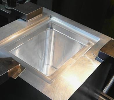
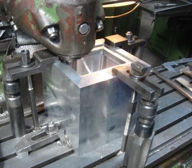
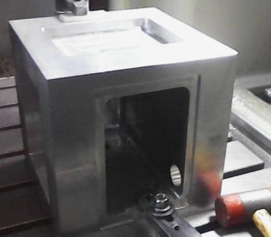
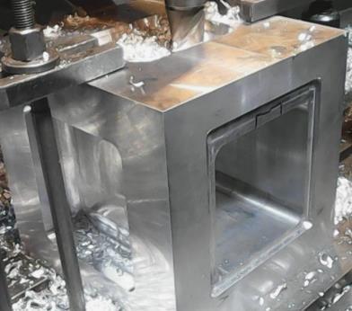
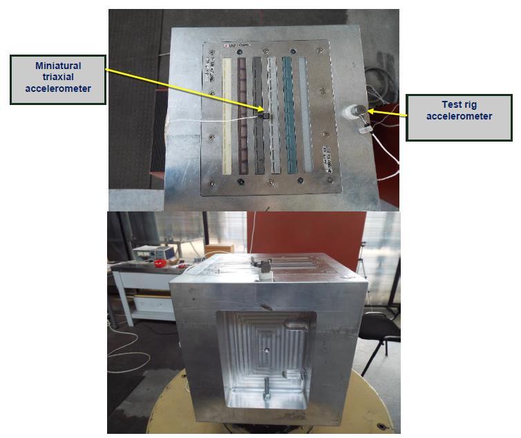
6 Design & Manufacturing of the test Rig Installation & Instrumentation of the Tile 6
7 Test No 1. External Control of the Actuator Panel The external control of the actuator panel (consist in) 1. Dimensional verification: Overall size; Operational size. 2. Weighting of the aggregate. Components -SJ Actuator panel 1 row of 5 slots with 30 exit angle 1 row of 5 slots with 45 exit angle - HJ Actuators panel: 1 row - Dummy; 1 row of 10 slots with 30 exit angle Bluestone; 1 row of 10 slots with 30 exit angle Aluminum; - ALM ISSUES 1 row of 10 slots with 30 exit angle Titanium; - ALM ISSUES 1 row of 10 slots with 30 exit angle Formlabs HT; 1 row of 10 slots with 30 exit angle PerFORM ; 7


8 Test No 1. External Control for SJ Actuator Panel SJ actuators panel design by FRAUN; - Test rig actuators panel designed by INCAS; 8


9 Test No 1. External Control of the Actuator Panel HJ actuators panel design by AGI; - Test rig for HJ actuators panel designed by INCAS; - Mounting of the HJ actuators panel on the test rig. 9
 Measurements will be made for each slot individually, taking into account the system performance and spatial resolution, in a continuous pass across the")
10 Test No 2. Functional Parameters (Normal Conditions) Measurements will be made for each slot individually, taking into account the system performance and spatial resolution, in a continuous pass across the length of the slot; In order to account for the flow geometry, we shall place the probes at a starting position of 4 mm from the slot and 8 mm above it, and take a pass at room temperature, and then modifying the distance we will try to find the most interesting flow profile (maximum speed or maximum speed variation). 10
 Hot Wire The PerFORM slots were supplied with compressed air")
11 Test No 2. Functional Parameters (PerFORM) Hot Wire The PerFORM slots were supplied with compressed air at 1 bar (control stage at 1 bar and drive stage at 1,2 bar) normal temperature 11
 Hot Wire The")

12 Test No 2. Functional Parameters (Formlabs) Hot Wire The Formlabs slots were supplied with compressed air at 1 bar (control stage at 1 bar and drive stage at 1,2 bar) normal temperature. 12
 Hot Wire The")

13 Test No 2. Functional Parameters (Bluestone) Hot Wire The Bluestone slots were supplied with compressed air at 0.6 bar normal temperature the inclination angle of the hot wire was


14 Test No 2. Functional Parameters - Pitot Tube The Pitot tube was aligned for air velocity baseline measurements at 15 incidence Measurements were made for each slot individually in a continuous pass along the length of the slot. In order to account for the flow geometry, we placed the probes at the following positions see table Bluestone, Formlabs and PerFORM pulsed jets 14


")
15 Test No 2. - Normal temperature Functional Parameters (Bluestone) Pitot Tube 15


")
16 Test No 2. Normal temperature Functional Parameters (Formlabs) Pitot Tube 16

17 Test No 2. Normal temperature Functional Parameters (PerFORM) Pitot Tube 17
.")
18 Test No 3. Extreme Temperatures - OK The actuators panel was installed on a dedicated test bench-interface. The entire assembly is placed into an enclosure where the working temperature is established at C (EUROCAE ED-14G, Section 4.5.4). Climatic test chamber: Ilka STBV-1000 Temperature control ± C Max vacuum. 1.5 Torr (reachable in ½ h ) Test chamber volume: 1 m³ Test chamber length: 1.16 m Test chamber width: 1.0 m Test chamber height: 0.84 m Nominated temperature levels was maintained for 1 hour to stabilize the temperature. 18
 The actuator was visually inspected and weighted before its placement in the climatic chamber test rig and equipped with temperature sensors to monitor its")
19 Test No 3. Extreme Temperatures-low temperature (1) The actuator was visually inspected and weighted before its placement in the climatic chamber test rig and equipped with temperature sensors to monitor its surface temperature Mass of the actuator before the test m i = 3310,88g Ambient temperature around climatic chamber before test = 26 C Relative humidity around climatic chamber before test = 28,25% Initial climatic chamber average temperature = 24,5 C 19
 After the one hour exposure at -55 C temperature, the climatic chamber door was opened (while the ventilator was still working to assure an uniform")
20 Test No 3. Extreme Temperatures-low temperature (2) After the one hour exposure at -55 C temperature, the climatic chamber door was opened (while the ventilator was still working to assure an uniform distribution of temperature in the environment around the actuator) to visually inspect the device surface and record images of the setup. After reaching ambient temperature the actuators panel was removed from the test rig and visually inspected and weighted. There were no changes or deformations observed in the device test rig or insulating material. Mass of the actuator after the test m= g Ambient temperature around climatic chamber after test T= C Relative humidity around climatic chamber after test RH= 28.68%. 20
 Aerodynamic measurements after low temperature test Measurements were made for each slot individually, taking into account the system performance and spatial")
21 Test No 3. Extreme Temperatures-low temperature (3) Aerodynamic measurements after low temperature test Measurements were made for each slot individually, taking into account the system performance and spatial resolution, in a continuous pass along the length of the slot. We placed the probes at a incidence 15o and take a pass at 100 C temperature, and then modifying the geometry configuration of Pitot tube, we tried to find the most interesting flow profile (maximum speed or maximum speed variation). 21
 The actuator was visually inspected and weighted before its placement in the climatic chamber test rig and equipped with temperature sensors to monitor its")
22 Test No 3. Extreme Temperatures-high temperature (1) The actuator was visually inspected and weighted before its placement in the climatic chamber test rig and equipped with temperature sensors to monitor its surface temperature Mass of the actuator before the test m i = 3310,88g Ambient temperature around climatic chamber before test = 23,95 C Relative humidity around climatic chamber before test = 41,11% Initial climatic chamber average temperature = 24,2 C 22
 After the one hour exposure of the device at 70 C the climatic chamber door was opened for visual inspection after which the environment was left to cool")
23 Test No 3. Extreme Temperatures-high temperature (2) After the one hour exposure of the device at 70 C the climatic chamber door was opened for visual inspection after which the environment was left to cool slowly until it reached ambient temperature to avoid thermal shocks. The device was removed from the test rig and visually inspected to see any changes after the high temperature test. No changes of the actuators or insulating material degradation were observed. Mass of the actuator after the test m= g Ambient temperature around climatic chamber after test T=25.76 C Relative humidity around climatic chamber after test RH=35.4 % 23
 Aerodynamic measurements after low temperature test Measurements were made for each slot individually, taking into account the system performance and spatial")
24 Test No 3. Extreme Temperatures-high temperature (3) Aerodynamic measurements after low temperature test Measurements were made for each slot individually, taking into account the system performance and spatial resolution, in a continuous pass along the length of the slot. We placed the probes at a incidence 15deg and take a pass at 100 C temperature, and then modifying the geometry configuration of Pitot tube, we tried to find the most interesting flow profile (maximum speed or maximum speed variation). Air velocity measurements with Pitot tube were made for each slot individually, taking into account the system performance and spatial resolution, in a continuous pass along the length of the slot. We placed the probes at a starting position: 1, 1.5 and 2 mm from the slot and 10 mm above it then 1, 1.5 and 2 mm from the slot and 15 mm above it and take a pass at 100 C temperature. 24


25 Test No 4. Artificial Rain - OK Testing of operational parameters under artificial rain conditions aims to verify if there is any risk of water penetration inside the actuators panel. The test is performed according to EUROCAE ED-14G standard, Section The actuators panel is installed on a suitable holder in a similar fitting position and with similar mechanical connections as on the aircraft. The actuators panels are supplied with 230 V AC for electronical components. 25


26 Test No 5. Icing Exposure -n OK The icing test aims to determine to what extent the actuators panel is affected by the ice formation and it is performed according to Section , EUROCAE ED-14G standard; The HJ actuators panel is thoroughly cleaned in order to remove the elements that affect adhesion between ice and its surface (such as oil, grease, dirt). 26

27 Test No 5. Icing Exposure Observation: After visual inspection, this test has reveal the fact that plastic material is influenced by the icing accretion on the thinnest side of the actuators nozzle wall. 27

28 Test No 6. Mechanical Vibrations - OK The actuators panel was tested in the frequency domain Hz, with a sweep rate not greater than 1 octave/min. The accelerometers signal recorded a level of accelerations Also, the actuators panel was NOT operational during the mechanical shock test. 28

29 Test No 7. Mechanical Shock - OK The test is performed on a mechanical shocks testing-machine. The actuators panel is fitted with the same gripping as on the aircraft, in a device that allows it s positioning so that the force resulting from the shock exposure manifests in one of the 6 directions derived from movements in planes parallel to the coordinate axes planes of the airplane. This test is based on EUROCAE ED-14G standard, Section 7. TIRA SHOCK 4110: Frequency range: Hz; Maximum load: 100 kg; Maximum acceleration: 570 m/s²; Maximum stroke: 20 mm; The input shock is measured by an accelerometer, placed as close as possible to the actuators panel attachment point, with an accuracy of ±10% of standard reading. 29

30 Test No 7. Mechanical Shock Recommendation: The test is performed on a mechanical shocks testing-machine. The actuators panel is fitted in a device that allows it s positioning so that the force resulting from the shock exposure manifests in one of the 6 directions derived from movements in planes parallel to the coordinate axes planes of the airplane. This test is based on EUROCAE ED-14G standard, Section 7. The input shock was measured by an accelerometer, placed as close as possible to the actuators panel attachment point, with an accuracy of ±10% of standard reading. 30


31 Test No 8. De-Icing Fluid This test determine whether the materials used in the construction of the equipment can withstand the un-wanted effects of fluid contamination. This test was based on EUROCAE ED-14G standard, Section 11. The actuators panel was installed on a specialized test bench and the equipment was not required to operate during this test and the test was performed at ambient temperature. The actuators panel is sprayed for minimum 15 minutes to the entire surface with De-Icing fluid Safewing MP II FLIGHT, a propylene glycol based SAE type II aircraft deicing / anti-icing fluid, which meets or exceeds the current revision of SAE specification AMS The flow of De-Icing fluid for spraying the actuators panel was Q = 200g/min. The surfaces were maintained in a wetted condition for 8 hours followed by a drying period of 16 hours at 65 C. 31

32 Test No 9. Solid Elements Contamination Half of the output windows of the actuators panel was completely blocked and the tests were performed wrt EUROCAE ED-14G standard. Bodies of A type were placed in all active rooms of the actuators panel final stage through the exit slots. Then the actuators panel was supplied by pressure. It was kept running for 30 minutes or until the complete elimination of the elements inserted into the actuators panel. This step was repeated by replacing Type A bodies with Type B and Type C. 32


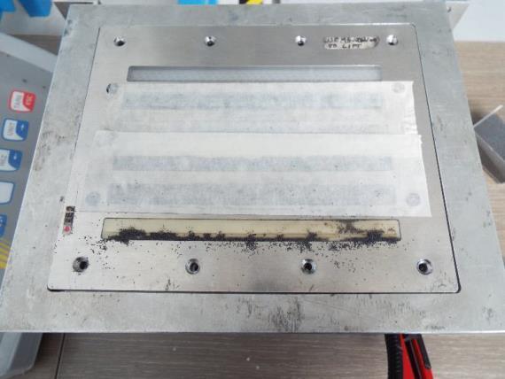
33 Test No 9. Solid Elements Contamination nok 33


34 Test No 10. Sand and Dust Exposure 34
35 Test No 10. Sand and Dust Exposure 35
36 Conclusions and Outlook In general the harsh environmental testing went well, some problems were encountered during the solid contamination/sand and dust tests; Specific care might be necessary for sand and dust conditions, since the essential feature of the active flow approach is a powerful control jets expelled out of a small orifice. Any blocking and/or remaining material inside the chamber could impact the functionality. We can conclude in general that the harsh environmental testing provided very valuable and detailed data sets, to compare the SJA /HJ properties before and after exposure to harsh conditions. 36
37 Thank you! Eng. Ionut BRINZA Bucharest, ROMANIA This project has received funding from the European Union s Seventh Framework Programme for research, technological development and demonstration under grant agreement No , AFLONEXT project. 37
Evaluation of High Lift System with Oscillatory Blowing in 2.5D Configuration
 Evaluation of High Lift System with Oscillatory Blowing in 2.5D Configuration Cǎtǎlin NAE, Mihai-Victor PRICOP Corresponding author INCAS - National Institute for Aerospace Research Elie Carafoli Bdul
The HumiSys. RH Generator. Operation. Applications. Designed, built, and supported by InstruQuest Inc.
 The HumiSys RH Generator Designed, built, and supported by InstruQuest Inc. Versatile Relative Humidity Generation and Multi-Sensor System The new HumiSys with single or dual RH probes capabilities is
AEROSPACE STANDARD. Minimum Operational Performance Specification for Inflight Icing Detection Systems FOREWORD
 400 Commonwealth Drive, Warrendale, PA 15096-0001 AEROSPACE STANDARD Issued 2001-10 Minimum Operational Performance Specification for Inflight Icing Detection Systems FOREWORD 1. The development of these
May08 Rev B
 Qualification Test Report 0.64 mm Generation Y Terminal 501-657 20May08 Rev B 1. INTRODUCTION 1.1. Purpose Testing was performed on the Tyco Electronics 0.64 mm Generation Y Terminal to determine its conformance
TR Test Report Complementary Testing RKN e1 Container (+5 C) Protection by Insulation Version: 01 Page: 2 (22)
 Protection by Insulation Version: 01 Page: 2 (22)") RKN e1 Container (+5 C) Protection by Insulation Version: 01 Page: 2 (22) Document History Version Date of issue Revision(s) Issued by 01 16OCT2012 N/A (First version of document) David Graaf, Envirotainer
RKN e1 Container (+5 C) Protection by Insulation Version: 01 Page: 2 (22) Document History Version Date of issue Revision(s) Issued by 01 16OCT2012 N/A (First version of document) David Graaf, Envirotainer
PRODUCT SPECIFICATION. SFP+ Cage and Cage Assembly 1 of 8 A
 SFP+ Cage and Cage Assembly 1 of 8 A 1.0 Objective This specification defines the performance, test, quality and reliability requirements of the _Small Form-factor Pluggage (SFP+) product. 2.0 Scope This
HumiSys HF High Flow RH Generator
 HumiSys HF High Flow RH Generator Designed, built, and supported by InstruQuest Inc. Versatile Relative Humidity Generation and Multi-Sensor System The HumiSys HF is a high flow version of the previously
«DO160/ED14» - Jessica France
 Training Workshop «DO160/ED14» - Jessica France DO160/ED14 Specificities of Mechanical and Climatic aspects Edouard ZUNDEL Systems Qualification Engineer for Mechanical and Climatic aspects 1 The reference
AF100. Subsonic Wind Tunnel AERODYNAMICS. Open-circuit subsonic wind tunnel for a wide range of investigations into aerodynamics
 Open-circuit subsonic wind tunnel for a wide range of investigations into aerodynamics Page 1 of 4 Works with Computer, chair and work table shown for photographic purposes only (not included) Screenshot
Gas density monitor With integrated transmitter Model GDM-100-TI
 SF 6 gas solutions Gas density monitor With integrated transmitter Model GDM-100-TI grid Products WIKA data sheet SP 60.05 for further approvals see page 5 Applications Gas density monitoring of closed
Ice Protection System
 Cirrus Design Section 9 Pilot s Operating Handbook and FAA Approved Airplane Flight Manual Supplement for Ice Protection System When the Ice Protection System is installed on the Cirrus Design, this POH
Subsonic Wind Tunnel 300 mm
 aerodynamics AF1300 An open circuit suction subsonic wind tunnel with a working section of 300 mm by 300 mm and 600 mm long Screenshot of the optional VDAS software Saves time and money compared to full-scale
Level MEASUREMENT 1/2016
 Level MEASUREMENT 1/2016 AGENDA 2 A. Introduction B. Float method C. Displacer method D. Hydrostatic pressure method E. Capacitance method G. Ultrasonic method H. Radar method I. Laser method J. Level
FPG8601 Force Balanced Piston Gauge
 FPG8601 Force Balanced Piston Gauge Reference Level Calibration System for very low pressure Pressure range: 0 to 15 kpa gauge, absolute and absolute differential Standard resolution: 0.010 Pa, high resolution
Application Note AN-107
 SPEC Sensor TM Characterization & Calibration Considerations Scope This document is provided to describe the considerations needed to characterize, calibrate, verify and validate the measurement performance
MIL-STD-883G METHOD
 STEADY-STATE LIFE 1. PURPOSE. The steady-state life test is performed for the purpose of demonstrating the quality or reliability of devices subjected to the specified conditions over an extended time
Customer Responsibilities. Important Customer Information Series Q-TOF LC/MS Systems Site Preparation Checklist
 Thank you for purchasing an Agilent system. To get you started and to assure a successful and timely installation, please refer to this specification or set of requirements. Correct site preparation is
IEP SENSOR BRACKET CHECKOUT AND VERIFICATION. This is a non-hazardous test.
 Page 1 of 20 NEXT GENERATION GAS SYSTEM (NGGS ) IEP SENSOR BRACKET CHECKOUT AND VERIFICATION PROCEDURE 870-PROC-623 Revision A Goddard Space Flight Center Greenbelt, Maryland 20771 FEBRUARY 13, 2002 This
Product Specification Spring Finger
 Product Specification 108-115008-3 Spring Finger Restricted to Sony Ericsson Mobile Communications 1. SCOPE 1.1. Content This specification covers the requirements for product performance test methods
Technical Data Sheet MF010-O-LC
 Technical Data Sheet MF010-O-LC - 1 - 1. Properties The oxygen measuring system MF010-O-LC determines the oxygen content in gas mixtures up to a temperature of 250 C. It is particularly suitable for the
Subsonic Wind Tunnel 300 mm
 aerodynamics AF1300 TecQuipment s AF1300 Subsonic Wind Tunnel. See also AF300S starter set that includes AF1300Z Basic Lift and Drag Balance and a set of AF1300J Three Dimensional Drag Models with the
VACUUM REGULATORS CONTENTS
 CAD drawing data catalog is available. ACCESSORIES GENERAL CATALOG AIR TREATMENT, AUXILIARY, VACUUM, AND FLUORORESIN PRODUCTS CONTENTS Small Regulators Features 759 Specifications, Order Codes, Flow Rate
Pressure transmitters EMP 2
 Data sheet Pressure transmitters EMP 2 The high accuracy pressure transmitter EMP 2 is designed for monitoring and control in marine and industial applications and offers a reliable pressure measurement,
Hydraulic Punch Drivers
 INSTRUCTION MANUAL 7804SB / 7806SB Quick Draw 7704SB / 7706SB Quick Draw Flex 7904SB / 7906SB Quick Draw 90 Quick Draw Hydraulic Punch Drivers Serial Codes AHJ, YZ, and ZA Read and understand all of the
Built-in Purge Control Functions
 Built-in Purge Control Functions Why clean a sensor? As the velocity sensor was calibrated clean, operating it clean also preserves the best calibration. Any build up of material on a thermal sensor tends
Schilling Robotics TITAN 4 Manipulator
 PRODUCT DATASHEET SUBSEA TECHNOLOGIES Schilling Robotics TITAN 4 Manipulator We put you first. And keep you ahead. Thousands of our manipulator systems are in use worldwide every day. TITAN manipulators
Investigation on Divergent Exit Curvature Effect on Nozzle Pressure Ratio of Supersonic Convergent Divergent Nozzle
 RESEARCH ARTICLE OPEN ACCESS Investigation on Divergent Exit Curvature Effect on Nozzle Pressure Ratio of Supersonic Convergent Divergent Nozzle Shyamshankar.M.B*, Sankar.V** *(Department of Aeronautical
Training Workshop «DO160/ED14» - Jessica France
 Training Workshop «DO160/ED14» - Jessica France DO160/ED14 Issue F to G Edouard ZUNDEL Systems Qualification Engineer for Mechanical and Climatic aspects 1 Overview - Temperature &Altitude Procedure clarification
Pro-V Multivariable Flowmeter Model M22 In-line Vortex
 Pro-V Multivariable Flowmeter Model M22 In-line Vortex Pro-V TM Advantage: Volumetric or mass flow monitoring of most liquids, gases, and steam Multivariable meter delivers mass flow, temperature, pressure,
LOW PRESSURE VOLTAGE BREAKDOWN TEST PROCEDURE FOR GSS FSU FLIGHT SPARE HVA BOARD October 28, P0938 Rev
 W. W. Hansen Experimental Physics Laboratory STANFORD UNIVERSITY STANFORD, CALIFORNIA 94305-4085 Gravity Probe B Relativity Mission LOW PRESSURE VOLTAGE BREAKDOWN TEST PROCEDURE FOR GSS FSU FLIGHT SPARE
WELCOME TO THE REVOLUTION
 USER GUIDE WELCOME TO THE REVOLUTION THANK YOU FOR CHOOSING THE GCQUAD We listened to what you wanted - and created the most accurate, versatile and game-enhancing ball and club analysis solution available
Calibration Procedure
 Management Procedure 2557 Revision: B Date Issued: September 20, 2016 Date Revised: March 13, 2018 Calibration Procedure PosiTector SST Soluble Salt Tester Table of Contents 1 Introduction and UUC Performance
Design DSA Steam-Atomized Desuperheater
 Instruction Manual DSA Desuperheater Design DSA Steam-Atomized Desuperheater Contents Introduction............................... 1 Scope of Manual......................... 1 Description..............................
ASDX Series Silicon Pressure Sensors
 ASDX Series Silicon Pressure Sensors DESCRIPTION The ASDX Series is a Silicon Pressure Sensor offering a ratiometric analog interface for reading pressure over the specified full scale pressure span and
CONTENTS 1. INTRODUCTION DESCRIPTION OF TEST SAMPLE TEST RIG GENERAL ARRANGEMENT TEST SEQUENCE...7
 Page 2 of 22 CONTENTS 1. INTRODUCTION...3 2. DESCRIPTION OF TEST SAMPLE...4 3. TEST RIG GENERAL ARRANGEMENT...6 4. TEST SEQUENCE...7 5. SUMMARY AND CLASSIFICATION OF TEST RESULTS...8 6. WATERTIGHTNESS
780S Ultra High Purity Series
 Smart Ultra High Purity Thermal Gas Mass Flow Meter Features Measures mass flow directly, no seperate temperature or pressure inputs required Field adjustment of critical flow meter settings via on-board
QUALIFICATION ENVIRONMENTS FOR AMP PROGRAM PROPELLANT TANK ALLIANT TECHSYSTEMS, P/N 80520
 QUALIFICATION ENVIRONMENTS FOR AMP PROGRAM PROPELLANT TANK ALLIANT TECHSYSTEMS, P/N 80520 ATK P/N 80520 Table 1: P/N 80520 Propellant Tank Specifications Parameters Requirements Operating Pressure Proof
Test Plans & Test Results
 P09051 Oxygen Gas Sensor Test Plans & Test Results By: Samuel H Shin (EE), Jeremy Goodman (ue) Table of contents 1. TITLE: OXYGEN MEASUREMENT TEST VIA FABRICATED OXYGEN GAS SENSOR SYSTEM... 2 1.1. Introduction...
HUMOR 20. High Accuracy Humidity Calibrator. Water T, p1 HUMOR 20 V1.0
 High Accuracy Humidity Calibrator The role of humidity calibrations that are accurate, reproducible, and documentable is becoming more and more important. ISO quality guidelines and regulations according
High-speed pressure sensor Model CPT6140
 Calibration technology High-speed pressure sensor Model CPT6140 WIKA data sheet CT 25.11 Applications Testing technology Calibration technology Laboratories and maintenance shops Leak and burst applications
OPERATIONAL TEST OF SONIC WIND SENSORS AT KNMI
 OPERATIONAL TEST OF SONIC WIND SENSORS AT KNMI Wiel M.F. Wauben 1 and Rob van Krimpen 2 1 R&D Information and Observation Technology, 2 Observation Systems Operations Royal Netherlands Meteorological Institute
Series Environmental Chambers
 3119-600 Series Environmental Chambers Challenges in Non-Ambient Testing Testing at non-ambient temperatures adds another layer of challenges to your testing laboratory. Ensuring you get accurate and stable
Maintenance handbook
 Maintenance handbook ontents HPU IDENTIFIATION SHEET... 4 1. MAINTENANE... 5 1.1 Filling level... 5 1.2 Fluid top-up... 5 1.3 Fluid replacing... 5 1.4 Fluid temperature control... 6 1.5 Functional control...
Vortex Flow Meter Wafer or Flange Connection. - Steam - Liquid - Gas
 Vortex Flow Meter Wafer or Flange Connection - Steam - Liquid - Gas Working Principle & Circuit Diagram Working Principle When a column body placed in flowing fluids in pipe, a series of vortices will
Qualification of Fastrak & First Gen Product to Railway applications Shock and Vibration Standard EN 61373
 Qualification of Fastrak & First Gen Product to Railway applications Shock and Vibration Standard EN 61373 (Governing Standard BS EN 5155 Railway Applications Electronic equipment used on rolling stock)
TransPort PT878GC Panametrics Portable Gas Ultrasonic Flowmeter. GE Sensing. Applications. Features
 Applications The TransPort PT878GC clamp-on gas flowmeter is a complete ultrasonic flow metering system for measurement of most gases, including: Natural gas Compressed air Fuel gases Erosive gases Corrosive
analytical bulk flow distance FLOW level pressure temperature industrial communication
 analytical bulk flow distance level pressure temperature industrial communication isolv THERMAL MASS METER Measuring Principle Self-heated Sensor Reference Sensor isolv Thermal Mass Flow Meters have two
C-Flow Coriolis Mass Flow Meters
 Coriolis Mass Flow Meters Ready for Take Off The New Compact C-Flow Küppers Elektromechanik GmbH The C-Flow The C-Flow Coriolis Mass Meters consist of two components: KCE Transmitter KCM Transducer 2 KEM
DC/DC Converter. Test item description...:
 age 2 of 24 Report No. 131200395SHA-001 Test item description...: Trade Mark...: Manufacturer...: Model and/or Type reference...: Rating(s)...: DC/DC Converter GlobTek GlobTek, Inc. GTD93035L6013.2-F,
TIGHTNESS. Glass sealing Thanks to our glass-sealing technology, ODU products can meet the most demanding tightness requirements.
 TIGHTNESS Glass sealing Thanks to our glass-sealing technology, ODU products can meet the most demanding tightness requirements. ODU has the necessary expertise for developing and manufacturing connectors
DIVERLESS SUBSEA HOT TAPPING OF PRODUCTION PIPELINES
 DIVERLESS SUBSEA HOT TAPPING OF PRODUCTION PIPELINES Dale Calkins Senior Project Engineer, TD Williamson Inc Biography Dale Calkins joined TD Williamson Inc in November of 1999 after working as a consulting
6000 SERIES OF PNEUMATIC DEADWEIGHT TESTERS
 6000 SERIES OF PNEUMATIC DEADWEIGHT TESTERS USER MANUAL -1- SI-BARNET DEADWEIGHT TESTER 6000 SERIES Release: S31-0250 Revision: A Date: 05/08/03 MANUFACTURED BY: GE RUSKA RUSKA INSTRUMENT CORPORATION 10311
TEMPERATURE GRADIENT PLATE MFFT 10 / MFFT 20 VF9700 / VF9600
 TEMPERATURE GRADIENT PLATE MFFT 10 / MFFT 20 VF9700 / VF9600 PRODUCT DESCRIPTION The new designed temperature gradient plate for measuring the Minimum Film Forming Temperature, MFFT BUSINESS Laboratories,
Instrumentation & Data Acquisition Systems
 Instrumentation & Data Acquisition Systems Section 3 -Level Robert W. Harrison, PE Bob@TheHarrisonHouse.com Made in USA 1 Level Section Question Which level measuring technology is the best solution when
Inflatable Packer Single & Double. Single & Double Packer Dimension. Wireline Packer. Water Testing Packer (WTP) Packer
 Packer") Inflatable Packer Single & Double Single & Double Packer Dimension Wireline Packer Water Testing Packer (WTP) Packer Packer Working Pressure & Depth Chart Packer Water Hand Pump Packer Air Driven Pump
Inflatable Packer Single & Double Single & Double Packer Dimension Wireline Packer Water Testing Packer (WTP) Packer Packer Working Pressure & Depth Chart Packer Water Hand Pump Packer Air Driven Pump
Customer Responsibilities. Important Customer Information. Cary 4000/5000/6000i UV-Vis spectrophotometer Site Preparation Checklist
 Thank you for purchasing an Agilent instrument. To get you started and to assure a successful and timely installation, please refer to this specification or set of requirements. Correct site preparation
Electronic gas volume corrector model DGVC-04
 Electronic gas volume corrector model DGVC-04 1. Introduction The following user s manual gives information about the installation, configuration, usage and storage of the electronic gas volume corrector
HZ-300 HAZER MACHINE USER MANUAL. Congratulations on the purchase of your new ANTARI HZ-300 Haze Machine.
 HZ-300 HAZER MACHINE USER MANUAL Congratulations on the purchase of your new ANTARI HZ-300 Haze Machine. Read and save these instructions 2005 Antari Lighting and Effects Ltd 2 User Manual Antari HZ-300
LUGB Vortex Flowmeter
 LUGB Vortex Flowmeter Overview LUGB swirl flowmeter is also called as vortex flowmeter, it is a new of flowmeter which is developed according to fluid vibration theory, widely used for fluid measurement
Title: Standard Operating Procedure for R&R Environmental Devices Model MFC201 Gas Dilution Calibrator
 Procedure No: SOP-029 Revision No: 1.1 (December 29, 2010) Page No.: 1 of 7 1. INTRODUCTION AND SCOPE To obtain timely data for the purpose of air quality assessment, air quality trend reporting, air quality
WARNING: EXPLOSION HAZARD
 Section 1 Safety 1.1 Instructions for the Safe Operation and Use of the Pulse Oximeter Do not attempt to service the Pulse Oximeter yourself. Only qualified service personnel should attempt any necessary
WBEA Standard Operating Procedure
 Page 1 WBEA Standard Operating Procedure SOP Title Temperature and Relative Humidity Author Gary Cross Implementation date March 2, 2013 Revision History Revision # Date Description Author Page 2 Table
Miris Ultrasonic Processor
 Installation Qualification & Operational Qualification Figure 1. The 1. Sound reducing cabinet 2. Power supply unit Miris AB Kungsgatan 115 753 18 UPPSALA SWEDEN Tel: +46 18 14 69 07 e-mail: support@mirissolutions.com
Design of a Solid Wall Transonic Wind Tunnel
 Design of a Solid Wall Transonic Wind Tunnel David Wall * Auburn University, Auburn, Alabama, 36849 A solid wall transonic wind tunnel was designed with optical access from three sides to allow for flow
Translation Principles of testing and certification for insulating hose assemblies on cable cutting devices
 Translation Principles of testing and certification for insulating hose assemblies on cable cutting devices Status as of 2014-01 Principles of testing Insulating hose assemblies on cable cutting devices
The HumiPyc - Model 1 - Gas Pycnometer; Density, Moisture, Permeation Analyzer; RH sensor Calibrator
 The HumiPyc - Model 1 - Gas Pycnometer; Density, Moisture, Permeation Analyzer; RH sensor Calibrator Designed, built, and supported by InstruQuest Inc. Temperature controlled, multi-technique volumetric
Saab Seaeye Cougar XT Compact
 The Seaeye Cougar-XT Compact is a highly flexible and extremely powerful electric ROV with working depths of 300 metres. This system comes with almost all of the specifications of the very reliable Couger-XT
Intertek Testing Services Taiwan Ltd.
 1) The testing results relate only to the items tested. Page 2 of 21 2) The test report shall not be reproduced except in full, without written approval of the laboratory. 3) This test report only allows
Pneumatic high-pressure controller Model CPC7000
 Calibration technology Pneumatic high-pressure controller Model CPC7000 WIKA data sheet CT 27.63 Applications Healthcare and avionics industry Industry (laboratory, workshop and production) Transmitter
Fiber Cable Puller with Tuf-Lugger lite
 7 OPERATING INSTRUCTION MANUAL Fiber Cable Puller with Tuf-Lugger lite Copyright 2015 DCD Design & Manufacturing Ltd. Revision 1.0 IMPORTANT SAFETY INSTRUCTIONS READ ALL INSTRUCTIONS BEFORE USING The Fiber
Pressure reducing valve, pilot operated, Model 3DR
 RA 26 928/06.98 Pressure reducing valve, pilot operated, Model 3DR Nominal size 16 Series 5X Maximum operating pressure 3600 PSI (250 bar) Maximum flow 58.1 GPM (220 L/min) Contents Description Page Features
Specific Accreditation Criteria Calibration ISO IEC Annex. Mass and related quantities
 Specific Accreditation Criteria Calibration ISO IEC 17025 Annex Mass and related quantities January 2018 Copyright National Association of Testing Authorities, Australia 2014 This publication is protected
Specifications for Synchronized Sensor Pipe Condition Assessment (AS PROVIDED BY REDZONE ROBOTICS)
") Specifications for Synchronized Sensor Pipe Condition Assessment (AS PROVIDED BY REDZONE ROBOTICS) A. Scope of Work The work covered by these specifications consists of furnishing all materials, labor,
Specifications for Synchronized Sensor Pipe Condition Assessment (AS PROVIDED BY REDZONE ROBOTICS) A. Scope of Work The work covered by these specifications consists of furnishing all materials, labor,
The Faraday Test Centre Rochester
 Rochester REAL CAPABILITY. REAL ADVANTAGE. BAE Systems is an international company engaged in the development, delivery and support of advanced defence and aerospace systems in the air, on land, at sea
MANUAL KPS Pressure Control Valve
 TetraTec Instruments GmbH Gewerbestrasse 8 71144 Steinenbronn Deutschland E-Mail: info@tetratec.de Tel.: 07157/5387-0 Fax: 07157/5387-10 MANUAL Pressure Control Valve *** VERSION 1.0 *** Update: 17.11.2006
AF101 to AF109. Subsonic Wind Tunnel Models AERODYNAMICS. A selection of optional models for use with TecQuipment s Subsonic Wind Tunnel (AF100)
") Page 1 of 4 A selection of optional models for use with TecQuipment s Subsonic Wind Tunnel (AF100) Dimpled Sphere Drag Model (from AF109) shown inside the TecQuipment AF100 Wind Tunnel. Cylinder, aerofoils,
Page 1 of 4 A selection of optional models for use with TecQuipment s Subsonic Wind Tunnel (AF100) Dimpled Sphere Drag Model (from AF109) shown inside the TecQuipment AF100 Wind Tunnel. Cylinder, aerofoils,
SIMULATION OF ENVIRONMENTAL FLIGHT CONDITIONS
 SIMULATION OF ENVIRONMENTAL FLIGHT CONDITIONS BY ADVANCED ALTITUDE SIMULATION Klaus SCHÄFER Institute of Space Propulsion, German Aerospace Centre (DLR) Lampoldshausen, 74239 Hardthausen, Germany klaus.schaefer@dlr.de
Smoke and heat Ventilator Testing
 Instituut vir Termodinamika en Meganika Institute for Thermodynamics and Mechanics Smoke and heat Ventilator Testing by CJ Zietsman and GR Smith November 2005 Departement Meganiese Ingenieurswese Privaat
TECHNICAL DATA. Q = C v P S
 January 6, 2012 Preaction 348a 1. Description Viking supervised Surefire Preaction Systems utilize the Viking G-6000P Valve. The small profile, lightweight, pilot operated Viking G-6000P Valve comes complete
Enhancing aircraft corrosion risk management via microclimate simulation
 Enhancing aircraft corrosion risk management via microclimate simulation Dr Milan Patel, Prof Ivan Cole RMIT University 6 th July 2018 Aircraft Airworthiness & Sustainment Australia Conference Brisbane
TECHNICAL DATA. Q = C v P S
 January 6, 2012 Preaction 333a 1. Description Viking supervised Surefire Preaction Systems Utilize the Viking G-3000P Valve. The small profile, lightweight, pilot-operated Viking G-3000P Valve comes complete
HUMOR 20 HUMOR 20. High-precision Humidity Calibrator. Water T, p1
 High-precision Humidity Calibrator The role of humidity calibrations that are accurate, reproducible, and documentable is becoming more and more important. ISO quality guidelines and regulations according
Title: Standard Operating Procedure for The Tapered Element Oscillating Microbalance (TEOM)
") Procedure No: SOP-004 Revision No: 2.0 ( August 2009) Page No.: 1 of 12 1. INTRODUCTION AND SCOPE The Tapered Element Oscillating provides real time mass measurement of selected size particles in ambient
Procedure No: SOP-004 Revision No: 2.0 ( August 2009) Page No.: 1 of 12 1. INTRODUCTION AND SCOPE The Tapered Element Oscillating provides real time mass measurement of selected size particles in ambient
Certified according to DIN EN ISO 9001 Technical Datasheet TRICOR Series Mass Flow Meters
 www.kem-kueppers.com info@kem-kueppers.com Certified according to DIN EN ISO 9001 Technical Datasheet TRICOR Series Mass Flow Meters Description The Tricor Mass Flow Meters measure simultaneously mass
Impact of imperfect sealing on the flow measurement of natural gas by orifice plates
 Impact of imperfect sealing on the flow measurement of natural gas by orifice plates Rubens Silva Telles 1, Kazuto Kawakita 2 1 IPT Instituto de Pesquisas Tecnológicas, São Paulo, Brazil, rtelles@ipt.br
Vortex Meters for Liquids, Gas, and Steam
 A Measuring Principle Comes of Age: Vortex Meters for Liquids, Gas, and Steam Dipl.-Hyd. Oliver Seifert, Product Management Vortex Meters at Flowtec AG, and Ellen-Christine Reiff, M.A., Editor s Office,
RATE CONTROL SYSTEM FOR SOUNDING ROCKETS
 RATE CONTROL SYSTEM FOR SOUNDING ROCKETS Josef Ettl, Johann Pfänder German Aerospace Center (DLR), D-834 Wessling, Germany e-mail: josef.ettl@dlr.de johann.pfaender@dlr.de, 1. ABSTRACT DLR/Moraba has a
PZN-plus. Application example. Pneumatic 3-Finger Centric Gripper Universal Gripper. Sizes Gripping force 580 N..
 PZN-plus Sizes 40.. 300 Weight 0.43 kg.. 43.5 kg Gripping force 580 N.. 38000 N Stroke per finger 3 mm.. 35 mm Workpiece weight 2.9 kg.. 190 kg Application example Insertion tool for assembling small to
PRESSURE TRANSDUCERS WITH UNIFIED (4-20) ma OR (10-50) ma OUTPUT SIGNAL
 ma OR (10-50) ma OUTPUT SIGNAL") PRESSURE TRANSDUCERS WITH UNIFIED (4-0) ma OR (10-50) ma OUTPUT SIGNAL 4 th Draft OIML Recommendation TC10-SC1 English version 4.0 Prepared by: Mgr. Jiří Tesař, PhD., Mgr. Dominik Pražák Pressure Department
PRESSURE TRANSDUCERS WITH UNIFIED (4-0) ma OR (10-50) ma OUTPUT SIGNAL 4 th Draft OIML Recommendation TC10-SC1 English version 4.0 Prepared by: Mgr. Jiří Tesař, PhD., Mgr. Dominik Pražák Pressure Department
AC : ACCURATE CRYOCHAMBER FOR A SMALL LABORATORY WITH SMALL BUDGET
 AC 2007-1108: ACCURATE CRYOCHAMBER FOR A SMALL LABORATORY WITH SMALL BUDGET Matthew Braley, University of Idaho Paul Anderson, University of Idaho Tracey Windley, University of Idaho Kevin Buck, University
Programmable Submersible Level Transmitters
 Programmable Submersible Level Transmitters PTM/N/RS485 CUSTOMER BENEFITS High flexibility due to scalalbe pressure range Digital (RS485) and analogue (4-20mA) output signal in one sensor Available as
WMO LABORATORY INTERCOMPARISON OF RAIN INTENSITY GAUGES
 WMO LABORATORY INTERCOMPARISON OF RAIN INTENSITY GAUGES Christophe ALEXANDROPOULOS and Muriel LACOMBE Météo-France, Direction des Systèmes d Observation, BP 202-78195 Trappes France christophe.alexandropoulos@meteo.fr
TECHNICAL DATA. Q = C v P S
 January 6, 2012 Preaction 331a 1. Description Viking supervised Double-Interlocked Electric/Pneumatic Release Preaction Systems utilize the Viking G-3000P Valve. The small profile, lightweight, pilot-operated
ESAIL D3.1.1 Requirement specifications of the tether test reels
 D3.1.1 Requirement specifications of the tether test reels Work Package: WP 3.1 Version: Version 1.0 Prepared by: DLR German Aerospace Center, Olaf Krömer, Roland Rosta Time: Bremen, May 30 th, 2011 Coordinating
HYDRAULICS. H89.8D - Hydraulic Bench
 HYDRAULICS H89.8D - Hydraulic Bench 1. General The H89.8D and ancillary equipment have been developed to provide a comprehensive range of experiments in fluid mechanics. The bench is of robust construction
Mod. M M M063..
 CATALOGUE > Release 8.6 > Pressure gauges Pressure gauges Mod. M04.. - M05.. - M06.. Precision classes CL1,6 and CL2,5» Radial connection» Rear connection» Panel mounting To select the most suitable pressure
MTS Restan. Automatic System for Residual Stress Measurement by Hole-Drilling
 Automatic System for Residual Stress The MTS3000 - Restan system for measuring residual stresses Fully automatic drilling and acquisition process ensuring high repeatability High speed drilling (400,000
Rheological properties. Rheological instruments backed with rheological experience. Malvern. detailed specification sheets from
 Rheological properties ṙ Rheological instruments backed with rheological experience detailed specification sheets from www.malvern.com/rosand Malvern Advanced bench-top capillary rheometers for research,
DeFelsko PosiTector CMM IS Probe
 Management Procedure 2566 Revision: A Date Issued: January 23, 2018 Date Revised: Calibration Procedure DeFelsko PosiTector CMM IS Probe Table of Contents 1 Introduction and UUC Performance Requirements...
TransPort PT878GC Panametrics Ultrasonic Portable Gas Flowmeter. GE Infrastructure Sensing. Features. Applications
 Applications The TransPort PT878GC clamp-on gas flowmeter is a complete ultrasonic flow metering system for measurement of most gases, including: Natural gas Compressed air Fuel gases Erosive gases Corrosive