Qualification of Fastrak & First Gen Product to Railway applications Shock and Vibration Standard EN 61373
|
|
|
- Silvia Phelps
- 6 years ago
- Views:
Transcription
 Dated")
1 Qualification of Fastrak & First Gen Product to Railway applications Shock and Vibration Standard EN (Governing Standard BS EN 5155 Railway Applications Electronic equipment used on rolling stock) Dated 5/1/6
2 Qualification of Fastrak & First Gen Product to Railway applications Shock and Vibration Standard EN PURPOSE: To demonstrate compliance of Vicor product to the environmental (EN ), shock and vibration (EN 61373) standards from EN 5155, the European Standard for electronic equipment used in Railway applications. 2. EXECUTIVE SUMMARY: Representative DC-DC power conversion modules were selected from both the Fastrak and First Gen platforms. VI-81423B was selected from Fastrak and VI-2T3-CU from First Gen. Each group was tested as outlined below to demonstrate compliance to EN Both groups successfully completed the testing with no deterioration in the performance of the modules as demonstrated in the test results. 3 REQUIREMENTS: 3.1 Test Samples: 15 pieces of VI-81423B were selected from the Fastrak product line and 15 pieces of VI-2T3-CU were selected as representative samples from the 1 st Generation product line. 3.2 Production Requirements: All test samples will be manufactured with the standard process. 3.3 Testing Requirements: All modules must be tested on the standard production ATE tester for that specific model, passing all tests before initiating qualification testing. During qualification testing the product must operate as outlined in the test requirement. Upon the completion of each test set each module must be tested to verify that there are no electrical failures. Each module must also be visually inspected to verify that there are no visual defects. Page 2 of 12 Pages
3 Qualification of Fastrak & First Gen Product to Railway applications Shock and Vibration Standard EN Definition of Electrical Failure: A failure will be a module that changes in electrical performance (parameters outside acceptable tolerance limits of specification) or other criteria specific to an environmental test. If the cause of the failure is caused by fixture failure or operator error it will not be counted as a failure. 4 TEST SEQUENCE 1. Initial Electrical Performance Test At Rated Operating Temperatures: Test Method: Functional ATE test. 2. Shock & Vibration Test: Test performed at outside LAB The report from the outside Lab has been added to the end of this report. Test Condition: Test Parameters: Nominal input voltage, no load, output monitored to verify continuous operation. Random Vibration: Category <.3Kg Freq range: 5grms: 5hrs per axis Shock: Long./Trans./Vert. Axis Peak acceleration:5g/2g/1g Duration: 5ms/ 2ms/ 2ms. 3. Electrical Performance Tests At Rated Operational Temperatures: Test Method: Functional ATE test Page 3 of 12 Pages
4 Qualification of Fastrak & First Gen Product to Railway applications Shock and Vibration Standard EN Temperature/Relative Humidity Test Test Condition: Non-biased. Test Parameters Time 1 hours Temperature 55 C Relative Humidity 95%RH 5. Operating Temperature Test Test Condition: Nominal Input Full load, continuous operation. Test Parameters Time 8 hrs Temperature 85 C for 6 hrs followed by 2 hrs at 4 C 6. Electrical Performance Tests At Rated Operational Temperatures: Test Method: Functional ATE test. Page 4 of 12 Pages
5 Qualification of Fastrak & First Gen Product to Railway applications Shock and Vibration Standard EN TEST DATA VI-2T3- CU Vibration And Shock Test Results CONTINUATION / RELIABILITY ENGINEERING DEPARTMENT RANDOM VIBRATION: (5GRMS 5-15HZ) SHOCK: (1G 2MS, 2G 2MS, 5G 5MS) ENG TECHNICIAN: EDWARD MEJIA / NATIONAL TECHNICAL SYSTEMS MODEL NUMBER: VI-2T3-CU Y AXIS Serial # Date V HR 1 V HR 2 V HR 3 V HR 4 V HR 5 S 1G+ S 1G- S 2G+ S 2G- S 5G+ S 5G /15/26 PASS PASS PASS PASS PASS PASS PASS PASS PASS PASS PASS /15/26 PASS PASS PASS PASS PASS PASS PASS PASS PASS PASS PASS /15/26 PASS PASS PASS PASS PASS PASS PASS PASS PASS PASS PASS /15/26 PASS PASS PASS PASS PASS PASS PASS PASS PASS PASS PASS /17/26 PASS PASS PASS PASS PASS PASS PASS PASS PASS PASS PASS /17/26 PASS PASS PASS PASS PASS PASS PASS PASS PASS PASS PASS /17/26 PASS PASS PASS PASS PASS PASS PASS PASS PASS PASS PASS /17/26 PASS PASS PASS PASS PASS PASS PASS PASS PASS PASS PASS /17/26 PASS PASS PASS PASS PASS PASS PASS PASS PASS PASS PASS /17/26 PASS PASS PASS PASS PASS PASS PASS PASS PASS PASS PASS /17/26 PASS PASS PASS PASS PASS PASS PASS PASS PASS PASS PASS /17/26 PASS PASS PASS PASS PASS PASS PASS PASS PASS PASS PASS /17/26 PASS PASS PASS PASS PASS PASS PASS PASS PASS PASS PASS /17/26 PASS PASS PASS PASS PASS PASS PASS PASS PASS PASS PASS /17/26 PASS PASS PASS PASS PASS PASS PASS PASS PASS PASS PASS Page 5 of 12 Pages
6 Qualification of Fastrak & First Gen Product to Railway applications Shock and Vibration Standard EN VI-2T3-CU VI-2T3- CU Vibration And Shock Test Results - Continued X AXIS Serial # Date V HR 1 V HR 2 V HR 3 V HR 4 V HR 5 S 1G+ S 1G- S 2G+ S 2G- S 5G+ S 5G /2/26 PASS PASS PASS PASS PASS PASS PASS PASS PASS PASS PASS /2/26 PASS PASS PASS PASS PASS PASS PASS PASS PASS PASS PASS /2/26 PASS PASS PASS PASS PASS PASS PASS PASS PASS PASS PASS /2/26 PASS PASS PASS PASS PASS PASS PASS PASS PASS PASS PASS /2/26 PASS PASS PASS PASS PASS PASS PASS PASS PASS PASS PASS /2/26 PASS PASS PASS PASS PASS PASS PASS PASS PASS PASS PASS /2/26 PASS PASS PASS PASS PASS PASS PASS PASS PASS PASS PASS /2/26 PASS PASS PASS PASS PASS PASS PASS PASS PASS PASS PASS /2/26 PASS PASS PASS PASS PASS PASS PASS PASS PASS PASS PASS /2/26 PASS PASS PASS PASS PASS PASS PASS PASS PASS PASS PASS /2/26 PASS PASS PASS PASS PASS PASS PASS PASS PASS PASS PASS /2/26 PASS PASS PASS PASS PASS PASS PASS PASS PASS PASS PASS /2/26 PASS PASS PASS PASS PASS PASS PASS PASS PASS PASS PASS /2/26 PASS PASS PASS PASS PASS PASS PASS PASS PASS PASS PASS /2/26 PASS PASS PASS PASS PASS PASS PASS PASS PASS PASS PASS VI-2T3-CU Z AXIS Serial # Date V HR 1 V HR 2 V HR 3 V HR 4 V HR 5 S 1G+ S 1G- S 2G+ S 2G- S 5G+ S 5G /21/26 PASS PASS PASS PASS PASS PASS PASS PASS PASS PASS PASS /21/26 PASS PASS PASS PASS PASS PASS PASS PASS PASS PASS PASS /21/26 PASS PASS PASS PASS PASS PASS PASS PASS PASS PASS PASS /21/26 PASS PASS PASS PASS PASS PASS PASS PASS PASS PASS PASS /21/26 PASS PASS PASS PASS PASS PASS PASS PASS PASS PASS PASS /21/26 PASS PASS PASS PASS PASS PASS PASS PASS PASS PASS PASS /21/26 PASS PASS PASS PASS PASS PASS PASS PASS PASS PASS PASS /21/26 PASS PASS PASS PASS PASS PASS PASS PASS PASS PASS PASS /21/26 PASS PASS PASS PASS PASS PASS PASS PASS PASS PASS PASS /21/26 PASS PASS PASS PASS PASS PASS PASS PASS PASS PASS PASS /21/26 PASS PASS PASS PASS PASS PASS PASS PASS PASS PASS PASS /21/26 PASS PASS PASS PASS PASS PASS PASS PASS PASS PASS PASS /21/26 PASS PASS PASS PASS PASS PASS PASS PASS PASS PASS PASS /21/26 PASS PASS PASS PASS PASS PASS PASS PASS PASS PASS PASS /21/26 PASS PASS PASS PASS PASS PASS PASS PASS PASS PASS PASS Page 6 of 12 Pages
7 Qualification of Fastrak & First Gen Product to Railway applications Shock and Vibration Standard EN VI-2T3- CU ATE Test Data Start Date Result Testkind Part Number Serial Number ::1 Device Passed Functional Test VI-2T3-CV :11:11 Device Passed Functional Test VI-2T3-CV :25:7 Device Passed Functional Test VI-2T3-CV :1:21 Device Passed Functional Test VI-2T3-CV :1:6 Device Passed Functional Test VI-2T3-CV :23:3 Device Passed Functional Test VI-2T3-CV :59:35 Device Passed Functional Test VI-2T3-CV :9:44 Device Passed Functional Test VI-2T3-CV :25:8 Device Passed Functional Test VI-2T3-CV :59:22 Device Passed Functional Test VI-2T3-CV :12:58 Device Passed Functional Test VI-2T3-CV :23:29 Device Passed Functional Test VI-2T3-CV :55:2 Device Passed Functional Test VI-2T3-CV :12:31 Device Passed Functional Test VI-2T3-CV :18:33 Device Passed Functional Test VI-2T3-CV :56:24 Device Passed Functional Test VI-2T3-CV :1:58 Device Passed Functional Test VI-2T3-CV :22:38 Device Passed Functional Test VI-2T3-CV :2:12 Device Passed Functional Test VI-2T3-CV :13:18 Device Passed Functional Test VI-2T3-CV :17:2 Device Passed Functional Test VI-2T3-CV :44:11 Device Passed Functional Test VI-2T3-CV :12:18 Device Passed Functional Test VI-2T3-CV :2:32 Device Passed Functional Test VI-2T3-CV Page 7 of 12 Pages
8 Qualification of Fastrak & First Gen Product to Railway applications Shock and Vibration Standard EN Start Date Result Testkind Part Number Serial Number :44:52 Device Passed Functional Test VI-2T3-CV :12:45 Device Passed Functional Test VI-2T3-CV :24:42 Device Passed Functional Test VI-2T3-CV :44:23 Device Passed Functional Test VI-2T3-CV :11:41 Device Passed Functional Test VI-2T3-CV :2:36 Device Passed Functional Test VI-2T3-CV :45:17 Device Passed Functional Test VI-2T3-CV :13:27 Device Passed Functional Test VI-2T3-CV :22:26 Device Passed Functional Test VI-2T3-CV :47:56 Device Passed Functional Test VI-2T3-CV :1:3 Device Passed Functional Test VI-2T3-CV :23:55 Device Passed Functional Test VI-2T3-CV :47:7 Device Passed Functional Test VI-2T3-CV :12:6 Device Passed Functional Test VI-2T3-CV :19:29 Device Passed Functional Test VI-2T3-CV :48:32 Device Passed Functional Test VI-2T3-CV :1:46 Device Passed Functional Test VI-2T3-CV :2:51 Device Passed Functional Test VI-2T3-CV :46:43 Device Passed Functional Test VI-2T3-CV :11:53 Device Passed Functional Test VI-2T3-CV :21:42 Device Passed Functional Test VI-2T3-CV Page 8 of 12 Pages
9 Qualification of Fastrak & First Gen Product to Railway applications Shock and Vibration Standard EN VI-81423B Vibration And Shock Test Results - CONTINUATION / RELIABILITY ENGINEERING DEPARTMENT RANDOM VIBRATION: (5G RMS 5-15HZ) SHOCK: (1G 2MS, 2G 2MS, 5G 5MS) ENG TECHNICIAN: EDWARD MEJIA / NATIONAL TECHNICAL SYSTEMS MODEL NUMBER: VI-81423B Y AXIS Serial # Date V HR 1 V HR 2 V HR 3 V HR 4 V HR 5 S 1G+ S 1G- S 2G+ S 2G- S 5G+ S 5G /28/26 PASS PASS PASS PASS PASS PASS PASS PASS PASS PASS PASS /22/26 PASS PASS PASS PASS PASS PASS PASS PASS PASS PASS PASS /22/26 PASS PASS PASS PASS PASS PASS PASS PASS PASS PASS PASS /22/26 PASS PASS PASS PASS PASS PASS PASS PASS PASS PASS PASS /22/26 PASS PASS PASS PASS PASS PASS PASS PASS PASS PASS PASS /27/26 PASS PASS PASS PASS PASS PASS PASS PASS PASS PASS PASS /24/26 PASS PASS PASS PASS PASS PASS PASS PASS PASS PASS PASS /26/26 PASS PASS PASS PASS PASS PASS PASS PASS PASS PASS PASS /22/26 PASS PASS PASS PASS PASS PASS PASS PASS PASS PASS PASS /23/26 PASS PASS PASS PASS PASS PASS PASS PASS PASS PASS PASS /22/26 PASS PASS PASS PASS PASS PASS PASS PASS PASS PASS PASS /22/26 PASS PASS PASS PASS PASS PASS PASS PASS PASS PASS PASS /22/26 PASS PASS PASS PASS PASS PASS PASS PASS PASS PASS PASS /22/26 PASS PASS PASS PASS PASS PASS PASS PASS PASS PASS PASS /25/26 PASS PASS PASS PASS PASS PASS PASS PASS PASS PASS PASS VI-81423B X AXIS Serial # Date V HR 1 V HR 2 V HR 3 V HR 4 V HR 5 S 1G+ S 1G- S 2G+ S 2G- S 5G+ S 5G /23/26 PASS PASS PASS PASS PASS PASS PASS PASS PASS PASS PASS /23/26 PASS PASS PASS PASS PASS PASS PASS PASS PASS PASS PASS /23/26 PASS PASS PASS PASS PASS PASS PASS PASS PASS PASS PASS /23/26 PASS PASS PASS PASS PASS PASS PASS PASS PASS PASS PASS /23/26 PASS PASS PASS PASS PASS PASS PASS PASS PASS PASS PASS /23/26 PASS PASS PASS PASS PASS PASS PASS PASS PASS PASS PASS /24/26 PASS PASS PASS PASS PASS PASS PASS PASS PASS PASS PASS /24/26 PASS PASS PASS PASS PASS PASS PASS PASS PASS PASS PASS /24/26 PASS PASS PASS PASS PASS PASS PASS PASS PASS PASS PASS /24/26 PASS PASS PASS PASS PASS PASS PASS PASS PASS PASS PASS /24/26 PASS PASS PASS PASS PASS PASS PASS PASS PASS PASS PASS /24/26 PASS PASS PASS PASS PASS PASS PASS PASS PASS PASS PASS /24/26 PASS PASS PASS PASS PASS PASS PASS PASS PASS PASS PASS /24/26 PASS PASS PASS PASS PASS PASS PASS PASS PASS PASS PASS /24/26 PASS PASS PASS PASS PASS PASS PASS PASS PASS PASS PASS Page 9 of 12 Pages
10 Qualification of Fastrak & First Gen Product to Railway applications Shock and Vibration Standard EN VI-81423B Vibration And Shock Test Results - Continued Z AXIS Serial # Date V HR 1 V HR 2 V HR 3 V HR 4 V HR 5 S 1G+ S 1G- S 2G+ S 2G- S 5G+ S 5G /1/26 PASS PASS PASS PASS PASS PASS PASS PASS PASS PASS PASS /1/26 PASS PASS PASS PASS PASS PASS PASS PASS PASS PASS PASS /1/26 PASS PASS PASS PASS PASS PASS PASS PASS PASS PASS PASS /1/26 PASS PASS PASS PASS PASS PASS PASS PASS PASS PASS PASS /1/26 PASS PASS PASS PASS PASS PASS PASS PASS PASS PASS PASS /1/26 PASS PASS PASS PASS PASS PASS PASS PASS PASS PASS PASS /1/26 PASS PASS PASS PASS PASS PASS PASS PASS PASS PASS PASS /1/26 PASS PASS PASS PASS PASS PASS PASS PASS PASS PASS PASS /1/26 PASS PASS PASS PASS PASS PASS PASS PASS PASS PASS PASS /1/26 PASS PASS PASS PASS PASS PASS PASS PASS PASS PASS PASS /1/26 PASS PASS PASS PASS PASS PASS PASS PASS PASS PASS PASS /2/26 PASS PASS PASS PASS PASS PASS PASS PASS PASS PASS PASS /2/26 PASS PASS PASS PASS PASS PASS PASS PASS PASS PASS PASS /2/26 PASS PASS PASS PASS PASS PASS PASS PASS PASS PASS PASS /2/26 PASS PASS PASS PASS PASS PASS PASS PASS PASS PASS PASS Page 1 of 12 Pages
11 Qualification of Fastrak & First Gen Product to Railway applications Shock and Vibration Standard EN VI-81423B Test Data Start Date Bin Testkind Part Number Serial Number :23:56 Device Passed Functional Test VI-81423B :43:54 Device Passed Functional Test VI-81423B :47:46 Device Passed Functional Test VI-81423B :11:45 Device Passed Functional Test VI-81423B :42:16 Device Passed Functional Test VI-81423B :52:11 Device Passed Functional Test VI-81423B :22:25 Device Passed Functional Test VI-81423B :55:7 Device Passed Functional Test VI-81423B :42:38 Device Passed Functional Test VI-81423B :23:13 Device Passed Functional Test VI-81423B :54:23 Device Passed Functional Test VI-81423B :37:3 Device Passed Functional Test VI-81423B :25:15 Device Passed Functional Test VI-81423B :47:38 Device Passed Functional Test VI-81423B :5:42 Device Passed Functional Test VI-81423B :24:18 Device Passed Functional Test VI-81423B :58:5 Device Passed Functional Test VI-81423B :46:25 Device Passed Functional Test VI-81423B :21:1 Device Passed Functional Test VI-81423B :57:18 Device Passed Functional Test VI-81423B :4:31 Device Passed Functional Test VI-81423B :17:28 Device Passed Functional Test VI-81423B :45:43 Device Passed Functional Test VI-81423B :44:29 Device Passed Functional Test VI-81423B :2:19 Device Passed Functional Test VI-81423B :56:17 Device Passed Functional Test VI-81423B :23:35 Device Passed Functional Test VI-81423B ::45 Device Passed Functional Test VI-81423B :39:17 Device Passed Functional Test VI-81423B :22:37 Device Passed Functional Test VI-81423B :51:6 Device Passed Functional Test VI-81423B :48:31 Device Passed Functional Test VI-81423B Page 11 of 12 Pages
12 Qualification of Fastrak & First Gen Product to Railway applications Shock and Vibration Standard EN Start Date Bin TestKind Part Number Serial Number :19:39 Device Passed Functional Test VI-81423B :59:36 Device Passed Functional Test VI-81423B :57:47 Device Passed Functional Test VI-81423B :19:16 Device Passed Functional Test VI-81423B :5:1 Device Passed Functional Test VI-81423B :44:48 Device Passed Functional Test VI-81423B :2:35 Device Passed Functional Test VI-81423B :41:12 Device Passed Functional Test VI-81423B :59:42 Device Passed Functional Test VI-81423B :24:56 Device Passed Functional Test VI-81423B :46:43 Device Passed Functional Test VI-81423B :42:48 Device Passed Functional Test VI-81423B Page 12 of 12 Pages
13 Test Report No. TR E, Rev. Vibration and Shock Testing of Power Supplies Prepared For: Vicor Corporation 4 Federal Street Andover, MA 181 P.O. Number: SEV Prepared By: National Technical Systems 1146 Massachusetts Avenue Boxborough, MA 1719 (978) Issued: March 17, 26 This report and the information contained herein represent the results of testing articles/products identified and selected by the client. The tests were performed to specifications and/or procedures approved by the client. National Technical Systems ( NTS ) makes no representations expressed or implied that such testing fully demonstrates efficiency, performance, reliability, or any other characteristic of the articles being tested, or similar products. This report should not be relied upon as an endorsement or certification by NTS of the equipment tested, nor does it represent any statement whatsoever as to its merchantability or fitness of the test article or similar products for a particular purpose. This document shall not be reproduced except in full without written approval from National Technical Systems ( NTS ). 1 of 68
14 Revision Page Rev. No Date Page No. Para. No. Description Original March 17, 26 2 of 68
15 Signatures Prepared by Erin K. Reilly, Technical Writer Approved by Steven Goodman, Program Manager Reviewed by NTS Quality Representative 3 of 68
16 Table of Contents 1. Purpose References Test Items Description Security Classification of Items Test Dates and Equipment Test Dates Test Equipment Test Descriptions and Results Test Summary Random Vibration Test Shock Test...9 Appendices Appendix A Test Equipment List... A-1 Appendix B...B-1 Appendix C Notices of Deviation... C-1 4 of 68
17 1. Purpose This report presents the test procedures used and the results obtained during the performance of a Vibration and Shock test program. The test program was conducted to assess the ability of 3 Power Supplies to successfully satisfy the requirements specified in the references listed in Section 2. of this report. 2. References 2.1 Vicor Corporation Purchase Order Number SEV dated December 2, NTS Quotation Number B-115E dated December 2, ISO/IEC 1725:25(E), General Requirements for the Competence of Testing and Calibration Laboratories, May 15, British Standard BS EN 5155:21, Railway Applications Electronic Equipment Used on Rolling Stock, dated August Test Items 3.1 Description Qty. Item P/N S/N 15 Power Supply VI-2T3-CU N/A 15 Power Supply VI B N/A 3.2 Security Classification of Items Unclassified 4. Test Dates and Equipment 4.1 Test Dates February and March 2, Test Equipment A list of the test equipment used is included in Appendix A of this report. This equipment is calibrated according to ISO/IEC 1725:25(E) and calibration is traceable to the National Institute of Standards and Technology (NIST). Calibration records are maintained on file at National Technical Systems. 5 of 68
18 5. Test Descriptions and Results The test items were inspected upon receipt at NTS. No damage was noted. All testing was performed in accordance with Section 2. of this test report. 5.1 Test Summary The Power Supplies met the requirements of Section 2. of this test report. There was no damage or deterioration following the Vibration and Shock test program. Four incidents of deviation occurred during Random Vibration testing. Test #5 in the X-axis was aborted at 36 minutes, 1 seconds. It was noted that the spanners on the piston had loosened during vibration. The spanners were tightened and testing continued. Reference Appendix C for Notice of Deviation Number D-1 dated February 2, 26. Test #5 in the X-axis was aborted at 38 minutes, 59 seconds. It was noted that two of the flange bolts on one side of the piston had broken, causing hydraulic oil to spray from the pit. The bolts were replaced and testing continued. Reference Appendix C for Notice of Deviation Number D-2 dated February 2, 26. Test #13 in the X-axis was aborted at 3 hours, 54 minutes, 11 seconds. A hairline crack was found near a weld on one of the flanges on the piston, causing hydraulic oil to spray from the pit. The flange was re-welded to cover the crack and testing continued. Reference Appendix C for Notice of Deviation Number D-3 dated February 22, 26. Test #21 in the Z-axis was aborted at 8 minutes, 36 seconds. Two of the flange bolts on one side of the piston had broken, causing hydraulic oil to spray from the pit. Testing at that point had been split-banded. Testing in the range from 2 Hz to 15 Hz was completed on the NTS T-4 Electrodynamic Shaker. Testing in the range from 5 Hz to 2 Hz was completed on the Electro-hydraulic Shaker. Reference Appendix C for Notice of Deviation D-4 dated February 24, 26. Reference Sections 5.2 through 5.3 for test details and Appendix B for Vibration and Shock test data. Test Section Reference Met Criteria: Y/N Random Vibration 5.2 British Standard BS EN 5155:21, Railway Applications Electronic Y Shock 5.3 Equipment Used on Rolling Stock, dated August 21 Y 6 of 68
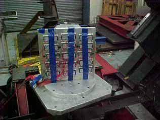
19 5.2 Random Vibration Test The Power Supplies, in an operating mode, were securely attached to a fixture plate, which was securely mounted to the Electro-hydraulic Shaker (the NTS T- 4 Electro-dynamic Shaker was used for one axis). One control accelerometer was located on the test fixture during all Random Vibration testing to monitor and record testing for later playback and plotting. The vibration system was programmed as follows: Table I: Random Vibration Test TEST PROFILE 5 grms Total 5 Hz to 15 g 2 /Hz 5 hours/axis Three mutually perpendicular axes Random Vibration Test Setup X-axis VI-2T3-CU X-axis VI B Y-axis VI-2T3-CU Y-axis VI B 7 of 68

20 Random Vibration Test Setup Z-axis VI-2T3-CU Z-axis VI B Z-axis VI B (T-4 Shaker) Comments The Power Supplies showed no damage or deterioration following the Random Vibration testing. Reference Appendix B for. Test #5 in the X-axis was aborted at 36 minutes, 1 seconds. It was noted that the spanners on the piston had loosened during vibration. The spanners were tightened and testing continued. Reference Appendix C for Notice of Deviation Number D-1 dated February 2, 26. Test #5 in the X-axis was aborted at 38 minutes, 59 seconds. It was noted that two of the flange bolts on one side of the piston had broken, causing hydraulic oil to spray from the pit. The bolts were replaced and testing continued. Reference Appendix C for Notice of Deviation Number D-2 dated February 2, of 68
21 Test #13 in the X-axis was aborted at 3 hours, 54 minutes, 11 seconds. A hairline crack was found near a weld on one of the flanges on the piston, causing hydraulic oil to spray from the pit. The flange was re-welded to cover the crack and testing continued. Reference Appendix C for Notice of Deviation Number D- 3 dated February 22, 26. Test #21 in the Z-axis was aborted at 8 minutes, 36 seconds. Two of the flange bolts on one side of the piston had broken, causing hydraulic oil to spray from the pit. Testing at that point had been split-banded. Testing in the range from 2 Hz to 15 Hz was completed on the NTS T-4 Electro-dynamic Shaker. Testing in the range from 5 Hz to 2 Hz was completed on the Electro-hydraulic Shaker. Reference Appendix C for Notice of Deviation D-4 dated February 24, Shock Test The Power Supplies, in an operating mode, were securely attached to a fixture plate, which was securely mounted to the NTS Electro-hydraulic Shaker. One control accelerometer was located on the test fixture during all Shock testing to monitor and record testing for later playback and plotting. The vibration system was programmed as follows: Table II: Mechanical Shock Test TEST PROFILE 1 g half-sine waveform 2 millisecond duration 1 shocks in each directions/axis 6 total shocks Three mutually perpendicular axes TEST PROFILE 5 g s half-sine waveform 5 millisecond duration 1 shocks in each directions/axis 6 total shocks Three mutually perpendicular axes 9 of 68


22 Shock Test Setup X-axis VI-2T3-CU X-axis VI B Y-axis VI-2T3-CU Y-axis VI B 1 of 68
23 Shock Test Setup Z-axis VI-2T3-CU Z-axis VI B Comments The Power Supplies showed no damage or deterioration following the Mechanical Shock testing. Reference Appendix B for. 11 of 68
24 Appendix A Test Equipment List A-1 of 68
25 Shortcut# Invent # Description/Manufacturer Model #/Serial # Range/Accuracy Frq/Due Dt Calibration Status AC454 PE44 EARTHQUAKE SIMULATOR 24.63S UWCE MTS SYSTEMS 11 AC789 AC647 ACCELEROMETER 353B33 1HZ TO 4KHZ 12 CAL PCB /-5% 7/1/6 AC1871 AC1871 VIBRATION CONTROLLER KHZ 12 CAL VIBRATION RESEARC 79cbb,38bfa, +/-2% 5-1 HZ 12/7/6 BX393 PE446E KEYBOARD C145A NCR HEWLETT PACKARD 328S53673 BX894 PE523 VIBRATION CONTROL SYSTEM 2552B TO 2 KHZ 6 CAL GENERAL RADIO D +/-1% 5/5/6 BX1677 ACCELEROMETER 353B17 1-1HZ, 1MV/G 6 CAL PCB PIEZOTRONICS /-5% 3/28/6 Calibration Abbreviations UWCE - use with calibrated equipment CBU - calibrate before use NQM - not used for quantitative measurement CAL - calibrated NCR - no calibration required A-2 of 68
26 Appendix B B-1 of 68
27 Data stored on February 17, 26 16:1:14 MJO# 3814 Vicor VI-2T3-CU (15) Test# 1 Axis: Z Random Vibration 5-15 Hz End of Test 1 1x1 Acceleration Profile - Loop 1 1x1 Acceleration (G²/Hz) -1 1x1-2 1x1 1x Frequency (Hz) B-2 of 68
28 Data stored on February 17, 26 16:1:14 MJO# 3814 Vicor VI-2T3-CU (15) Test# 1 Axis: Z Random Vibration 5-15 Hz Breakpoint table Frequency G²/Hz db/octave 5 Hz Hz.1725 Duration Level 1) 5:: 1 % ** Test started February 17, 26 11:1:2, running for 5:6:2 ** Current level: 1, running at 1 % for 5:: of 5:: : 5.37 G RMS : G RMS Ch1: G RMS Ch2: G RMS Ch3: G RMS Ch4: G RMS Drive voltage: Vrms in pk-pk in pk-pk Ch1 in-band: G RMS Ch2 in-band: G RMS Ch3 in-band: G RMS Ch4 in-band:.1393 G RMS System gain is Volts/G (Max system gain limit = 5) Ch1: 14.4 mv/g (75954, 8/7/5) Ch2: 13.9 mv/g (53972, 7/1/6) Ch3: 12.1 mv/g (5797, 1/26/6) Ch4: 12.3 mv/g (57976, 1/26/6) B-3 of 68
29 Data stored on February 17, 26 16:34:1 MJO# 3814 Vicor VI-2T3-CU (15) - Test# 2 Axis: Z Shock 1G 2ms Stop Button Pressed.5 Acce lera tion Acceleration (G) Time (ms) Test Profile: 2 ms Half Sine Pulse with amplitude 1 G (Negative) Pre-pulse amplitude: 1 % of the peak acceleration Post-pulse amplitude: 3 % of the peak acceleration Normal limits used channels: Pulses Level 1) 1 1 % (Memorized drive) ** Test started February 17, 26 16:33:54 ** Current level: 1, running at 1 % for of 1 pulses amplitude: G Output voltage: Volts peak Ch1: 14.4 mv/g (75954, 8/7/5) Ch2: 13.9 mv/g (53972, 7/1/6) Ch3: 12.1 mv/g (5797, 1/26/6) Ch4: 12.3 mv/g (57976, 1/26/6) B-4 of 68
30 Data stored on February 17, 26 16:32:18 MJO# 3814 Vicor VI-2T3-CU (15) - Test# 2 Axis: Z Shock 1G 2ms Starting with Memorized Drive 1.5 Acce lera tion 1. Acceleration (G) Test Profile: 2 ms Half Sine Pulse with amplitude 1 G (Positive) Pre-pulse amplitude: 1 % of the peak acceleration Post-pulse amplitude: 3 % of the peak acceleration Normal limits used channels: Time (ms) Pulses Level 1) 1 1 % (Memorized drive) ** Test started February 17, 26 16:31:51 ** Current level: 1, running at 1 % for of 1 pulses amplitude: G Output voltage: Volts peak Ch1: 14.4 mv/g (75954, 8/7/5) Ch2: 13.9 mv/g (53972, 7/1/6) Ch3: 12.1 mv/g (5797, 1/26/6) Ch4: 12.3 mv/g (57976, 1/26/6) B-5 of 68
31 Data stored on February 17, 26 16:36:55 MJO# 3814 Vicor VI-2T3-CU (15) - Test# 3 Axis: Z Shock 2G 2ms Stop Button Pressed 1. Acce lera tion.5 Acceleration (G) Time (ms) Test Profile: 2 ms Half Sine Pulse with amplitude 2 G (Negative) Pre-pulse amplitude: 1 % of the peak acceleration Post-pulse amplitude: 3 % of the peak acceleration Normal limits used channels: Pulses Level 1) 1 1 % (Memorized drive) ** Test started February 17, 26 16:36:35 ** Current level: 1, running at 1 % for of 1 pulses amplitude: G Output voltage: Volts peak Ch1: 14.4 mv/g (75954, 8/7/5) Ch2: 13.9 mv/g (53972, 7/1/6) Ch3: 12.1 mv/g (5797, 1/26/6) Ch4: 12.3 mv/g (57976, 1/26/6) B-6 of 68
32 Data stored on February 17, 26 16:36:21 MJO# 3814 Vicor VI-2T3-CU (15) - Test# 3 Axis: Z Shock 2G 2ms Stop Button Pressed 3. Acce lera tion Acceleration (G) Test Profile: 2 ms Half Sine Pulse with amplitude 2 G (Positive) Pre-pulse amplitude: 1 % of the peak acceleration Post-pulse amplitude: 3 % of the peak acceleration Normal limits used channels: Time (ms) Pulses Level 1) 1 1 % (Memorized drive) ** Test started February 17, 26 16:34:58 ** Current level: 1, running at 1 % for of 1 pulses amplitude: G Output voltage: Volts peak Ch1: 14.4 mv/g (75954, 8/7/5) Ch2: 13.9 mv/g (53972, 7/1/6) Ch3: 12.1 mv/g (5797, 1/26/6) Ch4: 12.3 mv/g (57976, 1/26/6) B-7 of 68
33 Data stored on February 17, 26 16:39:28 MJO# 3814 Vicor VI-2T3-CU (15) - Test# 4 Axis: Z Shock 5G 5ms Stop Button Pressed 4 Acce lera tion 2 Acceleration (G) Time (ms) Test Profile: 5 ms Half Sine Pulse with amplitude 5 G (Negative) Pre-pulse amplitude: 1 % of the peak acceleration Post-pulse amplitude: 3 % of the peak acceleration Normal limits used channels: Pulses Level 1) 1 1 % (Memorized drive) ** Test started February 17, 26 16:39:6 ** Current level: 1, running at 1 % for of 1 pulses amplitude: G Output voltage: Volts peak Ch1: 14.4 mv/g (75954, 8/7/5) Ch2: 13.9 mv/g (53972, 7/1/6) Ch3: 12.1 mv/g (5797, 1/26/6) Ch4: 12.3 mv/g (57976, 1/26/6) B-8 of 68
34 Data stored on February 17, 26 16:38:56 MJO# 3814 Vicor VI-2T3-CU (15) - Test# 4 Axis: Z Shock 5G 5ms Stop Button Pressed 8 Acce lera tion 6 Acceleration (G) Test Profile: 5 ms Half Sine Pulse with amplitude 5 G (Positive) Pre-pulse amplitude: 1 % of the peak acceleration Post-pulse amplitude: 3 % of the peak acceleration Normal limits used channels: Time (ms) Pulses Level 1) 1 1 % (Memorized drive) ** Test started February 17, 26 16:37:4 ** Current level: 1, running at 1 % for of 1 pulses amplitude: G Output voltage: Volts peak Ch1: 14.4 mv/g (75954, 8/7/5) Ch2: 13.9 mv/g (53972, 7/1/6) Ch3: 12.1 mv/g (5797, 1/26/6) Ch4: 12.3 mv/g (57976, 1/26/6) B-9 of 68
35 Data stored on Feb 21, 26 16:13:5 MJO# 3814 Vicor VI-2T3-CU (15) Test# 5 Axis: X Random Vibration 5-15 Hz End of Test 1 1x1 Acceleration Profile - Loop 1 1x1 Acceleration (G²/Hz) -1 1x1-2 1x1 1x Frequency (Hz) B-1 of 68
36 Data stored on Feb 21, 26 16:13:5 MJO# 3814 Vicor VI-2T3-CU (15) Test# 5 Axis: X Random Vibration 5-15 Hz Breakpoint table Frequency G²/Hz db/octave 5 Hz Hz.1725 Duration Level 1) 5:: 1 % ** Test started February 2, 26 9:34:54, running for 5:22:1 ** Current level: 1, running at 1 % for 5:: of 5:: : 5.37 G RMS : 5.12 G RMS Ch1: G RMS Ch2: G RMS Ch3: G RMS Ch4:.5854 G RMS Drive voltage: Vrms in pk-pk in pk-pk Ch1 in-band: G RMS Ch2 in-band: G RMS Ch3 in-band: G RMS Ch4 in-band: G RMS System gain is Volts/G (Max system gain limit = 5) Ch1: 14.4 mv/g (75954, 8/7/5) Ch2: 13.9 mv/g (53972, 7/1/6) Ch3: 12.1 mv/g (5797, 1/26/6) Ch4: 12.3 mv/g (57976, 1/26/6) B-11 of 68
37 Data stored on February 21, 26 16:18:41 MJO# 3814 Vicor VI-2T3-CU (15) - Test# 6 Axis: X Shock 1G 2ms Stop Button Pressed.5 Acce lera tion Acceleration (G) Time (ms) Test Profile: 2 ms Half Sine Pulse with amplitude 1 G (Negative) Pre-pulse amplitude: 1 % of the peak acceleration Post-pulse amplitude: 3 % of the peak acceleration Normal limits used channels: Pulses Level 1) 1 1 % (Memorized drive) ** Test started February 21, 26 16:18:2 ** Current level: 1, running at 1 % for of 1 pulses amplitude: G Output voltage: Volts peak Ch1: 14.4 mv/g (75954, 8/7/5) Ch2: 13.9 mv/g (53972, 7/1/6) Ch3: 12.1 mv/g (5797, 1/26/6) Ch4: 12.3 mv/g (57976, 1/26/6) B-12 of 68
38 Data stored on February 21, 26 16:17:49 MJO# 3814 Vicor VI-2T3-CU (15) - Test# 6 Axis: X Shock 1G 2ms Stop Button Pressed 1.5 Acce lera tion 1. Acceleration (G) Test Profile: 2 ms Half Sine Pulse with amplitude 1 G (Positive) Pre-pulse amplitude: 1 % of the peak acceleration Post-pulse amplitude: 3 % of the peak acceleration Normal limits used channels: Time (ms) Pulses Level 1) 1 1 % (Memorized drive) ** Test started February 21, 26 16:17:33 ** Current level: 1, running at 1 % for of 1 pulses amplitude: G Output voltage: Volts peak Ch1: 14.4 mv/g (75954, 8/7/5) Ch2: 13.9 mv/g (53972, 7/1/6) Ch3: 12.1 mv/g (5797, 1/26/6) Ch4: 12.3 mv/g (57976, 1/26/6) B-13 of 68
39 Data stored on February 21, 26 16:21:11 MJO# 3814 Vicor VI-2T3-CU (15) - Test# 7 Axis: X Shock 2G 2ms - Stop Button Pressed Acce lera tion 1 Acceleration (G) Time (ms) Test Profile: 2 ms Half Sine Pulse with amplitude 2 G (Negative) Pre-pulse amplitude: 1 % of the peak acceleration Post-pulse amplitude: 3 % of the peak acceleration Normal limits used channels: Pulses Level 1) 1 1 % (Memorized drive) ** Test started February 21, 26 16:2:55 ** Current level: 1, running at 1 % for of 1 pulses amplitude: G Output voltage: Volts peak Ch1: 14.4 mv/g (75954, 8/7/5) Ch2: 13.9 mv/g (53972, 7/1/6) Ch3: 12.1 mv/g (5797, 1/26/6) Ch4: 12.3 mv/g (57976, 1/26/6) B-14 of 68
40 Data stored on February 21, 26 16:2:44 MJO# 3814 Vicor VI-2T3-CU (15) - Test# 7 Axis: X Shock 2G 2ms - Stop Button Pressed 3. Acce lera tion Acceleration (G) Test Profile: 2 ms Half Sine Pulse with amplitude 2 G (Positive) Pre-pulse amplitude: 1 % of the peak acceleration Post-pulse amplitude: 3 % of the peak acceleration Normal limits used channels: Time (ms) Pulses Level 1) 1 1 % (Memorized drive) ** Test started February 21, 26 16:19:21 ** Current level: 1, running at 1 % for of 1 pulses amplitude: G Output voltage: Volts peak Ch1: 14.4 mv/g (75954, 8/7/5) Ch2: 13.9 mv/g (53972, 7/1/6) Ch3: 12.1 mv/g (5797, 1/26/6) Ch4: 12.3 mv/g (57976, 1/26/6) B-15 of 68
41 Data stored on February 21, 26 16:41:34 MJO# 3814 Vicor VI-2T3-CU (15) - Test# 8 Axis: X Shock 5G 5ms - Stop Button Pressed 6 Acce lera tion 4 2 Acceleration (G) Time (ms) Test Profile: 48 ms Half Sine Pulse with amplitude 5 G (Negative) Pre-pulse amplitude: 1 % of the peak acceleration Post-pulse amplitude: 3 % of the peak acceleration Normal limits used channels: Pulses Level 1) 1 1 % (Memorized drive) ** Test started February 21, 26 16:39:37 ** Current level: 1, running at 1 % for of 1 pulses amplitude: G Output voltage: Volts peak Ch1: 14.4 mv/g (75954, 8/7/5) Ch2: 13.9 mv/g (53972, 7/1/6) Ch3: 12.1 mv/g (5797, 1/26/6) Ch4: 12.3 mv/g (57976, 1/26/6) B-16 of 68
42 Data stored on February 21, 26 16:27:28 MJO# 3814 Vicor VI-2T3-CU (15) - Test# 8 Axis: X Shock 5G 5ms - Stop Button Pressed 8 Acce lera tion 6 4 Acceleration (G) Test Profile: 5 ms Half Sine Pulse with amplitude 5 G (Positive) Pre-pulse amplitude: 1 % of the peak acceleration Post-pulse amplitude: 3 % of the peak acceleration Normal limits used channels: Time (ms) Pulses Level 1) 1 1 % (Memorized drive) ** Test started February 21, 26 16:25:9 ** Current level: 1, running at 1 % for of 1 pulses amplitude: G Output voltage: Volts peak Ch1: 14.4 mv/g (75954, 8/7/5) Ch2: 13.9 mv/g (53972, 7/1/6) Ch3: 12.1 mv/g (5797, 1/26/6) Ch4: 12.3 mv/g (57976, 1/26/6) B-17 of 68
43 Data stored on February 21, 26 22:9:5 MJO# 3814 Vicor VI-2T3-CU (15) Test# 9 Axis: Y Random Vibration 5-15 Hz End of Test 1 1x1 Acceleration Profile - Loop 1 1x1 Acceleration (G²/Hz) -1 1x1-2 1x1 1x Frequency (Hz) B-18 of 68
44 Data stored on February 21, 26 22:9:5 MJO# 3814 Vicor VI-2T3-CU (15) Test# 9 Axis: Y Random Vibration 5-15 Hz Breakpoint table Frequency G²/Hz db/octave 5 Hz Hz.1725 Duration Level 1) 5:: 1 % ** Test started February 21, 26 17:5:2, running for 5:3:19 ** Current level: 1, running at 1 % for 5:: of 5:: : 5.37 G RMS : G RMS Ch1: G RMS Ch2: G RMS Ch3: G RMS Ch4: G RMS Drive voltage: Vrms in pk-pk in pk-pk Ch1 in-band: G RMS Ch2 in-band: G RMS Ch3 in-band: G RMS Ch4 in-band: G RMS System gain is Volts/G (Max system gain limit = 5) Ch1: 14.4 mv/g (75954, 8/7/5) Ch2: 13.9 mv/g (53972, 7/1/6) Ch3: 12.1 mv/g (5797, 1/26/6) Ch4: 12.3 mv/g (57976, 1/26/6) B-19 of 68
45 Data stored on February 22, 26 8:19:58 MJO# 3814 Vicor VI-2T3-CU (15) - Test# 1 Axis: Y Shock 1G 2ms Stop Button Pressed.5 Acce lera tion Acceleration (G) Time (ms) Test Profile: 2 ms Half Sine Pulse with amplitude 1 G (Negative) Pre-pulse amplitude: 1 % of the peak acceleration Post-pulse amplitude: 3 % of the peak acceleration Normal limits used channels: Pulses Level 1) 1 1 % (Memorized drive) ** Test started February 22, 26 8:19:32 ** Current level: 1, running at 1 % for of 1 pulses amplitude: G Output voltage: Volts peak Ch1: 14.4 mv/g (75954, 8/7/5) Ch2: 13.9 mv/g (53972, 7/1/6) Ch3: 12.1 mv/g (5797, 1/26/6) Ch4: 12.3 mv/g (57976, 1/26/6) B-2 of 68
46 Data stored on February 22, 26 8:19:16 MJO# 3814 Vicor VI-2T3-CU (15) - Test# 1 Axis: Y Shock 1G 2ms Stop Button Pressed 1.5 Acce lera tion 1. Acceleration (G) Test Profile: 2 ms Half Sine Pulse with amplitude 1 G (Positive) Pre-pulse amplitude: 1 % of the peak acceleration Post-pulse amplitude: 3 % of the peak acceleration Normal limits used channels: Time (ms) Pulses Level 1) 1 1 % (Memorized drive) ** Test started February 22, 26 8:18:46 ** Current level: 1, running at 1 % for of 1 pulses amplitude: G Output voltage:.8125 Volts peak Ch1: 14.4 mv/g (75954, 8/7/5) Ch2: 13.9 mv/g (53972, 7/1/6) Ch3: 12.1 mv/g (5797, 1/26/6) Ch4: 12.3 mv/g (57976, 1/26/6) B-21 of 68
47 Data stored on February 22, 26 8:22:13 MJO# 3814 Vicor VI-2T3-CU (15) - Test# 11 Axis: Y Shock 2G 2ms Stop Button Pressed Acce lera tion 1 Acceleration (G) Time (ms) Test Profile: 2 ms Half Sine Pulse with amplitude 2 G (Negative) Pre-pulse amplitude: 1 % of the peak acceleration Post-pulse amplitude: 3 % of the peak acceleration Normal limits used channels: Pulses Level 1) 1 1 % (Memorized drive) ** Test started February 22, 26 8:21:57 ** Current level: 1, running at 1 % for of 1 pulses amplitude: G Output voltage: Volts peak Ch1: 14.4 mv/g (75954, 8/7/5) Ch2: 13.9 mv/g (53972, 7/1/6) Ch3: 12.1 mv/g (5797, 1/26/6) Ch4: 12.3 mv/g (57976, 1/26/6) B-22 of 68
48 Data stored on February 22, 26 8:21:43 MJO# 3814 Vicor VI-2T3-CU (15) - Test# 11 Axis: Y Shock 2G 2ms Stop Button Pressed 3. Acce lera tion Acceleration (G) Test Profile: 2 ms Half Sine Pulse with amplitude 2 G (Positive) Pre-pulse amplitude: 1 % of the peak acceleration Post-pulse amplitude: 3 % of the peak acceleration Normal limits used channels: Time (ms) Pulses Level 1) 1 1 % (Memorized drive) ** Test started February 22, 26 8:21:24 ** Current level: 1, running at 1 % for of 1 pulses amplitude: G Output voltage: Volts peak Ch1: 14.4 mv/g (75954, 8/7/5) Ch2: 13.9 mv/g (53972, 7/1/6) Ch3: 12.1 mv/g (5797, 1/26/6) Ch4: 12.3 mv/g (57976, 1/26/6) B-23 of 68
49 Data stored on February 22, 26 8:29:34 MJO# 3814 Vicor VI-2T3-CU (15) - Test# 12 Axis: Y Shock 5G 5ms Stop Button Pressed 2 Acce lera tion Acceleration (G) Time (ms) Test Profile: 5 ms Half Sine Pulse with amplitude 5 G (Negative) Pre-pulse amplitude: 1 % of the peak acceleration Post-pulse amplitude: 3 % of the peak acceleration Normal limits used channels: Pulses Level 1) 1 1 % (Memorized drive) ** Test started February 22, 26 8:27:53 ** Current level: 1, running at 1 % for of 1 pulses amplitude: G Output voltage: Volts peak Ch1: 14.4 mv/g (75954, 8/7/5) Ch2: 13.9 mv/g (53972, 7/1/6) Ch3: 12.1 mv/g (5797, 1/26/6) Ch4: 12.3 mv/g (57976, 1/26/6) B-24 of 68
50 Data stored on February 22, 26 8:25:56 MJO# 3814 Vicor VI-2T3-CU (15) - Test# 12 Axis: Y Shock 5G 5ms Stop Button Pressed 8 Acce lera tion 6 4 Acceleration (G) Test Profile: 5 ms Half Sine Pulse with amplitude 5 G (Positive) Pre-pulse amplitude: 1 % of the peak acceleration Post-pulse amplitude: 3 % of the peak acceleration Normal limits used channels: Time (ms) Pulses Level 1) 1 1 % (Memorized drive) ** Test started February 22, 26 8:24:2 ** Current level: 1, running at 1 % for of 1 pulses amplitude: G Output voltage: Volts peak Ch1: 14.4 mv/g (75954, 8/7/5) Ch2: 13.9 mv/g (53972, 7/1/6) Ch3: 12.1 mv/g (5797, 1/26/6) Ch4: 12.3 mv/g (57976, 1/26/6) B-25 of 68
51 Data stored on February 23, 26 16:29:11 MJO# 3814 Vicor VI B Test# 13 Axis: X Random Vibration 5-15 Hz End of Test 1 1x1 Acceleration Profile - Loop 1 1x1 Acceleration (G²/Hz) -1 1x1-2 1x1 1x Frequency (Hz) B-26 of 68
52 Data stored on February 23, 26 16:29:11 MJO# 3814 Vicor VI B Test# 13 Axis: X Random Vibration 5-15 Hz Breakpoint table Frequency G²/Hz db/octave 5 Hz Hz.1725 Duration Level 1) 5:: 1 % ** Test started Feb 22, 26 9:45:59, running for 5:7:17 ** Current level: 1, running at 1 % for 5:: of 5:: : 5.37 G RMS : G RMS Ch1: G RMS Ch2: G RMS Ch3:.6675 G RMS Ch4: G RMS Drive voltage: Vrms in pk-pk in pk-pk Ch1 in-band: G RMS Ch2 in-band:.4285 G RMS Ch3 in-band: G RMS Ch4 in-band: G RMS System gain is Volts/G (Max system gain limit = 5) Ch1: 14.4 mv/g (75954, 8/7/5) Ch2: 13.9 mv/g (53972, 7/1/6) Ch3: 12.1 mv/g (5797, 1/26/6) Ch4: 12.3 mv/g (57976, 1/26/6) B-27 of 68
53 Data stored on February 23, 26 16:43:32 MJO# 3814 Vicor VI B - Test# 14 Axis: X Shock 1G 2ms Stop Button Pressed.5 Acce lera tion Acceleration (G) Time (ms) Test Profile: 2 ms Half Sine Pulse with amplitude 1 G (Negative) Pre-pulse amplitude: 1 % of the peak acceleration Post-pulse amplitude: 3 % of the peak acceleration Normal limits used channels: Pulses Level 1) 1 1 % (Memorized drive) ** Test started February 23, 26 16:43:17 ** Current level: 1, running at 1 % for of 1 pulses amplitude: G Output voltage: Volts peak Ch1: 14.4 mv/g (75954, 8/7/5) Ch2: 13.9 mv/g (53972, 7/1/6) Ch3: 12.1 mv/g (5797, 1/26/6) Ch4: 12.3 mv/g (57976, 1/26/6) B-28 of 68
54 Data stored on February 23, 26 16:43:9 MJO# 3814 Vicor VI B - Test# 14 Axis: X Shock 1G 2ms - Stop Button Pressed 1.5 Acce lera tion 1. Acceleration (G) Test Profile: 2 ms Half Sine Pulse with amplitude 1 G (Positive) Pre-pulse amplitude: 1 % of the peak acceleration Post-pulse amplitude: 3 % of the peak acceleration Normal limits used channels: Time (ms) Pulses Level 1) 1 1 % (Memorized drive) ** Test started February 23, 26 16:41:49 ** Current level: 1, running at 1 % for of 1 pulses amplitude: G Output voltage:.8398 Volts peak Ch1: 14.4 mv/g (75954, 8/7/5) Ch2: 13.9 mv/g (53972, 7/1/6) Ch3: 12.1 mv/g (5797, 1/26/6) Ch4: 12.3 mv/g (57976, 1/26/6) B-29 of 68
55 Data stored on February 23, 26 16:44:49 MJO# 3814 Vicor VI B - Test# 15 Axis: X Shock 2G 2ms - Stop Button Pressed 1. Acce lera tion.5 Acceleration (G) Time (ms) Test Profile: 2 ms Half Sine Pulse with amplitude 2 G (Negative) Pre-pulse amplitude: 1 % of the peak acceleration Post-pulse amplitude: 3 % of the peak acceleration Normal limits used channels: Pulses Level 1) 1 1 % (Memorized drive) ** Test started February 23, 26 16:44:35 ** Current level: 1, running at 1 % for of 1 pulses amplitude: G Output voltage: Volts peak Ch1: 14.4 mv/g (75954, 8/7/5) Ch2: 13.9 mv/g (53972, 7/1/6) Ch3: 12.1 mv/g (5797, 1/26/6) Ch4: 12.3 mv/g (57976, 1/26/6) B-3 of 68
56 Data stored on February 23, 26 16:44:27 MJO# 3814 Vicor VI B - Test# 15 Axis: X Shock 2G 2ms - Stop Button Pressed 3. Acce lera tion Acceleration (G) Test Profile: 2 ms Half Sine Pulse with amplitude 2 G (Positive) Pre-pulse amplitude: 1 % of the peak acceleration Post-pulse amplitude: 3 % of the peak acceleration Normal limits used channels: Time (ms) Pulses Level 1) 1 1 % (Memorized drive) ** Test started February 23, 26 16:44:3 ** Current level: 1, running at 1 % for of 1 pulses amplitude: G Output voltage: Volts peak Ch1: 14.4 mv/g (75954, 8/7/5) Ch2: 13.9 mv/g (53972, 7/1/6) Ch3: 12.1 mv/g (5797, 1/26/6) Ch4: 12.3 mv/g (57976, 1/26/6) B-31 of 68
57 Data stored on February 23, 26 16:46:38 MJO# 3814 Vicor VI B - Test# 16 Axis: X Shock 5G 5ms Stop Button Pressed 4 Acce lera tion 2 Acceleration (G) Time (ms) Test Profile: 5 ms Half Sine Pulse with amplitude 5 G (Negative) Pre-pulse amplitude: 1 % of the peak acceleration Post-pulse amplitude: 3 % of the peak acceleration Normal limits used channels: Pulses Level 1) 1 1 % (Memorized drive) ** Test started February 23, 26 16:46:18 ** Current level: 1, running at 1 % for of 1 pulses amplitude: G Output voltage: Volts peak Ch1: 14.4 mv/g (75954, 8/7/5) Ch2: 13.9 mv/g (53972, 7/1/6) Ch3: 12.1 mv/g (5797, 1/26/6) Ch4: 12.3 mv/g (57976, 1/26/6) B-32 of 68
58 Data stored on February 23, 26 16:46:8 MJO# 3814 Vicor VI B - Test# 16 Axis: X Shock 5G 5ms Stop Button Pressed 8 Acce lera tion 6 Acceleration (G) Test Profile: 5 ms Half Sine Pulse with amplitude 5 G (Positive) Pre-pulse amplitude: 1 % of the peak acceleration Post-pulse amplitude: 3 % of the peak acceleration Normal limits used channels: Time (ms) Pulses Level 1) 1 1 % (Memorized drive) ** Test started February 23, 26 16:45:46 ** Current level: 1, running at 1 % for of 1 pulses amplitude: G Output voltage: Volts peak Ch1: 14.4 mv/g (75954, 8/7/5) Ch2: 13.9 mv/g (53972, 7/1/6) Ch3: 12.1 mv/g (5797, 1/26/6) Ch4: 12.3 mv/g (57976, 1/26/6) B-33 of 68
59 Data stored on February 24, 26 13:5:28 MJO# 3814 Vicor VI B Test# 17 Axis: Y Random Vibration 5-15 Hz End of Test 1 1x1 Acceleration Profile - Loop 1 1x1 Acceleration (G²/Hz) -1 1x1-2 1x1 1x Frequency (Hz) B-34 of 68
60 Breakpoint table Frequency G²/Hz db/octave 5 Hz Hz.1725 Duration Level 1) 5:: 1 % ** Test started Feb 24, 26 8:1:48, running for 5:3:25 ** Current level: 1, running at 1 % for 5:: of 5:: : 5.37 G RMS : G RMS Ch1: G RMS Ch2:.9881 G RMS Ch3: G RMS Ch4: G RMS Drive voltage: Vrms in pk-pk in pk-pk Ch1 in-band: G RMS Ch2 in-band: G RMS Ch3 in-band: G RMS Ch4 in-band: G RMS System gain is Volts/G (Max system gain limit = 5) Ch1: 14.4 mv/g (75954, 8/7/5) Ch2: 13.9 mv/g (53972, 7/1/6) Ch3: 12.1 mv/g (5797, 1/26/6) Ch4: 12.3 mv/g (57976, 1/26/6) B-35 of 68
61 Data stored on February 24, 26 13:8:3 MJO# 3814 Vicor VI B - Test# 18 Axis: Y Shock 1G 2ms Stop Button Pressed.5 Acce lera tion Acceleration (G) Time (ms) Test Profile: 2 ms Half Sine Pulse with amplitude 1 G (Negative) Pre-pulse amplitude: 1 % of the peak acceleration Post-pulse amplitude: 3 % of the peak acceleration Normal limits used channels: Pulses Level 1) 1 1 % (Memorized drive) ** Test started February 24, 26 13:7:48 ** Current level: 1, running at 1 % for of 1 pulses amplitude: G Output voltage: Volts peak Ch1: 14.4 mv/g (75954, 8/7/5) Ch2: 13.9 mv/g (53972, 7/1/6) Ch3: 12.1 mv/g (5797, 1/26/6) Ch4: 12.3 mv/g (57976, 1/26/6) B-36 of 68
62 Data stored on February 24, 26 13:7:36 MJO# 3814 Vicor VI B - Test# 18 Axis: Y Shock 1G 2ms Stop Button Pressed 1.5 Acce lera tion 1. Acceleration (G) Test Profile: 2 ms Half Sine Pulse with amplitude 1 G (Positive) Pre-pulse amplitude: 1 % of the peak acceleration Post-pulse amplitude: 3 % of the peak acceleration Normal limits used channels: Time (ms) Pulses Level 1) 1 1 % (Memorized drive) ** Test started February 24, 26 13:6:22 ** Current level: 1, running at 1 % for of 1 pulses amplitude: G Output voltage: Volts peak Ch1: 14.4 mv/g (75954, 8/7/5) Ch2: 13.9 mv/g (53972, 7/1/6) Ch3: 12.1 mv/g (5797, 1/26/6) Ch4: 12.3 mv/g (57976, 1/26/6) B-37 of 68
63 Data stored on February 24, 26 13:14:57 MJO# 3814 Vicor VI B - Test# 19 Axis: Y Shock 2G 2ms Stop Button Pressed 1. Acce lera tion.5 Acceleration (G) Time (ms) Test Profile: 2 ms Half Sine Pulse with amplitude 2 G (Negative) Pre-pulse amplitude: 1 % of the peak acceleration Post-pulse amplitude: 3 % of the peak acceleration Normal limits used channels: Pulses Level 1) 1 1 % (Memorized drive) ** Test started February 24, 26 13:14:43 ** Current level: 1, running at 1 % for of 1 pulses amplitude: G Output voltage: Volts peak Ch1: 14.4 mv/g (75954, 8/7/5) Ch2: 13.9 mv/g (53972, 7/1/6) Ch3: 12.1 mv/g (5797, 1/26/6) Ch4: 12.3 mv/g (57976, 1/26/6) B-38 of 68
64 Data stored on February 24, 26 13:14:34 MJO# 3814 Vicor VI B - Test# 19 Axis: Y Shock 2G 2ms Stop Button Pressed 3. Acce lera tion Acceleration (G) Test Profile: 2 ms Half Sine Pulse with amplitude 2 G (Positive) Pre-pulse amplitude: 1 % of the peak acceleration Post-pulse amplitude: 3 % of the peak acceleration Normal limits used channels: Time (ms) Pulses Level 1) 1 1 % (Memorized drive) ** Test started February 24, 26 13:13:6 ** Current level: 1, running at 1 % for of 1 pulses amplitude: G Output voltage: Volts peak Ch1: 14.4 mv/g (75954, 8/7/5) Ch2: 13.9 mv/g (53972, 7/1/6) Ch3: 12.1 mv/g (5797, 1/26/6) Ch4: 12.3 mv/g (57976, 1/26/6) B-39 of 68
65 Data stored on February 24, 26 13:19:2 MJO# 3814 Vicor VI B - Test# 2 Axis: Y Shock 5G 5ms Stop Button Pressed Acce lera tion 2 Acceleration (G) Time (ms) Test Profile: 5 ms Half Sine Pulse with amplitude 5 G (Negative) Pre-pulse amplitude: 1 % of the peak acceleration Post-pulse amplitude: 3 % of the peak acceleration Normal limits used channels: Pulses Level 1) 1 1 % (Memorized drive) ** Test started February 24, 26 13:17:26 ** Current level: 1, running at 1 % for of 1 pulses amplitude: G Output voltage: Volts peak Ch1: 14.4 mv/g (75954, 8/7/5) Ch2: 13.9 mv/g (53972, 7/1/6) Ch3: 12.1 mv/g (5797, 1/26/6) Ch4: 12.3 mv/g (57976, 1/26/6) B-4 of 68
66 Data stored on February 24, 26 13:17:1 MJO# 3814 Vicor VI B - Test# 2 Axis: Y Shock 5G 5ms - Stop Button Pressed 8 Acce lera tion 6 Acceleration (G) Test Profile: 5 ms Half Sine Pulse with amplitude 5 G (Positive) Pre-pulse amplitude: 1 % of the peak acceleration Post-pulse amplitude: 3 % of the peak acceleration Normal limits used channels: Time (ms) Pulses Level 1) 1 1 % (Memorized drive) ** Test started February 24, 26 13:15:2 ** Current level: 1, running at 1 % for of 1 pulses amplitude: G Output voltage: Volts peak Ch1: 14.4 mv/g (75954, 8/7/5) Ch2: 13.9 mv/g (53972, 7/1/6) Ch3: 12.1 mv/g (5797, 1/26/6) Ch4: 12.3 mv/g (57976, 1/26/6) B-41 of 68
67 B-42 of 68
68 Data stored on March 1, 26 13:55:56 MJO# 3814 Vicor VI B Test# 21 Axis: Z Random Vibration 5-2 Hz End of Test 1 1x1 Acceleration Profile - Loop 1 1x1 Acceleration (G²/Hz) -1 1x1-2 1x1 1x Frequency (Hz) B-43 of 68
69 Breakpoint table Frequency G²/Hz db/octave 5 Hz Hz.1725 Duration Level 1) 5:: 1 % ** Test started March 1, 26 8:52:25, running for 5:2:21 ** Current level: 1, running at 1 % for 5:: of 5:: : G RMS : G RMS Ch1: G RMS Ch2: G RMS Ch3: G RMS Ch4: G RMS Drive voltage: Vrms in pk-pk in pk-pk Ch1 in-band: G RMS Ch2 in-band: G RMS Ch3 in-band: e-5 G RMS Ch4 in-band: e-5 G RMS System gain is Volts/G (Max system gain limit = 5) Ch1: 14.4 mv/g (75954, 8/7/5) Ch2: 13.9 mv/g (53972, 7/1/6) Ch3: 12.1 mv/g (5797, 1/26/6) Ch4: 12.3 mv/g (57976, 1/26/6) B-44 of 68
70 Data stored on March 2, 26 8:33:37 MJO# 3814 Vicor VI B - Test# 22 Axis: Z Shock 1G 2ms Stop Button Pressed.5 Acce lera tion Acceleration (G) Time (ms) Test Profile: 2 ms Half Sine Pulse with amplitude 1 G (Negative) Pre-pulse amplitude: 1 % of the peak acceleration Post-pulse amplitude: 3 % of the peak acceleration Normal limits used channels: Pulses Level 1) 1 1 % (Memorized drive) ** Test started March 2, 26 8:33:21 ** Current level: 1, running at 1 % for of 1 pulses amplitude: G Output voltage: Volts peak Ch1: 14.4 mv/g (75954, 8/7/5) Ch2: 13.9 mv/g (53972, 7/1/6) Ch3: 12.1 mv/g (5797, 1/26/6) Ch4: 12.3 mv/g (57976, 1/26/6) B-45 of 68
71 Data stored on March 2, 26 8:33:13 MJO# 3814 Vicor VI B - Test# 22 Axis: Z Shock 1G 2ms - Stop Button Pressed 1.5 Acce lera tion 1. Acceleration (G) Test Profile: 2 ms Half Sine Pulse with amplitude 1 G (Positive) Pre-pulse amplitude: 1 % of the peak acceleration Post-pulse amplitude: 3 % of the peak acceleration Normal limits used channels: Time (ms) Pulses Level 1) 1 1 % (Memorized drive) ** Test started March 2, 26 8:31:54 ** Current level: 1, running at 1 % for of 1 pulses amplitude: G Output voltage: Volts peak Ch1: 14.4 mv/g (75954, 8/7/5) Ch2: 13.9 mv/g (53972, 7/1/6) Ch3: 12.1 mv/g (5797, 1/26/6) Ch4: 12.3 mv/g (57976, 1/26/6) B-46 of 68
72 Data stored on March 2, 26 8:36:2 MJO# 3814 Vicor VI B - Test# 23 Axis: Z Shock 2G 2ms Stop Button Pressed 1. Acce lera tion.5 Acceleration (G) Time (ms) Test Profile: 2 ms Half Sine Pulse with amplitude 2 G (Negative) Pre-pulse amplitude: 1 % of the peak acceleration Post-pulse amplitude: 3 % of the peak acceleration Normal limits used channels: Pulses Level 1) 1 1 % (Memorized drive) ** Test started March 2, 26 8:36:5 ** Current level: 1, running at 1 % for of 1 pulses amplitude: G Output voltage: Volts peak Ch1: 14.4 mv/g (75954, 8/7/5) Ch2: 13.9 mv/g (53972, 7/1/6) Ch3: 12.1 mv/g (5797, 1/26/6) Ch4: 12.3 mv/g (57976, 1/26/6) B-47 of 68
73 Data stored on March 2, 26 8:35:47 MJO# 3814 Vicor VI B - Test# 23 Axis: Z Shock 2G 2ms - Stop Button Pressed 3. Acce lera tion Acceleration (G) Test Profile: 2 ms Half Sine Pulse with amplitude 2 G (Positive) Pre-pulse amplitude: 1 % of the peak acceleration Post-pulse amplitude: 3 % of the peak acceleration Normal limits used channels: Time (ms) Pulses Level 1) 1 1 % (Memorized drive) ** Test started March 2, 26 8:34:23 ** Current level: 1, running at 1 % for of 1 pulses amplitude: G Output voltage: Volts peak Ch1: 14.4 mv/g (75954, 8/7/5) Ch2: 13.9 mv/g (53972, 7/1/6) Ch3: 12.1 mv/g (5797, 1/26/6) Ch4: 12.3 mv/g (57976, 1/26/6) B-48 of 68
74 Data stored on March 2, 26 8:41:7 MJO# 3814 Vicor VI B - Test# 24 Axis: Z Shock 5G 5ms Stop Button Pressed 4 Acce lera tion 2 Acceleration (G) Time (ms) Test Profile: 5 ms Half Sine Pulse with amplitude 5 G (Negative) Pre-pulse amplitude: 1 % of the peak acceleration Post-pulse amplitude: 3 % of the peak acceleration Normal limits used channels: Pulses Level 1) 1 1 % (Memorized drive) ** Test started March 2, 26 8:4:48 ** Current level: 1, running at 1 % for of 1 pulses amplitude: G Output voltage: Volts peak Ch1: 14.4 mv/g (75954, 8/7/5) Ch2: 13.9 mv/g (53972, 7/1/6) Ch3: 12.1 mv/g (5797, 1/26/6) Ch4: 12.3 mv/g (57976, 1/26/6) B-49 of 68
75 Data stored on March 2, 26 8:4:41 MJO# 3814 Vicor VI B - Test# 24 Axis: Z Shock 5G 5ms - Stop Button Pressed 8 Acce lera tion 6 Acceleration (G) Test Profile: 5 ms Half Sine Pulse with amplitude 5 G (Positive) Pre-pulse amplitude: 1 % of the peak acceleration Post-pulse amplitude: 3 % of the peak acceleration Normal limits used channels: Time (ms) Pulses Level 1) 1 1 % (Memorized drive) ** Test started March 2, 26 8:38:58 ** Current level: 1, running at 1 % for of 1 pulses amplitude: G Output voltage: Volts peak Ch1: 14.4 mv/g (75954, 8/7/5) Ch2: 13.9 mv/g (53972, 7/1/6) Ch3: 12.1 mv/g (5797, 1/26/6) Ch4: 12.3 mv/g (57976, 1/26/6) B-5 of 68
76 Appendix C Notices of Deviation C-1 of 68
77 C-2 of 68 NTS Report Number: TR E, Rev.
78 C-3 of 68 NTS Report Number: TR E, Rev.
79 C-4 of 68 NTS Report Number: TR E, Rev.

80 C-5 of 68 NTS Report Number: TR E, Rev.
Engineering Report Crash Safety (Impulse) Shock Test. Crystal Group, Inc. for. Prepared by. Phillip M. Toftely, Test Engineer.
 Shock Test. Crystal Group, Inc. for. Prepared by. Phillip M. Toftely, Test Engineer.") Engineering Report 47706-2 Crash Safety (Impulse) Shock Test for Crystal Group, Inc. Prepared by Phillip M. Toftely, Test Engineer Approved by David M. Gillen, Vice President This document shall not be
Engineering Report 47706-2 Crash Safety (Impulse) Shock Test for Crystal Group, Inc. Prepared by Phillip M. Toftely, Test Engineer Approved by David M. Gillen, Vice President This document shall not be
PRODUCT SPECIFICATION. SFP+ Cage and Cage Assembly 1 of 8 A
 SFP+ Cage and Cage Assembly 1 of 8 A 1.0 Objective This specification defines the performance, test, quality and reliability requirements of the _Small Form-factor Pluggage (SFP+) product. 2.0 Scope This
Product Specification Spring Finger
 Product Specification 108-115008-3 Spring Finger Restricted to Sony Ericsson Mobile Communications 1. SCOPE 1.1. Content This specification covers the requirements for product performance test methods
FEATURES AND BENEFITS. Meets UL/EN/IEC , 4Th ed. For EMC*
 LPS Medical FEATURES AND BENEFITS Meets UL/EN/IEC60601-1-2, 4Th ed. For EMC* Approved To EN/IEC/UL60601-1, 3rd edition With Isolation Levels Which Satisfy The 2 MOPP Requirements Meets DoE Efficiency Level
QUALIFICATION ENVIRONMENTS FOR AMP PROGRAM PROPELLANT TANK ALLIANT TECHSYSTEMS, P/N 80520
 QUALIFICATION ENVIRONMENTS FOR AMP PROGRAM PROPELLANT TANK ALLIANT TECHSYSTEMS, P/N 80520 ATK P/N 80520 Table 1: P/N 80520 Propellant Tank Specifications Parameters Requirements Operating Pressure Proof
Proto-qual Vibration Test Procedure 2.5 and 6 Vacuum Valves (3179 and 3223) Retest of Flight Spare Valves. GP-B P0735 Rev.-
 Retest of Flight Spare Valves. GP-B P0735 Rev.-") P0735Rev. August 09, 2000 W. W. Hansen Experimental Physics Laboratory STANFORD UNIVERSITY STANFORD, CALIFORNIA 94305-4085 Gravity Probe B Relativity Mission Proto-qual Vibration Test Procedure 2.5 and
P0735Rev. August 09, 2000 W. W. Hansen Experimental Physics Laboratory STANFORD UNIVERSITY STANFORD, CALIFORNIA 94305-4085 Gravity Probe B Relativity Mission Proto-qual Vibration Test Procedure 2.5 and
Vibration/leak Test 2.5 and 6 Vatterfly Valves (3179 and 3223) spare units. GP-B Engineering Procedure P0761 Rev.-
 spare units. GP-B Engineering Procedure P0761 Rev.-") Ops Order No. W. W. Hansen Experimental Physics Laboratory STANFORD UNIVERSITY STANFORD, CALIFORNIA 94305-4085 Gravity Probe B Relativity Mission Vibration/leak Test 2.5 and 6 Vatterfly Valves (3179 and
Ops Order No. W. W. Hansen Experimental Physics Laboratory STANFORD UNIVERSITY STANFORD, CALIFORNIA 94305-4085 Gravity Probe B Relativity Mission Vibration/leak Test 2.5 and 6 Vatterfly Valves (3179 and
NON-CATALOG. Features excellent image rejection, 27 db typ. low conversion loss, 7.0 db typ. aqueous washable J-leads for strain relief
 NON-CATAG Surface Mount Image Reject Mixer Level 13 ( Power +13dBm) 2490 to 2550 MHz Maximum Ratings Operating Temperature -40 C to 85 C Storage Temperature -55 C to 100 C RF Power 200mW IF Current 40mA
Test Report #: Date: June 21, 2005
 CERTIFICATE #2316.01 Test Report #: 1979-2 Date: June 21, 2005 Issued To: Bill Burks American Power Conversion 85 Rangeway Road North Billerica, MA 01862 USA 978-670-2440 Product Name/Description Uninterruptable
CONTENT. Report No.: GZ R6. Page 2 of 17
 CONTENT TEST REPORT... 1 CONTENT... 2 1 TEST RESULTS SUMMARY... 3 2 EMC RESULTS CONCLUSION... 4 3 LABORATORY MEASUREMENTS... 6 4 HARMONIC OF CURRENT... 7 4.1 USED TEST EQUIPMENT... 7 4.2 BLOCK DIAGRAM
Operating instructions Safety Rope Emergency Stop Switches ZB0052 / ZB0053 ZB0072 / ZB0073
 Operating instructions Safety Rope Emergency Stop Switches UK ZB0052 / ZB0053 ZB0072 / ZB0073 7390878 / 02 03 / 2011 Contents 1 Safety instructions...3 2 Installation / set-up...4 2.1 Applications...4
May08 Rev B
 Qualification Test Report 0.64 mm Generation Y Terminal 501-657 20May08 Rev B 1. INTRODUCTION 1.1. Purpose Testing was performed on the Tyco Electronics 0.64 mm Generation Y Terminal to determine its conformance
IEP SENSOR BRACKET CHECKOUT AND VERIFICATION. This is a non-hazardous test.
 Page 1 of 20 NEXT GENERATION GAS SYSTEM (NGGS ) IEP SENSOR BRACKET CHECKOUT AND VERIFICATION PROCEDURE 870-PROC-623 Revision A Goddard Space Flight Center Greenbelt, Maryland 20771 FEBRUARY 13, 2002 This
Calibration Summary of Test Report No.: Sample
 Calibration Summary of Test Report No.:30043 Rion Type: NL52/EX Serial no: 00732122 Customer: Scantek, Inc. Address: 6430 Dobbin Rd., Suite C, Columbia MD, 21045 Contact Person: Mariana Buzduga Phone No.:
RF-LAMBDA LEADER OF RF BROADBAND SOLUTIONS
 RF-LAMDA LEADER OF RF ROADAND SOLTIONS Electrical Specifications,T A =25 Power Rating Coaxial W º 2-Way Power Divider 2-8 Features High power handling up to W Wide band operation High isolation within
The Faraday Test Centre Rochester
 Rochester REAL CAPABILITY. REAL ADVANTAGE. BAE Systems is an international company engaged in the development, delivery and support of advanced defence and aerospace systems in the air, on land, at sea
Certificate of compliance
 Bureau Veritas Consumer Products Services Germany GmbH Businesspark A96 86842 Türkheim Germany + 49 (0) 40 740 41 0 cps-tuerkheim@de.bureauveritas.com Certification body of BV CPS GmbH Accredited according
CHAPTER 10 SATELLITE DESIGN REQUIREMENTS
 CHAPTER 10 SATELLITE DESIGN REQUIREMENTS 10.1 Introduction This Chapter introduces the satellite design requirements from the launch vehicle compatibility perspective, which include load conditions, coupled
Testing of Active Flow Control actuators at harsh environment
 Testing of Active Flow Control actuators at harsh environment Ionut BRINZA (INCAS) 6 th CEAS CONFERENCE 16-20 October 2017 Bucharest ROMANIA Introduction Results of the harsh environment tests Conclusions
Equipment Accuracy / Selection
 Revision 5.0: Included the PPP program for clarification. Revision 6.0: Update references for CTL PDSH 251B to CTL DSH 251E" Added leakage current tolerances for values above 5KHz For Client Labs Purpose
Safety Manual VEGAVIB series 60
 Safety Manual VEGAVIB series 60 NAMUR Document ID: 32005 Contents Contents 1 Functional safety... 3 1.1 General information... 3 1.2 Planning... 4 1.3 Adjustment instructions... 6 1.4 Setup... 6 1.5 Reaction
RF-LAMBDA LEADER OF RF BROADBAND SOLUTIONS
 LEADER OF RF BROADBAND SOLTIONS RLNAGGA ltra Wide Band Low Noise Amplifier.~ Electrical Specifications, TA = ⁰C, Vcc = V Features Gain: Typical Noise Figure:. Typical P Output Power: m Typical Ohm Matched
Vaisala Pressure, RH & Temp. Transmitter. The instrument was operational upon receipt. The instrument was adjusted and calibrated.
 Asset #: 123 Calibration - Certificate No: 2083.01 Customer: Condition: Action Taken: Sample Inc. 123 Sample Rd. Sample, MA 01234 The instrument was operational upon receipt. The instrument was adjusted
Test report for UN 38.3 Lithium ion cells
 C2W0CXB-0A Jun. 9, 207 Test report for UN 38.3 Lithium ion cells TYPE: Lithium ion cell Approved by Noriyoshi Harada Issued by Manabu Satake Senior Manager Quality Assurance Section Quality Assurance Department
CONTENTS 2/9 1.1 OEM7474R. Specification for Buzzer. 1. Scope. 2. General. 3. Maximum Rating. 4. Electrical Characteristics. 5.
 2/9 CONTENTS 1. Scope 2. General 3. Maximum Rating 4. Electrical Characteristics 5. Measuring Method 6. Physical Characteristics 7. Environmental Characteristics 8. Dimensions 9. Packaging Standard 10.
Overspeed governors (113 OG Моment 250 MR, 114 OG Moment 250 A3, 115 OG Moment 250 MRL, 119 OG Moment 250 MRL/1)
") Overspeed governors (113 OG Моment 250 MR, 114 OG Moment 250 A3, 115 OG Moment 250 MRL, 119 OG Moment 250 MRL/1) Instructions for installation and operation 113 OG Моment 250 MR 115 OG Moment 250 MRL Overspeed
Overspeed governors (113 OG Моment 250 MR, 114 OG Moment 250 A3, 115 OG Moment 250 MRL, 119 OG Moment 250 MRL/1) Instructions for installation and operation 113 OG Моment 250 MR 115 OG Moment 250 MRL Overspeed
Miris Ultrasonic Processor
 Installation Qualification & Operational Qualification Figure 1. The 1. Sound reducing cabinet 2. Power supply unit Miris AB Kungsgatan 115 753 18 UPPSALA SWEDEN Tel: +46 18 14 69 07 e-mail: support@mirissolutions.com
CADWELL INDUSTRIES, INC. TEST REPORT FOR THE ELECTRONEURODIAGNOSTIC MONITORING SYSTEM, EASY WIRELESS EEG
 TESTING CERT #803.01, 803.02, 803.05, 803.06 CADWELL INDUSTRIES, INC. TEST REPORT FOR THE ELECTRONEURODIAGNOSTIC MONITORING SYSTEM, EASY WIRELESS EEG FCC PART 15 SUBPART B SECTIONS 15.107 AND 15.109 CLASS
Features hermetic shielded case very small phase variation
 Plug-In Limiter 50Ω Broadband, 0.1 to 150 MHz Maximum Ratings Operating Temperature -55 C to 100 C Storage Temperature -55 C to 100 C RF Input Power 100mW Control Current 10mA Permanent damage may occur
OPTO Laboratory Testing Report
 OPTO Laboratory Testing Report Report date: August 12, 2013 Edison Opto Laboratory Report Authorized Dept. : Authorized address: Testing sample: Edison Opto RD Department 4F, NO.800, Chung-Cheng Rd., Chung-Ho
PosiTector UTG, UTG-STD & UTG-ME
 Management Procedure 2585 Revision: E Date Issued: Feb 21, 2003 Date Revised: 14 August 2009 Calibration Procedure DeFelsko Corporation PosiTector UTG, UTG-STD & UTG-ME Ultrasonic Thickness Gage Table
DESIGN VERIFICATION AND QUALIFICATION OF NEW POPPET AND BUSHING ON GMA FLIGHT SOLENOID VALVES
 STANFORD UNIVERSITY W.W. HANSEN EXPERIMENTAL PHYSICS LABORATORY GRAVITY PROBE B, RELATIVITY GYROSCOPE EXPERIMENT STANFORD, CALIFORNIA 94305-4085 DESIGN VERIFICATION AND QUALIFICATION OF NEW POPPET AND
Certification of AMS acc. EN 15267, Part 3 - Overview and First Experience -
 Certification of AMS acc. EN 15267, Part 3 - Overview and First Experience - Dr. Wolfgang Jockel, Martin Schneider, TÜV Rheinland Group, D-51105 Cologne / Germany 1. Introduction A new basis for the certification
PRODUCT SPECIFICATION
 MINI-FIT SR. SERIES 1.0 SCOPE This specification covers the 10.00 mm / (.394 in.) centerline tin and gold plated connector series, single and dual row versions in wire to wire and wire to printed circuit
Differential Pressure Transmiter
 Differential Pressure Transmiter Description The is an economical alternative to established differential pressure transmitters. It combines state of the art electronics and a high performance sensor;
Safety Manual. Process pressure transmitter IPT-1* 4 20 ma/hart. Process pressure transmitter IPT-1*
 Safety Manual Process pressure transmitter IPT-1* 4 20 ma/hart Process pressure transmitter IPT-1* Contents Contents 1 Functional safety 1.1 General information... 3 1.2 Planning... 4 1.3 Instrument parameter
Vibrating Wire Load Cell (3, 4, 5 And 6 Gauge Cells) User Manual
 User Manual") Vibrating Wire Load Cell (3, 4, 5 And 6 Gauge Cells) User Manual Man 188 1.1.0 06/08/2014 Chris Rasmussen Philip Day Chris Rasmussen Manual No. Revision Date Originator Checked Authorised for Issue User
Vibrating Wire Load Cell (3, 4, 5 And 6 Gauge Cells) User Manual Man 188 1.1.0 06/08/2014 Chris Rasmussen Philip Day Chris Rasmussen Manual No. Revision Date Originator Checked Authorised for Issue User
Any use of this material except in accordance with a written agreement with Western Power is prohibited.
 September 2006 December 2005 Client Economic Regulation Authority Energy Safety Project Name Metering Code 2005 Document Number 3274025 Document Title Revision Status METERING MANAGEMENT PLAN Approved
1224SUBC/C470/S400-A4
 Features Choice of various viewing angles Available on tape and reel. Reliable and robust The product itself will remain within RoHS compliant version. Compliance with EU REACH Compliance Halogen Free.(Br
Safety Manual VEGAVIB series 60
 Safety Manual VEGAVIB series 60 Contactless electronic switch Document ID: 32002 Contents Contents 1 Functional safety... 3 1.1 General information... 3 1.2 Planning... 4 1.3 Adjustment instructions...
204-10SDRD/S530-A3 LAMP. Features. Description. Applications. Revision 1. LifecyclePhase: Expired Period: Forever. Choice of various viewing angles
 Features Choice of various viewing angles Available on tape and reel. Reliable and robust Pb free The product itself will remain within RoHS compliant version. Description The series is specially designed
Reproducing Failure Mode and Life Prediction of Expansion Joint Using Field Data
 International Journal of Mechanical Engineering and Applications 2018; 6(1): 13-17 http://www.sciencepublishinggroup.com/j/ijmea doi: 10.11648/j.ijmea.20180601.12 ISSN: 2330-023X (Print); ISSN: 2330-0248
5mm Infrared LED HIR7373B/L289
 5mm Infrared LED Features High reliability High radiant intensity Peak wavelength λp=850nm 2.54mm Lead spacing Low forward voltage Pb Free This product itself will remain within RoHS compliant version.
DFX II Series. Digital Force Gauge
 DFX II Series Digital Force Gauge Functions and Features Simple Operation User friendly four button operation for; Peak, Units, Zero and Info. PEAK- change from Normal to Peak mode UNITS- select desired
Proportional Pressure-Relief Cartridge Valve, Size 2...4
 Proportional Pressure-Relief Cartridge Valve, Size... Q max = l/min (6 gpm), p max = bar (58 psi) Direct acting, electrically operated Description proportional pressure-relief valves are direct acting
ACCREDITATION OF ON-LINE LEAK SEAL ORGANIZATIONS
 ACCREDITATION OF ON-LINE LEAK SEAL ORGANIZATIONS TSSA GUIDE FOR SURVEY TEAMS The Technical Standards and Safety Authority Boilers and Pressure Vessels Safety Division 3300 Bloor Street West 14th Floor,
5mm Infrared LED EAILP05RDDB1
 Features High reliability High radiant intensity Peak wavelength λp=940nm 2.54mm Lead spacing Low forward voltage Pb Free This product itself will remain within RoHS compliant version. Description Everlight
CERTIFICATE on measurement instruments type approval
 FEDERAL AGENCY FOR TECHNICAL REGULATION AND METROLOGY CERTIFICATE on measurement instruments type approval Valid to July 9th, 07 CH.C.9.004.А No. 4765 MEASUREMENT INSTRUMENTS TYPE NAME Mass flowmeter Promass
3mm Infrared LED,T-1 HIR204C
 ,T-1 Features High reliability High radiant intensity Peak wavelength λp=850nm 2.54mm Lead spacing Low forward voltage Pb Free This product itself will remain within RoHS compliant version. Description
Dust & Water Test Report SMA SMA-J-C-XX-ST-SB1/SMA-P-C-XX-ST-CA1
 Project Number: Design Verification Test Report Requested by: Tori Meek Date: 11/3/2010 Product Rev: 0 Part #:SMA-J-C-XX-ST-SB1/SMA-P-C-XX-ST-CA1 Lot #: na Tech: Gary Lomax Eng: Eric Mings Qty to test:
TEST REPORT Safety Laboratory-MD Team Report No.: RA/2013/90003
 Page: 1 of 16 SHUN HU TECHNOLOGY CO., LTD. No.21, Zhonggong Rd., Xihu Township, Changhua County 514, Taiwan The following merchandise was submitted and identified by the vendor as: Item Information Product
Proportional Pressure-Relief Cartridge Valve, Size 2...4
 Proportional Pressure-Relief Cartridge Valve, Size... Q max = l/min, p max = 3 bar Direct acting, electrically operated 1 Description proportional pressure-relief valves are direct acting screw-in cartridges
ID-Cube. Installation and Operations Manual For ID-Cube Source and Power Supply. Revision 2 Document #:
 ID-Cube Installation and Operations Manual For ID-Cube Source and Power Supply Revision 2 Document #: 7.1.002 IonSense Inc. 999 Broadway Suite 404 Saugus, MA 01906 Copyright 2014 by IonSense Inc. All rights
Requirements for the certification of movements and mechanical watches resistant to magnetic fields of 1.5 T ( G)
") Institut fédéral de métrologie METAS METAS-N001/EN Requirements for the certification of movements and mechanical watches resistant to magnetic fields of 1.5 T (15 000 G) This document is a translation
Institut fédéral de métrologie METAS METAS-N001/EN Requirements for the certification of movements and mechanical watches resistant to magnetic fields of 1.5 T (15 000 G) This document is a translation
Calibration Procedure. PosiTest DFT Combo
 Management Procedure 2576 Revision: A Date Issued: July 21, 2004 Date Revised: Calibration Procedure DeFelsko Corporation PosiTest DFT Combo Coating Thickness Gages Table of Contents 1 Introduction and
Genesis MX SLM-Series
 Single Frequency Visible OEM and End-User OPS Laser Systems Applications like Flow Cytometry, Particle Counting, DNA Sequencing and Microscopy are enable by low noise, visible true CW lasers. The Genesis
LM LUMEN MAINTENANCE TEST REPORT
 Version: B LM-80-08 LUMEN MAINTENANCE TEST REPORT Company :UNISTARS Corporation Ltd. Sample Name :VENUS 3535 Sample Received :May 29 2012 Sample Tested :Feb 14 2013 TESTING LABORATORY IS ACCREDITED BY:
EALP05RDBRA0 LAMP. Features. Description. Applications. Choice of various viewing angles. Available on tape and reel. Reliable and robust
 Features Choice of various viewing angles Available on tape and reel. Reliable and robust The product itself will remain within RoHS compliant version. Compliance with EU REACH Compliance Halogen free.
Guidelines to the standard IEC60601
 EUROPEAN POWER SUPPLY MANUFACTURERS ASSOCIATION (Visit the EPSMA website at www.epsma.org) Medical Approvals for Power Supplies Guidelines to the standard IEC60601 Revision Date: 2009-09-12 This document
OEM Manual. MODEL ½ Digit DRUM SCALE
 OEM Manual MODEL 4020-3 ½ Digit DRUM SCALE Scaletron Industries, Ltd. Bedminster Industrial Park 53 Apple Tree Lane P.O. Box 365 Plumsteadville, PA 18949 USA Toll Free: 1-800-257-5911 (USA & Canada) Phone:
Turbine Flowmeters for Gas Applications
 Turbine Flowmeters for Gas Applications Description Flow Technology s FT Series turbine flowmeters utilize a proven flow measurement technology to provide exceptionally reliable digital outputs. Because
DO NOT PRINT THIS PAGE
 Pressure measurement for research & industry Druck Limited Fir Tree Lane Groby Leicester LE6 0FH England Tel: 0116 231 7100 Pressure Automated Calibration Equipment Calibration manual K0450 Druck Limited
Turbine Flowmeters for Gas Applications
 Turbine Flowmeters for Gas Applications Description Flow Technology s FT Series turbine flowmeters utilize a proven flow measurement technology to provide exceptionally reliable digital outputs. Because
SonoMeter 30 Energy Meters
 Data Sheet SonoMeter 30 Energy Meters Description The Danfoss SonoMeter 30 is a range of ultrasonic, compact energy meters intended for measuring energy consumption in heating and cooling applications
AIS-360 ARINC LS/HS ADAPTER
 P/N: 833610-01 REV A Shadin Avionics 6831 Oxford Street St. Louis Park, MN 55426 USA Sales: (800) 328-0584 Customer Service: (800) 388-2849 WWW.SHADIN.COM MANUAL P/N: IM833610-01 Rev: A P/N 833610-01 PAGE
The Univentor 1250 Anaesthesia Unit
 THE UNIVENTOR 1200/1250 ANAESTHESIA UNIT The Univentor 1250 Anaesthesia Unit TABLE OF CONTENTS EDITION 1 Section 1 - WARRANTY & SERVICE 1.1. WARRANTY 2 1.2. DAMAGED SHIPMENTS 2 1.3. SERVICE 2 Section 2
CONTENTS TABLE OF MAIDA S HISTORY TERMINOLOGY & GENERAL SPECIFICATIONS. iii. LEAD CODES and TAPE & REEL STANDARD SERIES 1 HC SERIES 17
 TABLE OF CONTENTS MAIDA S HISTORY TERMINOLOGY & GENERAL LEAD CODES and TAPE & REEL i ii iii STANDARD SERIES 1 HC SERIES 17 LOW PROFILE SERIES 33 THERMALLY PROTECTED SERIES 39 HIGH ENERGY SERIES LEAD CODES
P9000 DESCRIPTION. For parts requiring RoHS compliance, please contact factory. P February /6
 P9000 High accuracy through digital compensation High thermal stability Rugged stainless steel construction Ideal for test stands High burst pressure limit DESCRIPTION The P9000 Series is a range of advanced,
Project: Consultant : MEP Contractor: PREPARED BY: DORMAN SMITH SWITCHGEAR - DUBAI REVIEWED BY CONSULTANT : Page 1 of 15
 PRCEDURES FR RUTINE TESTING F CAPACITR BANKS Consultant : MEP Contractor: Project: PREPARED BY: DRMAN SMITH SWITCHGEAR - DUBAI NAME: REVIEWED BY CNSULTANT : NAME: SIGNATURE: SIGNATURE: Page 1 of 15 Table
Calibration Procedure
 Management Procedure 2535 Revision: E Date Issued: October 23, 1998 Date Revised: March 6, 2012 Calibration Procedure DeFelsko Corporation PosiTector 6000 N PosiTector 6000 NS PosiTector 6000 NRS Coating
RESISTORS, HEATERS, FLEXIBLE, SINGLE AND DOUBLE LAYER. ESCC Detail Specification No. 4009/002
 Page 1 of 16 RESISTORS, HEATERS, FLEXIBLE, SINGLE AND DOUBLE LAYER ESCC Detail Specification Issue 8 February 2018 Document Custodian: European Space Agency see https://escies.org PAGE 2 LEGAL DISCLAIMER
Inverse Proportional Pressure-Relief Cart., Size 2 4
 Inverse Proportional Pressure-Relief Cart., Size Q max = l/min, p max = 5 bar Direct acting, electrically operated 1 Description inverse proportional pressure-relief valves are direct acting screw-in cartridges
AIAA PROPELLANT TANK WITH SURFACE TENSION PMD FOR TIGHT CENTER-OF-MASS PROPELLANT CONTROL
 AIAA 2008-4942 PROPELLANT TANK WITH SURFACE TENSION PMD FOR TIGHT CENTER-OF-MASS PROPELLANT CONTROL Walter Tam and Ian Ballinger ATK Space - Commerce and Don E. Jaekle, Jr. PMD Technology ABSTRACT A propellant
Inverse Prop. Pressure-Relief Cart., Size 2 4
 Inverse Prop. Pressure-Relief Cart., Size Q max = l/min (6 gpm), p max = bar (58 psi) Direct acting, electrically operated Description inverse proportional pressure-relief valves are direct acting screw-in
Watts. xppower.com. Input. General. Environmental. Output. EMC & Safety. Output Voltages from 2.5 V to 48 V. Non-standard Outputs Available
 -0 Watts AEH Series s from. V to 8 V xppower.com Non-standard s Available Universal Input Single & Multiple Versions 0 C to +60 C Operating Temperature Efficiency up to 80% Non-standard Connectors Available
GMC-I Service GmbH Calibration Center
 2016 GMC-I Service GmbH Calibration Center DAkkS, ISO & Factorycalibration www.gmci-service.com From spare parts, reparation, rental service, maintenance of industrial health and safety standards, calibration
I/P Transducer Positioner Module
 I/P Transducer Positioner Module VRC P/N: 7958032 Installation, Operation and Maintenance Instructions 2.09 [53.1] 1.30 [32.9] 2.97 [75.5] 0.78 [19.8] 0.18 [4.4] 1.42 [36.1] n.18 MOUNTING HOLES (2) PLACES
Draft EN V2.1.1 ( )
") European Standard (Telecommunications series) Equipment Engineering (EE); Environmental conditions and environmental tests for telecommunications equipment; Part 2-3: Specification of environmental tests;
European Standard (Telecommunications series) Equipment Engineering (EE); Environmental conditions and environmental tests for telecommunications equipment; Part 2-3: Specification of environmental tests;
LAMP SUGC/S400-A5
 Features Choice of various viewing angles Available on tape and reel. Reliable and robust Pb free The product itself will remain within RoHS compliant version. Compliance with EU REACH Compliance Halogen
TR Page 1 of 21 QD30revD
 GLENAIR UK LTD 4 LOWER OAKHAM WAY OAKHAM BUSINESS PARK MANSFIELD NOTTS. NG18 5BY T33 IECQ-CECC TEST REPORT No. 37-816 TEST REPORT TITLE Qualification Testing of Glenair Super G55 Subsea Connector Series
KERN EG/EW Version /02
 E KERN EG/EW Version 1.5 07/02 Operating Instructions Electronic Precision Balances Contents 1 TECHNICAL DATA... 20 2 UNPACKING AND STANDARD ACCESSORIES... 23 3 SETTING UP THE BALANCE... 23 4 EXTERNAL
Smart Water Application Technologies (SWAT)
") Smart Water Application Technologies (SWAT) Turf and Landscape Irrigation Equipment PRESSURE REGULATING SPRAY HEAD SPRINKLERS Equipment Functionality Test Testing Protocol Version 3.0 (May 2012) Developed
Smart Water Application Technologies (SWAT) Turf and Landscape Irrigation Equipment PRESSURE REGULATING SPRAY HEAD SPRINKLERS Equipment Functionality Test Testing Protocol Version 3.0 (May 2012) Developed
UN Test Report. - L13L4P21(34Wh, 7.4V) UN Transportation Regulation Test 2. Test Procedure 3. Test Result 4.
 UN Transportation Regulation Test 2. Test Procedure 3. Test Result 4.") 문서번호 Prepared Reviewed Approved QAE-EF02-130819-PKL13L4P21 김홍일남익현장승현남대호이재승정준용 UN Test Report - L13L4P21(34Wh, 7.4V)- 목차 1. UN Transportation Regulation Test 2. Test Procedure 3. Test 4. Sample Image 2013.
문서번호 Prepared Reviewed Approved QAE-EF02-130819-PKL13L4P21 김홍일남익현장승현남대호이재승정준용 UN Test Report - L13L4P21(34Wh, 7.4V)- 목차 1. UN Transportation Regulation Test 2. Test Procedure 3. Test 4. Sample Image 2013.
5mm Infrared LED,T-1 HIR323C
 ,T-1 Features High reliability High radiant intensity Peak wavelength λp=850nm 2.54mm Lead spacing Low forward voltage Pb Free This product itself will remain within RoHS compliant version. Compliance
LTB013EN. Operating Instruction Trimod Besta Level Switch types XA 5, XB 5 for use in potentially explosive atmospheres acc.
 LTB013EN Operating Instruction Trimod Besta Level Switch types XA 5, XB 5 for use in potentially explosive atmospheres acc. to IECEx scheme Subject to technical modification Bachofen AG Ackerstrasse 42
Applications. What moves your world
 Digital Control Proportional Valves Series D92 High-performance pressure control valve with high dynamics and the ability to easily and exactly tune the pressure controller gain The pq-proportional valves
The Limit Switch with Better Seal, Shock Resistance, and Strength. General-purpose Limit Switch. Model Number Structure
 General-purpose Limit Switch CSM_DA-_N_DS_E The Limit Switch with Better Seal, Shock Resistance, and Strength A double seal on the head, a complete gasket cover, and other features ensure a better seal
IESNA LM MEASURING LUMEN MAINTENANCE OF LED LIGHT SOURCES. For. EiKO Global, LLC W 84th Street, Shawnee, KS 66227
 IESNA LM-80-2008 MEASURING LUMEN MAINTENANCE OF LED LIGHT SOURCES MEASUREMENT AND TEST REPORT For EiKO Global, LLC 23220 W 84th Street, Shawnee, KS 66227 Report Type: 9000 Hours Test Report Product Type:
Turbine Flowmeters for Gas Applications (Metric)
") Turbine Flowmeters for Gas pplications (Metric) Description Flow Technology s FT Series turbine flowmeters utilize a proven flow measurement technology to provide exceptionally reliable digital outputs.
Turbine Flowmeters for Gas pplications (Metric) Description Flow Technology s FT Series turbine flowmeters utilize a proven flow measurement technology to provide exceptionally reliable digital outputs.
Automatic Isokinetic Sampler. ST5 Evo
 Automatic Isokinetic Sampler ST5 Evo Automatic Isokinetic Sampler ST5 Evo Moreover, in case of pump failure, the CU can work with a spare Dado PU unit or with any pump capable to supply the needed flowrate,
Technical Data Sheet 339-9SUGSURSUBC/S1182. Features. Descriptions. Applications. Device Selection Guide
 Features Popular T-1 3/4 round package. Common anode. Built in red, green, and blue chips. Selected minimum intensities. Available on tape and reel. The product itself will remain within RoHS compliant
Accelerometer mod. TA18-S. SIL Safety Report
 Accelerometer mod. TA18-S SIL Safety Report SIL005/11 rev.1 of 03.02.2011 Page 1 of 7 1. Field of use The transducers are made to monitoring vibrations in systems that must meet particular technical safety
Monolithic Amplifier CMA-81+ Wideband, High Dynamic Range, Ceramic. DC to 6 GHz. The Big Deal
 Wideband, High Dynamic Range, Ceramic Monolithic Amplifier 50Ω DC to 6 GHz The Big Deal Ceramic, hermetically sealed, nitrogen filled Low profile case, 0.045 High IP3, +38 dbm High POUT, +19.5 dbm CASE
FPG8601 Force Balanced Piston Gauge
 FPG8601 Force Balanced Piston Gauge Reference Level Calibration System for very low pressure Pressure range: 0 to 15 kpa gauge, absolute and absolute differential Standard resolution: 0.010 Pa, high resolution
HOT SPOT MONITOR (HSM)
") HOT SPOT MONITOR (HSM) EDS FILE TECHNICAL NOTE INSERTING EDS TO ROCKWELL STUDIO 5000 Follow the below steps to add GraceSense TM Hot Spot Monitor (HSM) product via Ethernet IP to your project. Download
HOT SPOT MONITOR (HSM) EDS FILE TECHNICAL NOTE INSERTING EDS TO ROCKWELL STUDIO 5000 Follow the below steps to add GraceSense TM Hot Spot Monitor (HSM) product via Ethernet IP to your project. Download
Consumer Products Services Germany GmbH Türkheim Germany
 Report reference number... : TEST REPORT Nota de interpretación técnica de la equivalencia de la separación galvanica de la conexión de instalaciones Generadoras en baja tension Sobre conexión de instalaciones
LAMP 336SURSYGWS530-A3
 Features Two chips are matched for uniform light output, wide viewing angle Long life-solid state reliability I.C. compatible/low power consumption The product itself will remain within RoHS compliant
Electropneumatic Positioner and Pneumatic Positioner Type 3760 JIS
 Electropneumatic Positioner and Pneumatic Positioner Type 3760 Application Single-acting positioners for direct attachment to pneumatic control valves. Supplied with an electric input signal of 4 to 20
HUMOR 20 HUMOR 20. High-precision Humidity Calibrator. Water T, p1
 High-precision Humidity Calibrator The role of humidity calibrations that are accurate, reproducible, and documentable is becoming more and more important. ISO quality guidelines and regulations according
Inverse Proportional Pressure-Relief Cart., Size 2 4
 Inverse Proportional Pressure-Relief Cart., Size Q max = l/min, p max = 35 bar Direct acting, electrically operated Description Compact construction for cavity type AL 3/-6 UNF Operated by a proportional