CADWELL INDUSTRIES, INC. TEST REPORT FOR THE ELECTRONEURODIAGNOSTIC MONITORING SYSTEM, EASY WIRELESS EEG
|
|
|
- Stuart Farmer
- 5 years ago
- Views:
Transcription

1 TESTING CERT #803.01, , , CADWELL INDUSTRIES, INC. TEST REPORT FOR THE ELECTRONEURODIAGNOSTIC MONITORING SYSTEM, EASY WIRELESS EEG FCC PART 15 SUBPART B SECTIONS AND CLASS A TESTING DATE OF ISSUE: MAY 26, 2009 PREPARED FOR: Cadwell Industries, Inc. 909 N. Kellogg St. Kennewick, WA PREPARED BY: Mary Ellen Clayton CKC Laboratories, Inc Sierra Pines Drive Mariposa, CA P.O. No.: Date of test: March 16, 2009 W.O. No.: This report contains a total of 21 pages and may be reproduced in full only. Partial reproduction may only be done with the written consent of CKC Laboratories, Inc. The results in this report apply only to the items tested, as identified herein. Page 1 of 21
2 TABLE OF CONTENTS Administrative Information...3 Approvals...3 Site File Registration Numbers...3 Summary of Results...4 Conditions During Testing...4 Equipment Under Test (EUT) Description...4 Equipment Under Test...4 Peripheral Devices...Er ror! Bookmark not defined. Measurement Uncertainties...5 Report of Emissions Measurements...5 Testing Parameters...5 Conducted Emissions...7 Radiated Emissions...15 Page 2 of 21
3 ADMINISTRATIVE INFORMATION DATE OF TEST: March 16, 2009 DATE OF RECEIPT: March 16, 2009 REPRESENTATIVE: Chris Bolkan MANUFACTURER: Cadwell Industries, Inc. 909 N. Kellogg St. Kennewick, WA TEST LOCATION: CKC Laboratories, Inc rd Drive S.E., Suite A Bothell, WA TEST METHOD: ANSI C63.4 (2003) PURPOSE OF TEST: To perform testing of the Electroneurodiagnostic Monitoring System, Easy Wireless EEG with the requirements for FCC Part 15 Subpart B Sections and Class A devices. APPROVALS QUALITY ASSURANCE: TEST PERSONNEL: Steve Behm, Director of Engineering Services Armando Del Angel, Test Engineer Donald Jones, Senior EMC Engineer / Lab Manager SITE FILE REGISTRATION NUMBERS Location Japan Canada FCC Bothell R-2296, C-2506 & T C Page 3 of 21
4 SUMMARY OF RESULTS Test Specification Results Conducted Emissions FCC Part 15 Subpart B Section Class A Pass Radiated Emissions FCC Part 15 Subpart B Section Class A Pass CONDITIONS DURING TESTING No modifications to the EUT were necessary during testing. EQUIPMENT UNDER TEST (EUT) DESCRIPTION The customer declares the EUT tested by CKC Laboratories was representative of a production unit. EQUIPMENT UNDER TEST Electroneurodiagnostic Monitoring System Manuf: Cadwell Industries, Inc. Model: Easy Wireless EEG Serial: ENG001 Electroneurodiagnostic Monitoring System is comprised of the following items: Easy Net 32Channel Amp Manuf: Cadwell Industries, Inc. Model: 32 Channel EEG Easynet amp Serial: ENG1 Easy Net Microphone Manuf: Cadwell Industries, Inc. Model: NA Serial: NA Easy Wireless Recorder Manuf: Cadwell Industries, Inc. Model: Easy Wireless s Serial: ENG001 Power/Com Module Manuf: Cadwell Industries, Inc. Model: Easy III power/com module Serial: 0709PX Battery 3.3VDC Manuf: Cadwell Industries, Inc. Model: AVT Serial: Page 4 of 21
5 MEASUREMENT UNCERTAINTIES Uncertainty Value Parameter 4.73 db Radiated Emissions 3.34 db Mains Conducted Emissions 3.30 db Disturbance Power The reported measurement uncertainties are calculated based on the worst case of all laboratory environments from CKC Laboratories, Inc. test sites. Only those parameters which require estimation of measurement uncertainty are reported. The reported worst case measurement uncertainty is less than the maximum values derived in CISPR Reported uncertainties represent expanded uncertainties expressed at approximately the 95% confidence level using a coverage factor of k=2. Compliance is deemed to occur provided measurements are below the specified limits. REPORT OF EMISSIONS MEASUREMENTS TESTING PARAMETERS The cables were routed consistent with the typical application by varying the configuration of the test sample. Interface cables were connected to the available ports of the test unit. The effect of varying the position of the cables was investigated to find the configuration that produced maximum emissions. Cables were of the type and length specified in the individual requirements. The length of cable that produced maximum emissions was selected. The equipment under test (EUT) was set up in a manner that represented its normal use, as shown in the setup photographs. Any special conditions required for the EUT to operate normally are identified in the comments that accompany the emissions tables. The emissions data was taken with a spectrum analyzer or receiver. Incorporating the applicable correction factors for distance, antenna, cable loss and amplifier gain, the data was reduced as shown in the table below. The corrected data was then compared to the applicable emission limits. Preliminary and final measurements were taken in order to ensure that all emissions from the EUT were found and maximized. CORRECTION FACTORS The basic spectrum analyzer reading was converted using correction factors as shown in the highest emissions readings in the tables. For radiated emissions in dbµv/m, the spectrum analyzer reading in dbµv was corrected by using the following formula. This reading was then compared to the applicable specification limit. Page 5 of 21
6 SAMPLE CALCULATIONS Meter reading (dbµv) + Antenna Factor (db) + Cable Loss (db) - Distance Correction (db) - Preamplifier Gain (db) = Corrected Reading (dbµv/m) TEST INSTRUMENTATION AND ANALYZER SETTINGS The test instrumentation and equipment listed were used to collect the emissions data. A spectrum analyzer or receiver was used for all measurements. The following table shows the measuring equipment bandwidth settings that were used in designated frequency bands. For testing emissions, an appropriate reference level and a vertical scale size of 10 db per division were used. When conducted emissions testing was performed, a 10 db external attenuator was used with internal offset correction in the analyzer. MEASURING EQUIPMENT BANDWIDTH SETTINGS PER FREQUENCY RANGE TEST BEGINNING FREQUENCY ENDING FREQUENCY BANDWIDTH SETTING CONDUCTED EMISSIONS 150 khz 30 MHz 9 khz RADIATED EMISSIONS 30 MHz 1000 MHz 120 khz RADIATED EMISSIONS 1000 MHz >1 GHz 1 MHz SPECTRUM ANALYZER/RECEIVER DETECTOR FUNCTIONS The notes that accompany the measurements contained in the emissions tables indicate the type of detector function used to obtain the given readings. Unless otherwise noted, all readings were made in the "Peak" mode. Whenever a "Quasi-Peak" or "Average" reading is listed as one of the highest readings, this is indicated as a "QP" or an "Ave" on the appropriate rows of the data sheets. The following paragraphs describe in more detail the detector functions and when they were used to obtain the emissions data. Peak In this mode, the spectrum analyzer/receiver readings recorded all emissions at their peak value as the frequency band selected was scanned. By combining this function with another feature of the measuring device called "peak hold," the measuring device had the ability to measure transients or low duty cycle transient emission peak levels. In this mode the measuring device made a slow scan across the frequency band selected and measured the peak emission value found at each frequency across the band. Quasi-Peak When the true peak values exceeded or were within 2 db of the specification limit, quasi-peak measurements were taken using the quasi-peak detector. Average For certain frequencies, average measurements may be made using the spectrum analyzer/receiver. To make these measurements, the test engineer reduces the video bandwidth on the measuring device until the modulation of the signal is filtered out. At this point the measuring device is set into the linear mode and the scan time is reduced. Page 6 of 21


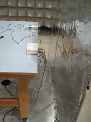
7 CONDUCTED EMISSIONS Test Setup Photos Page 7 of 21

8 Page 8 of 21
9 Test Data Sheets Test Location: CKC Laboratories rd Dr SE Bothell, WA Customer: Cadwell Industries Specification: FCC (b) Class A - AVE Work Order #: Date: 3/16/2009 Test Type: Conducted Emissions Time: 3:33:13 PM Equipment: Electroneurodiagnostic monitoring Sequence#: 6 system Manufacturer: Cadwell Tested By: Armando Del Angel Model: Easy Wireless EEG 110V 60Hz S/N: ENG001 Test Equipment: Function S/N Calibration Date Cal Due Date Asset # Agilent E4440A MY /31/ /31/2010 AN02872 Cable 30' 11 11/05/ /05/2010 ANP05366 Cable 6' 49 11/10/ /10/2010 ANP05371 Cable 20' 16 11/10/ /10/2010 ANP05360 Attenuator /21/ /21/2010 ANP05503 Filter G /21/ /21/2010 AN02611 EMCO LISN /01/ /01/2009 AN01492 Equipment Under Test (* = EUT): Function Manufacturer Model # S/N Easy Net 32ch Amp Cadwell 32 Channel EEG Easynet amp ENG1 Easy Wireless recorder Cadwell Easy Wireless s ENG001 Electroneurodiagnostic Cadwell Easy Wireless EEG ENG001 monitoring system* Easy Net Microphone Cadwell N/A N/A Power/Com Module Cadwell Easy III power/com module 0709PX Battery 3.3Vdc Cadwell AVT Support Devices: Function Manufacturer Model # S/N Test Conditions / Notes: Temp: = 23 C Rel. Humidity = 26% Atm. Pressure = 101.9kPa Testing Conducted Emissions per FCC Class A EUT's are located in the Test table. They are connected in the following order: Power/Com Module - Easy Wireless recorder (with battery) - Easy net 32ch amp - Easy net microphone The power is 230/50 VAC And the Power/Com module is also connected to a support computer in the outside of the chamber. EUT is in operational mode. Page 9 of 21
10 Transducer Legend: T1=CAB-ANP05371 T3=CAB-ANP05366 T5=CAB-ANP05360 T2=FIL-AN T4=ATT-ANP T6=CDN-AN Line Measurement Data: Reading listed by margin. Test Lead: Line # Freq Rdng T1 T2 T3 T4 Dist Corr Spec Margin Polar T5 T6 MHz dbµv db db db db Table dbµv dbµv db Ant M Line M Line M Line M Line M Line M Line M Line M Line M Line M Line M Line M Line M Line M Line M Line M Line M Line M Line M Line M Line Page 10 of 21
11 M M M M M M M M M M Line Line Line Line Line Line Line Line Line Line Page 11 of 21
12 Test Location: CKC Laboratories rd Dr SE Bothell, WA Customer: Cadwell Industries Specification: FCC (b) Class A - AVE Work Order #: Date: 3/16/2009 Test Type: Conducted Emissions Time: 3:26:34 PM Equipment: Electroneurodiagnostic monitoring Sequence#: 5 system Manufacturer: Cadwell Tested By: Armando Del Angel Model: Easy Wireless EEG 110V 60Hz S/N: ENG001 Test Equipment: Function S/N Calibration Date Cal Due Date Asset # Agilent E4440A MY /31/ /31/2010 AN02872 Cable 30' 11 11/05/ /05/2010 ANP05366 Cable 6' 49 11/10/ /10/2010 ANP05371 Cable 20' 16 11/10/ /10/2010 ANP05360 Attenuator /21/ /21/2010 ANP05503 Filter G /21/ /21/2010 AN02611 EMCO LISN /01/ /01/2009 AN01492 Equipment Under Test (* = EUT): Function Manufacturer Model # S/N Easy Net 32ch Amp Cadwell 32 Channel EEG Easynet amp ENG1 Easy Wireless recorder Cadwell Easy Wireless s ENG001 Electroneurodiagnostic Cadwell Easy Wireless EEG ENG001 monitoring system* Easy Net Microphone Cadwell N/A N/A Power/Com Module Cadwell Easy III power/com module 0709PX Battery 3.3Vdc Cadwell AVT Support Devices: Function Manufacturer Model # S/N Test Conditions / Notes: Temp: = 23 C Rel. Humidity = 26% Atm. Pressure = 101.9kPa Testing Conducted Emissions per FCC Class A EUT's are located in the Test table. They are connected in the following order: Power/Com Module - Easy Wireless recorder (with battery) - Easy net 32ch amp - Easy net microphone The power is 230/50 VAC And the Power/Com module is also connected to a support computer in the outside of the chamber. EUT is in operational mode. Page 12 of 21
13 Transducer Legend: T1=CAB-ANP05371 T3=CAB-ANP05366 T5=CAB-ANP05360 T2=FIL-AN T4=ATT-ANP T6=CDN-AN Neutral Measurement Data: Reading listed by margin. Test Lead: Neutral # Freq Rdng T1 T2 T3 T4 Dist Corr Spec Margin Polar T5 T6 MHz dbµv db db db db Table dbµv dbµv db Ant M Neutr M Neutr M Neutr M Neutr M Neutr M Neutr M Neutr M Neutr M Neutr M Neutr M Neutr M Neutr M Neutr M Neutr M Neutr M Neutr M Neutr M Neutr M Neutr M Neutr Page 13 of 21
14 M M M M M M M M M M Neutr Neutr Neutr Neutr Neutr Neutr Neutr Neutr Neutr Neutr Page 14 of 21


15 RADIATED EMISSIONS Test Setup Photos Page 15 of 21
16 Test Data Sheets Test Location: CKC Laboratories rd Dr SE Bothell, WA Customer: Cadwell Industries Specification: CLASS A Work Order #: Date: 3/16/2009 Test Type: Radiated Scan Time: 14:25:27 Equipment: Electroneurodiagnostic monitoring Sequence#: 1 system Manufacturer: Cadwell Tested By: Armando Del Angel Model: Easy Wireless EEG S/N: ENG001 Test Equipment: Function S/N Calibration Date Cal Due Date Asset # HP 8447D Preamp 2944A /08/ /08/2010 AN01517 Agilent E4440A MY /31/ /31/2010 AN02872 Cable 6' 51 12/30/ /30/2010 ANP05361 Antenna /22/ /22/2010 AN01994 Cable 30' 11 11/05/ /05/2010 ANP05366 Cable 6' 49 11/10/ /10/2010 ANP05371 Cable 20' 16 11/10/ /10/2010 ANP05360 Equipment Under Test (* = EUT): Function Manufacturer Model # S/N Easy Net 32ch Amp Cadwell 32 Channel EEG Easynet amp ENG1 Easy Wireless recorder Cadwell Easy Wireless s ENG001 Electroneurodiagnostic Cadwell Easy Wireless EEG ENG001 monitoring system* Easy Net Microphone Cadwell N/A N/A Power/Com Module Cadwell Easy III power/com module 0709PX Battery 3.3Vdc Cadwell AVT Support Devices: Function Manufacturer Model # S/N Test Conditions / Notes: Temp: = 23 C Rel. Humidity = 26% Atm. Pressure = 101.9kPa Testing Radiated Emissions per FCC A EUT's are located in the Test table. They are connected in the following order: Power/Com Module - Easy Wireless recorder (with battery) - Easy net 32ch amp - Easy net microphone The power is 230/50 VAC And the Power/Com module is also connected to a support computer in the outside of the chamber. EUT is in operational mode. Page 16 of 21
17 Transducer Legend: T1=AMP-AN T3=CAB-ANP05360 T5=CAB-ANP05366 T2=ANT AN MHz T4=CAB-ANP05361 T6=CAB-ANP05371 Measurement Data: Reading listed by margin. Test Distance: 3 Meters # Freq Rdng T1 T5 T2 T6 T3 T4 Dist Corr Spec Margin Polar MHz dbµv db db db db Table dbµv/m dbµv/m db Ant M Vert QP ^ M Vert M Vert M Vert M Vert M Vert M Vert M Vert M Vert M Vert M Vert M Vert M Vert M Vert M Vert M Vert M Vert M Vert M Vert M Vert Page 17 of 21
18 M Vert M Vert M Vert M Vert QP ^ M Vert M Vert QP ^ M Vert M Vert QP ^ M Vert M Vert QP ^ M Vert M Vert QP ^ M Vert M Vert QP M Vert QP ^ M Vert +0.9 Page 18 of 21
19 Test Location: CKC Laboratories rd Dr SE Bothell, WA Customer: Cadwell Industries Specification: CLASS A Work Order #: Date: 3/16/2009 Test Type: Radiated Scan Time: 14:44:11 Equipment: Electroneurodiagnostic monitoring Sequence#: 2 system Manufacturer: Cadwell Tested By: Armando Del Angel Model: Easy Wireless EEG S/N: ENG001 Test Equipment: Function S/N Calibration Date Cal Due Date Asset # HP 8447D Preamp 2944A /08/ /08/2010 AN01517 Agilent E4440A MY /31/ /31/2010 AN02872 Cable 6' 51 12/30/ /30/2010 ANP05361 Antenna /22/ /22/2010 AN01994 Cable 30' 11 11/05/ /05/2010 ANP05366 Cable 6' 49 11/10/ /10/2010 ANP05371 Cable 20' 16 11/10/ /10/2010 ANP05360 Equipment Under Test (* = EUT): Function Manufacturer Model # S/N Easy Net 32ch Amp Cadwell 32 Channel EEG Easynet amp ENG1 Easy Wireless recorder Cadwell Easy Wireless s ENG001 Electroneurodiagnostic Cadwell Easy Wireless EEG ENG001 monitoring system* Easy Net Microphone Cadwell N/A N/A Power/Com Module Cadwell Easy III power/com module 0709PX Battery 3.3Vdc Cadwell AVT Support Devices: Function Manufacturer Model # S/N Test Conditions / Notes: Temp: = 23 C Rel. Humidity = 26% Atm. Pressure = 101.9kPa Testing Radiated Emissions per EN Class A EUT's are located in the Test table. They are connected in the following order: Power/Com Module - Easy Wireless recorder (with battery) - Easy net 32ch amp - Easy net microphone The power is 230/50 VAC And the Power/Com module is also connected to a support computer in the outside of the chamber. EUT is in operational mode. Page 19 of 21
20 Transducer Legend: T1=AMP-AN T3=CAB-ANP05360 T5=CAB-ANP05366 T2=ANT AN MHz T4=CAB-ANP05361 T6=CAB-ANP05371 Measurement Data: Reading listed by margin. Test Distance: 3 Meters # Freq Rdng T1 T5 T2 T6 T3 T4 Dist Corr Spec Margin Polar MHz dbµv db db db db Table dbµv/m dbµv/m db Ant M Horiz M Horiz M Horiz M Horiz M Horiz QP ^ M Horiz M Horiz M Horiz M Horiz M Horiz M Horiz M Horiz M Horiz M Horiz M Horiz M Horiz M Horiz M Horiz M Horiz M Horiz +1.0 Page 20 of 21
21 M Horiz M Horiz M Horiz M Horiz M Horiz M Horiz M Horiz M Horiz QP ^ M Horiz +1.0 Page 21 of 21
Test Report #: Date: June 21, 2005
 CERTIFICATE #2316.01 Test Report #: 1979-2 Date: June 21, 2005 Issued To: Bill Burks American Power Conversion 85 Rangeway Road North Billerica, MA 01862 USA 978-670-2440 Product Name/Description Uninterruptable
Cardiocom. CD320 Commander Flex FCC :2015 FCC Report # CCOM NVLAP Lab Code:
 Cardiocom CD320 Commander Flex FCC 15.207:2015 FCC 15.249.2015 Report # CCOM0021.1 NVLAP Lab Code: 200881-0 This report must not be used to claim product certification, approval, or endorsement by NVLAP,
The above item, as tested, is considered to comply with the above specifications. PAGE 1 OF 6
 APPLICANT: Suck UK Limited 31 Regent Studios 8 Andrews Road London E8 4QN DATE: 17 th January 2014 For the attention of Emma SAMPLE DESCRIPTION: Bottlelight REFERENCE / STYLE NO.: SK LIGHTBOTTLE 1 RETAILER:
CONTENT. Report No.: GZ R6. Page 2 of 17
 CONTENT TEST REPORT... 1 CONTENT... 2 1 TEST RESULTS SUMMARY... 3 2 EMC RESULTS CONCLUSION... 4 3 LABORATORY MEASUREMENTS... 6 4 HARMONIC OF CURRENT... 7 4.1 USED TEST EQUIPMENT... 7 4.2 BLOCK DIAGRAM
Calibration Summary of Test Report No.: Sample
 Calibration Summary of Test Report No.:30043 Rion Type: NL52/EX Serial no: 00732122 Customer: Scantek, Inc. Address: 6430 Dobbin Rd., Suite C, Columbia MD, 21045 Contact Person: Mariana Buzduga Phone No.:
INSTRUCTION MANUAL. Microphone Type 4966 for Hand held Analyzer Types 2250, 2250 L and Supplement to Instruction Manual BE 1712
 INSTRUCTION MANUAL Microphone Type 4966 for Hand held Analyzer Types 2250, 2250 L and 2270 Supplement to Instruction Manual BE 1712 BE 1897 11 English Microphone Type 4966 for Hand-held Analyzer Types
Models: BRP391 series; BRP392 series; BRP394 series;
 -page 1 of 99-6011997.50 EMC Test report for LED street lighting Models: BRP391 series; BRP392 series; BRP394 series; Shanghai, date of issue: July. 09 th, 2017 Author: Jerremy Cai By order of Philips
IEC Test Report for mini-box.com Report No. NF September 29, Test Report
 Test Report Report No NF0693-1 Client mini-box.com 4031 Clipper Ct Fremont, CA 94538 Items tested WRAP-BOX-2A-1E Specifications IEC 60529 IP65 Rating Results As detailed within this report Prepared by
Advancing medical technology to help you help others.
 Advancing medical technology to help you help others. Experience The Cadwell Difference Since 1979 The benefits of owning a Cadwell system are numerous. Our development team understands and delivers what
Certification Exhibit FCC ID: R7PIWRS4. FCC Rule Part: ACS Report Number: W03.11.A
 Certification Exhibit FCC ID: R7PIWRS4 FCC Rule Part: 15.247 ACS Report Number: 09-0412.W03.11.A Manufacturer: Cellnet Technology Inc. Model: Gridstream DCIWR Manual 5015 B.U. Bowman Drive Buford, GA 30518
I/P Transducer Positioner Module
 I/P Transducer Positioner Module VRC P/N: 7958032 Installation, Operation and Maintenance Instructions 2.09 [53.1] 1.30 [32.9] 2.97 [75.5] 0.78 [19.8] 0.18 [4.4] 1.42 [36.1] n.18 MOUNTING HOLES (2) PLACES
Engineering Report Crash Safety (Impulse) Shock Test. Crystal Group, Inc. for. Prepared by. Phillip M. Toftely, Test Engineer.
 Shock Test. Crystal Group, Inc. for. Prepared by. Phillip M. Toftely, Test Engineer.") Engineering Report 47706-2 Crash Safety (Impulse) Shock Test for Crystal Group, Inc. Prepared by Phillip M. Toftely, Test Engineer Approved by David M. Gillen, Vice President This document shall not be
Engineering Report 47706-2 Crash Safety (Impulse) Shock Test for Crystal Group, Inc. Prepared by Phillip M. Toftely, Test Engineer Approved by David M. Gillen, Vice President This document shall not be
PROGRAMMER OPERATIONS MANUAL
 PROGRAMMER OPERATIONS MANUAL Table of Contents Description 4 Installation 4 Operation 5 Safety Precautions 5 Regulatory & Service Information 6 Important Safety and Usage Information 7 Regulatory Notices
CS115 BAROMETRIC PRESSURE SENSOR INSTRUCTION MANUAL
 CS115 BAROMETRIC PRESSURE SENSOR INSTRUCTION MANUAL 3/03 COPYRIGHT (c) 2002-2003 CAMPBELL SCIENTIFIC, INC. This is a blank page. WARRANTY AND ASSISTANCE This equipment is warranted by CAMPBELL SCIENTIFIC
SHENZHEN LCS COMPLIANCE TESTING LABORATORY LTD. FCC ID: ZSH-Y50Y55 Report No.: LCS AED. Appendix C
 Appendix C RF Test Data for 2.4G WIFI (Conducted Measurement) Product Name: 4G Smartphones Trade Mark: Kenxinda, Ken mobile, KXD, E&L, EL Test Model: Y50 Environmental Conditions Temperature: 24.6 C Relative
Qualification of Fastrak & First Gen Product to Railway applications Shock and Vibration Standard EN 61373
 Qualification of Fastrak & First Gen Product to Railway applications Shock and Vibration Standard EN 61373 (Governing Standard BS EN 5155 Railway Applications Electronic equipment used on rolling stock)
Wireless Belt Pack BP Conductor with Radio Transmit
 Wireless Belt Pack BP5-10 5-Conductor with Radio Transmit Operation Manual 7340 SW Durham Road Portland, OR 97224 USA Phone: 503-684-6647 1-800-527-0555 Fax: 503-620-2943 email: sales@firecom.com www.firecom.com
Wireless Belt Pack BP Conductor Jack with Radio Transmit & Volume Control
 Wireless Belt Pack BP3-10 3-Conductor Jack with Radio Transmit & Volume Control Operation Manual 7340 SW Durham Road Portland, OR 97224 USA Phone: 503-684-6647 1-800-527-0555 Fax: 503-620-2943 email: sales@firecom.com
Test Report Number: CRT-026 Project Number:
 3933 US Route 11 Cortland, NY 1345 Telephone: (67) 753-6711 Facsimile: (67) 758-3659 www.intertek.com November 1, 217 Test Report Number: 1246639CRT-26 Project Number: 1246639 Legrand North America Superior
ANSI/TIA-568-C-2009: Balanced Twisted-Pair Telecommunications Cabling and Components Standard, dated August 2009
 3933 US Route 11 Cortland, NY 1345 Telephone: (67) 753-6711 Facsimile: (67) 758-3659 www.intertek.com November 1, 217 Test Report Number: 1246639CRT-27 Project Number: 1246639 TEST: Legrand North America
Proof of Performance - Summary System Operator: BVU Authority
 Proof of Performance - Summary System Operator: BVU Authority Date: 07-Jul-2016 System Name: BVU Authority State: Virginia System Address: 15022 Lee Highway ZIP: 24202 Integrated Hubs: 0 Subscriber Count:
CTAG:b9927e36a4b3f34a9138ce0bb2426b22 Certificate of Calibration
 CTAG:b997e6abfa98cebb6b Certificate of Calibration Data Type: FOUND-LEFT Certificate No: 79 Instrument Description Manufacturer Model Serial Number Inventory Number CABLE ANALYZER FLUKE NETWORKS DTX-8
APPENDIX A
 APPENDIX A APPENDIX B Staff GIS Empey Hill Area West Legend 0 800 1600 2400 m. This map is a user generated static output from an Internet mapping site and is for general reference only.
Agilent 7800 ICP-MS. Specifications and Typical Performance. Fast track metals analysis with Solution-Ready ICP-MS
 Agilent 7800 ICP-MS Specifications and Typical Performance Fast track metals analysis with Solution-Ready ICP-MS The Solution-Ready Agilent 7800 Quadrupole ICP-MS combines proven, robust hardware, auto-optimization
PPC4E Pressure Controller/Calibrator Superior rangeability and reliability
 PPC4E Pressure Controller/Calibrator Superior rangeability and reliability Technical Data ± 0.02 % of AutoRanged spans from ± 1 kpa (0.15 psi) to 14 MPa (2,000 psi) The Fluke Calibration PPC4E brings high
DD2 Site Preparation Checklist Hardware Site Preparation Specification
 Thank you for purchasing an Agilent instrument. To get you started and to assure a successful and timely installation, please refer to this specification or set of requirements. Correct site preparation
PTB Ex PT Scheme. Procedure Instruction of program Explosion Pressure - Test Round 2017
 Procedure Instruction of program Explosion Pressure - Test Round 2017 Content 1 General Performance... 2 2 Measurand / Characteristic of interest... 2 3 Test Item and Configurations... 2 3.1 Components...
ANSI/TIA-568-C : Balanced Twisted-Pair Telecommunications Cabling and Components Standard, dated August 2009
 3933 US Route 11 Cortland, NY 1345 Telephone: (67) 753-6711 Facsimile: (67) 758-3659 www.intertek.com April 4, 213 Test Report Number: 33592CRT-99 Project Number: 33592 Legrand North America 125 Eugene
CTAG:e43bda4f8e48714fbb aefb192 Certificate of Calibration
 CTAG:ebdaf8e87fbb5996aefb9 Certificate of Calibration Data Type: FOUND-LEFT Certificate No: 6858 Instrument Description Manufacturer Model Serial Number Inventory Number CABLE ANALYZER FLUKE NETWORKS DTX-8
MEDIA 2 OPERATIONS MANUAL
 MEDIA 2 OPERATIONS MANUAL Table of Contents Introduction Introduction............................................................... 3 Rear Panel Overview.......................................................
Vaisala Pressure, RH & Temp. Transmitter. The instrument was operational upon receipt. The instrument was adjusted and calibrated.
 Asset #: 123 Calibration - Certificate No: 2083.01 Customer: Condition: Action Taken: Sample Inc. 123 Sample Rd. Sample, MA 01234 The instrument was operational upon receipt. The instrument was adjusted
_ pressure transducers. User Manual
 _ pressure transducers User Manual summary introduction DescriPTION preliminary checks Installation taking measurements data management Troubleshooting maintenance Appendix 1 Page 4 Page 5 Page 6 Page
SAR COMPLIANCE REPORT
 Stanley Black & Decker, Inc. SAR COMPLIANCE REPORT Report Type: FCC SAR assessment report Model: MHL600 REPORT NUMBER: 180501586SHA-002 ISSUE DATE: Aug 30, 2018 DOCUMENT CONTROL NUMBER: TTRFFCCSAR-01_V1
Test Report Number: CRT-095 Project Number:
 3933 US Route 11 Cortland, NY 1345 Telephone: (67) 753-6711 Facsimile: (67) 758-3659 www.intertek.com April 17, 213 Test Report Number: 33592CRT-95 Project Number: 33592 Legrand North America 125 Eugene
Setting up and carrying out a check source measurement
 Setting up and carrying out a check source measurement 1 Introduction Ionisation chambers are relatively fragile devices and can be faulty with little or no visible sign of damage. Because of this, most
Alphasense Application Note AAN NDIR: Gas Concentration Calculation Overview
 AAN 21-6 NDIR: Gas Concentration Calculation Overview 1. What is an NDIR Sensor? Alphasense IRC-A sensors use the principle of Non-Dispersive Infra-Red (NDIR to determine gas concentration. Each sensor
Parametrable / Programmable Pressure Transmitter
 Parametrable / Programmable Pressure Transmitter PTM/RS485 CUSTOMER BENEFITS High flexibility due to scalalbe pressure range Digital (RS485) and analogue (4-20mA) output signal in one sensor Available
Programmable Submersible Level Transmitters
 Programmable Submersible Level Transmitters PTM/N/RS485 CUSTOMER BENEFITS High flexibility due to scalalbe pressure range Digital (RS485) and analogue (4-20mA) output signal in one sensor Available as
P9000 DESCRIPTION. For parts requiring RoHS compliance, please contact factory. P February /6
 P9000 High accuracy through digital compensation High thermal stability Rugged stainless steel construction Ideal for test stands High burst pressure limit DESCRIPTION The P9000 Series is a range of advanced,
Pneumatic high-pressure controller Model CPC7000
 Calibration technology Pneumatic high-pressure controller Model CPC7000 WIKA data sheet CT 27.63 Applications Healthcare and avionics industry Industry (laboratory, workshop and production) Transmitter
tr-- CALIBRATION CERTIFICATE Calibration Laboratory of Schmid & Partner Engineering AG Zeughausstrasse 43, 8004 Zurich, Switzerland DSGHzV2 - SN:1006
 Calibration Laboratory of Schmid & Partner Engineering AG Zeughausstrasse 43, 8004 Zurich, Switzerland s Schweizerischer Kalibrierdienst C Service suisse d'etalonnage Servizio svizzero di taratura S Swiss
Pneumatic high-pressure controller Model CPC7000
 Calibration technology Pneumatic high-pressure controller Model CPC7000 WIKA data sheet CT 27.63 Applications Automotive and avionics industry Industry (laboratory, workshop and production) Transmitter
SDX Submersible Depth Transmitter User Manual
 SDX Submersible Depth Transmitter User Manual July 2017 USER INFORMATION Stevens makes no warranty as to the information furnished in these instructions and the reader assumes all risk in the use thereof.
MOTOROLA PTP 800 LICENSED ETHERNET MICROWAVE
 HIGH-THROUGHPUT COMMUNICATIONS FOR MULTI-SERVICE NETWORKS MOTOROLA PTP 800 LICENSED ETHERNET MICROWAVE PTP 800 solutions can efficiently and affordably transport the data, voice and video that your bandwidth-intensive
SDX Submersible Depth Transmitter User Manual
 SDX Submersible Depth Transmitter User Manual October 2007 USER INFORMATION Stevens makes no warranty as to the information furnished in these instructions and the reader assumes all risk in the use thereof.
Genesis MX SLM-Series
 Single Frequency Visible OEM and End-User OPS Laser Systems Applications like Flow Cytometry, Particle Counting, DNA Sequencing and Microscopy are enable by low noise, visible true CW lasers. The Genesis
Rigel 601 CHECKBOX. Instruction Manual. 348A551 Issue 2.0. April Seaward Electronic Ltd. Issue 2.0
 Rigel 601 CHECKBOX Instruction Manual 348A551 Issue 2.0 April 2006 2006 Seaward Electronic Ltd. Issue 2.0 Limited Warranty & Limitation of Liability Rigel Medical guarantees this product for a period of
Real-time Analysis of Industrial Gases with Online Near- Infrared Spectroscopy
 Real-time Analysis of Industrial Gases with Online Near- Infrared Branch 5 Petrochemical, Biofuels Keywords Process, NIR, Gases, Gas Cell, Ethylene, Carbon Dioxide, Propane, Butane, Acetylene Summary Near-infrared
GMA FUNCTIONAL TEST SETTING & TESTING OF SPIN UP PARAMETERS. P0586 REV -- 20, June 2000 GPB SCIENCE MISSION PROCEDURE
 P0586 Rev. June 20, 2000 STANFORD UNIVERSITY W.W. HANSEN EXPERIMENTAL PHYSICS LABORATORY GRAVITY PROBE B, RELATIVITY GYROSCOPE EXPERIMENT STANFORD, CALIFORNIA 94305-4085 GMA FUNCTIONAL TEST SETTING & TESTING
DESIGN VERIFICATION AND QUALIFICATION OF NEW POPPET AND BUSHING ON GMA FLIGHT SOLENOID VALVES
 STANFORD UNIVERSITY W.W. HANSEN EXPERIMENTAL PHYSICS LABORATORY GRAVITY PROBE B, RELATIVITY GYROSCOPE EXPERIMENT STANFORD, CALIFORNIA 94305-4085 DESIGN VERIFICATION AND QUALIFICATION OF NEW POPPET AND
Programmable pressure and temperature transmitters PTM/RS485
 Programmable pressure and temperature transmitters PTM/RS485 Version: 26.06.2014 Technical Specifications Pressure measuring range (bar) 0.1... 0.5 > 0.5 2 > 2 25 Overpressure 3 bar 3 x FS ( 3 bar) 3 x
Sensor for Air Bubble Detection at Liquid Filled Tubes. SONOCHECK Type ABD06.xx. Operating Manual
 Sensor for Air Bubble Detection at Liquid Filled Tubes SONOCHECK Type ABD06.xx Operating Manual Manufacturer: Model: Type: SONOTEC Ultraschallsensorik Halle GmbH Air Bubble Detector ABD06.xx SONOTEC Ultraschallsensorik
GasSense NDIR User Manual
 INDEX INDEX... 1 1. OVERVIEW... 2 2. TECHNICAL DATA... 3 3. SPECIFICATIONS... 4 4. PRODUCT DESCRIPTION... 5 4.1 Mechanical details... 5 4.2 Piping... 7 4.3 Connections... 7 5. INSTALLATION... 10 6. CALIBRATION
Victoreen B. Operators Manual. Image Intensifier Ion Chamber
 Victoreen 6000-530B Image Intensifier Ion Chamber Operators Manual March 2005 Manual No 6000-530B-1 Rev. 4 2004, 2005 Fluke Corporation, All rights reserved. All product names are trademarks of their respective
Wi-Fi 2.4 GHz. 0 db = 1.91 W/kg = 2.81 dbw/kg
 Test Laboratory: UL Verification Services Inc. SAR Lab B Date/Time: 12/8/2016 5:52:38 PM Wi-Fi 2.4 GHz Frequency: 2462 MHz; Duty Cycle: 1:1; Room Ambient Temperature: 24.0 C; Liquid Temperature: 23.0 C
SPIRIT III Radiometer Saturation Effect
 Utah State University DigitalCommons@USU Space Dynamics Lab Publications Space Dynamics Lab 1-1-1997 SPIRIT III Radiometer Saturation Effect Joseph J. Tansock Follow this and additional works at: https://digitalcommons.usu.edu/sdl_pubs
REMOTE MICROPHONE 2 OPERATIONS MANUAL
 REMOTE MICROPHONE 2 OPERATIONS MANUAL Table of Contents Introduction 4 Basic Use 6 Controls Overview 8 Low Battery and Charging 10 Power On/Off Slider 12 Syncing to Hearing Instruments 13 Built-In Microphones
Final Report: Measurements of Pile Driving Noise from Control Piles and Noise-Reduced Piles at the Vashon Island Ferry Dock
 Final Report: Measurements of Pile Driving Noise from Control Piles and Noise-Reduced Piles at the Vashon Island Ferry Dock By Peter H. Dahl, Jim Laughlin, and David R. Dall Osto Executive Summary Underwater
Programmable pressure and temperature transmitters PTM/RS485
 Programmable pressure and temperature transmitters PTM/RS485 Version: 03-28-2012 Technical Specifications Pressure measuring range (bar) 0.1... 0.5 > 0.5 2 > 2 25 Overpressure 3 bar 3 x FS ( 3 bar) 3 x
Model SM/PL Series. Calibration Guide. Precision Loads. Anritsu Company 490 Jarvis Drive Morgan Hill, CA USA
 Calibration Guide Model SM/PL Series Precision Loads Anritsu Company 490 Jarvis Drive Morgan Hill, CA 95037-2809 USA Part Number: 10100-00056 Revision: B Published: January 2010 Copyright 2009-2010 Anritsu
Customer Responsibilities
 Thank you for purchasing an Agilent instrument. To get you started and to assure a successful and timely installation, please refer to this specification or set of requirements. Correct site preparation
Columbus Instruments
 0215-003M Portable O 2 /CO 2 /CH 4 Meter User s Manual Columbus Instruments 950 NORTH HAGUE AVENUE TEL:(614) 276-0861 COLUMBUS, OHIO 43204, USA FAX:(614) 276-0529 1 www.colinst.com TOLL FREE 1-800-669-5011
CALIBRATION CERTIFICATE # 500
 CALIBRATION CERTIFICATE # 5 Calibration date : -- Certificate issued : --8 Company name Company address City, Province, Canada CLAS 9- Calibration of Mass flow meter Brooks SLA585S S/N : ABCD QUALITY PROGRAM
UNIVERSAL MASK TEST SYSTEM
 f UNIVERSAL MASK TEST SYSTEM Quotation #110811 Automated Motion Inc. 225 NW Victoria Drive Lee s Summit, Missouri 64086-4709 www.automatedmotion.com SYSTEM OVERVIEW AMI s Universal Mask Test System is
ETd 04. Battery Powered Precision Digital Gauge. Stainless Steel Sensor. Type: ETd 04. class 0.05
 Battery Powered Stainless Steel Sensor class 0.05 Nominal pressure from 0 100 mbar up to 0... 400 bar Special characteristics modular sensor concept data logger graphic display stainless steel housing
Customer Responsibilities. Important Customer Information Series Q-TOF LC/MS Systems Site Preparation Checklist
 Thank you for purchasing an Agilent system. To get you started and to assure a successful and timely installation, please refer to this specification or set of requirements. Correct site preparation is
The HumiPyc ( Model 2) - Gas Pycnometer; Density, Moisture, Permeation Analyzer; Filter Integrity Tester; RH sensor Calibrator
 - Gas Pycnometer; Density, Moisture, Permeation Analyzer; Filter Integrity Tester; RH sensor Calibrator") The HumiPyc ( Model 2) - Gas Pycnometer; Density, Moisture, Permeation Analyzer; Filter Integrity Tester; RH sensor Calibrator Designed, built, and supported by InstruQuest Inc. Universal pycnometer, no
The HumiPyc ( Model 2) - Gas Pycnometer; Density, Moisture, Permeation Analyzer; Filter Integrity Tester; RH sensor Calibrator Designed, built, and supported by InstruQuest Inc. Universal pycnometer, no
POROUS PLUG CHARACTERIZATION TEST
 Page 1 of 28 GRAVITY PROBE B PROCEDURE FOR PAYLOAD VERIFICATION POROUS PLUG CHARACTERIZATION TEST Prepared by: Rose LaLanne PROCEDURE NO. P0537 REV. - 05/28/99 Approvals Program Responsibility Signature
ITTC Recommended Procedures and Guidelines
 Page 1 of 6 Table of Contents 1. PURPOSE...2 2. PARAMETERS...2 2.1 General Considerations...2 3 DESCRIPTION OF PROCEDURE...2 3.1 Model Design and Construction...2 3.2 Measurements...3 3.5 Execution of
UltraLo 1800 Alpha Particle Counter
 XIA LLC UltraLo 1800 Alpha Particle Counter Site Requirements & Planning Version: 0.4 Friday, February 15, 2013 Table of Contents I. Site Preparation Tasks... 3 A. Instrument Overview... 3 B. Installation
High-speed pressure sensor Model CPT6140
 Calibration technology High-speed pressure sensor Model CPT6140 WIKA data sheet CT 25.11 Applications Testing technology Calibration technology Laboratories and maintenance shops Leak and burst applications
INSTRUCTION MANUAL. FLOW CONTROL DRAWERS MANUAL / PLC CONTROL SERIES Model Version Perma Pure LLC Tel:
 PERMA PURE INSTRUCTION MANUAL FLOW CONTROL DRAWERS MANUAL / PLC CONTROL SERIES Model 3300 Version 4.06 Perma Pure LLC Tel: 732-244-0010 P.O. Box 2105, 8 Executive Drive Tel: 800-337-3762 (toll free US)
IEP SENSOR BRACKET CHECKOUT AND VERIFICATION. This is a non-hazardous test.
 Page 1 of 20 NEXT GENERATION GAS SYSTEM (NGGS ) IEP SENSOR BRACKET CHECKOUT AND VERIFICATION PROCEDURE 870-PROC-623 Revision A Goddard Space Flight Center Greenbelt, Maryland 20771 FEBRUARY 13, 2002 This
All Purpose AP-Series Operation Manual
 All Purpose AP-Series Operation Manual CARDINAL SCALE MFG. CO. 8525-M176-O1 Rev J 203 E. Daugherty, Webb City, MO 64870 USA Printed in USA 10/00 Ph: 417-673-4631 Fax: 417-673-2153 www.detectoscale.com
DCS Series 1 kw, 1.2 kw, & 3 kw
 Established 1981 Advanced Test Equipment Rentals www.atecp.com 800-404-ATEC (2832) DCS Series 1 kw, 1.2 kw, & 3 kw DCS Applications The DCS Family is ideally suited f a wide range of applications requiring
UNDERSTANDING, ACCELERATED
 UNDERSTANDING, ACCELERATED MEASURE FLOW, PRESSURE, AND TEMPERATURE ALL IN ONE INSTRUMENT! Designed for Performance TSI thermal mass flowmeters incorporate a proprietary platinum film sensor design for
CMA4000 Specifications
 CMA4000 Specifications Display Mass Storage VGA LCD Display (8.4 color or 8.2 monochrome) Up to 125 traces internal storage. Over 65,000 traces with optional hard drive. Up to 180 traces for a standard
Oldman 2 Wind Farm Limited
 Decision 22676-D01-2017 Spring 2017 Post-Construction Sound Survey at Receptors B, J and K August 1, 2017 Alberta Utilities Commission Decision 22676-D01-2017 Proceeding 22676 Application 22676-A001 August
PTP 800 SPLIT-MOUNT SOLUTION
 TM PTP 800 SPLIT-MOUNT SOLUTION LICENSED ETHERNET MICROWAVE FOR MULTI-SERVICE NETWORKS Cambium Point-to-Point (PTP) 800 Licensed Ethernet Microwave Solutions can efficiently and affordably transport the
Perpetua Power Puck Solutions
 Perpetua Power Puck Solutions Product Data Sheet October 2015 00813-0100-4404, Rev AA Continuous, long-life power for wireless transmitters High transmitter update rates without battery life impact Intrinsically
Differenz-Drucktransmitter Differential pressure transmitter Transmetteur de pression différentielle bar
 692 Differenz-Drucktransmitter Differential pressure transmitter Transmetteur de pression différentielle 0 0.1 25 bar E Technical overview The differential pressure transmitter of type series 692 with
SonoMeter 30 Energy Meters
 Data Sheet SonoMeter 30 Energy Meters Description The Danfoss SonoMeter 30 is a range of ultrasonic, compact energy meters intended for measuring energy consumption in heating and cooling applications
Overview. Front Panel: Keypad and Display
 Overview The GA-200B is an analyzer that integrates a gas sampling system with sensors to measure and display the concentrations of oxygen and carbon dioxide in a sample as the percentage of a gas in the
Tutorial for the. Total Vertical Uncertainty Analysis Tool in NaviModel3
 Tutorial for the Total Vertical Uncertainty Analysis Tool in NaviModel3 May, 2011 1. Introduction The Total Vertical Uncertainty Analysis Tool in NaviModel3 has been designed to facilitate a determination
Explosive Fittings Testing
 Explosive Fittings Testing BFM Global Ltd. May 2012 EXCELLENCE IS A MINIMUM REQUIREMENT Contents 1. Summary... 3 2. Description of Samples... 4 3. Equipment... 4 4. Test Plan and Methodology... 5 4.1.
User manual. PG89 Rev 01 Editi Pressotherapy model. LymphoPress 4
 User manual PG89 Rev 01 Editi 040515 Pressotherapy model LymphoPress 4 I.A.C.E.R. Srl Via S. Pertini 24/A 30030 Martellago (VE) ITALY Tel. 041.5401356 Fax 041.5402684 e-mail: iacer@iacer.it http://www.itechmedicaldivision.com
MEDIA 2 OPERATIONS MANUAL
 MEDIA 2 OPERATIONS MANUAL Table of Contents Introduction Introduction............................................................... 3 Rear Panel Overview.......................................................
Calibration Procedure
 Management Procedure 2565 Revision: A Date Issued: October 30, 2017 Date Revised: Calibration Procedure DeFelsko Corporation PosiTector RTR-3D Replica Tape Reader Probe Table of Contents 1 Introduction
DM01. Battery Powered Precision Digital Gauge. Stainless Steel Sensor. class 0.05
 Battery Powered Stainless Steel Sensor class 0.05 Nominal pressure from 0 00 mbar up to 0... 00 bar Special characteristics modular sensor concept data logger graphic display stainless steel housing Ø
Electronic gas volume corrector model DGVC-04
 Electronic gas volume corrector model DGVC-04 1. Introduction The following user s manual gives information about the installation, configuration, usage and storage of the electronic gas volume corrector
THE PRESSURE SIGNAL CALIBRATION TECHNOLOGY OF THE COMPREHENSIVE TEST
 THE PRESSURE SIGNAL CALIBRATION TECHNOLOGY OF THE COMPREHENSIVE TEST SYSTEM Yixiong Xu Mechatronic Engineering, Shanghai University of Engineering Science, Shanghai, China ABSTRACT The pressure signal
TSE Blood Pressure Monitor Invasive series
 TSE Blood Pressure Monitor Invasive 209100series For Invasive Measurements in Laboratory Animals 2 Specifications subject to change without notice USA / Canada / Mexico Phone 1-989-698-3067 Fax 1-989-698-3068
AUK Environmental Sensor. Determining the refractive index of the air. AUK Environmental Sensor
 AUK Environmental Sensor Environmental influences can be compensated in two ways: 1. "Manual" input of the current data for air temperature, humidity and pressure and the material temperature of the testpiece
Measuring range Δp (span = 100%) Pa
 Pa") 4.4/ RLE 5: Volume-flow controller, continuous How energy efficiency is improved Enables demand-led volume flow control for the optimisation of energy consumption in ventilation systems. Areas of application
4.4/ RLE 5: Volume-flow controller, continuous How energy efficiency is improved Enables demand-led volume flow control for the optimisation of energy consumption in ventilation systems. Areas of application
REMOTE CONTROL OPERATIONS MANUAL
 REMOTE CONTROL OPERATIONS MANUAL BASIC MODEL ADVANCED MODEL 1 1 2 2 7 3 3 8 4 6 4 5 5 2 SurfLink Remote allows for easy and discreet adjustments to your hearing instruments. With its long-life battery,
REMOTE CONTROL OPERATIONS MANUAL
 REMOTE CONTROL OPERATIONS MANUAL BASIC MODEL 1 2 3 4 5 SurfLink Remote allows for easy and discreet adjustments to your hearing instruments. With its long-life battery, your SurfLink Remote is always on
Blood Parameter Monitoring System 550
 Technical Compendium CDI Blood Parameter Monitoring System 550 An overview of the CDI System 550 and its industry leading technology. CDI System 550 Measures or Calculates 12 Critical Blood Parameters
DM01. Please visit our website: Battery Powered Precision Digital Gauge. Stainless Steel Sensor. class 0.05
 DM0 Battery Powered Stainless Steel Sensor class 0.05 Nominal pressure from 0 00 mbar up to 0... 00 bar Special characteristics modular sensor concept data logger graphic display stainless steel housing
IDL01. Battery Powered Precision Digital Gauge for Leak Testing. Stainless Steel Sensor. class 0.05
 IDL0 Battery Powered Precision Digital Gauge for Leak Testing Stainless Steel Sensor class 0.05 Nominal pressure from 0 00 mbar up to 0... 00 bar Special characteristics modular sensor concept data logger
Safety Manual. Process pressure transmitter IPT-1* 4 20 ma/hart. Process pressure transmitter IPT-1*
 Safety Manual Process pressure transmitter IPT-1* 4 20 ma/hart Process pressure transmitter IPT-1* Contents Contents 1 Functional safety 1.1 General information... 3 1.2 Planning... 4 1.3 Instrument parameter