Shell & Tube. JATCO Inc. Operating Manual
|
|
|
- Roland Blake
- 5 years ago
- Views:
Transcription
1 Shell & Tube JATCO Inc. Operating Manual 1
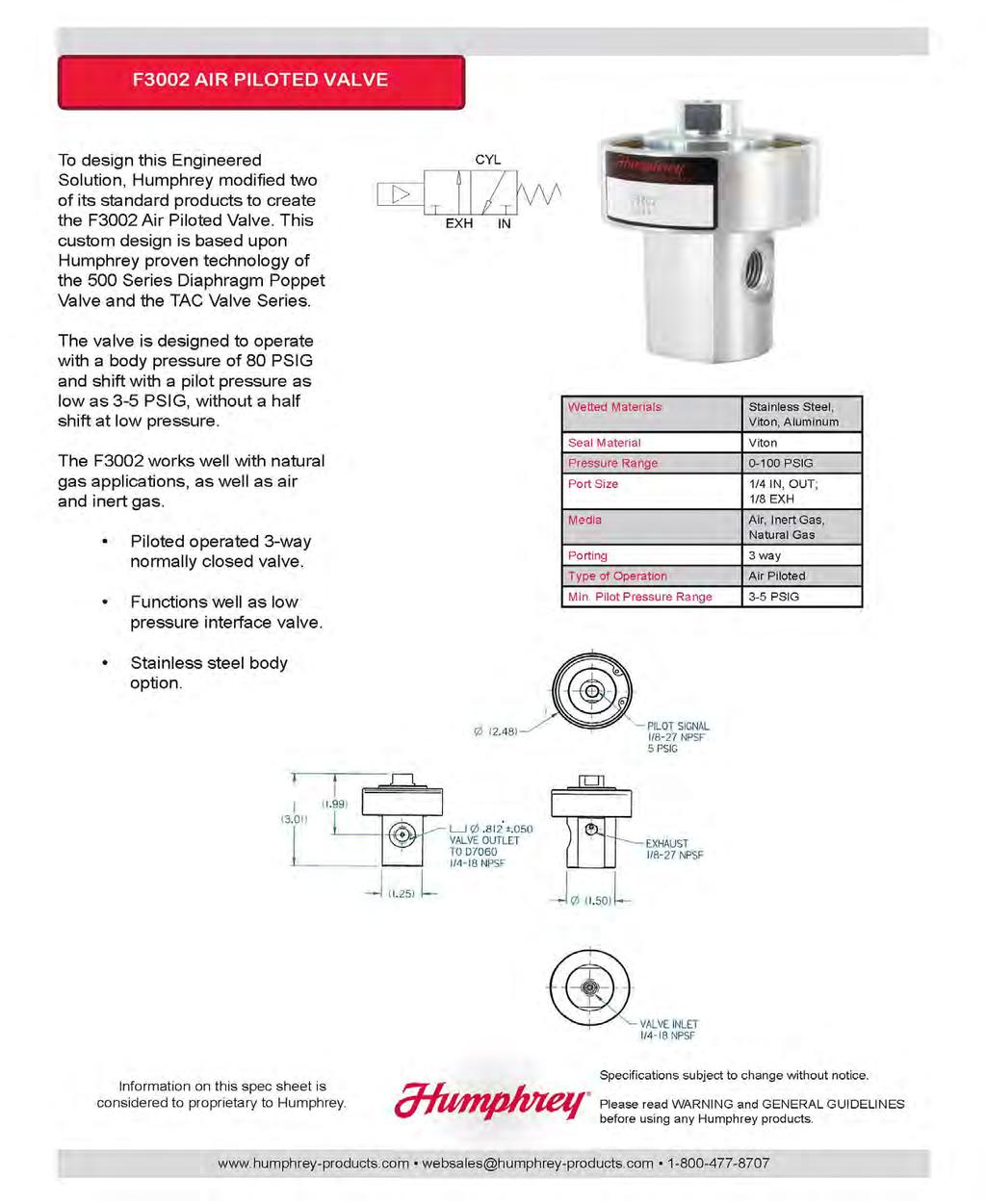
2 System Operation Operating Instructions System P&ID System Drawing Starting Procedure Shutting Down Service & Maintenance Trouble Shooting Guide Recommended Spare Parts JATCO Tank Service Spec Sheet Manual Reset Valve Actuated 3-Way Ball Valve F3002 Humphrey INDEX Page 3 Page 4 Page 5-7 Page 8-14 Page 15 Page 16 Page 17 Page 18 Page 19 Page Page 23 Page 24 & 25 Page Page 40 1/4" Humphrey Valve Page 41 JATCO Low Pressure 2" Liquid Separator High Liquid Level Shut Down Spud-In Adapter Compound Injector Burner Deflagration Flame Arrestor Micro Valve Vapor Relief Glycol Relief Warranty Page 42 Page 43 Page 44 Page 45 Page 46 & 47 Page Page 51 Page 52 & 53 Page 54 Disclaimer Page N.W. 111 th St. Oklahoma City, Oklahoma / / Fax 2
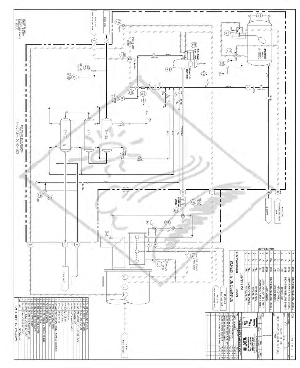
3 SHELL & TUBE SYSTEM OPERATION The JATCO BTEX ELIMINATOR is designed to condense the emissions from the still column of glycol dehydrators. The hot vapors are routed through the heat exchanger, reducing the temperature and volume of the steam and hydrocarbons produced by the dehydration process. The liquids condensed are routed by gravity into a small tank placed at the base of the condenser. The tank dumps these liquids automatically, and must be connected to a holding tank. The vapors remaining uncondensed are routed through a separation and filtering media, then to either the main burner of the dehydrator, or to the exhaust stack. All V.O.C. s are either condensed into liquids which may be separated and sold, or are burned. 244 N.W. 111 th St. Oklahoma City, Oklahoma / / Fax 3
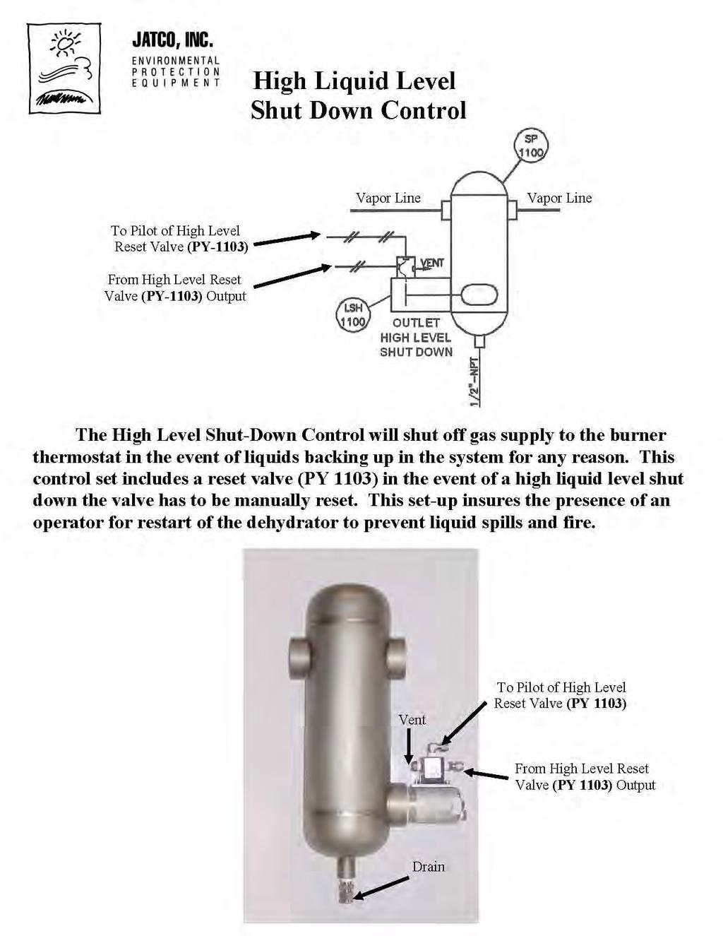
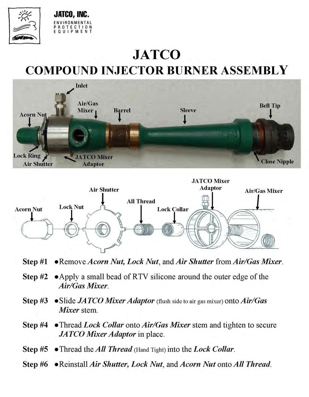
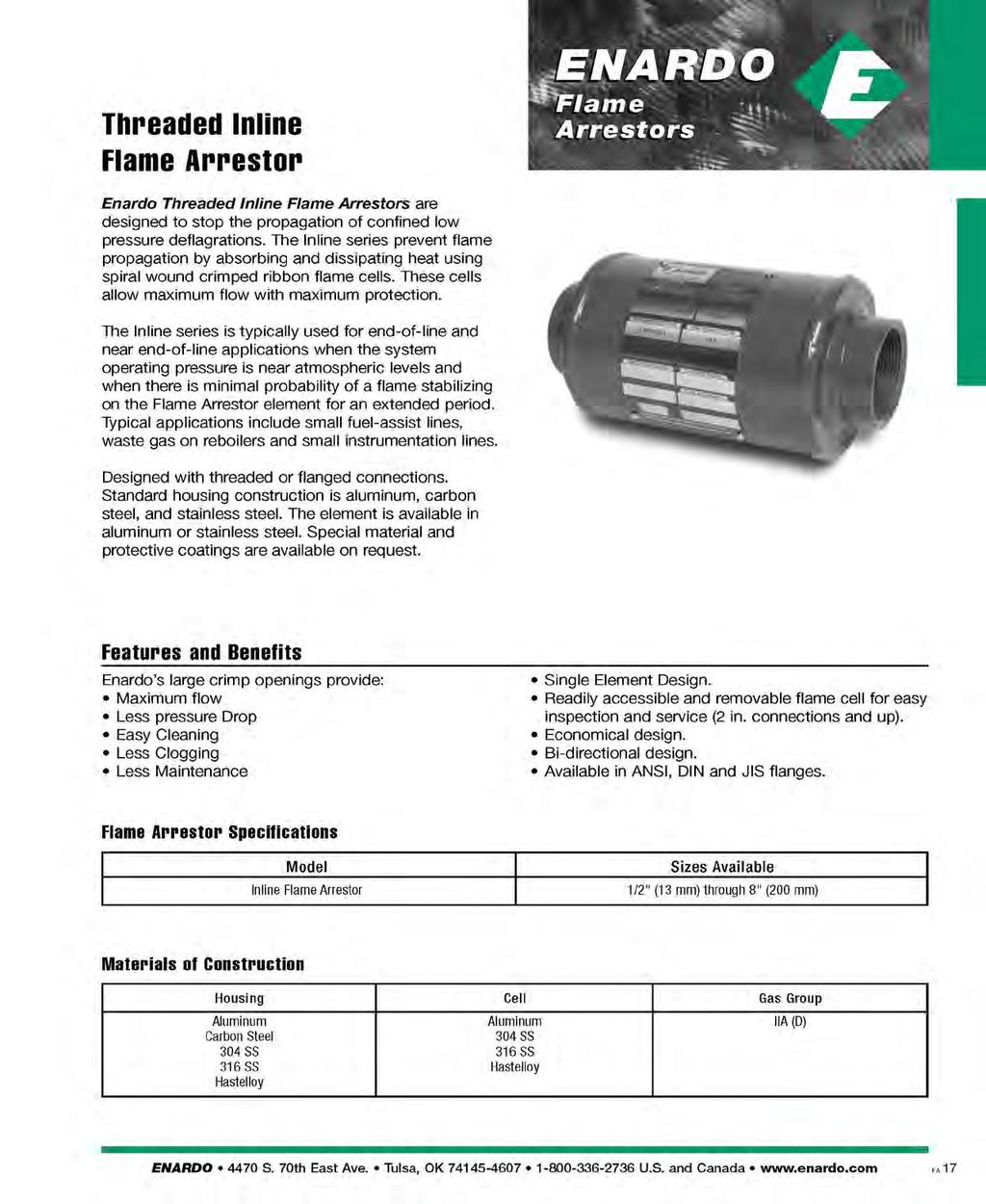
4 Shell & Tube Operating Instructions JATCO BTEX ELIMINATOR Systems See P&ID: The V.O.C. s are routed from the condenser through an actuated 3-Way ball valve then manual valve (BA-001), and the gas liquid separator (SP-1100). Then though a filtering and separating medium (ME-1101), the flame arrestor (FA-1101), then either to the burner or to the exhaust stack through a second actuated 3-way ball valve. The actuated 3-way ball valve (ABV-1100) is controlled by a relay valve (PY-1101) that receives its pilot signal from the output of the main burner fuel supply valve (SDV-Main Fuel Gas Supply) this is controlled by the temperature controller (TC). During normal operation, when the thermostat (TSH) supplies pressure to operate the burner supply valve (SDV-Main Fuel Gas Supply), the main burner fuel pressure also gives positive signal to the pilot side of (PY-1101) to allow supply gas to actuate the 3-way ball valve. When actuated the condenser residual vapors are routed to main burner. A JATCO air mixer adaptor allows the drift of fuel gas to mix the vapor with primary air in the main burner. When the set temperature of the glycol in the re-boiler is reached, the thermostat removes pressure from the valve, allowing the waste vapors to be diverted into the exhaust stack, where they are mixed with hot air being drafted into the fire tube and stack and ignited. An over temperature controller (TSH) supplies pressure to the thermostat (TC) to operate the control valves. This pressure is also used to operate an actuated 3-way ball valve (ABV-1200) mounted on the heat exchanger. This valve (ABV-1200) allows the vapors to be vented to the atmosphere during start up and automatic shutdown. It will open automatically in the event the over temperature control (TC) or the high level shut down (LSH-1000) is tripped. 244 N.W. 111 th St. Oklahoma City, Oklahoma / / Fax 4
5 5
6 6
7 7
8 8
9 9
10 10
11 11
12 12
13 13
14 14
15 SHELL & TUBE STARTING PROCEDURE See P&ID: The glycol pump should be stopped before beginning the starting sequence. All gas and waste vapors must be allowed to clear from the fire tube and exhaust stack before lighting the pilot. When lighting the pilot, the system should be bypassed by closing valves (BB-001) and (BA-001). Set the thermostat (TC) to desired glycol temperature. When the glycol reaches temperature, start the glycol pump and begin circulation through the contactor and re-boiler tank. The BTEX ELIMINATOR is designed to handle the vapors generated under normal conditions. If the glycol is saturated with water, it will be necessary to allow the excess water to dissipate before opening valves (BA-001) and (BB-001). 244 N.W. 111 th St. Oklahoma City, Oklahoma / / Fax 15
16 SHELL & TUBE SHUTTING DOWN SEE P&ID: The BTEX ELIMINATOR may be isolated from the burner and exhaust stack at any time by closing valves (BB-001) and (BA-001). This allows the vapors to vent through the Actuated 3-way ball valve. The dehydrator may then be serviced or operated normally. NORMAL OPERATION: It is important to keep the glycol flow to the minimum necessary to achieve the desired dew point of the gas stream. Any excess in flow rate will cause additional hydrocarbons to be absorbed by the glycol in the contactor. These hydrocarbons must then be condensed or burned. If a two or three phase separator is used in the wet glycol stream, the load on the condenser is greatly reduced. If no separator is used, any excess glycol flow rate may cause an over rich fuel mixture, smoking or flames from the exhaust stack. 244 N.W. 111 th St. Oklahoma City, Oklahoma / / Fax 16
17 SHELL & TUBE SERVICE AND MAINTENANCE SEE P&ID: The JATCO BTEX ELIMINATOR system has very few moving parts. Maintenance of the JATCO tank is covered in the service instructions. A pressure gauge is provided to assist in determining operation of the actuated 3-way ball valves (ABV-1100 & ABV-1200). This pressure gauge will indicate any blockage or restriction of flow in the filtering media or flame arrestor. Operation of the vent valve (ABV-1200) can be confirmed by either a drop in system pressure, or if manual valve (BA-001) is closed briefly, no increase in pressure. 244 N.W. 111 th St. Oklahoma City, Oklahoma / / Fax 17
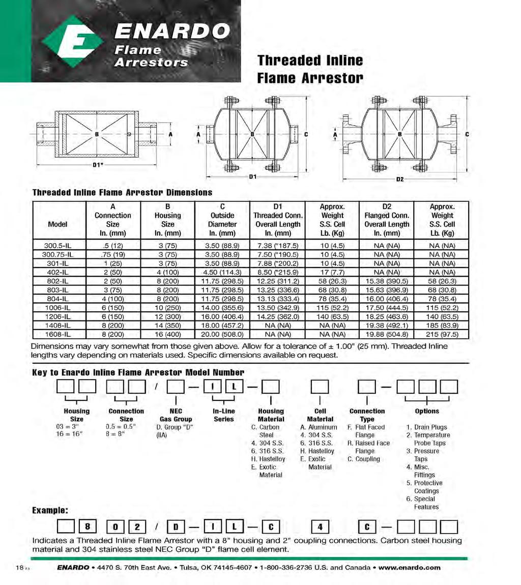
18 SHELL & TUBE TROUBLE SHOOTING GUIDE If the vapor relief valve (PSV-1100) at inlet is relieving pressure, first close valve (BB-001) which will switch the 2 actuated 3-way ball valve (ABV-1200) system by-pass vent to atmosphere. If switching valve (ABV-1200) to by-pass relieves pressure from vapor relief valve, then either mist eliminator (ME-1101) or flame arrestor (FA-1101) may be clogged or obstructed. If switching 2 system by-pass valve (ABV-1200) does not relieve pressure from vapor relief valve, first check operation of JATCO tank. If the tank is dumping by depressing manual dump plunger, check bottom headers, outlets, and tubing for blockage. If the JATCO tank will not dump completely or at all, check for adequate pressure (40 psi) directly at instrument supply inlet of tank. For better performance turn pressure up to (100 psi) max. Also check all downstream lines of the tank for blockage. 244 N.W. 111 th St. Oklahoma City, Oklahoma / / Fax 18
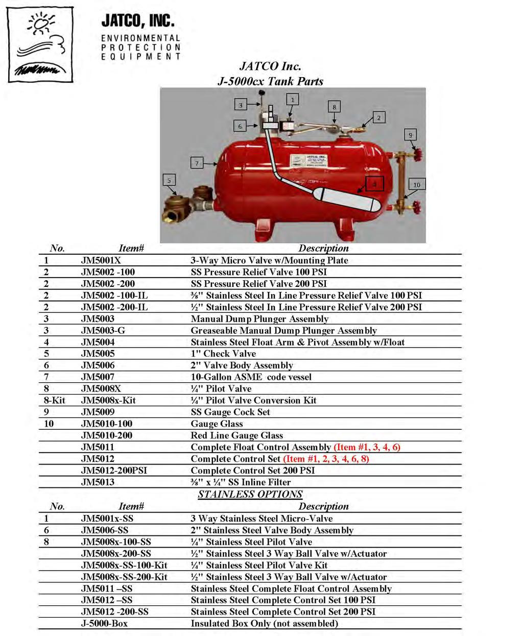
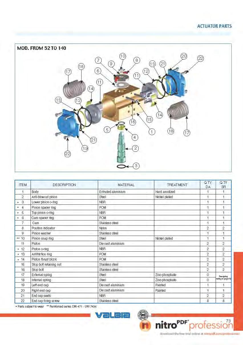
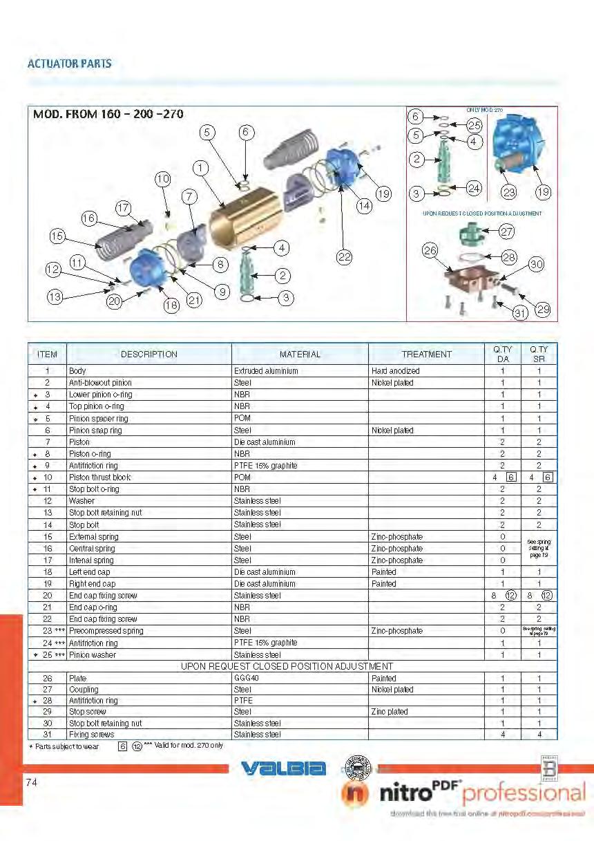
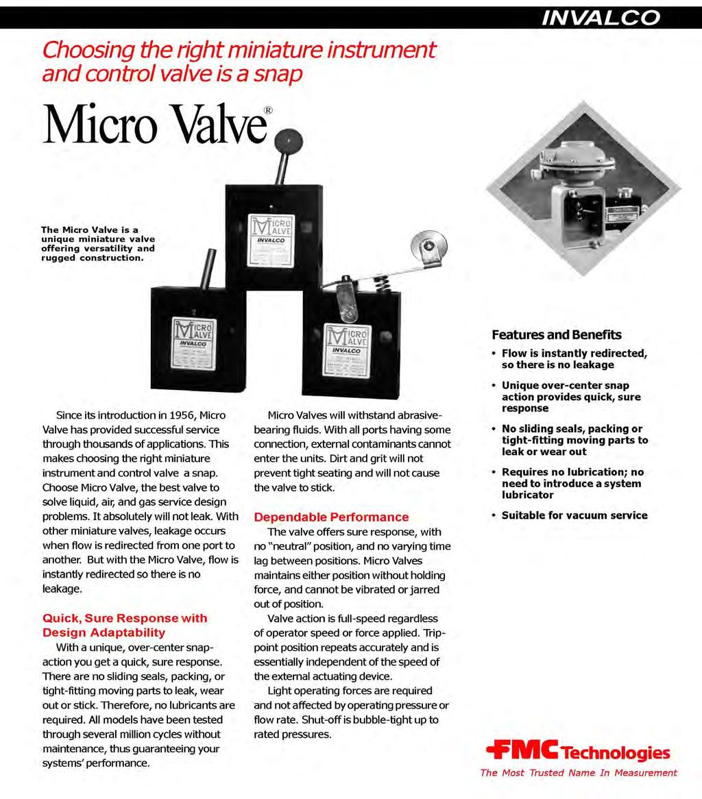
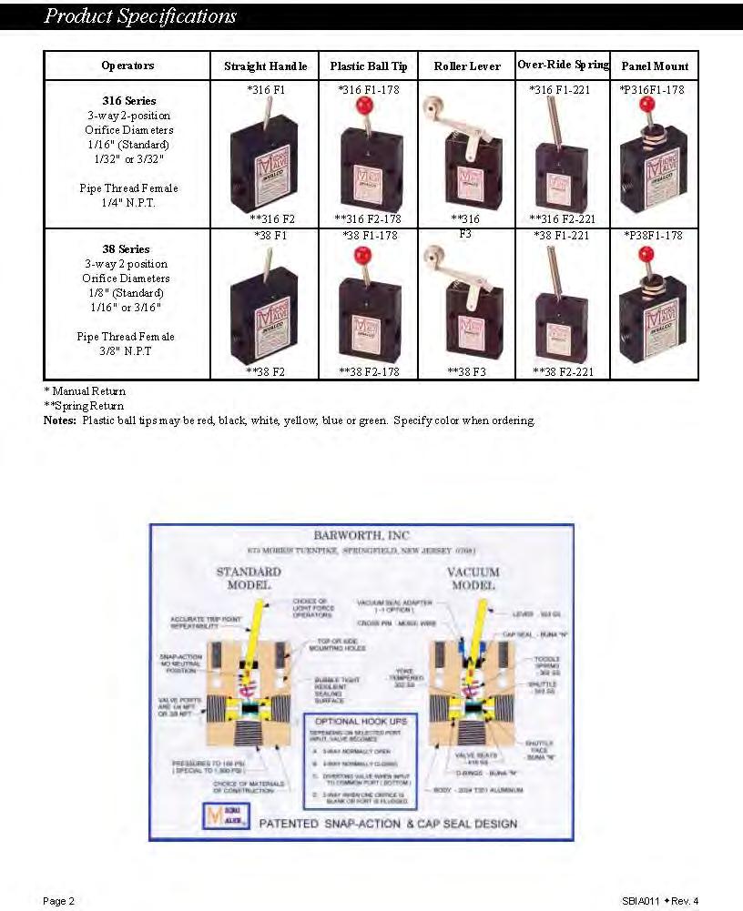
19 RECOMMENDED SPARE PARTS FOR SHELL & TUBE JATCO BTEX ELIMINATOR Qty. Item # Description 1 JM5001X 3 way micro valve for JATCO tank 1 JM5008X ¼ Pilot Valve for JATCO Tank 1 AM100 2 x 6 Stainless Mesh Mist Pad 1 CC01 K-Dyne Manual Reset Valve 1 HQ2 ¼ 3 Way low Pressure Pilot Valve 1 HQ3-R F3002 Humphrey Pilot Valve Repair kit 1 INV F1-B 3 way Micro-Valve for High Level Control 1 ASP19 ½ Actuator Repair Kit 1 ASP29 2 Actuator Repair Kit Contact JATCO Inc. for replacement parts 244 N.W. 111 th St. Oklahoma City, Oklahoma / / Fax 19
20 Service Guide JATCO J-5000CX Environmental Tanks Listed below are a series of steps to follow if the JATCO tank fails to dump properly. Be sure there is an adequate supply of gas pressure ( psi), to the inlet connection on the micro valve. If there is enough pressure at the inlet connection, press down on the manual dump plunger. This should cause the tank to dump, then vent when the cycle is complete. If the JATCO tank fails to dump manually, remove connector tubing to pilot valve (10) to test for pilot pressure from 3 way micro valve (1). If the 3 way micro-valves are not sending pressure to pilot valve when depressing manual dump plunger (#4), removal and or inspection of micro-valve will be necessary and proceed to step #2. If pressure is present but pilot valve fails to operate, removal inspection, and or replacement may be necessary. To remove the micro-valve, remove the top vent tube connector and the bottom gas supply connector to allow access and removal of the two hex socket cap screws. Remove the cap screws and the micro-valve from the valve body. Inspect the inlet port to see if any obstruction has lodged in the orifice which could clog the micro-valve. If no obstruction is visible, apply gas pressure to the inlet port and operate the toggle spring. Flipping the toggle up should allow gas to flow out center ¼ npt port. If operating the toggle does not allow gas to flow, the micro-valve must be replaced. To re-install the micro-valve and mounting plate assembly on the 2 valve body, flip the toggle to the down position and insert toggle spring through the center hole in the valve body. Reinstall the two mounting cap screws, the vent connector, and the gas supply connectors. Check system by depressing manual dump plunger. To remove the install 2 valve body: Remove micro valve as previously described. Remove manual dump plunger. Loosen hex nut on top of valve body and tap down pivot pin. This allows the float arm assembly to swivel while turning valve body out of tank. Remove float assembly carefully to avoid bending the float arm. To install valve body, insert float arm into the tank with the float toward the gauge cock end of the tank. Hold the float pivot with a screwdriver, keeping the slot on the pivot positioned ninety degrees to the float arm. Tighten the 2 valve body into the tank, positioning the machined surface toward the gauge cock end of the tank, while holding the float pivot with a screwdriver; tighten the hex nut to lock the float arm in place. Re-install manual dump plunger and depress it while observing the trip lever through the toggle hold on valve body. The trip lever should be visible and centered. Re-install gasket and micro-valve. 244 N.W. 111 th St. Oklahoma City, Oklahoma / / Fax 20
21 J-5000cx (A) Inlet Check Valve 1 NPT (B) Discharge Check Valve 1 NPT (C) Supply Gas Inlet ⅜ Compression (D) ¼ Screen Vent (E) Pressure Relief Valve (F) Manual Dump Plunger Assembly (G) Three Way Pilot Valve (H) Vessel Vent ¼ NPT (I) Gauge Cocks & Sight Glass 244 N.W. 111 th St. Oklahoma City, Oklahoma / / Fax 21
22 22

23 JATCO Shell & Tube Steam to Liquid Heat Exchangers Completely constructed with 304 stainless steel. Single pass tube construction. Available in 5 O.D. 304 stainless steel shell. Units can be configured in series to increase cooling capacity. Specifications: Test Pressure: 400 psi Operating Pressure: >1 psi Shell (Vapor Side) / 150 psi Tube Sheet (Glycol Side) Max Operating Temp: 225 F Min Operating Temp: 32 F Max Condenser Vapor Outlet Temp: 10 F Approach to Inlet Glycol of the Condenser Shell: 5" Schedule stainless steel pipe Tubes: ½ Diameter.035 Wall 304 stainless steel Tube Length: 72" - 120" No. of Tube Cooling Model # Passes Diameter Bundle Length Surface S.T " 72" sq. ft. S.T " 120" sq. ft. S.T Duplex 2 5" 120" sq. ft. S.T Triplex 3 5" 120" sq. ft. 244 N.W. 111 th St. Oklahoma City, Oklahoma / / Fax 23
24 24
25 25
26 26
27 27
28 28
29 29
30 30
31 31
32 32

33 33
34 34
35 35
36 36
37 37
38 38
39 39
40 40
41 41
42 JATCO Low Pressure 2 Liquid Separator A = 5 CAP B = 5 SCH 10 CAP C = CLASS HALF COUPLING D = ½ FULL COUPLING E = 5 x 1/8 FLAT BAR 244 N.W. 111 th St. Oklahoma City, Oklahoma / / Fax 42
43 43
44 44
45 45
46 46
47 47
48 48
49 49
50 50

51 JATCO Part #TVT N.W. 111 th St. Oklahoma City, Oklahoma / / Fax 51

52 JATCO Part #TVT N.W. 111 th St. Oklahoma City, Oklahoma / / Fax 52
53 JATCO Part #TVT N.W. 111 th St. Oklahoma City, Oklahoma / / Fax 53
54 WARRANTY JATCO, Inc. warrants its products to be free from defects in materials and workmanship, under normal use and service, for a period of one year from the date of shipment. The sole liability and exclusive remedy is limited to the repair or replacement, at the option of JATCO, Inc., of the product, or any parts thereof, which upon examination by JATCO, Inc., disclose to its satisfaction defects due to faulty material or poor workmanship, and which defects are reported to JATCO, Inc., in writing, during the warranty period. The warranty provision contained herein shall not apply to or cover any defects resulting from normal wear and tear, unauthorized changes, repairs, alterations or modifications to the product: or any other causes beyond the control of JATCO, Inc. JATCO, Inc. neither assumes nor authorizes any other person or business organization to assume for it any other warranty or liability in connection with the sale, use or operation of its products. 244 N.W. 111 th St. Oklahoma City, Oklahoma / / Fax 54
55 JATCO INC. OPERATING MANUAL DISCLAIMER Except as otherwise expressly provided in the Warranty section of this manual, JATCO, Inc. does not warrant that the system or any of its components will work properly in all environments or under all conditions and makes no warranty or representation, express or implied, with respect to the quality, performance, merchantability, or fitness for a particular purpose of the system or its components. This operating manual is not intended as an installation guide for the product. This product is intended to be installed by an installation specialist. For a list of such installation specialists please contact JATCO, Inc. In the event the product is not installed by an installation specialist, the warranty provided in the Warranty section of this manual shall not apply to any defects, damage, or other failure of the product to properly function due to improper installation, and JATCO shall have no liability whatsoever for any loss, damage, injury, cost, or expense of any nature arising out of an installation of the product by anyone other than an installation specialist. The information in this manual is subject to change without notice. JATCO, Inc. makes no representations or warranties with respect to the contents of this manual. JATCO, Inc. reserves the right to revise this manual and to make changes from time to time in the content hereof without any obligation of JATCO, Inc. to notify any person of such revisions or changes. It shall be the user s responsibility to determine whether any changes or revisions to this manual have been made. Neither JATCO, Inc. nor any of its directors, shareholders, officers, employees, or agents shall be liable in contract, tort, or in any other manner whatsoever to any person for any loss, damage, injury, liability, cost or expense of any nature, including without limitation, incidental, special, direct, or consequential damages arising out of or in connection with the use of this manual. This manual is proprietary to JATCO, Inc. and no ownership rights in this manual or its contents are transferred to the user. No part of this manual shall be used, reproduced, translated, converted, adapted, stored in a retrieval system, communicated or transmitted by any means, for any commercial purpose, including without limitation, sale, resale, license, rental or lease, without the prior written consent of JATCO, Inc. Any product or component part names used in this manual that are not property of JATCO, Inc. are the properties of the respective owners of such products or component parts and each of JATCO, Inc. and the user acknowledge such ownership. 244 N.W. 111 th St. Oklahoma City, Oklahoma / / Fax 55
Installation Instructions JATCO Environmental Protection Tank Model J-5000CX
 Installation Instructions JATCO Environmental Protection Tank Model J-5000CX The JATCO Environment Tank must be installed at a level which will allow the waste liquids to be disposed of to gravity flow
Installation Instructions JATCO Environmental Protection Tank Model J-7000
 Installation Instructions JATCO Environmental Protection Tank Model J-7000 The JATCO Environment Tank must be installed at a level which will allow the waste liquids to be disposed of to gravity flow into
120 PSI FAST-FILL AIR SOURCE KIT 25% Duty Compressor on 1.5 Gallon Air Tank
 120 PSI FAST-FILL AIR SOURCE KIT 25% Duty Compressor on 1.5 Gallon Air Tank PART NO. 20003 IMPORTANT: It is essential that you and any other operator of this product read and understand the contents of
ULTRA-LIGHT DUTY ONBOARD AIR SYSTEM
 ULTRA-LIGHT DUTY ONBOARD AIR SYSTEM PART NO. 10000 IMPORTANT: It is essential that you and any other operator of this product read and understand the contents of this manual before installing and using
SSFU SUPER SPRAYFAST UNIVERSAL ADHESIVE APPLICATOR
 S S F U SSFU SUPER SPRAYFAST UNIVERSAL ADHESIVE APPLICATOR MACHINERY DIVISION OWNER S MANUAL UNIT INSTRUCTIONS Please follow all SSFU Safety Instructions. Contact your Duro Dyne Tech Service if you have
GETZ EQUIPMENT INNOVATORS RECOVERY SYSTEM CLEAN AGENT FE-36 / HALOTRON 1 PART NO. 4G59751 OPERATIONS MANUAL
 GETZ EQUIPMENT INNOVATORS CLEAN AGENT FE-36 / HALOTRON 1 PART NO. 4G59751 OPERATIONS MANUAL GETZ EQUIPMENT INNOVATORS PEKIN, ILLINOIS, U.S.A. PHONE: (888) 747-4389 FAX: (309) 495-0625 Limited Warranty
480C DUAL PERFORMANCE VALUE PACK
 (Pewter) PART NO. 48012 (Chrome) PART NO. 48032 (Stealth Black) PART NO. 48042 IMPORTANT: It is essential that you and any other operator of this product read and understand the contents of this manual
UNIVERSAL GAS FRYER Instruction Manual Model #8065NS
 Part No. 88847 Revised: August 2004 UNIVERSAL GAS FRYER Instruction Manual Model #8065NS Cincinnati, OH 45241-4807 USA GAS SAFETY PRECAUTIONS OPERATING INSTRUCTIONS UNPACKING AND ASSEMBLY After unpacking
Acid- Rite ph Adjustment System 2500 by Axiall, a Westlake Company
 Acid- Rite ph Adjustment System 2500 by Axiall, a Westlake Company Installation and Operating Instructions DANGER: DO NOT MIX CHEMICALS! The Acid-Rite ph Adjustment System is designed for use with Axiall
TL-12 FLUSH TANK. Manual Ref. # MN-??? Polyurethane Machinery Corp. REVISION 1.0
 TL-12 FLUSH TANK Manual Ref. # MN-??? REVISION 1.0 Polyurethane Machinery Corp. Corporate: 1 Komo Dr, Lakewood, NJ 08701 Manufacturing: 2 Komo Dr, Lakewood, NJ 08701 Phone: 732-415-4400 Fax: 732-364-4025
IMPORTANT SAFETY INSTRUCTIONS
 IMPORTANT SAFETY INSTRUCTIONS CAUTION - To reduce risk of electrical shock or electrocution: - Do not disassemble. Do not attempt repairs or modifications. Refer to qualified service agencies for all service
MEGR-1912 Instruction Manual
 MEGR-1912 PRESSURE REGULATOR Instruction Manual- Look Inside For: Description Installation Start-Up Maintenance Parts Ordering Parts List Marshall Excelsior Company Marshall, MI 49068 269-789-6700 FAX
Model Series 62 Constant Differential Relay
 Siemens Industry, Inc. INSTALLATION AND SERVICE INSTRUCTION INTRODUCTION Model Series 62 Constant Differential Relay Rev 11 March 2011 Supersedes Rev 10 The Constant Differential Relay maintains a constant
ACCU-MIX 1200 / / 26270
 ACCU-MIX 1200 / 14100 / 26270 Model 102006 (1200) Model 102002 (14100) Model 102003 (26270) Pre filter is required when the water supply is from a in house un filtered well to retain the warranty. Pre
GETZ EQUIPMENT INNOVATORS PART NO.: 9G59554 MODEL: MS 36 SC-R HYDROSTATIC TEST PUMP
 GETZ EQUIPMENT INNOVATORS PART NO.: 9G59554 MODEL: MS 36 SC-R HYDROSTATIC TEST PUMP LIMITED WARRANTY Getz Equipment Innovators warrants its products, and component parts of any product manufactured by
GAS DEHYDRATION SYSTEM
 GAS DEHYDRATION SYSTEM High pressure and compressed gases flow to the Glycol Contactor (MAF-3110). In the Contactor, gas flows through trays, contacting the lean glycol that is flowing across the trays
KJ4000 Operating Instructions & Parts Manual NSN
 KJ4000 Operating Instructions & Parts Manual NSN 1025-01-473-7710 Mandus Group Ltd. KJ4000 Operators Manual Date: 3 Jan. 2002 TABLE OF CONTENTS General Safety Instructions...Page 1 Operator Instructions...Page
Float Operated Level Controllers
 CONTENTS Float Operated Level Controllers IM0015 Nov. 2014 PAGE Introduction 1 Scope 1 Description 1 Specification 1 Control Installation 2 INTRODUCTION Side Mount Back Mount Prior to installing, the instructions
Temperature Controllers
 IM0004 April 2013 CONTENTS T-12 Thermostat PAGE Introduction 1 Scope 1 Description 1 Specification 1 Temperature Controllers 2 INTRODUCTION CAUTION Prior to installing, the instructions provided herein
NB/NBR NITROGEN BOOSTER FOR AVIATION SERVICE
 NB/NBR NITROGEN BOOSTER FOR AVIATION SERVICE INSTALLATION, OPERATION & MAINTENANCE MANUAL INTERFACE DEVICES, INC. 230 Depot Road, Milford, CT 06460 Ph: (203) 878-4648, Fx: (203) 882-0885, E-mail: info@interfacedevices.com
INSTALLATION. and INSTRUCTION MANUAL. for QUALITY AIR BREATHING SYSTEMS. Model 50-P-Mini Portable Systems Outfitted with ABM-725 Monitor
 INSTALLATION and INSTRUCTION MANUAL for QUALITY AIR BREATHING SYSTEMS Model 50-P-Mini Portable Systems Outfitted with ABM-725 Monitor M A R T E C H S E R V I C E S C O M P A N Y P.O. Box 7079 OFFICE: (507)
CSA Sample Draw Aspirator Adapter Operator s Manual
 30-0951-CSA Sample Draw Aspirator Adapter Operator s Manual Part Number: 71-0367 Revision: 0 Released: 4/30/15 www.rkiinstruments.com WARNING Read and understand this instruction manual before operating
BS Series Basket Strainer
 BS Series Basket Strainer Operating, Installation, & Maintenance Manual Corrosion Resistant Fluid and Air Handling Systems. Dated 04-26-12 PRESSURE DROP SIMTECH strainers are engineered to offer the lowest
SIX R (P ) AND SEVEN R (P ) POSITION CYLINDERS Service Information
 AND SEVEN R (P ) POSITION CYLINDERS Service Information") SIX R431006322 (P -063892-00001) AND SEVEN R431006321 (P -063981--00002) POSITION CYLINDERS Service Information The six and seven position cylinders are medium duty pneumatic positioning devices that operate
SIX R431006322 (P -063892-00001) AND SEVEN R431006321 (P -063981--00002) POSITION CYLINDERS Service Information The six and seven position cylinders are medium duty pneumatic positioning devices that operate
GETZ EQUIPMENT INNOVATORS PART No. 4G59678 CARBON DIOXIDE MINI PUMP FOR EXTINGUISHER SERVICE (Revised )
") GETZ EQUIPMENT INNOVATORS PART No. 4G59678 CARBON DIOXIDE MINI PUMP FOR EXTINGUISHER SERVICE (Revised 11-24-10) 2320 Lakecrest Drive, Pekin IL 61554 PH. (888) 747-4389 Fax (309) 495-0625 Website: www.getzequipment.com
GETZ EQUIPMENT INNOVATORS PART No. 4G59678 CARBON DIOXIDE MINI PUMP FOR EXTINGUISHER SERVICE (Revised 11-24-10) 2320 Lakecrest Drive, Pekin IL 61554 PH. (888) 747-4389 Fax (309) 495-0625 Website: www.getzequipment.com
Installation and Operation 370ESP (Electric Single-Point Purger) & 370ESPR (Retrofit Purger)
 & 370ESPR (Retrofit Purger)") IB-77 Installation and Operation 370ESP (Electric Single-Point Purger) & 370ESPR (Retrofit Purger) These installation, operation and technical instructions should be used by experienced personnel as a
IB-77 Installation and Operation 370ESP (Electric Single-Point Purger) & 370ESPR (Retrofit Purger) These installation, operation and technical instructions should be used by experienced personnel as a
Index Table. Model 794. Installation, Operating and Maintenance Instructions
 CLOCKWISE MANUAL MAKING INTO CCW TABLE Index Table Model 794 Installation, Operating and Maintenance Instructions Black & Webster Products Division 545 Hupp Ave. P.O. Box 831, Jackson, Michigan 49204 2009
GAS DEHYDRATION SYSTEM
 GAS DEHYDRATION SYSTEM High pressure gases from the Gas Compressors (CBA-4070/4020) flow to the Glycol Contactor (MAF-1150). In the Contactor, gas flows through trays, contacting the lean glycol that is
GAS FRYER Instruction Manual Model #5099NS
 Part No. 89932 Revised: March 2004 GAS FRYER Instruction Manual Model #5099NS Cincinnati, OH 45241-4807 USA GAS SAFETY PRECAUTIONS GAS FUNNEL CAKE FRYER 2 MODEL #5099NS GAS FUNNEL CAKE FRYER SAFETY PRECAUTIONS
RK LEL Sample Draw Aspirator Adapter Operator s Manual
 30-0951RK LEL Sample Draw Aspirator Adapter Operator s Manual Part Number: 71-0017RK Revision: A Released: 6/2/10 www.rkiinstruments.com Product Warranty RKI Instruments, Inc. warrants gas alarm equipment
Installation, Operation and Maintenance Manual for Back Pressure Regulator
 Installation, Operation and Maintenance Manual for Back Pressure Regulator Model 8860 2009 Groth Corporation IOM-8860 Rev. B 12541 Ref. ID: 95565 Page 2 of 13 Table of Contents I. INTRODUCTION 3 II. DESIGN
Model 9201E Tempered Water Blending System
 INSTALLATION, OPERATION & MAINTENANCE INSTRUCTIONS 1455 Kleppe Lane Sparks, NV 89431-6467 (775) 359-4712 Fax (775) 359-7424 E-mail: haws@hawsco.com website: www.hawsco.com Model 9201E Tempered Water Blending
Type S301 & S302 Gas Regulators INTRODUCTION INSTALLATION. Scope of Manual. Description. Specifications. Type S301 and S302. Instruction Manual
 Fisher Controls Instruction Manual Type S301 & S302 Gas Regulators October 1981 Form 5180 WARNING Fisher regulators must be installed, operated, and maintained in accordance with federal, state, and local
Standard Gas Countertop Griddle
 Standard Gas Countertop Griddle This manual contains important information regarding your unit. Please read the manual thoroughly prior to equipment set-up, operation and maintenance. Failure to comply
RK-IR Sample Draw Aspirator Adapter Operator s Manual
 30-0951RK-IR Sample Draw Aspirator Adapter Operator s Manual Part Number: 71-0018RK Revision: A Released: 6/2/10 www.rkiinstruments.com Product Warranty RKI Instruments, Inc. warrants gas alarm equipment
TOP VALVE. Pat. #5,857,486 & 5,944,050. Mid-Range Pressure PSIG Back Pressure and Pressure Relief Valves. Instruction Manual
 TOP VALVE Pat. #5,857,486 & 5,944,050 Mid-Range Pressure 50 232 PSIG Back Pressure and Pressure Relief Valves Instruction Manual Please Note: This instruction manual provides detailed information and instructions
Pressure Dump Valve Service Kit for Series 2300 Units
 Instruction Sheet Pressure Dump Valve Service Kit for Series 00 Units. Overview The Nordson pressure dump valve is used to relieve hydraulic pressure instantly in Series 00 applicator tanks when the unit
Installation Instructions
 LP and High Altitude LP Gas Conversion Kit For United States Installations Installation Instructions For Model Series *G6/PGF1 Furnaces, *L1/PGC1 Furnaces, and *R4/PPG1 Gas/Electric Appliances using Honeywell
MEGR-1627 Instruction Manual
 MEGR-1627 HIGH FLOW GAS REGULATOR Instruction Manual- Look Inside For: Description Installation Remote Vent Line Installations Startup and Adjustment Shutdown Maintenance Body Maintenance Procedures Diaphragm
TITAN FLOW CONTROL, INC.
 PREFACE: This manual contains information concerning the installation, operation, and maintenance of Titan Flow Control (Titan FCI) Simplex Basket Strainers. To ensure efficient and safe operation of Titan
SDS -Series 4C-D201/-D202 Supplemental Drying System User s Manual
 SDS -Series 4C-D201/-D202 Supplemental Drying System User s Manual 8 Executive Drive P.O. Box 2105 Toms River, NJ 08754 (732) 244-0010 (800) 337-3762 fax (732) 244-8140 www.permapure.com info@permapure.com
Model ASSEMBLY and OPERATING INSTRUCTIONS
 QUICK CHANGE AIR BRUSH KIT Model 93506 ASSEMBLY and OPERATING INSTRUCTIONS Due to continuing improvements, actual product may differ slightly from the product described herein. 3491 Mission Oaks Blvd.,
CHEMICAL INDUCTION KIT (Pt.No Issue 6, October 2015)
") CHEMICAL INDUCTION KIT (Pt.No.2400-0740 Issue 6, October 2015) DESCRIPTION The C-Dax Chemical Induction Kit is an accessory kit for the GoldLine range of three point linkage sprayers. The system operates
CHEMICAL INDUCTION KIT (Pt.No.2400-0740 Issue 6, October 2015) DESCRIPTION The C-Dax Chemical Induction Kit is an accessory kit for the GoldLine range of three point linkage sprayers. The system operates
Interface Devices, Inc. Hydraulic Mini Mule
 Interface Devices, Inc. Hydraulic Mini Mule INSTALLATION, OPERATION & MAINTENANCE MANUAL IMPORTANT! FILE THIS MANUAL IN A SAFE PLACE FOR FUTURE SERVICE & PARTS NEEDS ALWAYS REFERENCE THE SERIAL NUMBER
Gas Countertop Hot Plates
 Gas Countertop Hot Plates This manual contains important information regarding your Patriot unit. Please read the manual thoroughly prior to equipment set-up, operation and maintenance. Failure to comply
Model PSI Compressor with 3-Gallon Air Tank 12VDC
 Model 6350 150 PSI Compressor with 3-Gallon Air Tank 12VDC IMPORTANT: It is essential that you and any other operator of this product read and understandd the contents of this manual before installing
RAM 4021 Operation Manual
 RAM 4021 Operation Manual Worldwide Manufacturer of Gas Detection Solutions TABLE OF CONTENTS RAM 4021 For your safety...3 Description...3 Set-up mode...4 Annunciator lights/alarms...4 Operation...5 Calibration...6
INDUSTRIAL VALVES MODELS: C62-A; C62-D. INSTRUCTION MANUAL Installation Operation Parts Service DIAPHRAGM BYPASS PRESSURE REGULATING VALVES
 INSTRUCTION MANUAL Installation Operation Parts Service IMPORTANT Record your Regulator model number and serial number here for easy reference: Model No. Serial No. Date of Purchase When ordering parts
Welker Sampler. Model GSS-1. Installation, Operation, and Maintenance Manual
 Installation, Operation, and Maintenance Manual Welker Sampler Model GSS-1 The information in this manual has been carefully checked for accuracy and is intended to be used as a guide to operations. Correct
GAS DEHYDRATION SYSTEM
 GAS DEHYDRATION SYSTEM High pressure and compressed gases flow through the Gas Scrubber (MBF-4540) to the Glycol Contactor (MAF-0900). In the Contactor, gas flows through trays, contacting the lean glycol
Installation, Operation & Maintenance Manual
 Original Instructions Installation, Operation & Maintenance Manual Sentry VREL Control Valve Pressure Conditioning S-SW-IOM-00277-15 1-17 Table of Contents Safety Information... 3 General Safety Precautions...
R E D I C O N T R O L S
 R E D I C O N T R O L S Operation & Maintenance Manual Portable Service Purger for Low Pressure Chillers Model: PSP-LP-1B For Refrigerants R-11, R-113, R-114 & R-123 & Other Similar Refrigerants File Literature
Accu-Tab PowerBase 3012AT by Axiall Corporation
 Accu-Tab PowerBase 3012AT by Axiall Corporation Installation and Operating Instructions DANGER: DO NOT MIX CHEMICALS! The PowerBase 3012AT chlorinator system is designed for use with Axiall Corp. approved
TECHNICAL DATA. than the water inlet pressure to the concentrate
 Foam102a 1. DESCRIPTION The Viking Low Flow Foam/Water proportioning system, is a UL Listed and FM Approved system, for use with 3M foam concentrates. This system consists of a standard wet pipe sprinkler
WATER HEATER THERMAL EXPANSION TANKS Owner s Manual. Safety Instructions Installation Maintenance Warranty. Models: 2-5 Gallon Capacity
 WATER HEATER THERMAL EXPANSION TANKS Owner s Manual Safety Instructions Installation Maintenance Warranty Models: 2-5 Gallon Capacity Thank You for purchasing this Thermal Expansion Tank. Properly installed
Model C Pipe Line Strainer 6, 8 & 10 Inch (DN150, DN200 & DN250) 250 psi (17,2) General Description. Technical Data. Page of 6 MAY, 2006 TFP1644
 250 psi (17,2) General Description. Technical Data. Page of 6 MAY, 2006 TFP1644") Technical Services: Tel: (00) 31-9312 / Fax: (00) 791-5500 Model C Pipe Line Strainer 6, & 10 Inch (150, & 250) 250 psi (17,2) General Description The welded steel body Model C Pipe Line Strainers (Ref.
Technical Services: Tel: (00) 31-9312 / Fax: (00) 791-5500 Model C Pipe Line Strainer 6, & 10 Inch (150, & 250) 250 psi (17,2) General Description The welded steel body Model C Pipe Line Strainers (Ref.
INSTALLATION MANUAL Matheson Tri-Gas Cabinet Enclosures
 INSTALLATION MANUAL Matheson Tri-Gas Cabinet Enclosures MINT-0289-XX TABLE OF CONTENTS Limited Warranty... 3 User Responsibility... 3-4 General Service... 4 Safety Precautions.... 5 Physical Dimensions..
200 PSI HIGH-FLOW AIR SOURCE KIT
 200 PSI HIGH-FLOW AIR SOURCE KIT 50% Duty Compressor on 2.0 Gallon Air Tank PART NO. 20008 IMPORTANT: It is essential that you and any other operator of this product read and understand the contents of
FloWash. Industrial Filter Cart
 OPERATION AND MAINTENANCE MANUAL FloWash Industrial Filter Cart Read all instructions before installation or operation of equipment. Failure to comply with these instructions could result in bodily injury
TOP VALVE. Pat. #5,857,486 & 5,944,050. High Temperature: max. 300 F (149 C) Back Pressure And Pressure Relief Valves. Instruction Manual
 Back Pressure And Pressure Relief Valves. Instruction Manual") TOP VALVE Pat. #5,857,486 & 5,944,050 High Temperature: max. 300 F (149 C) Back Pressure And Pressure Relief Valves Instruction Manual PLEASE NOTE: This instruction manual provides information and instructions
TOP VALVE Pat. #5,857,486 & 5,944,050 High Temperature: max. 300 F (149 C) Back Pressure And Pressure Relief Valves Instruction Manual PLEASE NOTE: This instruction manual provides information and instructions
DynaPak Gas Sampler S Y S T E M S U P P O R T M A N U A L DP-2000
 DynaPak Gas Sampler S Y S T E M S U P P O R T M A N U A L DP-2000 DP-2000 INSTRUCTION & OPERATING MANUAL Version: 09092002 1 Table Of Contents 1. Introduction 3 2. System Components 3 3. Theory of Operation
Models: C62/63/64-A/D
 Installation & Service C62-991-24A3 Models: C62/63/64-A/D Diaphragm Bypass Pressure Regulating Valves IMPORTANT Record your pump model number and serial number here for easy reference: Model No. Serial
92831 TEL: (714) FAX:
 FAX:") Document N0. 1800-03 Copyright 2010 Terra Universal Inc. All rights reserved. Revised Sept. 2010 Terra Universal, Inc. TerraUniversal.com 800 S. Raymond Ave. Fullerton, CA 92831 TEL: (714) 578-6000 FAX:
Document N0. 1800-03 Copyright 2010 Terra Universal Inc. All rights reserved. Revised Sept. 2010 Terra Universal, Inc. TerraUniversal.com 800 S. Raymond Ave. Fullerton, CA 92831 TEL: (714) 578-6000 FAX:
SAFEsystem. Safety Apparatus Filter Enhancement. Filtration Systems. Now you can safely control your filtering process
 Now you can safely control your filtering process BROCHURE C1 SAFEsystem TM Safety Apparatus Filter Enhancement Available on Individual, Duplex or Multi-Housing ASME Code filter systems. Filtration Systems
DynaPak 2000L System Support Manual Version
 DynaPak 2000L System Support Manual Version 04032001 2 Table Of Contents 1. Introduction 3 2. System Components 3 3. Theory of Operation 4 4. Sampler Location 5 5. Sampler Installation 6 6. Sample Vessel
MODEL NUMBER: PSI AIR SOURCE KIT 200 PSI Compressor on 2.0 Gallon 200 PSI Air Tank
 IMPORTANT SAFETY INSTRUCTIONS CAUTION - To reduce risk of electrical shock or Electrocution: MODEL NUMBER: 20008 200 PSI AIR SOURCE KIT 200 PSI Compressor on 2.0 Gallon 200 PSI Air Tank IMPORTANT: It is
3" UC Ultra-Chuck Durable Lightweight Air Inflated Bladder Chuck Operation/Repair Manual. (76.2 mm) DOUBLE E COMPANY, INC.
 DOUBLE E COMPANY, INC.") 3" UC-3000 (76.2 mm) Ultra-Chuck Durable Lightweight Air Inflated Bladder Chuck Operation/Repair Manual DOUBLE E COMPANY, INC. 319 Manley Street, West Bridgewater, MA 02379 U.S.A. Tel: (508) 588-8099 /
3" UC-3000 (76.2 mm) Ultra-Chuck Durable Lightweight Air Inflated Bladder Chuck Operation/Repair Manual DOUBLE E COMPANY, INC. 319 Manley Street, West Bridgewater, MA 02379 U.S.A. Tel: (508) 588-8099 /
Pressure Dump Valve Service Kit for Series 3000 Units
 Instruction Sheet Pressure Dump Valve Service Kit for Series 000 Units. Overview The Nordson pressure dump valve is used to relieve hydraulic pressure instantly in Series 00, 400, 500, and 700 applicator
OPERATING AND MAINTENANCE MANUAL
 Series 4300 Engineered Performance TABLE OF CONTENTS 0 INTRODUCTION 1 1 Scope 1 2 Description 1 3 Specifications 1 0 INSTALLATION 1 1 Mounting 1 2 Piping 1 1 Connecting Process Pressure 2 2 Vent Connections
Pressure Relief Valve Instruction Manual
 CVR3-M0_062017 Pressure Relief Valve Instruction Manual MODEL: CVR3 SFA Companies 10939 N. Pomona Ave. Kansas City, MO 64153 Tel: 888-332-6419 * Fax: 816-448-2142 E-mail: sales@bvahydraulics.com Website:
97C COMPRESSOR KIT 12V PART NO C COMPRESSOR KIT 24V PART NO C COMPRESSOR KIT PART NO
 97C COMPRESSOR KIT 12V PART NO. 00097 97C COMPRESSOR KIT 24V PART NO. 02497 98C COMPRESSOR KIT PART NO. 00098 97C 98C IMPORTANT: It is essential that you and any other operator of this product read and
FT16 Ball Float Steam Trap Installation and Maintenance Instructions
 1430050/1 IM-P143-04 ST Issue 1 FT16 Ball Float Steam Trap Installation and Maintenance Instructions 1 General safety information 2 General product information 3 Installation ½" and ¾" shown 4 Commissioning
Installation, Operation, and Maintenance Manual
 Installation, Operation, and Maintenance Manual Welker Probe Instrument Regulator Model The information in this manual has been carefully checked for accuracy and is intended to be used as a guide for
MODEL NUMBER: M20005 AIR SOURCE KIT. 30% Duty Compressor on. 2.0 Gallon Air Tank SAVE THIS MANUAL FOR FUTURE REFERENCE
 MODEL NUMBER: M20005 AIR SOURCE KIT 30% Duty Compressor on 2.0 Gallon Air Tank SAVE THIS MANUAL FOR FUTURE REFERENCE USER MANUAL IMPORTANT SAFETY INSTRUCTIONS CAUTION - To reduce risk of electrical shock
92831 TEL: (714) FAX:
 FAX:") Document No. 1800-75 Respiration Test Chamber Copyright 2010 Terra Universal Inc. All rights reserved. Revised September 2010 Terra Universal, Inc. TerraUniversal.com 800 S. Raymond Ave. Fullerton, CA
Document No. 1800-75 Respiration Test Chamber Copyright 2010 Terra Universal Inc. All rights reserved. Revised September 2010 Terra Universal, Inc. TerraUniversal.com 800 S. Raymond Ave. Fullerton, CA
200 PSI FAST-FILL AIR SOURCE KIT
 200 PSI FAST-FILL AIR SOURCE KIT 55% Duty Compressor on 2.0 Gallon Air Tank PART NO. 20007 IMPORTANT: It is essential that you and any other operator of this product read and understand the contents of
LOCK UP VALVES YT-400/405/430/435 SERIES
 LOCK UP VALVES YT-400/405/430/435 SERIES PRODUCT MANUAL VERSION 1.00 Contents 1. Introduction 3 1.1 General information for the users. 3 1.2 Manufacturer Warranty 3 2. Product Description.. 4 2.1 General..
Natural Gas to L.P. Gas Conversion Kit
 Natural Gas to L.P. Gas Conversion Kit For Bosch 80% AFUE Gas Furnace, BGS80 Model Installation Instructions 3124627 2 Natural Gas to L.P. Gas Conversion Kit Installation Instructions Data subject to change
420C AIR COMPRESSOR KIT PART NO C AIR COMPRESSOR KIT PART NO
 420C AIR COMPRESSOR KIT PART NO. 42042 460C AIR COMPRESSOR KIT PART NO. 46043 420C 460C IMPORTANT: It is essential that you and any other operator of this product read and understand the contents of this
IMPORTANT SAFETY INSTRUCTIONS
 IMPORTANT SAFETY INSTRUCTIONS CAUTION - To reduce risk of electrical shock: - Do not disassemble. Do not attempt repairs or modifications. Refer to qualified service agencies for all service and repairs.
Installation, Operation, and Maintenance Manual
 Installation, Operation, and Maintenance Manual Welker The information in this manual has been carefully checked for accuracy and is intended to be used as a guide for the installation, operation, and
Tri-Safem Model I1 Regulator. INSTRUCTIONS and PARTS
 Tri-Safem Model I1 Regulator INSTRUCTIONS and PARTS USER RESPONSIBILITY This equipment will perform in conformity with the description thereof contained In this manual and accompanying labels andlor inserts
ACCESSORY KIT INSTALLATION INSTRUCTIONS
 ACCESSORY KIT INSTALLATION INSTRUCTIONS 1NP0680 - PROPANE CONVERSION FOR USE WITH MODELS: PM8, PC8, PM9, PC9, FL9M, FL9C, FC9M, FC9C This conversion kit is to be installed by a qualified service agency
Model B-1 Pipe Line Strainer 3, 4, 6 & 8 Inch (DN80, DN100, DN150 & DN200) 175 psi (12,1 bar) General Description. Technical Data
 175 psi (12,1 bar) General Description. Technical Data") Technical Services: Tel: (800) 381-312 / Fax: (800) 71-5500 Customer Service/Sales: Tel: (215) 362-0700 / (800) 523-6512 Fax: (215) 362-5385 Model B-1 Pipe Line Strainer 3,, 6 & 8 Inch (DN80, DN100, DN150
Technical Services: Tel: (800) 381-312 / Fax: (800) 71-5500 Customer Service/Sales: Tel: (215) 362-0700 / (800) 523-6512 Fax: (215) 362-5385 Model B-1 Pipe Line Strainer 3,, 6 & 8 Inch (DN80, DN100, DN150
250C-IG COMPRESSOR KIT 12V PART NO C-IG COMPRESSOR KIT 24V PART NO
 250C-IG COMPRESSOR KIT 12V PART NO. 25050 250C-IG COMPRESSOR KIT 24V PART NO. 25058 IMPORTANT: It is essential that you and any other operator of this product read and understand the contents of this manual
250C-IG COMPRESSOR KIT 12V PART NO C-IG COMPRESSOR KIT 24V PART NO
 250C-IG COMPRESSOR KIT 12V PART NO. 25050 250C-IG COMPRESSOR KIT 24V PART NO. 25058 IMPORTANT: It is essential that you and any other operator of this product read and understand the contents of this manual
Discontinued. Powers Controls. Technical Instructions Document No P25 RV Rev. 1, May, RV 201 Pressure Reducing Valves.
 Powers Controls RV 201 Pressure Reducing Valves Description Features Product Numbers Dual Pressure PRV Technical Instructions Document No. 155-049P25 RV 201-1 Single Pressure PRV The RV 201 Pressure Reducing
200 PSI COMPRESSORS - MODEL NUMBERS
 200 PSI COMPRESSORS - MODEL NUMBERS 380C AIR COMPRESSOR KIT PART NO. 38033 480C AIR COMPRESSOR KIT PART NO. 48043 380C 480C IMPORTANT: It is essential that you and any other operator of this product read
Yoke Block Instruction Manual
 Yoke Block Instruction Manual ! WARNING IMPORTANT: READ MANUAL COMPLETELY BEFORE OPERATING THIS DEVICE This manual contains instructions on periodically required checks to be performed by the user. These
AIR INLINE METAL SHEAR
 AIR INLINE METAL SHEAR ASSEMBLY and OPERATING INSTRUCTIONS 3491 Mission Oaks Blvd. / Camarillo, CA 93011 Copyright 1997 by Harbor Freight Tools. All rights reserved. No portion of this manual or any artwork
100C Air Compressor Kit
 10010 100C Air Compressor (standard mounting bracket, CE Spec) 10014 100C Air Compressor (no leader hose or check valve, CE Spec) 10016 100C Air Compressor (with Omega Bracket, CE Spec) IMPORTANT: It is
Back Pressure Regulator
 Instructions Parts List STAINLESS STEEL, WATERBASE COMPATIBLE Back Pressure Regulator 308401E For use in circulating systems to provide regulated back pressure to spray gun(s) and to maintain proper system
1805 Series Relief Valves
 Instruction Manual Form 1211 1805 Series October 2011 1805 Series Relief Valves! WARNING Failure to follow these instructions or to properly install and maintain this equipment could result in an explosion
Compact Triple Cabinet Outlet Station Model B Installation and Operating Instructions
 PORTER Parker Hannifin Corporation Porter Instrument Division 245 Township Line Rd. P.O. Box 907 Hatfield, PA 19440-0907 USA (215) 723-4000 / fax (215) 723-5106 Compact Triple Cabinet Outlet Station Model
Compact Triple Cabinet Outlet Station Model Installation and Operating Instructions
 Compact Triple Cabinet Outlet Station Model 6258-1 Installation and Operating Instructions The Porter Compact Triple Outlet Station (6258-1) provides a quick, safe, and reliable method of connection to
APCO ASU-SCAV & ASU-CAV SINGLE BODY COMBINATION AIR VALVES
 APCO ASU-SCAV & ASU-CAV SINGLE BODY COMBINATION AIR VALVES Instruction D12039 December 2015 Instructions These instructions provide installation, operation and maintenance information for the. They are
RULES FOR SAFE FIRING:
 EN THIS AIRGUN IS INTENDED FOR USE BY THOSE YEARS OF AGE OR OLDER. ADULT SUPERVISION REQUIRED. SOFT-AIR-PISTOL PPK/S BLOW BACK RULES FOR SAFE FIRING:. Get to know the single parts of your new soft-air
Installation and Operating Manual
 Safety Instructions Important Information Please read prior to installation ATTENTION! ELECTRICAL HAZARD FOR INGROUND POOLS AND ABOVEGROUND POOLS Installation and Operating Manual IMPORTANT Pool Owner,
Cocoa Patio Pond with Lit Spillway
 Cocoa Patio Pond with Lit Spillway REMINDER CALL 1-888-755-5641 BEFORE RETURNING TO STORE. PACKAGE CONTENTS ITEM # GQSPPB/GQSPPW Questions, problems, missing parts? Before returning to your retailer, call
EASTERN ENERGY SERVICES PTE LTD. 60 Kaki Bukit Place #02-19 Eunos Tech Park Singapore, SG Singapore Telephone: Fax:
 2 Table Of Contents 1. Introduction 3 2. About this Manual 3 3. Contacting YZ Systems 3 4. Vessel Components 4 5. Specifications 5 6. Application 6 7. Theory of Operation 7 8. DuraSite Installation & Use