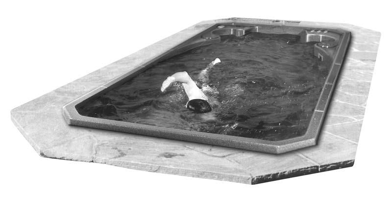
swim spa owner s manual HYDROPOOL Hydropool Inc.:
|
|
|
- Corey Allen
- 5 years ago
- Views:
Transcription


1 HYDROPOOL swim spa owner s manual Hydropool Inc.: Tel: Toll Free: Fax: info@hydropoolhottubs.com BJAA
2 TABLE OF CONTENTS Letter of Introduction...3 Important User Safety instructions Warnings...4 Hyperthermia...4 Choosing the Right Location Indoor Locations...5 Outdoor Locations...5 General Installation Considerations...6 Special Considerations Indoor Installations...6 Outdoor Installations...6 Site Preparation Above Ground Installations...7 In-ground & Partial In-ground Installations...7 Equipment Accessibility & Protection...8 Remote Equipment Remote Equipment Placement...9 Above-Grade Equipment Placement...9 Remote Equipment Plumbing Diagrams...9 Unloading/Handling Your Swim Spa...10 Leveling Your Hydropool Swim Spa...11 Set-up and Assembly Steel Support Leg Assembly Overview...11 Steel Support Leg Assembly Details...12 Support Equipment Assembly...13 Ozonator Connection...13 LED Light Assembly...14 TopSide Control Panel Connection...14 Important Electrical Safety Instructions GFCI / RCD Application Guide & Wire Size...14 North America GFCI installation...15 Europe R.C.D. installation...16 Swim Jets Pump(s) Timer Europe Only...17 Accessories Corner Wrap Pillow...18 AquaCord Tether System/ Rowing kit...18 Filter Cover...18 Waterfall Pillows (FX model only) Your Dream Scents Aromatherapy System Safety Hard Cover Locks...19 LED Mood Lighting...19 Rowing Kit...19 Cover Remover Optional...19 Everlast four-tier steps...19 Filling, Checking and Starting Your Swim Spa...20 Pump Priming/Releasing an Air Lock...21 Hydropool Control Systems North America and Europe AquaTrainer and AquaSport Series...22 AquaSport Series...26 Diagnostic Messages...27 Topside Control Panel Display Messages...28 Jet and Feature Operation Jet Water Flow Adjustment...30 Jet Air Flow Adjustment...30 Jet Insert Removal & Replacement...30 Interchanging Jet Inserts...30 Cleaning Stainless Steel Jets and Controls...30 Adjustable Flow Control (Diverter) Valves Self-Cleaning Mode Cabinet Light Swim Spa Water Balance General Overview...32 Initial Fill Glossary of Common Water Maintenance Terms...33 Water Balance Summary Chart...33 Water Balance Troubleshooting...34 Corona Discharge Ozone Technology...35 Routine Swim Spa Maintenance Daily, Weekly, Monthly, Annually...35 Cleaning the Skimmer Basket...35 Cartridge Filter - Removal, Cleaning, Re-Installation...36 Cleaning the Acrylic Surface...36 Safety Hard Cover...36 Changing Your Swim Spa Water...37 Draining Your Swim Spa Water...37 Water Softeners...37 Cabinet Protecting Your Cabinet Wood Finish...38 Cabinet Wing-Locks...38 Winterizing Your Swim Spa...39 General Troubleshooting...40 What to do in the event of Power fluctuations Cold weather power failure
3
4


5
6
7 SITE PREPARATION ABOVE-GROUND INSTALLATIONS Where the swim spa is a stand-alone above-ground installation to be installed in regions where freeze/thaw conditions may occur, a level patio stone or pre-formed paver type base may be sufficient if there is no abutting deck(s) that could be damaged during potential seasonal movement of the ground. The potential drawback to this type of base is that splash water could eventually de-stabilize the ground under the base, with the resultant shift of the support base causing damage to the swim spa structure. For best results, we recommend the installation of a LEVEL concrete pad: Dig out and level the ground cm (8-12 in.) below your desired base level Install cm (4-6 in.) of crushed stone Next, install cm (4-6 in.) of poured concrete Level the concrete and apply a broom-type finish Recommended Minimum Concrete Pad Dimensions With Factory Cabinet & Steps 14 ft. Model 259 cm x 576 cm 102 in x 228 in 17 ft. Model 259 cm x 671 cm 102 in x 264 in 19 ft. Model 259 cm x 711 cm 102 in x 280 in Without Cabinet 239 cm x 488 cm 94 in x 192 in 239 cm x 576 cm 94 in x 228 in 239 cm x 620 cm 94 in x 244 in In regions where freeze/thaw occurs, or where there will be custom decking abutting the swim spa, we recommend the installation of poured concrete footings extending below the frost line beneath the pad to prevent the possibility of future shifting. INSTALLATION EXAMPLES FACTORY INSTALLED PLUMBING 6" GRAVEL WOOD OR CONCRETE DECK STEEL SUPPORTS POURED 4" SLAB (minimum requirement) NATURAL DRAIN OPEN CAVITY NATURAL DRAIN 6" GRAVEL POURED CONCRETE FOOTINGS WOOD OR CONCRETE DECK FACTORY INSTALLED PLUMBING STEEL SUPPORTS POURED 4" SLAB (minimum requirement) IN-GROUND & PARTIAL IN-GROUND INSTALLATIONS When recessing the swim spa all or part way below ground level, a concrete base along with a concrete or wood retaining wall to hold back the earth is suggested. This forms a box or bunker, in which the swim spa is placed. Hydropool does not recommend back-filling full in-ground or partial in-ground installations without the backfillable frame accessory. Bunker Recommended Minimum Interior Dimensions 14 ft. AT/AS 174 in x 93 in 442 cm x 236 cm 17 ft. AT/AS 210 in x 93 in 533 cm x 236 cm 14 ft. IX AT/AS 168 in x 93 in 427 cm x 236 cm 19 ft. FX AT/AS 220 in x 93 in 559 cm x 236 cm It is recommended leaving a 61 cm (24 in) wide crawl-space around the entire unit to ensure adequate accessibility. ALWAYS ensure that there is good drainage, via a properly designed French (gravel) drain system and/or a sump pump, to prevent ground water flooding damage to the support equipment or structure swim spa Install protective waterproof conduit to house light, or topside control cables that will be buried Access for future service must be considered at the time of design and installation. Difficult access can result in supplemental service labour charges not covered by the factory warranty. Consider easily removable deck materials. 7
8
9 REMOTE EQUIPMENT REMOTE EQUIPMENT PLACEMENT The equipment should be located as close to the swim spa as possible to maximize jet performance Whenever possible, install the pump(s) and control with heater below water level to ensure easy priming The distance of the swim spa support equipment from the unit should never exceed 3m (10 ft.) of pipe length, otherwise jet performance will be affected. Piping diameter on pump lines must be 2.5 in. for inlet/ suction pipes and 2 in. for outlet/pressure pipes with minimal use of elbows. Install protective waterproof conduit to house applicable cords or line extensions such as the topside control cables, light wires or ozone tubing. In climates where freeze/thaw occurs we recommend that remote plumbing lines be buried below the frost line and that pipe insulation is applied over all pipes that run from the swim spa to the remote equipment to help maintain energy efficiency. The swim spa equipment is designed for indoor/out of the direct elements use. Your custom enclosure or other structure must be designed to provide protection for the swim spa support equipment from rain, snow, splash water, etc., but still designed in a manner to ensure adequate ventilation. All field installed plumbing must meet minimum sizes as previously outlined in order to conform to regulated standards regarding safe inlet and outlet flows. If required, please call your dealer for more detailed drawings. REMOTE EQUIPMENT PLUMBING DIAGRAMS Inlet/Suction Side Plumbing Connections Outlet/Pressure Side Plumbing Connections D Pump 1 P3 P1 P2 F Pump 1 PACK P1 2 1/2" Dia. 2" Dia. Pump 2 & 3 Pump 2 & 3 P3 P1 P2 2" Dia. 9
10
11
12


 AQUASPORT SUPPORT EQUIPMENT PLATFORM TYPICAL")
 ID ozonator tube is shipped coiled and attached to the back of the swim jets.")
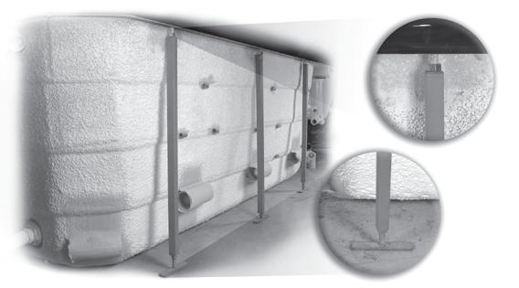
13 SUPPORT EQUIPMENT ASSEMBLY Position equipment platform next to the swim spa under the swim jets. Do not remove support equipment from platform. All necessary o-rings are bundled and shipped in the accessories bag. Carefully install o-rings into unions and hand tighten all connections. Ensure that o-rings are properly seated and do not get pinched while connecting the unions as this will result in leaks. Union connections are located on the swim spa control heater manifold, pipe to pipe connections and all pumps. AQUATRAINER SUPPORT EQUIPMENT PLATFORM TYPICAL (EUROPEAN VERSION SHOWN) AQUASPORT SUPPORT EQUIPMENT PLATFORM TYPICAL (NORTH AMERICAN VERSION SHOWN) Equipment may not be exactly as shown. OZONATOR CONNECTION The clear 9.5 mm (3/8 in) ID ozonator tube is shipped coiled and attached to the back of the swim jets. Attach loose end to barb on ozonator, and ensure that the ozone check valve is oriented vertically. 13

14
15

16
17


 If you received the optional waterfall package, remove the")

18 ACCESSORIES When unpacking your new Hydropool swim spa, you will find an accessories bag inside containing: all necessary o-rings/gaskets gate valve stem locks filter cover #10 expansion plug (for skimmer when draining) Aquacord swim tether (Aquatrainer & Aquasport only) chrome decorative lip trim CORNER WRAP PILLOW The corner wrap pillows are pre-installed at the factory and are attached via pins. To remove, grasp ends of pillow and pull out from hot tub seat. To re-install, reverse procedure. Although the pillows are designed to remain in-place in the swim spa, to extend the life of the pillows, remove after each use. AQUACORD TETHER SYSTEM Sould you desire a tether resistance swim or excercise, simply lift the cap of the Aquacord tether anchor and slip one end of the Aquacord onto the anchor and the other around your waste. Adjust the Aquacord length so that your extended arm has at least 46 cm (18 in.) of clearance from the end of the swim spa. FILTER COVER The filter cover provides that finishing touch to your Hydropool swim spa. To install simply place over the filter opening. WATERFALL PILLOWS (FX model only) If you received the optional waterfall package, remove the blade from the waterfall receiver fitting in the hot tub (already installed at the factory). Insert the waterfall blade through the front of the special waterfall pillow. The front flange of the waterfall blade will be recessed into the front of the pillow. If it is not recessed, the blade needs to be removed and re-inserted through the opposite side of the pillow. Push the pillow into the semi-circular recess, ensuring that the portion of the blade protruding out of the back of the pillow inserts firmly into the waterfall receiver fitting. 18
 To Refill begin by opening the cap counterclockwise on the unit and remove.")


 Mode 3 solid colour blue")

19 YOUR DREAM SCENTS AROMATHERAPY SYSTEM Operational Instructions: This exclusive aromatherapy system is independent from the blower and uses liquid scents. To operate the system is very simple: 1) To Refill begin by opening the cap counterclockwise on the unit and remove. There are arrows on the cap to indicate the direction in which to turn the cap to open. Then fill the reservoir with your favorite Hydropool liquid scent (or equivalent). To replace cap perform the reverse of the above directions. 2) Now the system is ready to work: just push the button to release the scent into the hot tub and repeat to add more liquid scent as desired, please note by turning the button clockwise you can lock it so that any accidental pushing of the button will not result in adding unwanted liquid scent when not desired. To unlock turn button counter-clockwise. WARNING Always ensure the safety hard cover is in place and locked whenever the hot tub is not being used. LED MOOD LIGHTING Press the light pad on the topside control to start the following LED lighting modes. Pressing the light pad on/off within 3 seconds cycles through the various light shows. When the LED lighting is turned off for more than 5 seconds, then turned back on, the system will resume the last light show. Description of Light Shows: Mode 1 Synchronous colour change Mode 2 Freeze mode, freezes on selected colour blend from above mode (gives unlimited colour blend selection) Mode 3 solid colour blue Mode 4 solid colour green Mode 5 solid colour red Mode 6 solid white (simulated) SAFETY HARDCOVER LOCKS In an uncovered swim spa, over 90% of the heat is lost from the water surface. Hydropool hard covers are engineered for maximum thermal efficiency and appearance. Simply place the cover on the swim spa, pull the straps down so that they are fully extended, then release slightly so that there is approximately 6 mm (1/4 in.) of slack. Mark the position on the cabinet or deck surface, and fasten the receiver clip with the screws provided. COVER REMOVER - OPTIONAL A Hydropool cover lifter assists in the removal of the safety hard cover. Please refer to the instructions supplied with your particular cover remover for installation. For further information, contact your local Hydropool retailer. SWIM STEPS To assist in the entry and exit of the swim spa Hydropool offers either a matching three tier Natural Western Red Cedar (pictured in inset above) or a four tier Universal Step in either matching Espresso or Driftwood color with black railings. ROWING KIT The Aquatic Rowing Kit is a combination of stainless steel oars and resistant tether cords that attach to a swivel anchors allowing a full rowing motion. 19


20


21
22 HYDROPOOL SWIM SPA SERIES CONTROL SYSTEMS NORTH AMERICA AND EUROPE HYDROPOOL AQUATRAINER PUMP PRIMING MODE As soon as PRIMING MODE is indicated on the topside panel, push the left pad to start Pump 1 in low speed, then again to switch to high speed. Push the center pad and right pad to start Flashing Pump 2 and *Pump 3 respectively Pump Icon(s) (*Titanium Series only). These are both single speed - high only. All of the pumps will now be operating in high speed to facilitate priming. See FILLING, CHECKING AND STARTING YOUR HOT TUB for complete instructions on pump priming. INITIAL START-UP Before applying voltage to power-up your hot tub, it is very important that you understand the sequence of events that occur when the system is activated in order that the pumps can be primed efficiently and damage to the pumps can be avoided. At initial power-up, this display will appear, and the system will show 4 sets of numbers in succession (ie. 100 then 114 then 28 then 240). These numbers represent the current software revision, and the system input voltage. After the initial software indicators are shown, this display will appear. This display is indicating that the system is in PUMP PRIMING MODE. This mode will last for 4 to 5 minutes before automatically Flashing exiting and entering the normal operation mode. You can also manually exit the PUMP PRIMING MODE after the pumps are primed. While in this mode, the heater circuit is disabled to allow the priming process to be completed without the possibility of energizing the heater element during low flow or no flow conditions. The system will not automatically activate any of the functions, however, by pushing the pads on the topside control, the pumps can be manually activated to facilitate priming. Definition: Priming a pump is a term used to describe the process in which air trapped in the plumbing and pump wet-end (referred to as an air lock ) is released, allowing the pump to move water efficiently through the plumbing system and to the jets. Once pump priming has been successfully completed, press the pads to turn off the pumps. Next, manually exit PRIMING MODE by pressing either the pad or the pad. If you do not manually exit Priming Mode, it will automatically terminate after 4 to 5 minutes. Be sure that the pumps have been primed before exiting this mode. TEMPERATURE CONTROL FUNCTIONALITY AND ADJUSTMENT After you manually exit or the system automatically exits PRIMING MODE, your hot tub will automatically heat to the factory preset default temperature of 38 C (100 F). The topside panel will briefly show the default temperature, and then the display will appear as follows: Flashing Pump 1 Low speed Icon Flashing Pump 1 Low speed Icon Note that the water temperature is not yet displayed, as the system requires approximately 2 minutes of water flow through the heater to determine temperature. This is referred to as polling and is indicated on the display by the icon. After 2 minutes the display will show the current measured water temperature. Press the pad to increase the temperature to the desired setting. The icon will appear on the display indicating that the heater has been activated. In Standard Operating Mode, the system automatically activates Pump 1 low speed every 30 minutes for at least 2 minutes. After 2 minutes, the spa water temperature is determined. At this point, if the water temperature is lower than the set temperature, P1 will continue to run and the icon will appear on the display. The heater will operate until the water temperature reaches the set temperature point, after which, both the heater and Pump 1 low will automatically turn off. 22
23
24


25 LIQUID CRYSTAL DISPLAY (LCD) Continually provides feedback on the operating status of the hot tub. Icons indicate various functions and programming information. LCD INVERT This feature inverts the LCD readout for convenient viewing from inside the hot tub. To invert the readout, Platinum Series: press or then Titanium Series: press To return the LCD readout to normal viewing (from outside of the hot tub), repeat. TOPSIDE PANEL LOCK FEATURES TEMPERATURE LOCK The temperature lock feature prevents unauthorized temperature adjustment of the hot tub water. When the temperature lock is activated, all automatic functions will continue to operate normally. The following pads must be pressed within 3 seconds of each other to activate the lock: then then P1 then TEMPERATURE UNLOCK The following pads must be pressed within 3 seconds of each other to deactivate the lock: then then P1 then When locked, the TL (Temperature Lock) light on the left side of the topside control panel will illuminate. Only the topside control panel temperature pads will be deactivated. TOPSIDE PANEL FULL LOCK The topside panel lock feature prevents unauthorized use of the hot tub controls. When the topside control panel lock is activated, all automatic functions will continue to operate normally. The following pads must be pressed within 3 seconds of each other to activate the lock: then P1 then TOPSIDE PANEL UNLOCK The following pads must be pressed within 3 seconds of each other to deactivate the lock: then P1 then When locked, the PL light (Panel Lock) on the left side of the topside control panel will illuminate. All of the topside control panel pads will be deactivated except for the pad. STANDBY / DRAIN ASSIST The standby/drain assist feature stops the system from operating automatically, allowing for convenient filter cartridge removal and for safe draining of the hot tub. The following pads must be pressed within 3 seconds of each other. The system will automatically exit Standy Mode after 1 hour and resume normal operating functions. Press then the P2 pad and the display will flash: or If the system is heating when Standby Mode is activated, will flash on the display and the pump will continue to operate for 15 seconds to allow the heater to cool off before stopping. All functions will turn off, but P1 low speed can be activated (by pressing the P1 pad) to facilitate draining the hot tub and the display will show or Press any pad other than the P1 pad to return the system to normal operation. See section DRAINING YOUR HOT TUB for detailed instructions. LED MOOD LIGHTING Press the pad on the topside control to start the selection of LED lighting modes. Pressing the pad on/off within 3 seconds cycles through the various light shows. When the LED lighting is turned off for more than 5 seconds, then turned back on, the system will resume the last light show. The system will automatically turn off the mood lighting after 4 hours. OZONATOR OPTIONAL The ozonator operates during FILTER CYCLES and CLEAN UP CYCLES only. The display will show the O3 icon while the ozonator is operating. Pressing any pad on the topside control panel will suspend ozonator function for 1 hour. FREEZE PROTECTION If the temperature sensor detects a drop to 4 C (39 F) within the heater chamber, the system automatically activates the pumps to provide freeze protection. The pumps will operate until the temperature reaches 5 C (41 F) before returning to normal system mode. VARIABLE AIR THERAPY SYSTEM (VATS) - Factory installed Press this pad to turn the (VATS) on and off. The system will automatically turn off the blower after 15 minutes VARIABLE SPEED BLOWER CONTROL FUNCTIONS: 1) ON/OFF : Press 1: The Blower starts at maximum Speed. LED: ON Press 2: The blower stops. LED: OFF 2) TO CONTROL SPEED: Press 1 and hold: Speed goes up or down, LED: ON when pressing. Release pressure at the desired speed. 3) TO CONTROL PULSATION: Press 1: Slow Pulsation Cycle, LED: ON. Press 2: Quick Pulsation Cycle, LED: Flashes. Press 3: Pulsation Cycle OFF, LED: OFF. 25
26
27
28
29


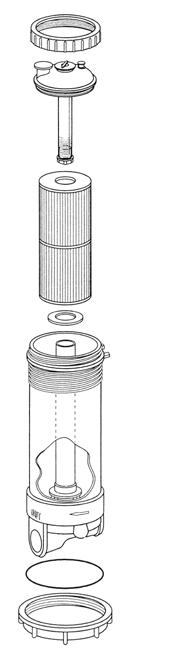
30 JET AND FEATURE OPERATION Cluster Storm Directional Jet Cluster Storm Pulsator Jet Cluster Storm Rifle Jet Mini Storm Galaxy Jet Mini Storm Massage Jet Mini Storm Multi Massage Jet Mini Storm Directional Jet Poly Storm Acupressure Jet Poly Storm Multi massage Jet Poly Storm Rifle Jet Power Storm Resonator Jet Power Storm Rifle Jet Power Storm Twin Roto Jet Monsoon Jet Patented Wide Stream Jet JET WATER FLOW ADJUSTMENT Your Hydropool swim spa features adjustable water flow on specific hydrotherapy jets. To reduce the flow: grasp the outer flange of the jet, and turn clockwise approximately a 1/4 turn. When it hits the stop, the jet is considered closed, and flow will be restricted. To increase the flow: from the closed position, turn the jet counter-clockwise approximately 1/4 turn. When it hits the stop, the jet is open, and there is maximum jet flow. Do not attempt to turn the jet past the stop, as this will unclip the JET AIR FLOW ADJUSTMENT Your Hydropool swim spa features adjustable air flow on specific hydrotherapy jets. To reduce the flow: turn the handle on the air control clockwise. When it hits the stop, the air is closed, and air flow will be restricted. To increase the flow: turn the handle on the air control counter-clockwise. When it hits the stop, the air control is fully opened. For maximum operating efficiency, the air controls must remain closed when your swim spa is not in use. jet internal from the socket. All Hydropool swim spas are shipped from the factory with the jets in the open position. INTERCHANGING JET INSERTS A great feature for custom tailoring the jets in your Hydropool swim spa to suit your personal hydrotherapy needs. Jets of like size and dimension may be interchanged with each other, for example, if you wished to swap a Poly Storm Directional jet for a Poly Storm Twin Roto jet, or a Mini Storm Twin Roto jet for a Mini Storm Directional jet. JET INSERT REMOVAL & REPLACEMENT POLY/MINI STORM DIRECTIONAL & TWIN ROTO POWER STORM MASSAGE & STORM CLUSTER TO REMOVE: Turn the jet counter-clockwise to unclip & pull out of socket. TO RE-INSTALL: Push the jet into the socket until it snaps into place, ensuring the square pin on the back of the jet lines-up with the groove in the socket flange. Rotate jet right or left to ensure it is properly seated. CLEANING STAINLESS STEEL JETS & CONTROLS: Use a Cleaner such as Brasso or Stainless Steel Cleaner to bring back the lustre to your Stainless Steel parts at each refill cycle. 30

31

32
33
34


35
36


37

38

39
40
41
42
TABLE OF CONTENTS. Jet and Feature Operation Letter of introduction 3. Important User Safety Instructions 4 Warnings 5 Hyperthermia 5
 TABLE OF CONTENTS Letter of introduction 3 Important User Safety Instructions 4 Warnings 5 Hyperthermia 5 Choosing the Right location 6-7 Indoor Locations 6 Outdoor Locations 6 General Installation Considerations
TABLE OF CONTENTS Letter of introduction Topside Panel Display Messages
 TABLE OF CONTENTS Letter of introduction 3 Important User Safety Instructions Warnings 4 Hyperthermia 5 Choosing the Right location Indoor Locations 6 Outdoor Locations 6 General Installation Considerations
186 x 93 / 473 cm x cm / cm. 1,944 US gallons / 7,358 L. 18,677 lbs / 8,474 Kg. 2,460 lbs / 1,116 Kg
 186 x 93 / 473 cm x 236.2 cm 48.75 / 123.83 cm 1,944 US gallons / 7,358 L 18,677 lbs / 8,474 Kg 2,460 lbs / 1,116 Kg 46 1/4in ±3/4in (117.48cm ±1.91cm) Height Swim Spa Acrylic Lip 48.75in ±1/2in (123.83
SWIMSPA OWNER S MANUAL
 SWIMSPA OWNER S MANUAL Hydropool Inc. 335 Superior Blvd. Mississauga, ON, Canada L5T 2L6 Tel: 905.565.6810 Toll Free: 1.800.465.2933 Fax: 905.565.6820 Email: info@hydropoolhottubs.com www.hydropoolhottubs.com
150 X 93 / 381 cm x cm* / cm* 1,489 US gallons / 5,635 Liters. 14,403lbs / 6,535 Kg lbs / 900 Kg. * +/- tolerance of 1/4
 150 X 93 / 381 cm x 236.2 cm* * +/- tolerance of 1/4 48.75 / 123.83 cm* 1,489 US gallons / 5,635 Liters 14,403lbs / 6,535 Kg 1984 lbs / 900 Kg 46 1/4in ±3/4in (117.48cm ±1.91cm) Height of Swim Spa
174 x 93 / cm x cm / cm US gallons / 6563 L. 16,766 lbs / 7,607 Kg. 2,302 lbs / 1,044 Kg
 174 x 93 / 441.96 cm x 236.22 cm 48.75 / 123.83 cm 1727 US gallons / 6563 L 16,766 lbs / 7,607 Kg 2,302 lbs / 1,044 Kg 46 1/4in ±3/4in (117.48cm ±1.91cm) Height Swim Spa Acrylic Lip 48.75in ±1/2in
174 x 93 / cm x cm / cm US gallons / 6563 L. 16,766 lbs / 7,607 Kg. 2,302 lbs / 1,044 Kg
 174 x 93 / 441.96 cm x 236.22 cm 48.75 / 123.83 cm 1727 US gallons / 6563 L 16,766 lbs / 7,607 Kg 2,302 lbs / 1,044 Kg 46 1/4in ±3/4in (117.48cm ±1.91cm) Height of Swim Spa Acrylic Lip 48.75in ±1/2in
2018 MODEL. SwimFit / SwimExpert INSTALLATION GUIDE
 2018 MODEL AQUASTREAM SERIES SwimFit / SwimExpert INSTALLATION GUIDE CAUTION: THIS GUIDE IS FOR REFERENCE ONLY! All installations must follow local electrical and building codes. Please consult your local
220 / 93 / 558 / 236 cm / cm US gallons / 9038 L. 22,948 lbs / 10,412 Kg lbs / 1374 Kg
 220 / 93 / 558 / 236 cm 52.75 / 133.99 cm 2378 US gallons / 9038 L 22,948 lbs / 10,412 Kg 3028 lbs / 1374 Kg 50in ±3/4 in (127.00 cm ±1.91cm) Height Swim Spa Acrylic Lip 52 3/4 in ±1/2 in (133.99
Halsey Taylor Owners Manual STOP!
 Halsey Taylor Owners Manual 4710 Freeze Resistant Floor Mounted Steel Fountain STOP! PLEASE READ THE FOLLOWING INFORMATION. ITALLATION ITRUCTIO FOR THE 4710FR FTN. WITH 97243C SINGLE VALVE CONTROL ASSEMBLY
Hydrotherapy Jets System for a Fiberglass Pool
 Page 1 of 5 Parts List 1-50 Flex PVC pipe 2-1 1 / 2 " Ball Valves 4-1/2" 90 degree elbows 4 - Lengths of 1/2" PVC 4 - Jet bodies 4 - Jet nozzles 6 - Female slip/female slip unions 2 - Female slip/fpt union
210 x 93 / cm x cm / cm US gallons / 8259 Litres. 20,830 lbs / 9,451 Kg. 2,627 lbs / 1,192 Kg
 210 x 93 / 533.40 cm x 236.22 cm 48.75 / 123.83 cm 2182 US gallons / 8259 Litres 20,830 lbs / 9,451 Kg 2,627 lbs / 1,192 Kg 46 1/4in ±3/4in (117.48cm ±1.91cm) Height of Swim Spa Acrylic Lip 48.75in
PRE-PURCHASE DECISIONS...1 BEFORE DELIVERY...1
 Table of Contents PRE-PURCHASE DECISIONS...1 BEFORE DELIVERY...1 Typical Installation Site...1 SITE ACCESS...2 COVER...2 ELECTRICAL HOOK UP...3 LOAD SHARING...3 ELECTRICAL REQUIREMENTS...4 North American...4
Halsey Taylor Owners Manual 4410 Freeze Resistant Tubular Fountain STOP!
 Halsey Taylor Owners Manual 4410 Freeze Resistant Tubular Fountain STOP! PLEASE READ THE FOLLOWING INFORMATION. ITALLATION ITRUCTIO FOR THE 4410FR FTN. WITH 97243C SINGLE VALVE CONTROL ASSEMBLY ARE LOCATED
2018 MODEL. SwimFit / SwimExpert INSTALLATION GUIDE
 2018 MODEL SWIMSTREAM SERIES SwimFit / SwimExpert INSTALLATION GUIDE CAUTION: THIS GUIDE IS FOR REFERENCE ONLY! All installations must follow local electrical and building codes. Please consult your local
Installation of Your SprayMaster System
 Installation of Your SprayMaster System 1. At the installation site, remove all equipment from the corrugated box and the polyethylene drum and replace the drum lid. Check the picture to identify each
LUX3 INSTALLATION & SETUP GUIDE INSTALLATION & SETUP GUIDE
 LUX3 INSTALLATION & SETUP GUIDE INSTALLATION & SETUP GUIDE sales@purespas.co.nz 0800 000 827 www.purespas.co.nz TABLE OF CONTENTS 1 Introduction... 03 2 Spa Overview... 04 3 Collection / Delivery & Setup...
Fiber Optic Lighted Bubbler Spillway Pot (DLP-45) Installation Manual
 Installation Manual") Fiber Optic Lighted Bubbler Spillway Pot (DLP-45) Installation Manual 27.75 23.75 25.50 20.75 Specifications: 8-13 GPM 100 strand fiber - Bubbler 75 strand fiber - Spillway Light Bar 45 ft. fiber tail
Fiber Optic Lighted Bubbler Spillway Pot (DLP-45) Installation Manual 27.75 23.75 25.50 20.75 Specifications: 8-13 GPM 100 strand fiber - Bubbler 75 strand fiber - Spillway Light Bar 45 ft. fiber tail
BRILLIANT WONDERS LED BUBBLERS INSTALLATION INSTRUCTIONS CMP SERIES. Brilliant Wonders LED BUBBLERS
 R BRILLIANT WONDERS LED BUBBLERS INSTALLATION INSTRUCTIONS CMP 25503 SERIES Brilliant Wonders LED BUBBLERS TABLE OF CONTENTS 1. Product Overview....3 1.1 Specifications. 3 1.2 Packing List...3 2. System
BRILLIANT WONDERS LED BUBBLERS INSTALLATION INSTRUCTIONS & PRODUCT MANUAL CMP SERIES
 BRILLIANT WONDERS LED BUBBLERS INSTALLATION INSTRUCTIONS & PRODUCT MANUAL CMP 25503 SERIES TABLE OF CONTENTS A. PRODUCT OVERVIEW A.1 SPECIFICATIONS A. PRODUCT OVERVIEW... 3 A.1 Specifications A.2 Packing
PAGE (Rev. A - 06/17)
") Owners Manual Models 4420BF1UDBFR* and 4420BF1LDBFR* Bi-Level Tubular Bottle Filler Fountain with Pet Fountain and Sanitary Freeze Resistant Triple Valve Control Assembly MODEL (LK)4420BF1UDBFR MODEL (LK)4420BF1LDBFR
Owners Manual Models 4420BF1UDBFR* and 4420BF1LDBFR* Bi-Level Tubular Bottle Filler Fountain with Pet Fountain and Sanitary Freeze Resistant Triple Valve Control Assembly MODEL (LK)4420BF1UDBFR MODEL (LK)4420BF1LDBFR
INSTALLATION & START-UP INSTRUCTIONS. Clack WS1 & WS1.25 METER WATER SOFTENER SYSTEMS
 INSTALLATION & START-UP INSTRUCTIONS Clack WS1 & WS1.25 METER WATER SOFTENER SYSTEMS 1999-2009 QualityWaterForLess.com - 1 - info@qualitywaterforless.com Preface: Thank you for your purchase of a new Water
ETL listed for installations within 5 ft. (1.5M) of outer edge of water
 of outer edge of water") Color Light Streams Lighted Super Bubbler Kit Gunite CLSSBK SAVE THESE INSTRUCTIONS! SR Smith Color Light Streams Lighted Super Bubbler is a very simple device to provide lighted water for small fountains
Color Light Streams Lighted Super Bubbler Kit Gunite CLSSBK SAVE THESE INSTRUCTIONS! SR Smith Color Light Streams Lighted Super Bubbler is a very simple device to provide lighted water for small fountains
ENJOY QUALITY LIFE WITH SOURCECORP/S&G
 FACTORY DIRECT SPAS ENJOY QUALITY LIFE WITH SOURCECORP/S&G WA OUTDOOR SPAS As time has proven, hydrotherapy s positive effects on the body and mind are undeniable. Hydrotherapy refreshes, massages and
Bermad Pressure Reducing. Model: 42T
 Bermad Pressure Reducing Pilot Operated Pressure Control Valve Model: 42T Installation Operation Maintenance Manual (IOM) REV. 27.7.17 Page 1 of 12 Safety First BERMAD believes that the safety of personnel
Misaligned Folds Paper Feed Problems Double Feeds Won t Feed FLYER Won t Run iii
 Operator s Manual Table of Contents Operator Safety... 1 Introduction... 2 Unpacking and Setup... 3 Unpacking... 3 Setup... 4 FLYER Overview... 5 FLYER Diagram... 5 Capabilities... 5 Control Panel... 6
LOGO INSTRUCTION MANUAL THE SYMBOL FOR QUALITY AND VALUE
 LOGO INSTRUCTION MANUAL THE SYMBOL FOR QUALITY AND VALUE CONGRATULATIONS!!! Your Nordic Hot Tub represents an innovative and unparalleled Hot Tub design, with unmatched quality, features and value. We
SWIMLIFE OWNER S MANUAL
 SWIMLIFE OWNER S MANUAL Contents subject to change without notice 2018 TABLE OF CONTENTS Letter of introduction 3 Important User Safety Instructions Warnings 4 Hyperthermia 5 Choosing the Right location
SEP 100 D.E. SEPARATION TANK
 SEP 100 D.E. SEPARATION TANK INSTALLATION AND USER S GUIDE IMPORTANT SAFETY INSTRUCTIONS READ AND FOLLOW ALL INSTRUCTIONS SAVE THESE INSTRUCTIONS ii CUSTOMER SERVICE / TECHNICAL SUPPORT If you have questions
A U T O O P E N S E R I E S C A P P R E S S O P E R A T O R S M A N U A L
 A U T O O P E N S E R I E S C A P P R E S S O P E R A T O R S M A N U A L Safety Instructions When using your heat press, basic precautions should always be followed, including the following:.. 3. 4. 5.
CARTRIDGE FILTERS. Models: CF50, CF75, CF100, CF150,
 CARTRIDGE FILTERS Models: CF50, CF75, CF00, CF50, The installation of this product should be carried out by a qualified pool technician, following the installation instructions provided in this manual.
ETL listed for installations within 5 ft. (1.5M) of outer edge of water
 of outer edge of water") Fiberstars Light Streams Mini Laminar Installation Manual (LSML) 3072091 ETL listed for installations within 5 ft. (1.5M) of outer edge of water 79-15056-00 Rev. A Page 1 of 6 SAVE THESE INSTRUCTIONS!
Fiberstars Light Streams Mini Laminar Installation Manual (LSML) 3072091 ETL listed for installations within 5 ft. (1.5M) of outer edge of water 79-15056-00 Rev. A Page 1 of 6 SAVE THESE INSTRUCTIONS!
LoneStar Fiberglass Pools. Do-It-Yourself. Installation Manual
 LoneStar Fiberglass Pools Do-It-Yourself Installation Manual Chris 1/3/2008 Do-It-Yourself The installation of a LoneStar Fiberglass pool is a much simpler task than most people think. What is important
Your Hot Tub Pre-Delivery Guide
 Your Hot Tub Pre-Delivery Guide live better feel better D E L U X E Service Center divinehottubsdeluxe.com Toll Free 1-877-483-1606 customerservice @ divinehottubsdeluxe.com D E LU X E S E R I E S divine
Pressure Dump Valve Service Kit for Series 2300 Units
 Instruction Sheet Pressure Dump Valve Service Kit for Series 00 Units. Overview The Nordson pressure dump valve is used to relieve hydraulic pressure instantly in Series 00 applicator tanks when the unit
User Manual GRI- 1500Li
 User Manual GRI- 1500Li Your Cart Tek caddy cart was thoroughly quality control checked and road tested before being shipped to your address. We do everything possible to assure that your caddy is in perfect
Spas Hotels/Resorts Apartments & Condominiums Campgrounds Health Clubs Medical Clinics Waterparks
 COMMERCIAL HOT TUBS Designed For Spas Hotels/Resorts Apartments & Condominiums Campgrounds Health Clubs Medical Clinics Waterparks HydroTher Mechanical Equipment Packs Mechanical Support Systems Each HydroTher
D E L U X E S E R I E S. Your Hot Tub Pre-Delivery Guide D E L U X E
 Your Hot Tub Pre-Delivery Guide live better feel better D E L U X E Service Center divinehottubsdeluxe.com Toll Free 1-877-483-1606 customerservice @ divinehottubsdeluxe.com divine hot tubs DLX pre-delivery,
Swimming Pools, Hot Tubs and Spas
 OLATHE FIRE DEPARTMENT BUILDING CODES 1225 S. Hamilton Circle Olathe, KS 66061 / Main: (913) 971-7900 / Fax: (913) 971-9812 Swimming Pools, Hot Tubs and Spas Definitions: Swimming Pool- Any structure intended
IMPORTANT SAFETY INSTRUCTIONS READ AND FOLLOW ALL INSTRUCTIONS SAVE THESE INSTRUCTIONS
 Warrior D.E. Filter Operating Procedures IMPORTANT SAFETY INSTRUCTIONS READ AND FOLLOW ALL INSTRUCTIONS SAVE THESE INSTRUCTIONS Table of Contents SECTION I. FILTER INSTALLATION... 1 SECTION II. FILTER
Life Smart Spas Frequently Asked Questions
 Customer Service (888) 961-7727, ahsservice@watkinsmfg.com Life Smart Spas Frequently Asked Questions What makes Lifesmart Spas different from other spas? Lifesmart spas are rotationally molded. This manufacturing
Swim Spa Pre-delivery Guide
 Swim Spa Pre-delivery Guide Hello! This document is designed to provide all the information you need to ensure the smooth delivery and installation of your spa or swim spa. Please read it carefully and
Jacuzzi. J-CQ420 Cartridge Filter Installation and Operating Instructions
 Jacuzzi J-CQ420 Cartridge Filter Installation and Operating Instructions IMPORTANT SAFETY PRECAUTIONS ATTENTION INSTALLER: This guide contains important information about the installation, operation and
Installation and Use Manual
 Installation and Use Manual EMASMB & LMASMB Surface Mount Bottle Filling Stations Model EMASMB IMPORTANT THIS IS AN INDOOR APPLICATION ONLY! ALL SERVICE TO BE PERFORMED BY AN AUTHORIZED SERVICE PERSONNEL.
RESIDENTIAL SWIMMING POOLS AND SPAS A GUIDE FOR HOMEOWNERS
 RESIDENTIAL SWIMMING POOLS AND SPAS A GUIDE FOR HOMEOWNERS City of Redding 777 Cypress Avenue Redding CA 96001 Telephone: (530) 225-4013 FAX: (530) 225-4360 A Swimming Pool is any body of water 18 inches
Performa Cv Twin Alternating and High Flow Systems. Manual Supplement
 Performa Cv Twin Alternating and High Flow Systems Manual Supplement Table of Contents 1.0 Installation and Start-Up.............. 3 Water Line Connection Brine Tank Turbine Connection Connecting Manifold
Instruction Manual Updated 7/26/2011 Ver. 2.2
 4-Unit Model MB HTHP Filter Press #171-50-4: 115-Volt #171-51-4: 230-Volt Instruction Manual Updated 7/26/2011 Ver. 2.2 OFI Testing Equipment, Inc. 11302 Steeplecrest Dr. Houston, Texas 77065 U.S.A. Tele:
FOR INSTALLING CO 2 BLENDER KIT (P/N IN BEER SYSTEM
 IMI CORNELIUS INC One Cornelius Place Anoka, MN 55303-623 Telephone (800) 238-3600 Facsimile (612) 22-326 INSTALLATION INSTRUCTIONS FOR INSTALLING CO 2 BLENDER KIT (P/N 111612000 IN BEER SYSTEM SECONDARY
Installation and Instructions 2. Product Features 3-6. Key Pad Functions 7. Distributor Information Programming Guide 8. Master Programming Guide 9-14
 Installation and Instructions 2 Product Features 3-6 Key Pad Functions 7 Distributor Information Programming Guide 8 Master Programming Guide 9-14 Dimensional Drawing 15 D-STC & D-SMM Valve Assembly 16-17
DRS4-RM Manual. Set Up Instructions for DRS4 Series Single Tank
 Set Up Instructions for DRS4 Series Single Tank Inspect the packaging of the equipment to confirm that nothing was damaged during shipping. (Figure 1) Remove the resin tank(s) and valve(s) from the packaging.
AQUAFIT SYSTEMS. UltraPURE Water Management. 100% 6 Gauge Steel Frame. High Volume Swim Jets. Energy Efficient Full Foam. Patented OptiMounts
 % 6 Gauge Steel Frame UltraPURE Water Management Energy Efficient Full Foam High Volume DuraTex Shell Patented OptiMounts Specifications Terracina Skirt Options Dimensions: 9 x 8 x 5 H Weight : Dry: 3,5
TECHNICAL DATA. Q = C v P S
 Page 1 of 13 1. DESCRIPTION The Viking 6 Model G-6000 Dry Valve Riser Assembly consists of a small profile, light weight, pilot operated valve that is used to separate the water supply from the dry sprinkler
IntelliTouch Pool and Spa Control Systems Smart and simple pool and spa automation
 IntelliTouch Pool and Spa Control Systems Smart and simple pool and spa automation Simple, convenient, and flexible the truly intelligent pool and spa control system. IntelliTouch is the smart system that
PROPORTIONING VALVE. Model 150 INSTRUCTION MANUAL. March 2017 IMS Company Stafford Road
 PROPORTIONING VALVE Model 150 INSTRUCTION MANUAL March 2017 IMS Company 10373 Stafford Road Telephone: (440) 543-1615 Fax: (440) 543-1069 Email: sales@imscompany.com 1 Introduction IMS Company reserves
Pressure Dump Valve Service Kit for Series 3000 Units
 Instruction Sheet Pressure Dump Valve Service Kit for Series 000 Units. Overview The Nordson pressure dump valve is used to relieve hydraulic pressure instantly in Series 00, 400, 500, and 700 applicator
Model: 43T. Bermad Pressure Relief Valve
 Model: 43T Bermad Pressure Relief Valve Installation Operation Maintenance Manual () Rev.C1_01.08.17 Page 1 of 10 Safety First BERMAD believes that the safety of personnel working with and around our equipment
BUBBLER CONTROL SYSTEM
 BUBBLER CONTROL SYSTEM Description: The HDBCS is a fully automatic bubbler system, which does liquid level measurements in water and wastewater applications. It is a dual air compressor system with, air
C.A.I. Customer Service Department 1462 East Ninth Street Pomona, CA Toll Free: CAL-SPAS Fax:
 12/16/2005 CONTACT INFORMATION For customer service, please contact your authorized dealer immediately. If you need additional information and/or assistance, please contact: C.A.I. Customer Service Department
Life Smart Spas Frequently Asked Questions LS600DX
 Customer Service (888) 961-7727, ahsservice@watkinsmfg.com Life Smart Spas Frequently Asked Questions LS600DX What makes Lifesmart Spas different from other spas? Lifesmart spas are rotationally molded.
OWNER S MANUAL ALL 110/120 VOLT PLUG & PLAY SPAS
 OWNER S MANUAL ALL 110/120 VOLT PLUG & PLAY SPAS TABLE OF CONTENTS INTRODUCTION TITLE Page 1. Table of Contents 2 2. Owners Record 3 3. Planning a Location 4 4. A Good Foundation 5 Placing the Hot Tub
LTR , Rev. A 1/28/08
 1/28/08 Read This First! Important Safety Instructions.............. 3 Basic Spa Information.................... 3 Preparing for Your New Spa In-Ground Spa Installation Checklist........ 5 Planning the
The MAXX Press DIGITAL CAP OPERATOR S MANUAL
 The MAXX Press DIGITAL CAP OPERATOR S MANUAL Safety Instructions When using your heat press, basic precautions should always be followed, including the following:.. 3. 4. 5. 6. 7. 8. 9. 0.. Read all instructions.
SWIRLFLO Refrigerated fountains with FLEXI-GUARD
 TM INSTALLATION, CARE & USE MANUAL SWIRLFLO Refrigerated fountains with FLEXI-GUARD TM INSTALLER! CAUTION: Review these instructions before beginning installation. Be sure that installation conforms to
KTM OM-2 SPLIT BODY FLOATING BALL VALVES INSTALLATION AND MAINTENANCE INSTRUCTIONS
 Before installation these instructions must be fully read and understood SECTION 1 - STORAGE 1.1 Preparation and preservation for storage All valves should be properly packed in order to protect the parts
TECHNICAL DATA. Q = C v P S
 Preaction 346a 1. Description The 6 Model G-6000P Electric Release Preaction System Riser Assembly can be used as a Single Interlock Preaction System with Electric Release, or as a Double Interlock Preaction
Type S301 & S302 Gas Regulators INTRODUCTION INSTALLATION. Scope of Manual. Description. Specifications. Type S301 and S302. Instruction Manual
 Fisher Controls Instruction Manual Type S301 & S302 Gas Regulators October 1981 Form 5180 WARNING Fisher regulators must be installed, operated, and maintained in accordance with federal, state, and local
TOWN of CHEEKTOWAGA Permit Application for Swimming Pools, Hot Tubs, or Personal Spas
 Permit Application for Swimming Pools, Hot Tubs, or Personal Spas / 20 - Date of Application Received By Permit No. APPLICANT to COMPLETE the PINK PORTION! ( ) ( ). Applicant s Name Daytime Phone No. Cell
BUBBLER CONTROL SYSTEM
 BUBBLER CONTROL SYSTEM Description: The LDBCS is a fully automatic bubbler system, which does liquid level measurements in water and wastewater applications. It is a dual air compressor system with, air
Check with local zoning official for property line distance requirements.
 RESIDENTIAL POOL PLAN SUBMITTAL GUIDELINES The following guidelines are intended to assist municipal residents with the permit acquisition process with regard to pools, spas and hot tubs for single family
Swimming Pool Requirements
 Swimming Pool Requirements 8040 S. 6th Street Oak Creek, WI 53154 (414) 766-7000 www.oakcreekwi.org Revised: August 8. 2017 PERMITS A permit from the Inspection Department is required prior to putting
TECHNICAL DATA Q = C. v P S. 2 Model G-2000 Dry valve. Page 1 of 13
 Page 1 of 13 1. Description The Viking 2 Model G-2000 Dry Valve Riser Assembly consists of a small profile, light weight, pilot operated valve that is used to separate the water supply from the dry sprinkler
Warmth and water two of the greatest comforts known to the human body. Spa SensatioNZ Range
 Spa SensatioNZ Warmth and water two of the greatest comforts known to the human body. The use of heat and water as a form of relaxation, treatment, rejuvenation and revitalisation is a traditional method
Aqua Pilot Suction Pool Cleaner
 Aqua Pilot Suction Pool Cleaner PL1810 Installation and User Guide Welcome Congratulations on purchasing the PureLine Aqua Pilot Suction Cleaner. Your new Aqua Pilot is guaranteed to provide you with years
LTR , Rev. E 9/26/08
 9/26/08 Read This First! Important Safety Instructions... 1 Basic Spa Information... 1 Preparing for Your New Portable Spa Planning the Best Location.... 3 Preparing a Good Foundation... 3 120 Volt Electrical
Arcadia Spas User Manual
 Arcadia Spas User Manual Dear Spa Buyer, Congratulations on your purchase of a new Arcadia Spa. You now possess the ultimate passport to tranquility a miniature vacation at home, ready and waiting for
You are now the proud new owner of an Alpine Swim Spa!
 Congratulations! You are now the proud new owner of an Alpine Swim Spa! Your Swim Spa will soon be ready and waiting for the whole family to enjoy. This Pre-Delivery guide is designed to ensure that the
INSTALLATION & START-UP INSTRUCTIONS FLECK 9100SXT METER TWIN ALTERNATING WATER SOFTENER SYSTEMS
 INSTALLATION & START-UP INSTRUCTIONS FLECK 9100SXT METER TWIN ALTERNATING WATER SOFTENER SYSTEMS 1999-2007 QualityWaterForLess.com - 1 - info@qualitywaterforless.com Preface: Thank you for your purchase
Poollift Delphin. Version: February, 2015 MANUAL AND OPERATING INSTRUCTIONS
 Poollift Delphin Version: February, 2015 MANUAL AND OPERATING INSTRUCTIONS Content 1. Introduction... 3 2. Technical Specifications... 3 Used materials... 3 3. Installation Instructions... 4 Fastening
TECHNICAL DATA 3 MODEL G-3000 DRY VALVE RISER ASSEMBLY
 Page 1 of 13 1. DESCRIPTION The Viking 3 Model G-3000 Dry Valve Riser Assembly is equipped with a small profile, light weight, pilot operated valve that is used to separate the water supply from the dry
SWIMMING POOL REQUIREMENTS
 PERMITS A permit from the Inspection Department is required prior to putting up a permanent pool. A permit is required for permanent pools, such as the following: SWIMMING POOL REQUIREMENTS The pool is
The purpose of this brochure is to explain to owners and contractors the City of Burnaby s requirements for private swimming pools.
 Building Information BURNABY PLANNING & BUILDING DEPARTMENT Swimming Pools The purpose of this brochure is to explain to owners and contractors the City of Burnaby s requirements for private swimming pools.
Installation and Maintenance Manual. ECO Filtration Unit with 6-way-Top-Mount-Valve. Art. Nr
 Installation and Maintenance Manual ECO Filtration Unit with 6-way-Top-Mount-Valve Art. Nr. 300100 300101 300102 Important Details: - Using of this filtration unit for swimming pools and its guard band
Booster Pump PB4-60 Replacement Kits
 Booster Pump PB4-60 Replacement Kits FOR YOUR SAFETY - This product must be installed and serviced by a contractor who is licensed and qualified in pool equipment by the jurisdiction in which the product
User Manual: Ozone Swim 1000, 2000 and 3000 Series
 User Manual: Ozone Swim 1000, 2000 and 3000 Series P a g e 1 15 Important Safety Information This manual contains important information about the operation and safe use of this product. READ AND FOLLOW
The Perfect Pool. The Perfect Swim.
 The Perfect Pool. The Perfect Swim. www.hydropoolhottubs.com The Perfect Swim The Perfect Family Getaway, All Year Round. Swim Spas by Hydropool are the perfect way to swim every day. Imagine never having
LINDGREN-PITMAN, INC. LS-3 / LS-4 Line Setter
 LINDGREN-PIAN, INC. LS-3 / LS-4 Line Setter MOUNTING The Lindgren-Pitman Line Setter should be mounted on or near the transom of the boat such that the line will fall overboard as it leaves the exit. The
Combination Air Valve
 Combination Air Valve For Sewage and Wastewater Model C50 Installation, Operation and Maintenance Manual (IOM) Table of Contents General... Page 2 Safety... Page 2 Operational Data... Page 3 Materials
TECHNICAL DATA. Q= Cv S
 Page 1 of 13 1. DESCRIPTION The Viking 4 inch Model G-4000 Dry Valve Riser Assembly consists of a small profile, light weight, pilot operated valve that is used to separate the water supply from the dry
INSTALLATION INSTRUCTIONS FOR GRT75-PF-RFS PET FOUNTAIN
 INSTALLATION INSTRUCTIONS FOR GRT75-PF-RFS PET FOUNTAIN Important: Read all instructions and refer to local codes prior to installation. l Local soil conditions may require more gravel for drainage. l
SPA WORLD. Pre- delivery Guide
 SPA WORLD Pre- delivery Guide HELLO! This document is designed to provide all the information you need to ensure the smooth delivery and installation of your spa or swim spa. Please read it carefully and
Budget Range Operators Handbook
 Budget Range Operators Handbook BAMBI AIR COMPRESSORS LTD 152 Thimble Mill Lane Heartlands Birmingham B7 5HT United Kingdom Tel: 0121 322 2299 Fax: 0121 322 2297 Email: sales@bambi-air.co.uk www.bambi-air.co.uk
TECHNICAL DATA. Q = C v P S
 January 6, 2012 Preaction 348a 1. Description Viking supervised Surefire Preaction Systems utilize the Viking G-6000P Valve. The small profile, lightweight, pilot operated Viking G-6000P Valve comes complete
Blue Whale Spa :- Site Preparation and Delivery
 Pre-Delivery Instructions Please take the time to read this information carefully, as it will provide you with the information you will need to ensure the safe, secure, and timely installation of your
Built in the USA Since 1976 Sold in 37 countries around the world
 Built in the USA Since 1976 Sold in 37 countries around the world welcome home In-Fit Exercise Pools are designed to improve the quality of your everyday life. Whether you are an aspiring athlete or simply
LAZY RIVER 3 3 PUMP LOCATION
 .0 1 TEE WITH () " RETURN NOZZLE 1 1.0 10" OR 1 SCH 0 PVC PIPE RETURN WITH ACCELERATOR NOZZLE 2 LAZY RIVER PUMP LOCATION PUMP LOCATION PRELIMINARY SITE LAYOUT AND PUMP LOCATION 1 DETERMINE CURRENT RETURN
Step-by-Step Planning Guide
 B A C K Y A R D P L A N N I N G G U I D E Step-by-Step Planning Guide Whether you are considering purchasing a Michael Phelps Signature Swim Spa by Master Spas, or can t wait for yours to be delivered,
Vortex Spas User Manual
 Vortex Spas User Manual Dear Spa Buyer, Congratulations on your purchase of a new Vortex Spa. You now possess the ultimate passport to tranquility a miniature vacation at home, ready and waiting for you
24L OIL FREE AIR COMPRESSOR MODEL NO: TIGER 7/250 PART NO: OPERATION & MAINTENANCE INSTRUCTIONS LS10/13
 24L OIL FREE AIR COMPRESSOR MODEL NO: TIGER 7/250 PART NO: 2244030 OPERATION & MAINTENANCE INSTRUCTIONS LS10/13 INTRODUCTION Thank you for purchasing this product. Before attempting to use this product,
Assembling & Installing your Pool Cleaner
 Assembling & Installing your Pool Cleaner STEP 1: Check Contents of the Box Remove the Badu Clean Supreme body and all parts from the box and check that the following components are included. Refer to
INSTALLATION, CARE & USE MANUAL. EMASMB & LMASMB Surface Mount Bottle Filling Stations
 INSTALLATION, CARE & USE MANUAL EMASMB & LMASMB Surface Mount Bottle Filling Stations IMPORTANT THIS IS AN INDOOR APPLICATION ONLY! ALL SERVICE TO BE PERFORMED BY AN AUTHORIZED SERVICE PERSONNEL. TOOLS/ITEMS