INSTALLATION & MAINTENANCE INSTRUCTIONS
|
|
|
- Prudence Morgan
- 6 years ago
- Views:
Transcription

1 DESCRIPTION / IDENTIFICATION The QBX series valve uses Proportion-Air closed loop technology for Pressure control. It gives an output pressure proportional to an electrical command signal input. The QB1X is a complete closed loop system consisting of valves, manifold, housing and electronic controls. Pressure is controlled by the use of two solenoid valves. One valve functions as inlet control, the other as exhaust. The pressure output is measured by a pressure transducer internal to the QB1X and provides a feedback signal to the electronic controls. This feedback signal is compared with the command signal input. A difference between the two signals causes one of the solenoid valves to open, allowing flow in or out of the system. Accurate pressure is maintained by controlling these two valves. The QB2X is similar to the QB1X but uses a double loop control scheme. In addition to the internal pressure transducer, the QB2X receives an electrical signal from an external sensing device. This primary feedback signal is compared against the command signal input. This comparison is then summed with the internal pressure transducer signal. The gain of the circuit is such that priority is given to the external feedback signal. A difference between the command signal and the feedback signal causes one of the solenoid valves to be activated. A monitor output is provided for the system measurement. All QBX valves come standard with an analog voltage monitor output. QB1X monitor output is an amplified signal from the internal pressure transducer. QB2X monitor output is a buffered signal from the primary external transducer connected to the QB2X. INSTALLATION INSTALLATION & MAINTENANCE INSTRUCTIONS 1. Apply a small amount of anaerobic sealant (provided) to the male threads of the in-line filter supplied with valve. CAUTION: USE ONLY THE THREAD SEALANT PROVIDED. OTHER SEALANTS SUCH AS PTFE TAPE AND PIPE DOPE CAN MIGRATE INTO THE FLUID SYSTEM CAUSING FAILURES. 2. Install the in-line filter into the port labeled I on QBX valve. 3. For vacuum or vacuum through positive pressure units, the vacuum supply should be connected to the exhaust port of the QBX. 4. Connect supply line to the in-line filter port. Connect device being controlled to port labeled O on QBX valve. 5. For QBX, there are two output ports; one on the size of the manifold and one on bottom. The working port should be determined when ordering; check to ensure that the other port is plugged. 6. Mount valve accordingly. 7. The valve can be mounted in any position without affecting performance. Mounting bracket QBT-01 (ordered separately) can be used to attach valve to a panel or wall surface. 8. Proceed with electrical connections. ELECTRICAL SUPPLY VOLTAGE VDC SUPPLY CURRENT 250 ma COMMAND SIGNAL 0-10 VDC 4-20 ma COMMAND SIGNAL IMPEDANCE VDC=4.75 KΩ Current=100 Ω MECHANICAL PHYSICAL QBX Electro-Pneumatic Pressure Regulator SPECIFICATIONS ANALOGE MONITOR SIGNAL VOLTAGE ma max CURRENT 4-20 ma Sinking (sourcing opt) PRESSURE RANGES Vacuum psig (760 mmhg (Vac) - 12 Bar) OUTPUT PRESSURE 0-100% of range FLOW RATE psig inlet Cv CAPACITY 0.04 Min CLOSED END VOLUME 2 in 3 PORT SIZE 1/8 NPT ( Bar) FILTRATION RECOMMENDED 20 Micron (included) LINEARITY/HYSTERESIS <±0.15% F.S. BFSL REPEATABILITY <±0.02% F.S. ACCURACY <±0.2% F.S. WETTED PARTS ELASTOMERS Fluorocarbon MANIFOLD Aluminum VALVES Nickel Plated Brass PRESSURE TRANSDUCER Silicon, Aluminum OPERATING TEMERPATURE F (0-70 C) WEIGHT 1.02 lb. (0.50 Kg) PROTECTION RATING IP 65 HOUSING Aluminum FINISH Black Anodized Pressure ranges are customer specified. Output pressures other than 100% are available. Others available 1 QBX Installation Guide 5/17/ SSS
2 MONITOR SIGNAL CONFIGURATIONS Voltage Monitor (IE or EE) ELECTRICAL CONNECTIONS 1. Turn off all power to valve. 2. Identify the valve s command input and analog output using the calibration card included in the package and the ordering information section on the last page of this sheet. 3. Proceed to the appropriate section corresponding to the type of valve being installed. NOTE: ALL COLOR CODES RELATE TO THE FACTORY WIRED QBT POWER CORD. COMMAND SIGNAL CONFIGURATIONS VOLTAGE COMMAND VALVES (E, K, V) CURRENT Sinking Monitor (EC or IC) CURRENT COMMAND VALVES (I) CURRENT Sourcing Monitor (ES or IS) 2 QBX Installation Guide 5/17/ SSS

3 QB2X SECOND LOOP CONNECTIONS All QB2 valves are designed to accept a 0-10 volt second loop input signal, unless ordered with special option code C2 (4-20 ma second loop input). Reference the following wiring diagrams for details. ELECTRICAL CONNECTIONS QB2X without 3D Option 1. Turn off all power to valve. 2. Identify the valve s command input and analog output using the calibration card included in the package and the ordering information section on the last page of this sheet. 3. Proceed to the appropriate section corresponding to the type of valve being installed. NOTE: ALL COLOR CODES RELATE TO THE FACTORY WIRED QBT POWER CORD. COMMAND SIGNAL CONFIGURATIONS VOLTAGE COMMAND VALVES (E, K, V) QB2X with 3D Option CURRENT COMMAND VALVES (I) QB2X with C2 Option (ma 2nd loop feedback) 3 QBX Installation Guide 5/17/ SSS

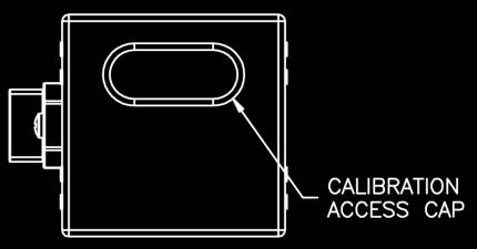
4 RE-CALIBRATION PROCEDURE All QBX control valves come calibrated from the factory by trained personnel using precision calibration equipment. The QBX valve is a closed loop control valve using a precision electronic pressure sensor. Typical drift is less than 1% over the life of the product. If your QBX valve appears to be out of calibration by more than 1%, it is not likely to be QBX. Check the system for plumbing leakage, wiring and electronic signal levels. Verify the accuracy of your measuring equipment before re-calibrating. Consult factory if you have any questions or require assistance. If the QBX valve needs re-calibration, use the procedure described below: QB1X VALVES 1. Identify the inputs and outputs of the valve using the model number of the valve, calibration card included with the valve, and the information provided in this sheet. 2. Connect a precision measuring gage or pressure transducer to the OUT port of the QBX. NOTE: THERE MUST BE A CLOSED VOLUME OF AT LEAST 1 CU. IN. (17 CC) BETWEEN THE VALVE OUTLET AND THE MEASURING DEVICE FOR THE VALVE TO BE STABLE. 3. Connect the correct supply source to the IN port of the QBX, making sure the pressure does not exceed the rating for the valve (See Table 1). 4. Locate the plastic calibration access cap on top of the QBX valve and completely remove it. Located underneath are two adjustment trim pots, Zero Z and Span S. See figure 1 for pots location. 5. NOTE: Only use this step if your device is totally out of calibration. If it is slightly out of calibration, omit this step and move on to paragraph 6. Using a small screwdriver, turn both trim pots 15 turns clockwise. Then turn both trim pots 7 turns counterclockwise. This will put the QB roughly at mid-scale. 6. Make correct electrical connections as noted. Make sure there is a proper meter in place to measure the command input to the QBX. 7. Set the electrical command input to MAXIMUM value. 8. Adjust the SPAN pot until MAXIMUM desired pressure is reached (clockwise increases pressure). 9. Set the electrical command input to MINIMUM value. 10. Adjust the ZERO pot until MINIMUM desired pressure is reached (clockwise increases pressure). 11. Repeat ZERO and SPAN adjustments, which interact slightly, until QB1 Hysteresis Span Zero valve is calibrated back to proper range. Step Replace calibration access cap. FIGURE 1 (QB2X, shown with 3D option) QB2X VALVES This section assumes there is a properly scaled and calibrated transducer for use as 2nd loop feedback signal. For information on re-calibrating Proportion-Air DS series pressure transducers see sheet DS-Installation.pdf 1. Follow, in order, steps 1-5 as noted in the section titled QB1X VALVES. 2. Make correct electrical connections as noted. Make sure there is a proper meter in place to measure the command input to the QB2X. Make sure the 2nd loop signal is connected. 3. Set the electrical command input to MAXIMUM value. 4. Adjust the SPAN pot until MAXIMUM desired pressure is reached (clockwise increases pressure). 5. Set the electrical command input to MINIMUM value. 6. Adjust the ZERO pot until MINIMUM desired pressure is reached (clockwise increases pressure). 7. Repeat ZERO and SPAN adjustments, which interact slightly, until QB2X valve is calibrated back to proper range. Steps Replace calibration access cap. RATED INLET PRESSURE FOR STANDARD QBX VALVES TABLE 1 MAX. calibrated pressure Max. inlet pressure Vacuum up to 10 psig (0.69 bar) Consult Factory 10.1 up to 30 psig (0.70 up to 2 bar) 35 psig (2.4 bar) 31 up to 100 psi (2.1 up to 7 bar) 110 psig (7.6 bar) 101 up to 150 psig (7 up to 10.3 bar) 175 psig (12 bar) 4 QBX Installation Guide 5/17/ SSS
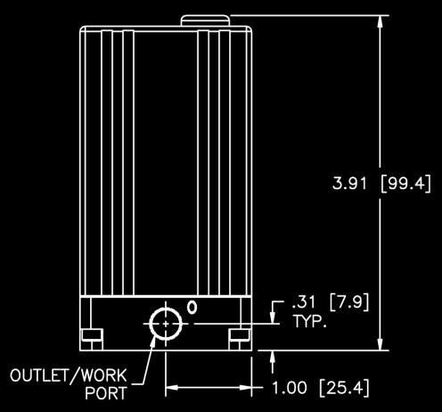
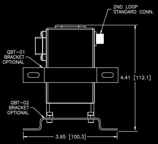
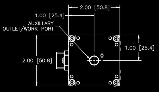
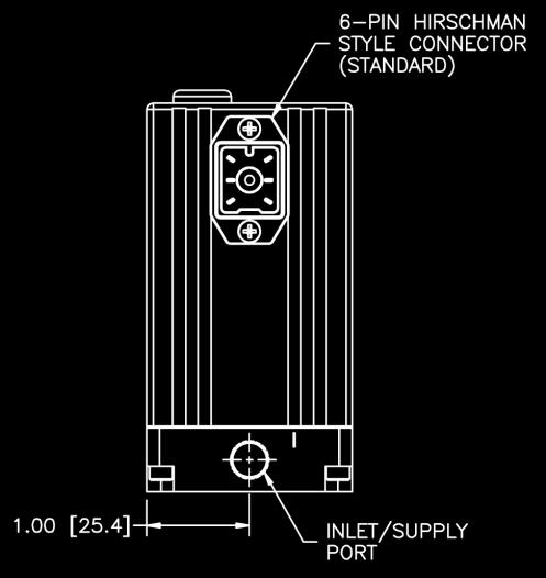
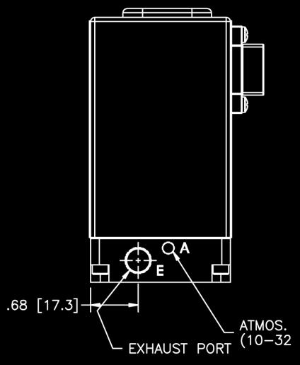


5 DIMENSIONS 5 QBX Installation Guide 5/17/ SSS

6 Safety Precautions Please read all of the following Safety Precautions before installing or operating any Proportion-Air, Inc. equipment or accessories. To confirm safety, be sure to observe ISO 4414: Pneumatic Fluid Power - General rules relating to systems and other safety practices. Warning Improper operation could result in serious injury to persons or loss of life! 1. PRODUCT COMPATIBILITY Proportion-Air, Inc. products and accessories are for use in industrial pneumatic applications with compressed air media. The compatibility of the equipment is the responsibility of the end user. Product performance and safety are the responsibility of the person who determined the compatibility of the system. Also, this person is responsible for continuously reviewing the suitability of the products specified for the system, referencing the latest catalog, installation manual, Safety Precautions and all materials related to the product. 2. EMERGENCY SHUTOFF Proportion-Air, Inc. products cannot be used as an emergency shutoff. A redundant safety system should be installed in the system to prevent serious injury or loss of life. 3. EXPLOSIVE ATMOSPHERES Products and equipment should not be used where harmful, corrosive or explosive materials or gases are present. Unless certified, Proportion-Air, Inc. products cannot be used with flammable gases or in hazardous environments. 4. AIR QUALITY Clean, dry air is not required for Proportion-Air, Inc. products. However, a 40 micron particulate filter is recommended to prevent solid contamination from entering the product. 5. TEMPERATURE Products should be used with a media and ambient environment inside of the specified temperature range of 32 F to 158 F. Consult factory for expanded temperature ranges. 6. OPERATION Only trained and certified personnel should operate electronic and pneumatic machinery and equipment. Electronics and pneumatics are very dangerous when handled incorrectly. All industry standard safety guidelines should be observed. 7. SERVICE AND MAINTENANCE Service and maintenance of machinery and equipment should only be handled by trained and experienced operators. Inspection should only be performed after safety has been confirmed. Ensure all supply pressure has been exhausted and residual energy (compressed gas, springs, gravity, etc.) has been released in the entire system prior to removing equipment for service or maintenance. Caution Improper operation could result in serious injury to persons or damages to equipment! 1. PNEUMATIC CONNECTION All pipes, pneumatic hose and tubing should be free of all contamination, debris and chips prior to installation. Flush pipes with compressed air to remove any loose particles. 2. THREAD SEALANT To prevent product contamination, thread tape is not recommended. Instead, a nonmigrating thread sealant is recommended for installation. Apply sealant a couple threads from the end of the pipe thread to prevent contamination. 3. ELECTRICAL CONNECTION To prevent electronic damage, all electrical specifications should be reviewed and all electrical connections should be verified prior to operation. Exemption from Liability 1. Proportion-Air, Inc. is exempted from any damages resulting from any operations not contained within the catalogs and/or instruction manuals and operations outside the range of its product specifications. 2. Proportion-Air, Inc. is exempted from any damage or loss whatsoever caused by malfunctions of its products when combined with other devices or software. 3. Proportion-Air, Inc. and its employees shall be exempted from any damage or loss resulting from earthquakes, fire, third person actions, accidents, intentional or unintentional operator error, product misapplication or irregular operating conditions. 4. Proportion-Air, Inc. and its employees shall be exempted from any damage or loss, either direct or indirect, including consequential damage or loss, claims, proceedings, demands, costs, expenses, judgments, awards, loss of profits or loss of chance and any other liability whatsoever including legal expenses and costs, which may be suffered or incurred, whether in tort (including negligence), contract, breach of statutory duty, equity or otherwise. Warranty Proportion-Air, Inc. products are warranted to the original purchaser only against defects in material or workmanship for one (1) year from the date of manufacture. The extent of Proportion-Air s liability under this warranty is limited to repair or replacement of the defective unit at Proportion-Air s option. Proportion-Air shall have no liability under this warranty where improper installation or filtration occurred. 6 QBX Installation Guide 5/17/ SSS
INSTALLATION & MAINTENANCE INSTRUCTIONS DESCRIPTION SPECIFICATIONS. CE (EMC) Compliant
 Compliant") INSTALLATION & MAINTENANCE INSTRUCTIONS DESCRIPTION The QB3 is a closed loop pressure regulator consisting of two solenoid valves, internal pressure transducer, and electronic controls mounted to an integrated
INSTALLATION & MAINTENANCE INSTRUCTIONS DESCRIPTION The QB3 is a closed loop pressure regulator consisting of two solenoid valves, internal pressure transducer, and electronic controls mounted to an integrated
INSTALLATION & MAINTENANCE INSTRUCTIONS QBX ETHERNET MODEL
 DESCRIPTION / IDENTIFICATION INSTALLATION & MAINTENANCE INSTRUCTIONS QBX ETHERNET MODEL The QBX series valve uses Proportion-Air closed loop technology for Pressure control. It gives an output pressure
QBS Electronic Pressure Regulator
 INSTALLATION AND MAINTENANCE INSTRUCTIONS DESCRIPTION / IDENTIFICATION The QBS stainless steel series is an electronically controlled pressure regulator. The QBS controls the pressure on its output port
ISQB1 INTRINSICALLY SAFE ELECTRO-PNEUMATIC CONTROL VALVE INSTALLATION & MAINTENANCE INSTRUCTIONS HAZARDOUS AREA CLASSIFICATION
 PROPORTION AIR ISQB1 INTRINSICALLY SAFE ELECTRO-PNEUMATIC CONTROL VALVE INSTALLATION & MAINTENANCE INSTRUCTIONS Hazardous area classification Description / identification General specifications Connection
QBS Electronic Control Valve
 QBS Electronic Control Valve For Pressures Up To 5 psi About Equilibar QBS The Equilibar QBS is an electronic pressure regulator designed to accurately control the pressure of gaseous media proportional
DPC-30 DPC-100. Reference Manual
 DPC-30 DPC-100 Reference Manual 1. Introduction 1.1 Description The Martel DPC Digital Pneumatic Calibrator improves upon traditional dial gauge pneumatic calibrators. The Martel DPC improves accuracy,
GP1 & GP2. Electropneumatic Regulators FOR PRESSURE CONTROL TO 1,000 PSI
 GP1 & GP2 Electropneumatic Regulators FOR PRESSURE CONTROL TO 1, PSI GP1 & GP2 Functional Description The GP series control valve is an electronic pressure regulator designed to precisely control the pressure
Electropneumatic Transducer (I/P) Installation, Operation and
 Installation, Operation and") Nitra NCP1 Series Electropneumatic Transducer (I/P) Installation, Operation and Maintenance Instructions Ordering Information Contents Part Number I/P Transducers Output Range Input psig bar Section Description
Nitra NCP1 Series Electropneumatic Transducer (I/P) Installation, Operation and Maintenance Instructions Ordering Information Contents Part Number I/P Transducers Output Range Input psig bar Section Description
QBX QBS QBT ELECTRO-PNEUMATIC PRESSURE REGULATORS. On-Board Ethernet Option. Accurate & Repeatable. High Pressure Control. Up to 12 bar & 34 Lit/Min
 ELECTRO-PNEUMATIC PRESSURE REGULATORS QBT PRESSURE Vacuum to 175 psig FLOW Up to 1.2 scfm ACCURACY +/- 0.2% full scale Up to 12 bar & 34 Lit/Min QBS PRESSURE Vacuum to 500 psig FLOW Up to 1.2 scfm ACCURACY
E8AA. Pressure Sensor of Stainless Steel Construction Is Ideal for a Wide Range of Applications. Pressure Sensor (Stainless Steel Diaphragm)
") Pressure Sensor (Stainless Steel Diaphragm) CSM DS_E_3_1 Pressure Sensor of Stainless Steel Construction Is Ideal for a Wide Range of Applications Incorporates double diaphragms consisting of SUS316L stainless
Pressure Sensor (Stainless Steel Diaphragm) CSM DS_E_3_1 Pressure Sensor of Stainless Steel Construction Is Ideal for a Wide Range of Applications Incorporates double diaphragms consisting of SUS316L stainless
INSTRUMENT MANUAL VP50 PROPORTIONAL CONTROL VALVE
 INSTRUMENT MANUAL VP50 PROPORTIONAL CONTROL VALVE Watson Smith Instrumentation IMPORTANT SAFETY WARNING CONTENTS Please read these instructions carefully BEFORE this instrument is installed or maintained.
PRODUCT CATALOG ELECTRO-PNEUMATIC PRESSURE REGULATORS & FLOW CONTROLLERS PRESSURE FLOW FORCE TENSION POSITION TORQUE VACUUM
 ELECTRO-PNEUMATIC PRESSURE REGULATORS & FLOW CONTROLLERS PRESSURE FLOW FORCE TENSION POSITION TORQUE VACUUM PRODUCT CATALOG 1 PRESSURE CONTROL QBX, Vacuum-175 PSI, 1.2 SCFM...4-5 QBS, Vacuum-500 PSI, 1.2
Pilot Check Valve: Metal Body Type
 INFORMATION Pilot Check Valve: Metal Body Type The use of a metal body improves strength and environmental resistance. Temporary intermediate stops are possible. *1 *1 Precise intermediate stops are not
Section 2 Proportional Quick Exhaust
 V A L V E S Section 2 Proportional Quick Exhaust OPERATION OF THE PQE 1. The pilot operated regulator and the PPC5C are both fed from a common inlet. 2. The out port of the PPC5C sends pressure to the
THE INSIDE STORY OF THE F-SERIES:
 BRFSERIES15E THE INSIDE STORY OF THE FSERIES: Response Time < 1ms Analog Differential ressure Sensor for Real Time Measurement Analog Output = Measured Flow Many Connector Options I65 Housing ressure Compensated
QBX QBT QBS ELECTRO-PNEUMATIC PRESSURE REGULATORS. On-Board Ethernet Option. Accurate & Repeatable. High Pressure Control. Up to 12 bar & 34 Lit/Min
 ELECTRO-PNEUMATIC PRESSURE REGULATORS QBT QBS QBX PRESSURE Vacuum to 175 psig PRESSURE Vacuum to 500 psig PRESSURE Vacuum to 175 psig FLOW Up to 1.2 scfm ACCURACY +/- 0.2% full scale FLOW Up to 1.2 scfm
BAROMETER PRESSURE STANDARD PRESSURE CONTROLLER
 BAROMETER PRESSURE STANDARD PRESSURE CONTROLLER Features ±0.01% FS Measurement & Control Accuracy ±0.001% /ºC Thermal Stability Pressure Ranges from ±1 psid to 1200 psia Applications Barometric Measurement
TR Electronic Pressure Regulator. User s Manual
 TR Electronic Pressure Regulator Page 2 of 13 Table of Contents Warnings, Cautions & Notices... 3 Factory Default Setting... 4 Quick Start Procedure... 5 Configuration Tab... 8 Setup Tab... 9 Internal
36H SERIES Combination Gas Valve
 FAILURE TO READ AND FOLLOW ALL INSTRUCTIONS CAREFULLY BEFORE INSTALLING OR OPERATING THIS CONTROL COULD CAUSE PERSONAL INJURY AND/OR PROPERTY DAMAGE. DESCRIPTION The 36H series combination gas valve is
Series IRV1000/2000/3000
 CAT.ES60-16 A Regulator Series /2000/3000 Allows adjustment of vacuum line pressure Regulator Series /2000/3000 3 sizes offered in the series Variations have been expanded to three sizes from only one
GAS FUEL VALVE FORM AGV5 OM 8-03
 ALTRONIC AGV5 OPERATING MANUAL GAS FUEL VALVE FORM AGV5 OM 8-03 WARNING: DEVIATION FROM THESE INSTALLATION INSTRUCTIONS MAY LEAD TO IMPROPER ENGINE OPERATION WHICH COULD CAUSE PERSONAL INJURY TO OPERATORS
NB/NBR NITROGEN BOOSTER FOR AVIATION SERVICE
 NB/NBR NITROGEN BOOSTER FOR AVIATION SERVICE INSTALLATION, OPERATION & MAINTENANCE MANUAL INTERFACE DEVICES, INC. 230 Depot Road, Milford, CT 06460 Ph: (203) 878-4648, Fx: (203) 882-0885, E-mail: info@interfacedevices.com
Exercise 8. Closed-Loop Pressure Control, Proportional-Plus-Integral Mode EXERCISE OBJECTIVE
 Exercise 8 Closed-Loop Pressure Control, EXERCISE OBJECTIVE To understand open and closed-loop pressure control; To learn how to sense the pressure in a pneumatic circuit; To control the pressure in a
HAYWARD FLOW CONTROL TFS SERIES FLOW METER INSTALLATION, OPERATION AND MAINTENANCE INSTRUCTIONS
 HAYWARD FLOW CONTROL TFS SERIES FLOW METER INSTALLATION, OPERATION AND MAINTENANCE INSTRUCTIONS PLEASE READ THE FOLLOWING INFORMATION PRIOR TO INSTALLING AND USING HAYWARD TFS SERIES FLOW METERS. FAILURE
Type 3709 Pneumatic Lock-up Valve. Translation of original instructions. Mounting and Operating Instructions EB 8391 EN
 Type 3709 Pneumatic Lock-up Valve Translation of original instructions Mounting and Operating Instructions EB 8391 EN Edition July 2017 Note on these mounting and operating instructions These mounting
Constant Pressure Inlet (CCN) Operator Manual
 Operator Manual") Constant Pressure Inlet (CCN) Operator Manual DOC-0125 Revision J 2545 Central Avenue Boulder, CO 80301-5727 USA C O P Y R I G H T 2 0 1 1 D R O P L E T M E A S U R E M E N T T E C H N O L O G I E S, I
Constant Pressure Inlet (CCN) Operator Manual DOC-0125 Revision J 2545 Central Avenue Boulder, CO 80301-5727 USA C O P Y R I G H T 2 0 1 1 D R O P L E T M E A S U R E M E N T T E C H N O L O G I E S, I
Model PDT Dewpoint Transmitter
 Model PDT Dewpoint Transmitter Instruction Manual Alpha Moisture Systems Alpha House 96 City Road Bradford BD8 8ES England Tel: +44 1274 733100 Fax: +44 1274 733200 email: mail@amsytems.co.uk web: www.amsystems.co.uk
CSA Sample Draw Aspirator Adapter Operator s Manual
 30-0951-CSA Sample Draw Aspirator Adapter Operator s Manual Part Number: 71-0367 Revision: 0 Released: 4/30/15 www.rkiinstruments.com WARNING Read and understand this instruction manual before operating
453 Series Steam Heated Vaporizing Regulator
 ADI 0453A Certified ISO 9001:2000 453 Series Steam Heated Vaporizing Regulator INSTALLATION AND OPERATION INSTRUCTIONS Before Installing or Operating, Read and Comply with These Instructions Controls Corporation
36G22, 36G23, 36G24 & 36G52 36J22, 36J23, 36J24 & 36J52 DSI and HSI Single Stage Combination Gas Valve
 Operator: Save these instructions for future use! FAILURE TO READ AND FOLLOW ALL INSTRUCTIONS CAREFULLY BEFORE INSTALLING OR OPERATING THIS CONTROL COULD CAUSE PERSONAL INJURY AND/OR PROPERTY DAMAGE. DESCRIPTION
L 100. Bubble-Tube Level System. Installation, Operation and Maintenance Instructions
 L 100 Bubble-Tube Level System Installation, Operation and Maintenance Instructions Figure 1 Contents Section Description Page 1.0 Introduction 2 2.0 Specifications 3 3.0 Installation 3 4.0 Warranty 6
Deep Submersible Level Transducer Series 300DS
 KPSI Transducers Deep Submersible Level Transducer Series 300DS FEATURES! Custom Level Ranges up to 4614 ft (1408 m) H 2 O! Accuracy of ±0.5% FS! Analog Outputs of 4-20 ma or 0-5 VDC! Welded 316 SS Construction!
TOP VALVE. Pat. #5,857,486 & 5,944,050. Mid-Range Pressure PSIG Back Pressure and Pressure Relief Valves. Instruction Manual
 TOP VALVE Pat. #5,857,486 & 5,944,050 Mid-Range Pressure 50 232 PSIG Back Pressure and Pressure Relief Valves Instruction Manual Please Note: This instruction manual provides detailed information and instructions
INSTRUCTION MANUAL. FLOW CONTROL DRAWERS MANUAL / PLC CONTROL SERIES Model Version Perma Pure LLC Tel:
 PERMA PURE INSTRUCTION MANUAL FLOW CONTROL DRAWERS MANUAL / PLC CONTROL SERIES Model 3300 Version 4.06 Perma Pure LLC Tel: 732-244-0010 P.O. Box 2105, 8 Executive Drive Tel: 800-337-3762 (toll free US)
VACUUM REGULATORS CONTENTS
 CAD drawing data catalog is available. ACCESSORIES GENERAL CATALOG AIR TREATMENT, AUXILIARY, VACUUM, AND FLUORORESIN PRODUCTS CONTENTS Small Regulators Features 759 Specifications, Order Codes, Flow Rate
RAM Operation Manual. Worldwide Manufacturer of Gas Detection Solutions
 RAM 4021 Operation Manual Worldwide Manufacturer of Gas Detection Solutions TABLE OF CONTENTS RAM 4021 For Your Safety... 2 Description.... 2 Setup Mode.... 2 Lights/Alarms.... 3 Operation.... 4 Calibration....
86BSD Backside Digital Output
 Stainless steel with O-ring seal Pressure/temperature read-out Backside digital output ASIC calibrated Absolute, gage Cable/connector option Low power option DESCRIPTION The 86BSD is a small profile, media
I/P Transducer Positioner Module
 I/P Transducer Positioner Module VRC P/N: 7958032 Installation, Operation and Maintenance Instructions 2.09 [53.1] 1.30 [32.9] 2.97 [75.5] 0.78 [19.8] 0.18 [4.4] 1.42 [36.1] n.18 MOUNTING HOLES (2) PLACES
Electro-Pneumatic Converter YT-940 SERIES
 Electro-Pneumatic Converter YT-940 SERIES PRODUCT MANUAL VERSION 1.00 Contents 1. Introduction 3 1.1 General information for the users. 3 1.2 Manufacturer Warranty 3 1.3 Explosion Proof Warning. 4 2. Product
ERNG-X TESCOM Product Manual
 Instruction Manual TESCOM Product Manual Figure 1. Table of Contents Contents Section 1: Introduction... 2 Section 2: Before You Begin.... 2 2.1 Safety, Installation and Operations Precautions.... 3 2.1.1
2 Overview. SITRANS P measuring instruments for pressure. Transmitters for gage and absolute pressure. Z series for gage pressure
 Z series for gage pressure Overview Design The main components of the pressure transmitter are: Brass housing with silicon measuring cell and electronics plate Process connection Electrical connection
G196 Series BASOTROL Redundant Combination Gas Valve with Manual Shutoff Valve
 Installation Instructions Issue Date August 19, 2008 G196 Series BASOTROL Redundant Combination Gas Valve with Manual Shutoff Valve Application The G196 valves are suitable for use with natural gas, Liquefied
DTG - LCD Digital Temperature Gauge USER MANUAL
 DTG - LCD USER MANUAL Page 1 of 7 USERS GUIDE page 1. Description 3 2. Function 3 3. Safety Instruction 3 3.1. Safety Conventions 3 3.2. Proper Use 3 4. Installation 4 4.1. Unpacking 4 4.2. Storage 4 4.3.
RAM 4021-PR. Operation Manual. Worldwide Manufacturer of Gas Detection Solutions
 RAM 4021-PR Operation Manual Worldwide Manufacturer of Gas Detection Solutions TABLE OF CONTENTS RAM 4021-PR For Your Safety... 2 Description.... 2 Setup Mode.... 2 Lights/Alarms.... 3 Operation.... 4
G196 Series BASOTROL Redundant Combination Gas Valve with Manual Shutoff Valve
 Installation Instructions Issue Date March 13, 2013 G196 Series BASOTROL Redundant Combination Gas Valve with Manual Shutoff Valve Application The G196 valves are suitable for use with natural gas, Liquefied
T EK-SUB 4800C 19 mm Submersible Level Transmitter
 Technology Solutions T EK-SUB 4800C 19 mm Submersible Level Transmitter Instruction Manual Document Number: IM-4800C www.tek-trol.com Table of Contents 1 Safety Instructions... 2 1.1 Intended Use... 2
Differential Pressure Transmiter
 Differential Pressure Transmiter Description The is an economical alternative to established differential pressure transmitters. It combines state of the art electronics and a high performance sensor;
Digital electro-pneumatic regulators Series ER100
 CATALOGUE > Release 8.2 Digital electro-pneumatic regulators Series ER100 TREATMENT > Digital electro-pneumatic regulators Series ER100 Port G1/4» Compact design» Digital display» Analog and digital input»
TESCOM 50-4X Series Safety, Installation & Start-Up Procedures
 Operations & Service Manual TESCOM 50-4X Series Safety, Installation & Start-Up Procedures Do not attempt to select, install, use or maintain this product until you have read and fully understood this
TOP VALVE. Pat. #5,857,486 & 5,944,050. High Temperature: max. 300 F (149 C) Back Pressure And Pressure Relief Valves. Instruction Manual
 Back Pressure And Pressure Relief Valves. Instruction Manual") TOP VALVE Pat. #5,857,486 & 5,944,050 High Temperature: max. 300 F (149 C) Back Pressure And Pressure Relief Valves Instruction Manual PLEASE NOTE: This instruction manual provides information and instructions
TOP VALVE Pat. #5,857,486 & 5,944,050 High Temperature: max. 300 F (149 C) Back Pressure And Pressure Relief Valves Instruction Manual PLEASE NOTE: This instruction manual provides information and instructions
Instruction Manual AD 1000 / BA 1000 Absolute Pressure Sensor
 Instruction Manual AD 1000 / BA 1000 Absolute Pressure Sensor halstrup-walcher GmbH Stegener Straße 10 D-79199 Kirchzarten Phone: +49 (0) 76 61/39 63 0 Fax: +49 (0) 76 61/39 63 99 E-Mail: info@halstrup-walcher.com
FOR INSTALLING CO 2 BLENDER KIT (P/N IN BEER SYSTEM
 IMI CORNELIUS INC One Cornelius Place Anoka, MN 55303-623 Telephone (800) 238-3600 Facsimile (612) 22-326 INSTALLATION INSTRUCTIONS FOR INSTALLING CO 2 BLENDER KIT (P/N 111612000 IN BEER SYSTEM SECONDARY
Related Products: Auto Drain Valve. Model/Specifications. Model
 Related Products: Auto Drain Valve /600 Drainage is automatically discharged in a reliable manner, without requiring human operators. Highly resistant to dust and corrosion, operates reliably, and a bowl
CS Controlled Dissolved Gas assembly with optional CS Air Aspirator assembly. Installation and Operation information
 CS-425-01 Controlled Dissolved Gas assembly with optional CS-603-01 Air Aspirator assembly Installation and Operation information Serial # CS-XXX Date of shipment:, 2005 Shipped to: Purchase order #: xxxxxxx
MANUAL KPS Pressure Control Valve
 TetraTec Instruments GmbH Gewerbestrasse 8 71144 Steinenbronn Deutschland E-Mail: info@tetratec.de Tel.: 07157/5387-0 Fax: 07157/5387-10 MANUAL Pressure Control Valve *** VERSION 1.0 *** Update: 17.11.2006
RAM Operation Manual. Worldwide Manufacturer of Gas Detection Solutions
 RAM 4021 Operation Manual Worldwide Manufacturer of Gas Detection Solutions TABLE OF CONTENTS RAM 4021 For Your Safety... 2 Description.... 2 Setup Mode.... 2 Lights/Alarms.... 3 Operation.... 4 Calibration....
Model Air Caddy Orig TABLE OF CONTENTS
 92-0919 Orig. 020201 Model 75-0114 Air Caddy TABLE OF CONTENTS CUSTOMER MESSAGE Inside Front Cover SAFETY PRECAUTIONS 3 GENERAL DESCRIPTION 6 SPECIFICATIONS 7 MAINTENANCE 9 INSTALLATION AND OPERATION 11
2/ Port G1/4
 CATALOGUE > Release 8.8 > Series ER100 digital electro-pneumatic regulators Series ER100 digital electro-pneumatic regulators Port G1/4 Compact design Digital display Analog and digital input Programmable
RK-IR Sample Draw Aspirator Adapter Operator s Manual
 30-0951RK-IR Sample Draw Aspirator Adapter Operator s Manual Part Number: 71-0018RK Revision: A Released: 6/2/10 www.rkiinstruments.com Product Warranty RKI Instruments, Inc. warrants gas alarm equipment
For a similar sensor with o-ring mounting, refer to the 85BSD digital output pressure sensor.
 Weldable or threaded process fittings Pressure/temperature read-out Digital output ASIC calibrated Absolute, gage Cable/connector option Low power option DESCRIPTION The 85BSD is a small profile, media
INSTALLATION INSTRUCTIONS. CVS 67CFR Pressure Reducing Instrument Supply Regulator INTRODUCTION
 INSTALLATION INSTRUCTIONS CVS 67CFR Pressure Reducing Instrument Supply Regulator INTRODUCTION The CVS Controls 67CFR Filter regulator is a pressure reducing supply regulator typically used for pneumatic
435 psi (3.0 MPa) Maximum Supply Pressure High Pressure Electro-Pneumatic Regulator. Maximum supply pressure. Set pressure range.
 Maximum Supply Pressure High Pressure Electro-Pneumatic Regulator. Maximum supply pressure. Set pressure range.") 435 psi (3.0 MPa) Maximum Supply Pressure High Pressure Electro-Pneumatic Regulator RoHS Maximum supply pressure Set pressure range Stability 435 psi (3.0 MPa) 29 to 290 psi (0.2 to 2.0 MPa) Stepless control
435 psi (3.0 MPa) Maximum Supply Pressure High Pressure Electro-Pneumatic Regulator RoHS Maximum supply pressure Set pressure range Stability 435 psi (3.0 MPa) 29 to 290 psi (0.2 to 2.0 MPa) Stepless control
THE MF-400 SERIES. Operating and Service Manual. Series includes all variants of MF-400/401
 THE MF-400 SERIES Operating and Service Manual Series includes all variants of MF-400/401 Issue A October 2013 1 TABLE OF CONTENTS 1. Description... 3 2. Installation... 3 3. Operation... 4 4. Special
Filter-Regulator-Lubricator
 Models: 10671-1/2" NPT Filter 10673-1/2" NPT Regulator 10675-1/2" NPT Lubricator 10677-1/2" NPT Filter-Regulator 10679-1/2" NPT Regulator-Lubricator 10681-1/2" NPT Filter-Regulator-Lubricator Parts Page
ER3000 Explosion Proof Manual
 ER3000 Explosion Proof Manual www.tescom.com ER3000 Explosion Proof MANUAL This manual provides basic installation information and safety precautions for the following Tescom ER3000 Pressure Controllers:
GM Series Dual-Block Multi-Function Gas Control Valves
 Installation Sheets Manual 121 Gas Combustion Combination Controls and Systems Section G Technical Bulletin GM Issue Date 0297 GM Series Dual-Block Multi-Function Gas Control Valves Figure 1: GM Series
J Air and Water Kit Instructions Part# 02584
 J Air and Water Kit Instructions Part# 02584 Unpacking Please open and inspect your package upon receipt. Your package was packed with great care and all the necessary packing materials to arrive to you
36E03 and 36E38 DSI and HSI Step Opening Combination Gas Valve INSTALLATION INSTRUCTIONS
 INLET PRESS TAP WHITE-RODGERS 36E03 and 36E38 DSI and HSI Step Opening Combination Gas Valve INSTALLATION INSTRUCTIONS Operator: Save these instructions for future use! FAILURE TO READ AND FOLLOW ALL INSTRUCTIONS
RD(H)20/25 Pressure-Reducing Regulator User Manual
20/25 Pressure-Reducing Regulator User Manual") RD(H)20/25 Pressure-Reducing Regulator User Manual Read the complete manual before installing and using the regulator. 2 Safe Product Selection When selecting a product, the total system design must be
RD(H)20/25 Pressure-Reducing Regulator User Manual Read the complete manual before installing and using the regulator. 2 Safe Product Selection When selecting a product, the total system design must be
BGA158 Series CE Approved Class A Shutoff Gas Valve
 Installation Instructions BGA158 Issue Date August 24, 2011 BGA158 Series CE Approved Class A Shutoff Gas Valve Applications The BGA158 Series shutoff gas valve is an electrically operated gas valve that
SIX R (P ) AND SEVEN R (P ) POSITION CYLINDERS Service Information
 AND SEVEN R (P ) POSITION CYLINDERS Service Information") SIX R431006322 (P -063892-00001) AND SEVEN R431006321 (P -063981--00002) POSITION CYLINDERS Service Information The six and seven position cylinders are medium duty pneumatic positioning devices that operate
SIX R431006322 (P -063892-00001) AND SEVEN R431006321 (P -063981--00002) POSITION CYLINDERS Service Information The six and seven position cylinders are medium duty pneumatic positioning devices that operate
G92 Series BASOTROL Automatic Pilot Gas Valve
 Installation Instructions Issue Date September 17, 2008 G92 Series BASOTROL Automatic Pilot Gas Valve Installation IMPORTANT: Only qualified personnel should install or service BASO Gas Products. These
Marschalk Model # 94000
 Marschalk Model # 94000 12-volt DC Portable oil-less Air Compressor Operation Manual 27250006 REV 1 9/13/05 Table of Contents CHAPTER 1: SYSTEM DESCRIPTION... 5 FUNCTION AND THEORY... 5 SYSTEM COMPONENTS...
RIX COMPRESSORS. MICROBOOST Owner s Manual CONFIGURATION A MB-115 MB-230. November 21, 2002 APPLICABILITY [ A]
![RIX COMPRESSORS. MICROBOOST Owner s Manual CONFIGURATION A MB-115 MB-230. November 21, 2002 APPLICABILITY [ A]](/thumbs/77/74792841.jpg "RIX COMPRESSORS. MICROBOOST Owner s Manual CONFIGURATION A MB-115 MB-230. November 21, 2002 APPLICABILITY [ A]") RIX COMPRESSORS MICROBOOST Owner s Manual CONFIGURATION A MB-115 MB-230 November 21, 2002 APPLICABILITY [ A] INTRODUCTION Safety This electromechanical equipment is designed to produce high pressure gas.
RIX COMPRESSORS MICROBOOST Owner s Manual CONFIGURATION A MB-115 MB-230 November 21, 2002 APPLICABILITY [ A] INTRODUCTION Safety This electromechanical equipment is designed to produce high pressure gas.
EPP4 Pressure Regulator Basic G 1/4"
 EPP4 Pressure Regulator Basic G 1/4" Flow Curve 1/4" Dimensions Outlet pressure - bar 9 8 7 6 5 4 3 2 1 0 0 20 40 60 70 80 100 120 Flow rate - Nm 3 /h The male connector adopted on the EPP4 is a standard
BGA158 Series CE Approved Class B Shutoff Gas Valve
 Installation Instructions BGA158 Issue Date March 22, 2016 BGA158 Series CE Approved Class B Shutoff Gas Valve Applications The BGA158 Series shutoff gas valve is an electrically operated shutoff valve
36C/36D HSI, DSI Proven Pilot Gas Valves INSTALLATION INSTRUCTIONS
 36C/36D HSI, DSI Proven Pilot Gas Valves INSTALLATION INSTRUCTIONS Operator: Save these instructions for future use! FAILURE TO READ AND FOLLOW ALL INSTRUCTIONS CAREFULLY BEFORE INSTALLING OR OPERATING
D Series Air and Water Kit Part# 02550
 D Series Air and Water Kit Part# 02550 Unpacking Please open and inspect your package upon receipt. Your package was packed with great care and all the necessary packing materials to arrive to you undamaged.
E2K-L. Liquid Level Sensor That Is Unaffected by the Color of the Pipe or Liquid. Liquid Level Sensor. Ordering Information
 Liquid Level EK-L CSM_EK-L_DS_E 3 Liquid Level That Is Unaffected by the Color of the or Liquid Mount to bypass pipes. Fit a wide range of pipe diameters: 8 to mm or to mm Built-in Amplifiers to save space.
Design Features. General Description
 Model thermal Mass Flow Controllers are designed to indicate and control set flow rates of gases. The combines the characteristics and accuracy of conventional mass flow devices into a unique compact design
SITRANS P measuring instruments for pressure
 SITRANS P measuring instruments for pressure Z series for gage pressure Siemens AG 008 Overview Design The main components of the pressure transmitter are: Brass housing with silicon measuring cell and
Speed control assembly model A-1
 Pressure Regulation 533a 1. DESCRIPTION The Viking Speed Control Assembly provides adjustment of the opening speed of Viking Deluge Valves, and adjustment of both the opening and closing speed of Viking
The Ins and Outs of I/P Transducers
 The Ins and Outs of I/P Transducers By Mark B. Levine, ControlAir Inc. General description I/P transducers are versatile instruments that use an electrical control signal to proportionally regulate gas
ASDX Series Silicon Pressure Sensors
 ASDX Series Silicon Pressure Sensors DESCRIPTION The ASDX Series is a Silicon Pressure Sensor offering a ratiometric analog interface for reading pressure over the specified full scale pressure span and
RK LEL Sample Draw Aspirator Adapter Operator s Manual
 30-0951RK LEL Sample Draw Aspirator Adapter Operator s Manual Part Number: 71-0017RK Revision: A Released: 6/2/10 www.rkiinstruments.com Product Warranty RKI Instruments, Inc. warrants gas alarm equipment
Model FS5001B VA.1. MEMS Mass Flow Sensors ISO 9001 ISO OHSAS 18001
 Model FS5001B MEMS Mass Flow Sensors VA.1 ISO 9001 ISO 14001 OHSAS 18001 Model FS5001B Features Low mass flow range from 0 ~ 00 sccm up to 0 ~ 1000 sccm Outstanding accuracy of ±.0 % Response time < 10
Operator: Save these instructions for future use!
 INLET PRESS TAP WHITE-RODGERS 36E93-304 Delay-Opening Combination Gas Valve INSTALLATION INSTRUCTIONS Operator: Save these instructions for future use! FAILURE TO READ AND FOLLOW ALL INSTRUCTIONS CAREFULLY
Filter-Regulator-Lubricator
 Filter-Regulator-Lubricator 1/2" NPT Inlet/Outlet Ports PD16.19 July, 2016 Machine Parts & Operating Instructions Save This Document and Educate All Personnel WARNING Always follow the safety instructions
SERVICE MANUAL MODEL BA600AMST-S1 BREATHING AIR PANEL
 SERVICE MANUAL MODEL BA600AMST-S1 BREATHING AIR PANEL WARNING: Do not attempt to operate this equipment without first reading and understanding the service manual enclosed with this device. 2/05 GENERAL
LRS(H)4 USER MANUAL. Read the complete manual before installing and using the regulator.
4 USER MANUAL. Read the complete manual before installing and using the regulator.") LRS(H)4 USER MANUAL Read the complete manual before installing and using the regulator. WARNING INCORRECT OR IMPROPER USE OF THIS PRODUCT CAN CAUSE SERIOUS PERSONAL INJURY AND PROPERTY DAMAGE. Due to the
LRS(H)4 USER MANUAL Read the complete manual before installing and using the regulator. WARNING INCORRECT OR IMPROPER USE OF THIS PRODUCT CAN CAUSE SERIOUS PERSONAL INJURY AND PROPERTY DAMAGE. Due to the
OPERATION / 3Z9305G 1:1 RATIO TRITON / Spray Packages / / / List of Models, page 2 / / / 100 psi (7 bar, 0.7 MPa) Maximum Working Pressure
 Maximum Working Pressure") OPERATION / / 1:1 RATIO TRITON / 3Z9305G Spray Packages / / / List of Models, page 2 / / / 100 psi (7 bar, 0.7 MPa) Maximum Working Pressure Related manuals....... 309304, Parts /....... 309303, Pump /.......
OPERATION / / 1:1 RATIO TRITON / 3Z9305G Spray Packages / / / List of Models, page 2 / / / 100 psi (7 bar, 0.7 MPa) Maximum Working Pressure Related manuals....... 309304, Parts /....... 309303, Pump /.......
Standard Specifications
 NARM, 2 Ways of Connection Small Size Pressure Gauge ø5mm Reverse flow function available on the standard model Space Saving -B2 NARM-6A-NG Standard Specifications Fluid Proof pressure psig (MPa) Max.
THE BP-301 SERIES. Operating and Service Manual. Series includes all variants of BP-301 (LF 0.1Cv / MF 0.5Cv)
") THE BP-301 SERIES Operating and Service Manual Series includes all variants of BP-301 (LF 0.1Cv / MF 0.5Cv) Issue B October 2015 1 TABLE OF CONTENTS 1. Description... 3 2. Installation... 3 3. Operation...
THE BP-301 SERIES Operating and Service Manual Series includes all variants of BP-301 (LF 0.1Cv / MF 0.5Cv) Issue B October 2015 1 TABLE OF CONTENTS 1. Description... 3 2. Installation... 3 3. Operation...
THE HF-300 SERIES. Operating and Service Manual. Series includes all variants of HF-300/301
 THE HF-300 SERIES Operating and Service Manual Series includes all variants of HF-300/301 Issue A July 2015 1 TABLE OF CONTENTS 1. Description... 3 2. Installation... 3 3. Operation... 4 3.1. Spring Loaded...
EPR High Precision 3000 psi Electronic Pressure Controller Accurate to 0.25% of full scale
 EPR-3000 High Precision 3000 psi Electronic Pressure Controller Accurate to 0.25% of full scale General Specifications PRECISE CONTROL UP TO 3000 PSI The Equilibar EPR-3000 dual valve pressure controller
Propor tional Re lief Valve s
 www.swagelok.com Propor tional Re lief Valve s R Series Liquid or gas service Set pressures from 10 to 6000 psig (0.68 to 413 bar) 1/4 and 1/2 in. and 6 to 12 mm end connections Proportional Relief Valves
G96 Series BASOTROL Dual Operator Valve
 Installation Instructions 9. Issue Date February 22, 2013 G96 Series BASOTROL Dual Operator Valve Applications The G96 valves are combination, dual operator, automatic valves available with or without
Instruction Manual 742 5/1/2009. Eclipse Ratio Regulators ES Series Version 1
 Instruction Manual 742 5/1/2009 Eclipse Ratio Regulators ES Series Version 1 Copyright Copyright 1997 by Eclipse, Inc. All rights reserved worldwide. This publication is protected by federal regulation
Measurement accessories METPOINT OCV for the measurement in systems up to 40 bar
 EN - english Instructions for installation and operation Measurement accessories METPOINT OCV for the measurement in systems up to 40 bar Dear customer, Thank you for deciding in favour of the METPOINT
Instruction Manual BA90 Precision Barometer
 Instruction Manual BA90 Precision Barometer halstrup-walcher GmbH Stegener Straße 10 D-79199 Kirchzarten Germany Phone: +49 (0) 76 61/39 63 0 Fax: +49 (0) 76 61/39 63 99 E-Mail: info@halstrup-walcher.com