TRAINING MANUAL TABLE OF CONTENTS CATAGORY A TITLE CODE CAT. TYPE PAGES (S)
|
|
|
- Jean Cain
- 5 years ago
- Views:
Transcription
1 TABLE OF CONTENTS CATAGORY A TITLE CAT. PAGES (S) Loading Hose Flat A 1.1 A AA 14 Loading Hose Reel Lines A 1.1 A AA 16 House Bundles/High rise packs A 1.1 A AA 18 Loading Hose - Preconnected Transverse A 1.1 A AA 20 Loading Hose Rear Preconnected A 1.1 A AA 22 Loading Hose Triple Fold A 1.1 A AA 24 Hose Load Quick Attack A 1.1 A AA 26 Preparing Shoulder Packs A 1.1 A AA 28 Fold, Pack and Carry A 1.1 A AA 30 Double Donut 2 Person A 1.1 A AA 32 Double Donut 1 Person A 1.1 A AA 34 Return to Quarters Roll A 1.1 A AA 36 Making a Hydrant (4 Supply) A 1.2 A AA 38 Anchoring Hose A 1.2 A AA 40 Installing Hose Clamp A 1.3 A AA 42 Uncoupling Hose A 1.4 A AA 44 Coupling Hose A 1.4 A AA 46 Coupling and Uncoupling Hose A 1.4 A AA 48 (Forestry Method) Installing Nozzle A 1.5 A AA /2 Hand Line One Man A 1.5 A AA /2 Hand Line Two Man A 1.5 A AA 54 Blank Page A 1.7 A AA 56 Carrying Hand Tools A 1.8 A AA 58 Hose Couplings A 1.9 A AA 60 How to Pull 1-3/4 Preconnected Lines A 2.3 A AA 62 How to Extend 1-3/4 Preconnected Lines A 2.3 A AA 64 Wye One Line into Two A 2.3 A AA 66 Siamese Two Lines into One A 2.3 A AA 68 Hose Lay Evolutions Hand Signals A 2.3 A AA 70
2 TABLE OF CONTENTS CATAGORY A TITLE CAT. PAGE (S) How to Pull 2-1/2 Working Line (Straight Lay) A 2.6 A A A 72 Removed From Training Manual A 2.6 A A A 74 Railroad Lay A 2.6 A A A 76 Hose Bundles Reducing 2-1/2 to 1-3/4 A 2.2 A A A 78 Replacing a Broken Length of Charged Line 80 Hose, Basic Skills A 2 A A A 82 Lines Above Ground (Ladder) A 2.9 A A A 84 Lines Aloft (Pike Pole) A 2.9 A A A 86 Lines Above Ground (Interior) A 2.9 A A A 88 Connecting to Portable Monitors A 2.10 A A A 90 Connecting to Sprinklers / Standpipes A 2.10 A A A 92 Progressives Hose Lay A 2.13 A A A 94
3 TABLE OF CONTENTS B TITLE CAT. PAGE (s) Description of Rescue Ropes B 2.1 B BB 97 Ropes: Inspection, Cleaning, Strength, Marking B 2.2 B BB 98 Rescue Hardware B 1.1 B BB 100 Rescue Knots B 2.3 B BB 106 Anchors B 3.1 B BB 121 Slings to Anchors B 3.1 B BB 122 Multi-Point Anchor Systems B 3.1 B BB 123 Picket Anchor Systems B 3.1 B BB 125 Rescue Harnesses B 1.1 B BB 128 Rescue Litter B 3.3 B BB 130 Rescue Litter Rigging B 3.3 B BB 132 RPM System B 3.3 B BB 135 Mariner s Hitch B 2.3 B BB 138 Belay System B 2.4 B BB 140 Rappelling B 3.2 B BB 142 Mechanical Advantage B 3.1 B BB 146 Rope Rescue: Lowering and Raising Systems B 2.4 B BB 150 Ladder Systems B 3.1 B BB 153 Ladder Gins B 3.1 B BB 156 Ladder A Frames B 3.1 B BB 159 Ladder Slide B 1.1 B BB 161 Moving Ladder Slide B 1.1 B BB 163 Ladder Slings B 1.1 B BB 164 Exterior Leaning Ladder B 3.1 B BB 165 Interior Leaning Ladder B 3.1 B BB 166 Confined Space B 9.2 B BB 167
4 TABLE OF CONTENTS B TITLE CAT. PAGE (s) Tying Off Equipment Hoisting or Lowering Air Packs B2.4 B BB 171 Hoisting or Lowering Extinguishers B2.4 B BB 172 Hoisting or Lowering Rectangular Objects B2.4 B BB 173 Hoisting or Lowering Roof Ladders B2.4 B BB 174 Hoisting or Lowering Axes B2.4 B BB 175 Hoisting or Lowering Rubbish Hooks B2.4 B BB 176 Hoisting or Lowering Pike Poles & Halligans B2.4 B BB 177 Hoisting or Lowering Ram Bars B2.4 B BB 178 Hoisting or Lowering Chain Saws B2.4 B BB 179 Hoisting or Lowering Charged 2-1/2 Lines B2.4 B BB 180 Hoisting or Lowering Dry 2-1/2 Lines B2.4 B BB 181 Air Chisel B 4.1 B BB 183 Cribbing & Wedges B 7.2 B BB 184 Vetter System B 4.1 B BB 186
5 TABLE OF CONTENTS C TITLE CAT. PAGE(s) Techniques and Evolutions for C 1.0 C CC 187 Ground Ladders Describe Correct Method for C 2.2 C CC 189 Ladder Placement Placing Roof Ladders C 2.2 C CC 191 Proper Climbing Technique C 2.4 C CC 193 Bracing Ladders 195 Locking In C 2.4 C CC 196 Climbing a Ladder Carrying Fire C 2.4 C CC 198 Service Tools Assisting a Victim Down a Ladder C 2.4 C CC 199 Securing a Ladder to a Building C 1.2 C CC 201 Collapsible Ladders (Attic Ladders) C 2.2 C CC 202 Raising 14 Roof Ladder C 3.0 C CC 204 Raising 24 Extension Ladder C 3.0 C CC 206 Raising 28 Extension Ladder C 3.0 C CC 208 Raising the 35 Ladder C 2.1 C CC 211 Bangor Knot C 1.2 C CC 216 Placing Ladders Below Ground Level C 2.2 C CC 217
6 TABLE OF CONTENTS D TITLE CAT. PAGE (s)
7 TABLE OF CONTENTS E TITLE CAT. PAGE (s) Self-Contained Breathing Apparatus E 1.3 E EE 219 Donning E 1.3 E EE 219 Doffing E 1.3 E EE 224 Cold Weather Operations E 2.0 E EE 228 Quick Fill E 2.0 E EE 229 Cleaning And Disinfecting E 2.0 E EE 232 Inspection, Care, & Testing E 2.0 E EE 233 Filling E 2.0 E EE 237 Jump seat Method E 1.3 E EE 239 Compartment Mounted E 1.3 E EE 241
8 TABLE OF CONTENTS F TITLE CAT. PAGE (s) Folding Salvage Covers Split Fold/Palo Alto F 1.2 F FF 243 Standard F 1.2 F FF 245 One Man Throw F 1.2 F FF 247 Counter Pay Off F 1.2 F FF 249 Two Man Balloon Throw F 1.2 F FF 251 Leak Proof Fold F 1.2 F FF 253 Hanging Covers F 1.2 F FF 255 Stairway Chute F 1.4 F FF 257 Removing Covers From Counters F 1.2 F FF 259 Back to Quarters Fold F 1.2 F FF 261 Constructing a Catchall F 1.2 F FF 263 A Catchall Alternative Catch Basin or Sump F 1.4 F FF 265 Window Drain F 1.4 F FF 267 Window Drain Using Pike Poles F 1.4 F FF 269 Window Drain Ladders F 1.4 F FF 271 Care of Salvage Covers F 1.2 F FF 273 Removing Water F 1.4 F FF 275 Removing Water (Other Devices) F 1.4 F FF 276 Removing Water (Pumps) F 1.4 F FF 277 Salvage Covers Over Fireplace F 1.2 F FF 278 Testing Salvage Covers F 1.2 F FF 280 Using Sprinkler Shut Off Tools F 1.4 F FF 281 Overhaul F 1.3 F FF 282 Value of Proper Overhaul F 4.1 F FF 283 Overhaul Safety F 4.1 F FF 284 Covering Roofs and Windows F 1.2 F FF 285
9 TABLE OF CONTENTS G TITLE CAT. PAGE Hydraulics Introduction G 2 G GG 286 Standard Handline Nozzle Pressure G 2 G GG 287 Engine Pressure & Fog Nozzle G 2 G GG 289 Heavy Streams & Multiple Lines G 2 G GG 290 Multiple Lines G 2 G GG 292 Multiple Lines, Siamese or Wye G 2 G GG 293 Head Pressure & Standpipes G 2 G GG 294 Hose Conversion - Large Lines G 2 G GG 295 Hose Conversion Dual Lines & Small Lines G 3 G GG 298 Discharge of Smooth Nozzles G 3.1 G GG 299 Pump Capacities & Hose Lays G 3.1 G GG 300 Hose Lays G 3.2 G GG 301 Relay Pumping G 3.3 G GG 302 Friction Loss / GPM Flow G 3.4 G GG 303 Friction Loss Other Than Standard G 3.3 G GG 304 Nozzle Pressure Heavy Streams & Aerial Ladder Streams G 3.3 G GG 305 Aerial Platform Streams & Estimating G 3.3 G GG 307 Available Flow (Hydrants) Estimating Hydrant Flows G 3.4 G GG 307 Helispot Pumpers & Sprinkler Systems G 3.4 G GG 309 Weight of Water & Tank Capacities G 3.4 G GG 310 Fog Nozzle Flow Charts G 3.4 G GG /2 Supply With 1-3/4 Preconnect G 3.4 G GG /2 Reverse Lay G 3.4 G GG Supply Line with 1-3/4 Preconnect G 3.4 G GG Supply Line with 2-1/2 Working Line G 3.4 G GG 315
10 TABLE OF CONTENTS G TITLE CAT. PAGE (s) Key Points 316 Operating From Tank G 1.3 G GG 317 Operating From Hydrant G 1.3 G GG 318 Operating From Draft G 1.3 G GG 320 Pumping into Standpipes G 3.5 G GG 322 Pumping to a Sprinkler System G 3.5 G GG 324
11 TABLE OF CONTENTS H TITLE CAT. PAGE (s) How to Measure Flow From A Hydrant H 2.3 H HH 325
12 TABLE OF CONTENTS I TITLE CAT. PAGE (s) Prying Tools I 1.2 I II 329 Pulling Tools I 1.2 I II 330 Cutting Tools I 1.2 I II 331 Chain Saw I 1.2 I II 332 Rotary Saw I 1.2 I II 336 Care & Maintenance of Wood I 1.3 I II 340 Handled Tools Ventilation Safety Rules I 3.6 I II 341 Revised 08/03/10 11
13 TABLE OF CONTENTS J TITLE CAT. PAGE (s) Receiving and Transmitting Complaints 344 City and Fire Department Organization I 1 J JJ 345 Radio Numbering Systems I 2.6 J JJ 346 Cooperating Agencies I 2.6 J JJ 353 Blank page I 2.6 J JJ 354 Method of Extinguishment I 2.6 J JJ 355 Extinguishers BLEVE Method of extinguishment Revised 7/11/
14 LOADING HOSE - FLAT A1.1 A AA The flat load, as the name implies, consist of folding the hose back and forth on its flat sides and lengthwise, in the hose compartment. A minimum of three firefighters should be used for loading, one in the hose compartment and two at the rear of the hose bed Place a capped male coupling at the front (closest to cab) of hose bed. 2-1/2 Place female coupling at the front (closest to cab) of hose bed 2. Lay the hose flay and towards the rear of the bed at a slight diagonal in order to start the second flake alongside. 3. Make each succeeding flake in the same manner until the tier is full. 4. Start the second tier by simply folding back to the beginning side. 5. Folded ends should be staggered at each tier to permit the center of the load to fill evenly with folded ends. (Fill with 500 of 4 and 800 of 2-1/2 ) Revised 7/11/


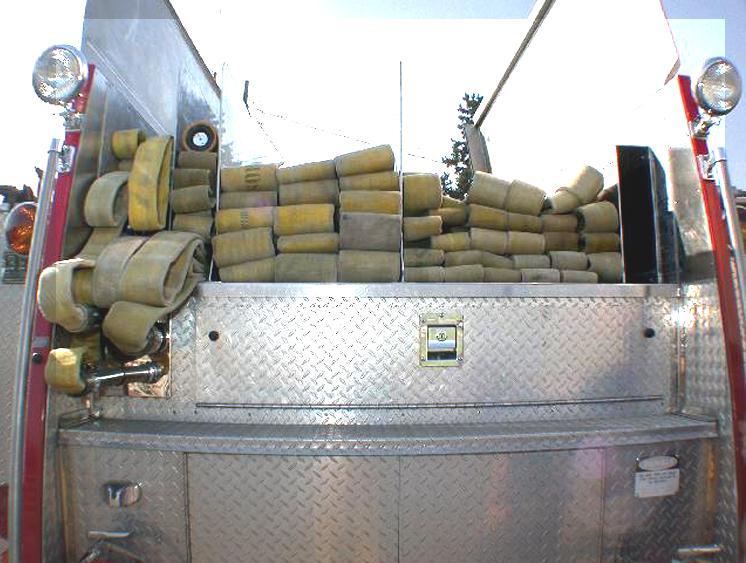
15 LOADING HOSE - FLAT A1.1 A AA Revised 7/11/
16 LOADING HOSE - REEL LINES A1.1 A AA 1. Lay out and connect sections of hose, install nozzle, and charge line with sufficient pressure to test for leaks and expel air from line. 2. Retain sufficient pressure in hose to promote hose expansion. Wind hose on reel. 3. When one layer is completed, the next layer is laid in opposite direction until reel is loaded. 4. Crack nozzle to relieve pressure in hose. Secure nozzle. Revised 7/11/


17 LOADING HOSE - REEL LINES A1.1 A AA Revised 7/11/
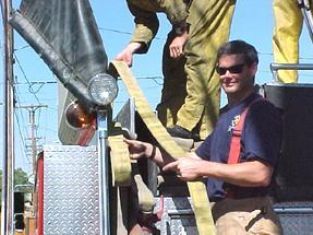
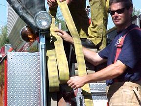
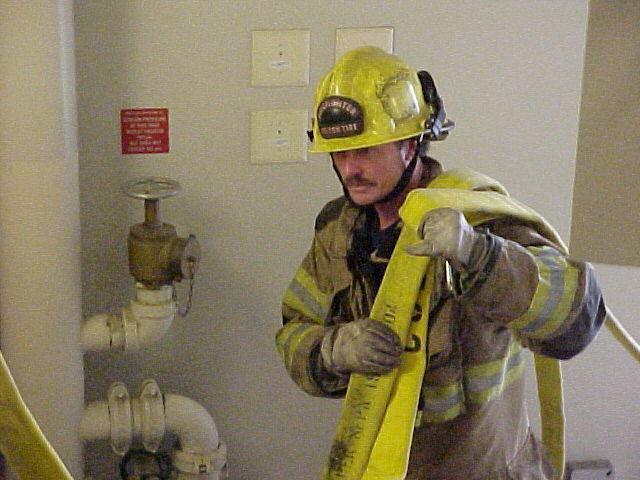
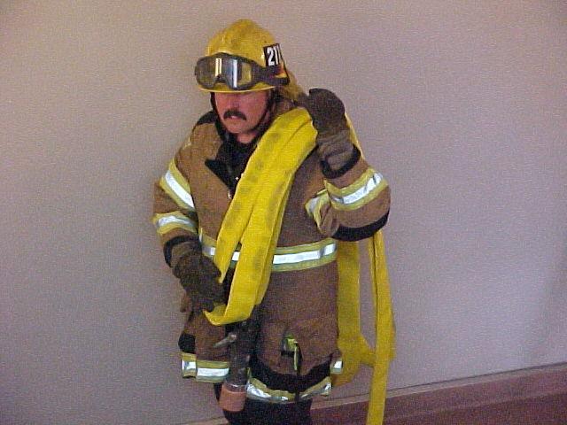
18 HOUSE BUNDLES/HIGHRISE PACK A1.1 A AA 1. Obtain two 50 sections of 1 ¾ hose, nozzle and gated wye. 2. Connect nozzle to a male coupling and lay nozzle down. 3. Make folds in hose that are 5 long, with the first return fold going through the nozzle bale (Fig. 1). 4. Continue folds until entire 100 is used. 5. Secure bundle tight by using Highrise straps (Fig. 2) 6. Attach gated wye to female coupling. 7. Load the bundles onto the truck with the nozzle down and against the hose bed. 8. You should be able to reach the nozzle without standing on the tailboard and reaching very far into the hose bed. Note: Bundles can be loaded onto the firefighter via the Over the shoulder method OR being placed over the S.C.B.A. cylinder. Revised 7/11/

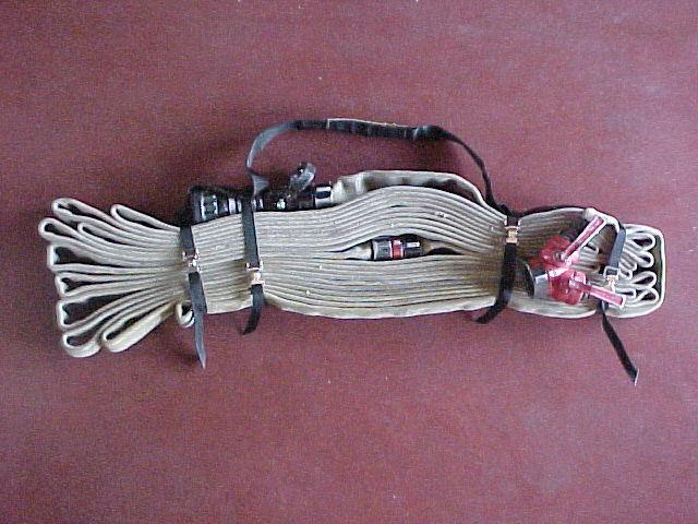
19 HOUSE BUNDLES/HIGHRISE PACK A1.1 A AA Revised 7/11/
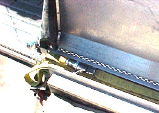
20 HOSE LOAD TRANSVERSE A1.1 A AA The Colton Fire Department currently has either rear mounted, transverse pre-connects or both, on all first out apparatus. The transverse pre-connects will carry 200 of 1 ¾ hose. This is the procedure for loading the transverse pre-connects. 1. Place 200 of 1 ¾ hose, connected, to the side of the apparatus. 2. Record appropriate hose numbers in hose record kept in apparatus. 3. Connect female hose coupling to male fitting inside hose bed. 4. Start loading hose into bed, either side, and continue feeding hose in until the first coupling is in the bed (50 ). 5. Make a loop 12 to 18 beyond the hose bed on the left side. (Fig. 2) 6. Continue feeding hose, making folds next to each other, until 150 of hose has been loaded. 7. Prepare a loop as in Step 5, and place on the right side of the hose bed. (Fig 3) 8. Continue remaining hose into bed. 9. Place nozzle on male end coupling and lay on top of hose when attached. (Fig. 4) Revised 7/11/
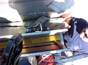

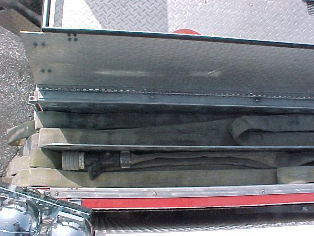
21 HOSE LOAD TRANSVERSE A1.1 A AA 10. Fig. 2 Fig. 3 Fig. 4 Revised 7/11/
22 HOSE LOAD REAR PRECONNECT A1.1 A AA To effectively attack and extinguish a fire, hose lines must be removed from the apparatus and advanced to the location to the fire. Advancing the pre-connected flat load involves pulling the hose from the compartment and walking toward the fire. Proper loading of the hose prior to usage insures that the removal and advancement will effectively be accomplished. 1. Lay out 150 of 1 ¾ of hose at rear of apparatus. Load bottom first. 2. Record appropriate hose numbers in hose record kept in apparatus. 3. Connect hose to 1 ½ gated wye. 4. Start loading hose into bed, and continue feeding hose in until the first coupling is in bed (50 ). 5. Make a loop beyond the hose bed on the left side. 6. Continue feeding hose, making folds next to each other, until 100 feet of hose has been loaded. 7. Make second loop at beginning of third section. Make loop in length and position it at right side of hose bed. 8. Continue loading remaining hose into bed. 9. Connect nozzle and place at rear of hose bed. Nozzle tip pointing out. 10. Replace rack for upper bed. 11. Connect first section of upper bed. Load hose in the same manner used in lower section loading. Revised 7/11/

23 HOSE LOAD REAR PRECONNECT A1.1 A AA Revised 7/11/
24 A1.1 A AA Intentionally left bland Revised 7/11/
25 A1.1 A AA Intentionally left blank Revised 7/11/
26 HOSE LOAD 2-1/2' QUICK ATTACK A1.1 A AA The Colton Fire Department has adopted and implemented the use of 150 of pre-loaded and prenozzled 2 ½ attack hose on all Colton Pumper units. The Quick Attack hose uses 150 of 2 ½ pre-nozzled with a 300 gpm nozzle. This is the procedure to follow when loading the Colton 2 ½ Quick Attack Line. Procedure: 1. Place 150 of 2 ½ hose at the rear of Colton Pumper. 2. Record appropriate hose numbers into the hose record kept in apparatus. 3. Place female end of hose to the front of hose bed or connect to 2 ½ discharge. 4. Proceed with traditional flat loading of hose until approximately 75 is loaded. 5. Place a grab loop of approximately in the middle of the second 50 length of hose. Continue to load remainder of hose. 6. Nozzle the male coupling at the end of 150 of 2 ½ hose with 300 gpm select-o-mate nozzle. Important Points: 1. Initial female coupling placed at front of hose bed or connected to a 2 ½ discharge. 2. Grab Loop of appropriate length in middle of 2 nd length of hose. 3. All couplings are tight. 4. Last male coupling is nozzled with a select-o-mate nozzle. Revised 7/11/


27 HOSE LOAD 2-1/2' QUICK ATTACK A1.1 A AA Revised 7/11/
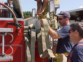
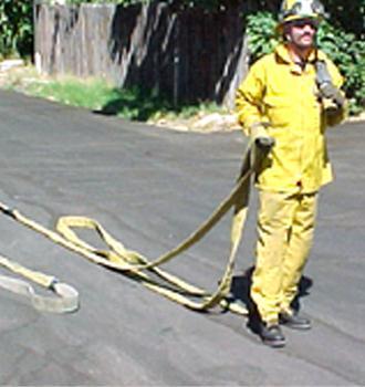
28 PREPARING SHOULDER PACKS A1.1 A AA 1. With nozzle installed on line leading from hose bed, the nozzle person positions them self with their back to the apparatus, six feet from the tailboard. Place nozzle over right shoulder toward the front of the body. Engineer positions himself between the nozzle person and the tailboard. 2. Engineer forms shoulder pack on nozzle person, the first loop formed to the rear, hanging between hip and knee. 3. When the nozzle person has approximately 50 feet of hose folded on their shoulder, step away from tailboard allowing 15 feet clearance. The next person positions them self 6 feet from the tailboard, placing the line leading from hose bed to nozzle person over their shoulder. 4. Engineer forms shoulder pack on second mans shoulder, the first loop to the rear, hanging between hip and knee. When second man is loading he steps away from the tailboard approximately 15 feet. 5. Engineer continues to load additional personnel following steps 3 and 4 until adequate hose is obtained. NOTE: When shoulder packs are used in conjunction with straight lay evolutions or with standpipe, the engineer breaks the coupling at the hose bed when the last man is fully loaded and installs a double female on the pack. If necessary on reverse lays, after the last man is loaded, engineer makes adequate pulls to reach entrance of structure, installs hose clamp, lays line to water source. Revised 7/11/


29 PREPARING SHOULDER PACKS A1.1 A AA Revised 7/11/
30 FOLD, PACK AND CARRY A1.1 A AA 1. Pull required amount of hose from bed (straight or reverse lay). 2. Spread couplings apart (if possible) at 25 behind engine. 3. Nozzle hoseline and place nozzle in line with other couplings. 4. Grasp hose at fold opposite couplings and advance to couplings. 5. Grasp both newly formed folds and repeat step #4. 6. Kneel on nozzle side of bundle and gather folds together neatly. ** NOTE: For each succeeding length of hose, the coupling is treated as the nozzle. 7. Place bundle on shoulder (right or left as ordered by the nozzle person). 8. Advance line. Revised 7/11/


31 FOLD, PACK AND CARRY A1.1 A AA Revised 7/11/
32 DOUBLE DONUT - 2 PERSON A1.1 A AA 1. Prepare hose for rolling A section folded back upon itself B. #1 man sets male coupling 2 to 3 feet on top of hose, behind female coupling C. #2 man pulls excess hose back D. #1 man walks towards fold straightening hose along the way 2. Prepare to roll hose A. #2 man grasps hose at fold B. #2 man starts roll by making hand hold C. Fold hose back on itself (4 to 6 inches) 3. Roll Hose A. #2 man rolls hose towards coupling B. #1 man straddles hose with back towards couplings C. While #2 man is rolling, #1 man walks backwards assuring that hose is straight and to keep the hose from buckling D. #1 man feeds top layer of hose into roll E. Roll hose to male coupling 4. Secure Hose A. #1 man grasps female coupling and checks for gasket B. #1 man hands female to #2 man C. Roll remaining hose over male coupling 5. Flatten Roll A. Lay roll on its side B. Stand on roll to flatten Revised 7/11/


33 DOUBLE DONUT - 2 PERSON A1.1 A AA Revised 7/11/
34 DOUBLE DONUT - 1 PERSON A2.8 A AA 1. Lay Hose Out A. Straight and flat B. 50 section 2. Bring Male end of Hose Back to Female End A. Hose laid side by side B. Couplings even 3. Prepare to Roll Hose A. Stand at fold of hose 4. Grasp Hose A. 2 to 3 feet towards male coupling B. Fold hose on itself 4 to 6 inches (hand hold) 5. Roll Hose A. Toward male coupling B. All the way to male coupling 6. Secure Hose A. Wrap excess hose around roll and coupling B. Check for gasket 7. Flatten Roll A. By standing on side of roll Revised 7/11/


35 DOUBLE DONUT - 1 PERSON A2.8 A AA Revised 7/11/
36 RETURN TO QUARTERS ROLL A1.2 A AA 1. Lay out hose a. Straight and Flat, 1 section 2. Stand at male end a. Facing length of hose 3. Grasp male end 4. Lay coupling back on hose a. 4 to 6 b. Male coupling perpendicular to hose c. Make hand hold for carrying d. Male coupling will be inside of roll to protect threads. 5. Roll Hose a. Towards female coupling 6. Flatten Roll a. Lay roll on its side b. Stand on roll to flatten Revised 7/11/


37 RETURN TO QUARTERS ROLL A1.2 A AA Revised 7/11/
38 MAKING HYDRANT (4" SUPPLY) A1.2 A AA 1. Grasp 4 hose and hydrant wrench. 2. Step off tailboard, and walk back approximately Wrap hose ½ turn around the hydrant. 4. Snub line and signal loudly for the engineer to proceed. 5. Connect hose to the 4 outlet. a. On hydrants without a 4 outlet, use the reducer to connect to a 2 ½ outlet. b. Clear hydrant. 6. When the engineer signals with two blasts from the air horn, charge the hydrant, opening the valve slowly to prevent water hammer. 7. Report to the Captain. Revised 7/11/

")


39 MAKING HYDRANT (4" SUPPLY) A1.2 A AA Revised 7/11/
40 ANCHORING HOSE A1.2 A AA 1. Grasp hose about 15 feet behind tailboard. 2. Hold hose with both hands. 3. Stand to side of hose with feet spread. 4. Signal engineer to proceed with a loud vocal signal. Revised 7/11/

41 ANCHORING HOSE A1.2 A AA Revised 7/11/
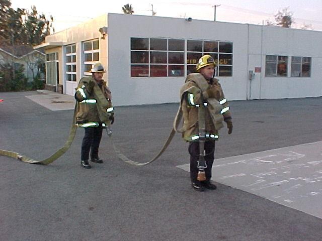
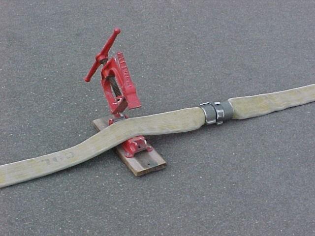
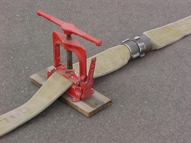
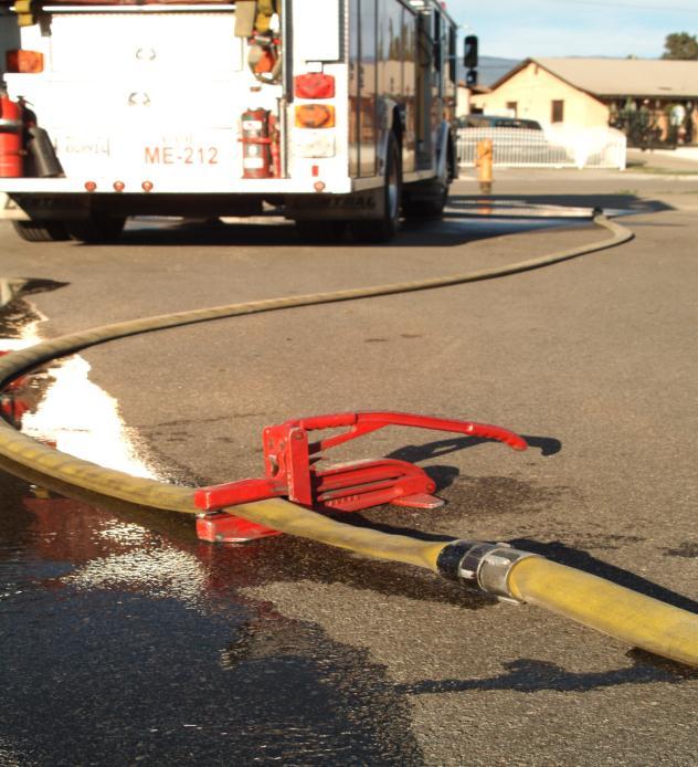
42 INSTALLING HOSE CLAMPS A1.2 A AA 1. Place at sufficient distance from apparatus to avoid any interference with unloading adequate hose. 2. On cotton and polyester jacket hose, install within eighteen inches of the coupling on the water source side with handle opposite the side the hose pulls are to be made. 3. For rubber hose install adjacent to coupling on the water source side with handle opposite the side the hose pulls are to be made. Note: The hose clamp should be used in conjunction with laying hose lines to insure the shutting off of water and to allow ample time to place uncharged hose lines into position for use on the fire. It should always be available for use on broken hose lines and in other emergencies. It may be used for shutting off flow of water to bleed lines to take above ground. Revised 7/11/
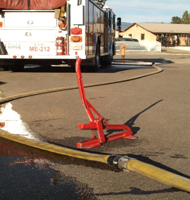
43 INSTALLING HOSE CLAMPS A1.2 A AA Revised 7/11/
44 UNCOUPLING HOSE A1.1 A AA Foot Method FIG Step on hose directly behind female coupling. 2. Lift up with left hand to clear coupling off the ground. 3. Disconnect coupling, turning female swivel clockwise. Straddle Method FIG Straddle hose behind male coupling. 2. Place hose between the knees. 3. Disconnect couplings. a. Turning female swivel clockwise. 4. Lay couplings DOWN GENTLY. Revised 7/11/


45 UNCOUPLING HOSE A1.1 A AA 5. Fig. 1 Fig. 2 Revised 7/11/
46 COUPLING HOSE A1.4 A AA Foot Method 1. Step on hose directly behind male coupling. a. Use hard surface only. 2. Pick up female coupling with fingers inserted inside coupling to check for gasket. 3. Place female against male and reverse to set threads. 4. Connect couplings. a. Turn clockwise. b. Align flat part of hose before making hand tight. Straddle Method 1. Straddle hose behind female coupling. 2. Pick up female coupling with fingers inserted inside coupling to check for gasket. 3. Place hose between the knees. 4. Pick up male coupling. 5. Place male against female and reverse to set threads. 6. Connect couplings. a. Turn clockwise. b. Align flat part of hose before making hand tight. Revised 7/11/


47 COUPLING HOSE A1.4 A AA c. Fig. 1 Fig. 2 Revised 7/11/
48 COUPLING AND UNCOUPLING HOSE (FORESTRY METHOD) A1.4 A AA This method of coupling or uncoupling hose can be used when working with small diameter hose (1 ¾ and smaller). 1. Grasp each coupling. a. Female right hand. b. Male left hand. 2. Hold at a comfortable level. 3. Place each coupling together and tighten using the fingers of both hands. 4. Reverse the process when uncoupling. Revised 7/11/


49 COUPLING AND UNCOUPLING HOSE (FORESTRY METHOD) A1.4 A AA Revised 7/11/
50 INSTALLING NOZZLE A1.5 A AA FIGURE 1 - INSTALLING NOZZLE 1. Step on hose, just behind male coupling. 2. Grasp nozzle at base of tip with left hand. 3. With right hand line up threads and INSTALL NOZZLE. FIGURE 2 LEADING IN HOSE LINES 1. Place hose over shoulder, nozzle to the front. 2. Grasp nozzle with left hand, secure hose with right hand, and LEAD IN. 3. Continue to LEAD IN - OPERATE NOZZLE. Revised 7/11/


51 INSTALLING NOZZLE A1.5 A AA Fig. 1 Fig. 2 Revised 7/11/
52 2 1/2" HAND LINE - ONE MAN A1.5 A AA 1. Grasp nozzle and loop hose back towards working line. 2. Pass nozzle underneath hose. a. 15 to 20 from nozzle. b. Nozzle will rest on ground. c. Assure that hose passes straight back from nozzle (about 6 ). 3. Anchor hose. a. Sit on hose where working line crosses behind nozzle. 4. Grasp handles and operate nozzle. Revised 7/11/


53 2 1/2" HAND LINE - ONE MAN A1.5 A AA 5. Revised 7/11/
54 2 1/2" HAND LINE - TWO MAN A1.5 A AA 1. Place hose strap on hose. a. Behind coupling at nozzle. b. Nozzleman should be facing working line (back to nozzle). 2. Place hose strap on shoulder that is closest to working line. 3. Second man on opposite side of hose as first. a. 6 to 8 back from nozzleman. b. Place hose strap on hose facing working line with back to nozzle. 4. Second man puts hose strap on shoulder that is closest to working line. 5. Both men stand and pivot towards the hose so they are facing the nozzle. a. IMPORTANT: HOSE STRAP WILL CROSS-CHEST. 6. Nozzleman will operate nozzle. 7. Back-up man will move hose at nozzleman s direction. Revised 7/11/


55 2 1/2" HAND LINE - TWO MAN A1.5 A AA Revised 7/11/
56 A1.7 A AA Intentionally Left Blank Revised 7/11/
57 A1.7 A AA Intentionally Left Blank Revised 7/11/
58 A1.7 A AA Revised 7/11/
59 CARRYING HAND TOOLS A1.8 A AA 1. Carry tools at side of body. a. Point or blade down. b. Head forward. 2. At balance point. 3. Downhill side. 4. Important points: a. Do not suddenly swing around. b. Work or walk 10 to 15 feet apart. c. Sound off if passing another worker. d. Maintain good footing when working. e. Remember your anchor point. f. Work as a team. g. Post a lookout. h. Rotate crews. Revised 7/11/

60 CARRYING HAND TOOLS A1.8 A AA Revised 7/11/
61 HOSE COUPLINGS A1.9 A AA COUPLING INDENTIFICATION Lugs are provided on couplings so that a grip can be obtained with spanner wrenches to assist in tightening and breaking couplings. Most hose purchased today comes equipped with rocker lugs, to help the coupling slide over obstruction when the hose is moved on the ground or around objects. Most booster lines have the recessed couplings to prevent them from getting hung up. Revised 7/11/


62 HOSE COUPLINGS A1.9 A AA Rocker Lug Recessed Revised 7/11/
63 HOW TO PULL 1 3/4" PRECONNECTED LINES A2.3 A AA 1. Hoseman goes to either the side or rear of the pumper. 2. With left hand, he picks up the nozzle and drapes it over his left shoulder (don t let go of the nozzle). 3. Facing away from the pumper, insert right arm through both loops, top loop first, bottom loop last. 4. First loop should rest on upper arm and second loop should be in your right hand. 5. Pull on both loops while stepping off the pumper, pull clear of pumper. 6. Proceed toward fire, at approximately 50 you will feel resistance on the loop you are holding in your right hand, at this point let it drop. Continue toward fire, drop remaining loop when resisting is felt again. 7. Lead nozzle into fire area. Revised 7/11/


64 HOW TO PULL 1 3/4" PRECONNECTED LINES A2.3 A AA 8. Revised 7/11/
65 HOW TO EXTEND 1 3/4" PRECONNECTED LINES A2.3 A AA A. First hoseman: 1. First hoseman goes to the rear of the pumper, disconnects the top pre-connect from gated wye. 2. Steps up on the tailboard, and picks up the nozzle and female coupling in left hand. 3. Facing away from the pumper, he inserts right arm through both loops of the top preconnect. First loop should rest on your upper arm; second loop should be in your right hand. 4. Pull on both loops while stepping off the tailboard. 5. Dragging hose, proceed to transverse pre-connect bed. B. Second hoseperson: 1. Second hoseperson removes nozzles from either transverse pre-connect and secures same. 2. First hoseman hands female coupling to second hoseman, who connects female to male coupling of hose where nozzle was removed. Hold connection in left hand. 3. Second hoseman inserts right arm through both loops, first loop should rest on your upper arm; second loop should be in your right hand. 4. Pull on both loops to remove hose from bed. 5. First hoseman leads toward the fire with second hoseman following, (keeping clear of hose). 6. When second hoseman s hose is depleted, he notifies the first hoseman by shouting out. 7. First hoseman continues until hose is fully extended or destination is reached. 8. Stand firm and open nozzle slowly. Revised 7/11/


66 HOW TO EXTEND 1 3/4" PRECONNECTED LINES A2.3 A AA Revised 7/11/
67 WYE - ONE LINE INTO TWO A2.3 A AA 1. Lay out desired amount of hose for two lines. 2. Unload wye and one nozzle. 3. Install nozzle on one line. 4. Connect both hose lines to wye. 5. Signal engineer to shut down line if already in operation. 6. Remove nozzle and attach wye. 7. Install nozzle on second line. 8. Lead in both lines from the wye and signal engineer to charge the line. Revised 7/11/

68 WYE - ONE LINE INTO TWO A2.3 A AA Revised 7/11/
69 SIAMESE - TWO LINES INTO ONE A2.3 A AA 1. Lay two lines or use lines previously laid. 2. Obtain one siamese and a nozzle from the pumper and place on the tailboard. 3. Obtain single line and make a fold pack and carry. 4. Connect nozzle and siamese to single line. 5. Connect female ends of siamese to male ends of dual lines. 6. Take nozzle to desire location. 7. Signal the engineer to charge lines Revised 7/11/

70 SIAMESE - TWO LINES INTO ONE A2.3 A AA Revised 7/11/
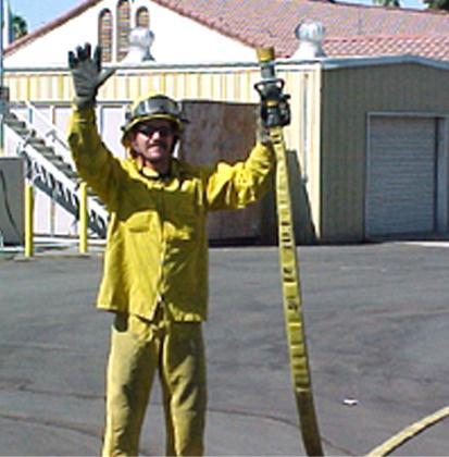
71 HOSE LAY EVOLUTIONS - HAND SIGNALS / DUALS AND SINGLE LINES A2.3 A AA APPENDIX I HAND SIGNALS The following signals shall be used as the departmental standard for all hose evolutions and fire ground operations. FIGURE 1 CHARGE LINE Raise both arms vertically above head, palms outstretched toward direction to which you are signaling; holding them stationary until signal is acknowledged in same manner. FIGURE 2 SHUT DOWN LINE Extend both arms downward at an angle of 45 degrees, crossing them in front of the body. Swing them back and forth. FIGURE 3 INCREASE PRESSURE Extend arms horizontally from shoulders (palms up) moving them up and down from horizontal to 45 degrees. FIGURE 4 DECREASE PRESSURE Extend arms horizontally from shoulders (palms down) lowering and raising them from horizontal to 45 degrees. Revised 7/11/


72 HOSE LAY EVOLUTIONS - HAND SIGNALS / DUALS AND SINGLE LINES A2.3 A AA Fig. 1 Fig. 2 Fig. 3 Fig. 4 Revised 7/11/
73 HOW TO PULL 2-1/2" WORKING LINE A2.4 A AA 1. Grasp hose coupling and proceed away from apparatus until next coupling clears tailboard. 2. Place coupling on ground and return to rear of pumper. 3. Pick up next coupling and proceed away from apparatus and place next to the other coupling. 4. Repeat until required hose has been unloaded. 5. Unload nozzle. (If performing a reverse lay, anchor hose and send engine to hydrant.) 6. Nozzle hose and lead into fire. Note: First pull is closest to fire and succeeding pulls are away from fire. Revised 7/11/


74 A2.6 A AA Retrieve a nozzle. If performing a reverse lay then anchor the hose and send the engineer to hydrant. Revised 7/11/
75 RAILROAD LAY (2-1/2" AND 4" HOSE) A2.6 A AA 1. Captain orders Railroad Lay, 2 ½ or 4 lines. 2. If pulling 2 ½ hose for a working line, first man installs nozzle. 3. If pulling a 4 supply line back to hydrant, first man grasps coupling and leads out. 4. Second man grasps next coupling and follows first man. 5. Manpower permitting, third and fourth man grasps succeeding couplings. Revised 7/11/


76 RAILROAD LAY (2-1/2" AND 4" HOSE) A2.6 A AA Revised 7/11/
77 HOSE BUNDLES 2-1/2" TO 1-3/4" A2.8 A AA 1. Disconnect bottom pre-connect from wye. 2. Disconnect wye from rear discharge. 3. Pull the top rear pre-connect half way out of the bed. 4. Facing away from the pumper, load top rear pre-connect on right shoulder. a. Optional method is to pull the pre-connect out using loops in the normal manner. 5. Hold the wye and nozzle in either hand. 6. Carry the 1 ¾ hose to the desired locations. 7. Attach wye to 2 ½ line. a. Insure that second outlet on wye is closed. 8. Signal engineer to charge 2 ½ line. 9. Charge 1 ¾ hose line and lead in. 10. Additional personnel will obtain second rear pre-connect in the same manner. Revised 7/11/


78 HOSE BUNDLES 2-1/2" TO 1-3/4" A2.8 A AA Revised 7/11/
79 REPLACING A BROKEN LENGTH OF CHARGED LINE A2.8 A AA 1. If line has not been shut down, it may be necessary to take a hose clamp. 2. Obtain two lengths of hose, of the same diameter from the apparatus and make a fold pack and carry, shoulder pack or any other approved method. 3. Place hose clamp 51 back from the section of hose being replaced and if needed notify nozzle person of water being shut down. 4. Advance to ruptured section and replace broken section with replacement hose. 5. If needed, notify nozzle person of water coming and release hose clamp or signal engineer to charge line. NOTE: It takes two sections of hose to replace one broken section. Revised 7/11/


80 REPLACING A BROKEN LENGTH OF CHARGED LINE A2.8 A AA Revised 7/11/
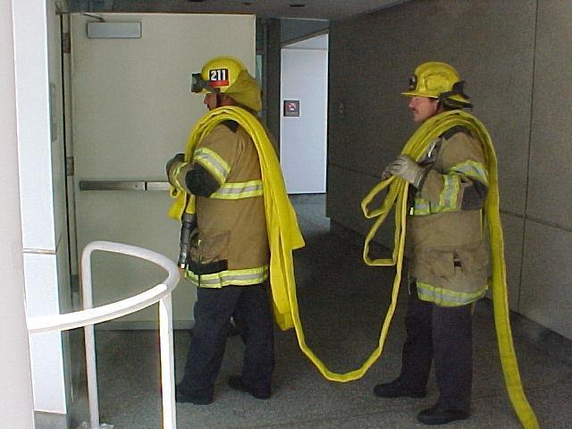
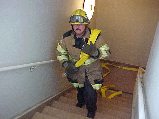
81 HOSE TECHNIQUES / HOSE BASIC SKILLS A2.9 A AA Lines Above Ground Line Placement Up Stairways 1. Personnel proceed up the stairs, nozzleman leading, other personnel maintaining tenfoot spacing. 2. Last man to enter structure pays off his shoulder pack first, dropping one fold at a time using the right hand to control the pack. 3. Each man, in sequence, working from base to top of stairs, pays off his shoulder pack, secures hose and assists nozzleperson. Revised 7/11/
82 HOSE TECHNIQUES / HOSE BASIC SKILLS A2.9 A AA 4. Revised 7/11/
83 LINES ABOVE GROUND (LINE UP LADDER) A2.9 A AA 1. Place adequate hose at the base of the ladder. 2. Nozzleman places hose over shoulder with nozzle on back and hose trailing to opposite side of body. 3. Assisting men place hose strap on hose at approximately 25 intervals with couplings ahead of hose strap. 4. Nozzleman begins climbing. 5. Assisting men thread arm through the hose strap and place on shoulder, keeping all hose to the same side of ladder. 6. Assisting men begin climbing, maintaining a 10 to 15 interval. 7. After reaching desired floor, nozzleman lays nozzle down and turns to ladder for slack hose. 8. Men lock in on ladder and pass hose to nozzleman. 9. Nozzleman signals when he has sufficient hose and all men secure hose to ladder using hose strap. Nozzleman secures hose to the ladder at the top. 10. Required number of men proceeds up the ladder and assist the nozzleman advance the hose line. Revised 7/11/


84 LINES ABOVE GROUND (LINE UP LADDER) A2.9 A AA Revised 7/11/
85 LINES ABOVE GROUND - LINE PLACEMENT / PIKE POLE TECHNIQUE A2.9 A AA 1. Place adequate hose below balcony. 2. If necessary, raise ladder to first floor balcony; secure ladder. 3. Personnel climb ladder, positioning one man on each landing, and one man remaining on ground. 4. Man on ground secures nozzle to top of pike pole with hose strap (Fig. 1), passes butt of pole to man on first landing. 5. Personnel pass pike pole to each other and assist in pulling hose. (Fig. 2) 6. When adequate hose has reached the fire floor, personnel secure hose. 7. Personnel assist nozzleperson. Revised 7/11/


86 LINES ABOVE GROUND - LINE PLACEMENT / PIKE POLE TECHNIQUE A2.9 A AA Fig. 1 Fig. 2 Revised 7/11/
87 LINE ABOVE GROUND (INTERIOR) A2.9 A AA Lines Above Ground Determining Hose Requirements For Shoulder Packs 1. OPEN STAIRWAYS: The hose may be hung in the well provided it is supported and secured with hose straps. To estimate the amount of hose needed for shoulder packs: a. Determine footage of hose necessary to reach from the point that pack will be connected to a standard hose lay (normally the entrance to the structure) to the base of the stairs. b. Add 15 per floor (or one section of hose for every three stories). c. Estimate the distance from the point of entry on the fire floor to the furthest point of the fire. 2. CLOSED STAIRWAYS: The hose is to be placed on the stairs against the outside walls to allow safe ingress and egress. To estimate the amount of hose needed for shoulder packs: a. Determine footage of hose necessary to reach from the point the pack will be connected to a standard hose lay at the base of the stairs. b. Add 25 for each floor (one section of hose per two stories). c. Estimate the distance from the point of entry on the fire floor to the furthest point of the fire. Revised 7/11/

88 LINE ABOVE GROUND (INTERIOR) A2.9 A AA Revised 7/11/
89 CONNECTING TO PROTABLE MONITORS A2.10 A AA 1. Lay two (2) or more 2 ½ lines. 2. Remove monitor and base plate from engine. 3. Set up monitor. 4. Crisscross lines at rear of monitor and loop around to front outlets. Strap 2-1/2 lines if necessary. NOTE: On newer monitor bases with female coupling at rear of base, lay lines straight into monitor. Revised 7/11/


90 CONNECTING TO PROTABLE MONITORS A2.10 A AA Revised 7/11/
91 CONNECTING TO SPRINKLER OR STANDPIPE SYSTEMS A2.11 A AA Figures 1 and 2 1. Lay one or more lines to inlet manifold connections. 2. Remove plugs or caps from inlets. Check inlets for gaskets and for foreign materials. 3. Connect hose lines to inlets. 4. Charges hose lines. Note: On system with inlets in a horizontal position, connect to the center inlets first. On systems with inlets in a vertical position, connect to the lower inlets first. Figures 3 and 4 CONNECTING TO INTERIOR AND EXTERIOR STANDPIPES 1. Carry hose, nozzle and necessary fittings to desired floor. 2. Connect stinger to standpipe outlet. 3. Connect female couplings of hose to stinger. Secure with hose straps if required. 4. Open standpipe outlet. 5. LEAD IN; OPERATE NOZZLE. Revised 7/11/
92 CONNECTING TO SPRINKLER OR STANDPIPE SYSTEMS A2.11 A AA Revised 7/11/
93 PROGRESSIVE HOSE LAY A3.1 A AA 1. Locate apparatus for best advantage. 2. First man puts on a hose pack and pulls desired amount of 1 ½ working line from flat load and leads out. Engineer connects line to discharge. 3. Second man dons hose pack and assists nozzleman in advancing hose line until new section of hose is needed. 4. Second man or third man, if available, removes new length of hose from nozzleman s hose pack and unrolls it. 5. Shut off nozzle. 6. Clamp or kink hose. 7. Open nozzle to relieve pressure, then remove nozzle. 8. Connect new section of hose to the lay. 9. Connect nozzle to new section of hoe. 10. Make sure new section of hose is free of kinks and out of burn. 11. Remove clamp or kink to charge line. 12. Continue extinguishments until new section of hose is needed and repeat procedure. Note: 1. Leave nozzle cracked when clamping hose. 2. Unroll hose down hill; avoid getting tangled. 3. Do not advance hose line until you have water at the nozzle. Revised 7/11/
94 A3.1 A AA This page intentionally left blank Revised 7/11/
95 A3.1 A AA This page intentionally left blank Revised 7/11/
96 DESCRIPTION OF RESCUE ROPES B 2.1 B BB Rescue Rope Rescue rope is used for a variety of purposes in technical rescue. It is the primary tool for raising and lowering rescuers, equipment and victims. It is used to protect rescuers and victims as they move and work in elevated positions where a fall could cause injury or death. It is also used to create pulley systems. All rescue rope used in the Colton Fire Department is ½ (12.7mm) diameter, low stretch kernmantle rope. By today s manufacturing standards, ½ (12.7mm) rescue rope meets or exceeds the minimum safe working and breaking strengths. NFPA 1983 is the standard for life safety rope. Minimum breaking strength for rope used in two person systems shall not be less than 9000 lbs. (pounds force). There will be a 15:1 safety margin. All Rescue Systems 1 systems require two ½ NFPA certified ropes. An extreme rescue load is given as 600 lbf. about the weight of two fully equipped rescuers. A 9000 lbf. breaking strength rope with a 600 lbf. load provides a 15:1 safety margin. NFPA 1500 (1997) states: life safety rope may be reused if inspected and no impact load, damage, or exposure to any chemical material known to deteriorate rope has occurred. Rescue Rope Construction- Low stretch (static) ropes are the preferred types of rope for rescue work. They stretch very little when loaded, less than 5% at 450 lbf. (pounds force) with a minimum elongation of not less than 75% of breaking strength, and a maximum elongation of not more than 75% of breaking strength (NFPA 1983, 1995 edition). Low stretch (static) rescue rope is constructed using a kernmantle design. Kernmantle is a German word meaning core and sheath. The kern, or core, is made up of continuous parallel fibers running the length of the rope. This is known as block creel construction. The core carries the majority of the load, or about 75%-90% of the rope s strength, and is protected by the mantle or sheath. The sheath is a tight weave of nylon that carries the remainder of the load. By it s design, low stretch (static) rope has a thicker sheath that protects it from abrasion damage. The sheath also protects the core from abrasion, dirt, and the effects of sunlight, which can weaken nylon with prolonged exposure. 97
97 ROPES: INSPECTION, CLEANING, STRENGTH, MARKING B 2.1 B BB Inspection Visually inspect the rope for: Unusual wear Cuts Exposed core material Excess wear and abrasion of the sheath material Discoloration that could be from chemical contamination Burn marks from excessive friction and heat buildup Feel the rope as it is being stuffed into the rope bag for: Soft spots Kinks Unusual bulges Inconsistent texture and flexibility Unequal diameter or thickness Excess contamination from dirt or debris Any of these could indicate damage to the core of the rope, and may require taking a rope out of service. If in doubt, take the rope out of service. Cleaning Keep ropes clean of mud and dirt, which can act as a sharp abrasive if allowed to work its way into the core of the rope Wash rope with hose washer hooked to garden hose Wash with cold water Never use detergents, as they may cause damage to the rope To avoid mildew and mold, make sure the rope is completely air dried before storing in a rope bag Do not dry rope in direct sunlight 98
98 ROPES: INSPECTION, CLEANING, STRENGTH, MARKING B 2.2 B BB Strength Marking Bending rope fibers reduce the strength of a rope. Any knot will reduce the strength of the rope. Whenever a rope is placed under a load with a sharp bend in it, there is a strength loss. The larger the diameter of the bend, the less strength loss to the rope. Tests have shown that there is not a significant loss of strength until nylon rope is bent to less than four times the diameter of the rope. For a ½ (12.7mm) rope, the minimum bend should be 2 to maintain the maximum strength. Rescue rope should be marked or tagged, so that the history of each individual rope can be maintained. Each rope should have a number on both its ends. The rope bag should have a card, which reveals the history of each rope. After a rope has been used and inspected the card should be punched in accordance in which way the rope was used. 99
99 RESCUE HARDWARE B 2.2 B BB RESCUE HARDWARE Webbing Webbing is used extensively in rescue work to build anchor systems, create emergency harnesses, package and secure victims; and to lash rescue components together. Do to its very small diameter; webbing is a better material to use when snapping into carabiners because it is more efficient in retaining its strength. A 4000 lb rated webbing loses very little of its strength when bent around a carabiner. Webbing is relatively inexpensive and can be cut into varied lengths for many uses. It is lightweight and easy to tie. Construction Nylon tubular webbing should be used in rescue applications. There are different methods of manufacture. Until the year 2000, the preferred method of construction was spiral weave/ shuttle loom. Although this type of construction is still safe to use, it is being replaced with needle loom construction, which is flat webbing that is folded and stitched together on one side. Webbing comes in several sizes. The 1 size used by the Colton Fire Department has a 4000 lb. breaking strength. Color-Coding Webbing is available in a variety of colors. A system of color-coding webbing to determine length greatly aids in setting up rescue systems. If you know, for example, that all pieces of orange webbing are 20 in length, it is easy to select the proper piece of webbing to construct a specific anchor sling or to lash a victim into a stokes basket. Red 4 Yellow 12 Blue
100 RESCUE HARDWARE B 2.2 B BB Prusik Loops Prusik loops were originally designed to allow a climber to ascend a vertical rope. Prusiks have been adapted to rescue work and perform three important functions in rescue systems as hauling prusiks, braking prusiks, and ratchet prusiks. In a raising system, the hauling prusik grabs the rope and pulls it into motion as part of a mechanical advantage system. The ratchet prusik holds the rope while the mechanical advantage system is reset. In a belay system, the tandem braking prusiks grabs the belay line to prevent it from moving if there were a mainline failure thus providing safety for the rescuer/victim. The Colton Fire Department uses an 8 mm prusik cord for prusiks on ½ (12.7 mm) rope and are cut to 70 (1.79m) in length to create long prusiks and 57 (1.46m) in length to create short prusiks (these lengths are compatible with 2 prusik minding pulleys). Several of each size is needed in most rescue systems. Each length of 8 mm cord is tied into a continuous loop using a double overhand bend. Once tied, prusiks should remain tied. A single prusik attached to the ½ mainline with a three-wrap prusik hitch is used for a hauling and ratchet prusik. A set of tandem prusiks, one long and one short, attached to the ½ belay line with three-wrap prusiks hitches, is used for a braking prusik. Tests by several different groups from different areas have shown the tandem prusik belay system to be the most effective means of protecting a rescue load. It was the only system tested that was consistently able to stop and hold rescue loads dropped from nominal heights without serious damage to the belay line. The tandem prusik belay is easy to set up, versatile, secure, and reliable. There are other mechanical devices on the market that can perform the same function as the prusik. However, these devices were designed to ascend vertical ropes only, not to catch a falling load. In slow pull tests, these devices have caused serious damage or severed rope at about 1/3 of the strength of the rope. Prusiks start to slip at about 1/3 of the rope s strength and then seize, warning of an overloaded system. Some rescuers are concerned about supporting a load with 8 mm rope, thinking that it is a weak link in the system. In fact, 8 mm prusiks are stronger than the mainline with a knot in it, attached, and bent around a carabiner. In all the testing done, prusiks have never failed at the bend of a carabiner. 101
101 RESCUE HARDWARE B 1.1 B BB Pick-Off Strap The pick-off strap is a section of 1 3/4 webbing used to connect the rescuer and victim together during a rescue to pick-off a victim who is stranded on the side of a building, rock face, or other slope. This strap is about 48 in length and has a D ring sewn on to one end. In the middle, a sliding buckle allows the rescuer to adjust the distance between the rescuer and the victim. The other end is folded over and sewn to ensure the buckle does not come undone during adjustment. Carabiners Carabiners, sometimes called snap links or crabs, are metal connectors that link the different components of a rescue system together. Carabiners are made of aluminum or steel. Rescue teams that carry their equipment long distances, such as mountain rescue teams, tend to use the lighter weight aluminum variety. Those rescue teams that are not as concerned about portability tend to use the stronger but heavier steel variety. Carabiners strength varies depending on the manufacturer. Aluminum carabiners have a breaking strength of from 6,000-8,450 pounds. Steel carabiners run between 9,000-13,000 pounds breaking strength. Locking carabiners are at full strength when the gate is closed and locked. A locking carabiner should not be unlocked and opened when under load. Carabiners are designed to be loaded end to end. They should never be sided loaded. 102
102 RESCUE HARDWARE B 1.1 B BB Rescue Pulleys In technical rope rescue, rescue pulleys are used to: Change direction of force on a running rope Reduce rope friction Create mechanical advantage Rescue pulleys are made of all metal for maximum strength. The sheave or the area that the rope runs on should be metal, and should be the proper width for the diameter of rope being used. Not only should it be wide enough, but also its diameter should be no less than four times the diameter of the rope for minimum loss of rope strength as the rope bends around the sheave. There are special pulleys manufactured to meet technical rope rescue requirements. Prusik minding pulleys are designed to work with prusiks to make a self-tending brake system for belay lines and ratchets for mechanical advantage pulley systems. Knot passing pulleys are designed to allow a knot to pass through. This is important when two lines need to be tied together in order to reach a victim. This pulley allows the knot to pass through the mechanical advantage system, which would not be possible with standard pulleys. Double sheave pulleys are valuable for setting up parallel systems and for increasing mechanical advantage. Figure Eight Descenders Figure eight descenders were designed as descending or rappelling devices. They work by creating friction when the rope is wrapped around them. The larger ring is the location where the rope passes through to create friction, and the smaller ring is for attaching to a harness or anchor. Rescue-eight descenders have an added feature called ears. These were added to prevent the rescue rope from accidentally forming a girth hitch and causing a jam that is difficult to fix. Rescue-eight descenders are easier to lock off and accept larger ropes. They are stronger and, because they are larger, they dissipate heat more quickly. For many years, figure eight descenders were used for breaking devices on lines belaying rescue (two person) loads. Drop tests have shown that figure eight descenders are inadequate for stopping a rescue load with as little as a one meter drop. Figure eight descenders should only be used for one-person rappels of limited distance, and for lowering one-person loads. 103
103 RESCUE HARDWARE B 1.1 B BB Brake Bar Rack Brake bar racks are friction devices, designed for use on the mainline, in lowering systems or for rappelling. Reeving the rope over and under the bars creates friction; the more bars used, the greater the friction. Adjusting the distance between the reeved bars along the rack, with maximum friction obtained by pushing the bars close together can also control friction. Four bars should be used when a single person load is on the line. The rope should also pass under the last bar used when rappelling to simplify tying off the rack, in mid-rappel, without losing friction. When reeving a brake bar rack, the rope should first contact the large (1 ) bar passing over the training groove. The rope should then pass under the next bar (with the straight slot) forcing the bar against the rack. The rope then passes over and under the rest of the bars. The training groove in the large bar and the straight slot in the second bar are provided to ensure that the rack is reeved properly. Mechanical Ascender (Gibb s) The mechanical ascender is a common ascender used in the fire service. All ascenders are designed for use in ascending a fixed rope. They may be used in rope rescue pulley systems as a ratchet cam or hauling cam. The potential force of the rope rescue system must not exceed the manufacturer s rated strength of the device. When using the mechanical ascender be sure that the pin is through both sides of the sleeve and locked before use. Do not use as a brake cam. Some tests have shown that when an ascender is used as a braking cam and is subjected to a significant shock load, the rope it is connected to has occasionally parted the sheath. 104
104 RESCUE HARDWARE B 1.1 B BB Anchor Plates Anchor plates are used to gather equipment. They are stamped from sheet aluminum (not cast) or stainless steel. The strength is per manufacturer. Edge Rollers Edge rollers are constructed of an aluminum frame and rollers. The frames may be connected together in series to provide protection on multiple sides. Edge Guard Edge guards may be constructed of canvas, rigid plastic or fire hose. Edge guards serve the same purpose as edge rollers in protecting rope over rough or sharp edges
105 KNOTS USED BY COLTON FIRE DEPARTMENT B2.3 B BB Five Considerations of Rescue Knots- - Ease with which knot is tied - Ease of identification and determination if they are tied correctly - Will not work loose on their own - Minimally reduce rope strength - Relatively easy to untie after loading (See corresponding figures on following pages) A. Running loop PAGE 107 B. Bight PAGE 107 C. Half hitch PAGE 108 D. Round turn PAGE 108 E. Slip knot PAGE 109 F. Square knot PAGE 109 G. Clove hitch PAGE 110 H. Becket bend PAGE 110 I. Leverage hitch PAGE 111 J. Bowline PAGE 111 K. Running bowline PAGE 112 L. Bowline on a bight PAGE 112 M. Bowline with a bight PAGE 113 N. Figure 8 stopper PAGE 114 O. Figure 8 on a bight PAGE 115 P. Figure 8 follow through PAGE 116 Q. Figure 8 bend PAGE 117 R. In-Line Figure 8 PAGE 118 S. Overhand PAGE 118 T. Overhand bend PAGE 119 U. Double overhand bend PAGE 119 V. Handcuff knot PAGE


106 KNOTS USED BY COLTON FIRE DEPARTMENT B2.3 B BB KNOTS A. Running Loop- Made by crossing one side of a bight over the standing part so that the rope crosses itself. B. Bight- Formed by simply bending the rope back on itself while keeping the sides parallel. 107


107 KNOTS USED BY COLTON FIRE DEPARTMENT B2.3 B BB KNOTS C. Half Hitch- Used to secure the working end of a rope or webbing. They usually follow a knot or round turn around an object. D. Round turn - One full round turn around an object or anchor. 108


108 KNOTS USED BY COLTON FIRE DEPARTMENT B2.3 B BB KNOTS E. Slip knot- An easily untied knot used to easily slip free. F. Square knot- Used to tie end of webbing on rescuer pelvic harness. 109


109 KNOTS USED BY COLTON FIRE DEPARTMENT B2.3 B BB G. Clove hitch- Used to secure the working end of a rope or webbing around an object. KNOTS H. Becket bend- Used to tie unequal diameter ropes together. 110


110 KNOTS USED BY COLTON FIRE DEPARTMENT B2.3 B BB KNOTS I. Leverage hitch- Used to tighten a rope between to anchor points. J. Bowline- Used to tie a bight at the end of a rope. 111


111 KNOTS USED BY COLTON FIRE DEPARTMENT B2.3 B BB KNOTS K. Running bowline- Used to tie the end of a rope to an object or piece of equipment for raising or lowering. L. Bowline on a bight- Used to form two bights at the end of a rope. 112

112 KNOTS USED BY COLTON FIRE DEPARTMENT B2.3 B BB KNOTS M. Bowline with a bight- Used to tie three bights at the end of a rope. 113

113 KNOTS USED BY COLTON FIRE DEPARTMENT B2.3 B BB N. Figure eight stopper knot KNOTS Uses: Stopper knot because it is used at the end of a rappel line to prevent rappelling past the end of the line Father of Family of Figure 8 s Figure 8 knots allow retention of 80%+ of the rated strength of the line they tie into. Figure 8 knots meet all four considerations of rescue knot s best. 114

114 KNOTS USED BY COLTON FIRE DEPARTMENT B2.3 B BB KNOTS O. Figure 8 on a bight- A figure eight on a bight is tied in the same manner as the stopper, but is tied with a bight in the rope to form a loop at one end. This is a secure loop for attaching the rope to anchors, equipment or rescuers. A tail at least 6 in length must be left at the end of the rope. 115

115 KNOTS USED BY COLTON FIRE DEPARTMENT B2.3 B BB KNOTS P. Figure 8 follow through- The figure eight follow through allows tying directly into or around an object. A figure eight stopper is tied and then the working end of the rope is passed around the object and follows the path made in forming the stopper back through the knot. The key to this knot is to leave enough length on the working end of the rope to pass around the object and complete the knot, leaving a 6 tail. The result is the same as the figure eight on a bight. 116

116 KNOTS USED BY COLTON FIRE DEPARTMENT B2.3 B BB KNOTS Q. Figure 8 on a bend- The figure eight bend is used to join the ends of one rope or the ends of two ropes of the same diameter together. A figure eight stopper knot is tied in the working end of the rope and left loose. The other end of the same rope or the working end of the other rope is passed through the figure eight stopper following the path used to form the stopper. Six-inch tails are left on the ends of the rope coming out of the knot. 117


117 KNOTS USED BY COLTON FIRE DEPARTMENT B2.3 B BB KNOTS R. In-line figure 8- The in-line figure eight is a directional knot that can be tied in the middle of a rope for attaching loads or for creating a trucker s hitch, which is useful for tensioning guy lines when building ladder gins and A frames. S. Overhand- Simple knot. 118


118 KNOTS USED BY COLTON FIRE DEPARTMENT B2.3 B BB KNOTS T. Overhand bend- Used to tie ends of webbing together to form a loop. U. Double overhand bend- Used to tie two ends of equal diameter rope together, such as used to tie a prusik loop. 119

119 KNOTS USED BY COLTON FIRE DEPARTMENT B2.3 B BB KNOTS V. Handcuff knot- Knot used in an emergency to immediately vertically lift a rescuer or victim as quickly as possible. 120
120 ANCHORS B 3.1 B BB ANCHORS An anchor can be either natural or fabricated. Natural anchors, such as large living trees, large rocks and root systems, are common in the wilderness environment. When an anchor s stability is questionable then multiple anchors may be needed to create a solid anchor system. When natural anchors do not exist, as is often the case in the urban environment, fabricated may be created with vehicles, or established on or in buildings. They can be built with pickets, or can be made utilizing other devices. Vehicles make good anchors as long as these strict rules are followed: The vehicle must have solid points to connect to (frames and axles are the most reliable). The engine must be turned off, and the key removed from the ignition. The brake must be set, and the wheels chocked. Everyone must clearly understand that the vehicle cannot be moved during the rescue. Buildings have many potential solid anchors, but care must be taken. Rust, corrosion, or weathered and deteriorating mortar and brickwork may weaken anchor points that look solid. Try to select structural components of the building such as: Structural beams and columns Well-established anchors for large machinery and equipment Solid large-mass potions of the structure Considerations when selecting anchors When considering anchors several factors must be considered: What is the purpose of the system that is going to be attached to the anchor? What direction will the pull come from? - A nondirectional anchor is one that will withstand a pull from any direction - A directional anchor is one that will withstand a pull in only one direction Where is the anchor in relation to the load and the activity? 121


121 SLING TO ANCHORS B 3.1 B BB Slings to Anchors- Single Loop- Good Single loop is acceptable for single person loads in special applications, such as ladder slings so long as the material selected is long enough to allow for a shallow angle between the legs. Three-Bight- Better A three-bight is the second best choice of connection if a pre-tied or presewn sling is used. To avoid serious side loading of carabiners the critical angle at the point of attachment must be kept well under the 90-degree maximum. Some side loading will occur regardless of the angle. 122
- Best Multi-loop is the preferred way to attach webbing to any anchor because additional strength is gained with the additional strands of webbing.")
122 MULTI POINT ANCHORS B 3.1 B BB Multi-Loop (Wrap Three- Pull Two)- Best Multi-loop is the preferred way to attach webbing to any anchor because additional strength is gained with the additional strands of webbing. In the Wrap three, Pull two multi-loop, a length of webbing is wrapped around the anchor three times and tied with an overhand bend. By grabbing two strands and pulling them tight, one strand cinches down on the anchor to prevent slipping up or down. The overhand bend should be located against a rigid object. 123
.")
123 MULTI POINT ANCHORS B 3.1 B BB Tensionless or No Knot Anchor- Best for direct line to anchor This anchor is a quick and easy anchor that requires a minimum amount of equipment. It is the strongest method of anchoring a rescue line. It is designed to wrap around a round or oval shaped anchor. The anchor must be at least 8 times the diameter of the rescue rope (4 ). The running end of the rope should be wrapped at least 4 times around the anchor. A figure eight on a bight is connected to the standing portion of the rope with a carabiner. 124
124 PICKET ANCHOR SYSTEMS B 3.1 B BB Picket Anchor Systems When other anchors are not available, anchors can be constructed using pickets. Picket systems take time to set up and are limited by the stability of the soil they are being driven into. The ideal material to use for pickets is 1 diameter rolled steel that is 4 long, pointed at one end, and squared off at the other. It is difficult to find adequate material to use for pickets, so it is recommended that rescue teams carry a supply of at least six pickets with them. Picket Construction A picket should be driven 2-3 into the soil (2 in stable soil, up to 3 in unstable soil) at a 15-degree angle from vertical away from the intended load. Driving additional pickets behind it, 3 apart, in line with the intended load and tying them together with lashing material will reinforce a single picket. Connect the pickets together with a 20 length of 1 nylon webbing or ½ (12.7mm) utility rope between each picket. The lashing between pickets is called a Spanish Windlass. It is connected to the base of the rear picket with a clove hitch or round turn and two half hitches. Starting at the base of the rear picket, wrap the lashing material to the top of the forward picket with three to six wraps, and tie off with another clove hitch or round turn with two half hitches. Use a picket, wooden stick, or other piece of debris inserted between the wraps to twist the windlass in order to tension the lashing between pickets. Tension only until the forward picket starts to move, then back off one half turn and secure the device used to twist the windlass by driving one end into the ground. Proper tensioning results in the load being shared by each picket. The load should be connected to the base of the forward picket. Picket Capacities The load capacity of a picket is determined using loamy soil of average compactness. Many variables affect the load capacity of pickets. The type of soil is most important. Clay and gravel mixtures have only about 90% of the holding power of ordinary soils. The holding power of river clay and sand is only about 50% of ordinary soils. The soil s moisture content and compactness affect the holding power. The material used for pickets, the dimensions, and how they are placed affect the holding power. 125

125 PICKET ANCHOR SYSTEMS B 3.1 B BB Pickets hold longer under a gradual pull than if they are exposed to a sudden shock force. A single picket can hold up to 700 lbf. A combination picket or three pickets in line and lashed together will hold about 1,800 lbf. A combination can hold as much as 4,000 lbf. The latter is built by driving three pickets and securing them together as a bundle. This becomes the primary anchor point. Two pickets are driven together and tied into a bundle behind the three. One picket is driven behind those, and all are lashed together with a Spanish Windlass system. 126
126 PICKET ANCHOR SYSTEMS B 3.1 B BB Single Picket lbs 1-1 Picket Holdfast lbs Picket Holdfast lbs 2-1 Picket Holdfast lbs Picket Holdfast lbs 127

127 THE RESCUE HARNESS B 3.3 B BB RESCUE HARNESSES To perform as a professional rescuer a commercial rescue harness is necessary. The NFPA Class II is required. The Class II rescue harness provides the rescuer/victim with adequate support while being suspended from a rope system for extended periods. Some seat harnesses formed from 1 webbing have been known to cause injury to rescuers when suspended for extended periods. Of the many commercial harnesses on the market, each must be worn according to the manufacturer s specifications. HASTY CHEST HARNESS The chest harness is made from a 12 or 15 length of webbing, depending on the size of the rescuer or victim that is wearing the harness. The chest harness is necessary for all rescuers and victims that are raised or lowered on a rope rescue system, when a NFPA Class II Commercial Rescue Harness is not available. Chest harnesses are not designed to be used alone. It is to be used with a seat harness. The harness will keep the rescuer/victim from inverting while being suspended from a rope rescue system. The harness will also distribute the force over a greater portion of the body during a fall when the belay catches the load. In a low angle rescue situation the chest harness is not necessary since the rescuers do not leave the ground. 128

128 THE RESCUE HARNESS B 3.3 B BB Hasty Pelvic Harness The hasty pelvic harness is made from a 20 length of webbing. The hasty pelvic harness is only to be used as a quick method of attaching a rescuer or victim to a rope system for a rapid rescue when a NFPA Class II Commercial Rescue Harness is not available. It should not be used as a primary method of attaching a rescuer/victim because of its limited means of security. The 20 webbing is placed around the waist with the middle point at the center of the back. The webbing is than double wrapped in front and legs of webbing draped between the legs. From behind the legs are pulled back and wrap the legs to the front. The webbing legs wrap around the groin loops and wrap opposite ways around the waist one full wrap and tied snugly with a square knot and two half hitches. 129
129 THE RESCUE LITTER B 3.3 B BB THE RESCUE LITTER The rescue litter, or Stokes basket as it is often referred to, has been the standard for victim removal over rough terrain for many years. It is designed for lifting and lowering the victim with a rigging system or for being hand carried. This device is not used by itself for spinal immobilization. It may be used, however, with other devices to achieve spinal immobilization. Due to its size, it is not easily used in a confined space or limited access area. This device is bulky and will require at least two rescuers to carry it to the victim unless it is transported by a rigging system. CARE AND MAINTENANCE Rescue litters should be inspected for bends, cracks, or breaks in the main frame, broken welds, and damage to the inserts. Normal cleaning can be accomplished by using soap and water. Decontamination shall be done as per department procedures. Rescue litters should remain out of direct sunlight when not in use. VICTIM LASHING The victim lashing in a rescue litter consists of a pelvic lash and a chest lash, which is referred to as the interior lash. The interior lash keeps the victim from coming out of the rescue litter at the head or foot ends. The exterior lash keeps the victim from coming out of the top of the rescue litter. All three lashes can be made with 20 lengths of webbing. Depending on the size of the victim different lengths may be necessary. In order to lessen abrasion to the lashing from other surfaces, do not wrap the mainframe. CHEST LASH 1. Before beginning the chest lash, the webbing used for the pelvic lash should be placed in the litter. 2. Lay a 20 piece of webbing across the litter with the middle at the point where the victim s crotch will be. 3. Form an 18 loop in the middle of a 20 piece of webbing and lay it in the litter so that the top of the loop is where the top of the victim s head will be. 4. Pass the loop over the top of the victims head to the nipple line. 5. Wrap the webbing ends under each arm and pass through the loop at chest. 130
130 THE RESCUE LITTER B 3.3 B BB 6. Remove slack ensuring crossed webbing at victim s shoulder blades does not ride up on neck. 7. Tie an overhand knot in the webbing around the loop at the point it passes over the nipples on each side. 8. Tie a round turn and two half hitches at the ends of the webbing around a rib below the victim s waist where the rib meets the main frame. PELVIC LASH 1. Pull midpoint of webbing between legs up to victim s waist creating a 6 triangle. 2. Pass ends of webbing around thighs and through triangle pulling up towards shoulders to remove slack. 3. Tie an overhand knot in the webbing on each side at the point it passes through the triangle. 4. Tie a round turn and two half hitches at the ends of the webbing around a rib near the victim s shoulders where the rib meets the main frame. EXTERIOR LASH 1. Place a 20 piece of webbing across the victim s legs with the midpoint at or below the knees. 2. Pass the ends of the webbing around the rib at or below the victim s knees on both sides where the rib meets the main frame. DO NOT WRAP THE MAIN FRAME! 3. Cross the webbing and pass the ends of the webbing around the next rib moving towards the head. 4. Repeat this operation until webbing passes around the ribs near the victim s shoulders. 5. Tie a round turn and two half hitches at one end of the webbing around the rib to secure the end. 6. Remove slack by pulling webbing from secured end toward free end. 7. Tie a round turn and two half hitches with the free end around the rib to secure the webbing. 131
131 RESCUE LITTER RIGGING B 3.3 B BB Rescue Litter Rigging The rescue litter can be rigged for horizontal lift, vertical lift, and low angle carry. To rig the rescue litter a commercial stretcher harness, rope pre-rig, or improvised pre-rig is required to connect the rescue litter to the rope rescue system. Colton Fire utilizes the rope pre-rig. Pre-rig Construction 1. Tie a figure eight on a bight in the middle of a 16 rescue rope. 2. Tie a figure eight on a bight at the end of each leg of the pre-rig. 3. Attach a prusik loop above each figure eight on a bight with a three-wrap hitch. 4. Attach a carabiner to the bight and the prusik loop on each leg of the pre-rig. Improvised Pre-rig With Webbing 1. Tie a figure eight on a bight in the middle of a 20 length of webbing. 2. Tie an overhand on a bight 1 down from the center knot on each tail. 3. Pull the webbing ends through the same attachment points on the litter as those used for the rope pre-rig. 4. Pass the ends of the webbing through the overhand on a bight and adjust length so that the victim s head is slightly higher than the feet. 5. Tie off the ends of the webbing with two half hitches. LOW ANGLE The low angle rescue litter rigging can be rigged for a three or a four-person carry. The number of litter tenders may depend on the victim s weight or available personnel. Three Litter Tenders 1. Rig a litter for vertical raising at the head of the litter. A 5 length of webbing is the preferred length for this sling. 2. Attach the figure eight on a bight knots in the end of the main and belay lines to an anchor plate or multi-directional ring with a steel carabiner. 3. Attach the sling at the head of the rescue litter to the anchor plate with a steel carabiner. 4. Attach the center figure eight on a bight from one half of a pre-rig to the anchor plate. The ends of this half pre-rig are where the front two tenders 132
132 RESCUE LITTER RIGGING B 3.3 B BB will be attached to the system with carabiners to their pelvic harnesses. One rescuer on either side of the litter. The prusiks attached to these tails will allow the tenders to better position themselves along the side of the litter. 5. Untie the middle figure eight on a bight in the other half of the pre-rig. This length of rope will secure the third rescuer at the foot of the rescue litter. Attach the figure eight on a bight and prusik loop at one end of this pre-rig to the anchor plate with a carabiner. Use a carabiner to clip the rope into the main frame of the litter at the victim s elbow. This will keep the rope from passing over the victim s body when it is attached to the rescuer at the foot of the litter. The rescuer at the foot of the litter uses the prusik at the end of the pre-rig attached to his pelvic harness to adjust his position. Four Litter Tenders 1. Rig a litter for vertical raising at the head of the litter. A 5 length of webbing is the preferred length for this sling. 2. Attach the figure eight on a bight knots at the end of the main and belay lines to an anchor plate or multi-directional ring with a steel carabiner. 3. Attach the sling at the head of the rescue litter to the anchor plate with a steel carabiner. 4. Untie the middle figure eight on a bight on each half of the pre-rig. 5. Attach the figure eight on a bight from the end of one half of a pre-rig to the right side of the anchor plate. The prusik hitch from this end and the figure eight on a bight at the opposite end of this half of the pre-rig are where the right front and rear litter tenders will be attached to the system with carabiners to their pelvic harnesses. The front litter tender will be positioned near the victim s shoulder. The rear person will be positioned near the victim s thighs. The prusiks attached to these tails will allow the tenders to better position themselves along the side of the litter. Use a carabiner to clip the rope into the main frame of the litter at the victim s elbow. This will keep the rope from passing over the victim s body when it is attached to the rescuer at the foot of the litter. 6. Attach the figure eight on a bight from the end of one half of a pre-rig to the left side of the anchor plate. The prusik hitch from this end and the figure eight on a bight and prusik at the opposite end of this half of the pre-rig are where the left front and rear litter tenders will be attached to the system with 133
133 RESCUE LITTER RIGGING B 3.3 B BB carabiners to their pelvic harnesses. The front litter tender will be positioned near the victim s shoulder. The rear person will be positioned near the victim s thighs. The prusiks attached to these tails will allow the tenders to better position themselves along the side of the litter. Use a carabiner to clip the rope into the main frame of the litter at the victim s elbow. This will keep the rope from passing over the victim s body when it is attached to the rescuer at the foot of the litter. VERTICAL ATTACHMENT Webbing Sling Method 1. Wrap a 5 length of webbing around the main frame at the head of the rescue litter. Beginning outside one of the skids and ending outside the opposite skid. Avoid the weld in the middle. 2. Secure with an overhand bend. 3. Pull the webbing from the center of the main frame (at the weld point) until it reaches the end of the sling. 4. Rotate sling until knot is off to one side. 5. Attach to rope with a carabiner clipped into figure eight on a bight. HORIZONTAL ATTACHMENT 1. A rope pre-rig is attached to the rescue litter with steel carabiners. 2. Carabiners clip around the main frame, between the small ribs (stops) provided to prevent carabiners from sliding up and down on the main frame. The carabiner gates go toward the inside of the basket. 3. The pre-rig is adjusted to keep the victim s head slightly higher than the feet or as patient care dictates. 134

134 THE RPM SYSTEM B 3.3 B BB THE RPM SYSTEM The RPM is an acronym for Rack, Pulley, and Mariner s hitch. These are some of the components incorporated into a rope rescue system used to manage the main line at the anchor point on simple rope rescue lowering and raising systems. This system helps rescuers organize the main components into a package so that they can set up a lowering system than change over to a raising system or from a raising system to a lowering system. The system consists of an anchor plate, a brake bar rack or figure eight descender, mariner s hitch, prusik minding pulley, rescue pulley, short prusik loop, long prusik loop, and three carabiners. The anchor plate is attached to the anchor sling with a carabiner through the large diameter hole. The remaining components are attached to the small diameter holes on the opposite end of the anchor plate. The brake bar rack or figure eight descender is attached with a carabiner to one of the middle holes. This pulley is utilized as the mechanical advantage pulley for the Z-rig. The long prusik loop is attached to the same carabiner as the rescue pulley and is utilized as a hauling prusik for the Z-rig. The Mariner s hitch is attached to the hole on the right side with the carabiner on the end of the Mariner s hitch that has two carabiners. The prusik minding pulley is the change of direction pulley for the Z-rig. The short prusik loop is utilized as a ratchet prusik on the Z-rig. 135
135 THE RPM SYSTEM B 3.3 B BB LOWERING SYSTEMS The lowering system lowers rescuers and/or victims from a higher level to a lower level in order to accomplish removal. Lowering rescuers to make victim contact provides the rescuer with much more control than rappelling by leaving the rescuer s hands free to maneuver or control the victim. The system requires a main line with a friction device to control the descent and a belay system to provide safety for the rescuers or victims. RAISING SYSTEMS The raising system is used to raise rescuers and/or victims from a lower level to a higher level in order to accomplish removal. The raising system incorporates a mechanical advantage system on the main line, a Z-rig, to enable the hauling team to raise the rescuer/victim. A belay system is also required with the raising system to provide safety for the rescuers or victims. When the raising system is incorporated into the RPM system the change over from raising to lowering and lowering to raising can be accomplished with a great deal of efficiency. ROPE RESCUE SAFETY CHECK Each rope rescue system must be safety checked prior to operation. A safety check includes: 1. All anchor components 2. All belay system components 3. All main line components 4. Rescuer/ victim packaging The safety check includes the following operations: A visual scan looking for properly tied knots and bends Looking for carabiners that are properly aligned and locked Looking for loose clothing, hair, or equipment that could get caught in a system Touching each knot as you look at it, and turning it over to inspect it Physically touching a carabiner and squeezing to make sure it is locked Checking every knot and carabiner in an entire system prior to loading the system 136


136 THE RPM SYSTEM B 3.3 B BB The safety check ensures that all parts of the system are properly assembled, tied, and secured. A member of the crew who has not constructed the component being checked performs the safety check. Lowering System Raising System 137
137 MARINERS HITCH B 3.3 B BB HOW TO CONSTRUCT AND OPERATE A MARINER S HITCH AS PART OF AN RPM Load Releasing Devices The mariner s hitch is used on the belay line to both help absorb any shock forces to the anchor and rescuer during mainline failure, and to release tension from the tandem prusiks if they are accidentally locked. The mariner s hitch is used on the RPM ahead of the directional change pulley to allow tension on the main line to be released in event the load becomes caught on a rock or other obstacle and the ratchet prusik is set during a raising operation. It is also used to capture the main line during a change over from a lowering to raising system, and vice versa. Equipment needed to make the mariner s hitch includes: Three carabiners (preferably steel) One 12 length of 1 webbing How to tie the mariner s hitch The 12 length of webbing is folded in half, with no twists, and the two ends are tied together with an overhand bend to crate a sling. A carabiner is attached to the bight end of the webbing. A second carabiner is attached to both strands of webbing, 12 from the first carabiner. Then the overhand bend is passed through the first carabiner. This captures the second carabiner within a doubled bight of webbing. Wrap the working end of the webbing around the strands between the carabiners (five wraps). A doubled bight is formed in the end of the webbing next to the overhand bend and then passed between the strands just above the second carabiner. A third carabiner is clipped through the doubled bight and the bight formed at the overhand bend. This secures the end of the webbing and keeps the hitch from unwinding. 138

138 MARINERS HITCH B 3.3 B BB How To Operate the Mariner s Hitch To operate the mariner s hitch first remove the carabiner that secures the end of the webbing while maintaining control of the end so that the wraps do not unwind. Slowly unwrap the webbing between the two carabiners until the force on the hitch overcomes the friction created by the remaining wraps. This friction is used in the same manner as any other friction device to overcome the force exerted on it. The mariner s hitch will allow the load to move about 2 before the webbing runs out. This could be all the movement necessary to release the tension on the system. However, if more length is required an additional length of webbing can be threaded through the bight in the webbing at the overhand bend to extend the release length of the hitch. 139
139 THE BELAY SYSTEM B2.4 B BB The Belay System In the rescue community, the term belay means providing security with a rope. A belay line (also known as a safety line) is a backup system to the main raising or lowering line, which protects the rescuer and victim in the event of a main line failure. The belay line system s anchors and components must be as strong or stronger than the main line system in order to absorb a shock force. A belay line usually is not loaded unless there is a main line failure. Attention must be maintained to keep as much slack out of belay line systems as possible to avoid severe shock forces on the belay line if there is a failure of a main line anchor or component. Belay Line Components There are four important components of a belay line system: A solid anchor capable of holding a shock force created by the falling load A rescue rope attached to the rescuer and/or victim being protected A tandem prusik brake system A rope handler called a belay line tender or belayer Tandem Prusik Brake System The tandem prusik brake system consists of two different length prusik loops (one short and one long), a mariner s hitch, an anchor sling, and a bomb proof anchor. It is recommended for the most commonly used 2 prusik minding pulleys that the short prusik loops be formed using a 57 piece of 8mm cord and the long prusik loops be formed using a 70 piece of 8mm cord. Tying a double overhand bend in the ends of the cord forms the loop. The bend should have 1-2 tails to ensure the knot will not become untied. For optimum efficiency, the lengths of the prusik loops can be shortened to custom fit the type of pulley used. Experiment with the cordage so the first prusik hitch is a thumb width away from the pulley, and the second prusik hitch is 4 from the first. If you change ropes or prusik minding pulleys, the relationship may also change. In a belay system, the long loop is placed on a carabiner first, then the short loop, and finally the pulley. This puts the hitch that will catch first closest to the carabiner spine. Before using a prusik minding pulley in a raising belay, ensure that the rope maintains a 180-degree change in direction to each other and carefully set the prusik hitches against the leading edge of the pulley. 140

140 THE BELAY SYSTEM B2.4 B BB Belaying Prior to approaching the point of departure, the rescuer must be attached to the belay line and establish communication with the belayer. When the rescuer begins the descent or ascent, the belayer begins paying out or taking up the line by pulling the rope in one direction or the other through the brake prusiks. The slack in the belay line must be pulled through the tandem prusik belay as the load is raised. The raising belay may utilize a prusik minding pulley in conjunction with the tandem prusiks to enable the belayer to remove all slack in the belay line while pulling the rope through the pulley this technique is optional. While the load is being lowered, the belayer must feel resistance while paying out the rope. This will minimize the chance of too much line being payed out. If a main line failure occurs, the slack in the belay system must be minimal to reduce the fall factor. The use of mechanical rope clamps or ascenders as ratchet belay devices is inappropriate because drop tests have shown that these devices either severely damage the rope or cause it to part. Once the tandem prusiks have stopped the load, it cannot move any further until the prusiks are released. A load-releasing device (i.e., mariner s hitch) between the anchor and the tandem prusiks is used to release the prusiks. The load-releasing device serves two purposes. First, it allows the belay device (prusiks) to be released once the raising/lowering system is secured. Second, it absorbs some of the shock force generated, by stretching out, as the prusiks arrest the fall. To release the load-releasing device it is untied and allowed to lengthen out to release the tension on the prusiks. 141
141 RAPPELING B2.4 B BB RAPPELLING Rappelling is an important element of technical rope rescue. In most situations, it is better to lower rescuers to an incident, but on occasion, a rescuer needs to rappel to access the site. Rappelling is a valuable skill that teaches the use of different rescue equipment and builds confidence in the rescuer s ability, equipment, and team capability. Rappelling is a dangerous activity, however, and must be completed under controlled conditions. A proper rappel is a slow, controlled walk down the face of a building or wall. A slow, steady descent is much easier on ropes and anchors and prevents serious heat buildup from friction that can damage nylon ropes. A fast bounding rappel has no place in the rescue service and only serves to abrade and cut rope from an aggressive sawing action over buildup and cliff edges. Rappel Setup For Training A solid anchor is required for the rappel/main line. The anchor should be located at the appropriate site above or just to the side of the desired destination. Care needs to be taken not to knock debris and other objects down onto the victim and cause further injury. If the rappel ends up to far to the side, a pendulum action must be created to access the victim. Pendulum causes dangerous sawing action across edges, which cut ropes and cause a load shift, which the anchor must be capable of handling. 1. Always tie a figure eight stopper knot in the end of any rappel line to prevent accidental rappelling off the end of the line if the rope does not reach all the way to a safe level spot. 2. Additional friction can be obtained by doubling a rope for a double-line rappel. If using a brake bar rack, add bars to increase friction. 3. Place edge protection for any line going over an edge. Rappel lines are placed at risk because the same point on the rope will fray on any unprotected edge. 4. An anchor for a belay line needs to be located as close to the rappel line anchor as possible. This prevents a pendulum action if the main line fails. 5. Use a tandem prusik belay device on the belay line. It is easy to feed rope out, and hauling rope back in is equally fast and easy. If the belay line tender is in a location where there is a risk of falling, he or she should be secured to an anchor by a length of webbing or rope attached to the pelvic harness. This is known as an edge limiter. 142
142 RAPPELING B2.4 B BB 6. The person rappelling should attach the end of the belay line to his pelvic and chest harness using a figure eight on a bight on the end of a line. 7. Once the belay line is attached and tended, the figure eight descender can be attached to the rappel line and then snapped into a carabiner on the pelvic harness. If a brake bar rack is used, it can be attached to the pelvic harness first, and then the rappel line reeved through it. 8. Prior to loading the system a safety check should be made to ensure that all knots are properly tied and set and that all carabiners are locked and loaded along the long axis (spine). Finally, check to make sure everyone is wearing helmets and gloves. 9. The start of a rappel is always the most difficult part, especially when starting at the same elevation as the anchor system. Start by sitting on the edge with both legs dangling over the side. Hold the rope in the brake hand. That hand should never leave the rope because that is how you control your descent. Support yourself with the opposite hand and rotate around until only your hip remains on the edge. Now push out until your knees are against the wall and you are facing the anchor. Let rope pass through the friction device until you can get your feet firmly planted against the wall. 10. A common tendency is to remain in a vertical position, which tends to cause the rappeller s feet to slip down the wall. Lean back and let the rescue rope take the weight and it will force your feet against the wall. Once on the ground do a deep knee bend, which will feed enough slack through the figure eight descender to allow you to disconnect from the system. By tying off the figure eight descender, the person on rappel can work with hands free while in mid-rappel. Locking Off During a rappel, it may be necessary for the rescuer to stop his descent to perform work, package a victim, or to rest. It is necessary to lock off the descender whether it is a figure eight or a brake bar rack until the rescuer is ready to continue his descent. Locking off enables the rescuer to hang suspended on the main line and have his hands free to perform a function with a degree of safety. When the rescuer is ready to descend, he or she simply reverses the lock off procedure and continues his descent. 143

143 RAPPELING B2.4 B BB Pulley Systems Many rescue situations require raising a victim from an accident site. To do this requires knowledge of pulley systems so the rescue can be accomplished more safely and easily. By using pulley systems, the rescue team can spread the weight of the load over distance. A 1:1 mechanical advantage means that a pound load that needs to move 10 will take 100 pounds of force and 10 of rope to move 10. A 2:1 mechanical advantage means it will take 50 pounds of force to move the object, but it will take 20 of rope to move the object 10. Types of Pulley Systems There are three classes of pulley systems. The Rescue Systems 1 course will work only with simply pulley systems. 1. Simple: A simple system has all its pulleys attached to either the anchor or the load. One end of the rope is tied to the anchor or the load and the rope is reeved through the pulleys. 144


144 RAPPELING B2.4 B BB 2. Compound: A compound system is one simple system pulling of another simple system. 3. Complex: A complex system is any system that is a combination of simple and compound systems. 145
145 MECHANICAL ADVANTAGE. B3.1 B BB Mechanical Advantage Rules for Determining Mechanical Advantage There are three basic rules for determining the theoretical mechanical advantage of a simple pulley system. 1. If the rope is tied off to the load, and the first pulley the rope goes through is attached to the anchor, the advantage will be odd (1:1, 3:1, 5:1, etc.). 2. If the rope is tied off the anchor, and the first pulley is attached to the load, the mechanical advantage will be even (2:1, 4:1, 6:1, etc.). 3. If the last pulley in a system is attached to the anchor, it adds no mechanical advantage. It acts only as a change-of-direction pulley. To determine mechanical advantage, keep rules one through three in mind. Simply count the number of lines between the anchor and the load. Do not count the line if it comes off a changeof-direction pulley. Components Components needed to build a pulley system are: 1. Rescue rope Most pulley systems can be built with 75 or 150 lengths of rope 2. Rescue pulleys 3. Prusiks Hauling prusiks, to grab the rope and pull it into motion Ratchet prusiks, to stop the rope from moving and allow the system to be reset 4. Anchor system 146
146 MECHANICAL ADVANTAGE. B3.1 B BB Simple 2:1 Pulley System with a Change of Direction: Ladder Rig This system is used to create lifting capability from anchor points located above the rescue team. It is designed to pull down, toward the load. It is used in conjunction with ladder A frames, ladder gins, and other systems where the anchor is above the load. The rope is attached to the anchor, run through a pulley that is attached to the load, and back up to a change of direction pulley attached to the anchor. This rig takes a rescue rope, two carabiners, and two pulleys. It should be operated with a belay line and generally is used for short distance hauling. Insert Picture. coming The actual mechanical advantage is less than 2:1 because the friction in the pulleys, rope abrasion, etc. The mechanical advantage referred to in any system is the theoretical mechanical advantage, and you should always assume that the actual mechanical advantaged attained is going to be less in field situations. 147

147 MECHANICAL ADVANTAGE. B3.1 B BB Simple 3:1 Pulley System: Pig Rig This system is built in the same manner as the ladder rig but is used differently. It is designed to be used horizontally rather than vertically. By attaching the rope to the load, then running it through a pulley that is attached to the anchor, then back to a pulley attached to the load, the mechanical advantage becomes 3:1. The pull will be away from the load. This system lends itself to being attached to another anchor line with a hauling prusik. By hauling on the pig rig, the load attached to the other line is raised with a 3:1 mechanical advantage. Pig rig is short for piggyback rig. Any system, such as a pulley system, which is attached onto another system, such as lowering system, creates a piggyback system. The two together are the piggyback system; while the pulley system is used to create it is simply called the pig rig. 148

148 MECHANICAL ADVANTAGE. B3.1 B BB Simple 3:1 Z-Rig Pulley System A 3:1 Z-Rig takes a rescue rope, two pulleys, and two prusiks to build. The rope is attached to a load and run through a pulley that is attached to an anchor. The rope is then run back toward the load and runs through a pulley that is attached to the rope with a hauling prusik as close to the load as possible. (In most cliff rescue situations, this will be the edge of the cliff where the rope goes over). The hauling force is away from the load. This system requires a ratchet prusik located on the load side of the pulley that is attached to the anchor. This ratchet grabs the rope and will not let the load drop back down if the haulers should slip, or if any other component should fail. It also allows the forward hauling prusik and pulley to be reset further down the rope (toward the load) as the load is raised. 149
149 ROPE RESCUE- LOWERING & RAISING SYSTEMS. B3.1 B BB Rope Rescue: Lowering and Raising Systems LOW ANGLE RESCUE SYSTEMS Low angle rescues are among the most common types of rescues performed across the country. Almost every jurisdiction has steep embankments along roads and rivers. Low angle rescues can cause problems because the forces and angles involved require rigging techniques different from those used in vertical rescue systems. The division between high and low angle rescue, where one begins and the other ends, is difficult to define. Low angle rescue usually involves these characteristics: Rescue personnel have most of their weight on the ground There are 3-4 litter tenders instead of 1 The weight of the litter is supported by the litter tenders and not the rope The litter is attached to the rope at the end of the litter Low angle rescue systems should be used whenever rescuers must carry a litter on slopes where the footing is difficult and would be dangerous without the aid of a rope. This could be because the ground below the rescue site slopes away at a steeper angle, or there is a river or other hazardous obstacle below. The terrain could be slippery from mud and wet grass, or underbrush, loose rock, snow, or ice. A good rule of thumb to follow is a slope of 45 degrees or less is low angle and greater than 45 degrees is high angle. Again, this is just a rule of thumb, and each rescue must be judged by its own unique problems. Low Angle Rescue Systems For An Ambulatory Victim 1. Locate suitable anchor(s) near the point of departure. 2. Attach an anchor sling for the mainline and on for the belay line. 3. Attach the RPM system to the mainline anchor and rig it for lowering. 4. Attach and rig belay system to the belay line anchor. 5. Package rescuer: 150
150 ROPE RESCUE- LOWERING & RAISING SYSTEMS. B3.1 B BB Don pelvic harness Attach mainline and belay line to rescuer s pelvic harness Attach a prusik to the mainline and one to the belay line with three-wrap hitch, one arm s length in front of the rescuer. Attach the adjustable end of the pick-off strap to both prusik hitches. Secure the D ring end of the pick-off strap to the accessory cord on the pelvic harness. Secure the victim s harness to the accessory cord on the pelvic harness 6. Perform safety checks. 7. Lower rescuer down the slope to the point at which the rescuer is even with the victim. 8. Lock off lowering system. 9. Package the victim: o Don the victim s pelvic harness o Remove the D ring end of the pick-off strap from rescuer s harness and attach it to the victim s harness D ring. 10. Pull the free end of the pick-off strap to adjust the victim s position just in front of the rescuer. 11. Change the lowering system over to a raising system. 12. Perform safety checks. 13. Raise the rescuer and victim up the slope with the rescuer assisting the victim. 151
151 ROPE RESCUE- LOWERING & RAISING SYSTEMS. B3.1 B BB Low Angle Rescue System For A Nonambulatory Victim 1. Locate suitable anchor(s) near the point of departure. 2. Attach an anchor sling for the mainline and one for the belay line. 3. Attach the RPM system to the mainline anchor and rig it for lowering. 4. Attach and rig belay system to the belay line anchor. 5. Rig rescue litter for either 3 or 4 litter tenders. 6. Secure necessary webbing for victim lashing to rescue litter. 7. Package litter tenders: Don pelvic harnesses Attach pre-rig to litter tenders harnesses 8. Perform safety checks. 9. Lower rescue litter and tenders to victim. 10. Lock off lowering system. 11. Lash victim in rescue litter. 12. Change lowering system over to raising system; add change-of-direction pulley and or pig rig of necessary. 13. Perform safety checks. 14. Raise rescue litter and tenders back up. 152
152 LADDER SYSTEMS. B3.1 B BB Ladder Systems During most disasters, there will be many victims and not enough equipment or rescuers to go around. Rescue from elevated structures will have to be done quickly and efficiently while maintaining a good safety margin for both the rescuers and the victims. Fire service ladders can be used in a number of ways to move victims quickly and safely, with a minimum of technical knowledge or additional equipment. The six common ladder rescue systems: 1. Ladder gin 2. Ladder A frame 3. Moving ladder slide 4. Ladder slide 5. Exterior leaning ladder 6. Interior leaning ladder All of the ladder rescue systems shown can handle one-person loads safely if rigged properly and used carefully but are not intended for two-person loads. Mechanical Advantage System A 2:1 mechanical advantage ladder rig is attached to the top of the ladder system at the midpoint of the guy line or ladder sling. Belay Line The belay line should go from the tandem prusik belay, along the ground, and into the hole/opening. If the ladder system fails, the belay will not have to fall that distance, thereby preventing any additional shock forces on the belay. This reduces the fall factor if the belay is activated. 153
153 LADDER SYSTEMS. B3.1 B BB The anchor points for the belay line should be located at least 20 from the opening. Situations may arise where a high method directional change in belay will need to be made, which will require careful planning and rigging considerations. 154
154 LADDER SYSTEMS. B3.1 B BB Anchor Points Anchors can be either artificial, such as pickets or vehicles, or natural, such as trees and large rocks. Only two anchors are needed, one on either side located a distance equal to three times the height of the top of the ladder gin and A frame. The guy lines are attached to the anchors and are adjusted and tied off using a modified truckers hitch. Another method of attaching and adjusting the guy lines is to use a prusik hitch. Tie a three-wrap prusik hitch to the guy lines and attach the prusik sling to the anchor. The guy lines can be easily adjusted by sliding the rope through the prusik hitch. If the prusik hitch is used it must be backed up with a figure eight on a bight. Anchor points for the ladder gin should be no more than 45 degrees off centerline for the ladder. Anchor points for the A frame need to be in a straight line from one side of the opening to the other so system torsion if minimized. 155
155 LADDER GINS. B3.1 B BB LADDER GINS A ladder gin is an upright ladder, supported at the top to keep it in a near-vertical position. When a mechanical advantage (pulley) system is added it creates a machine for hoisting equipment, rescuers, or victims. It can be a very useful rescue device. It requires a minimum of equipment and has numerous applications. It can be constructed in an open field to gain access to open pits, wells, vertical shafts, or utility vaults. It can be built against a building, a vehicle, a curb, or it can be built to extend out a window or off a roof. A ladder gin needs to be rigged at the proper climbing angle of 70 degrees in order to support the maximum load. All loads must be kept within the ladder beams, since a ladder gin will not accept side loading. The guy lines are intended to support the ladder and not the load; the ladder beams support the load. An improper angle, too much weight, improper rigging, or side loading can cause a ladder gin to fail. A change of direction pulley located on an independent anchor at the foot of the ladder will allow hauling team personnel to move to one side and give them more room to work. This change of direction pulley must be secured to a good anchor so that the force of hauling on the load does not dislodge the base of the ladder or side load the system. 156
156 LADDER GINS. B3.1 B BB Components of a Ladder Gin Ground Ladder A ground ladder must satisfy NFPA standards for fire service ladders (Standards 1931 and 1932) in annual testing and regular, routine maintenance. A straight ladder works best. Extension ladders can also be used when maximum extended height is kept as short as possible. Guy Lines Guy Lines are rigged from a single lifeline rope, since the main hauling system is attached to the center of this line. Guy lines hold the ladder at or near the 70 degree climbing angle when the gin is loaded. A guy line rope should be a minimum of 150 long. The guy lines run from the top of a ladder at about a 45-degree angle to the anchor points in order to create the best support. Guy lines are rigged by tying two figure eight on a bight knots with 12 bights. These knots are tied from either side of the rope s center point, depending on the width of the ladder from beam to beam. Key point: Tie the knot a distance from the center of the rope that will keep the attachment point angle less than 90 degrees. The bights are placed under the top rung from the backside of the ladder and then looped over the tips. 157
157 LADDER GINS. B3.1 B BB 158


158 LADDER "A" FRAMES. B3.1 B BB LADDER A FRAMES Ladder A frames are very versatile rescue tools. They are easy to set up, easy to operate, and unlike the ladder gin, they can be portable depending on the application. They can be used for high points to access utility vaults, wells, narrow pits, vertical shafts, tanks, and vessels. Rig both ladders at 70-degree angles. Keep the load between the ladder beams. Raise the load only as high as needed to clear the opening. 159
159 LADDER "A" FRAMES. B3.1 B BB Components of A Ladder A Frame Fire Service Ladders Two ladders are required. Ladders of equal or unequal length can be used, and extension ladders up to 35 can be used. They need to satisfy NFPA standards for fire service ladders (Standards 1931 and 1932) in annual testing and regular, routine maintenance. Ladders are tightly lashed together at the top using the round lash without the frapping. Once erected, a 20 webbing is tied at the base of each ladder to maintain the 70 degree climbing angle. Guy Lines The guy lines are rigged from a single life safety rope. It is used to stabilize the ladders and to prevent side-to-side movement. The mechanical advantage pulley system is also attached to the guy line as in the ladder gin. The guy line needs to be long enough to extend out to anchors that are located a distance equal to three times the height of the ladders on both sides of the A frame. Lashing Lashing is used to bind two or more objects together by wrapping and frapping turns using ½ diameter rope or 1 tubular webbing. Lashing is started and finished with one round turn and two half hitches using a clove hitch. There are two methods of lashing, round lashing and square lashing. Round lashing consist of six or more wraps and two or more fraps. Square lashing consist of four or more wraps and the same number of fraps. When lashing ladders together or baskets to ladder rungs, only the wrapping portion of the round lash is used. In these applications, surface area contact is desired. 160
160 LADDER SLIDE B3.1 B BB Five Methods of Using Fire Service Ladders 1. Ladder Slide A ladder slide is a very useful tool and can be used with any length of ladder. The ladder serves as a guide and supports a large portion of the weight of the victim being lowered. It eliminates the need for elaborate rope rescue systems and turns a high-angle rescue into a low-angle rescue. A victim in a rescue litter can be raised using a simple 2:1 pulley system, or can be lowered using a friction system. If a victim needs to be lowered from an upper floor of a building and a ladder is available that will reach to the window, a ladder slide is the quickest and easiest method of evacuation. The belay line on the ladder slide should be attached to a separate anchor point, if possible, and managed with a tandem prusik belay and load-releasing hitch. Ladder slides should be used when the distance from the victim and the rescuers is within the length of the ladder and the rope to be used. Ladder slides are very efficient when several patients need to be moved from one elevation to another. 161
161 LADDER SLIDE B3.1 B BB 162
162 MOVING LADDER SLIDE. B3.1 B BB 2. Moving Ladder Slide A rescue litter can be attached to a short roof or straight ladder to create a simple rescue tool. The ladder gives the rescue team an added reach and leverage to help pass a victim up or down and over obstructions that are no higher than the ladder being used. This eliminates the need to construct elaborate rope rescue systems to raise or lower a victim the distance of one floor level or up a short vertical cliff. The rescue litter is attached at the butt end of the ladder by lashing the foot of the rescue litter to the first rung of the ladder and the head of the rescue litter to a corresponding rung. Nylon webbing is used to form round turns from the litter rail to the ladder rungs. In the case of the moving ladder slide, no belay is necessary. The ladder with rescue litter attached is passed from hand to hand and no ropes are used. 163


163 LADDER SLING. B3.1 B BB 3. Ladder Slings Fire service ladders can provide anchor points and directional changes for rope rescue systems. Ladder slings provide a secure and convenient method of attaching rope rescue systems to ladders. A ladder sling is made from 1 tubular webbing in either 12 to 13 lengths. The webbing is wrapped around the ladder and over a rung to create a hanging loop of doubled webbing. There are two ways to tie a ladder sling. One is tied around the ladder, simple ladder sling, and the other is a pre-tied and then wrapped around the ladder. To tie a simple ladder sling, a 1 length of webbing is wrapped around both beams of the ladder and the ends are tied together with an overhead bend. The loop can now be positioned by either climbing the ladder, such as in an exterior leaning ladder system, or sliding it into position, such as with an interior or cantilever ladder system. After reaching the position of use, pull both sides of the webbing through the ladder, between the beams, and between the rungs of the ladder. Attach a carabiner to the sling, making sure to capture both sides of the loops. A pre-tied ladder sling uses a 12 to 15 length of webbing that is tied into a loop with an overhead bend. The loop and two carabiners are then taken to the position of use on the ladder. The pre-tied ladder sling is attached to the ladder by wrapping both bights around the ladder, capturing both beams, and above the rung where the sling will rest. Connect the bights with a carabiner, and pull both sides of the webbing through the ladder, towards the side of use. Attach a carabiner to the sling, making sure to capture both sides of the loops. After attaching either the pre-tied or the simple ladder sling, you must ensure that the overhand bend knot or the carabiner attaching the bights of the pre-tied sling are positioned, so as not to bind with the ladder beams or interfere with the carabiner that attached the rope system to the sling. Also ensure, that the critical angle of the sling is 90 degrees or less. 164
164 EXTERIOR LEANING LADDER. B3.1 B BB 4. Exterior Leaning Ladder An exterior leaning ladder will create an anchor point that will allow access to every floor below the tip of the ladder without repositioning the ladder. If several floors have victims who need to be evacuated and a long enough ladder is available, then an exterior leaning ladder should be considered. Either belay line option can be utilized for the exterior leaning ladder. Exterior leaning ladders should be used when the location of the victim is below the length of a long ladder, and there is not enough available personnel for a ladder slide system. This system allows the rescue team to set up the ladder in one location and access or evacuate every floor below the top of the ladder. Insert Picture. Coming may be awhile. 165
165 INTERIOR LEANING LADDER. B3.1 B BB 5. Interior Leaning Ladder An interior leaning ladder will create a solid anchor point inside a building that will allow rescue teams to access every floor below them. A roof ladder is wedged between the ceiling and the floor and footed to maintain its position. Unlike an exterior leaning ladder, the only limitation is the length of your rope. The rope is reeved around the ladder rungs for friction. Start with a figure eight on a bight tied in the end of the rope. Pass the knotted end of the rope under the bottom rung and between the second and third rung. Pass the rope around the bottom rung again then up between the second and third rung. Next pass the rope down between the first and second rung from the top of the ladder. The higher this directional change is, the better. The rope should be positioned so that it runs next to one of the ladder beams since the rungs are stronger there. For wood ladders, use the fractioning carabiner method of reeving the rope. A separate anchor point is used for the belay line on the interior leaning ladder. The belay line should pass out the window and not be reeved through the ladder. Again, a secure anchor, tandem prusik belay, and load-releasing hitch manage the belay. This should be at or above the departure level, never below. An interior leaning ladder can be used to create an anchor point for lowering patients or rescuers out of a window opening or from any level directly below the ladder position. The only limit is the length of the rope. Insert Pictures. Coming may be awhile. 166
166 CONFINED SPACE B9.2 B BB COLTON FIRE DEPARTMENT CONFINED SPACE ENTRY AND RESCUE OPERATION TITLE 29 OF OF FEDERAL REGULATIONS PURPOSE: To provide guidelines during entry and rescue operations in a confined space. DEFINITION: Confined space: Any space which has a limited means of egress, not intended for continual occupancy, which may have the potential for a oxygen deficient or hazardous atmosphere or where the potential for engulfment may occur. These spaces could possibly be found in such places as silos, tanks, vats, vessels, boilers, compartments, ducts, sewers, pipelines, vaults, bins, pits, and even trenches. APPROACH ASSESSMENT: (CSM pg. 14) The following questions should be asked and evaluated. A. What is the main problem? B. What type of space is this? C. Are there product storage hazards? D. How many personnel are trapped or lost? E. What are the entry and exit points? F. What hazards are there in the space? 167
167 CONFINED SPACE B9.2 B BB RESOURCE ASSESSMENT: (CSM pg. 15) This phase will identify if you have adequately trained manpower and resources to accomplish this task either at site or on the way. LOCK OUT TAG OUT: (CSM pg. 19) All electrical equipment (excluding lighting) shall be locked out in the off position with a key type padlock and the appropriate tag placed on the electrical appliance also. ATMOSPHERIC MONITORING AND DETECTION: (CSM pg. 20) IN ALL CASES ATMOSPHERIC MONITORING: SHALL BE DONE BEFORE ENTRY AND RESCUE OPERATIONS AND IN NO CASE LESS THAN HOURLY DURING THE OPERATION OR MORE FREQUENTLY AS DIRECTED BY THE INCIDENT COMMANDER OR OPERATIONS OFFICER. It is recommended to take monitor readings every ten (10) feet vertically and fifteen (15) feet horizontally. At a minimum you must monitor the following parameters. 1. Oxygen Levels - 02 Deficiency < 19.5% 02 Enrichment > 23.0% 2. Toxicity Levels shall be any limit whose numerical value exceeds the permissible exposure limit (PEL). 3. Flammability at or above 10% of the lower explosive limit (LEL). In the event that the readings indicate an unsafe or unacceptable condition, the incident commander or safety officer shall remove all entry teams immediately. Operations may continue once the unsafe condition is corrected. A written record of all testing results shall be made and turned in with the incident report. The Colton Fire Department Confined Space Entry Log will be used for this purpose. 168
168 CONFINED SPACE B9.2 B BB ENTRY AND RESCUE OPERATIONS: (CSM pg ) 1. Once the safest method and locations for entry has been determined, teams shall begin entry. 2. Entry teams shall consist of a minimum of two people, where space will allow. 3. Time of entry of each member shall be recorded. 2. A rescue team attendant should be at the entry site at all times. 3. Have a back-up team in place (min. two person). PERSONAL PROTECTIVE EQUIPMENT REQUIRED: (CSM pg. 26) Helmet Flash Protection (brush gear) Boots Gloves PERSONAL PROTECTIVE EQUIPMENT THAT SHOULD BE CONSIDERED: (CSM pg. 26) SABA, SCBA Full Turnouts Atmon Light (s) Communications Tag Line Eye & Ear Protection 169
169 CONFINED SPACE B9.2 B BB REFERENCES: Title 29 of Code of Federal Regulations Colton Fire Department Confined Space Entry and Rescue Operations Manual (CSM). (Station 211 Library) 170

170 TYING OFF EQUIPMENT B9.2 B BB HOISTING OR LOWERING AIR PACKS 1. Make running loop 2. Pass running loop under the bottle and make snug 3. Make one half-hitch over the valve 4. Clip regulator to belt clip. 5. Secure mask to unit 171

171 TYING OFF EQUIPMENT B2.4 B BB HOISTING OR LOWERING EXTINGUISHERS 1. Make running loop. 2. Pass running loop over object. 3. Make snug near bottom. 4. Make one half hitch near top of object. 172

172 TYING OFF EQUIPMENT B2.4 B BB HOISTING OR LOWERING RECTANGULAR OBJECTS 1. Pass eye splice through handle. 2. Make running loop and place around case. 3. Make half hitch around case at right angle. 173

173 USING ROPES TYING OFF EQUIPMENT B2.4 B BB HOISTING & LOWERING ROOF LADDERS 1. Place loop end under third rung. 2. Form running loop. 3. Place running loop over top of ladder. 4. Slide running loop down to third rung. Note: Hoisting rope between ladder and building. Lowering rope outside of ladder. 174

174 USING ROPES TYING OFF EQUIPMENT B2.4 B BB HOISTING OR LOWERING AXES 1. Place handle through eye of running loop. 2. Pass rope over pick end. DO NOT PASS ROPE OVER BLADE. 3. Place half hitch six inches from rope of handle. 175


175 USING ROPES TYING-OFF EQUIPMENT B2.4 B BB HOISTING OR LOWERING RUBBISH HOOKS 1. Pass the eye through the handle. 2. Pass the eye through the wye of the tool. 3. Form a running-loop. 4. Place the running-loop over the hooks and tighten snug. 176


176 USING ROPES TYING-OFF EQUIPMENT B2.4 B BB HOISTING OR LOWERING PIKE POLES & HALLIGAN TOOL 1. Fold eye of running-loop back on itself forming two eyes. 2. Place one eye over the hook and the other eye over the point and tighten snug. 3. Make one half hitch (two for pulling) on the handle. 177


177 USING ROPES TYING-OFF EQUIPMENT B2.4 B BB HOISTING OR LOWERING RAMBARS 1. Make running loop. 2. Fold eye of running-loop back on itself forming two eyes. 3. Slide an eye over each fork and pull snug. 4. Make one half hitch on handle 6 away from end. 178

178 USING ROPES TYING-OFF EQUIPMENT B2.4 B BB HOISTING OR LOWERING CHAINSAWS 1. Make running loop. 2. Pass running loop through the handle. 3. Place the running loop around the base to the unit and make snug. 179


179 USING ROPES TYING-OFF EQUIPMENT B2.4 B BB HOISTING CHARGED LINE 2 ½ 1. Make bow in line. 2. Pass running Loop over nozzle 15 to 20 behind. 3. Make one Half-Hitch 2 at base of nozzle. 4. Make second Half hitch at tip with hitch holding nozzle bale closed. 180
180 TYING OFF EQUIPMENT B2.4 B BB HOISTING DRY LINE 2 ½ 1. Fold nozzle back onto hose leaving 3 of tail. 2. Make Running Loop. 3. Pass Running Loop over tail to nozzle. Fig Place loop on nozzle bale in off position. 5. Make on Half hitch at tail of hose. (Approximately 6 from end) Fig


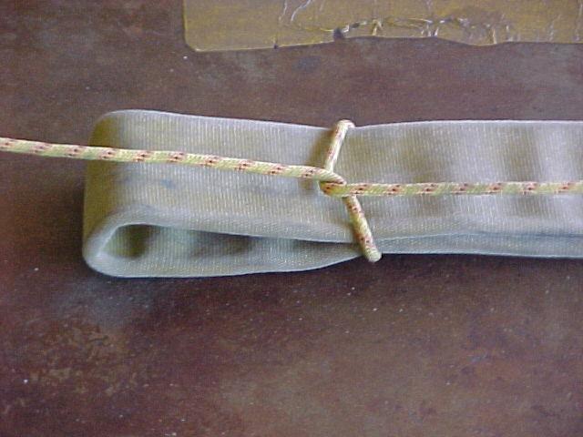
181 TYING OFF EQUIPMENT B2.4 B BB Fig. 1 Fig.2 182

182 AIR CHISEL B4.1 B BB 1. Attach regulator to compressed air supply (not oxygen). 2. Attach one end of air hose to regulation and other end to air chisel gun. 3. Select proper cutting chisel and install on gun using safety spring. 4. Use safety equipment while cutting. 183
183 SHORING BLOCKS / WEDGES & CRIBBING B7.1 B BB Blocks are of wood of various sizes 1. 4 x 4 Cribbing 2. 2 x 4 Cribbing 3. 4 x 4 Wedges 4. 2 x 4 Wedges MS 211 carries 2 boxes of: 12-4 x 4 Cribbing each box (yellow) 4-2 x 4 Cribbing each box (red) 4-4 x 4 Wedges each box (orange) 4-2 x 4 Wedges each box (orange) 184

184 SHORING BLOCKS / WEDGES & CRIBBING B7.1 B BB 185

185 VETTER SYSTEM B7.1 B BB 1. Attach regulator to a 2200 P.S.I. air bottle only. 2. Connect the green hose from the regulator to the control box. 3. Connect the yellow and red hoses to the appropriate air bags. 4. Position the bag in a manner to prevent sharp objects from puncturing the bag once inflated. 5. Inflate to achieve the desired effect. (may stack maximum of two bags) 186
186 TECHNIQUES AND EVOLUTIONS FOR GROUND LADDERS - 2 C1 C CC LADDER COMMANDS The majority of ladder work is performed by two or more personnel and requires teamwork. One key item in teamwork is the use of proper nomenclature and commands. Commands must be clear and concise and issued in tow parts; a preparatory command and an action command. In the preparatory phase, personnel place themselves in the proper position to start an evolution. On the action part of the command the evolution is begun. An example would be the command pick up (pause) ladder. On the words pick up personnel would prepare to pick-up ladder on the command ladder, the ladder would be picked up. The man who normally gives the commands is the one facing the rest of the personnel involved in the evolution. The only exception to this rule is when the order for the type of raise to be used is given. The man at the base of the ladder shall issue this command. The command must be given in a clear, sharp manner as the baseman has his back to the rest of the personnel, making voice contact more difficult. GENERAL LADDER TECHNIQUES 1. When the spurs can be placed in a crevice or crack by moving the ladder a few inches it should be done to provide additional stability. 2. The top of the ladder should not be scraped along a window or ledge when being shifted to a new position. The correct technique is to bring the ladder to the upright position and then reposition. On long ladders it may be necessary to lower the fly(s). 3. When extending or retracting the fly(s) the personnel securing the ladder are to support it by placing their hands on the beams, never reaching through the rungs for any reason. Care should be taken to be sure the hands are not exposed to guides or stops, which could cause injury. Feet should never be placed between the beams because of the danger of a halyard breaking, allowing the fly section to fall. 187
187 TECHNIQUES AND EVOLUTIONS FOR GROUND LADDERS - 2 C1 C CC 4. When lowering a ladder into a window, avoid knocking the glass from the frame, which might fall on the personnel below. 5. Ladders should not be placed in areas where ingress and egress to a structure might be obstructed. 6. When removing ladders from apparatus they shall be carried around the front of the apparatus to avoid interference with the unloading of hose. 7. When performing rescue operations involving a timid person, personnel are to take a position on the ladder with their feet one rung below the feet of the person being rescued; with the victim between rescuer and ladder, the rescuer s arm should go under the armpits of the victim and grasp the rungs. Descent is made one rung at a time. A ladder belt should be placed on a victim to assure the victim can be locked to the ladder in case of panic. 8. Should you lose control of the ladder when performing evolutions with the ladder in the vertical position, the ladder is to be pushed toward the buildings to limit the fall, thus, minimizing ladder damage and injuries to personnel. 188
188 LADDER PLACEMENT C2.2 C CC A good practice in determining the proper angle and distance to place butt of a ladder from the objective is 1/5 of the desired height plus 2. (Fig. 1) When working into an opening, from alongside of the opening, the ladder will be placed to the left of the opening. (Fig. 2) When going into an opening, the ladder will also be placed to the left with at least two rungs above windowsill. (Fig. 3) Ladders placed to the roof should extend a minimum of three rungs above the parapet or roof edge. (Fig. 4) 189


189 LADDER PLACEMENT C2.2 C CC Fig. 1 1/5 th of height + 2 Fig. 2 Fig. 3 Fig


190 PLACING ROOF LADDERS C2.2 C CC LADDERS ABOVE GROUND PLACING ROOF LADDER IN OPERATION ON PITCHED ROOF 1. Lock in on ground ladder. Remove roof ladder from shoulder, extend ladder toward ridge of roof by sliding ladder up roof on its beam, alternating your hands on the rungs. 2. Extend roof ladder until hooks drop over the roof ridge, turn the ladder on to its bed & pull ladder back toward ground, thereby setting points of hooks into roofing material. Revised 8/08/08 191
191 PLACING ROOF LADDERS C2.2 C CC 192
192 PROPER CLIMBING TECHNIQUE C2.4 C CC When climbing fire department ladders the body should be in an upright position. The arms should be out stretched with the elbows remaining straight to aid in keeping the body away from the ladder. This method is necessary to provide sufficient room for the knees to properly bend without striking the rungs when climbing. The hands are placed on every other rung, palms down, working through an arc between shoulder and waist level. The balls of the feet should be placed as near the center of the rungs as possible to minimize ladder sway. Feet are placed on every rung and the leg muscles are used to propel the body. The arms are used to steady or guide the climber. The eyes should be directed ahead or slightly higher than the climber never at the feet. A visual inspection of ladder condition should be made as the climber progresses up the ladder to insure that the climb can be made safely. 193

193 PROPER CLIMBING TECHNIQUE C2.4 C CC 194

194 BRACING LADDERS C2.4 C CC BRACING LADDERS FOR CLIMBING LADDERS UP TO AND INCLUDING 35 FOOT Until ladders are secured to the structure by ladder straps, they shall be braced when climbing. Baseman bracing: Baseman braces ladder by grasping the outside of both beams, palms toward rungs, arms extended slightly above shoulder level, feet spread, one leg extended back toward structure. Inward tension is maintained on beams to hold ladder tip firmly against building. 195
195 LOCKING IN C2.4 C CC 1. Climb ladder to desired location. Place one leg through ladder and over a rung. 2. Return foot back through the ladder, under the rung, in a manner so as to place the rung in the curve of the knee joint. Hook foot over beam; step down one or two rungs with the other leg to a comfortable position for the individual. 196


196 LOCKING IN C2.4 C CC 197

197 CLIMBING A LADDER CARRYING FIRE SERVICE TOOLS C2.4 C CC Many times during firefighting, a firefighter is required to carry equipment up and down a ladder. This procedure interrupts the natural climb either by the added weight on the shoulder or the use of one hand to hold the item. If the item is to be carried in one hand, it is desirable to slide the free hand under the beam while making the climb. This method permits constant contact with the ladder. Whenever possible, a rope should be used to hoist tools and equipment. 198
198 ASSISTING A VICTIM DOWN A LADDER C2.4 C CC When it is known in advance the ladder will be used for a window rescue, the ladder tip is raised only to the sill. This gives the victim easier access to the ladder. All other loads and activity should be removed from the ladder, which should be securely anchored at both the top and bottom if possible. Use three or four firefighters on a ladder rescue. For ground ladder rescues, at least two firefighters should be in the building and one on the ladder. If the victim is conscious, the firefighters in the building should lower the victim feet first from the building to the ladder. The rescuer on the ladder supports the victim and descends ladder. The rescuer on the ladder supports the victim and descends the ladder. The rescuer descends first, keeping both arms around the victim under the armpits, with hands on the rungs in front of the victim for support in case the victim slips or passes out. When descending aerial ladders, it may not be possible to place the arms around the victim as the side rails may be in the way. An unconscious victim is held on the ladder in the same way as a conscious victim except that the body rests on the rescuers supporting knee. Place the victim s feet outside the rails to prevent entanglement. Another way to lower an unconscious victim involves the same hold by the rescuer, except that the victim is turned around to face the rescuer. The position lessens the chance the victim s limbs will catch between the rungs. Smaller sized adults and children can be brought down a ladder by cradling them across the arms. 199


199 ASSISTING A VICTIM DOWN A LADDER C2.4 C CC 200

200 SECURING A LADDER TO A BUILDING C1.2 C CC Whenever possible, a ladder should be tied securely to a fixed object. A rope tool or safety strap can be used. Tying a ladder in is simple, can be done quickly and is strongly recommended to prevent the ladder from slipping or pulling away from the building. Tying in also frees personnel who would otherwise be holding the ladder in place. 201
201 COLLAPSIBLE LADDERS (ATTIC LADDERS) C2.2 C CC COLLAPSIBLE LADDERS Collapsible or attic ladders are generally constructed in 10 lengths. They are designed to be used in confined spaces or for attic access. The method of carrying the collapsible ladder is to position the ladder horizontally, waist high, with the tip forward. 1. Place the tip of the ladder against the edge of the cover board. Push the tip of the ladder into the attic between the board and the access frame. (Figure 1) 2. Open the ladder (Figure 2); position the adjustable feet for stability. 3. Climb ladder; remove cover. 202


202 COLLAPSIBLE LADDERS (ATTIC LADDERS) C2.2 C CC Fig. 1 Fig
203 RAISING 14' - 16' ROOF LADDER C3 C CC 1. Remove from apparatus. a. Place ladder onto the right shoulder supporting lower beam with the right hand and upper beam with left hand at the mid-point of ladder. 2. Butt the ladder. a. Dipping down and pitching the ladder. 3. Lower into the building. a. Place one foot on lower rung and grasp shoulder-high rung. 4. Remove from building. a. Place one foot on lower rung and grasp shoulder-high rung. 5. Shoulder Ladder. a. Pivot ladder so that beam faces the right shoulder. b. Place beam against the shoulder, supporting upper beam with left hand and lower beam with right hand. Walk backwards to the mid-point of the ladder, and then lift off of the ground. 6. Ground ladder. a. Butt ladder and walk backwards until you are at the top of the ladder. b. Grasp upper beam with left hand and pivot body facing top of ladder. c. Bend at knees and place ladder on the ground. 204


204 RAISING 14' - 16' ROOF LADDER C3 C CC d. 205
205 RAISING 24' & 28' EXTENSION LADDERS (ONE MAN) C3 C CC 1. Remove ladder from apparatus. a. Take a position at mid-point of ladder. b. Carry ladder on right shoulder; fly out. (or) 2. Shoulder ladder from the ground. a. Take a position at the tip of the ladder, your left side towards the ladder. b. Grasp beam with left hand. c. Lift upward and pivot towards butt of ladder. d. Place beam on right shoulder, and walk towards mid-point of ladder. e. When at the mid-point, lift butt off of the ground using leverage to assist. 3. Butt ladder. a. Pivot ladder so that fly is towards the building. 4. Extend fly. a. Support the ladder with your foot alongside the beam and knee against the same beam. 5. Lower Ladder into building. a. Place one foot on lower rung and grasp shoulder-high rungs and lower ladder into building. 6. Remove ladder from building. 7. Lower the fly. 8. Shoulder ladder. a. Pivot ladder so that beam faces shoulder and fly is out. b. Walk backward to mid-point of ladder and lift ladder off the ground. 9. Ground ladder. a. Butt ladder and walk backwards until you are at the top of the ladder. b. Grasp upper beam with left hand and pivot body facing tip of ladder. c. Bend at knees and place ladder on the ground, fly up. 206


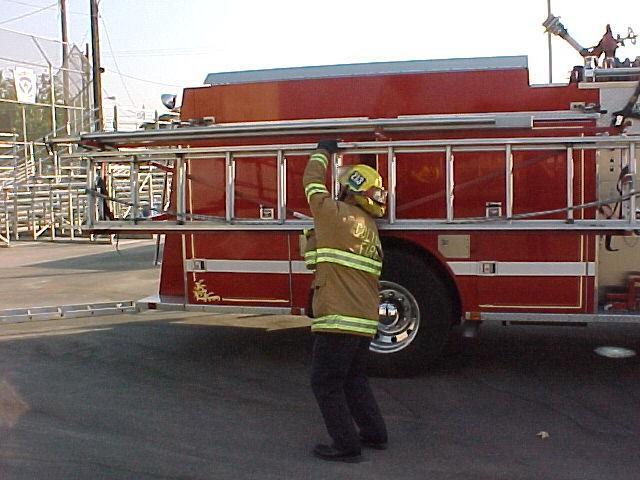
206 RAISING 24' & 28' EXTENSION LADDERS (ONE MAN) C3 C CC d. 207
207 RAISING 28' EXTENSION LADDER ( 2 MAN ) C3 C CC 1. Remove ladder from apparatus. (T211) a. Butt man grasps second rung with right hand and proceeds to pull ladder out of bed. b. Halyard man positions himself at ladder compartment and grabs 3 rd. rung from tip as the ladder is being removed. c. Immediately following removal of ladder, butt man gives command to rotate ladder, so fly section is out. At this time, arms should be placed through the 2 nd. & 3 rd. rung at each end grasping the bottom beam in right hand. d. Hip carry ladder to desired location. OR 2. Pick-up ladder from the ground. a. Butt man and halyard man position themselves at the side of the ladder facing the tip. b. Bending at the knee, grasp the beam with the left hand and lift upwards and pivot towards the butt of the ladder. c. Place arms through 2 nd. & 3 rd. rung at each end holding on to bottom beam. 3. Hip carry the ladder to the desired location. a. Fly out. 4. Butt ladder. a. But man places bottom beam on the ground and pivots ladder to a flat-raise position, fly towards building. 5. Raise ladder. a. Halyard man assists butt man in pivoting ladder to flat-raise position. Butt man places both feet on bottom rung, both hands on upper rungs and leans back. b. Halyard man walks ladder up using hand over hand method. 6. Extend fly. a. Both men place right foot next to beam. b. Butt man grasps beams about shoulder height and controls the ladder s forward and backward movement. c. Halyard man extends fly and assists butt man in stabilizing ladder. Revised 09/18/08 208
208 RAISING 28' EXTENSION LADDER ( 2 MAN ) C3 C CC 7. Lower ladder into the building. a. Halyard man assures dogs are locked. b. Halyard man places one foot on the bottom rung and grasps should height rung, butt man continues to support beams. Together they lower the ladder into the building. c. Butt man ties Bangor knot. 8. Remove ladder from building 9. Halyard man raises fly to unlock dogs then lowers fly section in a controlled manner. 10. Shoulder ladder. a. Halyard man walks back to the tip of the ladder. b. Butt man places both feet on the bottom rung, grasps upper rung and leans back. c. Both men pivot the ladder to hip-carry position. 11. Ground ladder. a. Butt man gives command ground ladder. In unison both men grasp beam with left hand, pivoting their body to face the tip of the ladder and lower ladder to ground bending at the knees. Revised 09/18/08 209


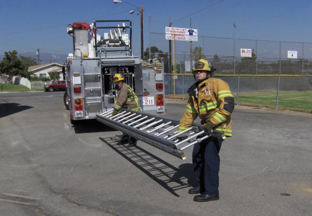
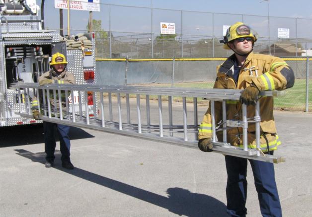
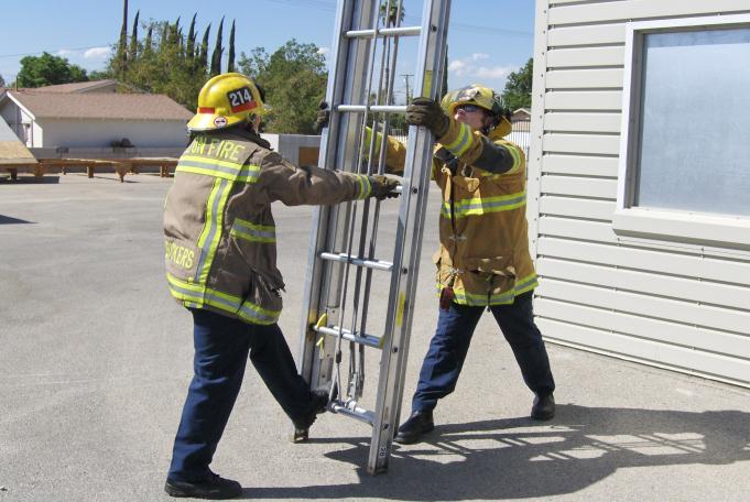
209 RAISING 28' EXTENSION LADDER ( 2 MAN ) C3 C CC 210
210 RAISING 35' EXTENSION LADDER C2.1 C CC 1. Removing ladder from truck. a. Firefighter #1 and firefighter #3 position themselves on one side of the ladder, while firefighter #2 positions himself on the opposite side. b. Firefighter #1 starts to remove ladder from truck by grabbing it between the 2 nd & 3 rd rung. Firefighter #2 assist at the 2/3 point and firefighter #3 positions himself at the tip, grabbing the ladder between the 2 nd. & 3 rd. rung. c. Firefighter #1 and #3 place ladder on their right shoulder so that ladder is in a flat carry position. d. Firefighter #2 positions the ladder on his left shoulder. Firefighter #3 moves up to a position directly across from firefighter #2. (or) 2. Picking up ladder from the ground. a. Two firefighters position themselves on one side of the ladder. i. Firefighter #1 at butt end. ii. Firefighter #2 2/3 from tip. b. Firefighter #3 positions himself across from #2. c. All three firefighter shall face the tip of the ladder. d. Firefighters bend at knees and grasp a rung, lift ladder and pivot towards butt and placing ladder on appropriate shoulder. 3. Flat carry ladder to the desired location. Revised 01/03/05 211
211 RAISING 35' EXTENSION LADDER C2.1 C CC 4. Butting the ladder. a. Firefighter #1 lowers butt plates so that the ladder is in a flat raise position with the fly towards the building. b. Firefighter #2 and #3 walk ladder to an upright position. 5. Extend fly. a. Firefighter #1 calls change positions. b. Firefighter #2 moves to his right. c. Firefighter #1 stabilizes the ladders forward and backward movement. d. Firefighter #2 grasps the right beam with both hands and stabilizes side-to-side movement. e. Firefighter #3 extends the fly and at the same time, assists Firefighter #1 in stabilizing the ladder. 6. Lower the ladder into the building. a. Firefighter #3 ensures the dogs are locked. b. Firefighter #1 calls change positions. Firefighter #2 moves to the left. c. Firefighters #2 and #3 place one foot on the bottom rung and grasp rungs about shoulder height then lower ladder into the building. d. Firefighter #1 ties halyard. e. Firefighter #1 then steps off the distance for the proper climbing angle. 7. Lower fly. a. Firefighter #1 unties Bangor knot. b. Firefighter #1 calls remove ladder from the building. c. Change positions and stabilize the ladder. d. Firefighter #3 lowers fly. e. Firefighter #1 calls change positions. 8. Shoulder ladder. a. Firefighters #2 and #3 walk back to their carrying positions, lowering the ladder as they go. b. Firefighter #1 places both feet on bottom rung, grasps shoulder high rung and leans back. c. After firefighters #2 and #3 reach their positions, firefighter #1 steps off ladder, pivots toward the butt end and places the ladder on right shoulder. 212
212 RAISING 35' EXTENSION LADDER C2.1 C CC 9. Grounding ladder. a. Firefighter #1 gives command to ground ladder. b. In unison, all three men grasp a rung and remove the ladder from their shoulder as they pivot to face the tip of ladder. c. Place ladder on ground, bending at the knees. 213


213 RAISING 35' EXTENSION LADDER C2.1 C CC Out of truck Pick up off ground 214


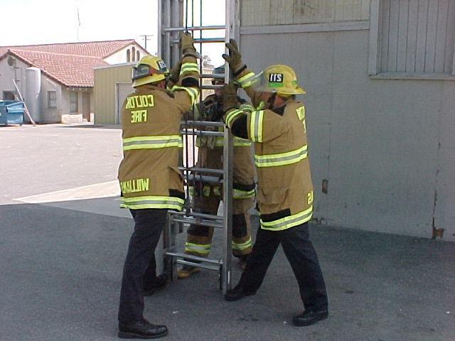
214 RAISING 35' EXTENSION LADDER C2.1 C CC 215


215 BANGOR KNOT C1.2 C CC The Bangor knot is used to lock the dogs on ladders not equipped with self-locking dogs. On other ladders, it is a convenient method to tie off excess rope. 216
216 PLACING LADDERS BELOW GROUND LEVEL C2.2 C CC 1. Remove ladder from apparatus. 2. Place ladder on the ground, resting on one beam. 3. Extend ladder-using halyard. When using a 35 ladder position one man at the middle and one man at the top to help guide 2 nd and 3 rd sections. 4. Ensure that the top section dogs are locked before the middle section. 5. Secure each section in place using ladder straps. 6. Tie off the halyard. 7. Place ladder flat on the ground. 8. Secure a rope to the 3 rd rung from the top. 9. Position one man on each side of the ladder, at the top of the bed section and one man at the top of the ladder. 10. Carry the ladder to the desired location and place over the edge. 11. Slowly push the ladder out until the pivot point is reached, then lower to the bottom. Top man controls the pivot with the rope. 12. To remove ladder reverse procedure. 217


217 PLACING LADDERS BELOW GROUND LEVEL C2.2 C CC

218 DONNING SELF-CONTAINED BREATHING APPARATUS/ E1.3 E EE 219

219 DONNING SELF-CONTAINED BREATHING APPARATUS/ E1.3 E EE 220

220 DONNING SELF-CONTAINED BREATHING APPARATUS/ E1.3 E EE 221

221 DONNING SELF-CONTAINED BREATHING APPARATUS/ E1.3 E EE 222

222 DONNING SELF-CONTAINED BREATHING APPARATUS/ E1.3 E EE 223

223 DOFFING SELF-CONTAINED BREATHING APPARATUS/ E1.3 E EE 224

224 DOFFING SELF-CONTAINED BREATHING APPARATUS/ E1.3 E EE 225

225 DOFFING SELF-CONTAINED BREATHING APPARATUS/ E1.3 E EE 226
226 DOFFING SELF-CONTAINED BREATHING APPARATUS/ E1.3 E EE 227

227 SELF-CONTAINED BREATHING APPARATUS/ COLD WEATHER OPERATION E1.3 E EE 228

228 QUICK FILL SELF-CONTAINED BREATHING APPARATUS/ E1.3 E EE 229

229 QUICK FILL SELF-CONTAINED BREATHING APPARATUS/ E1.3 E EE 230
230 QUICK FILL SELF-CONTAINED BREATHING APPARATUS/ E1.3 E EE 231

231 SELF-CONTAINED BREATHING APPARATUS/ CLEANING & DISINFCTING E1.3 E EE 232

232 INSPECTION SELF-CONTAINED BREATHING APPARATUS/ E1.3 E EE 233
233 SELF-CONTAINED BREATHING APPARATUS INSPECTION, CARE AND TESTING E2 E EE Firefighters should consider self-contained breathing apparatus to be an important part of their protective equipment. Like any other equipment, it has its limitations, which should be explored and understood in training sessions. Self-contained breathing apparatus requires proper inspection and care before each use, and testing and maintenance is necessary after each use. The maintenance and care program should revolve around four services: 1. Inspecting for defects. 2. Cleaning and disinfecting. 3. Repairing. 4. Storing. After Each Use 1. Replace cylinder with one fully charged. 2. Inspect O-rings and gaskets and screens at pressure connections. 3. Examine the face piece and hose. 4. Clean the face piece. 5. Rinse assembly under hose or faucet. 6. Wipe off unit with cleaner disinfectant. Inspect entire unit and test before placing back in service. 234
234 SELF-CONTAINED BREATHING APPARATUS INSPECTION, CARE & TESTING E2 E EE Daily or Weekly Check 1. Check face piece, cylinder and valve. Harness assembly, regulator and hose. 2. Check cylinder pressure. Check hydrostat-test date. 3. Check exhalation valve. 4. Check by-pass valves for proper position. 5. Check parts for defects. 6. Check gauges and low-pressure alarm. 7. Check to see if they are stored properly. 235
235 SELF-CONTAINED BREATHING APPARATUS INSPECTION, CARE & TESTING E2 E EE INSPECTION & MAINTENANCE CHECK LIST FOR SELF-CONTAINED BREATHING APPARATUS SERIAL NO. LOCATION IDENTIFICATION WEEKLY INSPECTION DATE INSPECTE D CYLINDER PRESSUR E CYLINDER DATE CHANGED INSPECTE D CYLINDER PRESSUR E CYLINDER DATE CHANGED INSPECTE D CYLINDER PRESSUR E CYLINDER DATE CHANGED INSPECTE D CYLINDER PRESSUR E CYLINDER CHANGED MONTHLY INSPECTION DATE CYLINDER INSPECTED PRESSURE CYLINDER CHANGED REGULATOR OK FACEPIECE OK CLEANED AND SANITIZED ENTIRE APPARATUS OK REMARKS INSPECTE D B Y Y Y 236
236 FILLING SELF-CONTAINED BREATHING APPARATUS E2 E EE 1. Check hydrostatic-test date and cylinder for damage. 2. Secure cylinder to breathing support trailer. 3. Open cylinder valve. Rotate door and push the door lock lever to the downward position. 4. Open fill valve. Fill slowly. 5. When SCBA is filled to 4500 PSI close the fill valve. 6. Move door lock lever to the up position, rotate door, close the cylinder valve and open the bleeder valve to release excess pressure. Remove bottle form breathing support trailer. 237
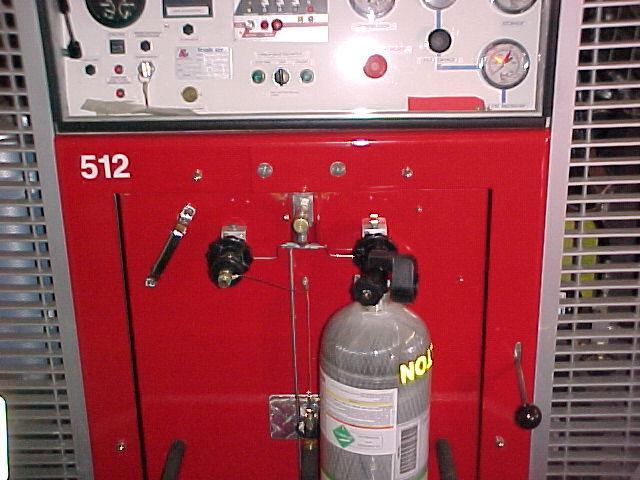
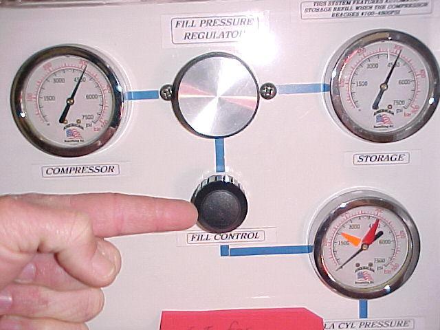
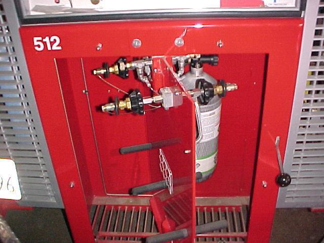
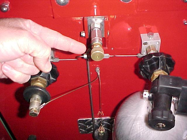
237 FILLING SELF-CONTAINED BREATHING APPARATUS E2 E EE 238
238 DONNING SCBA SELF-CONTAINED BREATHING APPARATUS E3 E EE Jump Seat Method Step 1: Step 2: Step 3: Step 4: Remove the face piece from the bag and place it nearby. Open the cylinder valve fully and check the air supply at the cylinder gauge and the regulator gauge. Back up against the cylinder back plate and place the arms through the harness straps. Secure the harness to the body. Fasten and adjust the waist straps. Remove helmet. Don the face piece and hood. Put helmet on. Connect regulator to mask when needed. 239

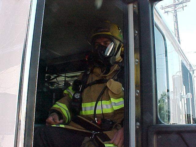
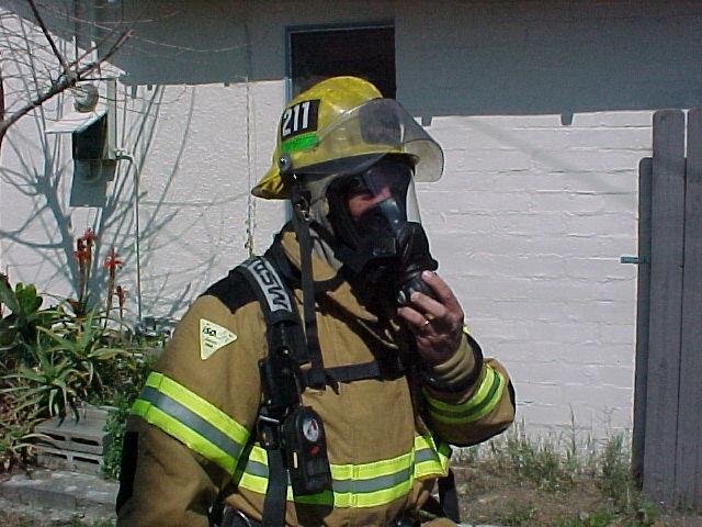
239 DONNING SCBA SELF-CONTAINED BREATHING APPARATUS E3 E EE 240
240 DONNING SCBA SELF-CONTAINED BREATHING APPARATUS E3 E EE COMPARTMENT MOUNT Step 1: Step 2: Step 3: Step 4: Step 5: Step 6: Open compartment door. Open the cylinder valve fully and check the cylinder gauge and regulator gauge. Grasp the back plate of cylinder with both hands, one at each side. There should be no straps between the hands. Lift the MSA from its mount and let harness clear compartment as you raise cylinder overhead. Keep elbows close to the body and let straps fall easily into place. Lean slightly forward to balance the cylinder on the back, and then fasten the waist strap. Next, fasten the chest strap. Pull down on the two shoulder straps. Shoulder straps should fit loosely so the weight of the SCBA is carried on your waist. Don the face piece and tighten. Don hood. Attach the mask-mounted regulator when needed. 241

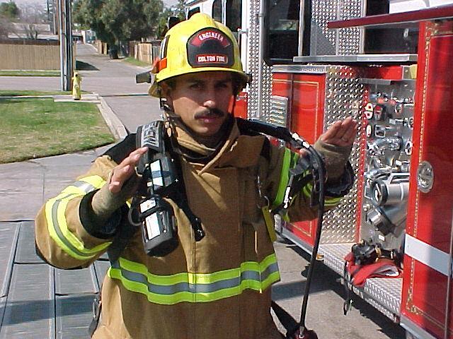
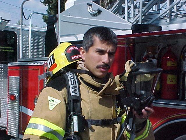
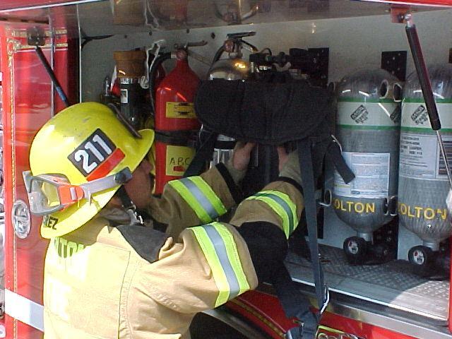
241 DONNING SCBA SELF-CONTAINED BREATHING APPARATUS E3 E EE 242
242 FOLDING SALVAGE COVERS SPLIT FOLD/PALO ALTO F1.2 F FF 1. Spread cover (finished side up) on a clean, dry surface. 2. Two men move to opposite ends of cover, turn all corners inwards about Place outside hands, palms down on end of cover, three feet in; grasp corners, fold in. 4. Repeat on opposite side of cover. 5. Place outside hands, palms down, along center line of first fold, reach over with inside hands, grasp corners, fold cover. 6. Brush air out of cover with broom. Remove wrinkles in cover before folding. 7. Two men take position at same end, one at each side, place outside hands, palm down, and nine to ten inches in. 8. Men place inside hands, palms up, under edge of cover, 8 to 10 inches from outside hands. 9. Cross inside hands over outside hands, making fold. Keep additional folds even. 10. Third man places hands in center of cover to avoid cover from wrinkling in fold. 11. Repeat operations until cover is folded. 12. A rubber band may be placed over each end to keep folds in place while transporting. 243
243 FOLDING SALVAGE COVERS SPLIT FOLD/PALO ALTO F1.2 F FF 244
244 FOLDING SALVAGE COVERS/STANDARD F1.2 F FF 1. Spread cover (finished side up) on a clean, dry surface. 2. Two men move to opposite ends of cover, turn all corners inward about Place outside hands, palms down, on end of cover, three feet in; with inside hand reach over and grasp the corner of cover and lap over. 4. Go to opposite side of cover and repeat same operation. This will bring the cover with both sides folded to the center. 5. Turn in corner of last double fold about Place the cut side hand flat on the border of the two folds, in center of cover, reach over with inside hand and fold cover. 7. Brush air out of cover with broom. (Remove wrinkles in cover before folding). 8. Both men place inside hands opposite each other, palms up under edge of cover, 8 to Bring inside hand up and over first hand, making fold. The folds may be kept even by keeping the thumb under the cover in making the pleat. 10. Repeat this operation until cover is fold. 245
245 FOLDING SALVAGE COVERS/STANDARD F1.2 F FF 246
246 SALVAGE COVERS / ONE MAN THROW F1.2 F FF 1. Place center of folded cover over either forearm; grasp bottom fold with fingers of that hand. 2. Reach in next to body with other hand and grasp the three top folds between thumb and fingers, thumb down. 3. Swing the arm back up and over shoulder, with the free folds falling over back of hand. 4. Throw the cover over the material to be covered, by bringing the hand forward and keeping the arm still while throwing. 5. Unfold and drape cover, tuck in at the bottom and sides. Note: On the standard fold the closed side is the center of cover. On Palo Alto fold, center of cover is on forearm for throwing. Line up center of cover with center of counter or merchandise before throwing. 247
247 SALVAGE COVERS / ONE MAN THROW F1.2 F FF 248
248 SALVAGE COVERS / COUNTER PAY OFF F1.2 F FF 1. Holder stands with folded cover on both forearms, (split toward holder), grasps bottom fold with both hands, center of cover next to objective. 2. Payer grabs top fold with both hands, walks backward, and stretches cover taut. Holder elevates forearms, applies tension, and keeps cover off floor. 3. Both men hover cover above objective, carefully lower centerfold of cover to center of object. 4. Unfold and drape cover. Tuck in at bottom. 249
249 SALVAGE COVERS / COUNTER PAY OFF F1.2 F FF 250
250 TWO MAN BALOON THROW F1.2 F FF 1. Counter pay off cover along one side of object to be covered, tension will keep cover off the floor. 2. Both men hold cover vertically, grasp the open edge and prepare to open the cover. 3. Each man reaches in, grasps a corner in each hand, palms down, elbows high. 4. Both men quickly snap center of cover up, form an air pocket under cover, lift cover up and over, let it float over object. Keep outside hand on cover and bring end of cover down. 5. If object is too tall you may let go with outside hand. 6. Straighten cover and tuck in at bottom. 251
251 TWO MAN BALOON THROW F1.2 F FF 252
252 SALVAGE COVERS JOINING / LEAKPROOF FOLDS F1.2 F FF 1. Spread covers over objective. Turn back about one foot of the cover. 2. Pull adjoining cover over the one-foot turn back, until edges are even. 3. All men grasp both edges and roll up the one-foot lap. 4. Repeat for all adjoining covers. 253
253 SALVAGE COVERS JOINING / LEAKPROOF FOLDS F1.2 F FF 254
254 SALVAGE COVERS - JOINING / HANGIN COVERS F1.2 F FF 1. Hang covers at point higher than shelves or racks. Use suitable ladder, cord, S hooks, or nails through grommets. 2. Overlap covers one foot at joints. 3. Overlap covers two feet where water is coming through. 4. Tuck covers in at bottom. 255
255 SALVAGE COVERS - JOINING / HANGIN COVERS F1.2 F FF 256
256 SALVAGE COVERS - STAIRWAY CHUTE F1.2 F FF 1. One-man throw cover down stairway. 2. Open up cover. Roll edges underneath. 3. Both sides form dike. 4. Stair banister and wall support chutes. 5. Use leak proof fold to place two covers together for longer chute. 257

257 SALVAGE COVERS - STAIRWAY CHUTE F1.2 F FF 258
258 SALVAGE COVERS - REMOVING COVERS FROM COUNTER F1.2 F FF 1. Two men take positions opposite each other at one end of counter. 2. Each man grasps edge of cover and raises clear of counter. 3. Both men walk to other end carrying cover until edges meet. 4. Grasp edges and raise clear of counter, walk back and place edges even with centerfold. 5. Grasp edges and center fold and lap cover over again. 6. Grasp ends and fold to center and continue fold for shoulder carry. 7. One-man places shoulder on cover, second man places folds on first man s shoulder. 259
259 SALVAGE COVERS - REMOVING COVERS FROM COUNTER F1.2 F FF 260
260 SALVAGE COVERS - BACK TO QUARTERS FOLD F1.2 F FF 1. Grasp center of cover at end. (one man at each end). 2. Raise cover so that edges are clear of ground or floor and shake back and forth to remove debris. Note: Cover is half folded during this operation. 3. After flipping cover several times, lay on ground or floor, fold from closed edge to open edge. (Fig. 1) Repeat (Fig. 2) 4. Bring one end to within about two feet from opposite end. (Fig. 3) 5. Roll cover loosely from closed end to open end. (Fig. 4) 6. Place rolled cover on apparatus. 261
261 SALVAGE COVERS - BACK TO QUARTERS FOLD F1.2 F FF Constructing Fig. 1 a Catchall Fig With cover spread upon the floor, roll the sides inward about three feet. 2. Lay the ends of the side rolls over at a 90-degree angle to form corners. (Fig. 1) 3. Roll one end into a tight roll on top of the side roll forming an ear. (Fig. 2) 4. Using outside hand to lift edge roll, tuck end roll to lock corners. (Fig. 3) Constructing a Catchall Alternative An alternative to Steps 2 and 3 is to merely bend the end of the first rolled edge outward, and then roll the side up to it and tuck the ear under the side to complete the corner. (Fig. 1, 2 & 3) Fig. 3 Fig
262 SALVAGE COVERS - CONSTRUCTING A CATCHALL F1.2 F FF CONSTRUCTING A CATCHALL 1. With cover spread upon the floor, roll the sides inwards about three feet. 2. Lay the ends of the side rolls over at a 45-degree angle to form corners. 3. Roll one end into a tight roll on top of the side roll forming an ear. 4. Using outside hand to lift edge roll, tuck end roll to lock corners. 5. Roll other end in a like manner. CONSTRUCTING A CATCHALL ALTERNATIVE An alternative to steps 2 and 3 is to merely bend the end of the first rolled edge outward, and then roll the side up to it and tuck the ear under the side to complete the corner. 263


263 : SALVAGE COVERS - CONSTRUCTING A CATCHALL / CONSTRUCTING A CATCHALL ALTERNATIVE F1.2 F FF 264
264 : SALVAGE COVERS - CATCH BASIN OR SUMP F1.4 F FF 1. Form a square triangle or circle with objects at hand. Note: Extension and roof ladder, kitchen table and chairs furniture may be used. 2. Place salvage cover over objects, forming a basin in center. Pay off cover over objects. 3. Tuck in at bottom; use rope if necessary to hold side. 265
265 : SALVAGE COVERS - CATCH BASIN OR SUMP F1.4 F FF 266
266 : SALVAGE COVERS - WINDOW DRAIN F1.4 F FF 1. Fasten center grommet of cover to windowsill; fasten remaining grommets to window frame. 2. Draw cover taut, secure sides and ends by means of nails S hooks or cord. Form a chute by allowing cover to sag. 267
267 : SALVAGE COVERS - WINDOW DRAIN F1.4 F FF 268
268 : SALVAGE COVERS - WINDOW DRAIN USING PIKE POLES F1.4 F FF 1. Spread cover flat. 2. Lay two poles along opposite ends or sides at desired angle handles extended past cover. 3. Place hook points through grommets, fold down edge of cover to clear hooks. 4. Lap and roll poles and cover toward middle of cover to form desired width. 5. Place handles out of window. Secure or prop upper end of drain. 269
269 : SALVAGE COVERS - WINDOW DRAIN USING PIKE POLES F1.4 F FF 270
270 : SALVAGE COVERS / WINDOW DRAIN USING LADDERS F1.4 F FF 1. Secure end of ladder over windowsill, rungs down. 2. Place opposite end of ladder under ceiling hole. Secure or prop end of ladder to desired height. 3. Place salvage cover at end of ladder extending over windowsill. Pay off cover toward ceiling hole. 4. Secure cover to ladder with cord. 5. Hang another cover by means of nails, S hooks, or cord to form a guide chute under ceiling hole. 271
271 : SALVAGE COVERS / WINDOW DRAIN USING LADDERS F1.4 F FF 272
272 : SALVAGE COVERS / CARE OF SALVAGE COVERS F1.2 F FF 1. Salvage covers need care in order to last. 2. They must be thoroughly washed and dried before placing in service. a. Use a mild soap and water and scrub brush. b. Rinse thoroughly and hang to dry. 3. Inspect covers for holes and tears. a. Two men place cover over their heads and work to each end of cover, marking existing holes. 4. Repair all holes, cut and tears in following manner: a. Use large enough patch of good quality canvas. (Round corners of patch) b. Apply contact cement to damaged area and patch. Wait required time for glue to become tacky. c. Place patch on cover, press firmly, allow to dry. 5. Covers shall not be thrown down elevator shafts or windows when removing from building. 6. Covers should be removed from floors and stairways, as soon as possible, and walking over covers unnecessarily is strictly forbidden. 7. Covers should never be spread on floors, or sidewalks over broken glass or other sharp pieces of debris. 8. Use the grommets only for hanging and securing salvage cover. Do not drive nails through canvas. 9. When covering roof openings remove nails, tin and other sharp objects so as to protect cover. Use wood lath to secure cover, make sure nails are in grommet hole. Keep edges secured to keep cover from flapping. Plastic covers should be used whenever possible. 10. All salvage covers shall be refolded monthly. 273


273 : SALVAGE COVERS / CARE OF SALVAGE COVERS F1.2 F FF 274
 Water Vacuum (Industrial) Small quantities of water can be removed from floors in any area by using a portable water vacuum.")
274 : SALVAGE COVERS / REMOVING WATER F1.4 F FF REMOVING WATER (MECHANICAL) Water Vacuum (Industrial) Small quantities of water can be removed from floors in any area by using a portable water vacuum. This operates similar to an ordinary cleaner except that the electric motor is arranged to enable the water collected to be stored in a metal or plastic container. 275

275 : SALVAGE / REMOVING WATER (OTHER DEVICES) F1.4 F FF When water collects on the floor this indicates a need for its removal. Floors react to prolonged dampness by warping, swelling and buckling. Additional tools and equipment used to remove excess water from buildings include brooms, squeegee, buckets, mops, shovels and sawdust. 276


276 : SALVAGE / REMOVING WATER (PUMPS) F1.4 F FF Colton Fire Department is prepared to remove large amounts of water from properties when storms or floods cause excessive damage. Portable water pumps with large capacities, which are powered by small internal combustion engines, are ideal for this purpose. Two examples of portable pumps are shown in Figures 1 and 2. The processors electric submersible pump is lightweight and easy to use. The trailer mounted portable pump is for heavy-duty operations. Fig. 1 Fig. 1 Fig. 2 Fig
277 : SALVAGE SALVAGE COVERS OVER FIREPLACE OPENINGS F1.2 F FF Salvage covers are placed over fireplace openings to protect the rooms, fixtures and contents from soot, ashes, etc., when extinguishing a chimney fire. 1. Open up end portion of cover. 2. Place edge of cover over mantel. Note: Covers should not be placed where likely to be damaged by fire. 3. Secure cover by means of weights, S hooks, or nails. Note: Where fireplaces have no mantel, short pike pole with points placed through grommets and braced will hold cover in place. 4. Tuck cover in at bottom and place weights on it. CAUTION: Covers placed over fireplace require constant attention to prevent damage from sparks. 278


278 : SALVAGE SALVAGE COVERS OVER FIREPLACE OPENINGS F1.2 F FF 279
279 : SALVAGE TESTING SALVAGE COVERS F1.2 F FF New covers or covers which have been in service and about which there is doubt concerning their protective qualities may be tested by the lake test. The lake test procedure is as follows: 1. Spread cover on flat smooth surface (floor or driveway). 2. Make a catchall. 3. Fill basin with water to a depth of approximately five inches. 4. Let stand for at least 12 hours. After water is removed there should be no signs of excess leakage on the underside. Leakage should not be confused with normal bleeding or sweating. 280


280 : SALVAGE USING SPRINKLER SHUT OFF TOOLS F1.4 F FF Considerable time may elapse from the moment of activation of a sprinkler head until authorization to close the main sprinkler valve is received. Plugging the individual heads, which are no longer needed for fire extinguishments, can prevent excessive water damage. Located in the salvage box on the engines are redwood wedges and sprinkler. If properly applied, the stops will permit no dripping from a plugged sprinkler head. 281

281 : SALVAGE OVERHAUL F1.3 F FF Overhaul is the practice of searching a fire scene to detect hidden fires or sparks, which may rekindle, and to detect and safeguard signs of arson. The building is to be left in as safe and habitable condition as possible. Many of the tools and equipment used for overhaul are the same as those used for other firefighter operations. Some tools and equipment used for overhaul, along with the uses, may include: 1. Pike poles, plaster hooks opening ceilings to check on fire extension. 2. Axes Opening walls and floors. 3. Carryalls and buckets to carry debris or immersing smoldering material. 4. Shovels, hooks and forks to move loose material. 282
282 : SALVAGE VALUE OF PROPER OVERHAUL F Helps locate hidden fires. 2. Helps prevent rekindle. 3. Helps determine cause of fire. 4. Aids recognizing and preserving evidence of arson. 5. Helps prevent unnecessary damage. 6. Permits removal of original fire cause. 7. Aids in placing building in safe condition. 8. Helps improve public relations. 283

283 : SALVAGE OVERHAUL SAFETY F4 F FF For the safety of firefighters during overhaul full protective clothing should be worn including positivepressure S.C.B.A. When opening a ceiling with a pike pole, wear full protective clothing. 284
284 : SALVAGE COVERING ROOFS AND WINDOWS F1.2 F FF Salvage and overhaul operations should continue even after the fire is completely extinguished, other wise merchandise or furnishings previously protected could become damaged by the weather. Coverings should be provided for broken windows, doors or open roofs. 285
285 : HYDRAULICS BASIC FORMULAS l. Introduction A. Purpose: To provide Department personnel with a simple and accurate method for determining fireground hydraulics. B. Scope: Department members when determining fireground hydraulics will use these calculations as guidelines. II. Policy A. Apparatus operators shall be responsible for hydraulic calculations within (+) or (-) five pounds for any given hose evolution. Fireground Hydraulics Basic formulas An increasing need for a method to simplify hydraulic calculations has existed since the development of organized fire departments. The County of Los Angeles Fire Department has developed a workable method for fireground operations. Equipment operators must be able to compute required engine pressures within (+) or (-) five p.s.i for any given hose lay (s). The method of determining calculations contained in this text is based on time-tested, nationally recognized formulas. However, some formulas have been simplified and quantities rounded off for easy use. It shall be incumbent upon all members to study and review publications such as Water Supplies for Fire Protection, Aerial Apparatus and Pumping Apparatus by the International Fire Service Training Association, in order to understand hydraulics as used in the Fire Service. 286
286 : STANDARD HANDLINE - NOZZLE PRESSURE G2 G GG The concept of fire ground hydraulics has two fundamentally established formulas. Two facts must be obtained to initiate the use of this practice in fire ground hydraulics: 1. Gallons of water per minute (GPM), to be used at the fire scene. a. The formula developed to ascertain the gallons per minute flow through a smooth orifice is 29.7 D² /NP = GPM, which is the formula used in fire ground hydraulics. 2. Friction loss (FL) involved in carrying the water to the desired location through the hose must be established. a. The formula used to determine friction loss in pounds per hundred feet of 2-1/2 inch hose is: FL = 2Q² + Q (Q = gallons in hundreds) Example: 300 GPM = (3) This formula is used only when gallonage is over 100 GPM. Fifty pounds has been established as the desired nozzle pressure (NP) for handline operations with smooth bore nozzles on 2-12 inch hose. There is no logical reason to use any other nozzle pressure on these to project a fire stream a greater or lesser distance. Accepting this fact, the following smooth bore tips and nozzle pressures have been established as the standard for handlines (Table I) TABLE I STANDARD HANDLINES NOZZLES PRESSURE Size Tip Nozzle Pressure / /4 50 By using this accepted and established formula for finding gallons per minute flowing through a smooth bore nozzle, take the 1-inch nozzle at 50 pounds nozzle pressure and establish gallons per minute. 287
287 : STANDARD HANDLINE - NOZZLE PRESSURE G2 G GG Example: 29.7 D² /NP = GPM 29.7 x 1 x 1 /50 = 209 This answer of 209 gallons is exact when checking the discharge tables in Fire Service Hydraulics, but this is where the simplified method of fire ground hydraulics is established. It has been established that 200 gallons per minute is the gallonage for a 1-inch smooth bore tip at 50 pounds nozzle pressure. In continuing to find the friction loss for 200 gallons per minute, use the 2Q² + Q = FL formula: 2 x 2² + 2 = 10, or 10 pounds loss per 100 feet of 2-1/2 inch hose for 200 gallons per minute. By using the same pressure, calculate the gallonage and friction loss for 1-1/8 inch and 1-1/4 inch smooth bore nozzles. Using the gallons per minute formula it is determined that the 1-1/8 inch and 1-1/4 inch smooth bore nozzles. Using the gallons per minute formula it is determined that the 1-1/8 inch nozzle delivers 265 gallons per minute at 50 pounds nozzle pressure. The hydraulics is simplified by rounding off this figure to 250 gallons per minute. Using the friction loss formula, the friction loss per hundred feet of 2-1/2 inch hose is calculated at 15 psi. The 1-1/4 inch smooth bore nozzle, by calculation, delivers 326 gallons per minute at 50 pounds nozzle pressure. Rounding this figure off to 325 gallons, the friction loss of 25 pounds per 100 feet of 2-1/2 inch hose is calculated. By making additional calculations, 300 gallons per minute equals 21 pounds friction loss and 400 gallons per minute equals 36 pounds friction loss. Placing these figures on a scale, various gallonages and friction losses can be interpolated. TABLE II FL GPM The gallons per minute flowing through the four standard nozzles at a standardized nozzle pressure and the friction loss per 100 feet of 2-1/2 inch hose have been established. (See Table III) 288
288 : MULTIPLE LINES G GG Engine Pressure When the nozzle pressure and the friction loss are known, the engine pressure (EP) may be determined with the formula: EP = NP + FL. Four standard nozzles have been adopted for use on 2-1/2 inch handlines, as shown in the following table. TABLE III Nozzle Size GPM NP FL / / *Fog (constant flow) As long as the gallons per minute remain the same, a fog nozzle, which delivers 250 gallons per minute at 100 pounds of nozzle pressure, would have a related 15 pounds friction loss per 100 feet of 2-1/2 inch hose. Example: Answer: Using the standard nozzle pressure (Table III), calculate the engine pressure for an engine company pumping through 500 feet of single 2-1/2 inch hose with a 1-1/8 inch nozzle tip at 50 pounds nozzle pressure. EP = NP + FL NP = 50 pounds FL = 75 (15 x 5) EP = = 125 pounds Engine Pressure Engine 2 1/2" 1-1/8 tip 289
289 : MULTIPLE LINES G GG Fog Nozzle 100 Pounds psi For any fog nozzle on ¾, 1, 1-1/2, 1-3/4 or 2-1/2 inch hose lines, use 100 pounds nozzle pressure. New type combination fog and straight stream nozzles have a constant flow in gallons per minute in either straight stream or fog pattern. No mention is made of size other than size of hose on which the nozzle is used. All specifications are in gallons per minute at 100 pounds nozzle pressure. Heavy Streams Smooth Bore Nozzles 80 psi To be effective, heavy stream appliances require pressure above those for handlines. Smooth bore nozzles for heavy stream appliances range from 1-1/4 to 2 inches. Eighty pounds nozzle pressure has been established as the standard pressure. The discharge of these tips will be from 400 to 1000 gallons per minute. (See Table IV) Table IV Nozzle Size GPM NP 1-1/ / / / / Note: The above chart indicates that, at 80 pounds nozzle pressure, each increase of 1/8-inch nozzle size increases the gallons per minute by 100 gallons. Heavy Stream Appliances Through practical test, 15 psi has been established as being the average loss by friction of water pressure entering a heavy stream appliance, i.e., monitor, deluge set, cellar pipes, and ladder pipes. 290
290 : MULTIPLE LINES G GG Basic Formula For Multiple Lines When two or more lines are used to supply water to a desired point or appliance, calculations are simplified by considering only the friction loss per 100 feet of one line. Each hose line will deliver its equal amount of water to the desired point because the pressure applied by the pump will equalize itself in each line. When multiple lines are used to supply large volumes of water to heavy stream appliances, the engineer must know the total number of lines supplying the appliance, the length of the lines he is pumping into, and the size and/or type of tip being used. By knowing these factors, the engineer is able to determine gallons per minute on the fire ground. (See Table IV) Example: Determine the engine pressure for an engine pumping through 300 feet of dual 2-1/2 inch hose into a monitor using a 1-3/4 inch nozzle. 1-3/4 tip 2 1/2" Engine 2 1/2" Solution: Table IV initiates that the 1-3/4 inch nozzle discharges 800 gallons per minute at 80 pounds nozzle pressure. Divide the two lines into 800 gallons per minute. Each line will supply 400 gallons per minute. Friction loss for 400 gallons per minute is 36 pounds per 100 feet of 2-1/2 inch hose. To determine engine pressure for the problem, add the friction loss in the hose to the desired nozzle pressure (in this instance, 80 pounds) and 15 pounds for friction loss in the appliance. Answer: EP = NP + FL (Hose) + FL (Appliance) NP = 80 pounds FL = 108 (36 x 3) (Hose) FL = 15 pounds (Appliance) EP = = 203 pounds Engine Pressure 291
291 : MULTIPLE LINES, SIAMESE OR WYE G GG Note: Minimum pump capacity for this example is 1250 gallons per minute. A 1000-gallon per minute pumper can supply only 700 gallons per minute at 200 pounds engine pressure. If a third line is added, the friction loss would be reduced to 17 pounds per 100 feet of hose, as each line would then supply approximately 266 gallons per minute, instead of 400 gallons per minute. It would now be possible to supply the problem using a 1000-gallon per minute pumper. For fast mental calculations in planning hose lays, the addition of a third line will cut the friction loss in half, thus allowing the pumper to supply the problem from twice the distance. Siamese or Wye As previously mentioned, greater volumes of water will cause more friction loss. This has been found true in water flowing through a Siamese or wye. A standard of 10 pounds friction loss in a Siamese and wye has been established. This loss must be included in the solution for engine pressure. To solve for engine pressure where Siamese lines are used, the same principle used in heavy streams is applied with one addition; the total gallonage is returned to one line and friction loss is calculated on this basis. Example: Determine the engine pressure for an engine pumping through two lines of 2-1/2 inch hose, 400 feet in length, connected by a Siamese and continued 100 feet to a 1-1/4 inch tip. 2 1/2" ME /2" 2 1/2" Answer: EP = NP + FL (Dual) + FL (Single) + FL (Siamese) NP = 50 pounds FL = 28 (7 x 4) (Dual) FL = 25 (Single) FL = 10 (Siamese) EP = = 113 pounds Engine Pressure 1-1/4 tip 292
292 : HEAD PRESSURE & STANDPIPES G GG Head Pressure When vertical distance, either above or below pumping equipment is involved, add or subtract ½ psi per foot for head pressure (H). When water is pumped above or below grade in structures, add or subtract 5 psi for each story above or below the first floor. Standpipes 25 psi While the actual friction loss under ordinary conditions for a standpipe riser is almost negligible, there is a loss at the Siamese connection and at the outlet valve flowing to the fittings and reduction in flow area. For calculation purposes, an allowance of 25 pounds for friction loss in the standpipe is required. Example: Determine the engine pressure for an engine pumping through a single 2-1/2 inch line, 300 feet in length, into a standpipe; 100 feet of 2-1/2 inch line has been connected to the standpipe outlet on the fifth floor and advanced up the stairway to the sixth floor. A 1-1/8 inch nozzle is being used. ME /2" Combining the 300 feet of hose going into the standpipe with 100 feet attached to the standpipe outlet, there is a total of 400 feet of 2-1/2 inch hose, using a 1-1/8 inch nozzle. 293
293 : HOSE CONVERSION - LARGE LINES G GG Referring to Table II, a 1-1/8 inch nozzle requires 50 pounds nozzle pressure and delivers 250 gallons per minute, and the friction loss is 15 pounds per 100 feet of hose. Next, find the engine pressure necessary to overcome the friction loss in the hose and provide 50 pounds nozzle pressure. To these figures, add the Head Pressure (H) (five pounds per floor above the first floor) and friction loss allowed for standpipe connection (25 pounds), which gives the engine pressure necessary to complete the problem. Answer: EP = NP + FL + H + FL in standpipe NP = 50 FL = 60 (4 x 15) (Hose) H = 25 (5 x 5) (Head) FL = 25 (Standpipe) EP = = 160 pounds Engine Pressure Note: When two or more lines are connected to the standpipe outlet above ground, determine which line requires the highest pressure and pump to that line. Hose Conversion Large Lines In the previous pages, the simplified method of determining friction loss in 2-1/2 inch hose, using the basic 2Q* + Q formula, has been described. To calculate friction loss in various sizes of hose other than 2-1/2 inch, factors have been established to convert the larger and smaller hose into 2-1/2 inch hose. This method converts the gallons per minute delivered through the various sizes of hose into equivalent gallons per minute through 2-1/2 inch hose. Before explaining the procedure for solving the following problems, it must be remembered that these factors are correct to within less than five percent of published friction loss tables, provided that the problems are within reasonable limits, e.g., limits for 3-1/2 inch hose, 1000 gallons; for 3-inch hose, 700 gallons; for 1-1/2 inch hose, 150 gallons; for 1-inch hose, 50 gallons; and for 3/4 inch hose, 30 gallons. 294
294 : HOSE CONVERSION - LARGE LINES G GG 4 Inch to 2-1/2 Inch Hose Factor 0.2 The conversion of gallons per minute flow in four inch hose to the equivalent gallons per minute flow in 2-1/2 hose is calculated by multiplying the gallons per minute delivered through 4 hose by the factor of /2 Inch Hose to 2-1/2 Inch Hose Factor 0.4 The conversion of gallons per minute flow in 3-1/2 inch hose to the equivalent gallons per minute flow in 2-1/2 hose is calculated by multiplying the gallons per minute delivered through 4 hose by the factor of 0.4. Example: 800 gallons per minute are being delivered through 3-1/2 hose. The equivalent gallons per minute in a 2-1/2 inch hose will then be 800 x 0.4 = 320 GPM. Referring to table II, the friction loss for 320 gallons per minute is 24 pounds per 100 feet of hose. At this point, the problem reverts to a standard 2-1/2 inch hose problem, all other variables, i.e., length of hose, appliances, siamese, head pressure, nozzle pressure, etc., are totaled to obtain the engine pressure. Example: Determine the engine pressure for an engine pumping through 400 feet of 3-1/2 inch hose wyed into two 2-1/2 inch hose lines of 300 feet each with 1-1/8 inch nozzles. 1-1/8 tip ME /2" 2-1/2" 2-1/2" 1-1/8 tip 295
295 : HOSE CONVERSION - LARGE LINES G GG Solution: To solve this problem, first determine the gallons per minute being delivered, 500 gallons per minute (1-1/8 inch tip = 250 GPM); multiply the factor 0.4 by 500 gallons per minute, which is the gallons per minute equivalent in 2-1/2 inch hose, or 200 gallons per minute. Using the basic friction loss formula, the friction loss is 10 pounds per 100 feet of 2-1/2 inch hose, or a loss of 40 pounds in the 400 feet of 3-1/2 inch hose. The balance of the problem is the same as previous solutions, i.e., 300 feet of 2-1/2 inch hose with 1-1/8 inch tip = 45 pounds loss. The wye causes a 10-pound loss and the nozzle pressure is 50 pounds, for a total of 105 pounds loss in the wyed lines. Adding the 40 pounds loss in the 3-1/2 inch hose gives us a total of 145 pounds. Answer: EP = FL (3 ½ ) + FL (2 ½ ) + FL (Wye) + NP FL = (10 x 4) 3 1/2 hose FL = 45 (3 x 15) 2 ½ hose FL = 10 Wye NP = 50 EP = = 145 pounds Engine Pressure By knowing the factor for 3-1/2 inch hose and how to apply it, these complex hose lays become nothing more than a 2-1/2 inch hose lay problem. Keep in mind that gallons per minute of various sizes of hose are being converted into equivalent gallons per minute in 2-1/2 inch hose. The first step in solving any problem is to determine the gallons per minute for any given nozzle or nozzles. 3 Inch Hose to 2-1/2 Inch Hose Factor 0.6 The factor of 0.6 will be used when converting gallons per minute flow in 3-inch with 2-1/2 inch couplings to the equivalent gallons per minute flow in 2-1/2 inch hose. Some fire departments use this size hose for supplying multiple lines, heavy stream appliances, and ladder pipe operations. Therefore, it is suggested that the factor 0.6 be remembered. The same procedure is used to find the equivalent flow for 3-inch hose as for 3-1/2 inch hose. 296
296 : HOSE CONVERSION - DUAL LINES & SMALL LINES G GG Dual Lines Single 2-1/2 inch and Single 3-1/2 inch Factor 0.3 The conversion of gallons per minute flow of water in dual lines of single 2-1/2 inch and 3-1/2 inch hose to the equivalent gallons per minute flow in single 2-1/2 inch hose is calculated by multiplying total gallons per minute by the factor 0.3. Hose Conversion Small Lines 1-3/4 inch to 2-1/2 inch Hose Factor 2.0 The conversion of gallons per minute flow in 1-3/4 inch hose to the equivalent gallons per minute flow in 2-1/2 inch hose is calculated by multiplying the gallons per minute delivered through 1-3/4 inch hose by the factor 2.0. The same procedure is used to find the equivalent flow for 1-3/4 inch hose as for 3-1/2 inch hose. 1-1/2 inch to 2-1/2 inch Hose Factor 4.0 The conversion of gallons per minute flow of water in 1-1/2 inch hose to the equivalent gallons per minute flow in 2-1/2 inch hose is calculated by the same method which was used for the 3-1/2 inch and 3-inch hose by substituting the factor 4.0 in place of the other factors. Standard nozzle pressure for handlines has been established previously in this Manual for the majority of fire conditions. In rural or forest firefighting, there may be the exception to the rule as to nozzle pressure because of water availability or extreme length of hose lays. In these instances, the officer may ask for a minimum of nozzle pressure, such as 25 pounds; there for, the engineer must know the gallons per minute flow of various tip sizes from 1/4-inch to 7/8-inch and constant flow nozzles. The following table lists the gallons per minute at various nozzle pressures. 297
297 : DISCHARGE OF SMOOTH NOZZLES & HOSE CONVERSIONS G GG Step II With the friction loss known, the problem is nothing more than multiplying the friction loss by the length of hose (4 x 12 = 48) and add the nozzle pressure of 50 pounds, for a total of 98 pounds for engine pressure. Solution: GPM 2-1/2 inch hose = 1-1/2 inch hose GPM x 4.0 GPM 2-1/2 inch hose = 120 (30 x 4.0) Answer: 120 GPM (equivalent for 2-1/2 inch hose) Answer: EP = FL + NP FL = 48 (4 x 12) (120 GPM) NP = 50 EP = = 98 pounds Engine Pressure 1 - inch to 2-1/2 inch Hose Factor 11 The Factor II will be used when converting gallons per minute in 1-inch hose to the equivalent gallons per minute flow in 2-1/2 inch hose. To convert 1-inch hose, the same procedure is followed which was used to convert the previous hose sizes (3-inch, 3-1/2 and 1-1/2 inch). Example: Step I Step II Determine the engine pressure of an engine pumping through 1000 feet of 1-inch hose with a 1/4-inch tip at 50 pounds nozzle pressure. Solve for equivalent flow in 2-1/2 inch hose. The discharge tables show that a ¼ - inch tip a 50 pounds nozzle pressure delivers 13 gallons per minute; therefore, factor 11, multiplied by 13 gallons, equals 143 gallons, equivalent flow for 2-1/2 inch hose. Using the friction loss formula 2Q² + Q = FL, a friction loss of approximately 5-1/2 pounds per 100 feet is calculated. This is the basic formula: Answer: EP = NP + FL NP = 50 FL = 55 EP = = 105 pounds Engine Pressure 298
298 : PUMP CAPACITIES & HOSE LAYS G GG ¾ inch to 2-½ inch Hose Factor 24 The factor 24 will be used when converting gallons per minute flow in ¾ inch hose to equivalent gallons per minute flow in 2 ½ inch hose. The same procedure is used as in the previous conversion problems. Example: Determine the engine pressure for an engine pumping through 500 feet of ¾ inch hose, with a ¼ inch tip, at 50 pounds nozzle pressure. Step I GPM 2 ½ inch hose = GPM ¾ inch hose x 24 GPM 2 ½ inch hose = 312 (13 x 24) Friction Loss = 23 pounds per 100 feet Step II EP = NP + FL NP = 50 FL = 115 (23 x 5) EP = = 165 pounds Engine Pressure Pump Capabilities A pump is rated on its ability to discharge its raged capacity, operating at draft with a vertical lift of not over ten feet, at a net discharge pressure of 150 psi. Also, the pump must discharge 70 percent of the rated capacity at 200 psi, and 50 percent if the rated capacity of 250 psi. In efficient pumper utilization, pump capacities at various pressures is the first factor that a pump operator must understand. A maximum of 250 pounds working pump pressure should not be exceeded when pumping through single or double jacket hose. Hose Lays Short, Medium and Long To determine the maximum length of a hose lay that can be used with any of the three basic smoothbore nozzles for handlines, i.e., 1 inch, 1 1/8 inch, 1 ¼ inch, start with a net working pressure of 200 pounds. Allowing the standard 50 pounds for nozzle pressure on handlines, this leaves an available working pressure of 150 pounds to overcome friction loss. (See Table VII) 299
299 : PUMP CAPACITIES & HOSE LAYS G GG Nozzle pressure on handlines, this leaves an available working pressure of 150 pounds to overcome friction loss. (See Table VII) Short Lay A short lay would be the maximum length of hose that would supply a 1-1/4 inch nozzle delivering 325 gallons per minute at 50 pounds nozzle pressure. Table III indicates a friction loss of 25 pounds per 100 feet of 2-1/2 inch hose. Deducting 50 pounds nozzle pressure from the net working pressure of 200 pounds leaves an available 150 pounds which will be used to over come the friction loss in the hose lay. If the available working pressure of 150 pounds is divided by the friction loss (25 pounds) per 100 feet for the gallons per minute delivered, we have 150 divided by 25 = 6, or 600 feet. This is the maximum length of 2-1/2 inch hose for a 1-1/4 inch nozzle delivering 325 gallons per minute per minute at 50 pounds nozzle pressure. Medium Lay A medium lay is the maximum length of hose that will supply a 1-1/8 inch nozzle delivering 250 gallons per minute. The available working pressure of 150 pounds is divided by the friction loss (15 pounds) per 100 feet for the gallons per minute delivered or 150 divided by 15 = 10, or 1000 feet. Long Lay A long lay is the maximum length of hose that would supply a 1-inch nozzle delivering 200 gallons per minute. The available working pressure of 150 pounds is divided by the friction loss (10 pounds) per 100 feet for the gallons per minute delivered, or 150 divided by 10 = 15, or 1500 feet. TABLE VII Engine Hose Feet of Tip Pressure Layout 2 ½ Hose Size GPM FL NP 200 Short / Medium / Long
300 : RELAY PUMPING G3.3 G GG Relay Pumping When establishing relay operations, unlike maximum hose lays for single pumpers, the following items must be considered in making an efficient relay operation: (1) gallons per minute needed at the fire ground; (2) distance water must travel from the source; (3) size of the hose, (4) maximum distance one pumper can deliver the gallons per minute; (5) number of pumpers needed; and (6) topography. The following additional items must be considered: The largest capacity pumper should be placed at the source of supply and ensuing pumpers should be placed so that the smallest capacity pump will be at the fire. This arrangement enables you to have the maximum pumping capabilities with the equipment available for any condition that may arise. The maximum distance that water can be delivered is accomplished in three ways, by: (1) increasing the size of the hose (2) additional lines, and (3) using additional pumpers. The first two methods described should be utilized to full capacity of the pumper before considering using additional pumpers. If the required flow can be delivered at the proper pressured, there is no point in pumping with additional apparatus. Calculating engine pressure to be pumped to a relay pumper or supply reservoir, a pressure of 20 pounds allowed for intake pressure is subtracted from the net working pressure of 250 pounds, leaving 230 pounds available for friction loss. In relay operations, the total engine pressure required to deliver the water to the fire determines the number of pumpers needed. Example: 250 gallons per minute are needed to supply a 1-1/8 inch nozzle 4200 feet from the source of supply. Using a single 2-1/2 inch line for relaying, we have a friction loss of 15 pounds per 100 feet, or a total of 630 pounds (15 x 42). This, plus a nozzle pressure of 50 pounds, equals 680 pounds pressure. To determine the number of pumpers, divide 680 pounds by the available working pressure of 230 pounds (250 pounds net working pressure less 20 pounds IP), which equals 2.9, or a total of three pumpers needed to deliver the required gallons per minute. 301
301 : RELAY PUMPING G3.3 G GG Now, the distance between pumpers and the engine pressure required for each pumper must be determined: Solution: Step I The distance between pumpers is calculated by dividing the 230 pounds of available pressure by 15 pounds friction loss per 100 feet; = or 1500 feet between pumpers. The problem looks like this: A EP = 245 Engine B EP = Engine C EP = /8 S.B. 250 GPM Engine Step II Pumper A, B Pumper C EP = FL plus IP EP = NP plus FL FL = 225 (15x15) FL = 180 (15x12) IP = 20 NP = 50 EP = EP = = 245 = 230 If elevation had been involved in the above problem, either above or below the pumpers, head pressure would cause a need for an increase or decrease in the engine pressure. 302
302 : FRICTION LOSS - OTHER THAN STANDARD NOZZLE PRESSURE G GG Friction Loss Constants Smooth Bore Nozzles Using Other Than Standard Nozzle Pressure Handlines To determine engine pressure using other than the standard nozzle pressure, constants have been developed to be used with the various smooth bore nozzles based on the following conditions: (1) any increase or decrease will be in increments of 5 pounds nozzle pressure. (2) Any increase or decrease of nozzle pressure will be limited to 10 pounds above or below the standard nozzle pressure. The limitation of 10 pounds is to assure a reasonable nozzle pressure with gallons per minute flow from approximately 175 to 360 gallons per minute through single 2-1/2 inch hose. To calculate engine pressure for handlines, when an increase or decrease from the standard nozzle pressure is required, the following constants are used. For a 1-inch smooth bore nozzle, the constant is 1 for a 1-1/8 inch smooth bore nozzle, the constant is 1-1/2 for a 1-1/4 inch smooth bore nozzle, the constant is 2 These constants are to be considered as pounds. For each five-pound nozzle pressure above the standard nozzle pressure, add the constant to the friction loss per 100 feet of 2-1/2 inch hose. For each five-pound decrease in nozzle pressure, subtract the constant from the friction loss per 100 feet of 2-1/2 inch hose. Example: Solution: Answer: Note: The engine pressure for an engine pumping through 600 feet of 2-1/2 inch hose, using a 1-1/8 inch nozzle, is 140 pounds engine pressure. An increase of ten pounds nozzle pressure is desired; determine engine pressure. With an increase of ten pounds nozzle pressure, add 1-1/2 pounds for each five pounds nozzle pressure increase per 100 feet of hose being used. This totals three pounds per 100 feet, and for the 600 feet totals 18 pounds (3 x 6), plus the ten pounds nozzle pressure increase, equals , or 28 pounds to be added to the engine pressure = 168 pounds Engine Pressure. See Table VIII for discharge through smooth bore nozzles using other than standard nozzle pressure. 303
303 : FRICTION LOSS - OTHER THAN STANDARD NOZZLE PRESSURE G GG Friction Loss Constants Using Other Than Standard Nozzle Pressure Heavy Streams To determine engine pressure using other than the standard nozzle pressure, a constant was developed to be used with all heavy stream smooth bore nozzles based on the following: (1) Any increase or decrease will be in increments of five pounds nozzle pressure. (2) Any increase or decrease will be limited to 15 pounds is to assure a reasonable nozzle pressure with a gallons per minute flow from approximately 360 to 1100 gallons per minute. When exceeding these pressures, it is indicated that a change in tip size is required. To calculate engine pressure for all heavy stream smooth bore nozzles above or below the standard nozzle pressure, the constant ½ pound per 100 feet of 2-1/2 inch hose. Example: Supplying a 1-1/2 inch tip with a standard nozzle pressure through 300 feet of dual 2-1/2 inch hose to a monitor equals 158 pounds engine pressure. A decrease of ten pounds nozzle pressure is desired; determine engine pressure. Solution: With a decrease of ten pounds nozzle pressure desired, ½ pounds for each five pounds nozzle pressure decrease must be subtracted from the engine pressure. This totals one pound per 100 feet or three pounds for 300 feet, plus ten pounds nozzle pressure decrease equals or 13 pounds to be subtracted from the engine pressure. Answer: = 145 pounds engine pressure required. TABLE VIII DISCHARGE THROUGH SMOOTH BORE NOZZLES HANDLINES Nozzle Pressure 1 1-1/8 1-1/4-10# # Std. N.P # #
304 : HEAVY STREAMS & AERIAL LADDER STREAMS G GG Heavy Streams Nozzle Streams 1-1/4 1-3/8 1-1/2 1-5/8 1-3/4 2-15# # # Std. N.P # # # Constants for fog nozzles have not been considered; they are primarily designed to operate at a standard nozzle pressure of 100 pounds and it will not increase its effectiveness to vary the nozzle pressure. Aerial Ladder Streams Aerial ladder companies use 100 feet of 3-1/2 inch hose up the ladder to the appliance. When possible, connect the 3-1/2 inch hose directly to the pumper discharge gate at the base of the aerial. Quick calculations with the ladder at 60 feet elevation, using a Siamese, are shown in Table IX. Note: The Table below indicates that for each 100 gallons per minute increase the pressure required at the base of the ladder will increase five pounds. Table IX Nozzle Size GPM Pressure Required at Base of Base of Aerial Ladder 1-1/ / / / /
305 : HEAVY STREAMS & AERIAL LADDER STREAMS G GG Continued Nozzle Size GPM Pressure Required at Base of Base of Aerial Ladder Fog NP=100 psi appliance =15psi ladder pipe =30psi head 35 psi fully extended TOTAL = 180 PSI NOTE: T211 use flow meter. For engines pumping to T211, pump thru the inlet at 180 PSI, plus friction loss for hose on the ground. Revised 06/20/08 306
306 : HEAVY STREAMS & AERIAL LADDER STREAMS G GG 307
307 : ARIAL PLATFORM STREAMS & ESTIMATING AVAILABLE FLOW (HYDRANTS) G GG Aerial Platform Streams The apparatus supplying water to the base of the aerial platform should pump to the inlet on the rear of the aerial platform. The pressure gauge on the Siamese should indicate the pressure for the nozzle being used, as shown in Table X. TABLE X Pressure Required at Nozzle Size GPM Base of Aerial Ladder 1-1/ / Fog Estimating Available Flow From Hydrants This method of calculating the flow (gallons per minute) available from a fire hydrant is of value to both the pump operator and the commanding officer. Available flow is calculated on the fire ground by testing and noting the static pressure (water at rest) and the residual pressure (water in motion) of fire hydrants. To estimate the available flow from a hydrant, the rule is to determine the percentage drop in pressure from static to residual. This percentage drop indicates the additional flow available. A drop of ten percent or less indicates an availability of three more like volumes. An 11 to 15 percent drop indicates two more like volume are available. A 16 to 25 percent drop indicates that only one more like volume can be handled. Example: The pumper is connected to the hydrant and the suction is charged. Before opening the discharge gate, the operator notes the static pressure is 60psi. He then opens the discharge supplying a 250 the compound gauge is 51 psi, a drop of nine pounds. This is a 15 percent drop in pressure and means that the hydrant can supply an additional 500 gallons per minute. 308
308 : ESTIMATING HYDRANT FLOWS G3.4 G GG Solution: With a decrease from static to residual pressure of nine pounds (60 51) the percentage of drop is 9/60, or 15 percent; therefore, two more like volumes is the estimated available flow, or a total estimated flow of three like volumes. Estimated Available Flow From Hydrant With Line In Operation If the static pressure was not noted when the hydrant was opened, and it is required in order to estimate the available flow, this can be determined as follows: 1. Note the residual pressure on the compound gauge with the first line in operation. 2. Place a test nozzle delivering the same gallons per minute into operation and note the drop in residual pressure. 3. Divide the drop in pressure by two and add to the residual pressure which was noted when the first line was in operation. This will enable you to estimate the static pressure. Example: With the first line in operation, the residual pressure on the compound gauge is 68 pounds. A test nozzle delivering the same gallons per minute is placed into operation and the residual pressure on the compound gauge is now 44 pounds. Estimate the remaining available flow. Solution: To estimate the static pressure with a decrease in residual pressure of 24 pounds (68 44), divide 24 by two, which equals 12 pounds. This is to be added to the residual pressure which was noted when the first line was in operation. Combining equals an estimated static pressure of 80 pounds. Next to estimate the remaining available flow; with a decrease from static to residual pressure of 12 pounds (80 68), the percentage of drop is 12 /80 or 15 percent; therefore, two more like volumes is the estimated available flow, or a total estimated available flow of three like volumes. 309
309 : HELISPOT PUMPERS & SPRINKLER SYSTEMS G3.4 G GG Helispot Pumper Operation When a pumper is assigned to supply water to helicopters, a 2-1/2 inch hose line is layed to the helispot and capped with a 2-1/2 inch WYE. Pumping 36 PSI per 100 feet of hose line will provide 30 psi at the WYE and deliver 350 GPM through an additional 50 feet of 2-1/2 inch hose line to a D- handle shut-off, 15 feet of 2-1/2 inch hose and a kam-lok coupling which mates with a kam-lok fitting on the helicopter water tank. Example: 300 feet of 2-1/2 inch hose line from engine to WYE. E.P. = WYE Pressure divided by F.L. E.P. = 30 PSI divided by (36) x 3 E.P. = 30 divided by 108 (E.P. = 138 PSI) Automatic Sprinkler System When using an automatic sprinkler system, an engine company shall lay a minimum of two 2-1/2 inch hose lines to the sprinkler connection inlet and maintain an engine pressure of 150 pounds. If one line is not sufficient to obtain this engine pressure additional lines must be laid into the system until 150 pounds engine pressure can be maintained. The minimum gallonage for efficient coverage by a sprinkler head is 15 gallons per minute and most authorities agree that the minimum acceptable efficient range is 15 to 25 gallons per minute. A 750-gallons-per-minute pumper will need more than two lines if located more than 200 feet from the sprinkler connection, as it can supply approximately 35 heads. A 1000-gallons-per-minute pumper will need more than three lines if located more that 2000 feet away from the sprinkler connection since it can supply approximately 50 heads. Weight of Water Delivered It is necessary to know that a standard fire stream, 250 gallons per minute, represents approximately one ton of water per minute being delivered into a building. Consideration should be given to safety of personnel due to the possibilities of structural collapse, and provisions for the release of water from a building is imperative. 310
310 : WEIGHT OF WATER & TANK CAPACITIES Below is a table relating the size of nozzle to the approximate tons of water delivered per minute. Table XI WEIGHT OF WATER DELIVERED Nozzle Water per Minute 1-1/8 1 ton 1-3/8 2 tons 1-5/8 3 tons 2 4 tons Capacity of Cylindrical Tanks During fires or other emergencies, when rapid calculations must be made to find the capacity or amount of water in a cylindrical tank and the dimensions are in feet, the following formula may be used: Q = 6D² x H, where Q equals quantity in gallons; D equals diameter in feet; and H equals height of water in feet. Example: Solution: A tank 20 feet in diameter has five feet of water in the tank. Determine the gallons of water in the tank. Q = 6D² x H Q = 6 (20) x 5 Q = 6 (400) x 5 Q = 2400 x 5 Q = 12,000 gallons For greater accuracy, subtract two percent (.02) from the above answer (12,000 x.02 = 240), which equals gallons. This answer approximates the National Fire Protection Association s Gallonages Tables for cylindrical tanks, ( gallons). 311
311 : PUMP OPERATIONS FOG NOZZLE FLOW CHART A.3 A AA Fog Nozzle Flow Chart SIZE HOSE NOZZLE MAKE OR MODEL OF HEAD PRESSURE FOG 1 Akron Turbojet Adjustable /23/30 1-1/2 Elkharts SM/TSM-10F Constant SM/TSM-15F Constant SM/TSM-20F Constant KK Product FS2095BC Adjustable Task Force Tip Mid-Matic Constant Elkhart SM/TSM30F Constant /2 Akron Akromatic Constant * Considered as solid stream nozzle ** Gallonage varies from 300 GPM at straight stream to 500 GPM at 90-degree fog pattern 312
312 : PUMP OPERATIONS FOG NOZZLE FLOW CHART A.3 A AA 1. Make hydrant 2. Advance engine to fire 3. Set brake 4. Engage pump 5. Place transmission in proper gear 6. Switch radio to outside speaker 7. Clamp hose at least 51 feet from tailboard 8. Open tank to pump valve 9. Open appropriate discharge valve to appropriate line when nozzleman calls for water 10. Set proper engine pressure 11. Set relief valve 12. Pull adequate amount of hose and connect to auxiliary suction 13. Release hose clamp 14. Close bleeder valve 15. Open suction valve 16. Close tank to pump valve 17. Note residual pressure 18. Slowly fill tank GPM LENGTH ENGINE PRESSURE
313 : PUMP OPERATIONS 2-1/2" REVERSE LAY A 2.6 A AA 1. Stop Engine at fire 2. Firefighter pulls 2-1/2 working line as ordered 3. Firefighter remove 2-1/2 nozzle and 2-1/2 double male from engine 4. Firefighter holds hoses and releases engine 5. Engine advances to hydrant 6. Set brake 7. Engage pump 8. Place transmission in proper gear 9. Switch radio to outside speaker 10. Connect front suction to hydrant 11. Charge front suction 12. Open front suction valve 13. Note Static pressure 14. Pull adequate amount of the 2-1/2 working line and break 15. Place 2-1/2 double female on discharge port 16. Connect 2-1/2 working line male coupling to 2-1/2 double female 17. Charge working line when nozzleman calls for water 18. Set pressure 19. Set relief valve 20. Note residual pressure 314
314 : PUMP OPERATIONS 4" SUPPLY LINE WITH 1-3/4" PRECONNECT 1. Make hydrant 2. Advance engine to fire 3. Set brake 4. Engage Pump 5. Place transmission in proper gear 6. Switch radio to outside speaker 7. Open tank to pump valve 8. Charge preconnect (s) when nozzleman call for water 9. Set proper pressure 10. Set relief valve 11. Connect supply line to suction (front or side) 12. Honk air horn twice 13. Open suction valve (after suction line is charged) 14. Note residual pressure 15. Slowly fill tank 315
315 : PUMP OPERATIONS 4" SUPPLY WITH 2-1/2" WORKING LINE 1. Make hydrant 2. Advance engine to fire 3. Set brake 4. Engage pump 5. Place transmission in proper gear 6. Switch radio to outside speaker 7. Pull adequate amount of hose and break 8. Connect supply line to front or side suction 9. Honk horn twice 10. Open suction valve (after supply line is charged) 11. Note compound gauge for static pressure 12. Hook female end of 2-1/2 (pulled by firefighter) to discharge 13. Charge 2-1/2 when nozzleman calls for water 14. Set proper pressure 15. Set relief valve 16. Note residual pressure 316
316 : PUMP OPERATIONS KEY POINTS a. Check for valves and drains in the wrong position b. Check for loose or missing equipment c. Insure road transmission is in neutral before engaging pump d. Lock pump in position when applicable e. Lock road transmission in proper gear when applicable f. Take out kinks in suction line g. Open and close all valves slowly h. Maintain proper pressure of operating lines within 10 psi i. Insure nozzleman is ready before charging line j. Lock discharge valves when lines are in operation k. Set pressure regulating device after first line is in operation l. Note static pressure before flowing water (if applicable) m. Note residual pressure after lines are in operation n. Check water temperature and oil pressure periodically o. Use proper shut down procedures: a. Throttle down slowly b. Close discharge valves c. Close relief valve or shut off governor d. Open bleeder valves e. Reset transfer valve (if applicable) f. Take pump out of gear g. Close bleeder valves h. Replace all equipment i. Avoid any unnecessary pressure fluctuations when adjusting throttle or charging other lines 317
317 : PUMPING PROCEDURES OPERATING FROM TANK Operating From Tank This operation is the simplest and the most often used method of pump operation in the fire service. 1. The pump operator opens the tank suction valve. This opening allows water to flow from the water tank to the pump. 2. The pump operator starts or engages his pump. 3. The pump operator opens the desired discharge valve, in this case the hard line. The water after reaching the pump is placed under pressure and moved through the desired discharge by opening or closing specific valves. Atmospheric pressure applied to water tank forces water into pump. Engine 318
318 : PUMPING PROCEDURES PUMPING FROM HYDRANT 1. Supply line from hydrant is charged to pump. 2. Note static pressure. 3. If the operator has his pump engaged, using tank water and operating a discharge line he should decrease his engine pressure by throttle reduction and at the same time slowly open his 2-1/2 intake. This valve opening will compensate for the throttle reduction of pressure and keep a smooth and constant pressure at the nozzle. 4. After fully opening the 2-1/2 intake, the operator reads his compound gauge and makes a mental note of his residual pressure. (The pressure showing on the compound gauge after a discharge line has been opened and water is flowing). 5. If the operator is not operating from his water tank and the water that he plans to discharge is coming directly from the hydrant he should open his intake valve and obtain the static pressure from his compound gauge. Knowing this static pressure permits the operator to calculate the drop in percent in pressure when supplying one line. The operator can then determine if the hydrant supply is adequate for subsequent discharge lines. After one discharge line is charged and opened, the compound gauge will show the residual pressure. The following rule of thumb method can be used to determine the number of additional discharge lines that can be supplied at the same capacity. a. If the drop is not more than 10 per cent: three additional lines each equal to the original lines capacity may be added. b. If the drop is not more than 15 percent: two additional lines each equal to the original lines capacity may be added. c. If the drop is not more than 25 percent: one additional line equal to the original line equal to the original line may be added. 6. The residual pressure on the compound gauge should normally not be permitted to drop below 10 psi. If it does or the operator notices a sudden drop in his residual, he will be forced to reduce his discharge by closing down lines or reducing his tip sizes. Many things can cause a drop in residual pressure, such as a broken discharge line, falling water supply to the hydrant system, or a 319
319 : PUMPING PROCEDURES PUMPING FROM HYDRANT broken water main. However, most often it is due to additional engine(s) drawing water from the same water main system. 7. If the pump operator has used or drained his water tank before starting hydrant operations, he can easily fill his tank by partially opening his tank filler valve while conducting his pumping operations. 4" Engine 320
320 : PUMPING PROCEDURES PUMPING FROM DRAFT G1.3 G GG In rural areas where hydrants are either few or non-existent, drafting may be the only way to obtain water. Drafting can also be implemented to increase fire flow when hydrant systems are inadequate. The scientific and hydraulic basis for drafting is contained in the pump theory handbook. However, a pump in good condition will only lift water 15 to 20 feet. A. Close tank suction valve. B. Close all discharges. C. Connect hard suction (airtight) and strainer (hand tight). D. Connect hard suction-to-suction intake (airtight). E. Lower suction and strainer into water, tie off strainer to engine or other solid object. This tie off line will enable you to adjust strainer depth (must be at least inches under water) and assist in removing suction hose from the static water supply. In sandy creek bottoms or in silted water a shovel should be placed under the suction strainer to prevent pump damage and nozzle clogging. The suction strainer may also be placed in a canvas bag to accomplish the same purpose. F. Engage or start pump. Let engine idle. G. Engage primer system. (Some manufacturers require that the pump be primed and then engaged or started). When the air in the suction hose is being displaced by water you will notice the hose becoming heavier. The primer motor noise will change to a deeper sound when water enters the primer pump, also when water reaches the pump the primer overflow line will discharge water or a water and oil mix. H. Keep your eye on your pressure and compound gauges. As soon as you obtain your prime. The engine pressure gauge will show a positive PSI reading. The compound gauge will show a negative reading in inches of vacuum while priming. I. Slowly open the desired discharge valve(s). J. Slowly adjust your engine pressure to the required reading. 321
321 : PUMPING PROCEDURES PUMPING FROM DRAFT G1.3 G GG When your primer is out of service it is still possible to obtain a prime and draft. 1. You must still have from 30 to 50 gallons left in your water tank. 2. Connect your suction hose and strainer as outlined in the previous steps. 3. Open your tank suction valve, and if equipped, your suction intake valve. This will allow the tank water to fill the pump and suction hose. 4. Let the air bubbles rise from your strainer for a few seconds. 5. Quickly engage the pump and slowly increase engine RPM s. 322
322 : PUMPING PROCEDURES PUMPING INTO STANDPIPES G3.5 G GG Some buildings have standpipe systems, which serve fire hose outlets in various parts of the structure. These systems allow the fire service to quickly place streams into operation in areas, which may be difficult to reach. The biggest advantage of a standpipe system is that it allows firefighters to move water through a pre-plumbed system to great elevations which otherwise require the laying of hose up ladders, stairwells, fire escapes or the use of hose hoists. Calculating the engine pressure necessary to pump water through a standpipe system is no different than calculating engine pressure for any other type of above ground pumping. However, because you are using a plumbing system rather than your own hose to assist in reaching the fire, you should consider the following: A. Figure head based on elevation of nozzle above the pump. B. Add 25 psi for friction loss in the system. C. Check standpipe intake points for debris. D. Flush the standpipe discharge ports before connecting your attack lines. Standpipes often contain much foreign matter. E. Whenever possible use your own hose. Hose supplied in house protection boxes may not be serviceable. 323
323 : PUMPING PROCEDURES PUMPING INTO STANDPIPES G3.5 G GG Example: EP = NP + or H + (FL x LL) GPM PSI NP 15 PSI Head 25 PSI Standpipe System 5 PSI Parallel Lines (10x2) divide ¼ F.L. 10 PSI 100 ft. 2-1/2 F.L. Single Line EP = 105 PSI 2 1/2" 2 1/2" 324
324 : PUMPING PROCEDURES PUMPING INTO SPRINKLER SYSTEMS G3.5 G GG PUMPING INTO SPRINKLER SYSTEMS 1. Lay two 2-1/2 lines from the Fire Department connection to the water supply. 2. Connect supply hose to FDC and pumper. 3. Slowly set your engine pressure to 150 PSI. As additional sprinkler heads fuse and open, more water will be discharged. Thus to maintain adequate flow and pressure at the sprinkler heads, you must maintain your engine pressure at 150 PSI. 4. DO NOT increase your engine pressure above 150 PSI. Pressures above 150 PSI may cause severe damage to the sprinkler system plumbing. 5. DO NOT rob water that is feeding the sprinkler system. 5" 2 1/2" 2 1/2" 325
325 : HOW TO MEASURE FLOW FROM A HYDRANT H2.3 H HH 1. Attach (Static-Residual) gauge to 2-1/2 outlet. 2. Turn on hydrant and record Static Pressure on Summary Sheet. a. No water flowing. 3. Turn additional hydrant completely on. a. Record residual pressure on summary sheet. b. If pressure drops less than 10 psi open additional hydrants. 4. Take pitot pressures on flowing hydrants. 5. Record outlet diameter on summary sheet. 6. Figure total G.P.M. flowed. a x P b. 2-1/2 167 x P c..9 constant figured in calculations. 7. Complete flow chart. a. Determine proper scale. b. Locate total discharge during test on the horizontal scale. c. Locate the residual pressure on the vertical scale. d. Make a point where both lines intersect. e. Locate static pressure on vertical scale. f. Draw a straight line from the static pressure point through the residual pressure point to the G.P.M. water flow scale on bottom of chart. g. Read G.P.M. available at 0 psi and record on summary sheet. h. Read the G.P.M. available at psi and record on summary sheet. 326
326 : HOW TO MEASURE FLOW FROM A HYDRANT H2.3 H HH WATER FLOW TEST SUMMARY SHEET HYDRANTS NOS. OUTLET DIAMETER INCHES PITOT PRESSURES PSI DISCHARGE GPM 1 4" Location Date Static psi Residual psi TOTAL DISCHARGE DURING TEST G.P.M AVAILABLE G.P.M. AT 20 psi AT 0 psi WATER FLOW CHART 327
327 : HOW TO MEASURE FLOW FROM A HYDRANT H2.3 H HH 328

328 : PRYING TOOLS I1.2 I II Ram Bar Hux Bar Halligan Axe There are many different designs of prying tools used in the Fire Service. These tools are very effective in breaking locks, opening doors, forcing windows, and prying up objects. 329

329 : PULLING TOOLS I1.2 I II Pike Pole Rubbish Hook Pike poles are useful as striking and pulling tools. They can be used to open windows, ceilings, and partitions. The rubbish hook was originally designed to move debris during overhaul operations and stripping shingles from roofs. It can also be used as a sounding tool during roof ventilation operations, removing roof decking, and opening plaster or dry wall. 330

330 : CUTTING TOOLS I1.2 I II Pick-Head Axe The pick-head axe is generally considered a more versatile tool for firefighting than the flathead axe. The pick-end may be used for pulling lathe and plaster, removing sheathing, stripping shingles and shakes from roofs as well as cutting with the blade end. The pick-head axe can also be used for prying. Due to the grain of the wood in wooden handles, the strongest axis when using an axe to pry is in-line with the grain of the wood. Care must be used when prying against the direction of the grain of the handle. For the reason, the pick-head axe is not the tool of choice when forcing open doors and double hung windows. 331

331 : CHAIN SAW I1.2 I II The chain saw can significantly simplify numerous ventilation operations. It is effective on roofs with wood decking, cutting heavy layers of roof composition usually found on older homes. Unlike other power saws the chain saw can be used to feel or read the rafters or joists to determine their location and spacing. The chain saw exhibits significant hazards that must be considered when operating the saw. 1. Most of the chain and cutting teeth are exposed. This requires constant operational and safety considerations by the saw operator. 2. Although most chain saws are equipped with a centrifugal clutch, the chain may continue to spin at idle. Therefore, turning with a running saw must be done with extreme caution. The brake must be engaged at all times when not in use. 3. When cutting, the operator must strive to be positioned out-of-line of the saw. Proper positioning of the chain saw and body can prevent injury from a broken chain, flying debris, or kickback of the saw. Chains are capable of dislodging and throwing objects such as nails, small rocks, and splinters for a considerable distance with significant force. All personnel involved in cutting operations with a chain saw must wear eye protection. 4. Chain saws are capable of cutting to a depth that is governed by the length of the guide bar on a saw. This is usually 16 to 24 inches, depending on the size of the bar. Saw operators must determine the proper depth of cut for all cutting operations to minimize the chance of cutting through structural members, electric wires, etc. Note: For specific model specifications, maintenance requirements, and fuel oil mixtures, see the Operation s Manual. Operating Instructions Starting engine A. Check fuel tank and oiler tank B. Check the cutting bar for tightness 332
ESCONDIDO FIRE DEPARTMENT TRAINING MANUAL ENGINE MODULE HOSE PAGE 1 OF 24 Attack Hose Lays Revised
 HOSE 12-01-16 PAGE 1 OF 24 To effectively attack and extinguish a fire, hose lines must be removed from the apparatus and advanced to the location of the fire. The techniques used to advance hose lines
Fundamentals of Fire Fighter Skills Correlation Chart
 Fundamentals of Fire Fighter Skills Correlation Chart Donning Personal Protective Clothing 2-1 39 Doffing Personal Protective Clothing 2-2 41 Donning SCBA from a Seat-Mounted Bracket 2-3 52-53 Donning
TOPIC: EVALUATING FIREFIGHTER PROFICIENCY MATERIALS: PERSONAL PROTECTIVE CLOTHING AS REQUIRED FOR EACH EVOLUTION
 1 MFRI Drill of the Month INSTRUCTOR GUIDE TOPIC: EVALUATING FIREFIGHTER PROFICIENCY LEVEL OF INSTRUCTION: TIME REQUIRED: SIX HOURS MATERIALS: PERSONAL PROTECTIVE CLOTHING AS REQUIRED FOR EACH EVOLUTION
Objectives (1 of 3) List at least two types of materials and designs used in rope manufacture. Define and describe the following: Dynamic rope Static
 List at least two types of materials and designs used in rope manufacture. Define and describe the following: Dynamic rope Static") Chapter 16 Rescue Objectives (1 of 3) List at least two types of materials and designs used in rope manufacture. Define and describe the following: Dynamic rope Static rope Webbing List at least five rules
Chapter 16 Rescue Objectives (1 of 3) List at least two types of materials and designs used in rope manufacture. Define and describe the following: Dynamic rope Static rope Webbing List at least five rules
II-28 STOKES BASKET OPERATIONS
 1 II-28 STOKES BASKET OPERATIONS Anchor Slings- (2) high strength nylon webbing straps with D-rings on both ends used to set an anchor. Max working load of 10,000 lbs. Bight- Element of knot formed by
Semper Salus! CERT Disclaimer 3/4/2014. Lamorinda Community Emergency Response Team. Safety is Always the Number One Priority!
 Lamorinda Community Emergency Response Team Rescue Ropes, Anchors and Knots Semper Salus! Safety is Always the Number One Priority! CERT Disclaimer This 2 hour presentation will NOT qualify you to perform
Wilson County Emergency Management Agency 110 Oak Street Lebanon, Tennessee 37087
 SOG Name: High Angle & Rope Rescue SOG Number: 403.09 Effective Date: February 2, 2015 Approved: Joey Cooper, Director Reviewed: Scope The purpose of this procedure is to establish guidelines for conducting
RESOURCE; IFSTA ESSENTIALS OF FIREFIGHTING 4 TH AND 5 TH EDITION
 RESOURCE; IFSTA ESSENTIALS OF FIREFIGHTING 4 TH AND 5 TH EDITION 1 DIFFERENT TYPES OF ROPE CONSTRUCTION /CLASIFICATIONS PROPER CARE OF YOUR ROPE RECORD KEEPING AND STORAGE OF ROPES SEVERAL KNOTS USED IN
**ALL SHADED SKILLS MUST BE SIGNED OFF BEFORE LIVE FIRE TESTING MAY OCCUR**
 UTAH FIRE SERVICE CERTIFICATION SYSTEM FIREFIGHTER I NFPA 1001, 2013 Edition FIREFIGHTER I TRAINING RECORD / IN-HOUSE COMPREHENSIVE EXAM NAME: DEPARTMENT: **ALL SHADED SKILLS MUST BE SIGNED OFF BEFORE
User Instructions Series Descent Device
 User Instructions - 199 Series Descent Device This document serves as the Manufacturer s Instructions, and is to be used as part of an employee training program for the system, as required by OSHA. ATTENTION:
TRAINING AND EQUIPMENT MANUAL 306 RESCUE EQUIPMENT BASIC ROPE RESCUE EQUIPMENT EFFECTIVE: DECEMBER 2008
 TRAINING AND EQUIPMENT MANUAL 306 RESCUE EQUIPMENT 306.003 BASIC ROPE RESCUE EQUIPMENT EFFECTIVE: DECEMBER 2008 The purpose of this section is to provide a guide for members in the use and care of rescue
INSTRUCTOR GUIDE MATERIALS: TWO FULLY EQUIPPED PUMPERS STATIC AND PRESSURIZED WATER SOURCES
 COURSE: FIREFIGHTER PRE-BASIC SESSION REFERENCE: 5 TOPIC: SUPPLY LINES AND SALVAGE LEVEL OF INSTRUCTION: TIME REQUIRED: THREE HOURS INSTRUCTOR GUIDE MATERIALS: TWO FULLY EQUIPPED PUMPERS STATIC AND PRESSURIZED
Button style shirt and firefighting gloves are not required. (This will be a requirement in 2019.)
") Firefighting (FF) Public Safety Skilled and Technical Sciences Contests Contest Information State Qualifying Exam: Yes National Contest: Yes Participation: Individual Update April 2, 2018 Contest Description
Firefighting (FF) Public Safety Skilled and Technical Sciences Contests Contest Information State Qualifying Exam: Yes National Contest: Yes Participation: Individual Update April 2, 2018 Contest Description
TENNESSEE COMMISSION ON FIRE FIGHTING
 TENNESSEE COMMISSION ON FIRE FIGHTING FIRE FIGHTER I PRACTICAL EVALUATION 2002 Edition of NFPA 1001 Standard Department of State, Authorization No., 500 copies, April 2006. This public document was promulgated
B O N N E V I L L E C O U N T Y S H E R I F F S SEARCH & RESCUE
 TECHNICAL ROPE RESCUE QUICK REFERENCE Version 1.2 as of February 13, 2010 Technical rope rescue work is inherently dangerous. Risk is reduced by having the proper training and equipment, which allows employment
Rush Fire District DEUS Training
 Rush Fire District DEUS Training Firefighter Bailout Parts of a Vertical Descent/Rescue System Parts of a DEUS 3000-Series Controlled Descent Device Parts of a DEUS 3000-Series Controlled Descent Device
ESCONDIDO FIRE DEPT TRAINING MANUAL Section ENGINE MODULE Page 1 of 14 IRIC/RIC Downed Firefighter Removal Revised
 ENGINE MODULE Page 1 of 14 DOWNED FIREFIGHTER REMOVAL Moving the Downed Firefighter: Carries and Drags The process of rescuing a downed firefighter can become extensive and may involve multiple decisions
Ice Axe-Boot belay Freedom of the Hills p. 350 Watch:
 Carabiner-Ice Axe Belay Freedom of the Hills pp.358-359 Watch: http://bit.ly/carabinericeaxebelay Also called the stomper belay, the carabiner-ice axe belay provides better security than a boot-axe belay
User Instructions 1789 Parapet Wall Anchor
 User Instructions 1789 Parapet Wall Anchor This manual is intended to meet the Manufacturer Instructions as required by ANSI Z359.1 and should be used as part of an employee training program as required
San Ramon Valley Fire Protection District
 San Ramon Valley Fire Protection District March, 2009 Company Performance Standards i Introduction This manual establishes a series of standard incident-based company evolutions for District use. Collectively,
ESCONDIDO FIRE DEPT TRAINING MANUAL Section Truck Module Page 1 of 13 Ropes Equipment Aloft Revised
 Truck Module Page 1 of 13 ROPES EQUIPMENT ALOFT The Escondido Fire Department has options for tying equipment to go aloft. One may use: Utility rope Utility rope after tying a figure eight Rope bag with
SECTION V. Terminology: Bight: Double Bight: Loop: Turn: Round Turn: Half Hitch: Girth Hitch: Running End: Standing End:
 SECTION V. Terminology: When using ropes, understanding basic terminology is important. The terms explained in this section are the most commonly used in military mountaineering. (a) Bight: A bight of
Travis County Emergency Services District #1 Standard Operating Guidelines
 Section Policy Number Effective Date D D3 08/01/2015 Policy Issued As Reference Policy # Rope Rescue B1, B2, B4, C4, TBD Subject Approval: Rope Rescue Donald Norman, Fire Chief PURPOSE This standard operating
Inspection & Maintenance
 PERSONAL FALL ARREST EQUIPMENT Inspection & Maintenance This article addresses the requirements of OSHA1926.502(d)(21), which states that personal fall arrest systems shall be inspected prior to each use
Work Standard CABLE PULLING OPERATIONS
 Page 1 of 19 ****This document supercedes BECo WMS 2.9-1.1**** 1.0 Purpose CABLE PULLING OPERATIONS 1.1 This Work Method Standard prescribes the preferred methods of removing and installing cables between
ESCONDIDO FIRE DEPT TRAINING MANUAL Section Truck Module Page 1 of 8 Ropes - Knots Revised
 Truck Module Page 1 of 8 SERVICE KNOTS Common Knot Tying Terms Working End- the working end of a rope is the part used in forming a knot. (also known as the loose end or bitter end) Running End- the running
Buckingham Mfg. Co., Inc. OX BLOCK TM Instructions and Warnings
 OVERVIEW The Buckingham OX BLOCK is a rope snatch block with an integrated friction bar used for lowering loads, snubbing loads, and raising loads. It allows the rigging professional to handle loads with
ESCONDIDO FIRE DEPT TRAINING MANUAL Section Truck Module Page 1 of 5 Ropes Care and Maintenance Revised
 Truck Module Page 1 of 5 ROPE CARE Care and Maintenance Ropes require very little maintenance, but they can be damaged through improper care. It is extremely important that all firefighters understand
LOW ANGLE ROPE RESCUE OPERATIONAL
 Scope: This chapter serves as an introduction to anchor systems. Terminal Learning Objective (TLO): At the end of this chapter, the student will be aware of anchor selection and anchor system construction.
1.4 Lift up one of the distressed members legs and place it on your shoulder.
 MANAGING MEMBERS IN DISTRESS CHAPTER 3, ADDENDUM 1 November 1, 2011 1. THROUGH THE LEG METHOD 1.1 Locate the waist strap of the SCBA. 1.2 Fully loosen both halves of the waist belt. 1.3 Unbuckle the waist
Chapter 2 Rigging. Cutting Wire Rope. Anchoring Wire Rope to Drum. Winding Wire Rope Onto Drum
 Chapter 2 Rigging Cutting Wire Rope The wire rope must be tightly seized on both sides of the point where the wire rope will be cut, as shown in Figure 2-1. Seize the wire rope with either seizing wire
, Mountaineers Books; 2nd edition, National Ski Patrol
 , Mountaineers Books; 2nd edition, National Ski Patrol Knot Tying Objective: The certified candidate will demonstrate the ability to tie the following knots. FIGURE 8 FOLLOW THOUGH: Used for attaching
LOW ANGLE ROPE RESCUE OPERATIONAL
 Chapter 8: Three Main Components of a Rope Rescue System Chapter 8: Three Main Components of a Rope Rescue System Scope: This chapter serves as an orientation to the three main components of a rope rescue
Buckingham Mfg. Co., Inc. OX BLOCK TM Instructions and Warnings
 OVERVIEW The Buckingham OX BLOCK is a rope snatch block with an integrated friction bar used for lowering loads, snubbing loads, and raising loads. It allows the rigging professional to handle loads with
Chapter Overview. NFPA Standards NFPA 1001 Standard. Fire Fighter I
 Chapter Overview Consider a fire in a one-story, wood frame residential structure with one room fully engulfed in flames. Two engines arrive followed closely by a ladder truck. Each apparatus carries an
PERFORMANCE CRITERIA AND INSTRUCTIONS
 JPR Task(s): Roll Fire Hose OMMISSION ON FIRE PROTETION PERSONNEL STANDARDS AND EDUATION OMMONWEALTH OF KENTUKY FIREFIGHTER 1 OMPETENY EVALUATION andidate #: Skill No. 1-31 PERFORMANE RITERIA AND INSTRUTIONS
Installation, Operation & Maintenance Manual for Flo-Max Coupler Bracket Model FM150
 Installation, Operation & Maintenance Manual for Flo-Max Coupler Bracket Model FM150 January 2013 Form FVC 084 - Rev 02 IMPORTANT: KEEP THIS DOCUMENT WITH THE PRODUCT UNTIL IT REACHES THE END USER. 1.
Apparatus Operator Refresher Training Program
 Division of Training In-Service Training Program Apparatus Operator Refresher Training Program 1 Single Engine / Single Line Operation Refresher Evolution #1 Objective: Charging single handlines at correct
RANDALL S ADVENTURE TRAINING BASIC SINGLE ROPE TECHNIQUES
 BASIC SINGLE ROPE TECHNIQUES SINGLE ROPE TECHNIQUES An introductory course in the use of single rope techniques (SRT) for rappelling and ascending in a wilderness environment. This is a basic outline for
RIGGERS SAFETY SAFETY IS IN THE DETAILS FULL LINE CATALOG
 RIGGERS SAFETY SAFETY IS IN THE DETAILS FULL LINE CATALOG Riggers Safety is a California-based manufacturer of Personal Fall Arrest Systems (PFAS) and Fall Prevention Products. Our automated manufacturing
17 15 NOVA SCOTIA FIRE SERVICE TRAINING EXTERIOR LEVEL (PHASE 2)
") 1. NOVA SCOTIA FIRE SERVICE EXTERIOR FIREFIGHTER PREAMBLE Exterior Level fire service firefighters shall not enter any building, vehicle, dumpster or other object if an IDLH atmosphere is present. If an
1. NOVA SCOTIA FIRE SERVICE EXTERIOR FIREFIGHTER PREAMBLE Exterior Level fire service firefighters shall not enter any building, vehicle, dumpster or other object if an IDLH atmosphere is present. If an
STYLE 3414/3416 & 3421/3423 Apollo Monitor with Foldaway Legs OPERATING & MAINTENANCE INSTRUCTIONS
 STYLE 3414/3416 & 3421/3423 Apollo Monitor with Foldaway Legs OPERATING & MAINTENANCE INSTRUCTIONS The Akron Style 3414/3416 & 3421/3423 Apollo Monitor is designed to provide efficient trouble-free operation
Army Mountain Warfare School Ethan Allen Firing Range Jericho, VT Military Mountaineer Course Knot Guide
 Army Mountain Warfare School Ethan Allen Firing Range Jericho, VT 05465-9796 Military Mountaineer Course Knot Guide 2 - Basic Knot Tying 071E9002 INTRODUCTION: There are many knots used in mountaineering.
Fall Protection Checklist. Guardrail System
 Fall Protection Checklist Location/Department: Date of Inspection: Inspectors: Corrective Actions: Work order/memos were issued: Yes No Date issued: In accordance with the MIOSHA and OSHA standards the
Wilson County Emergency Management Agency 110 Oak Street Lebanon, Tennessee 37087
 SOG Name: One and Two Family Dwellings SOG Number: 403.18 Effective Date: February 2, 2015 Approved: Joey Cooper, Director Reviewed: Scope This procedure will provide an organized method in which to carry
User Instruction Manual For Davit Rescue System
 Instructions for the following series products: Rescue Davit System Model numbers 8004000 and 8302500 User Instruction Manual For Davit Rescue System This manual should be used as part of an employee training
SADDLES FOR ARBORISTS USE INSTRUCTIONS / WARNINGS
 SADDLES FOR ARBORISTS USE INSTRUCTIONS / WARNINGS All Arborist Saddles manufactured by Buckingham Mfg. Co. are made from the finest quality components. Buckingham offers a wide selection of Arborist Saddle
Premium PowerPoint Presentation. Rigging Review
 Premium PowerPoint Presentation Rigging Review Chapter 1 Hoisting Safety Review: What about the CG Symmetrical vs. Asymmetrical Balanced and Unbalanced Lifting Lug Hooks Angle Deformation Safety Gates
RIGGERS SAFETY SAFETY IS IN THE DETAILS FULL LINE CATALOG
 RIGGERS SAFETY SAFETY IS IN THE DETAILS FULL LINE CATALOG Riggers Safety is a California-based manufacturer of Personal Fall Arrest Systems (PFAS) and Fall Prevention Products. Our automated manufacturing
SKILL VERIFICATION BOOK FIREFIGHTER I MODULE I FIRE PROTECTION BUREAU. Assigned to: Name:
 Assigned to: Name: Skill Book Initiated: Department/District: Identification Number: SKILL VERIFICATION BOOK FIREFIGHTER I MODULE I Third Edition September 2004 Meeting the requirements of NFPA 1001, 2002
USER S MANUAL V3.0. MULTI-PURPOSE DEVICE Pulley Descent Control Belay
 USER S MANUAL V3.0 MULTI-PURPOSE DEVICE Pulley Descent Control Belay MULTI-PURPOSE DEVICE Pulley Descent Control Belay Thank you for selecting the CMC MPD for your technical rope rescue systems. Truly
HARNESSES / Available in S, M, L & XL
 WINTER 2018 Tools & Safety Equipment for the Rope Access Worker VOL. 1 HARNESSES / Available in S, M, L & XL S1 Safety Harness 66772 The S1 Safety harness was designed by the experts at Safety One Training
USER S MANUAL MULTI-PURPOSE DEVICE. Pulley l Descent Control l Belay V2.3. cmcrescue.com (800) Goleta, CA USA
 Goleta, CA USA") Pulley l Descent Control l Belay MULTI-PURPOSE DEVICE V2.3 USER S MANUAL 6740 Cortona Drive Goleta, CA 93117 USA support@cmcrescue.com (800) 235-5741 cmcrescue.com Control No. MAN - 3330X0 Rev 00 MULTI-PURPOSE
Pulley l Descent Control l Belay MULTI-PURPOSE DEVICE V2.3 USER S MANUAL 6740 Cortona Drive Goleta, CA 93117 USA support@cmcrescue.com (800) 235-5741 cmcrescue.com Control No. MAN - 3330X0 Rev 00 MULTI-PURPOSE
RESCUE TECHNICIAN KNOT GUIDE
 RESCUE TECHNICIAN KNOT GUIDE RESCUE TECHNICIAN - BASIC September 20, 2014 8AM-5PM - Location T.B.A September 27, 2014 8AM-5PM - Location T.B.A October 11, 2014 8AM-5PM - Location T.B.A This Class is an
PERFORMANCE CRITERIA AND INSTRUCTIONS
 JPR Task(s): Force Entry- WINDOW OMMISSION ON FIRE PROTETION PERSONNEL STANDARDS AND EDUATION OMMONWEALTH OF KENTUKY FIREFIGHTER 1 OMPETENY EVALUATION andidate #: Skill No. 1-16 PERFORMANE RITERIA AND
PR4 Installation, Operation & Maintenance Instructions (DOT Certification Included)
") PR4 Installation, Operation & Maintenance Instructions (DOT Certification Included) March 2006 Form FVC 054 Rev. 6 KEEP THIS DOCUMENT WITH THE PRODUCT UNTIL IT REACHES THE END USER. The Passive - R4 device
PR4 Installation, Operation & Maintenance Instructions (DOT Certification Included) March 2006 Form FVC 054 Rev. 6 KEEP THIS DOCUMENT WITH THE PRODUCT UNTIL IT REACHES THE END USER. The Passive - R4 device
User Instructions 1790 Rail Anchor
 User Instructions 1790 Rail Anchor This document is intended to meet the Manufacturer s Instruction requirements as stated by ANSI Z359.1, and should be used as part of an employee training program as
USER S MANUAL V2.2. MULTI-PURPOSE DEVICE Pulley Descent Control Belay
 USER S MANUAL V2.2 MULTI-PURPOSE DEVICE Pulley Descent Control Belay 6740 Cortona Drive Goleta, CA 93117 USA support@cmcrescue.com (800) 235-5741 cmcrescue.com 3330X0.00.101413 WARNING MULTI-PURPOSE DEVICE
You may order this publication from WCB Publications and Videos, Please quote ordering number BK60.
 The following material is the property of the Workers Compensation Board of British Columbia and may not be reproduced by those outside of B.C. For those within British Columbia, this material may only
Lumbar Pack Safety System: Webbing
 Lumbar Pack Safety System: Webbing Black Sunday New York City: January 23, 2005 o Bronx Box 3-3 2997: (6) Firefighters forced to bail out of a 4 th story window; (3) firefighters killed, (3) firefighters
CSMC Glacier System Canadian Drop Loop
 CSMC Glacier System Canadian Drop Loop Overview This document provides an overview of the Canadian Drop Loop (CDL) system used by the Calgary Scrambling and Mountaineering (CSMC) club and some of its prerequisites.
Chapter 1 FF I Orientation and Fire Service History
 Chapter 1 FF I Orientation and Fire Service History After completing this lesson, the student shall be able to describe how the history and culture of the fire service influence its basic mission, the
8MAY15 US RACK, Inc Falcon Drive, Madera, CA
 8MAY15 US RACK, Inc. - 2850 Falcon Drive, Madera, CA 93637-559-661-3050 INSTRUCTIONS for Bedrail-mounted MOTORCYCLE RACK, Model 2001-4TRA WARNING: Do NOT attempt to install or use this rack without following
Skilled and Technical Sciences Contests Contest Information
 Firefighting (FF) Public Safety Skilled and Technical Sciences Contests Contest Information State Qualifying Exam: Yes National Contest: Yes Participation: Individual Contest Description This competition
Square Diagonal Tripod Japanese Square Filipino Diagonal Round Shear Ladder
 Square Diagonal Tripod Japanese Square Filipino Diagonal Round Shear Ladder Square Lashing - Step by Step Used to fasten two spars or poles together. Start by crossing the two sticks or dowels at perpendicular
Alternate Sked Lashing Methods From Roco Rescue. Approved by Skedco.
 Presented by: Roco Rescue Roco Rescue, Inc. 12-11-12 Alternate Sked Lashing Methods From Roco Rescue. Approved by Skedco. Warning: Proper training is required prior to use of this or any other rescue equipment
DO NOT use any Alien Flier Zip Line Products or Accessories until you read and understand these SAFETY WARNINGS!
 ! WARNING DO NOT use any Alien Flier Zip Line Products or Accessories until you read and understand these SAFETY WARNINGS! A zip line can be very dangerous. Do not use this kit if you do not understand
Knots for Cavers Knots, Hitches, Bends, and Splices Step By Step Instructions For tying knots for Caving
 Knots for Cavers Knots, Hitches, Bends, and Splices Step By Step Instructions For tying knots for Caving Knot Requirements by Slide Edge Color Required Knots Additional Knots Credits The photography and
EXIT WINDOW USING PERSONAL SAFETY SYSTEM (PSS) WITH REMOTE ANCHOR
 WITH REMOTE ANCHOR") October 1, 2007 EXIT WINDOW USING PERSONAL SAFETY SYSTEM (PSS) WITH REMOTE ANCHOR 1. EQUIPMENT Personal Harness and Personal Safety System. 2. OBJECTIVE To enable a firefighter to remove themselves from
October 1, 2007 EXIT WINDOW USING PERSONAL SAFETY SYSTEM (PSS) WITH REMOTE ANCHOR 1. EQUIPMENT Personal Harness and Personal Safety System. 2. OBJECTIVE To enable a firefighter to remove themselves from
Only equipment issued by the Sarasota County Fire Department shall be used for self rescue.
 DATE Revised 10/24/11 SARASOTA COUNTY GOVERNMENT EMERGENCY SERVICES DIRECTIVE VOLUME #2 FIRE OPERATIONS NUMBER #228 CATEGORY STANDARD OPERATING PROCEDURE SUBJECT SELF-RESCUE FROM BUILDINGS USING ROPE Purpose:
ZIGZAG Experience. Important / remember. Failure to heed any of these warnings may result in severe injury or death.
 A. Childeric / Copalme ZIGZAG Experience This "Product Experience" document is a supplement to the Instructions For Use, which provides feedback from field experience and tips for using your product It
Black Sunday New York City: January 23, 2005
 Black Sunday New York City: January 23, 2005 o Bronx Box 3-3 2997: (6) Firefighters forced to bail out of a 4 th story window; (3) firefighters killed, (3) firefighters seriously injured. Black Sunday
Section 16B. Fall Protection. Falls are the second leading cause of death in the workplace. Factors contributing to falling incidents:
 Section 16B. Fall Protection Falls are the second leading cause of death in the workplace. Factors contributing to falling incidents: 1. Personal factors Lack of concentration. Use of medication. Poor
Fall Protection. Fall Speed vs. Reaction Time. Good body reaction time = 0.5 seconds Travel distance in 0.5 seconds = 4 feet (1.21mts.
 Fall Protection Fall Speed vs. Reaction Time Good body reaction time = 0.5 seconds Travel distance in 0.5 seconds = 4 feet (1.21mts.) In 1 second your body will fall 16 feet (4.8 mts.) By the time you
Fall Speed vs. Reaction Time
 Fall Protection Fall Speed vs. Reaction Time Good body reaction time = 0.5 seconds Travel distance in 0.5 seconds = 4 feet (1.21mts.) In 1 second your body will fall 16 feet (4.8 mts.) By the time you
FIREFIGHTER I MANIPULATIVE SKILL OBJECTIVES GENERAL
 10 FIREFIGHTER I MANIPULATIVE SKILL OBJECTIVES PERSONAL PROTECTIVE EQUIPMENT GENERAL 1- Demonstrate the care, inspection, and maintenance of protective clothing assigned or available for use. REFERENCE:
USER INSTRUCTIONS LARGE HOOK & STRAP ANCHORAGE CONNECTOR ! WARNING
 ROSE MODEL NUMBER USER INSTRUCTIONS LARGE HOOK & STRAP ANCHORAGE CONNECTOR! WARNING National standards and state, provincial and federal laws require the user to be trained before using this product. Use
600 / 600FC OWNER'S MANUAL
 PROGRESSION 600 / 600FC OWNER'S MANUAL Issue 2 / Version E - Dec. 10, 1997 Copyright 1997 GAMMA Sports - All Rights Reserved PROGRESSION 600 / 600FC OWNER'S MANUAL TABLE OF CONTENTS PAGE 1... WARRANTY
ADVENTURE EDUCATION HIGH ROPES
 ADVENTURE EDUCATION HIGH ROPES History and Overview Ropes courses could be found in the United States as early as the 1960s. Outward Bound was a leader in these types of adventure activities with their
User Manual 1792 Standing Seam Metal Roof Retractable Swivel Anchor
 1 User Manual 1792 Standing Seam Metal Roof Retractable Swivel Anchor This manual is intended to meet the Manufacturer Instructions as required by ANSI Z359.1 and should be used as part of an employee
Idaho Fire Service Technology Fire Fighter II
 ICS Skill Requirements Skill Sheet: 1 STANDARD: 6.1.2 TASK: Organize, coordinate, and function within an incident management system. PERFORMANCE OUTCOME: The candidate shall be able to determine the need
User Instruction Manual Fixed Beam Anchor
 Instructions for the following series products: FIXED BEAM ANCHOR Model Numbers: The Ultimate in Fall Protection 2108406 2108407 2108408 2108409 2108410 2108411 User Instruction Manual Fixed Beam Anchor
National Cave Rescue Commission Level 3 Student Preparation Guide
 National Cave Rescue Commission Level 3 Student Preparation Guide NCRC requires all students demonstrate basic skills prior to participation. Level 3 students will be tested on knot tying, single rope
Chapter 16 Test. Directions: Write the correct letter on the blank before each question.
 Chapter 16 Test Name: Date: Directions: Write the correct letter on the blank before each question. Objective 1: Explain the way vaporization and steam relate to the extinguishing properties of water.
5.3.2 Respond to an incident, correctly mounting and dismounting an apparatus. FFI -1 Revised 6/9/ Don appropriate PPE.
 5.3.2 Respond to an incident, correctly mounting and dismounting an apparatus. FFI -1 STANDARD: 5.3.2 TASK: Safely mount and dismount fire department apparatus PERFORMANCE OUTCOME: The candidate will correctly
TurboDraft Fire Eductor
 TurboDraft Fire Eductor Operating Manual Introduction The TurboDraft is designed to be used for rural water supply operations. Many of us take for granted that there is a fire hydrant on every corner.
USER S INSTRUCTION MANUAL FOR THE INSTALLATION, OPERATION & MAINTENANCE OF THE GUARDIAN TEMPORARY HORIZONTAL LIFELINE SYSTEM
 USER S INSTRUCTION MANUAL FOR THE INSTALLATION, OPERATION & MAINTENANCE OF THE GUARDIAN 04630 TEMPORARY HORIZONTAL LIFELINE SYSTEM 1 WARNING This is a design compatible component for a comprehensive Guardian
LOWER MEMBER USING LIFE SAVING ROPE AND PERSONAL HARNESS
 October 1, 2007 LOWER MEMBER USING LIFE SAVING ROPE AND PERSONAL HARNESS CONTENTS PREPARATION WITH AND WITHOUT PARAPET 2 LOWERING BUILDING WITH A PARAPET 6 LOWERING BUILDING WITHOUT A PARAPET 7 RESCUE
GEORGIA FIREFIGHTER STANDARDS AND TRAINING FIREFIGHTER
 GEORGIA FIREFIGHTER STANDARDS AND TRAINING FIREFIGHTER 1 PERFORMANCE EVALUATION SKILLS SHEETS WITH INSTRUCTIONS 1-1 Action When Disoriented 1-2 Set Up Generator And Lights 1-3 Shut Off Electric Service
Product Information News
 Product Information News MMR SECOND STAGE REGULATOR VALVE CORE MSA has changed its recommended rebuilding of the MMR Second Stage Regulator s bypass sleeve assembly during the annual inspection. Based
USER INSTRUCTION MANUAL: CYNCH-LOK WOOD POLE FALL RESTRICTION DEVICE
 1 Wood Pole Fall Restriction Device Model Numbers: 1204057, 1204058, 1204075, 1204076 USER INSTRUCTION MANUAL: CYNCH-LOK WOOD POLE FALL RESTRICTION DEVICE This manual is intended to meet the Manufacturer
ExtendAire TM II. Intermediate Pressure Accessory Kit USER INSTRUCTIONS
 ExtendAire TM II Intermediate Pressure Accessory Kit USER INSTRUCTIONS THIS MANUAL MUST BE CAREFULLY READ AND FOLLOWED BY ALL PERSONS WHO HAVE OR WILL HAVE THE RESPONSIBILITY FOR USING OR SERVICING THIS
Butler Tactical Parachute Systems, LLC
 Butler Tactical Parachute Systems, LLC A division of Butler Parachute Systems Group, Inc. TT-600 TETHERED TANDEM BUNDLE DELIVERY SYSTEM PACKING MANUAL (REVISION A ) Page 1 of 62 INTRODUCTION This manual
Safety System Installation Guide for ARE Wind Poles
 Safety System Installation Guide for ARE Wind Poles V. 1 May 2011 ** Climbing pegs and ladder should be installed before the pole is erected.** A. Install climbing pegs Install climbing pegs (bolt set)
Developed by Firefighter Ty Drage January NFPA 1670 Standard on Operations and Training for Technical Search and Rescue Incidents
 Q UICK A CCESS K IT (1.1) Developed by Firefighter Ty Drage January 2011 NFPA 1670 Standard on Operations and Training for Technical Search and Rescue Incidents T ASK S KILL DESCRIPTION AND DETAIL Every
PN BuckCat Series Saddles Instructions/Warnings
 PN 16905 BuckCat Series Saddles Instructions/Warnings The BuckCat is a light weight saddle developed for the professional arborist. It is fully adjustable at the sides, waist and legs to provide ease of
COPYRIGHT 2016 RANDALL S ADVENTURE TRAINING RANDALL S ADVENTURE & TRAINING TACTICAL ROPE ACCESS
 COPYRIGHT 2016 RANDALL S ADVENTURE & TRAINING COPYRIGHT 2014 COURSE PURPOSE This course is designed to enable law enforcement the ability to select duty grade vertical rope access hardware, and set up
Eastern Shore Regional Fire Training Center
 Eastern Shore Regional Fire Training Center Rappel Tower Standard Operating Procedures Approved March 26, 2014 Objective: This SOP establishes responsibilities of personnel while operating at the ESRFTC
Level Three Blue Rope
 Level Three Blue Rope Level Three consists of a combination of six fishing knots that work well in monofilament fishing line, two climbing knots and two knots used to secure heavy loads. Monofilament fishing
OPERATING PROCEDURE NO. 6 TECHNICAL RESCUE TEAM RIGGING STANDARDS
 OPERATING PROCEDURE NO. 6 TECHNICAL RESCUE TEAM RIGGING STANDARDS Revision: Original Release Date: September 26, 2014 Approved by: /s/ William Daugaard WASART President /s/ Greta Cook, Operations Lead