DEPARTMENT OF DEFENSE TEST METHOD VISUAL INSPECTION GUIDE FOR RUBBER ELASTROMERIC O-RINGS AMSC N/A FSC 5330
|
|
|
- Abel Oliver
- 5 years ago
- Views:
Transcription
1 NOTE: MIL-STD-413 has been redesignated as a Test Method Standard. The cover page has been changed for Administrative reasons. There are no other changes to this Document. MIL-STD-413C 8 DECEMBER 1980 SUPERSEDING MIL-STD-413B 28 FEBRUARY 1969 DEPARTMENT OF DEFENSE TEST METHOD VISUAL INSPECTION GUIDE FOR RUBBER ELASTROMERIC O-RINGS AMSC N/A FSC 5330 DISTRIBUTION STATEMENT A. Approved for public release; distribution is unlimited.
2 DEPARTMENT OF DEFENSE WASHINGTON, DC Visual Inspection Guide for Rubber O-Rings MIL-STD-413C 1. This Military Standard is mandatory for use by all Departments and Agencies of the Department of Defense. 2. Beneficial comments (recommendations, additions, deletions) and any pertinent data which may be of use in improving this document should be addressed to: Commander, Naval Sea Systems Command, SEA 3112, Department of the Navy, Washington, DC by using the self-addressed Standardization Document Improvement proposal (DD Form 1426) appearing at the end of this document or by letter. ii
3 FOREWORD Government material acquisition specifications have been primarily concerned with detailing composition, construction, and necessary physical requirements. However, little attention has been paid to defining the limits of acceptable quality regarding manufacturing imperfections other than such generalizations as "the workmanship shall be first class." In such a diverse industry as that of rubber manufacturing, individual plants vary considerably in their production and quality control techniques. Imperfections are likely to occur from many causes, such as variation in the quality of the basic materials and variations in manufacturing processes and finishing operations. Therefore, the quality generalizations used in this standard must, of necessity, cover a considerable range which represents the best available judgement. This standard is issued as a practical yardstick which quality assurance personnel will use to appraise the acceptability of O-rings concerning visible imperfections. iii
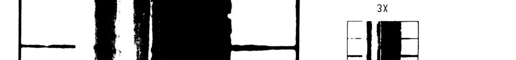
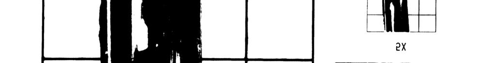
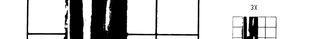
4 CONTENTS Page Paragraph SCOPE Purpose Scope REFERENCED DOCUMENTS Issues of documents DEFINITIONS GENERAL REQUIREMENTS Examination conditions Identification of imperfections Evaluation of imperfections DETAILED REQUIREMENTS Nondestructive tests Rejection of individual O-rings Sampling & 5 FIGURES Figure Backrind, unacceptable, W = 0.070" (1.78 mm).. 9 Backrind, unacceptable, W = 0.103" (2.62 mm).. 10 Backrind, unacceptable, W = 0.103" (2.62 mm).. 11 Backrind, unacceptable, W = 0.103" (2.62 mm).. 12 Backrind, acceptable, W = 0.103" (2.62 mm) Backrind, acceptable, W = 0.103" (2.62 mm) Backrind, unacceptable, W = 0.139" (3.53 mm).. 15 Backrind, acceptable, W = 0.139" (3.53 mm) Backrind, acceptable, W = 0.210" (5.33 mm) Backrind, unacceptable, W = 0.210" (5.33 mm).. 18 Parting line indentation, acceptable, W = 0.070" (1.78 mm) Parting line indentation, acceptable, W = 0.070" (1.78 mm) Parting line indentation, acceptable, W = 0.070" (1.78 mm) Parting line indentation, unacceptable, w = 0.070" (1.78 mm) Parting line indentation, acceptable, W = 0.103" (2.62 mm) Parting line indentation, acceptable, W = 0.103" (2.62 mm) l 24 Parting line indentation, acceptable, W = 0.103" (2.62 mm) Parting line indentation, unacceptable, W = 0.103" (2.62 mm) Parting line indentation, unacceptable, w = 0.139" (3.53 mm) iv
5 MIL -STD-413C CONTENTS (Continued) Page Figure Parting line indentation, unacceptable, w = 0.139" (3.531 mm) Parting line indentation, acceptable, W = 0.139" (3.53 mm) Parting line indentation, unacceptable, w = 0.139" (3.53 mm) Parting line indentation, acceptable, W = 0.210" (5.33 mm) Parting line indentation, unacceptable, w = 0.210" (5.33 mm) Foreign material, acceptable, W " (2.62 mm) Foreign material, unacceptable, W = " (2.62 mm) Foreign material, acceptable, W " (2.62 mm) Foreign material, unacceptable, W = 0.103" (2.62 mm) Foreign material, acceptable, W = 0.139" (3.53 mm) Foreign material, unacceptable, W = " (3.53 mm) Foreign material, acceptable, W = 0.139" (3.53 mm) Foreign material, unacceptable, W = 0.210" (5.33 mm) Foreign material, unacceptable, W = 0.275" (6.98 mm) Excessive trimming, acceptable, W = 0.103" (2.62 mm) Excessive trimming, unacceptable, W = 0.103" (2.62 mm) Excessive trimming, acceptable, W = 0.103" (2.62 mm) Excessive trimming, unacceptable, W = 0.103" (2.62 mm) Excessive trimming, acceptable, W = 0.139" (3.53 mm) Excessive trimming, unacceptable, W = 0.139" (3.53 mm) Excessive trimming, acceptable, W = 0.210" (5.33 mm) Excessive trimming, unacceptable, W = 0.275" (6.98 mm) Excessive flash, unacceptable, W = 0.l03" (2.62 mm) Excessive flash, unacceptable, W = 0.l03" (2.62 mm) v
6 CONTENTS (Continued) Figure Excessive flash, unacceptable, W = 0.103" (2.62 mm) Excessive flash, acceptable, W = 0.103" (2.62 mm) Excessive flash, acceptable, W = 0.139" (3.53 mm) Excessive flash, unacceptable, W = 0.139" (3.53 mm) Excessive flash, acceptable, W = 0.139" (3.53 mm) Excessive flash, unacceptable, W = 0.139" (3.53 mm) Excessive flash, acceptable, W = 0.210" (5.33 mm) Excessive flash, unacceptable, W = 0.275" (6.98 mm) Non-fill, unacceptable, W = 0.070" (1.78 mm). Non-fill, unacceptable, W = 0.103" (2.62 mm). Non-fill, acceptable, W = 0.139" (3.53 mm).. Non-fill, unacceptable, W = 0.139" (3.53 mm). Non-fill, unacceptable, W = 0.139" (3.53 mm). Non-fill, unacceptable, W = 0.210" (5.33 mm). Non-fill, unacceptable, W = 0.210" (5.33 mm). Non-fill, acceptable, W = 0.275" (6.98 mm).. Non-fill, unacceptable, W = 0.275" (6.98 mm). Mold deposit indentations, unacceptable, W = 0.070" (l.78 mm) Mold deposit indentations, acceptable, W = 0.l03" (2.62 mm) Mold deposit indentations, acceptable, W = 0.139" (3.53 mm) Mold deposit indentations, unacceptable, W = 0.139" (3.53 mm) Mold deposit indentations, unacceptable, W = 0.139" (3.53 mm) Mold deposit indentations, unacceptable, W = 0.139" (3.53 mm) Mold deposit indentations, acceptable, W = 0.139" (3.53 mm) Mold deposit indentations, acceptable, W = 0.210" (5.33 mm) Mold deposit indentations, unacceptable, W = 0.275" (6.98 mm) Flow marks, unacceptable, W = 0.070" (1.78 mm) Flow marks, unacceptable, W = 0.139" (3.53 mm) Flow marks, acceptable, W = 0.139" (3.53 mm). Flow marks, unacceptable, W = 0.139" (3.53 mm) Flow marks, acceptable, W = 0.139" (3.53 mm). Flow marks, unacceptable, W = 0.139" (3.53 mm) Flow marks, unacceptable, W = 0.139" (3.53 mm) vi Page
7 CONTENTS (Continued) Page Figure Flow marks, acceptable, W = 0.139" (3.53 mm).. 85 Flow marks, acceptable, W = 0.210" (5.33 mm).. 86 Off-register and/or mismatch, unacceptable, w = 0.070" (1.78 mm) Off-register and/or mismatch, unacceptable, w = 0.103" (2.62 mm) Off-register and/or mismatch, unacceptable, w = 0.139" (3.53 mm) Off-register and/or mismatch, acceptable, w = 0.139" (3.53 mm) Off-register and/or mismatch, acceptable, w= 0.139" (3.53 mm) Off-register and/or mismatch, acceptable, w = 0.139" (3.53 mm) Off-register and/or mismatch, acceptable, w = 0.210" (5.33 mm) Off-register and/or mismatch, unacceptable, w = 0.210" (5.33 mm) Supplementary illustrations of surface imperfections TABLES Table I. II. III. Index to photographs of representative acceptable and unacceptable surface imperfections.. 6 Quantitative classification of imperfections, maximum acceptable dimensions in inches Quantitative classification of imperfections, maximum acceptable dimensions in millimeters. 8 vii/viii
8
9 1. SCOPE 1.1 Purpose. The objective of this standard is to assure acquisition of elastomeric O-rings with a surface quality level adequate for their intended use. To achieve this objective, this standard: (a) (b) Includes illustrations and supplementary definitions and dimensions to identify O-ring surface imperfections for the purpose of inspection, and Establishes quantitative levels of acceptance for O-rings relative to surface imperfections, type, size and quantity In general, this standard is intended to supplement the inspection procedure of a particular specification for O-rings. Where no such procedure is provided, this standard becomes the primary guide. In the event of conflict between this standard and the inspection procedure of an end item specification or a specification for O-rings, the basic specification shall govern. 1.2 Scope. This document covers only visible imperfections of O-rings. 2. REFERENCED DOCUMENTS 2.1 Issues of documents. The following documents, of the issue in effect on date of invitation for bids or request for proposal, form a Part of this standard to the extent specified herein. STANDARDS MILITARY MIL-STD-105 MIL-STD Sampling Procedures and Tables for Inspection by Attributes. - Quality Assurance Terms and Definitions. (Copies of specifications, standards, drawings, and publications required by contractors in connection with specific acquisition functions should be obtained from the contracting activity or as directed by the contracting officer.) 3. DEFINITIONS 3.1 MIL-STD-105 and MIL-STD-109 define critical, major and minor defects. The classification of an O-ring defect as "critical" requires knowledge of the end use; therefore, critical defects are not included in this standard but must be, considered in the basic specification(s). O-rings inspected for surface imperfections in accordance with this standard are determined to be either acceptable or unacceptable. The concept of minor defects is not applicable. 1
10 3.2 The imperfections (a) (b) (c) (d) (e) (f) (g) (h) (i) (j) (k) (1) following word descriptions apply to the visible covered in this standard: Backrind. A longitudinal recess of wide angle U-like or W-like cross-sections, oriented circumferentially and located at parting lines, caused by thermal expansion over sharp mold edge or by premature cure. Blister. A void or a hole in the body of the O-ring, which may or may not cause protrusion on the surface and may be covered or open, caused by air being trapped during cure. Bloom. Material which has migrated from the body of the O-ring to the O-ring surface. Excessive trimming. Flat spots or nicks, producing out-oftolerance cross-section, caused by excessive buffing or trimming of flash. An O-ring is considered excessively trimmed only if a flat area results to the extent that an out-of-tolerance condition exists. Even when an O-ring has not been "excessively trimmed", it could have an imperfect trim or buff condition. "limperfect trim or buff" is a condition, wherein abrasion, scuffing or tearing, generated when removing flash or parting line projection, result in a substantially coarser texture. Protruding O-ring material or a heavily abraded surface are the indicators of "imperfect trim" and are not acceptable on any size O-ring. Flash. Very thin gage, sometimes film-like, material which extends from parting line projection, resulting from mold separation or inadequate trim. Flow mark. A thread-like recess, usually curved, of very slight depth in the unflexed state, with normal surface texture and radiused edge. It is caused by incomplete flow and knit of the material. Foreign material. Any extraneous, embedded matter (such as contamination, dirt, or undispersed pigment) or depression, formed by its removal. Mismatch. The cross-sectional radius in one ring half is unequal to that of the other half. It is caused by the dimensional difference in mold halves. Mold deposit indentations. Surface indentations, irregular in shape, with rough surface texture, caused by a build-up of hardened deposits, adhering to the mold cavity. Non-fill. A randomly spaced, irregularly shaped, surface indentation, having a coarser texture, than the normal O-ring surface. Off-register. Misaligned O-ring halves, caused by the lateral shift of one mold cavity plate, relative to the other. Parting line indentation. A shallow, saucer-like recess, located on the parting line, caused by a deformity in mold edge. 2
11 (m) Parting line projection. A continuous ridge of material, situated on the parting line, caused by worn or otherwise excessively rounded mold edges. (n) Porosity. Presence of numerous minute voids or sponginess, showing up usually in a cross-section cut. 4. GENERAL REQUIREMENTS 4.1 Examination conditions. The illumination during examination shall be 400-foot candles, minimum. Bloom or surface dust, if present on the O-ring, shall be removed before inspection. 4.2 Identification of imperfections Enlarged photographs of representative, acceptable and unacceptable imperfections are included to aid inspection (see figures 1 through 86). The grid sizes are 0.1, 0.2, 0.3, 0.5 and 1.0 inch for lx, 2x, 3x, 5x, and 10X magnification, respectively Arrows have been added to selected 10X magnification photographs for aid in identifying the imperfection shown. 3X power magnification, however, shall be used to aid in the detection of imperfections, unless otherwise specified by the contract All photographs are indexed in table I, according to figure number, O-ring size (W), type of imperfection and classification of imperfection (acceptable and unacceptable). For some types of imperfections, exaggerated line drawings are included to supplement the photographs and to illustrate the nature of the imperfections more vividly (see figure 87) It should be borne in mind that this standard has included photographs of only the most common imperfections that occur during the fabrication of elastomeric O-rings. It is not feasible to obtain photographs to show clearly all possible imperfections in all sizes. Further, the definitions of imperfections in this standard do not abrogate requirements of a particular specification, contract or order. Where other types of imperfections such as cracks or ruptures are found, the general workmanship criteria of 5.1 shall govern. 4.3 Evaluation of imperfections For the purpose of visual examination, it is recommended that inspectors use, for reference and comparison, wire gauges or other type devices in diameters of 0.002; 0.005; 0.010: 0.015; and inch (or 0.05; 0.13; 0.25; 0.38; and 0.51 millimeters (mm)). Such gauges shall be positioned adjacent to imperfections for their size determination Quantitative classification of acceptable and unacceptable imperfections is shown in table II (showing dimensions in inches) and in table III (showing dimensions in mm). When any dimension of an imperfection exceeds the value specified in tables II or III, as applicable, this constitutes an unacceptable imperfection for any O-ring having a crosssectional width, "W", within the range shown. Otherwise, the imperfection 3
12 8 December 1900 is classified as acceptable. In general, the dimensional limits of imperfections are related to the O-ring cross-sectional width. For O-ring sizes appreciably larger than inch (6.98 mm) cross-sectional width, quality asurance personnel should refer to the particular specification involved for quantitative dimensional limits of imperfections. 5. DETAILED REQUIREMENTS 5.1 Nondestructive tests. In all cases, including where a conflict exists with this standard, the requirements of the applicable specification shall govern. Workmanship and finish shall be in acordance with the highest grade practice in manufacturing this kind of product. Manufacturing practices shall be such that the physical properties of the finished product shall be uniform in quality and condition, clean, smooth and free from cracks, ruptures, porosity, blisters, foreign materials or other imperfections detrimental to the performance of the parts, as further defined herein Each O-ring sampled shall be carefully examined for visible surface imperfection s (see section 4, and tables I, II, and III). Unacceptable imperfections (those which exceed the dimensional limits in tables II and 111, as applicable, or those described in 5.2), shall be cause for rejection of O-rings. 5.2 Rejection of individual O-rings. Rejection of individual O-rings shall be based on the following: (a) Each O-ring found to have out-of-tolerance dimensions shall be rejected. (b) Visual surface imperfections shall be cause for rejection, as follows: Any O-ring with one or more unacceptable surface imperfection. Any O-ring with radially oriented flow mark, regardless of length. Any O-ring exhibiting poor general appearance, as defined in 5.1. Such rejection applies equally to surface imperfections found on O-rings inspected for any requirement under the applicable specification. Also, any O-ring which was part of a sample shall be rejected if it contains one or more unacceptable imperfections, regardless of whether its lot or batch as a whole is accepted or rejected. 5.3 Sampling. All O-rings shall be subjected to one or more MIL-STD-105 sampling procedures, as specified by the contracting activity, except where the material specification includes a sampling plan. Unless specified otherwise in the material specification, purchase order or 4
13 contract, an Acceptable Quality Level (AQL) of 1.5 percent defective shall used. Acceptance or rejection of the lot, sub lot or batch shall be on this basis, except where already rejected in 5.1. In the application of MIL-STD-105 to this standard, the following shall be noted: (a) (b) Inasmuch as inspection to this standard is to determine whether O-rings are either acceptable or unacceptable and in view of 3.1, minor and critical defects do not apply. Any sampled O-ring which is rejectable, as indicated in 5.2, shall be considered defective for the determination of the acceptance or rejection of the lot it represents. Custodians : Preparing activity: Army -MI Navy - SH Navy - SH (Project ) Air Force - 99 Review activities: Navy - OS, AS Air Force - 11 User activities: Army - AT Navy - MC
14 6
15 7

16 NOTE: Length and width of an imperfection are synonymous except for backrind, parting line projection, excessive flash and flow marks. O-ring cross-sectional width "W" Less than to to to and over TABLE III. Quantitative classification of imperfections. maximum acceptable dimensions in millimeters. O-ring cross-sectional width W Backrind Parting line indentations Foreign material Parting line projection and excessive flash Non-fill Mold deposit indentations Flow marks Offregister and/or mismatch 8 Less than to to to and over Depth Width 0 I Depth Width Depth Width o I I Max. ht Depth Width I o Depth Width 1 I Depth Width Max Dimensions of imperfections are acceptable unless they exceed the values specified in the table.
17 Figure 1 - Backrind, unacceptable, W = 0.070" (1.78 mm.) 9
18 Figure 2 - Backrind, unacceptable, W = 0.103" (2.62mm.) 10
19 Figure 3 - Backrind, unacceptable, W = 0.103" (2.62 mm.) 11
20 Figure 4 - Backrind, unacceptable, W = 0.103" (2.62 mm.) 12
21 Figure 5 - Backrind, acceptable, W = 0.103" (2.62 mm.) 13
22 Figure 6 - Backrind, acceptable, W = 0.103" (2.62 mm.) 14
23 Figure 7 - Backrind, unnacceptable, W = 0.139" (3.53 mm.) 15
24 Figure 8 - Backrind, acceptable, W = 0.139" (3.53 mm.) 16


25 Figure 9 - Backrind, acceptable, W= (5.33 mm.) 17
26 Figure 10 - Backrind, unacceptable, W = 0.210" (5.33 mm.) 18
27 Figure 11 - Parting line indentation, acceptable, W = 0.070" (1.78 mm.) 19
28 Figure 12 - Parting line indentation, acceptable, W = 0.070" (1.78 mm.) 20
29 Figure 13 - Parting line indentation, acceptable, W = 0.070" (1.78 mm.) 21
30 Figure 14 - Parting line indentation, unacceptable, W = 0.070" (1.78 mm.) 22
31 Figure 15 - Parting line indentation, acceptable, W = 0.103" (2.62 mm.) 23
32 Figure 16 - Parting line indentation, acceptable, W = 0.103" (2.62 mm.) 24
33 Figure 17 - Parting line indentation, acceptable, W = 0.103" (2.62 mm.) 25
34 Figure 18 - Parting line indentation, unacceptable, W = 0.103" (2.62 mm.) 26
35 Figure 19 - Parting line indentation, unacceptable, W = 0.139" (3.53 mm.) 27
36 Figure 20 - Parting line indentation, unacceptable, W = 0.139" (3.53 mm.) 28
37 Figure 21 - Parting line indentation, acceptable, W = 0.139" (3.53 mm.) 29
38 Figure 22 - Parting line indentation, unacceptable, W = 0.139" (3.53 mm.) 30
39 Figure 23 - Parting line indentation, acceptable, W = 0.210" (5.33 mm.) 31
40 Figure 24 - Parting line indentation, unacceptable, W = 0.210" (5.33 mm.) 32
41 Figure 25 - Foreign material, acceptable, W = 0.103" (2.62 mm.) 33
42 Figure 26 - Foreign material, unacceptable, W = 0.103" (2.62 mm.) 34
43 Figure 27 - Foreign material, acceptable, W = 0.103" (2.62 mm.) 35
44 Figure 28 - Foreign material, unacceptable, W = 0.103" (2.62 mm.) 36
45 Figure 29 - Foreign material, acceptable, W = 0.139" (3.53 mm.) 37
46 Figure 30 - Foreign material, unacceptable, W = 0.139" (3.53 mm.) 38
47 Figure 31 - Foreign material, acceptable, W = 0.139" (3.53 mm.) 39
48 Figure 32 - Foreign material, unacceptable, W = 0.210" (5.33 mm.) 40


49 Figure 33 - Foreign material, unacceptable, W = 0.275" (6.98 mm.) 41
50 Figure 34 - Excessive trimming, acceptable, W = 0.103" (2.62 mm.) 42
51 Figure 35 - Excessive trimming, unacceptable, W = 0.103" (2.62 mm.) 43
52 Figure 36 - Excessive trimming, acceptable, W = 0.103" (2.62 mm.) 44
53 Figure 37 - Excessive trimming unacceptable, W = 0.103" (2.62 mm.) 45
54 Figure 38 - Excessive trimming, acceptable, W = 0.139" (3.53 mm.) 46
55 Figure 39 - Excessive trimming, unacceptable, W = 0.139" (3.53 mm.) 47
56 Figure 40 - Excessive trimming, acceptable, W = 0.210" (5.33 mm.) 48
57 Figure 41 - Excessive trimming, unacceptable, w= (6.98 mm.) 49
58 Figure 42 - Excessive flash, unacceptable, W = 0.103" (2.62 mm.) 50
59 MIL-STD-413c Figure 43 - Excessive flash, unacceptable, W = 0.103" (2.62 mm.) 51
60 Figure 44 - Excessive flash, unacceptable, W = 0.103" (2.62 mm.) 52
61 Figure 45 - Excessive flash, acceptable, W = 0.103" (2.62 mm.) 53
62 Figure 46 - Excessive flash, acceptable, W = 0.139" (3.53 mm.) 54
63 Figure 47 - Excessive flash, unacceptable, W = 0.139" (3.53 mm.) 55
64 Figure 48 - Excessive flash, acceptable, W = 0.139" (3.53 mm.) 56
65 Figure 49 - Excessive flash, unacceptable, W = 0.139" (3.53 mm.) 57
66 Figure 50 - Excessive flash, acceptable, W = 0.210" (5.33 mm.) 58
67 Figure 51 - Excessive flash, unacceptable, W = (6.98 mm.) 59
68 Figure 52 - Non-fill, unacceptable, W = 0.070" (1.78 mm.) 60
69 Figure 53 - Non-fill,unacceptable, W= (2.62 m.) 61
70 Figure 54 - Non-fill, acceptable, W = 0.139" (3.53 mm.) 62


71 Figure 55 - Non-fill,unacceptable, W= (3.53 mm.) 63
72 Figure 56 - Non-fill, unacceptable, W = 0.139" (3.53 mm.) 64
73 Figure 57 - Non-fill, unacceptable, W = 0.210" (5.33 mm.) 65
74 Figure 58 - Non-fill, unacceptable, W = 0.210" (5.33 mm.) 66

75 Figure 59 - Non-fill, acceptable, W = 0.275" (6.98 mm.) 67

76 Figure 60 - Non-fill, unacceptable, W = 0.275" (6.98 mm.) 68
77 Figure 61 - Mold deposit indentations, unacceptable, W= (1.78 mm) 69
78 Figure 62 - Mold deposit indentations, acceptable, W = 0.103" (2.62 mm.) 70

79 Figure 63 - Mold deposit indentations, acceptable, w= (3.53 mm.) 71
80 Figure 64 - Mold deposit indentations, unacceptable, W = 0.139" (3.53 mm.) 72
81 Figure 65 - Mold deposit indentations, unacceptable, W = 0.139" (3.53 mm.) 73
82 Figure 66 - Mold deposit indentations, unacceptable, W = 0.139" (3.53 mm.) 74
83 Figure 67 - Mold deposit indentations, acceptable, W = 0.139" (3.53 mm.) 75
84 Figure 68 - Mold deposit indentations, acceptable, W = 0.210" (5.33 mm.) 76
85 Figure 69 - Mold deposit indentations, unacceptable, W = 0.275" (6.98 mm.) 77
86 Figure 70 - Flow marks, unacceptable, W = 0.070" (1.78 mm.) 78

87 Figure 71 - Flow marks, unacceptable, W = 0.139" (3.53 mm.) 79
88 Figure 72 - Flow marks, acceptable, W = 0.139" (3.53 mm.) 80


89 Figure 73 - Flow marks, unacceptable, W= (3.53 mm.) 81
90 Figure 74 - Flow marks, acceptable, W = 0.139" (3.53 mm.) 82
91 Figure 75 - Flow marks, unacceptable, W= (3.53 mm.) 83
92 Figure 76 - Flow marks, unacceptable, W = 0.139" (3.53 mm.) 84
93 Figure 77 - Flow marks, acceptable, W = 0.139" (3.53 mm.) 85
94 Figure 78 - Flow marks, acceptable, W = 0.210" (5.33 mm.) 86
95 Figure 79 - Off-register and/or mismatch, unacceptable, W = 0.070" (1.78 mm.) 87
96 Figure 80 - Off-register and/or mismatch, unacceptable, W = 0.103" (2.62 mm.) 88
97 Figure 81 - Off-register and/or mismatch, unacceptable, W = 0.139" (3.53 mm.) 89
98 Figure 82 - Off-register and/or mismatch, acceptable, W = 0.139" (3.53 mm.) 90
99 Figure 83 - Off-register and/or mismatch, acceptable, W = 0.139" (3.53 mm.) 91
100 Figure 84 - Off-register and/or mismatch, acceptable, W = 0.139" (3.53 mm.) 92
101 Figure 85 - Off-register and/or mismatch, acceptable, W = 0.210" (5.33 mm.) 93
102 Figure 86 - Off-register and/or mismatch, unacceptable, W = 0.210" (5.33 mm.) 94
103 Figure 87 - Supplementary illustrations of surface imperfections. 95/96 * U.S. GOVERNMENT PRINTING OFFICE:
104
105


106 主营业务范围 :ASTM NAS NASM MIL ISO EN DIN 等技术标准翻译 ; 技术资料翻译 ; 国外技术标准中文版代购 业务 QQ: 专业 诚信 专注于技术翻译 质量不满意, 可不付款
Downloaded from
 NOTE: has been redesignated as a Test Method Standard. The cover page has been changed for Administrative reasons. There are no other changes to this Document. 15 FEBRUARY 1957 SUPERSEDING NAVSHIPS 250-344-7
DETAIL SPECIFICATION VALVES, EXPANSION, THERMOSTATIC, REFRIGERANT-12 (R-12) AND REFRIGERANT-22 (R-22) Inactive for new design after 1 April 1996.
 AND REFRIGERANT-22 (R-22) Inactive for new design after 1 April 1996.") [INCH-POUND] MIL-DTL-23450E 7 September 2016 SUPERSEDING MIL-DTL-23450D w/amendment 1 18 January 2011 DETAIL SPECIFICATION VALVES, EXPANSION, THERMOSTATIC, REFRIGERANT- (R-) AND REFRIGERANT-22 (R-22) Inactive
[INCH-POUND] MIL-DTL-23450E 7 September 2016 SUPERSEDING MIL-DTL-23450D w/amendment 1 18 January 2011 DETAIL SPECIFICATION VALVES, EXPANSION, THERMOSTATIC, REFRIGERANT- (R-) AND REFRIGERANT-22 (R-22) Inactive
MIL-STD-883H METHOD EXTERNAL VISUAL
 * EXTERNAL VISUAL 1. PURPOSE. The purpose of this test method is to verify the workmanship of hermetically packaged devices. This test method shall also be utilized to inspect for damage due to handling,
DETAIL SPECIFICATION HOSE ASSEMBLIES, ELASTOMERIC HYDRAULIC FLUID, FUEL, AND OIL RESISTANT, GENERAL SPECIFICATION FOR
 INCH-POUND MIL DTL 8795E 22 September 2000 SUPERSEDING MIL H 8795D 14 October 1985 DETAIL SPECIFICATION HOSE ASSEMBLIES, ELASTOMERIC HYDRAULIC FLUID, FUEL, AND OIL RESISTANT, GENERAL SPECIFICATION FOR
MILITARY STANDARD INTERFACE STANDARD FOR SHIPBOARD SYSTEMS SECTION 106 COMPRESSED AIR SERVICE FOR SURFACE SHIPS
 SUPERSEDING SECTION 106A 19 April 1973 (See 9.2) MILITARY STANDARD INTERFACE STANDARD FOR SHIPBOARD SYSTEMS SECTION 106 COMPRESSED AIR SERVICE FOR SURFACE SHIPS AMSC N/A FSC 1990 DISTRIBUTION STATEMENT
MILITARY SPECIFICATION SHEET SCREW, MACHINE, PAN HEAD, CROSS-RECESSED, CORROSION RESISTANT STEEL, UNC-2A
 INCH-POUND MS19D April 199 Superseding MS19C 18 July 198 MILITARY SPECIFICATION SHEET SCREW, MACHINE, PAN HEAD, CROSS-RECESSED, CORROSION RESISTANT STEEL, UNC-A This specification is approved for use by
MILITARY SPECIFICATION. CARTRIDGE 5.56mm, BALL, M855. MIL-C-63989C was inactivated after 15 September 1996 For New Design.
 INCH-POUND MIL-C-63989C (AR) 30 January 2001 SUPERSEDING AMENDMENT 3 15 October 1999 MILITARY SPECIFICATION CARTRIDGE 5.56mm, BALL, M855 MIL-C-63989C was inactivated after 15 September 1996 For New Design.
PERFORMANCE SPECIFICATION PROPELLANT, HYDROGEN
 METRIC 17 May 2013 SUPERSEDING MIL-PRF-27201D 07 February 2007 PERFORMANCE SPECIFICATION PROPELLANT, HYDROGEN This specification is approved for use by all Departments and Agencies of the Department of
FEDERAL SPECIFICATION ACETYLENE, TECHNICAL, DISSOLVED
 METRIC 27 December 2010 SUPERSEDING BB-A-106C 30 January 2001 FEDERAL SPECIFICATION ACETYLENE, TECHNICAL, DISSOLVED The General Services Administration has authorized the use of this federal specification
DEPARTMENT OF DEFENSE TEST METHOD STANDARD METHOD 215, RESISTANCE TO SOLVENTS
 INCH-POUND MIL-STD-202-215 18 April 2015 SUPERSEDING MIL-STD-202G w/change 2 (IN PART) 28 June 2013 (see 6.1) DEPARTMENT OF DEFENSE TEST METHOD STANDARD METHOD 215, RESISTANCE TO SOLVENTS AMSC N/A FSC
DEPARTMENT OF DEFENSE TEST METHOD STANDARD METHOD 215, RESISTANCE TO SOLVENTS
 INCH-POUND MIL-STD-202-215 4 May 2018 SUPERSEDING MIL-STD-202-215 18 April 2015 DEPARTMENT OF DEFENSE TEST METHOD STANDARD METHOD 215, RESISTANCE TO SOLVENTS AMSC N/A FSC 59GP FOREWORD 1. This standard
PERFORMANCE SPECIFICATION PROPELLANT PRESSURIZING AGENT, ARGON
 METRIC 07 August 2013 SUPERSEDING MIL-PRF-27415B 08 February 2007 PERFORMANCE SPECIFICATION PROPELLANT PRESSURIZING AGENT, ARGON Comments, suggestions, or questions on this document should be addressed
O-RINGS. ! Description and advantages
 O-INGS! Description and advantages The O-ing is the most simple, universal and cost-effective seal of the market. Its simple design (Figure 1) and its widespread use has enabled the development of large-scale
COMMERCIAL ITEM DESCRIPTION NITROGEN, TECHNICAL
 METRIC 3 March 2011 SUPERSEDING A-A-59503B 20 October 2008 COMMERCIAL ITEM DESCRIPTION NITROGEN, TECHNICAL The General Services Administration has authorized the use of this commercial item description
DETAIL SPECIFICATION FUZE, POINT DETONATING - M739A1. Inactive for new design after 30 September 2007
 INCH-POUND 17 December 2012 SUPERSEDING w/amendment 1 30 April 2012 DETAIL SPECIFICATION FUZE, POINT DETONATING - M739A1 Inactive for new design after 30 September 2007 This specification is approved for
A-A June 2000 SUPERSEDING BB-N-411C 3 January 1973 COMMERCIAL ITEM DESCRIPTION NITROGEN, TECHNICAL
 METRIC 1 June 2000 SUPERSEDING BB-N-411C 3 January 1973 COMMERCIAL ITEM DESCRIPTION NITROGEN, TECHNICAL The General Service Administration has authorized the use of this commercial item description by
GGG-M-125/3A September 20, 1982 SUPERSEDING GGG-M-125/3 March 28, 1975 FEDERAL SPECIFICATION
 September 20, 1982 SUPERSEDING GGG-M-125/3 March 28, 1975 FEDERAL SPECIFICATION RESPIRATOR ASSEMBLIES: AIR LINE, WITH DISPOSABLE HOOD (SUPPLIED AIR) This specification was approved by the Commissioner,
MILITARY SPECIFICATION POWDER, BLACK
 INCH-POUND 2 October 1998 SUPERSEDING AMENDMENT 1 10 June 1997 MILITARY SPECIFICATION POWDER, BLACK This Amendment forms a part of Military Specification dated 5 February 1993, and is approved for use
Rubber Dock Hose care, Use & Maintenance
 Rubber Dock Hose care, Use & Maintenance Prepared by: Thomas J. Wise VP Corporate Development Contents Revised - July. 2014 1. Novaflex Rubber Dock Hose Testing & Inspection Program 1.1 Introduction -
DETAIL SPECIFICATION VALVES, ANGLE, PRESSURE RELIEF, NAVAL SHIPBOARD, FOR STEAM SERVICE
 INCH-POUND 7 December 2016 SUPERSEDING MIL-V-20065D(SHIPS) 8 June 1967 DETAIL SPECIFICATION VALVES, ANGLE, PRESSURE RELIEF, NAVAL SHIPBOARD, FOR STEAM SERVICE This specification is approved for use by
PERFORMANCE SPECIFICATION SHEET MICROPHONE ASSEMBLY, M-169A/AIC
 PERFORMANCE SPECIFICATION SHEET INCH-POUND MIL-PRF-26542/12C 12 September 2012 SUPERSEDING MIL-PRF-26542/12B 11 February 1999 MICROPHONE ASSEMBLY, M-169A/AIC This specification sheet is approved for use
TECH TIPS: ROPE DEFECTS
 Hoist Ropes: Why must they be inspected? A hoist rope is not made to last forever. This is a useful fact, as the kinds of wear that appear on a rope can indicate areas of problems within an installation
Courtesy of Loos & Co., Inc.
 INCH-POUND 22 December 2015 SUPERSEDING RR-W-410G 24 June 2010 FEDERAL SPECIFICATION WIRE ROPE AND STRAND The General Services Administration has authorized the use of this federal specification by all
DETAIL SPECIFICATION HOSE AND HOSE ASSEMBLIES, RUBBER, HYDRAULIC PRESSURE TYPE, GENERAL SPECIFICATION FOR
 INCH-POUND 4 December 2008 SUPERSEDING MIL-DTL-52471E 27 April 1998 DETAIL SPECIFICATION HOSE AND HOSE ASSEMBLIES, RUBBER, HYDRAULIC PRESSURE TYPE, GENERAL SPECIFICATION FOR This specification is approved
FEDERAL SPECIFICATION WIRE ROPE AND STRAND
 INCH-POUND 6 December 2007 SUPERSEDING RR-W-410E 7 February 2002 FEDERAL SPECIFICATION WIRE ROPE AND STRAND The General Services Administration has authorized the use of this federal specification by all
Product Standard and Inspection Criteria for ilmasil PS Clear Fused Quartz Tubes
 Product Standard and Inspection Criteria for Page 1 of 5 Version S-101-13 Index: C (June 2015) Application: This standard is applicable to direct drawn tubes produced with ilmasil PS base material 1 Optical
SPECIFICATION FOR RAISED PAVEMENT MARKERS
 SPECIFICATION FOR RAISED PAVEMENT MARKERS 1. SCOPE This specification covers performance requirements of retroreflective and nonretroreflective raised pavement markers which are bonded directly to the
Visual Inspection of Medicinal Products for Parenteral Use
 Good Practice Paper Visual Inspection of Medicinal Products for Parenteral Use Version 1.0 (September 2014) Version 1.0 1 (16) Acknowledgement This ECA Good Practice Paper was developed by the Steering
DETAIL SPECIFICATION HOSE, AIRCRAFT, LOW PRESSURE AIR AND VACUUM, FLEXIBLE
 INCH-POUND 1 May 2018 SUPERSEDING w/amendment 1 19 January 2010 DETAIL SPECIFICATION HOSE, AIRCRAFT, LOW PRESSURE AIR AND VACUUM, FLEXIBLE This specification is approved for use by all Departments and
COMPRESSION SET Description: The seal exhibits a flat-sided cross-section, the flat sides correspoding to the mating seal surfaces.
 Bentwood, NH (603) 678-9610 ABRASION Description: The seal or parts of the seal exhibit a flat surface parallel to the direction or motion. Loose particles and scrapes may be found on the seal surface.
PERFORMANCE SPECIFICATION VALVE; AIRCRAFT, PNEUMATIC, HIGH-PRESSURE CHARGING
 INCH-POUND 16 October 2012 SUPERSEDING MIL-PRF-6164F 10 October 1998 PERFORMANCE SPECIFICATION VALVE; AIRCRAFT, PNEUMATIC, HIGH-PRESSURE CHARGING This specification is approved for use by all Departments
SECTION 2 HILLTOPPER MOUND AND HOMEPLATE CLAY BASEBALL APPLICATIONS. 1. Hilltopper Mound Clay for baseball pitching mound or homeplate areas
 Stabilizer Solutions, Inc. 33 South 28 th St. Phoenix, AZ 85034 800-336-2468 (Fax) 602-225-5902 stabilizersolutions.com info@stabilizersolutions.com SECTION 2 HILLTOPPER MOUND AND HOMEPLATE CLAY BASEBALL
Installation Instructions For Flat Seated Bolted Type RAH Series Disk Holders
 Installation Instructions For Flat Seated Bolted Type RAH Series Disk Holders RA Series Rupture Disks 1. WARNING a) Read the complete instructions before attempting to install the rupture disk and holder
DEFENSE LOGISTICS AGENCY LAND AND MARITIME P.O. BOX 3990 COLUMBUS, OHIO
 DEFENSE LOGISTICS AGENCY LAND AND MARITIME P.O. BOX 3990 COLUMBUS, OHIO 43218-3990 January 6, 2016 MEMORANDUM FOR VAI (LSA) SUBJECT: Dated Engineering Practices Study To Solicit User Input To Determine
DETAIL SPECIFICATION. HOSE, RUBBER, HYDRAULIC, HIGH PRESSURE 3,000 PSI, OPERATING TEMPERATURE RANGE -65 F to +160 F
 INCH-POUND MIL-DTL-8788G 24 May 2017 SUPERSEDING MIL-DTL-8788G 11 May 2015 DETAIL SPECIFICATION HOSE, RUBBER, HYDRAULIC, HIGH PRESSURE 3,000 PSI, OPERATING TEMPERATURE RANGE -65 F to +160 F This specification
Illinois Association of Vocational Agricultural Teachers Poultry Career Development Event
 A. GENERAL INFORMATION 1. Eligibility Illinois Association of Vocational Agricultural Teachers Poultry Career Development Event Any student is eligible who is under 21 years of age at the time of the event,
PERFORMANCE SPECIFICATION HARNESS AND CABLE ASSEMBLIES
 METRIC 26 July 1996 SUPERSEDING MIL-H-62540(AT) 15 June 1987 PERFORMANCE SPECIFICATION HARNESS AND CABLE ASSEMBLIES This specification is approved for use by the U.S. Army Tank-automotive and Armaments
NAVSEA STANDARD ITEM. 2.2 T9074-AS-GIB-010/271, Requirements for Nondestructive Testing Methods
 NAVSEA STANDARD ITEM ITEM NO: 009-53 DATE: 29 JUL 2011 CATEGORY: II 1. SCOPE: 1.1 Title: Bolted Bonnet Steam Valve; repair (shop) 2. REFERENCES: 2.1 S9086-CJ-STM-010/CH-075, Fasteners 2.2 T9074-AS-GIB-010/271,
Standard Practice for Eddy-Current Examination of Steel Tubular Products Using Magnetic Saturation 1
 Designation: E 309 95 An American National Standard Standard Practice for Eddy-Current Examination of Steel Tubular Products Using Magnetic Saturation 1 This standard is issued under the fixed designation
SPECIFICATIONS - DETAILED PROVISIONS Section Butterfly Valves C O N T E N T S
 SPECIFICATIONS - DETAILED PROVISIONS Section 15103 - Butterfly Valves C O N T E N T S PART 1 - GENERAL... 1 1.01 REQUIREMENT... 1 1.02 VALVE MANUFACTURER... 1 1.03 GUARANTEE... 1 PART 2 - PRODUCT... 1
COMMERCIAL ITEM DESCRIPTION TORCHES, OXYACETYLENE, HAND HELD, CUTTING AND WELDING
 INCH-POUND 2 July 2010 SUPERSEDING A-A-55826 5 September 1996 COMMERCIAL ITEM DESCRIPTION TORCHES, OXYACETYLENE, HAND HELD, CUTTING AND WELDING The General Services Administration has authorized the use
EXPIRATION DATE: (FOR RENEWAL, SEE 49 CFR ) 1. GRANTEE: Structural Composites Industries (SCI) Pomona, CA
 1. GRANTEE: Structural Composites Industries (SCI) Pomona, CA") East Building, PHH-30 1200 New Jersey Avenue S.E. U.S. Department of Transportation Washington, D.C. 20590 Pipeline and Hazardous Materials Safety Administration DOT-SP 13583 (NINTH REVISION) EXPIRATION
East Building, PHH-30 1200 New Jersey Avenue S.E. U.S. Department of Transportation Washington, D.C. 20590 Pipeline and Hazardous Materials Safety Administration DOT-SP 13583 (NINTH REVISION) EXPIRATION
PERFORMANCE SPECIFICATION PROPELLANT, OXYGEN
 METRIC 21 November 2006 SUPERSEDING MIL-PRF-25508F 19 October 1995 PERFORMANCE SPECIFICATION PROPELLANT, OXYGEN This specification is approved for use by all Departments and Agencies of the Department
DETAIL SPECIFICATION HOSE, RUBBER, AIRCRAFT, FUEL, OIL, COOLANT, WATER, AND ALCOHOL
 INCH-POUND 20 September 2007 SUPERSEDING MIL-DTL-6000C 10 December 1998 DETAIL SPECIFICATION HOSE, RUBBER, AIRCRAFT, FUEL, OIL, COOLANT, WATER, AND ALCOHOL This specification is approved for use by all
PERFORMANCE SPECIFICATION VALVES, CHECK, MINIATURE, HYDRAULIC, AIRCRAFT AND MISSILE
 INCH-POUND MIL-PRF-25675C 26 NOVEMBER 1997 SUPERSEDING (See 6.8) PERFORMANCE SPECIFICATION VALVES, CHECK, MINIATURE, HYDRAULIC, AIRCRAFT AND MISSILE This specification is approved for use by the Department
PERFORMANCE SPECIFICATION FILTER ELEMENTS, DISPOSABLE, FLUID PRESSSURE, HYDRAULIC LINE, 5 MICRON ABSOLUTE
 INCH-POUND 24 July 2013 SUPERSEDING MIL-PRF-83860C(USAF) 31 January 1998 PERFORMANCE SPECIFICATION FILTER ELEMENTS, DISPOSABLE, FLUID PRESSSURE, HYDRAULIC LINE, 5 MICRON ABSOLUTE Comments, suggestions,
RESISTANCE OF COMPACTED ASPHALT MIXTURE TO MOISTURE INDUCED DAMAGE (Kansas Test Method KT-56)
") 5.9.56 RESISTANCE OF COMPACTED ASPHALT MIXTURE TO MOISTURE INDUCED DAMAGE (Kansas Test Method ) 1. SCOPE This test covers preparation of specimens and measurement of the change of tensile strength resulting
5.9.56 RESISTANCE OF COMPACTED ASPHALT MIXTURE TO MOISTURE INDUCED DAMAGE (Kansas Test Method ) 1. SCOPE This test covers preparation of specimens and measurement of the change of tensile strength resulting
PERFORMANCE SPECIFICATION VALVE; AIRCRAFT, PNEUMATIC, HIGH-PRESSURE CHARGING
 INCH-POUND 10 October 1998 SUPERSEDING MIL-V-6164E 15 June 1990 1. SCOPE PERFORMANCE SPECIFICATION VALVE; AIRCRAFT, PNEUMATIC, HIGH-PRESSURE CHARGING This specification is approved for use by all Departments
CLASS D - SENSITIVE LEAK TEST GAS AND BUBBLE METHOD. 1.1 To provide definitive requirements for PNEUMATIC pressure testing of piping systems.
 Page 1 of 7 CLASS D - SENSITIVE LEAK TEST GAS AND BUBBLE METHOD 1. SCOPE 1.1 To provide definitive requirements for PNEUMATIC pressure testing of piping systems. 1.2 The piping system as used herein is
BARRIER OFFSET 0" A 6" 6" A 12" 12" A 26" A 26" 3A OR 4A L OR S * ** L OR S L OR S
 ACCEPTABLE (TCB) TYPES AND ANCHORING DETAILS BASED ON UNDERLYING SURFACE TYPE AND BARRIER OFFSET FROM DROP-OFF BARRIER OFFSET UNDERLYING SURFACE 0" A 6" 6" A 12" 12" A 26" A 26" TCB TYPE DETAIL TCB TYPE
DETERMINATION OF THE DEPTH OF CLOSED BLIND CRACKS IN NON-METAL CHECK SAMPLES AND TEST PANELS FOR PENETRANT TESTING
 DETERMINATION OF THE DEPTH OF CLOSED BLIND CRACKS IN NON-METAL CHECK SAMPLES AND TEST PANELS FOR PENETRANT TESTING Nikolay Kalinichenko 1, Aleksey Kalinichenko 1, Irina Lobanova 1*1, Anna Zaitseva 1, Egor
// ADapters GUIDelines
 // ADapters GUIDelines ADAPTER SELECTION Selection of an appropriate ALFAGOMMA adapter for a given application depends on the fluid system operating parameters listed below and the tube material and wall
1.2 References to a Law in this Regulation, is a reference to a law in the World Bowls Laws of the Sport of Bowls (Crystal Mark Third Edition).
.") BOWLS NEW ZEALAND DOMESTIC REGULATION Laws of the Sport STATUS OF REGULATION This Regulation is supplementary to, and made in accordance with, Law 57 of the World Bowls Laws of the Sport of Bowls (Crystal
BOWLS NEW ZEALAND DOMESTIC REGULATION Laws of the Sport STATUS OF REGULATION This Regulation is supplementary to, and made in accordance with, Law 57 of the World Bowls Laws of the Sport of Bowls (Crystal
OPENINGS AND REINFORCEMENTS 26
 ASME BPVC.VIII.1-2015 UG-35.2 UG-36 (4) It is recognized that it is impractical to write requirements to cover the multiplicity of devices used for quick access, or to prevent negligent operation or the
COMMERCIAL ITEM DESCRIPTION CYLINDER, COMPRESSED GAS: DOT SPECIFICATIONS 4B, 4BA, 4BW, AND 4E
 INCH-POUND 24 February 2005 SUPERSEDING A-A-59666 26 December 2001 COMMERCIAL ITEM DESCRIPTION CYLINDER, COMPRESSED GAS: DOT SPECIFICATIONS 4B, 4BA, 4BW, AND 4E The General Services Administration has
Liquid Penetrant Procedures TABLE OF CONTENTS
 Page: 1 of 8 TABLE OF CONTENTS SECTION PAGE NO. 1.0 Introduction 2 2.0 References 2 3.0 Forms 2 4.0 Personnel Qualifications 3 5.0 Material 3 6.0 Material Restrictions 4 7.0 General Requirements 4 8.0
Specifier Note: Retain or delete material(s) below to conform to project requirements.
 below to conform to project requirements.") SECTION 32 15 40 DECOMPOSED GRANITE SURFACING NOTE: These specifications were current at the time of publication but are subject to change at any time without notice. Please confirm the accuracy of these
SECTION 32 15 40 DECOMPOSED GRANITE SURFACING NOTE: These specifications were current at the time of publication but are subject to change at any time without notice. Please confirm the accuracy of these
PORTS OF DAMPIER & ASHBURTON MOORING DIVE INSPECTION STANDARDS AND DELIVERABLES TABLE OF CONTENTS
 TABLE OF CONTENTS 1. MEASURING MOORING COMPONENTS...2 1.1 INTRODUCTION...2 1.2 CHAIN...3 1.3 KENTER AND PEAR SHACKLE... 1. BOW SHACKLES, JOINING SHACKLES & ANCHOR JOINING SHACKLES... 1.5 GROUND RING...5
HYDROSTATIC LEAK TEST PROCEDURE
 This information is proprietary and shall not be disclosed outside your organization, nor shall it be duplicated, used or disclosed for purposes other than as permitted under the agreement with Kinetics
Slings Steel Chain, Wire Rope and Metal Mesh
 Optional Information Name of School: Date of Inspection: Vocational Program/Course/Room: Signature of Inspector: Slings Steel Chain, Wire Rope and Metal Mesh Self Inspection Checklist Guidelines: This
[Reserved] Packagings ICC 3 1 3AA 3AL 3AX 3A480X 3AAX
![[Reserved] Packagings ICC 3 1 3AA 3AL 3AX 3A480X 3AAX](/thumbs/80/80792632.jpg "[Reserved] Packagings ICC 3 1 3AA 3AL 3AX 3A480X 3AAX") 173.300 [Reserved] 173.301 General requirements for shipment of compressed gases and other hazardous materials in cylinders, UN pressure receptacles and spherical pressure vessels. (a) General qualifications
173.300 [Reserved] 173.301 General requirements for shipment of compressed gases and other hazardous materials in cylinders, UN pressure receptacles and spherical pressure vessels. (a) General qualifications
GENERAL GUIDELINES FOR PROPER RIGGING PRACTICES AND INSPECTION & REMOVAL CRITERIA FOR SLINGS PER OSHA
 GENERAL GUIDELINES FOR PROPER RIGGING PRACTICES AND INSPECTION & REMOVAL CRITERIA FOR SLINGS PER OSHA 1910.184 SAFE OPERATING PRACTICES -.Whenever any sling is used, the following practices shall be observed:
Technical Standard Order
 Department of Transportation Federal Aviation Administration Aircraft Certification Service Washington, DC TSO-C75 Date: 9/4/63 Technical Standard Order Subject: TSO-C75, HYDRAULIC HOSE ASSEMBLIES Technical
SPECIFICATION FOR INSTALLATION OF RAISED PAVEMENT MARKERS. This specification shall apply to the installation of raised pavement markers.
 SPECIFICATION FOR INSTALLATION OF RAISED PAVEMENT MARKERS 1 SCOPE This specification shall apply to the installation of raised pavement markers. 2 DEFINITIONS Type A Marker - Retroreflective raised pavement
Effect of Profile Uniformity on Coating Performance
 November Problem Solving Forum Effect of Profile Uniformity on Coating Performance This Month s Question Is it necessary to control the uniformity of the surface profile for coating performance (i.e.,
Other Si min/max. Cr min/max. 0.4/ / / / Bal.
 178.46 Specification 3AL seamless aluminum cylinders. (a) Size and service pressure. A DOT 3AL cylinder is a seamless aluminum cylinder with a imum water capacity of 1000 pounds and minimum service pressure
Application of Fillers
 Application of Fillers Interfill 830, Interfill 833 and Interfill 835 including fast cure versions The ability to profile large yachts is a key element in the paint processing. It is the most labour intensive
PERFORMANCE SPECIFICATION PROPELLANT PRESSURIZING AGENT, NITROGEN
 METRIC 07 August 2013 SUPERSEDING MIL-PRF-27401F 10 January 2008 PERFORMANCE SPECIFICATION PROPELLANT PRESSURIZING AGENT, NITROGEN Comments, suggestions, or questions on this document should be addressed
Wet Lamination of Dry Film Photoresist for the Hobbyist
 Wet Lamination of Dry Film Photoresist for the Hobbyist By Adam Seychell Updated: 10. September 2009 Table of Contents Introduction...2 Equipment List...3 Squeegee Board...4 The Procedure...5 Cut photoresist
A REVIEW OF THE 2000 REVISIONS TO ANSI 2530/API MPMS 14.3/AGA REPORT NO. 3 - PART2 Paul J. LaNasa CPL & Associates
 A REVIEW OF THE 2000 REVISIONS TO ANSI 2530/API MPMS 143/AGA REPORT NO 3 - PART2 Paul J LaNasa CPL & Associates PO Box 801304, Houston, TX 77280-1304 ABSTRACT Periodically, natural gas measurement standards
Standard Operating Procedure Measuring & Testing Equipment
 Standard Operating Procedure Measuring & Testing Equipment Purpose: 7.6 Responsibility: 7.6d Scope To have a procedure to ensure that all is controlled, maintained and calibrated to ensure that Product
BVM CORPORATION TYPE AAX TONG 55,000 FT/LBS. TORQUE Part number: Serial Number:
 BVM CORPORTION TYPE X TONG 55,000 FT/LBS. TORQUE Part number: Serial Number: WRNING: Manual tongs which have experienced excessive wear or are found to have cracks should be replaced or repaired by BVM
MIL-V-5527A 14 MAY 1951 Superseding MIL-V January 1950 MILITARY SPECIFICATION VALVES; AIRCRAFT, HYDRAULIC THERMAL EXPANSION RELIEF
 14 MAY 1951 Superseding MIL-V-5527 3 January 1950 MILITARY SPECIFICATION VALVES; AIRCRAFT, HYDRAULIC THERMAL EXPANSION RELIEF This specification was approved by the Department of the Army, the Navy, and
DETAIL SPECIFICATION HOSE ASSEMBLY, METAL, FLEXIBLE, BREATHING OXYGEN
 DETAIL SPECIFICATION INCH-POUND 25 August 2017 SUPERSEDING w/amendment 1 24 February 2009 HOSE ASSEMBLY, METAL, FLEXIBLE, BREATHING OXYGEN This specification is approved for use by all Departments and
CrimpFlex Crimping Guidelines
 The following guidelines are suggestions to the design engineer and quality control personnel on proven methods of incorporating the CrimpFlex? contact into their designs and into their manufacturing and
DETAIL SPECIFICATION VALVES, FILLER, LIQUID OXYGEN, AIRCRAFT TYPE
 INCH-POUND MIL-DTL-25469J 08 December 2014 SUPERSEDING MIL-V-25469H 17 August 1990 DETAIL SPECIFICATION VALVES, FILLER, LIQUID OXYGEN, AIRCRAFT TYPE INACTIVE FOR NEW DESIGN Comments, suggestions, or questions
Sample Procurement Specifications for Aluminum Traffic Control Signs and Components
 Sample Procurement Specifications for Aluminum Traffic Control Signs and Components These sample procurement Specifications were prepared by the American Traffic Safety Services Association (ATSSA) Sign
GAR-BRO BUCKET LIFTING BAIL INSPECTION RECOMMENDATIONS G & R SERIES BUCKETS
 GAR-BRO BUCKET LIFTING BAIL INSPECTION RECOMMENDATIONS G & R SERIES BUCKETS The following are recommendations regarding GAR-BRO bucket bail inspection and wear limits. The details which follow are for
User Instructions 1789 Parapet Wall Anchor
 User Instructions 1789 Parapet Wall Anchor This manual is intended to meet the Manufacturer Instructions as required by ANSI Z359.1 and should be used as part of an employee training program as required
1.0 Purpose: To provide guidelines for selection, usage, inspection and rejection of rigging equipment
 Orignal Issue Date : 28-10-10 Date of Revision: Page- - 1-1.0 Purpose: To provide guidelines for selection, usage, inspection and rejection of rigging equipment (Slings & Ropes) 2.0 Reference: 3.0 Associated
Liquefied gas cargo tanks and process pressure vessels
 .1 -.3 Liquefied gas cargo tanks and process pressure vessels.1 General.1.1 The present texts give the general principles which are applied by Classification Societies for approval and survey of the relevant
GUIDELINES FOR CUT EDGE QUALITY
 The as-cut quality of glass edges is the single most important factor affecting the edge strength of glass. Poor cut-edge quality can reduce the glass edge strength by 50% or even more, depending on the
Part 2: Fluid power systems O-rings. Housing dimensions for general applications
 Provläsningsexemplar / Preview INTERNATIONAL STANDARD ISO 3601-2 Second edition 2016-07-15 Fluid power systems O-rings Part 2: Housing dimensions for general applications Transmissions hydrauliques et
Quality. Standards. Methods to determine whether the various traffic control devices are Acceptable, Marginal, or Unacceptable.
 Quality Standards Quality Standards Methods to determine whether the various traffic control devices are Acceptable,, or Unacceptable. Contents Introduction.................................................6K-91
Quality Standards. Methods to determine whether the various. Marginal, or or Unacceptable. mndot.gov/fieldmanual. Standards.
 Quality Standards Methods to determine whether the various traffic traffic control control devices devices are Acceptable, are Acceptable,,, or or Unacceptable. Quality Standards mndot.gov/fieldmanual
Operating Procedures for GripTight 15.5 SDR & IPS Test Plugs
 EST Group DC2518 08/01 REV 3 12/12 Page 1 of 6 Operating Procedures for GripTight SDR & IPS Test Plugs WARNING For proper operation, GripTight plugs must be assembled as shown in Figure 1. Pressure testing
MATERIAL HANDLING - FIELD RIGGING SAFETY PROGRAM
 Title: Material Handling - Rigging Effective Date: 12/4/2014 Control Number: THG_0049 Revision Number: 1 Date: 10/23/2015 Annual Review Completed: 5/13/2015 MATERIAL HANDLING - FIELD RIGGING SAFETY PROGRAM
East Building, PHH-30 U.S. Department New Jersey Avenue S.E. of Transportation Washington, D.C DOT-SP (FOURTH REVISION)
") East Building, PHH-30 U.S. Department 1200 New Jersey Avenue S.E. of Transportation Washington, D.C. 20590 Pipeline and Hazardous Materials Safety Administration DOT-SP 15260 (FOURTH REVISION) EXPIRATION
East Building, PHH-30 U.S. Department 1200 New Jersey Avenue S.E. of Transportation Washington, D.C. 20590 Pipeline and Hazardous Materials Safety Administration DOT-SP 15260 (FOURTH REVISION) EXPIRATION
East Building, PHH-30 U.S. Department New Jersey Avenue S.E. of Transportation Washington, D.C EXPIRATION DATE: June 30, 2015
 November 14, 2014 East Building, PHH-30 U.S. Department 1200 New Jersey Avenue S.E. of Transportation Washington, D.C. 20590 Pipeline and Hazardous Materials Safety Administration DOT-SP 16219 EXPIRATION
User Information Sheet 013
 User Information Sheet 013 Formerly LPGA Technical Memorandum NO.81 Issue 2 September 2007 ACME threaded couplings 1 INTRODUCTION ACME threaded couplings/end fittings are widely used for LPG transfer operations
Proof load is the load applied in performance of a proof test. Proof test is a nondestructive tension test performed by the sling manufacturer or an
 1910.184 Slings (a) Scope. This section applies to slings used in conjunction with other material handling equipment for the movement of material by hoisting, in employments covered by this part. The types
ADA on Construction. Guidance for Section C Plan Preparers
 ADA on Construction Guidance for Section C Plan Preparers Some impacts cannot be avoided and those impacts apply to residents, businesses, motorists, and pedestrians alike. However, good planning can minimize
Accommodating Pedestrians in the Work Zone
 Accommodating Pedestrians in the Work Zone Guidance for Section C Plan Preparers Some impacts cannot be avoided and those impacts apply to residents, businesses, motorists, and pedestrians alike. However,
COMMERCIAL ITEM DESCRIPTION RUBBER, SILICONE; SHEET, SOLID, SHAPE 15
 INH-POUND 5 May 2011 SUPERSEDING --55759 12 September 1995 OMMERIL ITEM DESRIPTION RUER, SILIONE; SHEET, SOLID, SHPE 15 The General Services dministration has authorized the use of this ommercial Item
Magnetic Particle Procedure TABLE OF CONTENTS
 Page: 1 of 16 TABLE OF CONTENTS SECTION PAGE NO. 1.0 Introduction 2 2.0 References 2 3.0 Personnel Qualification and Certification 3 4.0 Forms 3 5.0 General Requirements 3 6.0 Inspection & Examination
3-13 UFC - GENERAL PROVISIONS AND GEOMETRIC DESIGN FOR ROADS, STREETS, WALKS, AND OPEN
 maintenance, and erosion. Stability is required to maintain the integrity of the pavement structure, and a slope stability analysis should be conducted for cuts and fills greater than 15 feet. For lower
Blohm + Voss Oil Tools
 Blohm+Voss Pipe Handling Equipment Elevator Links Technical Documentation Original instructions 1.3/4 (150 sh tons/set) 2.1/4 (250 sh tons/set) 2.3/4 (350 sh tons/set) 3.1/2 (500 sh tons/set) 4.3/4 (750
DETAIL SPECIFICATION HOSE AND HOSE ASSEMBLY, RUBBER, AIR AND VACUUM BRAKE, SYSTEMS
 INCH-POUND DETAIL SPECIFICATION MIL-DTL-3992F 13 September 2017 SUPERSEDING MIL-DTL-3992F w/amendment 3 14 April 2014 HOSE AND HOSE ASSEMBLY, RUBBER, AIR AND VACUUM BRAKE, SYSTEMS This specification is
Sizing of extraction ventilation system and air leakage calculations for SR99 tunnel fire scenarios
 Sizing of extraction ventilation system and air leakage calculations for SR99 tunnel fire scenarios Yunlong (Jason) Liu, PhD, PE HNTB Corporation Sean Cassady, FPE HNTB Corporation Abstract Extraction