G100 RANGE G100, G110, AND G150 OPERATING MANUAL
|
|
|
- Letitia Powers
- 5 years ago
- Views:
Transcription


1 G100 RANGE G100, G110, AND G150 OPERATING MANUAL
2 Page 2 of 48 Table of Contents Manual Guidelines... 5 Safety Related Information... 5 Hyperlinks... 5 Notes... 5 Introduction... 6 The G100 Analyser Range... 6 Applications... 7 Instrument Components - Standard Product... 7 G100 Range Optional Products and Accessories... 8 Optional Products... 8 Analyser Data Manager (Optional)... 8 Event Log... 8 Temperature Probe Reading (Optional)... 8 Humidity Probe Reading (Optional)... 8 Connection of the Humidity Sensor... 9 Oxygen Reading (Optional)... 9 Instrument Accessory Products Instrument Features Physical Characteristics of the Instrument Panel Panel Key Functions Instrument Connection Points General Operational Instructions Switching the Instrument On Switching the Instrument Off Instrument Main Read Screen Soft Keys Instrument Status Icons Entering Data Changing Between Parameters Memory Storage Main Menu Information... 16
3 Page 3 of 48 Utilities Calibration View Data Diagnostics Warning and Error Codes Battery/Charging Taking Readings Preliminary Checks - Best Practice Gas Measurement Process Best Practice Alternative Reading Methods Logged Reading Peak Reading Hold Reading Calibration User Calibration Calibration Gases Calibration Set-up Calibration Equipment Calibration Method Reset Factory Settings Zero CO 2 Channel Span CO 2 Channel Zero O 2 Channel Span O 2 Channel Last Field Calibration Calibration Record Problem Solving Warnings and Errors Under and Over Range Codes Flow Fail Warning Self-test Warning Messages User Calibration Trouble Shooting User Calibration Explained Cross-Gas Effects... 39
4 Page 4 of 48 Error Due to CO 2 Solubility in Water Hardware Reset Service User Serviceable Parts Cleaning Warranty Policy Event Log WEEE Compliance EU Declaration of Conformity Glossary of Terms... 46
5 Page 5 of 48 MANUAL GUIDELINES Safety Related Information Information in this manual that may affect the safety of users and others will be in a box identical to this one. Failure to follow this information may result in physical injury which in some cases could be fatal. Hyperlinks Hyperlinks to other sections of this manual, websites or addresses are in the following format: Notes Important/useful information and instructions are shown clearly throughout the manual in a note format. For example: Note: For further information please contact Technical Support at QED on +44(0) or technical@qedenv.co.uk.
6 Page 6 of 48 INTRODUCTION This manual explains how to use the instrument model types listed below: G100 CO2 0-20% G110 CO % G150 CO2 0-10,000ppm Note: The instrument is a sensitive piece of scientific equipment, and should be treated as such. If the equipment is used in a manner not specified by the manufacturer, the protection provided by the equipment may be impaired. The G100 range has been developed to incorporate the latest technology and specification requirements, which provide the user with a fast, simple-to-use and accurate analyser. Each model has been specifically designed to meet specific application requirements. Apparatus intended for use in residential, commercial, pharmaceutical and light industrial environments. The G100 Analyser Range The analyser has the following features: CO % - G100 CO % - G110 CO ,000ppm G150 Options for: o O % o o Dual temperature probes 0-50 o C Data storage and download o Humidity sensor 0-100% Improved accuracy on CO 2 readings Quick verification of CO 2 Time saving with dual temperature probes Large data storage and user friendly software and download Easy-to-read, large well lit display Built-in gas moisture removal

 B) Operating manual E) Sample tube kit C) Mains")
7 Page 7 of 48 Applications IVF/Medical Research Laboratories IAQ Brewing Atmosphere Control Incubators Gas mixing Instrument Components - Standard Product Reference: A) Analyser D) Mains Battery Charger Adaptors: (EU, US, AU) B) Operating manual E) Sample tube kit C) Mains battery charger
8 Page 8 of 48 G100 RANGE OPTIONAL PRODUCTS AND ACCESSORIES Optional Products The G100 analyser range has a number of optional products for purchase which enhance the usability and enable further analysis of data and reading information. Note: For more information on the features listed in this section please contact Sales at QED on +44(0) or sales@qedenv.co.uk. Analyser Data Manager (Optional) Analyser Data Manager enables the user to maximise the operation of the incubator analyser. Instrument readings and event log data may be downloaded to a PC for further analysis and exported to other applications such as MS Excel. It enables direct communication with the unit, features a simple download facility and is fully compatible with the latest Microsoft operating systems. Event Log The G100 instruments incorporate the facility to log significant events via the Event Log. This can be used as an aid to monitoring the use of the instrument. It can also be used as a diagnostic tool if there is a problem with the instrument. The event log can only be viewed via the optional Analyser Data Manager software. It cannot be viewed on the analyser screen. Applicable events are stored in the event log automatically. No user intervention is required. The event log can hold approximately 270 events. If the log becomes full then it begins to over-write the older events. This can be identified by the index field which starts from event number 1. The log is cleared when the instrument is reset. Note: Please refer to section Event Log of this operating manual for further information. Temperature Probe Reading (Optional) The G100 range of instruments has the facility to read and display two temperature readings via optional temperature probes. When a temperature probe is fitted to one of the two temperature ports on the top of the instrument, the display will automatically show the current reading and a temperature probe icon will be displayed. The display can also be changed to show a T 1 T 2 calculation by pressing the appropriate soft-key. The current mode of operation can be identified by normal or inverse status of the soft-key, where inverse indicates that the option is active. Note: The T 1 T 2 result is not stored as part of the reading. The operator can also choose to display the reading in either Centigrade or Fahrenheit using the temperature option accessed from the Settings menu. Humidity Probe Reading (Optional) The instrument has the optional facility to use a humidity probe (specified at the time of manufacture). This allows the instrument to read and display humidity readings from an optional probe. When a humidity probe is fitted, the display will change automatically to show the current reading and a humidity probe icon will be displayed. The Scroll keys on the instrument panel are used to
9 Page 9 of 48 switch between the reading screens. The humidity kit comprises of: Humidity lead Humidity sensor Connection of the Humidity Sensor Plug the humidity sensor onto the mating connector of the transmitter or connection cable. Make sure that the catches are aligned correctly. Tighten the knurled nut by hand. Note: The humidity sensor can take 30 minutes to stabilise and special handling is required for optimum performance and stability. Please refer to the instruction leaflet included with the humidity sensor packaging for the Humidity Standards. Oxygen Reading (Optional) The instrument has the optional facility to use an internal oxygen cell (specified at the time of manufacture). This allows the instrument to read and display oxygen readings along with CO 2. Note: Oxygen sensor stability; as the sensor is a partial pressure sensor its output will be affected by changes in relative humidity. Although the percentage of O2 in the air is relatively constant, the relative humidity in air is variable. A unit calibrated with dry air could cause the readout to read low by up to 0.5% by volume.
 068296/S C Sample Tube Kit G1.")
10 Page 10 of 48 Instrument Accessory Products Optional accessory and replacement parts may be purchased for the G100 from QED direct. Please refer to the website for further details on pricing and how to order. Ref Description Part Number A USB Lead USBLEAD2 B Spare Sample Filters (pack of 5) /S C Sample Tube Kit G1.6 D Hard Carry Case E Temperature Probe 100mm Tip G1.3 F Temperature Probe 5mm Tip G1.2 G Humidity Lead and Sensor G1.8 H Moisture Trap (pack of 2) G1.12 I Spare Calibration Gas 5% CO 2 CDA7.6 J Mains Charger including Worldwide Adaptors K Soft Carry Case G1.11 L Soda Lime Filter Kit G1.10 M Analyser Data Manager Software G1.4 N Regulator and Tubing for Calibration Gas G1.1


11 Page 11 of 48 INSTRUMENT FEATURES Physical Characteristics of the Instrument Panel Front View: Reference: A Main Read Screen A B C Soft-Keys On/Off Key B C D G H D E F G Pump Key Key 4 Scroll Left Key 8 Scroll Down Menu Key E F I J H I J Enter Key Key 2 Scroll Up Key 6 Scroll Right Back View: Reference: K Moisture Removal Tube L Serial Number M Instrument Stand
12 Page 12 of 48 Panel Key Functions Key Description Function A Main Read Screen Start and end screen when using the instrument. B Soft Keys The function of the three soft-keys on the front of the instrument panel are determined by menu options taken. Functions vary from screen to screen. C On/Off Key Press the On/Off key briefly to switch the instrument on and off. D Pump Key Press the Pump key to start or stop the pump. E Scroll Left Key Also Key 4. Enables the operator to scroll left to display more information. F Scroll Down Key Also Key 8. Enables the operator to scroll down to display more information. G Menu Key Press the Menu key to go to the Main menu. Enables the operator to pre-set values and settings. Select options from the Main menu to also view data and readings stored or held. H Enter Key The Enter key accepts/confirms choices made by the operator to various functions and operations. Also, required to confirm numeric data entry. I Scroll Up Key Also Key 2. Press scroll up to view further information on the instrument read screen. J Scroll Right Key Also Key 6. Press scroll right to view further information on the instrument read screen. K Moisture Removal Tube Removes the moisture from the sample gas. L Serial Number Unique Identification for the instrument. Verification of the serial number will be required if Technical Support assistance is needed. M Instrument Stand Instrument stand. Note: Do NOT attempt to remove the cover off the back of the analyser which houses the moisture removal tube. Note: Do NOT cover the moisture removal tube with your hand when holding the analyser to take readings.
 Humidity probe attachment point D Gas Outlet Gas outlet port used to")

13 Page 13 of 48 Instrument Connection Points Top View: Side View: Key Description Function A Temperature 1 Temperature 1 connector measures temperature incubator and ambient temperatures. B Temperature 2 Temperature 2 connector measures temperature incubator and ambient temperatures C Humidity Probe (Optional) Humidity probe attachment point D Gas Outlet Gas outlet port used to exhaust the gas E Gas Inlet Gas inlet point used to attach the sample tube and filter in order to take the gas reading F USB Port Used to connect the analyser to a PC via a USB cable to download data G Charger Port Used to attach the main charger to the analyser for charging - + 5V ± 0.5V(max 1000mA) Note: Temperature connectors are fitted with black plugs to prevent dust ingress, remove before use. Grip connector cap and pull upwards to release. Refit when not in use. Note: Depending on the configuration purchased, certain connectors may not be present.
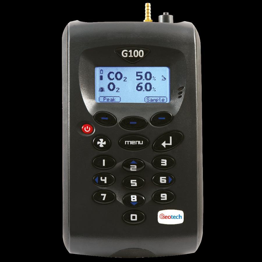
14 Page 14 of 48 GENERAL OPERATIONAL INSTRUCTIONS Note: Fully charge the unit before use when the instrument is first received or if the instrument has been in storage for six months or more. Switching the Instrument On To switch on the instrument, press the On/Off key briefly. There will be a short beep and a slight pause followed by the Geotech logo. The power on self-test will then commence with a short pre-determined self-test sequence. Assuming there are no warnings to display the instrument will continue to the Main Read Screen. Switching the Instrument Off Purge with fresh air. Run the pump for approximately 30 seconds or until the readings have returned to normal levels. Note: Before the instrument is switched off a clean air purge should be performed. This ensures that the instrument is free from gas and ready for the next measurement. This final purge is especially important for the oxygen sensor as it may degrade if stored when contaminated with gas. To switch off the instrument, press the On/Off key briefly. Note: If the Auto Off utilities setting is set to Yes, the analyser will switch off automatically after 10 minutes if not in use. Instrument Main Read Screen After the analyser has been switched on and the warm-up self-tests completed the analyser will display the Main Read Screen. G150 Screen Shown: Battery Power Temperature Probe Connected Soft Keys Alarm Set Peak - Enables the operator to display the peak reading. Store - Enables the operator to store the displayed reading for viewing/download later. Hold - Enables the operator to hold the current reading being taken. Note: The pump is turned off when a reading is stored. Pump (On) Indicator
15 Page 15 of 48 Instrument Status Icons The following icons may be displayed on the instrument read screens: Icon (flashing) (flashing) (flashing) (flashing) (flashing) Description Battery charge state < 1 hour remaining Battery charging Charged Pump running Pump stalled (Backlight turns red) Alarm set Alarm active (Backlight turns red) USB connected to PC (flickers when transferring data) Logging mode active (flashes when memory nearly full) Temperature probe(s) connected Humidity probe connected Service due (every 12 months) Service overdue Fault/repair Waiting Note: A red backlight is displayed if the pump is stalled or the alarm is activated. For further information, please refer to the Alarms or Flow Fail sections. Entering Data During normal operation the user may be prompted to enter data or information via the keypad, i.e. entering an ID code or setting an alarm level. When entering data into the instrument all fields are fixed format and are populated from the right. For example, to enter a new time 09:25:00 the user would type in using the numeric keypad in the following sequence:- * : : 0 * : :09 * : 0:92 * :09:25 * 0:92:50 * 09:25:00 Press the Enter key to confirm/accept data keyed. Any mistakes can be corrected using the soft-key Delete which will delete the last character typed. Alternatively, the sequence can be re-typed before the Enter key is pressed and the existing numbers will be pushed off the screen. Note: The instrument will not allow invalid data to be entered; this should be deleted and reentered.
16 Page 16 of 48 Changing Between Parameters By default, the instrument displays the Main Read Screen (for gas measurement). This shows the CO 2 reading along with the optional O 2 reading. The instrument will return to this screen after power on or when returning from the menus. Key 2 Arrow up can be used to switch to another measurement screen, i.e. temperature or humidity. Continue to press the Scroll key to return to the Main Read Screen. Memory The memory should not be used as a permanent storage medium and any important data should be transferred to a more permanent storage medium as soon as possible. The instrument should not be stored for prolonged periods with valuable data in its memory. Storage When not in use the instrument should be kept in a clean, dry and warm environment, such as an office. It should be stored flat with the stand folded away which helps prolong the life of the O 2 cell. Note: Fully charge the instrument before use if instrument has been stored for six months or more. Main Menu The Main Menu enables the operator to select options to set up specific parameters and perform operational tasks prior to sample readings being taken or to view data/information stored in the instrument. Press the Menu key on the front of the instrument panel and the following screen is displayed: Screen 1 - Main menu Press the soft-key Exit to exit the Main menu. Information The Information option enables the operator to display information such as instrument type, serial number, current software version, service due date and the dates of the last factory and user calibrations. From the Main Read Screen press the Menu key on the instrument panel. Press Key 1 to display general information about the instrument.
17 Page 17 of 48 Screen 2 - Information Utilities The Utilities option enables the operator to configure instrument settings prior to taking readings. From the Main Read Screen press the Menu key on the instrument panel. Press Key 2 to display the Utilities menu and the following screen is displayed: Time & Date Screen 3 - Utilities menu The Time and Date option enables the operator to check or set the instrument s internal clock. The current time/date are appended to every stored reading. From the Main Read Screen press the Menu key on the instrument panel. Press Key 2 to display the Utilities menu. Press Key 1 Time & Date and the Set Time & Date menu is displayed: Screen 4 - Set time & date Press Key 1 to change the time or press Key 2 to change the date. Type the time or date using the numeric keypad followed by the Enter key. The instrument will not allow invalid times or dates to be entered. Note: The clock will need to be manually adjusted to cope with daylight saving changes or
18 Page 18 of 48 changes when crossing time zones. Contrast The Contrast option enables the operator to adjust the instrument screen contrast to compensate for changes in ambient temperature. The default setting is 0. From the Main Read Screen press the Menu key on the instrument panel. Press Key 2 to display the Utilities menu. Press Key 2 to select the instrument panel contrast settings and the following screen is displayed: Screen 5 - Adjust contrast Press Key 3 - Scroll Left and Key 6 - Scroll Right to adjust the value displayed. Press the soft-key Accept or Reject accordingly to accept or reject the changes. Note: The manually set contrast setting is retained when the instrument is switched off. Alarms The G100 range of instruments has the facility to set rising or falling alarms for the two main gas channels, CO 2 and O 2 (if selected as an option). The alarms for each channel can be enabled or disabled independently via the Alarms menu option. Once enabled these alarms become active in the Main Read Screen ; this is indicated by a bell icon. If an alarm is triggered the screen turns red and a flashing bell icon is displayed. The beeper is sounded until the gas level has recovered beyond the trigger point. Rising alarms are triggered when the gas level exceeds the maximum value entered by the user. Falling alarms are triggered when the gas level falls below the minimum value entered by the user. From the Main Read Screen press the Menu key on the instrument panel. Press Key 2 to display the Utilities menu. Press Key 3 to select alarm settings and the following screen is displayed:
19 Page 19 of 48 Screen 6 - Current alarms Press Key 1 to maintain CO 2 alarm and Key 2 to maintain O 2 alarm. Select from the following: 1 Enabled/Disabled: Toggle between disabled and enabled alarm status. 2 Max: Sets the upper limit alarm setting. 3 Min: Sets the minimum alarm setting. The default is 0. Settings Select the option to modify followed by the soft-key Accept or Reject. The Settings option enables the operator to maintain information with regards to taking samples and readings. From the Main Read Screen press the Menu key on the instrument panel. Press Key 2 to display the Utilities menu. Press Key 4 to select settings and the following screen is displayed: Screen 7 - Settings The following instrument settings may be maintained: 1 Prompt ID: Press Key 1 to prompt for ID code for each sample reading, answer Yes or No accordingly. 2 Temperature: Press Key 2 to enter the default unit temperature, choosing from O C or O F. 3 Date: Press Key 3 to switch the date format between dd/mm/yy and mm/dd/yy formats. 4 Auto Off: Press Key 4 to auto switch off the instrument when not in use. Toggle between Yes or No. If set to Yes, the instrument will switch off after 10 minutes if not in use.
20 Page 20 of 48 Flow Fail The Flow Fail option enables the operator to adjust the instrument flow fail detection point should it fail in normal operation with a clean filter. The instrument s internal pump can be stalled when pulling against a vacuum or through a blocked filter. This is indicated by a flashing pump icon and a red screen; to prevent damage to the pump, the pump will switch off after a few seconds. Press the Pump key again to remove the flashing pump icon. Note: Dirty or discoloured filters should be changed before use. Filters that have drawn in water should be changed immediately to prevent damage to the instrument. From the Main Read Screen press the Menu key on the instrument panel. Press Key 2 to display the Utilities menu. Press Key 5 to select flow fail and the following screen is displayed: Screen 8 - Adjust flow fail Use the Scroll keys to adjust the value displayed. The larger the value, the less sensitive the flow fail detection is. Press soft-key Accept or Reject accordingly.
21 Page 21 of 48 Flow Fail Set-up Process Best Practice START Increase the displayed value by 2 Turn pump on Press pump cancel alarm No Decrease the displayed value by 1 Wait 5 seconds No Wait 5 seconds Flow fail alarm? Flow fail alarm? Yes Increase the displayed value by 3 Decrease the displayed value by 1 Turn pump on No Block gas inlet Block gas inlet Wait 5 seconds Flow fail alarm? Wait 5 seconds Flow fail alarm? No Yes Yes Press pump cancel alarm Decrease the displayed value by 1 Blocked or excessive restriction Refer to Section 8.0 Problem Solving Accept END Flow Fail Set-up Process Best Practice G100 Range
22 Page 22 of 48 Logging Data logging mode can be started or stopped via Key 6 - Logging accessed from the Utilities menu. Press Key 4 Start/Stop Logging to start and stop data logging. Whilst in data logging mode the instrument will automatically record data at the pre-set intervals including running the pump for a pre-set time. Active logging mode is indicated on the Main Read Screen by the icon. The operator is able to edit the default ID, pump run-time, interval and start/stop logging. From the Main Read Screen press the Menu key on the instrument panel. Press Key 6 to display the Logging menu and the following screen is displayed: Screen 9 - Logging menu Select the desired option by pressing Keys 1 to 4. Then enter the appropriate setting using the keypad followed by the Enter key. 1 Every 00 mins: Press Key 1 to enter the time in minutes for the timeframe between sample readings. The interval controls the reading frequency in minutes, i.e. every 10 minutes. 2 Pump 00 secs: Press Key 2 to enter the time in seconds for the length of time you wish the pump to run when taking a sample reading. The pump run-time is the time in seconds for which the pump runs prior to the reading being stored. This figure will also need to take into account the length of sample tube and the volume of the sample gas. For example, there is little point setting a pump run-time of 10 seconds if it takes 30 seconds to draw in a new sample. 3 ID : Press Key 3 to create an 8-digit numeric ID Code. 4 Start/Stop Logging: Press Key 4 to start and stop data logging. Note: Data logging mode is automatically stopped when the instrument is switched off or if the logging parameters are edited. Reset The instrument can be reset by pressing Key 7 - Reset accessed via the Utilities menu. Selecting this option will clear all user settings and any stored data including the event log. A confirmation code ( ) must be entered to confirm that a reset is really required.
23 Page 23 of 48 Calibration The G100 range of instruments is fully calibrated during manufacture and when returned for service. However, to improve accuracy between services a user/field calibration can be performed. Note: For further information please refer to Calibration of this manual. View Data The View Data option enables the operator to view the stored readings. From the Main Read Screen press the Menu key on the instrument panel. Press Key 4 to view stored data readings and the following screens are displayed: Screen 10 - View data 1 Screen 11 - View data 2 Press Key 4 - Scroll Left and Key 6 - Scroll Right to move through the stored readings either forwards or backwards. Press Key 2 - Scroll Up and Key 8 - Scroll Down to switch between the first (CO 2, O 2 & Baro) and second (T 1, T 2 & humidity) group of reading parameters. Press the soft-key More to refine or filter the readings to view. Screen 12 - Soft-key 'More' 1 Delete All: Enables the operator to delete all the readings stored 2 Filter: Used to refine/filter the range of readings displayed by ID or date ranges. Press between two dates, after a date, before a date or all dates. 3 Go to: Enables the operator to jump to the first or last reading in the memory or any other reading.
24 Page 24 of 48 Clear Reading Memory The Clear Reading Memory function enables the user to check how many readings have previously been taken and clear them if necessary. Note: Before readings are actually deleted a caution message is displayed; once readings have been deleted they cannot be recovered. The instrument can store up to 1000 readings. The reading structure is fixed and may contain optional parameters not activated for your particular instrument configuration, i.e. oxygen, temperature and humidity. Once the reading memory is full it is not possible to store any more readings. When full and the Store key is pressed or data logging is activated the instrument will show a brief message stating that the memory is full and that no further data will be recorded. From the Main Read Screen press the Menu key on the instrument panel. Press Key 4 to view data. To clear the readings press the soft-key More followed by Key 1 - Delete all. Diagnostics The Diagnostics option enables QED Technical Support to identify and resolve issues with the instrument and readings. If required, the operator may be asked to confirm the diagnostics displayed. From the Main Read Screen press the Menu key on the instrument panel. Press Key 5 to view diagnostics. Note: For further information contact Technical Support at QED on +44(0) or technical@qedenv.co.uk. Warning and Error Codes When switched on the instrument will perform a predetermined self-test sequence taking approximately 30 seconds. During this time many of the instrument s working parameters and settings are checked. If any operational parameters are out of specification or if the pre-programmed recommended calibration/service date has passed, errors or warnings may be displayed. Note: For further information please refer to section Problem Solving of this manual. Battery/Charging Note: Fully charge the unit before use when the instrument is first received or if the instrument has been in storage for six months or more. The battery used in the instrument is 2.6 Ah Lithium-Ion cell. The instrument must be charged using the power supply supplied with your instrument. The power supply supplied is intended for indoor use only. Please ensure adequate ventilation whilst charging. Note: The instrument cannot be powered or charged via the USB connector. Note: When plugged into the power supply the instrument will power on and display charging. When complete the display will change to show that the instrument is charged. To switch the
25 Page 25 of 48 instrument ON whilst charging or charged is displayed, the operator will need to press and hold the power key briefly. Note: Once the instrument is fully charged, the power supply should be disconnected from the instrument. Instrument: Input: 5Vdc ± 0.5V (max 1000mA) Power Supply: Input: Vac 60/50Hz 120mA Output: 5Vdc 1000mA (5VA) Note: A full charge will take approximately 4 hours. Typically, a fully charged battery will last hours. When the instrument is already powered on, the operation is slightly different as the battery icon changes to a flashing plug symbol. This will stop flashing when the charge is complete.
26 Page 26 of 48 TAKING READINGS Preliminary Checks - Best Practice Start Step 1 Instrument has correct time and date set Memory has sufficient space Step 5 Check span calibration Step 7 Step 2 Fit the required filters Step 3 Battery has good charge Step 4 Main gases verified Step 6 Prior to use, it is good practice to ensure that: Step 1 The instrument has the correct time and date set. Step 2 Fit the sample filter checking that it is clean and dry. If experiencing condensation in sample line or the sample filter keeps getting blocked, fit the moisture trap or similar at takeoff point. Step 3 The battery has a good charge (minimum 25% charge, even if only a few readings are required). Step 4 The memory has sufficient space available. Step 5 The main gases have been verified with zero gas concentration present. Step 6 If necessary check the span calibration with a known concentration calibration-check gas. Step 7 Take readings. Do protect the instrument from strong direct sunlight which will quickly raise the temperature of the instrument beyond its operating range and the LCD display will appear almost black. The contrast setting cannot then alter the contrast. Do remember to always use the sample filter! If the sample filter becomes flooded, change it and ensure all sample tubes are clean and dry before re-use. Do not place the instrument against anything hot as this may cause excessive internal temperatures which can lead to erroneous readings. Do not get the instrument wet, for example exposure to rain. Take readings Preliminary Checks (G100 - Best Practice) Always ensure that the exhaust gases emerge in a safe manner into a well ventilated area.
27 Page 27 of 48 Gas Measurement Process Best Practice Start (Switch on) Instrument warm up Main Read Screen Run a Clean Air Purge (no tubes attached) Verify gas Connect Sample Tube from sample point to inlet port Enter ID Code & press Enter ON ID Code prompt field On/Off? Press the Store key (pump will stop) Run until gas readings have stabilised Press the Pump key (draw sample) OFF Default Logging ID used Reading Stored (confirmation message displayed) Instrument automatically returns to the Main Read Screen Take another reading? YES NO Disconnect the Sample Tube from the inlet port Run a Clean Air Purge Gas Measurement Process (G100 - Best Practice) END Depending on preferences the exact reading procedure can change. The following method is considered best practice and when followed correctly will allow quick and consistent readings to be recorded. When the instrument is first switched on it should be purged with fresh air and allowed to stabilise for a few minutes. At this point it is good practice to verify the CO 2 channel. Calibrate only if required. This option is available via the Calibration menu. The instrument is now ready to take the first reading. Connect the sample tube, if relevant (always use the sample filter) from the sample point to the inlet port of the instrument, ensuring the filter is seated correctly. Press the Pump key to draw a sample into the instrument. Notice the main gas readings start to change. It is recommended to run the pump until the gas readings have stabilised (approx. 30 seconds) then press the soft-key Store. The pump will stop and the operator will be prompted to enter an ID code to identify the reading. A reading stored confirmation message will be displayed briefly before returning to the Main Read Screen. Note: The ID code prompt can be switched on or off. This option is accessed via the Settings menu, then press Key 1 - Prompt for ID: Yes or No. If the ID prompt is set to No the reading is
28 Page 28 of 48 stored using the default logging ID. After each reading the instrument should be purged with fresh air. Disconnect the sample tube from the instrument. Then, run the pump for a minimum of 30 seconds. The gas readings should return to nominal values for fresh air. Regardless of the instrument configuration the following data will be stored for each reading:- ID code (8 characters) Reading Type (0=User, 1=Auto, 2=peak, 3=hold) Current time/date Gas readings (CO 2, O 2 ) Sample pressure (for indication only) Temperature x 2 Humidity Alternative Reading Methods There are three other reading types or methods which each require slightly different operating procedures. Logged reading Peak reading Hold reading Logged Reading Logged readings need to be configured and initiated via the Utilities menu by pressing Key 6 - Logging. During configuration the user will be asked to supply an ID, reading interval and pump runtime. These parameters are used to control the reading frequency in logging mode. Once logging mode is activated the instrument will automatically record a reading at every interval until stopped by the operator or the memory becomes full. Logging is also suspended temporarily whilst the user is accessing the menu options. Whilst the logging mode is active the Hold, Pump and Store key will be deactivated, only logged readings can be stored. Peak Reading The operator can toggle the reading mode between normal (current) and peak readings. Whilst in peak reading mode the instrument will only display peak values for each of the channels. These values can then be stored by pressing the Store key or automatically at the appropriate logging interval (if logging is enabled). The peak value is reset after a reading is stored or by exiting the peak mode using the appropriate soft-key. The current mode of operation can be identified by the status of the soft-key, either Normal or Inverse, where inverse indicates peak mode is active.
29 Page 29 of 48 Hold Reading The Hold Reading option allows the user to freeze the currently displayed reading. This allows it to be manually recorded or moved away from the sample point. Once activated, press the soft-key Hold and the readings are fixed until the Hold key is pressed again or by storing the reading. The current mode of operation can be identified by the status of the soft-key which is inversed whilst in the hold phase. Screen 13 - Hold reading
30 Page 30 of 48 CALIBRATION User Calibration The G100 range of instruments is fully calibrated during manufacture and when returned for service. However, to improve accuracy between services a user/field calibration can be performed. This section sets out the correct procedures to achieve an accurate user calibration. Note: If the calibration is completed incorrectly it may decrease the accuracy of the instrument. Two important terms that are used within this section are Zero and Span. Zero: The point at which the instrument is calibrated when there is none of the target gas present. Span: The point at which the instrument is calibrated when a known quantity of the target gas is present. Calibration Gases User calibration of the instrument will improve the data accuracy in the range of the calibration gases used. However, it may cause less accurate readings of concentrations outside this calibrated range. Users should select the correct calibration gas for the expected gas levels on their particular application. Only use gases with a known certified gas concentration. Note: Certified calibration gases can be supplied by QED. For each gas used the appropriate material safety data sheet must be read and understood before proceeding. Calibration gases and the use of pressure regulators can be dangerous. Calibration Set-up The regulator supplied with the calibration kit has been configured to deliver a fixed flow. It only requires a few turns to open and no adjustment is necessary. Exhaust Port When the instrument is being calibrated, there are two possible exits for the gas; via the usual manner out of the exhaust port of the instrument or in cases of over-pressurisation the 1/16 port on the pressure relief valve. It is recommended that both ports have exhaust tubing attached. The exhaust tubing must emerge in a well-vented area. Ensure there are no leaks in the tubing and connections. The calibration should always be carried out in a safe area with all necessary precautions taken as all pressurised gases are potentially dangerous.
31 Page 31 of 48 Calibration Equipment The diagram below displays the regulator and tubing equipment for user calibration: Certified calibration gas in 58 litre gas canisters is supplied with the QED calibration kit. Please refer to the QED website for further information. The regulator supplied with the calibration kit is recommended as flow and pressure rates are factory set. Note: Maximum input pressure 250mb, maximum flow 300ml.
32 Page 32 of 48 Calibration Method Before you begin ensure the unit is turned on and allowed to stabilise at its working temperature before performing any of the calibration options, this will typically be minutes. To achieve the processes set out in this section, press Key 3 Calibration from the Main menu. The first screen displayed provides the option to select the gas that requires calibration. Screen 14 - Calibration menu The exact calibration method can vary depending on the gases used. Reset Factory Settings This option will reset the instrument to its factory programmed calibration characteristics and will clear the user calibration points for both gas channels. To reset to factory settings, press Key 1 - Factory Reset from the Calibration menu. Screen 15 - Reset calibration screen To prevent the user calibration data being accidentally erased the user must confirm the action by pressing the soft-key Accept, or soft-key Reject to exit without change. Zero CO 2 Channel For maximum accuracy it is recommended that the CO 2 Channel is zeroed using bottled gas (certified 100% N 2). However, if nitrogen gas is not available the optional soda lime filter kit can be fitted to the gas inlet. This allows the user to perform a zero using normal air as the soda lime filter will absorb virtually all CO 2 from the sample air. For both these options select 'Key 1-Zero with N 2' from the user calibration menu. If neither of the recommended methods is available the user can select the option to perform an air calibration. This option assumes that the user has access to fresh air at around 390ppm. Generally, this can be found outside or in a well ventilated corridor (typically, an office or lab would have a higher CO 2 concentration). From the Calibration Menu, press Key 2 - CO 2 channel.
33 Page 33 of 48 Screen 16 - CO2 channel menu Press either Key 1 - Zero with N 2 (recommended) or Key 2 - Zero with Air from the menu. Then, either attach the 100% N 2 or sample pipe to allow access to fresh air. Ensure the zero gas has flowed and is stable. Press the Start key. The instrument will now wait (approximately 60 seconds) for the gas reading to stabilise at the correct level. If zeroing with air press the Pump key to draw in fresh air. The instrument will then indicate a successful zero has been completed. Press the soft-key Accept to confirm the calibration and Store the new user offset. Alternatively, soft-key Reject to exit without change. Note: If the calibration failed then purge and try again or select a different air source. Note: If using G110 very high concentrations of CO 2 may take up to 30 minutes to purge completely. Span CO 2 Channel It is recommended that the instrument is spanned to target the desired reading range (e.g. 5%); ideally this should not be a low level close to zero. If not already preset, enter the span target, i.e. certified concentration of your calibration gas. Press Key 1 and enter the new value. Then attach the gas and open regulator valve to allow the gas to flow. Press the Start key and wait for the reading to stabilise. This can take a couple of minutes. Once a stable reading is shown press the soft-key Accept. A successful span calibration message will then be displayed. Press the soft-key Accept again to confirm the calibration and Store the new user span. Alternatively, press soft-key Reject to exit without change. Note: If the calibration failed then try again using a longer purge time or different target gas. Zero O 2 Channel It is not required to zero the O 2 channel. A span calibration corrects the reading across the whole range. Span O 2 Channel It is recommended that the O 2 channel is spanned in fresh air with a target concentration of 20.9%, although other gases and target concentrations can be used if required.
34 Page 34 of 48 If not already preset, enter the span target, i.e. certified concentration of your calibration gas. Press the soft-key Start and wait for the reading to stabilise. Press the Pump key to draw in fresh air. It can take a couple of minutes to stabilise. Once a stable reading is shown press the soft-key Accept. A successful span calibration message should then be displayed. Press the soft-key Accept again to confirm the calibration and Store the new user span. Alternatively, press soft-key Reject to exit without change. Note: If the calibration failed then try again using a longer purge time or different target gas. Last Field Calibration This data can be found in the Information screen accessed via the Utilities menu. This option displays the date that the last field calibration was perfomed on the instrument. Calibration Record The G100 instruments have the facility to log user calibrations via the Event Log. This can be used as an aid in ensuring that gas measurements are valid and accurate. During calibration the instrument will record the following in the event log. For each entry the time and date will be stored. Event Successful user zero CO 2 Successful user span CO 2 Successful user span O 2 Failed user zero CO 2 Failed user span CO 2 Failed user span O 2 Return to factory settings Data Recorded Type (N 2 or Air) and Readings before and after Target Value, Readings before and after Target Value, Readings before and after Type (N 2 or Air) and Reading Target Value, Gas Reading Target Value, Gas Reading Note: If the calibration failed, then try again using a longer purge time or different target gas. This event log can only be downloaded and viewed via the optional Analyser Data Manager software. It cannot be viewed on the analyser screen.
35 Page 35 of 48 PROBLEM SOLVING This section outlines various warning and error messages which the operator may receive during general operation of the instrument. For further assistance please contact Technical Support at QED on +44(0) or Warnings and Errors When switched on the instrument will perform a predetermined self-test sequence. During this time many of the instrument s working parameters and settings are checked. If any operational parameters are out of specification or if the pre-programmed recommended calibration/service date has passed, errors or warnings may be displayed. Use the Scroll Up and Scroll Down keys to move through the list if required. There are two types of warning that may be displayed: General warnings that may not affect the instrument s function and those where the self-test has detected a function that is outside the usual operating criteria, e.g. battery charge low, memory nearly full. Operational parameters that could affect the performance of the instrument, e.g. CO 2 out of calibration. The most likely reason for these errors is either an incorrect user calibration, or may indicate sensor failure. If an incorrect user calibration has caused the warning it should be correctable by way of returning the instrument to factory settings, zeroing or carrying out a user calibration as necessary for the relevant function. Under and Over Range Codes If a reading is over range (i.e. above the maximum allowed reading) it will be displayed with more than chevrons (>>.>). This can occur if a channel has been incorrectly calibrated or the sample gas has exceeded its specified range (e.g. CO 2 > 20%). If a reading is under range (i.e. below zero) it will be displayed with less than chevrons (<<. <). Refer to section Calibration of this manual to remedy under-range by performing a user zero. A number displayed as asterisks (**.*) indicates an error, usually where the instrument has been unable to complete a particular calculation. Typically, this will be the first indication of a fault condition. Where no data is available dashes (--.-) are displayed. This usually occurs when a particular reading or parameter has been skipped by the user, or where an optional accessory is not fitted correctly, i.e. a temperature probe. Flow Fail Warning Occasionally an instrument may report a flow fail that is caused by a blocked or flooded inlet filter, please refer to section Flow Fail for further information.
36 Page 36 of 48 Self-test Warning Messages The following warnings may be displayed during the self-test period when the instrument is switched ON. Warning Icon Description Check Memory The instrument only has space to store less than 50 readings before it is full. The exact number can be checked using the View Readings option. Memory Full There is no more space in memory to store readings. Both the store and log options will be disabled until the memory is cleared. The readings should be downloaded to PC using the optional download software before memory is cleared. Battery Low The instrument does not have enough power to operate for a full day. The instrument should be recharged or connected to an external power supply. Service Due It has been 12 months (or more) since your instrument was returned to the manufacturer for a service. The performance and accuracy of the instrument may be impaired. User Cal. Due It has been over a month since the instrument was last user calibrated. For optimal performance and accuracy it is recommended that the instrument is user calibrated each time it is used. Invalid Time The instrument has an invalid time. This is most likely to occur after a reset. The correct time should be entered using the set Time & Date option via the Utilities menu. Invalid Date The instrument has an invalid date. This is most likely to occur after a reset. The correct date should be entered using the set Time & Date option via the Utilities menu. Baro. Fault The instrument has detected a fault with the barometric sensor or its calibration. This will have an effect on the accuracy of the readings as they are pressure compensated. The instrument will need to be returned to the manufacturer for service. Sensor 0-8 range This indicates that one of the measurement channels within the analyser has an issue on start-up. Please contact technical support for further guidance. Note: Certain configuration problems can be corrected remotely. Using the Analyser Data Manager software, it is possible to export the current configuration and it to the manufacturer s Technical Support or Service Department. Depending on the type of error it may be possible to correct the configuration file and import it back into the instrument.
37 Page 37 of 48 User Calibration Trouble Shooting Error User Zero failed Calibration failed Remedy A possible reason for this is because the instrument is trying to zero to a level which is outside the predetermined range set when the unit was calibrated at the factory or; the gas is not stable i.e. is still flushing the measure gas or is using ambient air/gas that is varying in concentration. To rectify this, first ensure the unit contains absolutely none of the gas which is being zeroed by flushing thoroughly with nitrogen. If it will not zero, then refer to the instructions given in the Factory Settings section. If the instrument continues to fail to zero then the unit must be returned to the manufacturer for investigation. Check the span target is set to the correct value, if not, correct and retry spanning the channel. Repeat the entire procedure, including zeroing the channel and then calibrate the span. Ensure the reading is stable before spanning the channel. User Calibration Explained Graph 1 - User calibration explained User calibration is a means of optimising the performance of the instrument to the current operating conditions such as ambient temperature and pressure as well as correcting for instrument drift caused by lamp and filter settling. In general, the instrument should not require calibration more than once a month, but we do recommend verifying the instruments operation each day.
38 Page 38 of 48 User calibration has two operations and each may be performed individually, however for a complete user calibration both must be completed. Factory Calibration When the instrument is factory calibrated, a stable gas curve is generated (see curve 1 on Graph 1 - User calibration explained). This curve is then used to determine the gas concentration based on the infrared signal strength after being absorbed by the gas. Zero Calibration A zero calibration is used to correct the entire curve for the infrared source and filter variations caused by aging and induced drift due to dirt and other contaminants. If done correctly, there is often no need to complete a span calibration, as the new curve will follow closely to the factory calibration curve (curve 1 on Graph 1 - User calibration explained). The zero calibration is very sensitive and a rushed or poor calibration, (such as the target gas still being present), will result in a zero error; see point A on curve 2 of Graph 1 - User calibration explained. This also produces an error throughout the remainder of the curve proportional to signal strength, but the effect on the span is significant, see point B on Graph 1 - User calibration explained. Note: To perform an accurate user calibration it is critical that a good user zero has been performed. QED recommend that this be done in nitrogen in order to guarantee that none of the gas of interest is present. Note: The Zero calibration is very sensitive and even 100% instruments will detect in the 0 to 100ppm range even though they do not display to this resolution. Please refer to Graph 2 - Typical zero gas purge times. Span Calibration A span calibration is used to optimise the analyser at the span calibration concentration (see point C on Graph 1 - User calibration explained) for the current operational conditions. It corrects the span point but leaves the zero unadjusted (this will be left at the last user zero if this has been performed) and should be done at the concentration of interest in the particular application. If the user zero is poor and the span calibration is good, it will correct the gas curve for the point of interest, but other points on the curve could be incorrect, see curve 3 on Graph 1 - User calibration explained. Typical Calibration Purge Times Typical zero calibration although displaying zero needs to be given time to settle. We recommend commencing the calibration at least five minutes after the display concentration stabilises. Note: If using G110 very high concentrations of CO 2 may take up to 30 minutes to purge completely.
39 Page 39 of 48 Typical Zero Gas Purge Time Gas % display reads 0.0% w ait to Start Zero calibration :00 01:00 02:00 03:00 04:00 05:00 06:00 07:00 08:00 09:00 10:00 11:00 Time (mm:ss) Graph 2 - Typical zero gas purge times Cross-Gas Effects Carbon dioxide is measured by infrared absorption at a wavelength specific to carbon dioxide. Therefore, the carbon dioxide reading will not be affected by any other gases. The oxygen sensor is a galvanic cell type and suffers virtually no influence from CO 2, CO, H 2S, NO 2, SO 2 or H 2, unlike many other types of oxygen cell. Error Due to CO 2 Solubility in Water Due to the water trap and filter it is possible that some of the CO 2 in the sample gas will be absorbed in to any trapped water. Hardware Reset If for any reason the instrument locks up and will not switch off, or the instrument appears off and will not turn on, it is possible to force an emergency power off. Pressing and holding the On/Off key for 10 seconds will power off the instrument. Once this time has elapsed, the instrument can be powered on as normal. Note: Performing a hardware reset may cause loss or corruption of currently stored data including the time/date.
40 Page 40 of 48 SERVICE The G100 instrument should be regularly serviced to ensure correct operation and accurate readings. The manufacturer recommends a full service and recalibration every 12 months. Depending on usage the O 2 cell should be replaced every 2-3 years. User Serviceable Parts Note: There are no user serviceable parts inside the instrument. Please do not attempt any repair as this may invalidate any warranty supplied with your instrument. The following parts are supplied by your instrument manufacturer and can be replaced by the user: Sample Filter Sample Tubing Cleaning This should be regularly inspected for damage or discolouration and changed if needed. The instrument should never be operated without the sample filter as this may result in water or dust entering the instrument. The filter should be changed immediately if water can be seen. Failure to do so can damage the instrument. Always ensure that sample tubes are not contaminated or damaged. The instrument and accessories (including power supply unit) can be wiped clean using a non-fibrous damp cloth. Note: Do NOT apply pressure to the LCD display as this can cause damage. Do NOT apply any moisture to the moisture removal tube on the rear of the instrument as this may damage the membranes. Do NOT use solvents or any other chemical cleaners.
41 Page 41 of 48 WARRANTY POLICY
42 Page 42 of 48
43 Page 43 of 48 EVENT LOG The following events are recorded in the instrument s event log. The event log can only be downloaded using the additional Analyser Data Manager software. Please refer to the Analyser Data Manager software manual for further details. Event Cold Start/Reset Firmware Version Set time Set date Re-flash requested Restore to factory settings Comms clear memory Change contrast Change flow fail current limit Battery less than critical voltage RTC date/time invalid Factory calibration invalid or overdue Service invalid or overdue Power on self-test, sensor out of range User calibration set zero OK User calibration set span OK User calibration set zero failed User calibration set span failed Attempt to store when readings memory full Readings memory nearly full Change logging mode Change logging mode ID Flow fail current limit exceeded Data Type of start (MCUSR, boot_key) Description Before and After Before and After None Type Type 0=Readings, 1=Event Log Before and After Before and After Critical, Actual None Date, difference Date, difference Channel, reading, limit Before, After Target, Before, After Target, Reading Target, Reading Max Limit, Actual Status, Interval, Pump time ID Limit, Actual

44 Page 44 of 48 WEEE COMPLIANCE WEEE COMPLIANT The wheelie bin symbol now displayed on equipment supplied by QED signifies that the apparatus must not be disposed of through the normal municipal waste stream but through a registered recycling scheme. The Waste Electrical and Electronic Equipment directive (WEEE) makes producers responsible from July 1 st 2007 in meeting their obligations, with the fundamental aim of reducing the environmental impact of electrical and electronic equipment at the end of its life. QED is now registered with the Environmental Agency as a producer and has joined a recycling scheme provider who will manage and report on our electrical waste on our behalf. Our Producer Registration Number is WEE/GB0052TQ So when your instrument is at the end of its life, please contact the Sales team at QED who will advise you on the next step in order to help us meet our obligations.
G100 Range. Operating Manual
 Operating Manual G100 CO 2 0-20% G110 CO 2 0-100% G150 CO 2 0-10,000ppm VIASENSOR 2355 Bishop Circle West Dexter, MI. 48130 Toll Free: 855 VIASENSOR Tel: +1 (800) 968-2026 Fax: +1 (909) 825-0591 Email:
G200 RANGE G200 AND G210 OPERATING MANUAL
 G200 RANGE G200 AND G210 OPERATING MANUAL Page 2 of 61 Table of Contents Manual Guidelines... 5 Safety Related Information... 5 Hyperlinks... 5 Notes... 5 Introduction... 6 The G200 Analyser... 6 The G210
G200 Analyzer Range. Operating Manual
 G200 Analyzer Range Operating Manual G200 N 2 0 0-1,000ppm G210 N 2 0 0-100% VIASENSOR 850 South Via Lata Suite 112 Colton, CA 92324 USA Toll Free: 855 VIASENSOR Tel: +1 (909) 783-9472 Fax: +1 (909) 825-0591
G200 Analyser Range. Operating Manual
 G200 Analyser Range Operating Manual G200 N20 0-1,000ppm G210 N20 0-100% Geotechnical Instruments (UK) Ltd Sovereign House Queensway Leamington Spa Warwickshire CV31 3JR England Tel: +44 (0)1926 338111
Columbus Instruments
 0215-003M Portable O 2 /CO 2 /CH 4 Meter User s Manual Columbus Instruments 950 NORTH HAGUE AVENUE TEL:(614) 276-0861 COLUMBUS, OHIO 43204, USA FAX:(614) 276-0529 1 www.colinst.com TOLL FREE 1-800-669-5011
OXY Integral. INTERCON ENTERPRISES INC Tel: Fax: Internet:
 OXY Integral INTERCON ENTERPRISES INC Tel: 800 665 6655 Fax: 604 946 5340 E-Mail: sales@intercononline.com Internet: www.intercononline.com Manual Integral 2006 1 INDEX 2-3 PREFACE 4 INTRODUCTION 5 Principle
Pressure Automated Calibration Equipment
 GE Measurement & control Pressure Automated Calibration Equipment Safety Instructions and User Guide - K0447 PACE5000 PACE6000 K0447 Issue No. 9 1 10 1 PACE5000 1 2 3 4 5 PACE6000 2 6 7 8 3 4 5 6 7 8 9
Datasheet: K-30 ASCII Sensor
 Datasheet: K-30 ASCII Sensor The K30 ASCII sensor is a low cost, infrared and maintenance free transmitter module intended to be built into different host devices that require CO2 monitoring data. The
Using the UltraRAE. Firmware 2.35
 Using the UltraRAE Firmware 2.35 Training Agenda UltraRAE features Setting up the UltraRAE Turning on the UltraRAE Idle Operation RAE-Sep Tubes Prepping for a measurement Taking a measurement Alarm modes
Instruction Manual Dräger MSI P7 and MSI P7 plus
 Dräger MSI GmbH Rohrstraße 32 58093 Hagen Tel.: +49-2331 / 9584-0 Fax: +49-2331 / 9584-29 e-mail: info@draeger-msi.de D 923; Edition 2011-01-01 Content 1. General Hints Page 4 2. The Instrument 2.1 Front
Do Not Print This Page.
 Do Not Print This Page. Load 1 sheet of cardstock paper. Print Page 2 - the cover For the body of the text, load 3 sheets of 28lb matte finish paper into the printer. Print pages 3, 5, 7 (Sheet 1, 2, 3)
GEM 2000 GAS ANALYZER & EXTRACTION MONITOR OPERATION MANUAL
 GEM 2000 GAS ANALYZER & EXTRACTION MONITOR OPERATION MANUAL Copyright 2003 by CES-LANDTEC All rights reserved. Printed in the United States of America. No part of this book may be used or reproduced in
GEM 2000 GAS ANALYZER & EXTRACTION MONITOR OPERATION MANUAL
 GEM 2000 GAS ANALYZER & EXTRACTION MONITOR OPERATION MANUAL Copyright 2001 by CES-LANDTEC All rights reserved. Printed in the United States of America. No part of this book may be used or reproduced in
RAM Operation Manual
 RAM 4021-1 Operation Manual Worldwide Manufacturer of Gas Detection Solutions TABLE OF CONTENTS RAM 4021-1 For Your Safety... 2 Description... 2 Setup Mode... 3 Lights/Alarms... 3 Operation... 4 Calibration...
Pegas 4000 MF Gas Mixer InstructionManual Columbus Instruments
 Pegas 4000 MF Gas Mixer InstructionManual Contents I Table of Contents Foreword Part I Introduction 1 2 1 System overview... 2 2 Specifications... 3 Part II Installation 4 1 Rear panel connections...
RAM Operation Manual. Worldwide Manufacturer of Gas Detection Solutions
 RAM 4021 Operation Manual Worldwide Manufacturer of Gas Detection Solutions TABLE OF CONTENTS RAM 4021 For Your Safety... 2 Description.... 2 Setup Mode.... 2 Lights/Alarms.... 3 Operation.... 4 Calibration....
Atlas 6TM. Indoor Air Quality Monitor Instruction Manual. Measures CO 2, Temperature and Humidity DISTRIBUTED BY
 Atlas 6TM Indoor Air Quality Monitor Instruction Manual Measures C 2, Temperature and Humidity DISTRIBUTED BY INTRDUCTIN Thank you for purchasing this meter. This device measures ppm levels, temperature
GEM-500 OPERATION MANUAL
 GEM-500 OPERATION MANUAL Copyright 2001 by CES-LANDTEC All rights reserved. Printed in the United States of America. No part of this book may be used or reproduced in any form or by any means, or stored
RAM Operation Manual. Worldwide Manufacturer of Gas Detection Solutions
 RAM 4021 Operation Manual Worldwide Manufacturer of Gas Detection Solutions TABLE OF CONTENTS RAM 4021 For Your Safety... 2 Description.... 2 Setup Mode.... 2 Lights/Alarms.... 3 Operation.... 4 Calibration....
Pneumatic high-pressure controller Model CPC7000
 Calibration technology Pneumatic high-pressure controller Model CPC7000 WIKA data sheet CT 27.63 Applications Automotive and avionics industry Industry (laboratory, workshop and production) Transmitter
Pneumatic high-pressure controller Model CPC7000
 Calibration technology Pneumatic high-pressure controller Model CPC7000 WIKA data sheet CT 27.63 Applications Healthcare and avionics industry Industry (laboratory, workshop and production) Transmitter
CONSOLE-320 ENGLISH. 230A: CONSOLE-320 with cable data output Item 230B: CONSOLE-320 with cable + wireless radio data output
 CONSOLE-320 Item 230A: CONSOLE-320 with cable data output Item 230B: CONSOLE-320 with cable + wireless radio data output Table of contents 1. INTRODUCTION...2 1.1 Power supply...2 1.2 Connections...2 1.3
User manual CF8-D/W-IN
 User manual CF8-D/W-IN General The sensor CF8-D/W-IN is used to measure the carbon dioxide concentration inside incubators. All functions can be modified from a PC with the communication cable. UMA 48
RAM 4021-PR. Operation Manual. Worldwide Manufacturer of Gas Detection Solutions
 RAM 4021-PR Operation Manual Worldwide Manufacturer of Gas Detection Solutions TABLE OF CONTENTS RAM 4021-PR For Your Safety... 2 Description.... 2 Setup Mode.... 2 Lights/Alarms.... 3 Operation.... 4
Appendix D: SOP of INNOVA 1412 Photoacoustic Multi-Gas Monitor. Description and Principle of Operation
 Page 1 of 19 : SOP of INNOVA 1412 Photoacoustic Multi-Gas Monitor Description and Principle of Operation The photoacoustic multi-gas monitor (INNOVA 1412, Innova AirTech Instruments, Denmark) is a highly
TEL/jlRE" Introduction. Display Features and Modes. Startup Procedure. Power-Up Procedure. Adjustment Modes
 TEL/jlRE" Introduction The Telaire 7001 CO 2 /T emperature monitor (shown in Fi gt u e 1 below) is an easy to use hand-held instnunent, which provides stable and highly accurate readings due to Telaire
Instructions for Assembly, Installation, and Operation of the Gas Addition Kit Accessory with the CEM Discover Systems
 Corporation Issued: 5/09 P/N: 600104 Rev. 2 Instructions for Assembly, Installation, and Operation of the Gas Addition Kit Accessory with the CEM Discover Systems The Gas Addition Accessory permits the
The Univentor 1250 Anaesthesia Unit
 THE UNIVENTOR 1200/1250 ANAESTHESIA UNIT The Univentor 1250 Anaesthesia Unit TABLE OF CONTENTS EDITION 1 Section 1 - WARRANTY & SERVICE 1.1. WARRANTY 2 1.2. DAMAGED SHIPMENTS 2 1.3. SERVICE 2 Section 2
GA5000 Gas Analyzer. Operating Manual
 Operating Manual QED Environmental Systems, Inc. 2355 Bishop Circle West Dexter, MI. 48130 Tel: (800) 624-2026 Fax: (734) 995-1170 Email: info@qedenv.com Website: www.landtecna.com Page 1 of 69 GA5000
Hydro-Control V User Guide
 Hydro-Control V User Guide Hydronix Part no: HD0193 Version 2.3.0 Revision date: July 2006 1 COPYRIGHT Neither the whole or any part of the information contained in nor the product described in this documentation
HPICAL Operation & Data Logging Procedures. Click spacebar to advance through slides 1
 HPICAL-15000 Operation & Data Logging Procedures Click spacebar to advance through slides 1 WARNING Always wear proper safety equipment when using high pressure equipment. Do not exceed 125 psi air pressure.
BUBBLER CONTROL SYSTEM
 BUBBLER CONTROL SYSTEM Description: The HDBCS is a fully automatic bubbler system, which does liquid level measurements in water and wastewater applications. It is a dual air compressor system with, air
Bante821 Portable Dissolved Oxygen Meter Instruction Manual
 Bante821 Portable Dissolved Oxygen Meter Instruction Manual BANTE INSTRUMENTS CO., LTD Bante821 Portable Dissolved Oxygen Meter 1 Introduction Thank you for selecting the Bante821 portable dissolved oxygen
RAM 4021-DPX Operation Manual
 RAM 4021-DPX Operation Manual Worldwide Manufacturer of Gas Detection Solutions TABLE OF CONTENTS ABL 4021-DPX / RAM 4021-DPX For Your Safety... 3 Description... 3 Setup Mode... 4 Lights/Alarms... 4 Operation...
Best Practice Guide, Servomex 2700
 For full installations details refer to the. Best Practice Guide, Servomex 2700 Mounting: General Guidelines: Servomex 2700 Control Units and air supplies (utilities units) should, ideally, be mounted
OxyScan Graphic. Operating Instructions. UMS Micro-oxygen sensor 501. Microprocessor instrument
 OxyScan Graphic Operating Instructions UMS Micro-oxygen sensor 501 Microprocessor instrument Introduction Thank you for choosing the UMS Micro Oxygen Sensor 501 - a highly advanced product! Please read
KERN EG/EW Version /02
 E KERN EG/EW Version 1.5 07/02 Operating Instructions Electronic Precision Balances Contents 1 TECHNICAL DATA... 20 2 UNPACKING AND STANDARD ACCESSORIES... 23 3 SETTING UP THE BALANCE... 23 4 EXTERNAL
Digital Vacuum Regulator
 Temperature Control for Research and Industry Digital Vacuum Regulator User s Manual Model 300 INDEX SECTION PAGE 1. QUICK OPERATING INSTRUCTIONS........................... 3 Safety Notices.................................................
User Manual. asense VAV. CO 2 / temperature sensor with built-in general purpose controller
 Gas and Air Sensors User Manual asense VAV CO / temperature sensor with built-in general purpose controller General The IAQ-sensor product asense VAV is used to measure indoor air carbon dioxide concentration
Bante820 Portable Dissolved Oxygen Meter Instruction Manual
 Bante820 Portable Dissolved Oxygen Meter Instruction Manual BANTE INSTRUMENTS CO., LTD Bante820 Portable Dissolved Oxygen Meter 1 Introduction Thank you for selecting the Bante820 portable dissolved oxygen
REASONS FOR THE DEVELOPMENT
 7 Series 7 Series +24VDC VDC OUTPUT MICROPROCESS. E P IN EXH OUT 7 Series 7 ø,8 8 7 Series 9 5 8 9 7 Series Display features The proportional regulator has a 3 /2 digit display and a three-pushbutton
Nothing's as cool, as a freshwater pool. easychem 770 ORP and ph Controller for Pools and Spas with Timer Output for Pool Pump
 Page 1 of 6 TPS Australia - Quality hand-made instruments since 1968. Nothing's as cool, as a freshwater pool easychem 770 ORP and ph Controller for Pools and Spas with Timer Output for Pool Pump Automatic
Operator Quick Guide ORBISPHERE 3654
 Operator Quick Guide ORBISPHERE 3654 Revision H - 14/03/2008 Operating Information About this Guide The information in this guide has been carefully checked and is believed to be accurate. However, Hach
JOLLY2. Installation user s manual. 6 different operating modes selectable. version 3.3. DATA TO BE FILLED OUT BY THE INSTALLER (Page 1)
") ENGLISH ENGLISH ENGLISH ENGLISH Installation user s manual Warning! electrical scheme modified JANUARY 2005 version 3.3 JOLLY2 DATA TO BE FILLED OUT BY THE INSTALLER (Page 1) 6 different operating modes
ENGLISH ENGLISH ENGLISH ENGLISH Installation user s manual Warning! electrical scheme modified JANUARY 2005 version 3.3 JOLLY2 DATA TO BE FILLED OUT BY THE INSTALLER (Page 1) 6 different operating modes
CF8-W-Disp-CO. User manual. CO 2 / CO sensor with built-in general purpose controller
 User manual CF8-W-Disp-CO CO 2 / CO sensor with built-in general purpose controller General The IAQ-sensor product CF8-W-Disp-CO is used to measure indoor air carbon dioxide and carbon monoxide concentrations.
BIOGAS 5000 Gas Analyzer. Operating Manual
 Operating Manual QED Environmental Systems, Inc. 2355 Bishop Circle West Dexter, MI. 48130 Phone: (800) 624-2026 Fax: (734) 995-1170 Email: info@qedenv.com Website: www.qedenv.com Page 1 of 61 Table of
Instruction Manual. Model DSP-Ex Portable Dewpoint Meter. Alpha Moisture Systems Alpha House 96 City Road Bradford BD8 8ES England
 Model DSP-Ex Portable Dewpoint Meter Instruction Manual Alpha Moisture Systems Alpha House 96 City Road Bradford BD8 8ES England Tel: +44 1274 733100 Fax: +44 1274 733200 Email: info@amsytems.co.uk Web:
GEM5000 Gas Analyzer. Operating Manual
 Operating Manual QED Environmental Systems, Inc. 2355 Bishop Circle West Dexter, MI. 48130 Tel: (800) 624-2026 Fax :(734) 995-1170 Email: info@qedenv.com Website: www.landtecna.com Page 1 of 70 OMGEM5KN4.7.1
RAM 4021 Operation Manual
 RAM 4021 Operation Manual Worldwide Manufacturer of Gas Detection Solutions TABLE OF CONTENTS RAM 4021 For your safety...3 Description...3 Set-up mode...4 Annunciator lights/alarms...4 Operation...5 Calibration...6
ACV-10 Automatic Control Valve
 ACV-10 Automatic Control Valve Installation, Operation & Maintenance General: The Archer Instruments ACV-10 is a precision automatic feed rate control valve for use in vacuum systems feeding Chlorine,
Technical Information Conducal CLY421
 TI00496C/07/EN/01.12 71142150 Products Solutions Services Technical Information Conducal CLY421 Conductivity calibration set for ultrapure water applications Factory calibrated measurement box Certified
Scoreboard Operator s Instructions MPC Control
 Scoreboard Operator s Instructions MPC Control Some features on the keyboard overlay may not be included on the particular model being operated. Since 1934 Retain this manual in your permanent files 1/21/2011
Portable Gas Monitor GX User Maintenance Manual (H4-0050)
") H4E-0050 Portable Gas Monitor GX-8000 User Maintenance Manual (H4-0050) Need of Maintenance and Servicing This gas monitor must be maintained in a normal state at all times to prevent accidents due to
H4E-0050 Portable Gas Monitor GX-8000 User Maintenance Manual (H4-0050) Need of Maintenance and Servicing This gas monitor must be maintained in a normal state at all times to prevent accidents due to
UNITY 2 TM. Air Server Series 2 Operators Manual. Version 1.0. February 2008
 UNITY 2 TM Air Server Series 2 Operators Manual Version 1.0 February 2008 1. Introduction to the Air Server Accessory for UNITY 2...2 1.1. Summary of Operation...2 2. Developing a UNITY 2-Air Server method
BI-680 Online Dissolved Oxygen Controller Instruction Manual
 BI-680 Online Dissolved Oxygen Controller Instruction Manual BANTE INSTRUMENTS CO., LTD BI-680 Online Dissolved Oxygen Controller 1 Introduction Thank you for selecting the BI-680 online dissolved oxygen
Remote Control Bait Boat
 CARPIO 2.0 User Manual All pictures shown are for illustration purpose only. Actual product may vary due to product enhancement Remote Control Bait Boat (Smart Remote Control at 868 MHz) 1 Table of Contents
SATURN EVO COLOR A N A E S T H E S I A S Y S T E M. Manufacturer of high quality anaesthesia products
 Saturn Evo SATURN EVO COLOR A N A E S T H E S I A S Y S T E M i n t e l l i g e n t s i m p l i c i t y Manufacturer of high quality anaesthesia products SATURN EVO COLOR PATIENT SAFETY AND USER PATIENT
CDS-2000 CO 2 Sensor Verification, Calibration, and Troubleshooting Bulletin
 Electronic Control Manual 216 Sensors and Stats Section S Technical Bulletin CDS-2000 Issue Date 0393 CDS-2000 CO 2 Sensor Verification, Calibration, and Troubleshooting Bulletin Introduction 3 Pre-Verification
Getting to know your Sureshotgps micro V3
 Getting to know your Sureshotgps micro V3 Battery State Symbol Satellite Signal Shows distance to front, centre and rear of each green Hole Number Real Time Power on and Enter Key Down (backward) Key 1
Specifications and information are subject to change without notice. Up-to-date address information is available on our website.
 www.smar.com Specifications and information are subject to change without notice. Up-to-date address information is available on our website. web: www.smar.com/contactus.asp LD302 - AssetView HMI LD302
PROPORTIONING VALVE. Model 150 INSTRUCTION MANUAL. March 2017 IMS Company Stafford Road
 PROPORTIONING VALVE Model 150 INSTRUCTION MANUAL March 2017 IMS Company 10373 Stafford Road Telephone: (440) 543-1615 Fax: (440) 543-1069 Email: sales@imscompany.com 1 Introduction IMS Company reserves
PTG100 Precision Test Gauge
 PTG100 Precision Test Gauge User Manual PD1007 Rev B 03/28/2014 Palmer Instruments Inc. 234 Old Weaverville Road Asheville, NC 28804 Toll Free: 800-421-2853 Phone: 828-658-3131 Fax: 828-658-0728 Email:
8.1 Calibration of gas sensors
 8.1 Calibration of gas sensors! CAUTION! Calibration gas handling and precautions Observe safety regulation and accident prevention regulations when using or handling test gases. Use test gases in well-ventilated
Description. Measuring Device 3760XBI USP. Balancing
 Measuring Device 3760XBI Description 3760XBI comprises from a differential pressure unit with an integrated true differential pressure sensor for the exact measuring of both differential and static pressures
Race Screen: Figure 2: Race Screen. Figure 3: Race Screen with Top Bulb Lock
 Eliminator Competition Stand Alone Mode - Instruction Manual Main Menu: After startup, the Eliminator Competition will enter the Main Menu. Press the right/left arrow buttons to move through the menu.
DF-550E PROCESS ANALYSERS APPLICATIONS FEATURES
 PROCESS ANALYSERS DF-550E The DF-550E Nano Trace oxygen analyser is a Coulometric sensor based analyser designed to measure oxygen as a contaminant at ultra trace levels in ultra high purity electronic
Manual Weighingblock VB2 series and Uniscale
 Manual Weighingblock VB2 series and Uniscale Note: At page 8 in this manual you will find a short form instruction. Normally the only instruction shipped together with the Scale. Overview different ranges.
Heavy Duty Dissolved Oxygen Meter
 User's Manual Heavy Duty Dissolved Oxygen Meter Model 407510 Test Equipment Depot - 800.517.8431-99 Washington Street Melrose, MA 02176 FAX 781.665.0780 - TestEquipmentDepot.com Introduction Congratulations
TABLE OF CONTENTS INTRODUCTION 3 SAFETY PRECAUTIONS 3 PACKAGE CONTENTS 4 DEVICE OVERVIEW 4 BUTTON OPERATION SUMMARY 5 BASIC OPERATION 6
 TABLE OF CONTENTS INTRODUCTION 3 SAFETY PRECAUTIONS 3 PACKAGE CONTENTS 4 DEVICE OVERVIEW 4 BUTTON OPERATION SUMMARY 5 BASIC OPERATION 6 CURRENT TIME MODE 7 FUNCTIONAL DISPLAY 7 WEATHER FORECAST FEATURE
Overview. Front Panel: Keypad and Display
 Overview The GA-200B is an analyzer that integrates a gas sampling system with sensors to measure and display the concentrations of oxygen and carbon dioxide in a sample as the percentage of a gas in the
O2100C Oxygen Measurement Module Technical Use Notes do not use other wall adapters with the O2100Cmodule. 10% / V 5% / V 2% / V 1% / V 10% / V
 O2100C Oxygen Measurement Module The O2100C module measures the partial pressure of O2 and thus the module output is proportional to the pressure in the sample cell. Gas sampled must be free of liquids
This test shall be carried out on all vehicles equipped with open type traction batteries.
 5.4. Determination of hydrogen emissions page 1 RESS-6-15 5.4.1. This test shall be carried out on all vehicles equipped with open type traction batteries. 5.4.2. The test shall be conducted following
BGA244 Binary Gas Analyzer
 Quick Start Guide Revision 1.0 Certification Warranty Service certifies that this product met its published specification at the time of shipment. This product is warranted against defects in materials
Model GFC 7000T CO 2 Analyzer (Addendum to GFC 7000TA Manual, PN 07272)
") Manual Addendum Model GFC 7000T CO 2 Analyzer (Addendum to GFC 7000TA Manual, PN 07272) P/N M07273 DATE 06/11/13 TELEDYNE ELECTRONIC TECHNOLOGIES Analytical Instruments 16830 Chestnut Street City of Industry,
Manual Addendum Model GFC 7000T CO 2 Analyzer (Addendum to GFC 7000TA Manual, PN 07272) P/N M07273 DATE 06/11/13 TELEDYNE ELECTRONIC TECHNOLOGIES Analytical Instruments 16830 Chestnut Street City of Industry,
New product release. Universal Rebreather Monitor (URBM) Three cell / Independent backup
 Three cell / Independent backup") New product release Closed Circuit Research is pleased to announce the launch of our range of Universal Rebreather Monitors Universal Rebreather Monitor (URBM) Three cell / Independent backup Key features
New product release Closed Circuit Research is pleased to announce the launch of our range of Universal Rebreather Monitors Universal Rebreather Monitor (URBM) Three cell / Independent backup Key features
STANDARD OPERATING PROCEDURES. Andersen Instruments Federal Reference Method (FRM) Ambient Particulate (PM 10 /PM 2.
 Ambient Particulate (PM 10 /PM 2.") STANDARD OPERATING PROCEDURES Andersen Instruments Federal Reference Method (FRM) Ambient Particulate (PM 10 /PM 2.5 ) Sampler (RAAS) AMBIENT AIR MONITORING PROGRAM for the 130 LIBERTY STREET DECONSTRUCTION
STANDARD OPERATING PROCEDURES Andersen Instruments Federal Reference Method (FRM) Ambient Particulate (PM 10 /PM 2.5 ) Sampler (RAAS) AMBIENT AIR MONITORING PROGRAM for the 130 LIBERTY STREET DECONSTRUCTION
Technical Data Sheet MF010-O-LC
 Technical Data Sheet MF010-O-LC - 1 - 1. Properties The oxygen measuring system MF010-O-LC determines the oxygen content in gas mixtures up to a temperature of 250 C. It is particularly suitable for the
Hand-held pressure calibrator with integrated pump Model CPH6600
 Calibration technology Hand-held pressure calibrator with integrated pump Model CPH6600 WIKA data sheet CT 16.01 Applications Calibration service companies and service industry Measurement and control
Arena by Oregon Scientific
 Arena by Oregon Scientific 1 Model: SW288 User Manual Arena by Oregon Scientific SWIMWATCH (SW288) USER MANUAL CONTENTS Introduction... 3 Control buttons... 3 LCD... 4 Getting started... 5 Activate watch
SDM-2012 Docking Station Standalone Configuration Operator s Manual
 SDM-2012 Docking Station Standalone Configuration Operator s Manual Part Number: 71-0254RK Revision: P5 Released: 10/5/12 www.rkiinstruments.com Warranty RKI Instruments, Inc. warrants gas alarm equipment
DPC-30 DPC-100. Reference Manual
 DPC-30 DPC-100 Reference Manual 1. Introduction 1.1 Description The Martel DPC Digital Pneumatic Calibrator improves upon traditional dial gauge pneumatic calibrators. The Martel DPC improves accuracy,
High Performance Electronic Components 1411 S. Roselle Rd Schaumburg, IL Fax
 Air Quality Computer U.S. PATENT #5,509,295 Invented and Manufactured By High Performance Electronic Components 1411 S. Roselle Rd Schaumburg, IL 60193 847-923-0002 Fax 847-923-0004 www.altronicsinc.com
The HumiSys. RH Generator. Operation. Applications. Designed, built, and supported by InstruQuest Inc.
 The HumiSys RH Generator Designed, built, and supported by InstruQuest Inc. Versatile Relative Humidity Generation and Multi-Sensor System The new HumiSys with single or dual RH probes capabilities is
SomnoSuite FAQ. Setup. Calibration 4. What are the calibration requirements for the SomnoSuite? Settings
 SomnoSuite FAQ V1.3 January 2015 Setup 1. How do I connect the SomnoSuite to my oxygen source? 2. Is there a way to speed up the downward movement of the pusher block when setting the empty position? 3.
SCOPE OF THIS GUIDE STARTING-UP. 1 Check mini CORI-FLOW functional properties
 Quick Installation Guide Doc nr.: 9.17.052H Date: 10-12-2015 SCOPE OF THIS GUIDE mini CORI-FLOW instruments are highly accurate instruments for measuring and controlling the mass flow rate of liquids and/or
FireHawk M7 Interface Module Software Instructions OPERATION AND INSTRUCTIONS
 FireHawk M7 Interface Module Software Instructions OPERATION AND INSTRUCTIONS WARNING THE WARRANTIES MADE BY MSA WITH RESPECT TO THE PRODUCT ARE VOIDED IF THE PRODUCT IS NOT USED AND MAINTAINED IN ACCORDANCE
Precision digital pressure gauge Model CPG1000
 Calibration technology Precision digital pressure gauge Model CPG1000 WIKA data sheet CT 10.01 Applications Oil and gas industry Maintenance and service facilities Calibration service companies and service
Quick Installation Guide Doc nr.: C Date:
 Quick Installation Guide Doc nr.: 9.17.093C Date: 13-05-2016 SCOPE OF THIS GUIDE mini CORI-FLOW instruments are highly accurate instruments for measuring and controlling the mass flow rate of liquids and/or
nvisti Kestrel Companion Pro For Android
 nvisti Kestrel Companion Pro For Android The nvisti Kestrel Companion App is the most versatile, accurate and user friendly dual purpose app available. This app allows for both remote viewing for firing
Inert Air (N2) Systems Manual
 Systems Manual") INSTRUCTION MANUAL Inert Air (N2) Systems Manual N2-MANUAL 2.10 READ AND UNDERSTAND THIS MANUAL PRIOR TO OPERATING OR SERVICING THIS PRODUCT. GENERAL INFORMATION Positive pressure nitrogen gas pressurizing
INSTRUCTION MANUAL Inert Air (N2) Systems Manual N2-MANUAL 2.10 READ AND UNDERSTAND THIS MANUAL PRIOR TO OPERATING OR SERVICING THIS PRODUCT. GENERAL INFORMATION Positive pressure nitrogen gas pressurizing
Additel 761 Automated Pressure Calibrators Selection Guide
 / Process Calibration Equipment Automated Calibrators Selection Guide Model Features Range Module 1 761-LLP 761-D 761-L 761-LA 761-M 761-MA 761-H 761-HA 761-BP -2.5 to 2.5 mbar (-1 to 1 inh 2 O) -0.95
Additel 761 Automated Pressure Calibrators
 Automated Calibrators UPDATED Fully automated pressure calibrator with built-in pressure generator / controller to as high as 600 psi (40 bar) or as low as 0.01 Pa (0.00004 inh 2 O) accuracy Dual pressure
TR Electronic Pressure Regulator. User s Manual
 TR Electronic Pressure Regulator Page 2 of 13 Table of Contents Warnings, Cautions & Notices... 3 Factory Default Setting... 4 Quick Start Procedure... 5 Configuration Tab... 8 Setup Tab... 9 Internal
AMT-Ex Dewpoint Transmitter
 AMT-Ex Dewpoint Transmitter Instruction Manual Alpha Moisture Systems Alpha House 96 City Road Bradford BD8 8ES England Tel: +44 1274 733100 Fax: +44 1274 733200 email: mail@amsytems.co.uk web: www.amsystems.co.uk
BUBBLER CONTROL SYSTEM
 BUBBLER CONTROL SYSTEM Description: The LDBCS is a fully automatic bubbler system, which does liquid level measurements in water and wastewater applications. It is a dual air compressor system with, air
ISM-3 User Manual PBI D 04/2013
 ISM-3 User Manual PBI-200114-D 04/2013 ISM-3 EN User Manual ISM-3 User Manual Published by: Dansensor A/S Rønnedevej 18, DK-4100 Ringsted Denmark Tel.: +45 57 66 00 88 Fax: +45 57 66 00 99 E-mail: info@dansensor.com
5000TOC Sensor Standard Operating Procedure for TOC Calibration Conductivity Calibration Temperature Calibration Flow Rate Calibration
 Part No. 84468 5000TOC Sensor Standard Operating Procedure for TOC Calibration Conductivity Calibration Temperature Calibration Flow Rate Calibration This document contains proprietary information, which
with O 2 Controller Instruction Manual
 14500 Coy Drive, Grass Lake, Michigan 49240 734-475-2200 E-mail: sales@coylab.com www.coylab.com Hypoxic Cabinets (In-Vivo / In-Vitro) with O 2 Controller Instruction Manual Index Page Warranty 2 Warnings
OMGA5KN Iss Copyright Geotechnical Instruments (UK) Ltd
 Ltd") Page 2 of 126 TABLE OF CONTENTS Manual guidelines... 6 Hazard warnings and safety symbols... 6 Notes... 6 Introduction... 7 Safety instructions... 7 MCERTS... 10 CIRIA... 11 EU Declaration of conformity...
Page 2 of 126 TABLE OF CONTENTS Manual guidelines... 6 Hazard warnings and safety symbols... 6 Notes... 6 Introduction... 7 Safety instructions... 7 MCERTS... 10 CIRIA... 11 EU Declaration of conformity...
OPERATOR S MANUAL Ar-Gone Weld Gas Analyzer
 July 2011 OPERATOR S MANUAL Ar-Gone Weld Gas Analyzer WARNING! Before operating this product, read and understand this Operator s Manual. Become familiar with the potential hazards of this unit. Contact