G R I P P E R S English edition 10/2012
|
|
|
- Elmer French
- 6 years ago
- Views:
Transcription


1 GRIPPERS English edition 10/2012


2 76 GRIPPERS CONTENTS PRECISION PARALLEL GRIPPERS PRECISION PARALLEL MINI GRIPPERS UNIVERSAL PARALLEL GRIPPERS LONG-STROKE GRIPPERS
3 77 UNIVERSAL ANGULAR GRIPPERS SPECIAL ACCESSORIES for Parallel Mini Grippers 109 Ø3 Ø L
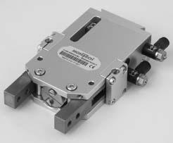
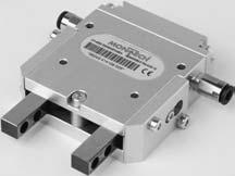
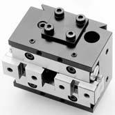
4 78 PRECISION PARALLEL GRIPPERS GPP PRODUCT DESCRIPTION The Precision Parallel Gripper GPP is used for demanding applications. The GPP is designed for internal and external gripping and is double-acting. It can easily be converted between the functions «open when depressurized» and «closed when depressurized». The end positions can be detected by means of proximity switches. The gripper body contains tapped holes for fitting external positioners or part sensing devices. Safety throttling orifices protect the grippers against overloading by high forces of the gripping fingers. The high precision the ball bearings guarantee a high mechanical efficiency, a remarkably long life and high reliabilty.


5 79 APPLICATIONS Revolver pivot unit; with Rotary Drive DAP and two Grippers GPP for workpiece loading and unloading. Precise gripping and rotary movement; without radial deviation of the workpiece relative to the axis of rotation, realized by means of a Rotary Drive DAPI with internal air supply.


6 80 PRECISION PARALLEL GRIPPERS GPP/GPPI/GPP-ISO Three sizes in three variants each. With dovetail for easy mounting/adjustment and with standard pattern of holes for all sizes. I version; for mounting on a Rotary Drive DAPI with internal air supply. ISO version; gripper mounting according to ISO A40 for robots. SCOPE OF DELIVERY With clamping device for proximity switches and a spring. GPP-ISO with two exhaust throttles. Internal air versions without compressed air supplies. SUITABLE ACCESSORIES Accessories from page 303 Quick-Set from page 1
7 81 GRIPPING FORCE DIAGRAM EXAMPLES Example GPP-1 External gripping without spring Operating pressure 5 bar L = 70 mm F1 = 28 N Example GPP-2 Internal gripping without spring Operating pressure 5 bar L = 100 mm F2 = 82 N F1, F2 = Gripping force per gripper finger B in gripped state [mm] External gripping with spring (closed when depressurized) Operating pressure 5 bar L = 60 mm B = 53 mm F1 = 35 N F1 at 0 bar = 6 N Internal gripping with spring (open when depressurized) Operating pressure 5 bar L = 80 mm B = 80 mm F2 = 117 N F2 at 0 bar = 32 N DEFINITION AND LOAD CALCULATIONS AT THE GPP-GRIPPER F1, 2 Gripping force [N], as gripping force diagram Fy, Fz Outer, forces acting [N] Lx, Ly, Lz Distances of force application [m] Mx, My, Mz Load moments [Nm] b Load factor: must not exceed the value 1! K1, K2, K3 Load limit constants European projection K1 K2 K3 GPP GPP GPP Mx = Fz Ly + Fy Lz My = F1, 2 Lz + Fz Lx Mz = F1, 2 Ly + Fy Lx b = Mx + My + Mz < 1 K1 K2 K3
8 82 PRECISION PARALLEL GRIPPERS GPP/GPPI SIZE 1 Gripping distance = stroke [mm] 6 Gripping distance adjustable opening/closing yes Efficiency 0.77 Opening/Closing time 1) [s] Weight GPP/GPPI [kg] 0.25/0.26 Mass moment of inertia Jz [kgcm 2 ] 0.87 Operating pressure [bar] 3 6 Operating medium air, oiled or unoiled, filtered to 5 µm, dew point < 6 C Repeatability 2) [mm] ± Check on end position open/closed 3) inductive proximity switches Pneumatic connection M5 Thread for mounting positioners 4xM3 Ambient: Temperature [ C] Rel. humidity < 95% (without condensation) Air purity normal workshop atmosphere Warranty 2 years from the date of delivery Maintenance none needed Mounting position any Material aluminum, steel, bronze, plastic 1) Measured at max. travel between 3 and 6 bar, without spring 2) Scatter of the gripper end position after 100 successive strokes under constant conditions 3) See accessories page 303 GRIPPING FORCE DIAGRAM Gripping force per gripper finger F1, F2 [N] p = 6 bar p = 5 bar p = 4 bar p = 3 bar p = 6 bar + Fed p = 5 bar + Fed p = 4 bar + Fed p = 3 bar + Fed Fed max. finger length L [mm] B in gripped state (mm) p = pneumat. pressure Fed = Spring Gripping direction F2 F1
9 83 European projection GPP ø40 GPPI Clamping sleeve for proximity switch 6.5 dia GPP 40 GPPI 28 GPP 32 GPPI 3 Y 4 X 12.5 min max ) F* 1 F* 2 F* 2 F* 1 L* M3x5 (4x) ) 2) B min. 50/max. 56 Stroke 6 26 ±0.02 1) Hole M4x8 View Y GPPI Air supply per mounting part ± ±0.1 Thread 10 ±0.02 3H7x5 View Y GPP 9.5 View X Gripping jaw H8 M3x ±0.05 M3x6 M3x6 Air supply M * See gripping force diagram 1) Dimension of jaws closed (min.) and open (max.) 2) Position of proximity switch when jaws fully closed 3) Position of proximity switch when jaws fully open Ref. No. GPP GPPI
10 84 PRECISION PARALLEL GRIPPERS GPP-ISO SIZE 1 Gripping distance = stroke [mm] 6 Gripping distance adjustable opening/closing yes Efficiency 0.77 Opening/Closing time 1) [s] Weight [kg] 0.28 Mass moment of inertia Jz [kgcm 2 ] 0.87 Operating pressure [bar] 3 6 Operating medium air, oiled or unoiled, filtered to 5 µm, dew point < 6 C Repeatability 2) [mm] ± Check on end position open/closed 3) inductive proximity switches Pneumatic connection adjustable exhaust throttles M5, with plug, hose-ø 4 mm Thread for mounting positioners 4xM3 Ambient: Temperature [ C] Rel. humidity < 95% (without condensation) Air purity normal workshop atmosphere Warranty 2 years from the date of delivery Maintenance none needed Mounting position any Material aluminum, steel, bronze, plastic 1) Measured at max. travel between 3 and 6 bar, without spring 2) Scatter of the gripper end position after 100 successive strokes under constant conditions 3) See accessories page 303 GRIPPING FORCE DIAGRAM Gripping force per gripper finger F1, F2 [N] p = 6 bar p = 5 bar p = 4 bar p = 3 bar p = 6 bar + Fed p = 5 bar + Fed p = 4 bar + Fed p = 3 bar + Fed Fed max. finger length L [mm] B in gripped state (mm) p = pneumat. pressure Fed = Spring Gripping direction F2 F1
11 85 European projection ± ø25 g6 Clamping sleeve for proximity switch 6.5 dia X 12.5 min max ) 3 L* Air supply Exhaust throttles with plug 4 dia. M3x5 (4x) ) 2) F* 1 F* 2 F* 2 F* 1 B min. 50/max. 561) Stroke 6 20 ±0.01 M5x9 View X Gripping jaw ø6 h ±0.05 M3x H8 7.5 M3x5 M3x * See gripping force diagram 1) Dimension of jaws closed (min.) and open (max.) 2) Position of proximity switch when jaws fully closed 3) Position of proximity switch when jaws fully open Ref. No. GPP-1-ISO 39814
12 86 PRECISION PARALLEL GRIPPERS GPP/GPPI SIZE 2 Gripping distance = stroke [mm] 12 Gripping distance adjustable opening/closing yes Efficiency 0.82 Opening/Closing time 1) [s] Weight GPP/GPPI [kg] 0.68/0.68 Mass moment of inertia Jz [kgcm 2 ] 4.3 Operating pressure [bar] 3 6 Operating medium air, oiled or unoiled, filtered to 5 µm, dew point < 6 C Repeatability 2) [mm] ± 0.02 Check on end position open/closed 3) inductive proximity switches Pneumatic connection M5 Thread for mounting positioners 4xM3 Ambient: Temperature [ C] Rel. humidity < 95% (without condensation) Air purity normal workshop atmosphere Warranty 2 years from the date of delivery Maintenance none needed Mounting position any Material aluminum, steel, bronze, plastic 1) Measured at max. travel between 3 and 6 bar, without spring 2) Scatter of the gripper end position after 100 successive strokes under constant conditions 3) See accessories page 303 GRIPPING FORCE DIAGRAM Gripping force per gripper finger F1, F2 [N] p = 6 bar p = 5 bar p = 4 bar p = 3 bar p = 6 bar + Fed p = 5 bar + Fed p = 4 bar + Fed p = 3 bar + Fed Fed B in gripped state (mm) max. finger length L [mm] Gripping direction F2 F1 p = pneumat. pressure Fed = Spring
13 87 European projection GPP ø40 GPPI Housing contour of GPPI Clamping sleeve for proximity switch 6.5 dia Y GPP 57 GPPI 42 GPP 49 GPPI X 12.5 max. 50 min. 38 1) L* 1.2 M3x6 (4x) ) 2) F* 1 F* 2 F* 2 B min. 75/max. 871) Stroke ±0.02 Hole F* 1 M4x8 View Y GPPI Air supply per mounting part ±0.1 3H7x5 10 ±0.02 View Y GPP 12 View X Gripping jaw 18 ±0.05 M4x6 21 5H8 26 ±0.1 Thread M4x5 M4x Air supply M * See gripping force diagram 1) Dimension of jaws closed (min.) and open (max.) 2) Position of proximity switch when jaws fully closed 3) Position of proximity switch when jaws fully open Ref. No. GPP GPPI
14 88 PRECISION PARALLEL GRIPPERS GPP-ISO SIZE 2 Gripping distance = stroke [mm] 12 Gripping distance adjustable opening/closing yes Efficiency 0.82 Opening/Closing time 1) [s] Weight GPP-ISO [kg] 0.72 Mass moment of inertia Jz [kgcm 2 ] 4.3 Operating pressure [bar] 3 6 Operating medium air, oiled or unoiled, filtered to 5 µm, dew point < 6 C Repeatability 2) [mm] ± 0.02 Check on end position open/closed 3) inductive proximity switches Pneumatic connection adjustable exhaust throttles M5, with plug, hose-ø 4 mm Thread for mounting positioners 4xM3 Ambient: Temperature [ C] Rel. humidity < 95% (without condensation) Air purity normal workshop atmosphere Warranty 2 years from the date of delivery Maintenance none needed Mounting position any Material aluminum, steel, bronze, plastic 1) Measured at max. travel between 3 and 6 bar, without spring 2) Scatter of the gripper end position after 100 successive strokes under constant conditions 3) See accessories page 303 GRIPPING FORCE DIAGRAM Gripping force per gripper finger F1, F2 [N] p = 6 bar p = 5 bar p = 4 bar p = 3 bar p = 6 bar + Fed p = 5 bar + Fed p = 4 bar + Fed p = 3 bar + Fed Fed B in gripped state (mm) max. finger length L [mm] Gripping direction F2 F1 p = pneumat. pressure Fed = Spring
15 89 European projection 75 ø25 g Clamping sleeve for proximity switch 6.5 dia Air supply Exhaust throttles with plug 4 dia. 4 X 12.5 max. 50 min. 38 1) L* 1.2 M3x6 (4x) ) ) 4.5 F* 1 F* 2 F* 2 F* 1 B min. 75/max. 87 Stroke 12 1) 20 ± M5x12 ø6 h6 View X Gripping jaw 18 ±0.05 M4x6 21 5H8 M4x5 M4x * See gripping force diagram 1) Dimension of jaws closed (min.) and open (max.) 2) Position of proximity switch when jaws fully closed 3) Position of proximity switch when jaws fully open Ref. No. GPP-2-ISO 39817
16 90 PRECISION PARALLEL GRIPPERS GPP/GPPI SIZE 3 Gripping distance = stroke [mm] 20 Gripping distance adjustable opening/closing yes Efficiency 0.86 Opening/Closing time 1) [s] 0.12 Weight GPP/GPPI [kg] 1.32/1.42 Mass moment of inertia Jz [kgcm 2 ] 14.0 Operating pressure [bar] 3 6 Operating medium air, oiled or unoiled, filtered to 5 µm, dew point < 6 C Repeatability 2) [mm] ± 0.03 Check on end position open/closed 3) inductive proximity switches Pneumatic connection M5 Thread for mounting positioners 4xM4 Ambient: Temperature [ C] Rel. humidity < 95% (without condensation) Air purity normal workshop atmosphere Warranty 2 years from the date of delivery Maintenance none needed Mounting position any Material aluminum, steel, bronze, plastic 1) Measured at max. travel between 3 and 6 bar, without spring 2) Scatter of the gripper end position after 100 successive strokes under constant conditions 3) See accessories page 303 GRIPPING FORCE DIAGRAM Gripping force per gripper finger F1, F2 [N] p = 6 bar + Fed p = 5 bar + Fed p = 4 bar + Fed p = 3 bar + Fed Fed B in gripped state (mm) p = 6 bar p = 5 bar p = 4 bar p = 3 bar max. finger length L [mm] Gripping direction F1 F2 p = pneumat. pressure Fed = Spring
17 91 European projection GPP ø40 GPPI Clamping sleeve for proximity switch 6.5 dia GPP 68 GPPI 55 GPP 60 GPPI Y X 16 min ) max L* M4x9 (4x) 22 3) ) 5 F* 1 F* 2 F* 2 F* 1 B min. 100/max ) Stroke 20 View Y GPPI Air supply per mounting part 26 ±0.02 Hole M4x ± ±0.1 Thread 3H7x5 10 ±0.02 View Y GPP 21.5 View X Gripping jaw 23.5 ±0.05 M4x H8 M4x7 M4x Air supply M * See gripping force diagram 1) Dimension of jaws closed (min.) and open (max.) 2) Position of proximity switch when jaws fully closed 3) Position of proximity switch when jaws fully open Ref. No. GPP GPPI
18 92 PRECISION PARALLEL GRIPPERS GPP-ISO SIZE 3 Gripping distance = stroke [mm] 20 Gripping distance adjustable opening/closing yes Efficiency 0.86 Opening/Closing time 1) [s] 0.12 Weight GPP-ISO [kg] 1.42 Mass moment of inertia Jz [kgcm 2 ] 14.0 Operating pressure [bar] 3 6 Operating medium air, oiled or unoiled, filtered to 5 µm, dew point < 6 C Repeatability 2) [mm] ± 0.03 Check on end position open/closed 3) inductive proximity switches Pneumatic connection M5 Thread for mounting positioners 4xM4 Ambient: Temperature [ C] Rel. humidity < 95% (without condensation) Air purity normal workshop atmosphere Warranty 2 years from the date of delivery Maintenance none needed Mounting position any Material aluminum, steel, bronze, plastic 1) Measured at max. travel between 3 and 6 bar, without spring 2) Scatter of the gripper end position after 100 successive strokes under constant conditions 3) See accessories page 303 GRIPPING FORCE DIAGRAM Gripping force per gripper finger F1, F2 [N] p = 6 bar + Fed p = 5 bar + Fed p = 4 bar + Fed p = 3 bar + Fed Fed B in gripped state (mm) p = 6 bar p = 5 bar p = 4 bar p = 3 bar max. finger length L [mm] Gripping direction F1 F2 p = pneumat. pressure Fed = Spring
19 93 European projection ø25 g Clamping sleeve for proximity switch 6.5 dia Air supply M X 16 min ) max L* M4x9 (4x) 22 3) ) 5 F* 1 F* 2 F* 2 F* 1 B min. 100/max. 1201) Stroke ±0.01 View X Gripping jaw M5x12 ø6h6 M4x ±0.05 5H M4x7 M4x Air supply M * See gripping force diagram 1) Dimension of jaws closed (min.) and open (max.) 2) Position of proximity switch when jaws fully closed 3) Position of proximity switch when jaws fully open Ref. No. GPP-3-ISO 45094

 which ensures advanced operational")
 or across the guide direction (size 2).")

20 96 PRECISION PARALLEL MINI GRIPPERS GPPM PRODUCT DESCRIPTION The Precision Mini Gripper GPPM was developed for handling small parts in confined installation conditions. The GPPM is dualacting; it can be used for internal or external spans. At the heart of the Precision Mini Gripper is a precise ball guide (patented) which ensures advanced operational safety, longevity, high precision and a high degree of mechanical efficiency. Compressed air can be supplied from above (size 1) or across the guide direction (size 2). As an option, the end positions at size 2 can be queried with proximity switches which are attached to the housing by means of an attachment set. SCOPE OF DELIVERY GPPMI-1: without clamping device for proximity switches. GPPM-2Y: with clamping device for proximity switches and two plug-type connections. SUITABLE ACCESSORIES Special accessories page 109 Accessories from page 303 Quick-Set from page 1
21 97 DEFINITION AND CALCULATION My Mx Lx Lx Fy Fy M 0x = (F 0z L y + F 0y (L z + 4)) M 0y = (F s (L z + 4) + F 0z L x ) Ly Mz Fz (F S ) (F S ) Fz Lz M 0z = (F s L y + F 0y L x ) Combined loading B 0 = M 0x + M 0y + M 0z <_ 1 K 1 K 2 K 3 K 1 K 2 K 3 F 0y max [N] F 0z max [N] GPPM-1 GPPMI GPPM-2Y F s : F 0y, F 0z : F 0y max, F 0z max : L x, L y, L z : M 0x, M 0y, M 0z : K 1, K 2, K 3 : B 0 : Gripping force [N] (as gripping force diagram) Forces acting [N] Max. permissible static forces per jaw [N] Distances of force application [mm] Static load moments [Nm] Load limit constants Load factor: must not exceed the value 1!
22 98 PRECISION PARALLEL MINI GRIPPERS GPPMI-1 GPPM-2Y Gripping distance = stroke [mm] 4 6 Piston diameter [mm] Gripping force [N] see gripping force diagrams Opening/Closing time 1) [s] Weight [kg] Mass moment of inertia Jz [kgcm 2 ] Operating pressure [bar] Operating medium air, oiled or unoiled, filtered to 5 µm, dew point < 6 C Repeatability 2) [mm] ± 0.02 ± Check on end position open/closed inductive proximity switches Pneumatic connection Ø 1 mm M3 with plug-type connection for hose Ø 3 mm Thread for mounting positioners 4 x M2 4 x M2.5 Noise level [dba] < 62 Ambient: Temperature [ C] Rel. humidity < 95% (without condensation) Air purity normal workshop atmosphere Warranty 2 years from the date of delivery Maintenance none needed Mounting position any Material aluminum, steel, bronze 1) Measured at max. stroke and a pressure of 5 bar 2) Scatter of the gripper end position after 100 successive strokes under constant conditions GRIPPING FORCE DIAGRAM GPPM GPPMI-1 GPPM-2Y F S (N) p = 6 bar p = 5 bar p = 4 bar p = 3 bar LZ F S (N) p = 6 bar p = 5 bar p = 4 bar 14 p = 3 bar L Z (mm) L Z (mm) Gripping force per gripper finger = f (LZ, p)
23 103 European projection GPPMI-1 Ø2H7x3 deep Hole Hole View A Gripping jaw Air supply M2.5x3 deep Ø2H8x2.5 deep M2.5x3.5 deep M2x2.5 deep Ref. No. GPPMI
24 108 European projection GPPM-2Y 9 9 Clamping device for proximity switches Ø A Ø2H7x4 deep 15 ± ± ± Hole 7 Hole 11 ±0.05 M3x3 deep View A Gripping jaw Distance plate Activation plate Air supply with plug 3 dia. 6.2 ± ± ± Ø2.5H8x3 deep M3x4 deep ±0.05 ±0.1 Ref. No. GPPM-2Y 50415

25 109 SPECIAL ACCESSORIES FOR GPPM ADAPTERS for installation with Quick-Set size 20 for GPPM-2Y ACCESSORIES INDUCTIVE PROXIMITY SWITCH Ø 3 mm PNP, short-circuit and reverse polarity protected, sensing distance 0.6 mm, flush-mountable, with LED L = 2000 mm Ø3 Ø L PNEUMATICS CONNECTIONS 1 Threaded outgoing air-throttle M3, with angled swivel connection, pluggable, Ø 3 mm Angled screw connector M3, pluggable, Ø 3 mm Screw-connector M3, straight, pluggable, Ø 3 mm

26 112 UNIVERSAL PARALLEL GRIPPERS GPU/GPUI PRODUCT DESCRIPTION The Universal Parallel Gripper GPU/GPUI possess an extremely robust, low-friction guide system for the jaws, in which the main forces are transferred by cylindrical rollers. The efficiency is very high. The grippers are extremely compact and the pneumatic connections plus the proximity switches are arranged on the narrow side. As a result, several grippers can be mounted side by side in a very small space. The high repeatability, combined with the high gripping force per gripper weight, can also convince demanding users. A safety orifice protects the gripper against overloading by unduly high mass force of the gripping fingers. SCOPE OF DELIVERY With clamping device for proximity switches and a plug-type connection. I versions without exhaust throttles. SUITABLE ACCESSORIES Accessories from page 303 Quick-Set from page 1
27 113 DEFINITION OF LOAD Mox Moy Fs Lz Foy Fs Fs Lx Lx Foz Foy Fs Ly Foz Moz GPU/GPUI-10 GPU/GPUI-14 GPU/GPUI-20 GPU/GPUI-25 perm. [N] see gripping force diagram Foy perm. [N] Foz perm. [N] Lx perm. [mm] Ly perm. [mm] Lz perm. [mm] (Lx + Ly) perm. [mm] (Ly + Lz) perm. [mm] (Lz + Lx) perm. [mm] Mox perm. = (Foy. Lz) + (Foz. Ly) [Nmm] Moy perm. = (. Lz) + (Foz. Lx) [Nmm] Moz perm. = (. Ly) + (Foy. Lx) [Nmm] : Gripping force per gripper finger [N] Foy, Foz: Static forces [N] Lx, Ly, Lz: Distances of force application [mm] Mox, Moy, Moz: Static load moments [Nmm] When Mox, Moy, Moz act simultaneously, each may attain its permitted maximum.
28 114 UNIVERSAL PARALLEL GRIPPERS GPU-10/GPUI-10 Gripping distance = stroke [mm] 5 Piston diameter [mm] 10 Opening time at 5 bar 1) [s] Closing time at 5 bar 1) [s] 0.02 Weight GPU/GPUI [kg] 0.15 Mass moment of inertia Jz [kgcm 2 ] 0.23 Max. cycles per minute max. 80 double stroke per minute Operating pressure [bar] 4 6 Operating medium air, oiled or unoiled, filtered to 5 µm, dew point < 6 C Repeatability at 5 bar 2) [mm] ± 0.02 Check on end position open/closed 3) inductive proximity switches Pneumatic connection pluggable hose-ø 4 mm Ambient: Temperature [ C] Rel. humidity < 95% (without condensation) Air purity normal workshop atmosphere Warranty 2 years from the date of delivery Maintenance after 10 mio. cycles Mounting position any Material aluminum, steel, bronze 1) Measured at max. stroke (open when depressurized) Comment: for closed when depressurized interchange times 2) Scatter of the gripper end position after 100 successive strokes under constant conditions 3) See accessories page 303 GRIPPING FORCE DIAGRAM GPU-10/GPUI-10 20N 6 bar 5 bar 4 bar 15N 10N 5N = Gripping force per gripper finger mm F S = f(l z) F S = f(l z + L y) Gripping force diagram: equivalent «gripping force closed against spring» (open when depressurized).
29 115 European projection 46 2) 2) (13.5) ± 40 Ø 3.2 (13.5) 15 GPU ) 1) Lz max. 27 min. Stroke Ø 3.5 5f7 Fs Fs Holes ± (3.5) (10) 20 ± 0.1 Thread M3x7 Thread ± Ø 3 H8x5 mm ± holes 46 Ø40 31 ±0.1 Ø GPUI ) 1) 59 Lz max. 27 min. Stroke 5 Fs Fs 2) 2) Ø 3.5 5f7 1) Inductive proximity switches Ø 6.5 mm installation depth 5.5 mm 2) Air supply The gripping jaws must be designed to touch the part 0.5 mm before the closing stroke ends. Ref. No. GPU GPUI
30 116 UNIVERSAL PARALLEL GRIPPERS GPU-14/GPUI-14 Gripping distance = stroke [mm] 8 Piston diameter [mm] 14 Opening time at 5 bar 1) [s] 0.02 Closing time at 5 bar 1) [s] Weight GPU/GPUI [kg] 0.25 Mass moment of inertia Jz [kgcm 2 ] 0.63 Max. cycles per minute max. 80 double stroke per minute Operating pressure [bar] 3 6 Operating medium air, oiled or unoiled, filtered to 5 µm, dew point < 6 C Repeatability at 5 bar 2) [mm] ± 0.03 Check on end position open/closed 3) inductive proximity switches Pneumatic connection pluggable hose-ø 4 mm Ambient: Temperature [ C] Rel. humidity < 95% (without condensation) Air purity normal workshop atmosphere Warranty 2 years from the date of delivery Maintenance after 10 mio. cycles Mounting position any Material aluminum, steel, bronze 1) Measured at max. stroke (open when depressurized) Comment: for closed when depressurized interchange times 2) Scatter of the gripper end position after 100 successive strokes under constant conditions 3) See accessories page 303 GRIPPING FORCE DIAGRAM GPU-14/GPUI-14 6 bar 5 bar 4 bar 3 bar 30N 20N 10N = Gripping force per gripper finger mm F S = f(l z) F S = f(l z + L y) Gripping force diagram: equivalent «gripping force closed against spring» (open when depressurized).
31 117 European projection ±0.1 2) 2) (13.5) 40 Ø 3.2 (13.5) 19 GPU ) 1) Lz max. 32 min. Stroke Ø 4.5 7f7 Holes 12 ±0.01 (3.5) 30 ±0.1 Thread (5) M3x7 mm Thread 12 ±0.1 Ø 3 H8x5 mm 30 ±0.01 holes ±0.1 Ø40 Ø GPUI ) 1) Lz max. 32 min. Stroke 8 2) 2) Ø 4.5 7f7 1) Inductive proximity switches Ø 6.5 mm installation depth 5.5 mm 2) Air supply The gripping jaws must be designed to touch the part 0.5 mm before the closing stroke ends. Ref. No. GPU GPUI
32 118 UNIVERSAL PARALLEL GRIPPERS GPU-20/GPUI-20 Gripping distance = stroke [mm] 12 Piston diameter [mm] 20 Opening time at 5 bar 1) [s] Closing time at 5 bar 1) [s] 0.03 Weight GPU/GPUI [kg] 0.5 Mass moment of inertia Jz [kgcm 2 ] 2.03 Max. cycles per minute max. 80 double stroke per minute Operating pressure [bar] 2 6 Operating medium air, oiled or unoiled, filtered to 5 µm, dew point < 6 C Repeatability at 5 bar 2) [mm] ± 0.04 Check on end position open/closed 3) inductive proximity switches Pneumatic connection pluggable hose-ø 4 mm Ambient: Temperature [ C] Rel. humidity < 95% (without condensation) Air purity normal workshop atmosphere Warranty 2 years from the date of delivery Maintenance after 10 mio. cycles Mounting position any Material aluminum, steel, bronze 1) Measured at max. stroke (open when depressurized) Comment: for closed when depressurized interchange times 2) Scatter of the gripper end position after 100 successive strokes under constant conditions 3) See accessories page 303 GRIPPING FORCE DIAGRAM GPU-20/GPUI-20 70N 6 bar 5 bar 4 bar 3 bar 2 bar 60N 50N 40N 30N 20N 10N = Gripping force per gripper finger mm F S = f(l z) F S = f(l z + L y) Gripping force diagram: equivalent «gripping force closed against spring» (open when depressurized).
33 119 European projection (13.5) ± Ø 4.2 2) 2) (13.5) 28 GPU ) 1) 84 Lz max. 38 min. Stroke Ø f7 Holes 20 ±0.01 (4) (5) 30 ±0.1 Thread M4x8 mm Thread 20 ±0.1 Ø4 H8x6 mm holes 30 ± ±0.1 Ø40 Ø GPUI ) 1) Lz max. 38 min. Stroke Ø f7 1) Inductive proximity switches Ø 6.5 mm installation depth 5.5 mm 2) Air supply 2) 2) The gripping jaws must be designed to touch the part 0.5 mm before the closing stroke ends. Ref. No. GPU GPUI
34 120 UNIVERSAL PARALLEL GRIPPERS GPU-25/GPUI-25 Gripping distance = stroke [mm] 20 Piston diameter [mm] 25 Opening time at 5 bar 1) [s] 0.05 Closing time at 5 bar 1) [s] Weight GPU/GPUI [kg] 0.9 Mass moment of inertia Jz [kgcm 2 ] 5.56 Max. cycles per minute max. 80 double stroke per minute Operating pressure [bar] 2 6 Operating medium air, oiled or unoiled, filtered to 5 µm, dew point < 6 C Repeatability at 5 bar 2) [mm] ± 0.05 Check on end position open/closed 3) inductive proximity switches Pneumatic connection pluggable hose-ø 4 mm Ambient: Temperature [ C] Rel. humidity < 95% (without condensation) Air purity normal workshop atmosphere Warranty 2 years from the date of delivery Maintenance after 10 mio. cycles Mounting position any Material aluminum, steel, bronze 1) Measured at max. stroke (open when depressurized) Comment: for closed when depressurized interchange times 2) Scatter of the gripper end position after 100 successive strokes under constant conditions 3) See accessories page 303 GRIPPING FORCE DIAGRAM GPU-25/GPUI-25 6 bar 5 bar 4 bar 3 bar 2 bar 120N 100N 80N 60N 40N 20N = Gripping force per gripper finger mm F S = f(l z) F S = f(l z + L y) Gripping force diagram: equivalent «gripping force closed against spring» (open when depressurized).
35 121 European projection 80 2) 66 ±0.1 2) (13.5) (13.5) 40 Ø GPU ) 1) Lz max. 40 min. Stroke Ø f7 Holes 24 ±0.01 (4) (5) 30 ±0.1 Thread M4x8 mm Thread 24 ±0.1 Ø 4 H8x6 mm 30 ±0.01 holes Ø ±0.1 Ø40 32 GPUI ) 1) Lz max. 40 min. Stroke Ø f7 1) Inductive proximity switches Ø 6.5 mm installation depth 5.5 mm 2) Air supply 2) 2) The gripping jaws must be designed to touch the part 0.5 mm before the closing stroke ends. Ref. No. GPU GPUI


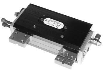
36 122 LONG-STROKE GRIPPERS GPL PRODUCT DESCRIPTION The Long-Stroke Grippers GPL are designed for gripping identical parts or parts with very different dimensions. Wide jaw travel is also ideal for contour gripping. They have an extremely robust, low-friction jaw guide in which the main forces are carried by cylindrical rollers. The pneumatic connections and proximity switches are arranged on the narrow side of the housing.
37 123 APPLICATIONS Use with proximity switches; thanks to the large stroke, interlocking gripping is possible. This enables even complicated geometries to be held.
38 124 LONG-STROKE GRIPPERS PARALLEL DOUBLE-ACTING GPL Two sizes in three or two strokes. SCOPE OF DELIVERY With clamping device for proximity switches and two exhaust throttles. SUITABLE ACCESSORIES Accessories from page 303 Quick-Set from page 1
39 125 DEFINITION OF LOAD Moy Mox Lx Lx Foy Fs Foy (F s) (F s) Foz Lz Ly Fs Foz Moz GPL GPL perm. [N] see gripping force diagram Foy perm. [N] Foz perm. [N] Lx perm. [mm] Ly perm. [mm] Lz perm. [mm] (Lx + Ly) perm. [mm] (Ly + Lz) perm. [mm] (Lz + Lx) perm. [mm] Mox perm. = (Foy. Lz) + (Foz. Ly) [Nmm] Moy perm. = (. Lz) + (Foz. Lx) [Nmm] Moz perm. = (. Ly) + (Foy. Lx) [Nmm] : Gripping force per gripper finger [N] Foy, Foz: Static forces [N] Lx, Ly, Lz: Distances of force application [mm] Mox, Moy, Moz: Static load moments [Nmm] When Mox, Moy, Moz act simultaneously, each may attain its permitted maximum.
40 126 LONG-STROKE GRIPPERS PARALLEL DOUBLE-ACTING GPL SIZE 1 GPL ) Measured at max. travel 2) Scatter of the gripper end position after 100 successive strokes under constant conditions 3) See accessories page 303 GPL-40-1 Gripping distance = stroke [mm] Opening time at 3/6 bar 1) [s] 0.18/ /0.12 Closing time at 3/6 bar 1) [s] 0.18/ /0.12 Weight GPL [kg] Mass moment of inertia Jz [kgcm 2 ] Operating pressure [bar] 3 6 Operating medium air, oiled or unoiled, filtered to 5 µm, dew point < 6 C Repeatability 2) [mm] ± 0.03 Pneumatic connection M5, with plug Ø 4 mm Speed regulation adjustable exhaust throttles Check on end position open/closed 3) inductive proximity switches Ambient: Temperature [ C] Rel. humidity < 95% (without condensation) Air purity normal workshop atmosphere Warranty 2 years from the date of delivery Maintenance none needed Mounting position any Material aluminum, steel, plastic GRIPPING FORCE DIAGRAM F S = Gripping force per gripper finger
41 R 127 European projection 40 A 17 B 4 CH-4552 DERENDINGEN GEWERBESTRASSE ± ±0.1 max. D Stroke H LZ 1) M3 8f6 2.5 LY ± LZ (E) ± ±0.02 3H8 24 (8) 3 H8 8 deep M4 5.5 deep 40 ±0.2 1) Inductive proximity switches Ø 6.5 mm, installation depth 5.5 mm H A B D E GPL GPL Ref. No. GPL GPL
42 128 LONG-STROKE GRIPPERS PARALLEL DOUBLE-ACTING GPL SIZE 2 GPL-45-2 GPL-60-2 GPL-75-2 Gripping distance = stroke [mm] Opening time at 3/6 bar 1) [s] 0.44/ / /0.36 Closing time at 3/6 bar 1) [s] 0.44/ / /0.36 Weight GPL [kg] Mass moment of inertia Jz [kgcm 2 ] Operating pressure [bar] 3 6 Operating medium air, oiled or unoiled, filtered to 5 µm, dew point < 6 C Repeatability 2) [mm] ± 0.04 Pneumatic connection M5, with plug Ø 4 mm Speed regulation adjustable exhaust throttles Check on end position open/closed 3) inductive proximity switches Ambient: Temperature [ C] Rel. humidity < 95% (without condensation) Air purity normal workshop atmosphere Warranty 2 years from the date of delivery Maintenance none needed Mounting position any Material aluminum, steel, plastic 1) Measured at max. travel 2) Scatter of the gripper end position after 100 successive strokes under constant conditions 3) See accessories page 303 GRIPPING FORCE DIAGRAM F S = Gripping force per gripper finger
43 R 129 European projection A B CH-4552 DERENDINGEN GEWERBESTRASSE ± ±0.1 max. D LZ 1) M4 10f6 3 LY ± LZ (E) ± ±0.02 (8) 4H Stroke H 4 H8 5.5 deep M5 6 deep 40 ±0.2 1) Inductive proximity switches Ø 6.5 mm, installation depth 5.5 mm H A B D E GPL GPL GPL Ref. No. GPL GPL GPL
44 130 SPECIAL ACCESSORIES FOR GPL ROTARY POSITION ENCODER ADD-ON KIT for attachement of the incremental rotary position encoders (506686, ) of the gripper case GPL to GPL-1 (size 1) to GPL-2 (size 2) 49005
45 131

46 132 UNIVERSAL ANGULAR GRIPPERS GWU/GWUI PRODUCT DESCRIPTION The Universal Angular Grippers GWU-20/GWUI-20 are designed for external gripping. The pneumatic cylinder is double-acting. The special shape of the jaw actuating bracket generates high gripping forces without self-locking when the gripper is in the closed position. The inductive proximity switches needed to scan the end positions and the compressed-air supply are arranged on the two narrow sides. This enables several grippers to be mounted side by side without limiting the accessibility to the proximity switches or compressed air supply. With jaws that open 180, the GW gripper may reduce the number of movements required to grip a part. The maximum opening angle saves a handling movement in many cases. SCOPE OF DELIVERY With clamping device for proximity switches two exhaust throttles. I versions without exhaust throttles. SUITABLE ACCESSORIES Accessories from page 303 Quick-Set from page 1
47 133 DEFINITION OF LOAD Moy Mox Moy Foy Moz Moz Lz Lx Lx Foz Ly Lx Lx Foz Foy : Gripping force per gripper finger [N] Foy, Foz: Static forces [N] Lx, Ly, Lz: Distances of force application [mm] Mox, Moy, Moz: Static load moments [Nmm] When Mox, Moy, Moz act simultaneously, each may attain its permitted maximum. If the action of Foz on the gripper jaw is displaced by Lx the closing force is affected as follows: eff = ± Foz L x Lz GWU/GWUI-16 [N] see gripping force diagram GWU/GWUI-20 Foz [N] ±250 ±400 Mox perm. = (Foy. Lz) + (Foz. Ly) [Nmm] Moy perm. = (Foz. Lx) [Nmm] Moz perm. = (. Ly) + (Foy. Lx) [Nmm] DIMENSIONS OF FINGER MOUNTING a S Lz S: Center of gravity of gripping finger a: Distance between fulcrum and center of gravity Lz: Distance between fulcrum and clamping point : Clamping force per gripping finger Gripping finger mounting on the inside of the gripper jaw Gripping finger mounting on the outside of the gripper jaw
48 134 UNIVERSAL ANGULAR GRIPPERS GWU-16/GWUI-16 Opening angle infinitely adjustable [ ] Piston diameter [mm] 16 Weight GWU/GWUI [kg] 0.27 Mass moment of inertia Jz (closed) [kgcm 2 ] 0.56 Max. cycles per minute max. 80 double stroke per minute Operating pressure [bar] 3 6 Operating medium air, oiled or unoiled, filtered to 5 µm, dew point < 6 C Repeatability at 5 bar 1) [mm] ±0.05 Check on end position open/closed 2) inductive proximity switch Pneumatic connection adjustable exhaust throttles M5, with plug Ø 4 mm Ambient: Temperature [ C] Rel. humidity < 95% (without condensation) Air purity normal workshop atmosphere Warranty 2 years from the date of delivery Maintenance after 10 mio. cycles Mounting position any Material aluminum, steel, bronze 1) At Lz = 33 [mm] End of jaw. Scatter of the gripper end position after 100 successive strokes under constant conditions 2) See accessories page 303 PERM. FINGER DIMENSIONS GWU-16/GWUI-16 m [kg] n 2 u Permissible dimensions of the individual finger m adm. [kg] n=6 n=5 n=4 n=3 u u u u GRIPPING FORCE DIAGRAM GWU-16/GWUI-16 = Gripping force per gripper finger Fs Gripping force [N] with parallel jaw Lz in [mm] Lz=30 Lz=40 Lz=50 Lz=60 Lz=70 Lz=80 Lz=90 Lz=100 Lz=110 Lz= Distance a [mm] Operating pressure [bar] CLOSING AND OPENING TIME GWU-16/GWUI-16 nu t nu: Number of closing revolutions of the exhaust throttle t: Closing and opening time [s] (90 per jaw, p = 5 bar)
49 135 European projection ) 2) 46 (17.5) f8 Ø 4.5 Lz Hholes 10 ±0.01 (5) (4) 32 ± ±0.01 Thread M3x5 mm Thread 10 ±0.1 Ø 3 H8x5 mm holes 1) 46 Ø f8 Ø 4.5 Lz ) 2) 1) Inductive proximity switches Ø 6.5 mm installation depth 6.7 mm 2) Air supply Ref. No. GWU GWUI
50 136 UNIVERSAL ANGULAR GRIPPERS GWU-20/GWUI-20 Opening angle infinitely adjustable [ ] Piston diameter [mm] 20 Weight GWU/GWUI [kg] 0.43 Mass moment of inertia Jz (closed) [kgcm 2 ] 1.34 Max. cycles per minute max. 80 double stroke per minute Operating pressure [bar] 3 6 Operating medium air, oiled or unoiled, filtered to 5 µm, dew point < 6 C Repeatability at 5 bar 1) [mm] ±0.05 Check on end position open/closed 2) inductive proximity switch Pneumatic connection adjustable exhaust throttles M5, with plug Ø 4 mm Ambient: Temperature [ C] Rel. humidity < 95% (without condensation) Air purity normal workshop atmosphere Warranty 2 years from the date of delivery Maintenance after 10 mio. cycles Mounting position any Material aluminum, steel, bronze 1) At Lz = 38 [mm] End of jaw. Scatter of the gripper end position after 100 successive strokes under constant conditions 2) See accessories page 303 PERM. FINGER DIMENSIONS GWU-20/GWUI-20 m [kg] GRIPPING FORCE DIAGRAM GWU-20/GWUI n 2 u Permissible dimensions of the individual finger m adm. [kg] n=6 n=5 n=4 n=3 u u u u = Gripping force per gripper finger Gripping force [N] with parallel jaw Lz in [mm] L z=30 L z=40 L z=50 L z=60 L z=70 L z=80 z=90 z=100 z=110 L z= Distance a [mm] Operating pressure [bar] CLOSING AND OPENING TIME GWU-20/GWUI-20 nu t nu: Number of closing revolutions of the exhaust throttle t: Closing and opening time [s] (90 per jaw, p = 5 bar)
51 137 European projection ) (17.5) 25 GWU ) f8 Ø 4.5 Lz Holes 16 ±0.01 (4.5) (5) 30 ± ±0.01 Thread M4x7 mm Thread 16 ±0.1 Ø 4 H8x6 mm holes 56 Ø40 25 GWUI-20 1) f8 Ø 4.5 Lz ) 2) 1) Inductive proximity switches Ø 6.5 mm installation depth 8.7 mm 2) Air supply Ref. No. GWU GWUI
52 more than technology MONTECH AG Gewerbestrasse 12, CH-4552 Derendingen Fon , Fax
PWG-S. Application example. Pneumatic 2-Finger Angular Gripper Universal Gripper. Sizes. Gripping moment 5.98 Nm Nm. Weight 0.21 kg 1.
 PWG-S Sizes 40 80 Weight 0.21 kg 1.2 kg Gripping moment 5.98 Nm 50.82 Nm Angle per jaw 20 Workpiece weight 1.1 kg 4.8 kg Application example Rotating/gripping combination for flexible handling of sheet
Gripping rotary modules
 Gripping rotary modules Gripping rotary modules GRIPPING ROTARY MODULES Series Size Page Gripping rotary modules RP 314 RP 1212 318 RP 1216 322 RP 1520 326 RP 2120 330 RP 2128 334 RC 338 RC 1212 342 RC
Pneumatic Grippers Swivel Modules
 Pneumatic Grippers Swivel Modules Pneumatic Grippers Swivel Modules ROTARY GRIPPERS MODULES Series Size Page GSM 748 Parallel Grippers GSM-P 750 GSM-P 32 754 GSM-P 40 760 GSM-P 50 766 GSM-P 64 772 Centric
LGP. Application example. Pneumatic 2-Finger Parallel Gripper Universal Gripper. Sizes. Gripping force 26 N 1090 N. Weight 0.03 kg 1.
 LGP Sizes 8 4 Weight.3 kg 1.6 kg 26 N 19 N Stroke per finger 2 mm 13 mm Workpiece weight.13 kg 4.2 kg Application example Pneumatic double transfer unit 2-Finger Parallel Gripper LGP Universal Rotary Actuator
MPG-plus. Application example. Pneumatic 2-Finger Parallel Gripper Gripper for small components. Gripping force 38 N 175 N. Sizes
 MPG-plus Sizes 25 40 Weight 0.06 kg 0.24 kg Gripping force 38 N 175 N Stroke per finger 3 mm 6 mm Workpiece weight 0.19 kg 0.7 kg Application example Pneumatically driven, dual-axis pick-and-place machine
SPG. Application example. Pneumatic 2-Finger Parallel Gripper Heavy-load Gripper. Weight 35 kg. Stroke per finger 100 mm.
 SPG Size 100 Weight 35 kg 10,000 N Stroke per finger 100 mm Workpiece weight 50 kg Application example Gripper unit for heavy V8 engine blocks. SPG 100 2-Finger Heavy-load Gripper 446 www.schunk.com SPG
LGR. Application example. Pneumatic 2-Finger Radial Gripper Universal Gripper. Sizes. Gripping moment 0.3 Nm 15 Nm. Weight 0.07 kg 1.
 LGR Sizes 10 40 Weight 0.07 kg 1.27 kg Gripping moment 0.3 Nm 15 Nm Angle per jaw 90 Workpiece weight 0.07 kg 1066 kg Application example Rotational adjustment for reorientation of workpieces 2-Finger
GWB Pneumatic 2-Finger Radial Gripper Universal Gripper Sizes Weight Gripping moment Opening angle per finger Workpiece weight
 GWB Sizes 34.. 100 Weight 0.14 kg.. 3.5 kg Gripping moment 2.1 Nm.. 127 Nm Opening angle per finger 10.. 90 Workpiece weight 0.3 kg.. 6.0 kg Application example Rotating/gripping combination for handling
Description Total stroke Maximum Recommended Page in mm gripping force in N workpiece weight in kg
 Overview parallel gripper Description Total stroke Maximum Recommended Page in mm gripping force in N workpiece weight in kg Version 1 2 1 2 1 2 RRP-A 64 12 6 240 450 1,2 2,2 26 80 16 8 380 700 1.9 3.5
PFH. Application example. Pneumatic 2-Finger Parallel Gripper Long-stroke Gripper. Weight 2.65 kg 12.6 kg. Gripping force 630 N 2950 N
 PFH www.comoso.com Sizes 30 50 Weight 2.65 kg 12.6 kg Gripping force 630 N 2950 N Stroke per finger 30 mm 100 mm Workpiece weight 3.15 kg 13 kg Application example Assembly unit for intermediate sleeves
Gripping modules Pneumatic 2-finger parallel gripper Long-stroke gripper for small components Gripping force 120 N..
 GM Sizes 85.. 205 Mass 0.48 kg.. 2.7 kg 120 N.. 595 N Stroke per finger 16 mm.. 30 mm Workpiece weight, force-fit gripping Up to 2.3 kg Application example 3 5 3 4 2 5 2 1 1 Pneumatic double pick & place
Pneumatic Gripping Modules. Pneumatic 2-Finger Radial Grippers
 Pneumatic Gripping Modules Pneumatic 2-Finger Radial Grippers Pneumatic Gripping Modules Pneumatic 2-Finger Radial Grippers 2-FINGER RADIAL GRIPPERS Series Size Page Universal Grippers GWB 676 GWB 34 680
PFH. Application example. Pneumatic 2-Finger Parallel Grippers Long-stroke Grippers. Sizes Gripping force 510 N N
 PFH Sizes 30.. 50 Weight 2.65 kg.. 9.7 kg Gripping force 510 N.. 2650 N Stroke per finger 30 mm.. 50 mm Workpiece weight 2.55 kg.. 11.5 kg Application example Assembly unit for intermediate sleeves in
SWG. Application example. Pneumatic 2-Finger Angular Gripper Angular Gripper for Small Components. Sizes Gripping moment 0.01 Nm.. 2.
 SWG Sizes 10.. 50 Weight 2.5 g.. 213 g Gripping moment 0.01 Nm.. 2.8 Nm Opening angle per finger 15 Workpiece weight 0.007 kg.. 0.45 kg Application example Triple transfer unit for packaging with small
PSH (inch version) Application example. Pneumatic 2-Finger Parallel Grippers Long-stroke Grippers. Stroke per finger 14 mm.. 64 mm. Sizes 22..
 Application example. Pneumatic 2-Finger Parallel Grippers Long-stroke Grippers. Stroke per finger 14 mm.. 64 mm. Sizes 22..") PSH (inch version) Sizes 22.. 52 Weight 0.77 kg.. 8.05 kg Gripping force 320 N.. 1760 N Stroke per finger 14 mm.. 64 mm Workpiece weight 1.60 kg.. 8.80 kg Application example Rapid loading and unloading
PSH (inch version) Sizes 22.. 52 Weight 0.77 kg.. 8.05 kg Gripping force 320 N.. 1760 N Stroke per finger 14 mm.. 64 mm Workpiece weight 1.60 kg.. 8.80 kg Application example Rapid loading and unloading
PSH. Application example. Pneumatic 2-Finger Parallel Gripper Long-stroke Gripper. Stroke per finger 14 mm.. 64 mm. Sizes
 PSH Sizes 22.. 52 Weight 0.77 kg.. 8.05 kg 320 N.. 1760 N Stroke per finger 14 mm.. 64 mm Workpiece weight 1.60 kg.. 8.80 kg Application example Rapid loading and unloading unit on a swivel head base.
LGZ. Application example. Pneumatic 3-Finger Centric Gripper Universal Gripper. Sizes. Gripping force 120 N 1470 N. Weight 0.1 kg 0.
 LGZ Sizes 16 5 Weight.1 kg.99 kg 12 N 147 N Stroke per finger 3 mm 7 mm Workpiece weight.6 kg 5.7 kg Application example Pneumatic transfer unit for round components 3-Finger Centric Gripper LGZ Linear
Sizes Weight Gripping force Stroke per finger Workpiece weight Pieces : kg N mm kg
 MPG-plus Sizes Weight Gripping force Stroke per finger Workpiece weight Pieces : 7 0.06.. 0.63 kg 25.. 350 N 1.5.. 10 mm 0.19.. 1.25 kg Application example Pneumatically driven, dual-axis pick-andplace
PGN. Application example. Pneumatic 2-Finger Parallel Grippers Universal Grippers. Gripping force 100 N N. Sizes
 PGN Sizes 50.. 380 Weight 0.125 kg.. 28.0 kg Gripping force 100 N.. 15100 N Stroke per finger 2 mm.. 45 mm Force-fit gripping 0.5 kg.. 75.0 kg Application example Horizontal turning station with 180 reorientation
LGP Pneumatic 2-Finger Parallel Gripper Universal Gripper Sizes Weight Gripping force Stroke per finger Workpiece weight
 LGP Sizes 8.. 4 Weight.34 kg.. 1.5 kg 27 N.. 19 N Stroke per finger 2 mm.. 13 mm Workpiece weight.65 kg.. 2.5 kg Application example pneumatic double transfer unit 2-Finger Parallel Gripper LGP 2 Universal
DPZ-plus. Application example. Pneumatic 3-Finger Centric Grippers Sealed Grippers. Gripping force 520 N N. Sizes
 DPZ-plus Sizes 64.. 200 Weight 0.62 kg.. 20.1 kg Gripping force 520 N.. 16800 N Stroke per finger 3 mm.. 25 mm Workpiece weight 2.6 kg.. 60.0 kg Application example Insertion tool for assembling small
Cost effective. Smooth. Reliable. LOG Internal Hole Gripper
 LOG Cost effective. Smooth. Reliable. LOG Internal Hole Gripper Light gripper made of very resistant polyamide with closed diaphragm system Field of Application Particularly suited to highly dynamic applications
PZN-plus. Application example. Pneumatic 3-Finger Centric Gripper Universal Gripper. Sizes Gripping force 580 N..
 PZN-plus Sizes 40.. 300 Weight 0.43 kg.. 43.5 kg Gripping force 580 N.. 38000 N Stroke per finger 3 mm.. 35 mm Workpiece weight 2.9 kg.. 190 kg Application example Insertion tool for assembling small to
Product Information. Gripper for small components MPG-plus 16
 Product Information MPG-plus 16 MPG-plus More powerful. Faster. Longer fingers. MPG-plus gripper for small components 2-finger parallel gripper with smooth roller guides of the base jaws Field of application
Micro grippers HGPM/HGWM
 HGPM/HGWM Miniaturised and optimised for assembly tasks Versatile 2004/10 Subject to change Products 2004/2005 1 / 1 HGPM/HGWM Key features HGWM HGPM 1 2 3 4 1 2 3 4 System product for handling and assembly
ORG. Application example. Special Grippers O-ring Assembly Gripper. Weight 1.35 kg. Ring diameter O.D. Assembly appr.ø 5 mm.. ø 160 mm.
 Sizes 85 Weight 1.35 kg Ring diameter O.D. Assembly appr.ø 5 mm.. ø 160 mm Ring diameter I.D. Assembly appr. ø 10 mm.. ø 120 mm Application example Automatic machine for the internal or external assembly
OPERATING INSTRUCTIONS
 Handling Components OPERATING INSTRUCTIONS Intermediate stop: (For use with rotary units DAP-3) DZA-3 Issue: 507 269 12.8.01 Contents Important information EU Certificate of conformity (CE)...1 Scope of
High flow rate. Cost effective. Compliant. Gripper with GSW-B Shaft Interface and Compensation Unit
 GSW-B-AGE High flow rate. Cost effective. Compliant. Gripper with GSW-B Shaft Interface and Compensation Unit PGN-plus / PZN-plus universal gripper with shaft interface GSW-B and AGE compensation unit
PZN-plus. Application example. Pneumatic 3-Finger Centric Gripper Universal Gripper. Sizes. Gripping force 255 N N. Weight 0.
 PZN-plus Sizes 40 300 Weight 0.13 kg 46 kg Gripping force 255 N 35500 N Stroke per finger 2 mm 35 mm Workpiece weight 1.3 kg 127.5 kg Application example Insertion tool for assembling small to mediumsized
OPERATING INSTRUCTIONS
 Handling Components OPERATING INSTRUCTIONS Grippers: GPS-1 to GPS-4 GPSI-1 to GPSI-4 GPSL-1 to GPSL-4 Edition: 506 442 06.2008 Contents Important information EU Declaration of Conformity (EC)...1 Scope
Product Information. Gripper for small components MPG 20
 Product Information MPG 20 MPG Precise. Compact. Reliable. MPG gripper for small components 2-finger parallel gripper with smooth roller guides of the base jaws Field of application Gripping and moving
Parallel grippers HGPM, micro
 Key features G6: G8: G9: stroke compensation clamping spigot flange mounting At a glance Compact, handy design With open or closed gripper jaws Versatility thanks to externally adaptable gripper fingers
Product Information. Gripper for small components MPC
 Product Information MPC MPC Easy. Economical. Cost-effective. MPC Easily built up 2-finger parallel gripper with good price-performance ratio Field of application Gripping of small to mid-sized workpieces
Single and double acting, magnetic, self-centering Bores: ø 16, 20, 25, 32, 40 mm
 > Series CGPT self-centering parallel grippers with T-guide Series CGPT self-centering parallel grippers with T-guide Single and double acting, magnetic, self-centering Bores: ø 6, 20, 25, 32, 40 mm New
GRIPPERS SERIES P3 - P12 ACTUATORS
 GRIPPERS SERIES P3 - P12 1 GRIPPER WITH TWO PARALLEL JAWS, SERIES P3 GRIPPER WITH TWO PARALLEL JAWS, SERIES P3 Parallel double-acting two-jaw gripper, with either internal or external clamping. Aluminum
Product Information. Tolerance compensation unit TCU-Z
 Product Information TCU-Z TCU-Z Compact. Flexible. Productive. TCU-Z tolerance compensation unit The TCU is compensated on the basis of elastomers that compensate in all three directions, enabling them
Technical Data Sheet TI-F50 Locking Units series KFH
 English translation of German original Locking Units series KF Further important practical advice is given in Operating Manual BA-F50., Rod diameter 18 mm 50 mm øz 8 L 2 6 x 6 0 min. 4x30 KF 18 to KF 32,
GX-S. 2-jaw self centering radial pneumatic gripper (series GX-S) GX-S
 GX-S") GX-S 2-jaw self centering radial pneumatic gripper (series GX-S) Double acting. Very high gripping force at the end of the stroke. Long life and reliability, maintenance free. Various options for fastening.
GX-S 2-jaw self centering radial pneumatic gripper (series GX-S) Double acting. Very high gripping force at the end of the stroke. Long life and reliability, maintenance free. Various options for fastening.
Grippers with Spindle Interface
 Weight 0.8 kg.. 3.9 kg Gripping force 70 N.. 1200 N Stroke per finger 4 mm.. 10 mm Layout of the work area in the machining center Example of a handling and machining sequence: 1. Gripper removes blank
2-jaw self-centering pneumatic parallel gripper (series SX)
") SX 2-jaw self-centering pneumatic parallel gripper (series SX) Double acting (normally closed on request). High gripping force. Protection class: IP67. Double O-Ring sealing on the columns. Suitable for
SX 2-jaw self-centering pneumatic parallel gripper (series SX) Double acting (normally closed on request). High gripping force. Protection class: IP67. Double O-Ring sealing on the columns. Suitable for
Angle grippers HGWM, micro
 Key features G6: G7: G8: with stroke compensation with male thread with clamping spigot At a glance Compact, handy design With open or closed gripper jaws Versatility thanks to externally adaptable gripper
GS - Parallel Gripper
 11: Double acting Patented backlash adjusting system. Long life and reliability, maintenance free. Different options for fastening. Optional magnetic sensors available on page 517. Spring closed (-NC)
2-JAW PARALLEL GRIPPERS INSTALLATION SIZE GPP5006IL
 2-JAW PARALLEL GRIPPER INTALLATION IZE GPP006IL PRODUCT PECIFICATION Gripping force diagram Forces and moments Displays static forces and moments that can also have an effect, besides the gripping force.
PGN-plus. Universal Gripper Universal 2-finger parallel gripper with large gripping force and high maximum moments thanks to multi-tooth guidance.
 PGN-plus Sizes 40 380 Weight 0.08 kg 39.5 kg Gripping force 123 N 21150 N Stroke per finger 2 mm 45 mm Workpiece weight 0.62 kg 80.5 kg Application example Pick-and-place unit for light to medium-weight
Reliable. Fully encapsulated. Loadable. DPG-plus Sealed Gripper
 DPG-plus Reliable. Fully encapsulated. Loadable. DPG-plus Sealed Gripper Despite the high moment load of the base jaws, this sealed 2-finger parallel gripper conforms to the IP67 requirements and does
Wide opening parallel grippers Series CGLN
 CATALOGUE > s 202 Wide opening parallel grippers Series CGLN > Grippers Series CGLN Magnetic Sizes: ø 0-6 - 20-25 - 32 mm» High flexibility during mounting» High grip force» Rack and pinion synchronized
Opening Angle 76º 30º [337] 45º 76º 30º [213] 45º 76º 30º [169] 45º 76º 30º [337] 45º 76º 30º [337] 45º 76º 30º [128] 45º 76º 30º [404] 45º 76º 30º
![Opening Angle 76º 30º [337] 45º 76º 30º [213] 45º 76º 30º [169] 45º 76º 30º [337] 45º 76º 30º [337] 45º 76º 30º [128] 45º 76º 30º [404] 45º 76º 30º](/thumbs/81/84065106.jpg "Opening Angle 76º 30º [337] 45º 76º 30º [213] 45º 76º 30º [169] 45º 76º 30º [337] 45º 76º 30º [337] 45º 76º 30º [128] 45º 76º 30º [404] 45º 76º 30º") 17.22 Picture Force N [lbs] Opening Angle Weight Opening/closure time min 84A3-310000000 84A3X310000000 84A3Y310000000 84A3Z310000000 60º 1,35 84A3-0000000 84A3X0000000 950 84A3Y0000000 [213] 84A3Z0000000
17.22 Picture Force N [lbs] Opening Angle Weight Opening/closure time min 84A3-310000000 84A3X310000000 84A3Y310000000 84A3Z310000000 60º 1,35 84A3-0000000 84A3X0000000 950 84A3Y0000000 [213] 84A3Z0000000
Reliability and flexibility in a compact design
 Catalogue Handling Reliability and flexibility in a compact design Modern industrial processes are now characterized by an ever increasing amount of automation. Where very high performance is required,
Heavy-duty three-point grippers HGDT
 Key features At a glance The force generated by the linear motion is translated into the gripper jaw movement via a force-guided triple wedge mechanism. This also guarantees synchronous movement of the
Bores: ø 10, 16, 20, 25, 32 mm
 > Series CGLN wide opening parallel grippers CATALOGUE > Release 8.8 Series CGLN wide opening parallel grippers New version Bores: ø 0, 6, 20, 25, 32 mm»» High installation versatility»» Rack and pinion
MPRM1690 MPRM2590 MPRM3290
 Pinze elettriche radiali a 2 griffe 2-jaw radial electric grippers MPRM 2-jaw radial self-centering electric gripper Plug & play user friendly gripper. No electricity consumption when gripper is engaged.
Double Acting Models Part# GW-10 GW-16 GW-20 GW-25 Quick# Price $95.00 $ $ $ Medium
 11: Double acting Long life and reliability, maintenance free. Different options for fastening. Optional proximity magnetic sensors available on page 527. Spring closed (-NC) or spring open (-NO) option.
Pressure maintenance valve SDV-P / SDV-P-E
 Translation of the original manual Pressure maintenance valve SDV-P / SDV-P-E Assembly and Operating Manual Superior Clamping and Gripping Imprint Imprint Copyright: This manual remains the copyrighted
Parallel grippers HGPM, micro
 Key features G6: G8: G9: with stroke compensation with clamping spigot with flange mounting At a glance Compact, handy design With open or closed gripper jaws Versatility thanks to externally adaptable
PRP. Pneumatic parallel gripper with rotator PRP
 PRP Pneumatic parallel gripper with rotator Compatible with the G-mix system. Selectable rotation angle. Gripper with integrated rotator: the four sensors and the four hoses do not rotate. Optional magnetic
Product Information. Gripper for small components RH 905
 Product Information RH 905 RH cost-effective. Easy. Economical. RH gripper for small components The RH series is a cost-efficient gripping system, which is particularly suitable for simple cases of application.
Filtered compressed air, lubricated or non-lubricated. Maximum torque on each jaw on opening at 87 psi 3.1 in-lbf 10.6 in-lbf 20.
 2-JAW SELF-CENTERING RADIAL PNEUMATIC GRIPPER (SERIES ) Double-acting. High gripping force at the end of the stroke. Maintenance-free long life and reliability. Various options for fastening. Optional
Product Information. Sealed universal gripper DPG-plus 100
 Product Information 100 Reliable. Fully encapsulated. Loadable. Sealed gripper Despite the high moment load of the base jaws, this sealed 2-finger parallel gripper meets the IP67 requirements, and does
Series CGZT three-jaw grippers with T-guide
 Series CGZT three-jaw grippers with T-guide New Single and double acting, magnetic, self-centering Sizes: 40, 50, 64, 80, 100, 125, 160 mm The new Series CGZT pneumatic grippers, thanks to the use of a
3-JAW CONCENTRIC GRIPPERS INSTALLATION SIZE GPD5006IL
 3-JAW CONCENTRIC GRIPPER INTALLATION IZE GPD006IL PRODUCT PECIFICATION Gripping force diagram Forces and moments Displays static forces and moments that can also have an effect, besides the gripping force.
Locking Units. Technical Information TI-F10. Locking by springs / releasing by pressure Types KFH, KFP and others
 Technical Information SITEMA - ocking Units Hydraulic or pneumatic actuation English translation of German original TI-F0-EN-0/06 Technical Information TI-F0 ocking Units Holding in both load directions
2-JAW SELF-CENTERING PARALLEL PNEUMATIC GRIPPER (SERIES SZ)
") 2-JAW SELF-CENTERING PARALLEL PNEUMATIC GRIPPER (SERIES ) Double-acting. Spring closed (upon request). Patented self-centering system. Multiple mounting and porting options. Optional magnetic sensors.
2-JAW SELF-CENTERING PARALLEL PNEUMATIC GRIPPER (SERIES ) Double-acting. Spring closed (upon request). Patented self-centering system. Multiple mounting and porting options. Optional magnetic sensors.
Technical Information TI-S10 Safety Locks. 2 Function. Contents
 English translation of German original TI-S1 Safety Locks high holding force by self-reinforcing clamping hydraulic or pneumatic actuation for static loads For further information on technical data please
2-JAW SELF-CENTERING PARALLEL PNEUMATIC GRIPPER (SERIES HS)
") HS 2-JAW SELF-CENTERING PARALLEL PNEUMATIC GRIPPER (SERIES HS) Designed for high-speed machines. Very short closing/opening times. Lightweight. Maintenance-free long life and reliability. Long stroke.
HS 2-JAW SELF-CENTERING PARALLEL PNEUMATIC GRIPPER (SERIES HS) Designed for high-speed machines. Very short closing/opening times. Lightweight. Maintenance-free long life and reliability. Long stroke.
2-finger parallel gripper KTG 50
 Translation of the original manual 2-finger parallel gripper KTG 50 Assembly and operating manual Superior Clamping and Gripping Imprint Imprint Copyright: This manual remains the copyrighted property
Series CGCN self-centering three-jaw grippers with T-guide
 HANDLING AND VACUUM 2019 GRIPPERS > Series CGCN self-centering three-jaw grippers with T-guide New Double acting, magnetic Sizes: 50, 64, 80, 100, 125 mm The new Series CGCN pneumatic grippers are available
RG2 Gripper Datasheet Version 1.6
 RG2 Gripper Datasheet Version 1.6 The RG2 gripper is a flexible electric gripper specially designed for robots from Universal Robots. The long stroke allows the gripper to handle a variety of object sizes.
1Robust, lightweight housing - hard coated aluminium alloy. 2Energy supply - air connection available on several sides
 3-Jaw Concentric eries GD3 pneumatic Product information: Extremely robust T-lot guide for maximum forces and moments capacity Gripper jaws made of ground surfaced and hardened steel ensuring long lasting
Flow and check valves Logic valves series 551. Brochure
 Flow and check valves Logic valves series 551 Brochure 2 Flow and check valves Logic valves series 551 3/2-directional valve, low pressure operated Qn = 2-120 l/min 3 3/2-directional valve, Qn = 120 l/min
Maximum 0.85 MPa pressure setting Long-life, high flow perfect for balancer applications
 Outstanding performance in extremely low pressure and low pressure ranges from 0.003 to. Realizing high performance, energy saving, and compact size. Realize precise pressure control in a pressure range
Technical Data Sheet TI-F52 Locking Unit KFHL Certified by Lloyd s Register
 English translation of German original TI-F52 Locking Unit KFHL Certified by Lloyd s Register For a detailed functional description refer to Technical Information TI-F10. Further important practical advice
Air preparation units
 Overview Description Page Characteristics Dimensions Order instructions Type overview unit three-piece 44, 45, 48 52 6 unit two piece 44, 45, 48 52 6 Filter-regulator 44, 45, 48 53 6 Filter-water-separator
pneumatic power clamps
 pneumatic power clamps Features Király Trading KFT H-1151 Budapest Mogyoród útja 12-14 E-mail:_agi@kiralytrading.hu Your requirements Power element of machines, tools and devices for the following applications:
Hand lever valves VHER
 Hand lever valves VHER Hand lever valves VHER Key features Powerful Flexible Practical -M- Flow 170 3800 l/min 4/3-way valve mid-position closed mid-position exhausted mid-position pressurised Connections:
Dual displacement motor A10VM Plug-in dual displacement motor A10VE for open and closed circuit applications
 Replaces: 04.95 Dual displacement motor 10VM Plug-in dual displacement motor 10VE for open and closed circuit applications Size 28-60 Series 5 Nominal pressure 280 bar Peak pressure 350 bar 10VM Contents
Type 4708 Supply Pressure Regulator
 Type 478 Pressure Regulator Application pressure regulators used to provide pneumatic measuring and control equipment with a constant air supply Set point ranges. to. bar ( to 4 psi). to bar (8 to 9 psi)
Position locking powerful chuck. CKL2-*-HC Series CKL2-40CS-HC CKL2-50CS-HC CKL2-63CS-HC CKL2-80CS-HC Compressed air to
 RV* FH1 G G B FH Specifications Descriptions Cylinder bore size Working fluid Max. working pressure Min. working pressure Ambient temperature Port size Operational stroke length Rod diameter Capacity of
FIPA End-of-Arm-Tooling
 213.GR6-ER English February 213 FIPA End-of-Arm-Tooling Addendum Version 1 www.fi pa.com Editorial Only those who think ahead stay ahead Competence End-of-Arm-Tooling Based in Ismaning near Munich, FIPA
Type 4708 Supply Pressure Regulator
 Type 478 Pressure Regulator Application pressure regulator used to provide pneumatic measuring and control equipment with a constant air supply Set point ranges. to.6 bar ( to 4 psi) or. to 6 bar (8 to
RCP5W-RA Series. www. r o b o c y lind e r. d e. Dust-/Splash-/Water-proof RoboCylinder Rod Type with Battery-less Absolute Encoder
 Product Data Sheets RCPW-RA RoboCylinder Brochure Extract GB Dust-/Splash-/Water-proof RoboCylinder Rod with Battery-less Absolute Encoder RCPW-RA Series www. r o b o c y lind e r. d e Specification Table
Design Guide MSW from M20 to M70. Original version of the design guide
 Page 1 of 11 Original version of the design guide For Series Components Spieth locknuts (precision locknuts) MSW 20.28 MSW 20.40 MSW 25.28 MSW 25.40 MSW 30.28 MSW 30.44 MSW 35.28 MSW 35.44 MSW 40.28 MSW
![[Instruments for vacuum measurement, checking and adjustment] 3](/thumbs/94/121874202.jpg "[Instruments for vacuum measurement, checking and adjustment] 3")
Electropneumatic Positioner and Pneumatic Positioner Type 3760 JIS
 Electropneumatic Positioner and Pneumatic Positioner Type 3760 Application Single-acting positioners for direct attachment to pneumatic control valves. Supplied with an electric input signal of 4 to 20
Type 4708 Supply Pressure Regulator
 Type 708 Pressure Regulator Application pressure regulator used to provide pneumatic measuring and control equipment with a constant air supply Set point range 0.5 to bar (8 to 90 psi) The pressure regulator
Bellows actuator EB Key features
 Bellows actuator B Bellows actuator B Key features Key features Suitable for use in harsh, dusty ambient conditions Can be used under water Sturdy design Large forces range from 1 50 KN Low installation
Assembly and Operating Manual GAP 2-finger angular / parallel gripper
 Translation of the Original Manual Assembly and Operating Manual GAP 2-finger angular / parallel gripper Imprint Imprint Copyright: This manual is protected by copyright. The author is SCHUNK GmbH & Co.
Components for air preparation and pressure adjustment. OUT port position ( ) connected Rear side. of IN port. Air tank. directly.
 connected Rear side. of IN port. Air tank. directly.") Components preparation and pressure adjustment ABP Overview ABP is a component that enables boosting by s only up to twice primary pressure (.0MPa max.) in combination with using air tank but not using
Components preparation and pressure adjustment ABP Overview ABP is a component that enables boosting by s only up to twice primary pressure (.0MPa max.) in combination with using air tank but not using
Fixed Displacement Plug-In Motor A2FE
 www.phphyds.com Series 6, axial tapered piston, bent axis design for mounting in mechanical gearboxes Sizes 28...355 Nom. Pressure up to 400 bar Peak Pressure up to 450 bar he fixed displacement plug-in
4/2 way Pneumatic Solenoid Valve
 4/2 way Pneumatic Solenoid Valve Compact design Push-over solenoid coil Exhaust air can be regulated Tube, threaded and sub-base connections Type combined with Seat valve version Type 2508 Type 2510/11
INSTALLATION AND OPERATING INSTRUCTIONS:
 1. Applicable documents NOTE: The following documents are available to download on our website. Only the documents currently available on the website are valid Catalogue Drawings, performance data, information
Hydraulic comparison test pump Models CPP1000-X, CPP1600-X
 Calibration Hydraulic comparison test pump Models CPP1000-X, CPP1600-X WIKA data sheet CT 91.12 for further approvals see page 2 Applications Calibration service companies and service industry Maintenance
Proportional pressure regulators VPPE
 Proportional pressure regulators VPPE Proportional pressure regulators VPPE Product range overview Function Version Pneumatic connection Proportional pressure regulator Nominal size for pressurisation/
Fixed Displacement Motor A4FM
 Fixed Displacement Motor 4FM RE 91 12/4. replaces: 3.95 and RE 91 1 for open and closed circuits Sizes 22...5 Series 1, Series 3 Nominal pressure up to bar Peak pressure up to 45 bar Index Features 1 Ordering
![[Graphic Division] 10](/thumbs/89/99951971.jpg "[Graphic Division] 10")
3/2-way valve, Series CD07 Qn= 1400 l/min pipe connection compressed air connection output: G 1/4 - M14x1,5 suitable for ATEX
 /-way valve, Series CD07 Version Spool valve, zero overlap Sealing principle soft sealing Working pressure min./max. -0.95 bar / 0 bar Ambient temperature min./max. -5 C / +80 C Medium temperature min./max.
INFORMATION SHEET: SERIES GRC PARALLEL GRIPPERS
 INFORMATION SHEET: SERIES GRC PARALLEL S IMPORTANT INFORMATION DO NOT DISCARD! Use this formation sheet to assist with gripper stallation and setup. File with matenance or mache documentation. TO ORDER
CKL2 Series. Powerful chuck. Operational stroke length: 5, 6, 8, 10, 12, 16, 20, 23mm. Specifications. Switch specifications
 RV* FH1 G B FH G A S Specifications Descriptions Size Cylinder bore size mm Working fluid Max. working pressure MPa Min. working pressure MPa Ambient temperature C Port size Operational stroke length mm
Mounting and Operating Instructions EB 3007 EN. Self-operated Pressure Regulators. Differential Pressure Regulators (opening) Type Type 42-25
 Type Type 42-25") Self-operated Pressure Regulators Differential Pressure Regulators (opening) Type 42-20 Type 42-25 Type 42-20 Differential Pressure Regulator Type 42-25 Differential Pressure Regulator Mounting and Operating
Self-operated Pressure Regulators Differential Pressure Regulators (opening) Type 42-20 Type 42-25 Type 42-20 Differential Pressure Regulator Type 42-25 Differential Pressure Regulator Mounting and Operating
Directional valves Pneumatically operated Series CD07. Brochure
 Series CD07 Brochure 2 Bosch Rexroth AG Pneumatics Series CD07 2/2-way valve, Series CD07 Qn = 1400 l/min pipe connection compressed air connection output: M14x1,5 suitable for ATEX 3 3/2-way valve, Series
VPPL VARIABLE DISPLACEMENT AXIAL-PISTON PUMPS FOR INTERMEDIATE PRESSURE SERIES 10
 / ED VPPL VARIABLE DISPLACEMENT AXIAL-PISTON PUMPS FOR INTERMEDIATE PRESSURE SERIES OPERATING PRINCIPLE The VPPL are variable displacement axial-piston pumps with variable swash plate, suitable for applications