ModuSat TP Twin Plate Satellite Heating Unit
|
|
|
- Oscar Potter
- 5 years ago
- Views:
Transcription
1372 722277 E. technical@evinox.co.uk W. www.evinox.co.uk 2551390A")
1 ModuSat TP Twin Plate Satellite Heating Unit Installation, Commissioning and Servicing Instructions Evinox Ltd T. +44 (0) E. W A
2 Contents 1 GENERAL INFORMATION Warnings Symbols Safety Instructions TECHNICAL FEATURES Typical Schematic Principle (All Top Connections Connection configurations Dimensions Technical Features INSTALLATION Recommended handling procedure ModuSat TP positioning Checks before connecting the ModuSat TP Hydraulic Connections Use of Pre installation Rig Wall Fixing Pressure Independent Control Valve (PICV) Adjustment 21 4 PRIMARY AND SECONDARY CIRCUIT Water treatment Cleaning Precautions Bionibal Flushing Bypass ELECTRIC CONNECTIONS Modusat Wiring Connections ModuSat Connection Board (Visible once the cover is removed) Room controller connections Typical ModuSat Electric Wiring Diagram (Single Room Controller) Typical ModuSat Electric Wiring Diagram with 2 Zone Control (2 Room Controllers) 35 2
3 5.6 Typical Wiring Diagram with 3rd Party Room Stat 36 6 COMMISSIONING Initial Commissioning Procedure Apartment Circuit Balancing Use of the commissioning switch Adjustment of TMV Pump Start up Wilo PWM Pump Warranty 42 3
4 1 GENERAL INFORMATION 1.1 Warnings The ModuSat unit requires mains electrical connections and connection to the primary, low temperature hot water system and mains cold water supply to function. A pre-installation rig is available to the installer to help position and space the pipe connections to the unit during first fix, prior to the ModuSats being delivered to site. Installation must be carried out by a competent engineer in line with current regulations. Failure to read and follow the instructions provided within this document may cause potential injury or failure of the equipment. Therefore it is advised that the installer reports any equipment faults or defects to an authorised Evinox representative. Any modifications or adjustments carried out without EVINOX official authorisation will invalidate the warranty and absolves Evinox from any liability. Evinox has the right to make any changes or modifications to the products without prior notice. 1.2 Symbols Follows a list of symbols used in this manual: IMPORTANT NOTE REGARDING CORRECT INSTALLATION CAUTION! IMPORTANT NOTE REGARDING PERSONAL SAFETY AND CARE CAUTION! DANGER OF ELECTRICAL SHOCK! 1.3 Safety Instructions All installation and maintenance operations must be carried out by competent engineers according to current regulations In case of water leaks: Disconnect the electric power supply Slowly close the main water isolation valves to the unit Inform Evinox or approved Evinox engineer We recommend the unit is checked at least once a year by an authorised maintenance engineer. If the unit is subject to excessively heavy usage or non domestic installations (for example in a light commercial environment), we recommend having it checked more than once per year. TP. Disconnect the electrical supply prior to starting any work on a ModuSat 4


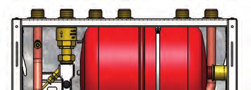
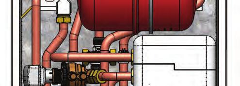
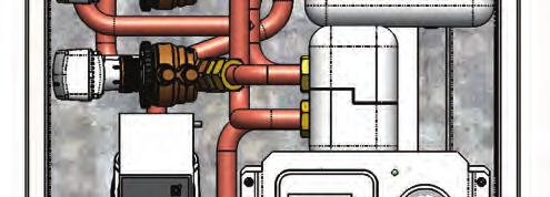
5 ModuSat TP Top Connections 5
6 2 TECHNICAL FEATURES 2.1 Typical Schematic Principle (All Top Connections) ModuSat TP 40-10, & Components A Primary / DH flow B Primary / DH return C Domestic cold water Inlet D Domestic hot water outlet E Secondary / Apartment heating flow F Secondary / Apartment heating return G Connection for safety discharge Primary Circuit Side 1 Insulated plate heat exchanger (Heating) 2 Heating Pressure Independent Control Valve with actuator 3 Insulated plate heat exchanger (Domestic Hot Water) 4 DHW Pressure Independent Control Valve with actuator 5 Heat meter 6 Non-return valve DHW Secondary Side Circuit 7 Lime scale reducer (Optional) 8 Blending valve Heating Secondary Side Circuit 9 Heating expansion vessel 10 Low pressure switch 11 Safety relief discharge 12 Manometer 13 Heating circulation pump 14 Safety thermostat (Optional) Note: Other connection arrangements are available on request Controls & Other Items 15 Wireless RS Electronic control board 17 Room control unit 18 Strainer & IV assembly 19 Filling loop (External) The cabinet is constructed from painted steel in white 6
7 2.2 Connection configurations Various connection configurations are available; a few of them are detailed here below. Please contact Evinox for further information. Legend: PF primary flow, PR primary return, SF secondary flow, SR secondary return DR drain, CW cold water, HW domestic hot water TL1 TL2 T1 T2 T3 T4 T5 T6 T7 T1 T2 T3 T4 T5 T6 T7 PF PR CW HW SF SR PF PR CW SF SR DR HW DR B1 B2 B3 B4 B5 B6 B7 B1 B2 B3 B4 B5 B6 B7 TL3 TL4 T1 T2 T3 T4 T5 T6 T7 T1 T2 T3 T4 T5 T6 T7 PF PR HW SF SR PF PR SF SR CW DR CW HW DR B1 B2 B3 B4 B5 B6 B7 B1 B2 B3 B4 B5 B6 B7 TL5 TL6 T1 T2 T3 T4 T5 T6 T7 T1 T2 T3 T4 T5 T6 T7 PF PR CW HW PF PR CW DR SF SR HW DR SF SR B1 B2 B3 B4 B5 B6 B7 B1 B2 B3 B4 B5 B6 B7 7
8 TL7 TL8 T1 T2 T3 T4 T5 T6 T7 T1 T2 T3 T4 T5 T6 T7 PF PR HW PF PR CW DR SF SR CW HW DR SF SR B1 B2 B3 B4 B5 B6 B7 B1 B2 B3 B4 B5 B6 B7 BL1 BL2 T1 T2 T3 T4 T5 T6 T7 T1 T2 T3 T4 T5 T6 T7 CW HW CW PF PR DR SF SR PF PR HW DR SF SR B1 B2 B3 B4 B5 B6 B7 B1 B2 B3 B4 B5 B6 B7 BL3 BL4 T1 T2 T3 T4 T5 T6 T7 T1 T2 T3 T4 T5 T6 T7 HW PF PR CW DR SF SR PF PR CW HW DR SF SR B1 B2 B3 B4 B5 B6 B7 B1 B2 B3 B4 B5 B6 B7 8
9 BL5 BL6 T1 T2 T3 T4 T5 T6 T7 T1 T2 T3 T4 T5 T6 T7 CW HW SF SR CW SF SR PF PR DR PF PR HW DR B1 B2 B3 B4 B5 B6 B7 B1 B2 B3 B4 B5 B6 B7 BL7 BL8 T1 T2 T3 T4 T5 T6 T7 T1 T2 T3 T4 T5 T6 T7 HW SF SR PF PR PF PR CW DR CW HW DR SF SR B1 B2 B3 B4 B5 B6 B7 B1 B2 B3 B4 B5 B6 B7 9
10 2.3 Typical Dimensions (Typical connection configurations shown) TL1 - TP & All Top Connections BL4 TP & All Bottom Connections Note: For clarity, safety drain connections are not shown. Please refer to hydraulic arrangements. Additional connection configurations available as detailed on pages 7-9 of this manual. For specific hydraulic arrangements for other connection configurations please contact the Evinox Technical Department on
11 TL5 TP & Secondary Heating Flow & Return Connections at the Bottom BL5 TP & Primary Flow & Return Connections at the Bottom Note: For clarity, safety drain connections are not shown. Please refer to hydraulic arrangements. Additional connection configurations available as detailed on pages 7-9 of this manual. For specific hydraulic arrangements for other connection configurations please contact the Evinox Technical Department on
12 BL7 TP & Primary Flow & Return and DCW Inlet Connections at the Bottom TL6 TP & Secondary Flow & Return and DHW Outlet Connections at the Bottom Note: For clarity, safety drain connections are not shown. Please refer to hydraulic arrangements. Additional connection configurations available as detailed on pages 7-9 of this manual. For specific hydraulic arrangements for other connection configurations please contact the Evinox Technical Department on
13 TP Note: For clarity, safety drain connections are not shown. Please refer to hydraulic arrangements. Additional connection configurations available as detailed on pages 7-9 of this manual. For specific hydraulic arrangements for other connection configurations please contact the Evinox Technical Department on
14 2.4 Technical features Electrical Electric supply Frequency Current absorption MTP & MTP / 240 Volt (AC) 50 Hz 0,6 Amps Hydraulic connections Primary circuit supply ¾ ext. thread 1 ext. thread Primary circuit return ¾ ext. thread 1 ext. thread Apartment circuit supply ¾ ext. thread ¾ ext. thread Apartment circuit return ¾ ext. thread ¾ ext. thread DHW supply ¾ ext. thread 1 ext. thread DCW inlet ¾ ext. thread 1 ext. thread Drain ¾ ext. thread ¾ ext. thread Hydraulic characteristics Primary circuit max pressure 10 bar Standard / 16 Bar Optional Apartment heating circuit 1.5 bar recommended cold fill pressure DHW max static pressure 4 bar DCW min static pressure 0,5 bar Max supply temperature (Primary) 90 C Min supply temperature (Primary) 70 C Recommended primary flow rate 800 l/h Secondary heating circuit 8 litres expansion vessel size Weight Dry Shipping Weight kg 33 kg Weight kg 35 kg Weight TBC TBC Part number The part number identifies the unit model and the components fitted on board, for instance MTP40-10 means MTP: ModuSat Twin Plate 40: number of DHW plates (and also nominal capacity) of plate heat exchanger 10: number of Heating plates (and also nominal capacity) of plate heat exchanger 14
15 3 INSTALLATION The installation and commissioning of the units should be carried out only by competent and qualified personnel according to the current regulations and standards. 3.1 Recommended handling procedure The unit should be moved into position still within its packaging to prevent any damage whilst being positioned. Once safely in its install position, the unit should be removed from its packaging and lifted into position. After removing all packaging, check the unit to ensure that all joints are tight and there is no damage. In cases of damage please contact Evinox immediately. Packaging materials must be properly disposed of in line with current environmental guidelines. It is recommended that at least two people perform any lift. Clear the route of the carton from point of delivery to point of installation. Take care to avoid trip hazards, slippery or wet surfaces and where possible climbing steps and stairs. Always seek assistance if required. If a sack truck is used it is recommended that the carton is strapped to the truck, to prevent the unit from falling. When unpacking the unit from the carton, it is recommended that at least two people perform any lift. Ensure the protective cover over the ModuSat TP pipe connections are kept in place to prevent ingress of any debris. Take care when lifting this appliance and ensure your back is kept straight at all times. Avoid twisting at the waist - reposition the feet instead. Avoid upper body bending when holding the appliance and keep the ModuSat TP as close to the body as possible. Safety footwear and gloves are recommended. PPE should be used when lifting this appliance - to protect against any injury caused by possible sharp edges and also to ensure a good grip. 3.2 ModuSat TP positioning There are no specific requirements with regards to location and venting / airflow. However, to ensure the correct operation the temperature of the location of the unit should, whilst running, not exceed 40 C with the humidity between 15% to 85% RH. The unit must be sheltered from the extremes of weather and temperature; it should therefore not be installed or stored outdoors. The ModuSat TP is designed to be used internally and within a well protected area. Ensure that the environment where the ModuSat TP is to be installed complies with current regulations and guidelines. 3.3 Checks before connecting the ModuSat TP Before connecting the ModuSat TP the primary and secondary system must be thoroughly flushed to remove all residues, dirt etc, that may be present and would compromise / cause damage to the appliance. The system should also be thoroughly rinsed to ensure all cleaning products used are fully removed. 15
16 Disconnect the electrical power before any installation works. The unit requires a 220/240Volt (AC) 50Hz supply, check the Line and Phase polarity. Protect the cables to prevent any damage. Make sure that there is an efficient, reliable earth connection to protect against possible electric shocks, in line with current electrical regulations. All electrical wiring should be installed / checked by qualified personnel in line with current regulations. EVINOX are not liable for damage caused by incorrect electric connections or faulty wiring. The ModuSat should be provided with additional fused protection. This will be via a suitable rated fused switch adjacent to the HIU position. 16
17 3.4 Hydraulic connections The ModuSat TP is designed to be wall mounted with the typical primary circuit and domestic water hydraulic connections as shown here below. (Other configurations are available; please refer to pages 10-13). In order to ease the installation and maintenance of the unit, it is recommended to follow the instructions about minimum spacing. The safety valve drain must be connected to a tundish that allows a visual check, in the event of a system issue or valve discharge. This must be installed in such a way so as to prevent damage or risk of injury to occupants, children or animals. Evinox cannot be held responsible for any damage caused by incorrect installation. The unit must be connected to a suitable primary network that provides sufficient flow and temperature as per the system design. The system must be fully cleaned and treated in line with the requirements detailed in section 3 of this manual. Minimum space requirements for access and servicing: Front: 700 mm Side: 50 mm Bottom: 400 mm 17

18 3.5 Use of Pre-installation Rig A pre-installation rig is available upon request on a sale or return basis. It consists of a back panel constructed of steel. This will enable the installer to arrange the piping entering and leaving the unit during first fix prior to the unit being delivered / installed. The configuration of the pre-installation rig will be as per the unit being supplied and the project requirements. HOW TO INSTALL PRE- INSTALLATION RIG STEP1: Securely fix the mounting bracket to the wall in the required position. Hang the ModuSat TP Pre-Installation Rig on the bracket. STEP2: Fit the Evinox Flushing Bypass & Valve Kit to the rig and then make final connections to the pipework running to the HIU. STEP3: Shut off isolation valves, pressure test pipework and then disconnect the valve unions and lift away the Pre-Installation Rig leaving the valves ready for the ModuSat arrival. STEP4: Take the Pre- Installation Rig to the next apartment and repeat the process. NB: Please take care of the Pre- Installation Rig as this is typically purchased on Sale and Return basis. Damaged pre-installation rigs cannot be returned for credit. Please refer to section 2.3 for the relevant model dimensions and typical connection configuration. Typical Evinox Valve Kit Installation 18
19 3.6 Wall fixing The ModuSat TP is designed for wall mounting using brackets to be screwed to the wall as shown below , , ,5 144,5 710 Please note Weights of the units are shown in the technical table on page
20 The wall that the ModuSat is being fixed to must be suitable for bearing the unit weight. Where the wall is not load bearing an optional support frame is available on request. The details of this frame are as follows:- 20
 if required.")

 2500 kpa 25 bar Rc - EN10226-1 Carefully Lift up locking device Select the flow rate by")


21 * 3.7 Pressure Independent Control Valve (PICV) Adjustment * Flow * * Flow The PICV contained within the ModuSat is a combined flow regulation, DP control and energy valve. The valve will be pre-set during commissioning based on the design parameters, however adjustment can be to the Qmax (Maximum flow) if required. TECHNICAL DATA 91L ¾ 91H ¾ 93L 1 ModuSat TP HEATING 40/50/60 10 ModuSat TP 40/50 10 DHW ModuSat TP DHW 1000 l/h 1500 l/h 2200 l/h Max flow rate l/s l/s l/s Max. Flow accuracy [ p bar] ±10% ±10% ±10% Start up p Q=const. 25 kpa 0.25 bar 35 kpa 0.35 bar 25 kpa 0.25 bar Max p 400 kpa 4 bar 400 kpa 4 bar 400 kpa 4 bar Temperature C C C Max working pressure Connections 2500 kpa 25 bar Rp 3/4 F EN kpa 25 bar Rp 3/4 F EN MANUAL ADJUSTMENT OF THE QMAX (MAXIMUM PRIMARY FLOW) 2500 kpa 25 bar Rc - EN Carefully Lift up locking device Select the flow rate by rotating the pre-setting ring Carefully Push down locking device PRE- SETTING % 91L ¾ 91H ¾ 93L 1 ModuSat TP HEATING ModuSat TP ModuSat TP 40/50/ /50 10 DHW DHW Flow l/h Flow l/s Flow l/h Flow l/s Flow l/h Flow l/s 100% , % 900 0, , % 800 0, , % 700 0, , % 600 0, , % 500 0, , % 400 0, , % 300 0, % 200 0, % 100 0, FOR THE CORRECT USE OF THIS PRODUCT, WATER QUALITY MUST BE HIGH AND COMPLY WITH CURRENT BSRIA & CIBSE GUIDELINES AND EVINOX REQUIREMENTS. Please note that the flow rates stated are subject to a + / - 10% tolerance. 21


22 TYPICAL ACTUATOR FITTING / REMOVAL * * * * * * Carefully remove the handwheel Screw the ring adaptor by hand Screw the nut actuator by hand The removal is the reverse of the above as the actuators are pre-fitted. Removal should only be carried out in the event of failure and following discussion and approval from an Evinox engineer. In the event that the pressure parameters need to be checked during operation, temporary binder points can be installed for testing purposes by an Evinox engineer to ensure they are within the max / min tolerance, the following data can be checked:- For 91L ¾ ModuSat TP 40-10, & HEATING & For 91H ¾ ModuSat TP & DHW If P1-P2 > 20 kpa THEN THE VALVE IS WITHIN THE WORKING RANGE Q P1 * P2 * Q CONST START UP PRESSURE P1 - P2 20 kpa P1-P2 * Please note that the binder points are not supplied with the valve as standard. Temporary binder points can be installed by an Evinox engineer should any checks be required. 22

23 For 93L 1 ModuSat TP DHW P1 = H pressure port P2 = L pressure port Q If P1-P2 > 25 kpa THEN THE VALVE IS WITHIN THE WORKING RANGE Q CONST START UP PRESSURE Q=CONST P1 P2 25 kpa P1-P2 23
24 4 PRIMARY AND SECONDARY CIRCUIT Prior to the circuits being filled and isolated, they must be fully pressure tested in line with the design requirements and current regulations. 4.1 Water treatment It s important to prevent corrosion and oxidisation. Parameter Recommended Therefore, the quality and Hardness (TH) About 10 F cleanliness of the water within Chlorides Up to 100 mg/l both the primary and secondary PH 7 to 8,5 circuits is vitally important, to Resistivity Higher than 2000 Ohm/cm prevent damage to the Modusat Salinity Up to 50 mg/l components and to ensure that Conductivity 200 crs the efficiency and service life of TDS ppm the unit is maintained. Iron Up to 1 mg/l It is therefore necessary to fully Copper Up to 1 mg/l flush and treat both primary and Typical Water Quality Guidelines secondary circuits using suitable water treatment chemicals. Typical water quality guidelines are as follows: ph this measures the alkalinity of the water, neutral alkalinity is ph7. Heating systems require an alkaline ph. TDS this measures the dissolved solids in the system and is a measure of the cleanliness of the water. Recommended levels ppm. Conductivity this is the measure of the ability of water to pass an electrical current and is affected by the presence of dissolved solids. Recommended levels 200 crs. Free copper this measures the level of copper in the system in mg/litre. Recommended levels are under 1 mg/l. Total iron this measures iron concentration in mg/litre. Recommended levels are under 1 mg/l. 4.2 Cleaning The cleaning and treatment of the systems must be carried out strictly in accordance with BSRIA and CIBSE guidelines and the relevant British Standards. It is a requirement that the following is undertaken: Clean the boiler room plant. Cleaning of the primary circuit, with the ModuSat TP isolating valves closed and the flushing bypass fully opened. Cleaning of the horizontal pipework and the ModuSat TP unit. Cleaning of the apartment heating circuit. Use of a dirt separator in the boiler room and strainer on each ModuSat TP, which is supplied as part of the valve kit, to provide additional system protection. During the final fill and treatment the systems must be fully vented to remove all air, and the system pressure adjusted to design requirements (that form part of the design criteria and specification). If the tender specification does not enforce a particular standard then Evinox requirements would be the BSRIA AG 1/ standard. 24
25 Note: Never leave the system filled with raw untreated water for any length of time. In order to guarantee the optimal performance of the unit check that the water quality is within BSRIA and CIBSE requirements and guidelines. SCALE BUILD UP AND CORROSION Topping up the circuit with non treated fresh water can produce: Dissolved oxygen Thus leading to potential corrosion Carbonates: (produce scale build up): the water top ups must be reduced to the minimum. N.B: Scale and other residues may clog the heat meters within the ModuSat units, causing errors in the energy consumption calculations. WATER TREATMENT IS A STRICT REQUIREMENT AND MUST BE CHECKED IN THE FOLLOWING CASES: Circuits with large capacity that produce large amounts of dissolved oxygen. Frequent top ups due to leaks, repair and maintenance. Use of water with characteristics that are not in line with the recommendations within this manual or in line with BSRIA / Evinox requirements. 4.3 Precautions The correct operation of the unit, as well as the entire system, depends on good water quality. Water treatment is often an afterthought and consideration is not given to the amount of damage that can result from a poor cleaning and treatment regime. The warranty of the ModuSat storage unit is strictly related to the instructions and procedures indicated in this manual and the warranty does not cover any damage caused by scale and/or corrosion resulting from poor water quality. The components and materials used in the system assembly should also be checked to ensure they do not contribute to dissolved oxygen that can cause corrosion. Also:- Ensure there are no depression pockets in the system Remove gas permeable parts and materials Ensure the expansion vessels are properly sized and the pre-charge pressure value in order to guarantee positive pressure, with respect to the ambient pressure, throughout the circuits. Use suitable chemicals (such as BIONIBAL available from Evinox), which are suitable for the materials and equipment used and that PREVENT/INHIBIT CORROSION. Please note: If the completed installation includes boiler plant supplied by Evinox, then only BIONIBAL, which is approved by Evinox, should be used in the primary and secondary circuits. Our technical personnel, who will visit the project during the course of the installation and at its completion to arrange for its final commissioning and calibration, do so to assist the contractor and install team. This is to deal with any questions and queries; they do not perform the role of quality control or inspector of the installation or provide approval for the works carried out. The systems compliance with the consultant s requirements and current standards and legislation remains the exclusive responsibility of the installer / M&E contractor and comments provided by Evinox are for guidance & advice only. 25
26 4.4 Bionibal BIONIBAL corrosion inhibitor is approved by Evinox and is a requirement in installations that incorporate our boiler plant. Thorough research shows that Bionibal protects your installation in 4 key ways: FIRST LEVEL - corrosion inhibition and prevention of rust build up. SECOND LEVEL - acidic component that stops bacteria and algae growth, particularly useful in under floor heating working at low temperatures. THIRD LEVEL - prevents the adherence of suspended particles such as tartar, keeping the surfaces clean (pumps, valves, heat meters, etc.). FOURTH LEVEL - provides traceability to enable the dosage to be fully monitored and guarantee the best protection level. It also provides a trace element to enable any leaks to be quickly identified. Electrolytic corrosion prevention, in a circuit employing different metals. IT IS ADVISABLE to ADD a suitable approved corrosion inhibitor before the system is put in operation. Bionibal dosage and use (If used & when required if Evinox boiler plant is installed) NEW INSTALLATIONS: Fill the circuit with water and check for leaks. Empty the circuit in order to discard any installation residuals (if necessary clean it with an appropriate product and make sure that the circuit is well rinsed). Once the circuit is well cleaned, fill it with water again and add BIONIBAL according to the dosage indicated. EXISTING INSTALLATIONS: Because BIONIBAL doesn t dissolve existing limes and other residuals accumulated over the years, proceed with empting the circuit and perform a thorough cleaning process of it. Use accredited companies for this work. Once the circuit is well cleaned, fill it with water again and add BIONIBAL according to the dosage indicated below: IMPORTANT WARNING Bionibal must only be put in a thoroughly clean installation that has been fully checked. It is therefore imperative to fill the entire system one or more times with clean water and flush / drain as required. In some cases, the system may need washing by a suitable product: SUGGESTED DOSE 2 litres for every 100 litres of primary network 1 litre for every 100 litres of the radiator circuit capacity 2 litres for every 100 litres of the under floor heating circuit capacity with oxygen blocking barrier pipes The system cannot be overdosed with Bionibal and will not cause system damage. Restore the correct concentration every time the circuit is emptied / topped up with raw untreated water. 26
 Isolation valves are opened (Handles in vertical position) and bypass valve is closed with screw in vertical position.")
27 4.5 Flushing Bypass Flushing bypass Unit bypassed Isolation valves are closed (Handles in horizontal position) and bypass is open. Turn screw in horizontal position for flushing of primary system. Unit in normal operation (Open to primary system) Isolation valves are opened (Handles in vertical position) and bypass valve is closed with screw in vertical position. HIU is open to primary system for normal operation. 27
28 5 ELECTRIC CONNECTIONS The MODUSAT requires a 220/240V (AC) 50Hz mains supply connection. Before attempting the installation, repair or any maintenance fully disconnect the electrical supply. Follow the instructions below to connect the electric power supply to the unit: cover pipes and cables in order not to cause any damage. Use cables of a suitable size for the installation. Ask a qualified technician to check the electric wiring because Evinox is not responsible for possible damage caused due to missing earth connection or any incorrect wiring. Check also that the cable size and installation is adequate for the maximum electric power needed and as indicated in this manual and the ModuSat data label. It is vital that the unit has a good reliable earth connection in line with current regulations and to ensure protection against possible electric shocks. Clearly identify the earth wire and connect it to the relevant earth connection. Important! The connection to the electric power supply must be via a switched double pole fused connection fitted with a 3 Amp fuse (to BS1632). Extension cords, multiple plugs, and other adapters must not be used. To enable the supply to be isolated, the pipes within the modusat or connected to it should not under any circumstances be used for electric earth connections. The ModuSat storage unit has no protection against lighting or other overvoltage shocks. The unit is not protected from lightning. Auxiliary connections Don t connect the Evinox room controller unit to a mains supply as this will cause permanent damage. Use the relevant terminal connections and a suitable 4 wire shielded cable (4 x 0.35mm²) for this connection and follow the procedure on the following page before the procedure for connections is followed. Disconnect the electric supply to the unit using the external switch When connecting external valves or pumps to the control board of the ModuSat it must be ensured that each connection does not exceed 220/240V (AC). 28


29 5.1 Modusat Wiring Connections The modusat wiring board is located within the modusat itself under a removable metal cover. To access the wiring board the full front case cover should be removed. The connections board will be to your left as shown, to take off the cover the retaining screw should be removed and the cover lifted off. 29

30 The connections board will then be accessible (as shown on the following page) and all required connections can be made simply using the clearly labelled screw down terminal connections. Guides for the various connection applications and requirements are detailed in the wiring principle drawings shown on pages Evinox strongly recommend in accordance with best practice that all wiring connections to the board, especially the BUS and room controller are terminated using bootlace ferrule connectors. These connectors ensure a good connection and the whole cross sectional area of the wiring is intact. 30
 Please Note: When connecting external valves or")

31 5.2 ModuSat Connection Board (Visible once the cover is removed) Please Note: When connecting external valves or pumps to the control board of the ModuSat it must be ensured that each connection does not exceed 220/240V (AC). 31
 using a 4x0.35 mm2 screened cable.")

32 5.3 Room controller connections The Room controller is a white ABS box with a graphic display. It should be installed in the main living area of the dwelling. It must be connected to the control wiring board within the ModuSat (please refer to the electrical diagram) using a 4x0.35 mm2 screened cable. The cable must not be installed adjacent to other 220/240 Volt (AC) lines. The ModuSat room controller s power is supplied by the ModuSat board and does not require batteries or additional power cabling. Dimensions: H= 80 mm, L= 130 mm, D= 22 mm To open the cover to access connections, use a screwdriver in the tab at the bottom as shown below 32


33 Once the tab has been released the cover can be hinged up to access connection Connection terminal with room controller 4 x 0.35 sqmm + sheild 33
34 5.4 Typical ModuSat Electric Wiring Diagram (Single Room Controller) Note 3: Pumps & valves must have localized power supply. Switched neutral connection to be fitted with 1 amp in-line fuse on neutral cable. 34
 Note 3: Pumps & valves must")

35 5.5 Typical ModuSat Electric Wiring Diagram with 2 Zone Control (2 Room Controllers) Note 3: Pumps & valves must have localized power supply. Switched neutral connection to be fitted with 1 amp in-line fuse on neutral cable. 35
36 5.6 Typical Wiring Diagram with 3 rd Party Room Stat Note 3: Pumps & valves must have localized power supply. Switched neutral connection to be fitted with 1 amp in-line fuse on neutral cable. 36
37 6 COMMISSIONING Full unit commissioning will be carried out by Evinox engineers, however initial checks prior to this can be carried out. Before initial start up of the unit please ensure that the following are carried out: Check that the primary and secondary circuits are clean, treated and filled. Check that the air has been removed from the circuits and that the relief valve is properly closed. Check that all pipework to the HIU is connected properly. Check all pipe connections and joints are tight. Check pressure(s) in expansion vessel and recharge if necessary. Test delivery of water from HIU by opening and running all taps, both hot and cold water and any other outlets i.e. showers etc. Check operation of expansion relief valve by turning the manual release and discharging water. Make sure that the electric wiring connections are as per the instructions and wiring. Check that there is no leakage from internal connections. Check that the voltage and fuse rating of the electrical supply is correct (Please refer to the wiring diagrams in this manual), and that the earth connection is correct and in-line with current regulations. Check the connection of any other components i.e. thermostats, probe etc. If the pressure is below 1 bar, top up the circuit to a cold fill pressure of 1.5 bar as low pressure will stop the pump from running due to the inbuilt safety parameters. Ensure all valves are opened slowly and the procedure of keeping the bypass valve fully open, then opening the primary flow and return valves, followed by the closing of the bypass is adhered to as previously described. This prevents the components being exposed to excessive hydraulic shock. If there is a problem with any of the above listed checks, contact Evinox immediately and DO NOT OPERATE THE UNIT until rectified. 6.1 Initial Commissioning Procedure Only after having checked the above and all is acceptable, can the unit be powered up and initial checks carried out. According to the installation type, identify the operations to use to start the unit, then: Switch on electric power to the ModuSat using the external fused switch. Check that the Room Unit display powers on Check indicator LEDs on valve actuators, these will blink red for approx 1 min on initial start-up, following this they will go solid green. The LED s will flash green when the actuator is either being opened or closed. Check that the pump starts and runs automatic venting procedure. Check status of pump LED (See page 41) (When the unit is switched over to heating mode please note that the pump will run for 2 mins prior to the heating PICV opening, this is not a fault in the unit but a normal control function as the HIU asses the current heating circuit flow temperature). Open hot water outlets and check that actuators on DHW PICV open and hot water flows through the taps. The unit leaves the factory pre-set at 55 C, actual temperatures will be set during Evinox commissioning procedure. Push commissioning switch as detailed on page 39, and ensure that the pump runs self venting procedure and heating PICV actuator operates. 37
38 check the correct operation of the safety limit thermostat (when installed) 6.2 Apartment Circuit Balancing It is vital that both the DHW circuits and heating circuits are fully balanced as per the specification and design parameters. This should be carried out and completed prior to commissioning work has been carried out. We would again highlight that our technical personnel, who will visit the project during the course of the installation and at its completion to arrange for its final commissioning and calibration, do so to assist the contractor and install team to deal with any questions and queries. They do not perform the role of quality control or inspector of the installation or provide approval for the works carried out. The systems compliance with the consultant s requirements and current standards and legislation remains the exclusive responsibility of the installer / M&E contractor and comments provided by Evinox are for guidance / advice only. Once the initial commissioning checks have satisfactorily been carried out and checking the operation of both the heating and hot water functions. The unit will then require full commissioning by an Evinox engineer. During the commissioning procedure the unit will be fully set up to the system design parameters. All commissioning must be booked well in advance and will be carried out to a pre-agreed programme. The items checked during commissioning, whilst not exhaustive, will include the following: Hydraulic connections Electrical connections Primary flow rate and temperature Secondary flow rate and temperature Pump PWM settings DHW draw-off rate and outlet temperature Setting of unit parameters and unit functions Meter reading Check of domestic hot water blending valve operation Check operation of all safety devices Once all of the following has been carried out a certificate will be issued: All commissioning has been carried out satisfactorily. The unit is installed to Evinox s requirements. The unit is operating within design parameters. 38

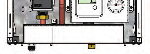
39 6.3 Use of the commissioning switch The commissioning switch is located inside the case of the ModuSat next to the manometer and heat meter display. This switch enables the unit to be put into a manual heating on mode prior to full unit commissioning to enable the testing of the secondary / apartment heating circuit. Please note that this function should not be used until the secondary installation is complete i.e. flushed, treated and refilled to the correct pressures. Commissioning Switch Pump Manual Override Rocker Switch To enable the heating run mode setting the button should be depressed and held in for approximately 30 seconds. The heating PICV opens and the pump starts its self venting procedure (As described in section 6.5). The unit will then run at a pre-set output temperature of 45 C thus providing a safe temperature for UFH circuits and also a gentle warm up of radiator circuits. This function will run for a pre-set period of approx. 45minutes. If the heating needs to be run again, the process is repeated and then the cycle will start and run for a further 45 mins. Please note: The rocker switch above the commissioning push button is the Pump Manual Override. This should NOT be operated or used by persons other than Evinox Engineers as it is for emergency use only. 39


40 6.4 Adjustment of TMV The ModuSat unit is fitted with an internal blending valve on the DHW outlet from the integral storage tank. This enables the DHW storage temperature to be higher to improve DHW recovery and draw off rates but also ensure that the DHW to outlets does not exceed the design / safe temperatures as an additional fail safe protection. The nominal parameters for the valve are as follows: Cold supply water temperature 15⁰C +/- 2⁰C Hot supply water temperature 75⁰C +/- 2⁰C Nominal cold water pressure 3 Bar +/- 0.2 Bar Nominal hot water pressure 3 Bar +/- 0.2 Bar Blended flow rate 18 +/- 4 The water outlet set temperature is achieved within 15 seconds and the mixed water temp is approximately 55⁰C +/-2 C. The default valve setting is 55⁰C if this needs adjustment this can be done by loosening the top screw and turning the dial to the required setting. It should be noted that as both pressure and flow rates influence the mixed water temperature it is most important that these are checked and verified during installation / initial checks. Please also note that there are tolerances within the temperature and flow settings as detailed within the tables above. Technical Characteristics Working Range: C Max working temperature: 90 C Accuracy: ±2 C Max static pressure(structural pressure): 10 bar Max working pressure: 5 bar Min 1 36 C 2 40 C 3 44 C 4 50 C 5 55 C Max Please refer to the hydraulic layouts on pages 5-7 with details of the blending valve orientation. 40
41 6.5 Pump Start-up - Wilo PWM Pump The Wilo Pulse-width modulation (PWM) pump features dry running protection to eliminate burn out and provides compliance with the 2015 pump efficiency regulations. Description of the pump The pump consists of a hydraulic system, a glandless pump motor with a permanent magnet rotor, and an electronic control module with an integrated frequency converter. The control module provides speed control by a PWM signal from the ModuSat control board and indicator LED to display the pump operating status switch automatically to a pre-set speed. During automatic venting function, after the initial first start-up of the unit, the Pump runs alternately with high and low speeds to help remove any air from the pump. The pump should be left to carry out this process and once complete the pump will Filling and venting The venting function lasts 10 minutes and is indicated with quick green LED blinking. Noises may be heard while the venting function is running. After 10 minutes, the pump stops and goes automatically in to the pre-set function. Please note: When the unit is switched over to heating mode please note that the pump will run for 2 mins prior to the heating PICV opening, this is not a fault in the unit but a normal control function as the HIU asses the current heating circuit flow temperature. 41
42 Pump LED Description of Status LED Indicators Diagnosis Status Remedy Lights green Pump in operation Pump runs Normal operation according its setting Blinks quick PWM model: Pump in standby / Normal operation green Venting procedure Blinks red/ green Pump in function but stopped Blinks red Pump out of function Pump restarts by itself after the fault is disappeared Pump stopped (blocked) 1. Low voltage U<160 V or High voltage U>253 V 2. Module overheating: temperature inside motor too high Pump does not restart by itself due to a permanent failure 1. Check voltage supply 195 V < U < 253 V 2. Check water and ambient temperature Change pump LED off No power No power to pump 1. Pump is not connected to power supply 1. Check cable connection 2. LED is damaged 2. Check if pump is running 3. Electronics are damaged Change pump 6.6 Warranty The warranty has value if good practice has been strictly observed for installation and use. Evinox is not liable for equipment breakdown and damage to persons and objects caused by: Transportation Installation in which the Standards in force and good practice were not complied with Improper use of the device, abnormal use conditions, tampering by unauthorised personnel or inadequate maintenance; therefore by: Corrosion and/or sludge accumulation; lack of electrical energy; absence of suitable drainage; exceeding operating pressures; electrical and water system faults Freezing or fortuitous causes Wear due to normal use Malfunctioning of control and safety parts Corrosion due to oxygenation or roaming currents From commissioning, ModuSat TP appliances are guaranteed against all manufacturing faults and material defects for a period of: 5 years for the stainless steel heat exchangers 2 years for parts and labour * (Where Evinox do not carry out the commissioning or have a developer agreement in place the two year warranty will cover parts with no labour cover) However, the ModuSat TP warranty will always start from the date of the serial number and will be extended by a maximum of 6 months to allow for project completion. If the ModuSat TP is commissioned before the 6 month extensions the warranty will start from the commissioning date. 42
43 This guarantee is strictly limited to the supply, free of charge, of parts acknowledged as being defective after inspection by our technical departments, with the exclusion of labour and transport costs arising from this. These parts once again become the property of Evinox and must be returned to them without delay. Failure to comply with the relevant installation requirements of the Building Regulations, Local Water Byelaws and Building Standards will invalidate any warranty claim. The ModuSat TP must be fitted with our isolation valve kit for servicing and warranty work. Warranty calls that include draining the system will be chargeable if isolation valves have not been fitted. It is imperative that the level of corrosion protector within the system is kept within industry guidelines at all times. Special attention should be given to ensure that, after any decoration or building works where radiators might be removed, the system is replenished with chemicals. Non-use of inhibitor will invalidate the warranty. We will register the warranty when we commission the boiler and ModuSat TP units. Any warranty claims that are a result of user error, poor installation or lack of servicing will be chargeable. Please note that all replacement parts provided under warranty are subject to factory inspection to determine cause of failure. Replacement parts are chargeable until passed as faulty by Evinox, when a credit will be provided. Any parts that have failed as a result of poor servicing or misuse will not be covered by our warranty. Any modifications to the appliance will invalidate the warranty. Installation of the Evinox unit should only be carried out by suitably qualified personnel and have relevant approval for associated plumbing and electrical works. If failure occurs due to poor or faulty installation work carried out by non qualified personnel, this will invalidate the warranty. Your Evinox appliance is one of the most reliable and technically advanced products available. However, it is imperative that it is installed correctly, commissioned and serviced in accordance with Evinox installation and servicing manuals to ensure long life, reliability and fuel savings. Exclusion of the Guarantee The following are not covered by the guarantee: a) Electric indicators Electric degradation of parts resulting from connection and installation on electricity supply whose voltage measured at the entry of the apparatus would be lower by 15 % or higher of 10 % than the nominal voltage of 230 volts Degradation of parts coming from external elements with apparatus (effect of storm, moisture, freezing, etc) Seals Automatic air vents All consecutive incidents resulting from a lack to check the safety components (unvented kit etc) Scaling, nor its consequences Corrosions due to chloride concentrations in domestic hot water higher than 60 mg/l The wear of the safety relief valve b) Postage costs of the parts, labour and displacement 43
44 Note: in a constant preoccupation with an improvement of our materials, any modification considered to be useful by our engineering departments and commercial can intervene without notice. * See full terms and conditions of warranty 44
1372 722277 E. technical@evinox.co.uk W. www.evinox.co.uk 2551390A")
45 Evinox reserves the right to make changes and improvements which may necessitate alteration to the specification without prior notice. Evinox Ltd T. +44 (0) E. W A
Installation, Operation and Maintenance Instructions for Electronically Controlled Pressurisation Units
 Installation, Operation and Maintenance Instructions for Electronically Controlled Pressurisation Units Models: EPS Single Pump EPT Twin Pump EPS-HP EPT-HP Single Pump High Pressure Twin Pump High Pressure
ECONORESS ELECTRONIC EPS & EPT - ENHANCED PRESSURISATION SET INSTALLATION OPERATION & MAINTENANCE DOCUMENTATION
 ECONORESS ELECTRONIC EPS & EPT - ENHANCED PRESSURISATION SET INSTALLATION OPERATION & MAINTENANCE DOCUMENTATION OCT2010 STOKVIS ENERGY SYSTEMS 96R WALTON ROAD EAST MOLESEY SURREY KT8 0DL TEL: 020 87833050
System Pressure Manager Standard & System Pressure Manager Plus
 System Pressure Manager Standard & System Pressure Manager Plus Installation, Commissioning & Servicing Instructions Note: THESE INSTRUCTIONS MUST BE READ AND UNDERSTOOD BEFORE INSTALLING, COMMISSIONING,
Installation, Operation and Maintenance Instructions for Electronically Controlled Pressurisation Units Digital Range
 Installation, Operation and Maintenance Instructions for Electronically Controlled Pressurisation Units Digital Range Models: DS 126 Single Pump / Single System DT 126 Twin Pump / Single System DS 160
Twin & Triple Control Concealed Thermostatic Shower Valve
 Twin & Triple Control Concealed Thermostatic Shower Valve Installation & Operating Guide Please leave this installation & user guide with the end user CONTENTS: 1. Introduction & Safety 1 2. Dimensions
VERTICAL AIR COMPRESSORS
 VERTICAL AIR COMPRESSORS MODEL NO: VE11C150, VE15C150, VE18C150 PART NO: 2226005, 2226000, 2226015 OPERATION & MAINTENANCE INSTRUCTIONS LS0615 INTRODUCTION Thank you for purchasing this CLARKE Vertical
VERTICAL AIR COMPRESSORS
 VERTICAL AIR COMPRESSORS MODEL NO: VE15C150, VE18C150, VE25C150 PART NO: 2226010, 2226020, 2226025 OPERATION & MAINTENANCE INSTRUCTIONS LS0715 INTRODUCTION Thank you for purchasing this CLARKE Vertical
Spirax Compact FREME Flash Recovery Energy Management Equipment
 IM-UK-cFREME UK Issue 1 Spirax Compact FREME Flash Recovery Energy Management Equipment Installation and Maintenance Instructions 1. Safety information 2. General product information 3. Installation 4.
Renewables. Tribune HE Unvented Hot Water Cylinders Installation and Maintenance Instructions. Issue 17 July 2012
 Renewables Tribune HE Unvented Hot Water Cylinders Installation and Maintenance Instructions Issue 17 July 2012 IMPORTANT NOTE TO THE INSTALLER Read these instructions before commencing installation. Unvented
PRAHER PLC-MP AQUASTAR MANAUL 2009
 PRAHER PLC-MP AQUASTAR MANAUL 2009 1. Copyrights This Operating Manual contains copyright-protected information. All rights reserved to Praher Kunststofftechnik GmbH. This Operating Manual is designed
PLEASE READ CAREFULLY BEFORE INSTALLING OR USING MEGA POOL SAVER MPS 1100
 MPS-1100 User Manual Mega Pool Saver Ltd PLEASE READ CAREFULLY BEFORE INSTALLING OR USING MEGA POOL SAVER MPS 1100 For further up to date instructions on how to install Mega Pool Saver MPS 1100, please
Self-help Temperature Adjustment
 Self-help Temperature Adjustment The Shower Valve temperature is pre-set to 42 C, but on certain installations the temperature may need to be adjusted. Note: The hot water supply must be above 60 C. Turn
Measurement accessories METPOINT OCV for the measurement in systems up to 40 bar
 EN - english Instructions for installation and operation Measurement accessories METPOINT OCV for the measurement in systems up to 40 bar Dear customer, Thank you for deciding in favour of the METPOINT
Installation, Operation and Maintenance Instructions for Electronically Controlled Pressurisation Units
 Installation, Operation and Maintenance Instructions for Electronically Controlled Pressurisation Units Micro-S / Micro-S Digital Wall Hung Unit Please fulfil all listed requirements prior to and during
AUTOMATIC GAS MANIFOLDS
 AUTOMATIC GAS MANIFOLDS Phoenix Pipeline Products Limited. Unit 8, McKenzie Industrial Park, Tel No.: 44 (0) 161 428 7200 Bird Hall Lane, Fax No.: 44 (0) 161 428 7010 Stockport, Email: info@p3-phoenix.com
CAST IRON SAFETY VALVE TYPE 6301
 CHARACTERISTICS The 6301 safety valve is dedicated to protect the equipment from potential overpressure. This is an automatic device that closes when the pressure conditions are back to normal. It is a
SMV-001 Thermostatic Shower Mixer Valve Installation Instructions & Adjustment Settings
 SMV-001 Thermostatic Shower Mixer Valve Installation Instructions & Adjustment Settings 38 READ ALL INSTRUCTIONS CAREFULLY BEFORE INSTALLATION. LEAVE THIS BOOKLET WITH THE END USER FOR FUTURE REFERENCE
MAGNA-CHEM AUTOMATIC CHLORINATOR - MODEL: CSA-2P MAGNA ORP Chlorine Pump
 A. PARTS MAGNA-CHEM AUTOMATIC CHLORINATOR - MODEL: CSA-2P MAGNA ORP Chlorine Pump Assembly & Operating Instructions Parts for liquid chlorine pump head 1pc. 1/4 poly delivery tubing, 4 meters 1pc. drum
M03 WUNDATRADE. Heat Pump Manifold. Before you start: Check the contents. Optional. ...a division of WUNDA GROUP PLC
 Before you start: Check the manifold box contents against the list below. Check the contents Flow gauges 1. Bar assembly with manual return valves 2. 2 x Auto air vent & drain hose attachments Optional
Installation, Operating, Maintenance and Safety Instructions for. Pressurised water systems for boats
 FLOMAX-SYSTEM DOC532/11 Installation, Operating, Maintenance and Safety Instructions for FLOMAX-SYSTEM Pressurised water systems for boats CW343A FloMax System 12 volt d.c. CW344A FloMax System 24 volt
24L OIL FREE AIR COMPRESSOR MODEL NO: TIGER 7/250 PART NO: OPERATION & MAINTENANCE INSTRUCTIONS LS10/13
 24L OIL FREE AIR COMPRESSOR MODEL NO: TIGER 7/250 PART NO: 2244030 OPERATION & MAINTENANCE INSTRUCTIONS LS10/13 INTRODUCTION Thank you for purchasing this product. Before attempting to use this product,
Installation, operating and maintenance Instructions for Seemag bypass level indicator
 Issue: S Date: 05-09-14 Type G35 General information The Seetru bypass magnetic level indicator, abbreviate SEEMAG, serves to show the filling level of fluids in tanks, basins, tubes etc. The Seemag operates
MODEL NUMBER: M20005 AIR SOURCE KIT. 30% Duty Compressor on. 2.0 Gallon Air Tank SAVE THIS MANUAL FOR FUTURE REFERENCE
 MODEL NUMBER: M20005 AIR SOURCE KIT 30% Duty Compressor on 2.0 Gallon Air Tank SAVE THIS MANUAL FOR FUTURE REFERENCE USER MANUAL IMPORTANT SAFETY INSTRUCTIONS CAUTION - To reduce risk of electrical shock
Deluge Optimo Shower valve and kit 10032CP
 Deluge Optimo Shower valve and kit 10032CP Installation, Operation and Maintenance Please leave these instructions with the user Intatec Limited Airfield Industrial Estate, Hixon, Staffordshire, ST18 0PF
Scald Protection Three-Way Thermostatic Mixing Valve
 CALEFFI www.caleffi.com 383.04 Scald Protection Three-Way Thermostatic Mixing Valve Copyright 00 Caleffi 3 Series Installation, commissioning and servicing instructions Function Scald Protection Three-Way
Installation Guide - C01202 & C01203 Thermostatic Mixing Valve TMV2
 The following information is required for use when the Saracen range of thermostatic mixing valves is used in a TMV2 Applications under the requirements of BS EN 1111: 1999 Sanitary tap ware Thermostatic
MODEL NUMBER: PSI AIR SOURCE KIT 200 PSI Compressor on 2.0 Gallon 200 PSI Air Tank
 IMPORTANT SAFETY INSTRUCTIONS CAUTION - To reduce risk of electrical shock or Electrocution: MODEL NUMBER: 20008 200 PSI AIR SOURCE KIT 200 PSI Compressor on 2.0 Gallon 200 PSI Air Tank IMPORTANT: It is
200 PSI FAST-FILL AIR SOURCE KIT
 200 PSI FAST-FILL AIR SOURCE KIT 55% Duty Compressor on 2.0 Gallon Air Tank PART NO. 20007 IMPORTANT: It is essential that you and any other operator of this product read and understand the contents of
200 PSI HIGH-FLOW AIR SOURCE KIT
 200 PSI HIGH-FLOW AIR SOURCE KIT 50% Duty Compressor on 2.0 Gallon Air Tank PART NO. 20008 IMPORTANT: It is essential that you and any other operator of this product read and understand the contents of
New AQF Filter Polymer Filtration System
 New AQF Filter Polymer Filtration System Operator Manual Covering Serial Number 20002001 onwards February 2011 Index Disclaimer notice...3 Introduction...4 Important safety notices...5 Getting started...6
Electronic Single and Twin Pump System Pressure Managers
 Electronic Single and Twin Pump System Pressure Managers Installation, Commissioning & Servicing Instructions Note: THESE INSTRUCTIONS MUST BE READ AND UNDERSTOOD BEFORE INSTALLING, COMMISSIONING, OPERATING
ENERGY BLADE 3K4. Energy Blade Installation Instructions
 ENERGY BLADE 3K4 Energy Blade Installation Instructions 1 Contents General information 2 Scope of these instructions 2 Product information 2 Designated use 3 Warranty 3 Safety instructions 4 Assembly and
Dual Solenoid Gas Valve Installation
 Installation IMPORTANT: These instructions are intended as a guide for qualified personnel installing or servicing FLYNN Gas Products. Carefully follow all instructions in this bulletin and all instructions
Instruction Manual Contact Pressure Vacuum Gauge
 MS10 Instruction Manual Contact Pressure Vacuum Gauge Table of Contents 1. Safety Instructions 2. Intended Applications 3. Product Description and Functions 4. Installation 5. Commissioning 6. Maintenance
Latvin Luxury Shower Panel. Telephone Product Specification. ~ Minimum Working Pressure 1.0 bar ~ Maximum Working Pressure 3.
 Product Specification ~ Minimum Working Pressure 1.0 bar ~ Maximum Working Pressure 3.0 bar Latvin Luxury Shower Panel ~ Fixing Centres 150mm +/- 10mm ~ Outlet size 1/2" Bottom Outlet Always maintain a
Budget Range Operators Handbook
 Budget Range Operators Handbook BAMBI AIR COMPRESSORS LTD 152 Thimble Mill Lane Heartlands Birmingham B7 5HT United Kingdom Tel: 0121 322 2299 Fax: 0121 322 2297 Email: sales@bambi-air.co.uk www.bambi-air.co.uk
PROPORTIONING VALVE. Model 150 INSTRUCTION MANUAL. March 2017 IMS Company Stafford Road
 PROPORTIONING VALVE Model 150 INSTRUCTION MANUAL March 2017 IMS Company 10373 Stafford Road Telephone: (440) 543-1615 Fax: (440) 543-1069 Email: sales@imscompany.com 1 Introduction IMS Company reserves
The Univentor 1250 Anaesthesia Unit
 THE UNIVENTOR 1200/1250 ANAESTHESIA UNIT The Univentor 1250 Anaesthesia Unit TABLE OF CONTENTS EDITION 1 Section 1 - WARRANTY & SERVICE 1.1. WARRANTY 2 1.2. DAMAGED SHIPMENTS 2 1.3. SERVICE 2 Section 2
UsER manual for Watersens ph -REDOX
 UsER manual for Watersens -REDOX Cl 8 1 2 6 3 3 7 7 4 4 4 4 Parts List 1 Redox Probe 1 x 2 PH Probe 1 x 5 Tube Weight 2 x 6 Connection Valve 1 x chlorine 3 Chlorine and Pumps 2 x 7 Dosing Valve 2 x 5 5
Manual Actuated Boiler Blowdown Valves
 Manual Actuated Boiler Blowdown Valves Installation and Maintenance Instructions 1. Safety information 2. General product information 3. Installation 4. Operation 5. Maintenance 6. Spare parts p.1 1. Safety
36E DSI, HSI & Proven Pilot Two-Stage Combination Gas Valve INSTALLATION INSTRUCTIONS
 INLET PRESS TAP WTE-RODGERS 36E96-314 DSI, HSI & Proven Pilot Two-Stage Combination Gas Valve INSTALLATION INSTRUCTIONS Operator: Save these instructions for future use! FAILURE TO READ AND FOLLOW ALL
Propane Conversion Kit Instructions
 604 8 0/ US/CA For heating engineers Propane Conversion Kit Instructions Logano G4 X gas-fired boiler This conversion kit and the accompanying instructions are for conversion of G4 X gas-fired boilers
BGA158 Series CE Approved Class A Shutoff Gas Valve
 Installation Instructions BGA158 Issue Date August 24, 2011 BGA158 Series CE Approved Class A Shutoff Gas Valve Applications The BGA158 Series shutoff gas valve is an electrically operated gas valve that
Model PSI Compressor with 3-Gallon Air Tank 12VDC
 Model 6350 150 PSI Compressor with 3-Gallon Air Tank 12VDC IMPORTANT: It is essential that you and any other operator of this product read and understandd the contents of this manual before installing
100C Air Compressor Kit
 10010 100C Air Compressor (standard mounting bracket, CE Spec) 10014 100C Air Compressor (no leader hose or check valve, CE Spec) 10016 100C Air Compressor (with Omega Bracket, CE Spec) IMPORTANT: It is
TECHNICAL DATA MAINTENANCE AIR COMPRESSOR MODEL G-1
 Dry 131h 1. DESCRIPTION The Viking Model G-1 Maintenance Air Compressor is an electric motor-driven, aircooled, single-stage, oil-less compressor. The unit is equipped with a check valve and provides a
NIV EAU MATIC ST User Manual Made in Canada
 NIV EAU MATIC ST User Manual Made in Canada www.niveaumatic.com info@niveaumatic.com -2- Table of contents Introduction Section 1 Page 4 Installation Section 2 Pages 5 to 10 2.1 Control box 2.2 Sensor
Intamix Thermostatic Mixing Valve
 Intamix Thermostatic Mixing Valve TMV2 & TMV3 Installation Guide Intatec Ltd Airfield Industrial Estate Hixon Staffordshire ST18 0PF In this procedure document we have endeavoured to make the information
444C DUAL PERFORMANCE VALUE PACK
 (Chrome) PART NO. 44432 IMPORTANT: It is essential that you and any other operator of this product read and understand the contents of this manual before installing and using this product. SAVE THIS MANUAL
OWNER S GUIDE DUAL CONTROL THERMOSTATIC SHOWER VALVE. Shower Control. may differ depending on choice of Model. Concealing Plate. Handles and ISSUE 01
 DUAL CONTROL THERMOSTATIC SHOWER VALVE Shower Control Handles and Concealing Plate may differ depending on choice of Model OWNER S GUIDE ISSUE 01 These instructions cover all exposed or concealed versions
24L AIR COMPRESSOR OPERATION & MAINTENANCE INSTRUCTIONS MODEL NO: RANGER 7/240 PART NO: LS0913
 24L AIR COMPRESSOR MODEL NO: RANGER 7/240 PART NO: 2242000 OPERATION & MAINTENANCE INSTRUCTIONS LS0913 INTRODUCTION Thank you for purchasing this CLARKE 24L Air Compressor. Please read this manual fully
Installation Instructions / Operating & Maintenance Manual Midi-Fill Digital Pressurisation Unit Models MFD15 & MFD22
 Arrow Valves Ltd Installation Instructions / Operating & Maintenance Manual Midi-Fill Digital Pressurisation Unit Models MFD15 & MFD22 Tel 01442 823 123 Fax 01442 823 234 www.arrowvalves.co.uk Model shown
SPIROVENT VACUUM DEGASSERS
 SPIROVENT VACUUM DEGASSERS S P I R O V E N T A I R S U P E R I O R FLUID AND GAS There are always a certain amount of gasses in a fluid, dependent on pressure and temperature. The British physicist William
200 PSI COMPRESSORS - MODEL NUMBERS
 200 PSI COMPRESSORS - MODEL NUMBERS 380C AIR COMPRESSOR KIT PART NO. 38033 480C AIR COMPRESSOR KIT PART NO. 48043 380C 480C IMPORTANT: It is essential that you and any other operator of this product read
BGA158 Series CE Approved Class B Shutoff Gas Valve
 Installation Instructions BGA158 Issue Date March 22, 2016 BGA158 Series CE Approved Class B Shutoff Gas Valve Applications The BGA158 Series shutoff gas valve is an electrically operated shutoff valve
IMPORTANT SAFETY INSTRUCTIONS
 IMPORTANT SAFETY INSTRUCTIONS CAUTION - To reduce risk of electrical shock: - Do not disassemble. Do not attempt repairs or modifications. Refer to qualified service agencies for all service and repairs.
OWNER S MANUAL NMB SERIES
 OWNER S MANUAL NMB SERIES NMB Manual V2.0.doc 1. PARTS IDENTIFICATION LIST 1. 5. 2. 4. 3. 6(a). 6(b). Figure 1.1 1. Powerpack with timer option (x1) 2. Cell (x1) 3. Cell Housing (x1) 4. O-ring (x1) 5.
36E DSI and HSI Two-Stage Combination Gas Valve INSTALLATION INSTRUCTIONS
 INLET PRESS TAP WTE-RODGERS 36E54-214 DSI and HSI Two-Stage Combination Gas Valve INSTALLATION INSTRUCTIONS Operator: Save these instructions for future use! FAILURE TO READ AND FOLLOW ALL INSTRUCTIONS
Installation, Operation & Maintenance Instructions
 Installation, Operation & Maintenance Instructions Please leave this instruction booklet with the home owner as it contains important guarantee, maintenance and safety information Read this manual carefully
WATER HEATER THERMAL EXPANSION TANKS Owner s Manual. Safety Instructions Installation Maintenance Warranty. Models: 2-5 Gallon Capacity
 WATER HEATER THERMAL EXPANSION TANKS Owner s Manual Safety Instructions Installation Maintenance Warranty Models: 2-5 Gallon Capacity Thank You for purchasing this Thermal Expansion Tank. Properly installed
100L AIR COMPRESSOR MODEL NO: TIGER 16/1010 PART NO: OPERATION & MAINTENANCE INSTRUCTIONS LS01/13
 100L AIR COMPRESSOR MODEL NO: TIGER 16/1010 PART NO: 2244025 OPERATION & MAINTENANCE INSTRUCTIONS LS01/13 INTRODUCTION Thank you for purchasing this product. Before attempting to use this product, please
DPC-30 DPC-100. Reference Manual
 DPC-30 DPC-100 Reference Manual 1. Introduction 1.1 Description The Martel DPC Digital Pneumatic Calibrator improves upon traditional dial gauge pneumatic calibrators. The Martel DPC improves accuracy,
AutoChanger Installation & User Guide Issue 2
 1 INDEX Page 1. Introduction... 3 2. AutoChanger Components Guide 4 3. Installation. 5-11 a) Installation Guidelines.. 5 b) Installation Retrofit... 6-11 c) Installation New... 11 4. AutoChanger User Guide
Installation Instructions and User Guide 15mm & 22mm Thermostatic Mixing Valve
 Installation Instructions and User Guide 15mm & 22mm Thermostatic Mixing Valve TMV3 / TMV2 Combined Valve C85079 C85081 C85080 C85082 It is important that these guidance notes are read and fully understood
WORCESTER GREENSTORE. Indirect Unvented Cylinder with Solar Coil FOR USE WITH WORCESTER GREENSTORE SYSTEM HEATPUMP ONLY GB/IE
 WORCESTER GREENSTORE Indirect Unvented Cylinder with Solar Coil FOR USE WITH WORCESTER GREENSTORE SYSTEM HEATPUMP ONLY GB/IE WORCESTER GREENSTORE 180 CYLINDER SOLAR COMPATIBLE WORCESTER GREENSTORE 280
CP10 Sensor Installation and Maintenance Instructions
 4030150/9 IM-P403-26 EMM Issue 9 CP10 Sensor Installation and Maintenance Instructions 1. Safety information 2. General product information 3. Installation 4. Maintenance 5. Spare parts Copyright 2017
Pressure Independent Control Series
 Document No. 155-522 Pressure Independent Control Series Two-Way Cast Iron Flanged Bodies, ANSI 125 and 250 Description Siemens Pressure Independent Control Valves integrate three functions into a single
97C COMPRESSOR KIT 12V PART NO C COMPRESSOR KIT 24V PART NO C COMPRESSOR KIT PART NO
 97C COMPRESSOR KIT 12V PART NO. 00097 97C COMPRESSOR KIT 24V PART NO. 02497 98C COMPRESSOR KIT PART NO. 00098 97C 98C IMPORTANT: It is essential that you and any other operator of this product read and
Installation Operation Maintenance. Bermad Level Control Valve with Modulating Horizontal Float Pilot valve One Way Flow IOM.
 Bermad Level Control Valve with Modulating Horizontal Float Pilot valve One Way Flow Model: FP 450-80 Installation Operation Maintenance PAGE 1 OF 5 1. Safety First BERMAD believes that the safety of personnel
420C AIR COMPRESSOR KIT PART NO C AIR COMPRESSOR KIT PART NO
 420C AIR COMPRESSOR KIT PART NO. 42042 460C AIR COMPRESSOR KIT PART NO. 46043 420C 460C IMPORTANT: It is essential that you and any other operator of this product read and understand the contents of this
ADVANCE STAINLESS STEEL UNVENTED HOT WATER SYSTEMS
 ISSUE JAN. 009 INSTALLATION AND USER GUIDE ADVANCE STAINLESS STEEL UNVENTED HOT WATER SYSTEMS ADVANCE APPLIANCES LTD PLEASE RETAIN AND ENSURE SERVICE RECORDS ARE KEPT UP TO DATE. STAINLESS STEEL UNVENTED
TABLE OF CONTENTS TECHNICAL DOCUMENTATION 03
 INSPIRED EF F ICIENCY PRESSURISATION UNITS MAXI P R ESSUR I SAT I O N U NI T S T E CH N I CAL D O CUMEN T A T I O N I SSUE 1 0 /1 7 R e v. 0 1 TABLE OF CONTENTS 1. 2. 3. 4. 5. 6. 7. 8. 9. Technical Data
RAM 4021 Operation Manual
 RAM 4021 Operation Manual Worldwide Manufacturer of Gas Detection Solutions TABLE OF CONTENTS RAM 4021 For your safety...3 Description...3 Set-up mode...4 Annunciator lights/alarms...4 Operation...5 Calibration...6
TECHNICAL DATA. TRIMPAC Model B-5 & B-5B
 September 16, 2013 Trimpac 250a 1. DESCRIPTION DEsCRIPTIoN is a factory assembled trim package for a ed an electric/pneumatic release module in a metal enclosure. The standard trim normally required on
553 Series.
 38467.03 www.caleffi.com Pre-adjustable filling units Copyright 01 Caleffi 3 Series Function The automatic filling valve is a device consisting of a pressure reducing valve with compensating seat, visual
Operator: Save these instructions for future use!
 INLET PRESS TAP WHITE-RODGERS 36E93-304 Delay-Opening Combination Gas Valve INSTALLATION INSTRUCTIONS Operator: Save these instructions for future use! FAILURE TO READ AND FOLLOW ALL INSTRUCTIONS CAREFULLY
RAM 4021-PR. Operation Manual. Worldwide Manufacturer of Gas Detection Solutions
 RAM 4021-PR Operation Manual Worldwide Manufacturer of Gas Detection Solutions TABLE OF CONTENTS RAM 4021-PR For Your Safety... 2 Description.... 2 Setup Mode.... 2 Lights/Alarms.... 3 Operation.... 4
Catalina Spa-kle Installation and User Guide
 Catalina Spa-kle Installation and User Guide Computer controlled automatic bromine generator for spas, hot tubs and swimspas. 1 TABLE OF CONTENTS 1. Safety Instructions and Installer Precautions 2. Installation
42045 Heavy Duty ADA Base Model Kit: 85/105 PSI (ADA Compressor Only) Heavy Duty ADA Base Model Kit: 110/145 PSI (ADA Compressor Only)
 Heavy Duty ADA Base Model Kit: 110/145 PSI (ADA Compressor Only)") 42045 Heavy Duty ADA Base Model Kit: 85/105 PSI (ADA Compressor Only) 42047 Heavy Duty ADA Base Model Kit: 110/145 PSI (ADA Compressor Only) 45052 Constant Duty ADA Base Model Kit: 85/105 PSI (ADA Compressor
42045 Heavy Duty ADA Base Model Kit: 85/105 PSI (ADA Compressor Only) 42047 Heavy Duty ADA Base Model Kit: 110/145 PSI (ADA Compressor Only) 45052 Constant Duty ADA Base Model Kit: 85/105 PSI (ADA Compressor
Installation, Operating, Maintenance and Safety Instructions for MAXI-SYSTEM Pressurised water systems for boats
 MAXI-SYSTEM DOC50/ Installation, Operating, Maintenance and Safety Instructions for MAXI-SYSTEM Pressurised water systems for boats CW CW Maxi-System.9+ volt d.c. Maxi-System.9+ volt d.c. CW99A Maxi-System
24L AIR COMPRESSOR MODEL NO: TIGER 11/250 PART NO: OPERATION & MAINTENANCE INSTRUCTIONS LS01/13
 24L AIR COMPRESSOR MODEL NO: TIGER 11/250 PART NO: 2244010 OPERATION & MAINTENANCE INSTRUCTIONS LS01/13 INTRODUCTION Thank you for purchasing this product. Before attempting to use this product, please
AIR COMPRESSOR OPERATION & MAINTENANCE INSTRUCTIONS MODEL NO: CHAMP 3 PART NO: LS0115
 AIR COMPRESSOR MODEL NO: CHAMP 3 PART NO: 2225222 OPERATION & MAINTENANCE INSTRUCTIONS LS0115 INTRODUCTION Thank you for purchasing this CLARKE Air Compressor. Please read this manual fully before use
Flamco Flamco-Fill STA Flamco-Fill STM
 STA STM Typ STA 5936 Typ STM 5937 GB Installation and operating instructions 1999, 2 Contents GB UK Limited P.O. Box 9, Washway Lane, St. Helens, Merseyside WA10 6FE United Kingdom Telephone: 01744 744744
OC Panel High Limit Aquastat Kit, Manual Reset p/n
 OC Panel High Limit Aquastat Kit, Manual Reset p/n 233202 Instruction Sheet APPLICATION The OC (Option Control) Panel High Limit Aquastat Kit provides electronic temperature sensing in a UL limit-rated
RAM 4021-DPX Operation Manual
 RAM 4021-DPX Operation Manual Worldwide Manufacturer of Gas Detection Solutions TABLE OF CONTENTS ABL 4021-DPX / RAM 4021-DPX For Your Safety... 3 Description... 3 Setup Mode... 4 Lights/Alarms... 4 Operation...
250C-IG COMPRESSOR KIT 12V PART NO C-IG COMPRESSOR KIT 24V PART NO
 250C-IG COMPRESSOR KIT 12V PART NO. 25050 250C-IG COMPRESSOR KIT 24V PART NO. 25058 IMPORTANT: It is essential that you and any other operator of this product read and understand the contents of this manual
Pressure Independent Control Valve (PICV) Fig DN15-32
 Fig DN15-32") Installation and Operating Instructions Pressure Independent Control Valve (PICV) Fig. 1932 - DN15-32 GENERAL NOTES The Hattersley Fig.1932 PICV; can be used in variable volume heating and chilled water
Installation and Operating Instructions Pressure Independent Control Valve (PICV) Fig. 1932 - DN15-32 GENERAL NOTES The Hattersley Fig.1932 PICV; can be used in variable volume heating and chilled water
PRESSURE INDEPENDENT CONTROL VALVE (PICV)
") INSTALLATION, OPERATING AND MAINTENANCE INSTRUCTIONS PRESSURE INDEPENDENT CONTROL VALVE (PICV) D991 GENERAL NOTES OF SAFETY The Crane D991 PICV; can be used in variable volume heating and chilled water
INSTALLATION, OPERATING AND MAINTENANCE INSTRUCTIONS PRESSURE INDEPENDENT CONTROL VALVE (PICV) D991 GENERAL NOTES OF SAFETY The Crane D991 PICV; can be used in variable volume heating and chilled water
Scald Protection 3-Way Thermostatic Mixing Valve
 383.06 www.caleffi.com Scald Protection 3-Way Thermostatic Mixing Valve Copyright 06 Caleffi 3 Series Installation, commissioning and servicing instructions Function Scald Protection Three-Way Thermostatic
200L BELT DRIVEN AIR COMPRESSOR
 200L BELT DRIVEN AIR COMPRESSOR MODEL NO: BOXER 14/200 PART NO: 2245215 OPERATION & MAINTENANCE INSTRUCTIONS ORIGINAL INSTRUCTIONS LS0118 ISS 4 INTRODUCTION Thank you for purchasing this CLARKE 200L Belt
120 PSI FAST-FILL AIR SOURCE KIT 25% Duty Compressor on 1.5 Gallon Air Tank
 120 PSI FAST-FILL AIR SOURCE KIT 25% Duty Compressor on 1.5 Gallon Air Tank PART NO. 20003 IMPORTANT: It is essential that you and any other operator of this product read and understand the contents of
MANUAL. Sesame. Thermoplastic Tank Technologies
 MANUAL Sesame Thermoplastic Tank Technologies INSTALLATION AND USER GUIDE CONTENT 1. GENERAL 3 2. IMPORTANT 3 3. INSTALLATION EXPANSION VESSEL 4 4. USE EXPANSION VESSEL 5 5. AIR CELL REPLACEMENT 5 5.1
In Vessel Composter Installation & Commissioning Manual
 In Vessel Composter Installation & Commissioning Manual Contents Customer responsibilities Transportation Lifting Delivery Pre-installation requirements Installation Drainage Ventilation Levelling Unpacking
400C & 450C DUAL PERFORMANCE VALUE PACKS
 (Chrome) PART NO. 40013 (Silver) PART NO. 45012 (Chrome) PART NO. 45013 IMPORTANT: It is essential that you and any other operator of this product read and understand the contents of this manual before
AIR COMPRESSOR OPERATING INSTRUCTION AND PARTS LIST
 AIR COMPRESSOR OPERATING INSTRUCTION AND PARTS LIST OIL-LESS TYPE IMPORTANT: PLEASE READ CAREFULLY BEFORE STARTING OPERATIONS. THE CONTENTS ARE FOR GENERAL INFORMATION OF ALL THE SIMILAR MODELS. Record
450P AUTOMATIC PORTABLE COMPRESSOR EXTREME SERIES
 EXTREME SERIES PART NO. 45043 IMPORTANT: It is essential that you and any other operator of this product read and understand the contents of this manual before installing and using this product. SAVE THIS
36H SERIES Combination Gas Valve
 FAILURE TO READ AND FOLLOW ALL INSTRUCTIONS CAREFULLY BEFORE INSTALLING OR OPERATING THIS CONTROL COULD CAUSE PERSONAL INJURY AND/OR PROPERTY DAMAGE. DESCRIPTION The 36H series combination gas valve is
Commercial Softeners. Installation, Operation & Maintenance Guide. Manual 002.1
 Commercial Softeners Installation, Operation & Maintenance Guide Manual 002.1 Contents Page 1. Unpacking Instructions 3 2. Installation 3 Pre-installation checks Fitting the bottom distribution system
RAM Operation Manual. Worldwide Manufacturer of Gas Detection Solutions
 RAM 4021 Operation Manual Worldwide Manufacturer of Gas Detection Solutions TABLE OF CONTENTS RAM 4021 For Your Safety... 2 Description.... 2 Setup Mode.... 2 Lights/Alarms.... 3 Operation.... 4 Calibration....
Aquavar SOLO 2 Frequently Asked Questions
 Aquavar SOLO 2 Frequently Asked Questions How do I size the Aquavar SOLO 2 for the appropriate pump/motor combination? Can I use a 208 Volt motor? Can I run the Aquavar SOLO 2 up to 80HZ? What are the