Municipal Boost w/pre-treatment Monitoring System K-A-MCB-PRE
|
|
|
- Reynold Washington
- 5 years ago
- Views:
Transcription

1 Operation Manual Municipal Boost w/pre-treatment Monitoring System K-A-MCB-PRE fax

2 TABLE OF CONTENTS Section 1 GENERAL 1.1 Warnings and Cautions Theory of Operation System Illustration System Components... 4 Section 2 MONITORING 2.1 Operation Screen System Data Screen System Parameters Screen Media Data Screen Flow Data Screen Event Logs Screen Section 3 TESTING 3.1 Chlorine Testing Pressure Holding Tests Section 4 INTERFACE SETUP 4.1 Settings and Ranges Access System Maintenance Screen User Setup Chlorine Timer Setup Empty Bed Contact Time Setup Media Tank Setup Section 5 SPECIFICATIONS 5.1 Dimensions & Weight Water and Electrical Requirements Section 6 MAINTENANCE 6.1 Routine Maintenance Reboot Procedure sales@specialtyh2o.com fax
3 Section 1.1 WARNINGS AND CAUTIONS WARNINGS Read this manual in its entirety before operating the Municipal Boost System. The OFF button state does not disconnect power from the control box this must be done at the circuit breaker. Selecting the Flow Bypass turns the boost pump on regardless of a Run signal from the RO or the state of the Flow Switch. Pump or plumbing failure will occur if left in this state for an extended time. Misuse, improper operation, and/or improper monitoring of this system could result in serious injury, death, or other serious reactions to the end users of the equipment. Routine maintenance of the system is required to protect the system from over-pressurizing and over-temperature which could result in damage to the facility, injury to staff, or the end users of the equipment. CAUTIONS When used as a medical device, Federal law restricts this device to sale by or on the authority of a physician. Per CFR (b)(1). All local, state, and federal regulations regarding the installation and operation of this system must be observed sales@specialtyh2o.com fax 1
4 Section 1.2 THEORY OF OPERATION The K-A-MCB-PRE Municipal Boost w/pre-treatment Monitoring System is designed to be the central nervous system of a fully integrated water purification system. The K-A-MCB-PRE monitors pressures, temperatures, flows, automated valve positions, and pre-treatment timer head cycles. The K-A-MCB-PRE also controls the pretreatment Municipal Booster System, the RO interlock and the pre-treatment automated valves allowing for both monitor driven safety and active testing sequences. The K-A-MCB-PRE is also the central interactive hub for all alarms pretreatment, RO and post-treatment. These alarms are relayed from the K-A-MCB-PRE to the Remote Monitor (Smart Nurses Station). The K-A-MCB-PRE Municipal Boost w/pre-treatment Monitoring System incorporates the VFD Municipal Booster System utilizes a Variable Frequency Drive motor controller in lieu of a contactor and thermal overload. The system is also equipped with a pressure transducer which senses the pressure on the outlet/discharge side of the pump which will maintain the pressure programed into the controller. Once the system is set-up at the final site, it must be calibrated before use. This procedure is included with each system. Once installed and calibrated, the system will adjust and maintain the preset pressure required for adequately running the RO system and the regeneration cycles of the media tanks. The pressure sensor continuously transmits an electronic signal to the VFD motor controller, which then accelerates or decelerates the pump in an attempt to maintain the preset pressure. This speed adjustment is accomplished by varying the frequency of the power going to the motor on the pump, which in turn controls the speed (RPM revolutions per minute) at which the motor, and therefore the pump, turns. The motor/pump RPM controls the amount of pressure and flow the pump produces. This allows the pump to operate when the R.O. turns on, or when a pre-treatment component (such as a media tank) goes into backwash and/or regeneration. This tight control all but eliminates pressure spikes when the R.O. turns off, and also prolongs the life of the Municipal Boost pump and motor. The Municipal Boost system is designed to convert single phase 220 volts into three phase, using one third of the energy required by the existing pump systems. This moves the SWT Municipal Boost System forward into the next generation of pretreatment equipment sales@specialtyh2o.com fax 2


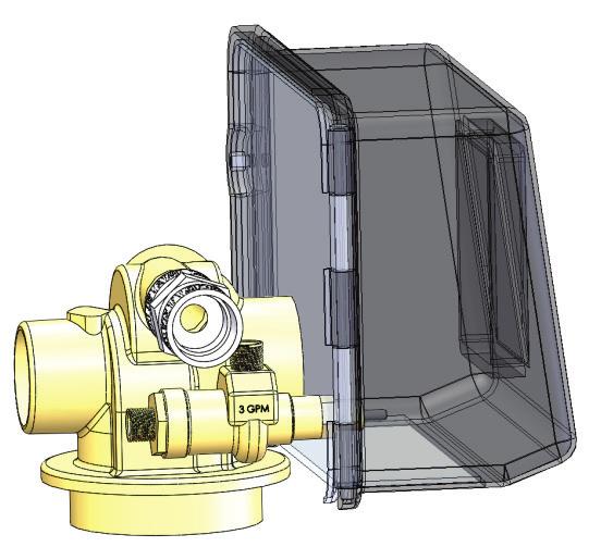
5 Section 1.3 SYSTEM ILLUSTRATION Control Box Control Interface Inlet Pressure Gauge Pump Bypass Valve Pump ph Probe (Not Visible) Inlet Service Valve Emergency Water Connection HDPE Stand Flow Sensor Temperature Sensor Hose Bibb Outlet Service Valve Flow Meter 4-40 GPM Fiberglass Mount Flow Switch Leak Detector Nurse Station Remote fax 3
6 Section 1.4 SYSTEM COMPONENTS See illustration on previous page OIT (Operator Interface Terminal): This interface terminal contains all operating features. These include viewing all monitored values and logs as well as the ability to set up custom parameters. Nurse Station Remote: Alarms can be visual and/or audible and may be reset. Staff are able to turn on the Chlorine Timer and view system parameters. Flow Switch: Monitors if water is flowing through pump or not. An electrical signal is generated if flow is present. Flow Meter: Monitors the amount of flow in gallons per minute (GPM). When pump is on, a visual flow reading can be done by aligning the top of the stainless-steel cylinder to the gallon engravings on side of the flow meter. Flow Sensor: Digitally monitors the flow, and a signal is sent to the Control Panel and converted into a digital display of that flow in the user s choice of units of measure (GPM or LPM). ph Probe: Monitors the ph of the city water pre-booster pump. Hose Bib: Convenient water faucet for multiple applications. Pressure Sensor: The Pressure Sensor maintains the pressure setting programed into the drive s control, and should be placed downstream as close to the RO as possible. Water Temperature Monitor: Monitors the water temperature post blend valve on the post boost pump side of the device. The factory default to alarm is set at 90 degrees Fahrenheit but these parameters can be changed in the maintenance menus. Leak Detector with Auto Shut Off: The Leak Detector is placed on the floor and used to monitor for leaks in the water treatment room and will automatically turn off the municipal boost system and close the inlet water valve when a leak is detected. It should be placed at the lowest level of the floor where water will naturally travel. When liquid is detected the water inlet valve closes and the pump will power off. To clear leak detection, clean up water spill. Gently shake the sensor to remove water sales@specialtyh2o.com fax 4

7 Section 2.1 MONITORING OPERATION SCREEN Select OPERATE to navigate to the main OPERATION SCREEN. COLD WATER BYPASS: Automated valve position is monitored and displayed. LEAK DETECTOR*: Monitored by the leak detection probe. BOOST SYSTEM: Monitored by the flow switch post booster pump. TEMPERATURE*: Monitored at the temperature sensor post booster pump. RO SUPPLY: Monitored at the pressure sensor post final media tank. FLOW: Monitored by a turbine flow sensor post booster pump. EBCT*: Calculated using live flow data and stored carbon volume data. PH*: Monitored at the ph probe pre-booster pump. *(Indicates out of range value will generate an alarm status) sales@specialtyh2o.com fax 5

8 Section 2.2 MONITORING SYSTEM DATA SCREEN From the Operation screen select SYSTEM DATA to navigate to the system data screen. The SYSTEM DATA screen allows the user to monitor all pre-treatment pressures in real time. Temperatures of pre and post blending valve are monitored and displayed. Delta pressure drops across filters and media tanks are calculated and displayed in real time. Out of range Delta Pressures produce a banner alert across the OIT sales@specialtyh2o.com fax 6


9 Section 2.3 MONITORING SYSTEM PERAMETERS SCREEN The SYSTEM PERAMETERS SCREEN displays a menu of the pre-treatment components. Navigating to each component displays an illustration of that component, current monitored values of that component, SWT item and part numbers for each component or assembly, and the QR code for use with a mobile device that will download the operator s manual as a PDF file sales@specialtyh2o.com fax 7
 if a particular media tank failed to complete its cycles or if the ACTUAL volume of")

10 Section 2.4 MONITORING MEDIA DATA SCREEN The MEDIA DATA SCREEN can monitor the backwash/regeneration data of up to six media tanks. The STATUS column will alert the user (including an alarm at the Nurse Station Remote) if a particular media tank failed to complete its cycles or if the ACTUAL volume of water used (measured by the flow meter) is outside the tolerance of the pre-calculated value. The CALCULATED volume value is populated at initial set up using the programed cycle times of the control head and the value of the flow control valve attached to the drain of the control head. The TOTAL column represents lifetime volume sales@specialtyh2o.com fax 8


11 Section 2.5 MONITORING FLOW DATA SCREEN System water usage is monitored at the FLOW DATA SCREEN. The values of VOLUME PROCESSED are obtained by adding together the water consumed by the cycles (BACKWASH, forward flush and regeneration) of the media tanks and the RO USAGE. The top half of the screen maintains lifetime totals of usage. The bottom half of the screen values designed to be reset monthly. This temporary data can be RESET to zero by the user fax 9
12 Section 2.6 MONITORING EVENT LOG SCREENS Upon entering the EVENT LOG SCREEN the three options are PRE TREATMENT LOG, REVERSE OSMOSIS LOG, and POST TREATMENT LOG. CHLORINE TEST LOG: Records the dates and times of completed chlorine test cycles. MEDIA TANK BACKWASH LOG: Records the dates and times of media tank backwash cycles. PRESSURE HOLDING TEST LOG: Records the dates and times of both automated and initiated pressure holding tests. SYSTEM FAULT LOG: Records the dates and times of system errors and faults. RO SYSTEM FAULT LOG: Records the dates and times of the alarm states transmitted by the reverse osmosis machine. RO CLEAN LOG: Records the dates and times when an RO clean cycle was initiated fax 10
13 Section 3.1 TESTING CHLORINE TESTING 1. From the Operation Screen select CHLORINE TIMER to start the timer. The red indicator and the cancel button will appear. At any time during the chlorine timer process the cancel button may be used to stop the process. 2. Once the chlorine timer has counted down (settable from minutes), an audible alarm will sound prompting the user to collect the sample at the sample station. The screen will also display TEST COMPLETE and END OF DAY buttons. NOTE: The Test Complete button will reset the Chlorine Timer and start the shift interval timer for the next scheduled chlorine test (settable from 3-5 hours). NOTE: The End of Day button will reset the alarm and turn the chlorine timer off. This is typically done after the last chlorine sample is taken for the day. 3. The SHIFT INTERVAL and TEST CYCLE timers may be changed by entering the SYSTEM MAINTENANCE menu and selecting the CHLORINE TIMER SETUP menu fax 11
14 Section 3.2 TESTING PRESSURE HOLDING TEST 1. Press Pressure Hold Test button. 2. The following screen will appear. There is no user input involved. 3. Test will complete within 1 minute and test result will be logged in Pressure Holding Test log. Pressure Held: Is the pressure the system is at when Pressure Holding Test was initiated. Actual Pressure: The actual pressure in the pre-treatment system during test interval. Difference: The amount of pressure loss the system has sensed. Remaining Test Time: Is the amount of time remaining before the test is completed & logged. NOTE: The controller performs this test by closing the pre-booster pump automated leak detector valve and the RO inlet valve. To pinpoint a leak in the system you can manually close the outlet valves of the media tanks (starting at the last tank and moving toward the booster pump) and run the test after each closed valve to identify the leaking component sales@specialtyh2o.com fax 12
15 Section 4.1 INTERFACE SETUP RANGES AND ALARMS RANGE OF PARAMETERS SETUP Empty Bed Contact Time Minutes Flow Volume 5-35 Gallons Per Minute Shift Interval 3-4 Hours Test Cycle Minutes Low: Range Degrees F Temperature Set Point High: Range Degrees F Low: Range PH PH Set Point High: Range PH Pump Pressure Range PSI Pressure Test Set Point Range PSI Alarm Cycle 3-60 Seconds Alarm Repeat 1-10 Minutes Auto Off 5-90 Minutes Shift Interval 3-4 Hours Test Cycle Minutes DLFC- Drain Line Flow Control 5-85 GPM Backwash Cycle 2-60 Minutes Rapid Rinse Cycle 2-60 Minutes BLFC- Brine Line Flow Control 2-12 GPM Brine Draw 2-60 Minutes Brine Fill 2-60 Minutes Carbon Volume 4-21 Cubic Feet Temperature Set Point Low: When feed water temperature reaches this value a low level reminder banner is generated alerting user to possible blend valve failure or adjustment. This feature may be used as a reminder to put blend valve back inline when bypassed during summer months. High: When feed water temperature reaches this value alarm is generated and Cold Water Bypass valve is opened in attempt to cool system. PH PH Fault Bypass & Flow Switch Bypass buttons should be left in the OFF position. These parameters should only be bypassed in the event of an emergency. Pump Pressure If the pressure sensor post booster pump fails (sensors fail to the high side 100psi), the controller will adjust the pump hertz to a preset medial level for safety. Pressure Set Test Point This range represents the allowable leak of pressure during the Pressure Holding Test. An alarm would be generated upon exceeding this set point sales@specialtyh2o.com fax 13


16 Section 4.2 INTERFACE SETUP - ACCESS User is required to enter username & password to access System Maintenance screens. Username determines the access level to critical parameters. TECH: Gains access to general setup parameters. User Setup menu options. 1. Press the Login Button from the Main Menu. 2. Touch black area to right of User ID. A popup screen will appear. 3. Use keypad to enter User ID (TECH) and press ENT. 4. Touch black area to right of user Password. A popup screen will appear. 5. Use keypad to enter Password (4441), press ENT and then press OK NOTE: The System Maintenance button is now available on the lower right portion of the Main Menu screen. 6. Press System Maintenance to enter Setup. Note: System will log user out of system in 5 minutes of in-activity sales@specialtyh2o.com fax 14
17 Section 4.3 INTERFACE SETUP SYSTEM MAINTENANCE SCREEN RANGE OF PARAMETERS Contact Time Minutes Flow Volume 5-35 Gallons Per Minute Shift Interval 3-4 Hours Test Cycle Minutes Temperature Set Point Low: Range Degrees F High: Range Degrees F PH Set Point Low: Range PH High: Range PH Pump Pressure Range PSI Pressure Test Set Point Range PSI sales@specialtyh2o.com fax 15

18 Section 4.4 INTERFACE SETUP USER SETUP 1. Press User Setup button. 2. The following menu options will appear. Press inside the blue box to set each parameter. A popup screen will appear. 3. Enter a value within the parameter ranges and Press ENT to save value. 4. Once all the parameters have been set, Press COMPLETE to return to System Maintenance menu. Temperature Set Point Low: When feed water temperature reaches this value a low level reminder banner is generated alerting user to possible blend valve failure or adjustment may be required. May be used as a reminder to put blend valve back online when bypassed during summer months. High: When feed water temperature reaches this value an alarm is generated and Cold Water Bypass valve is opened in an attempt to cool system. PH Set Point Low: When feed water PH reaches this value a low level reminder banner is generated alerting user to feed water changes that could have detrimental effects on the operation of reverse osmosis equipment. High: When feed water PH reaches this value a low level reminder banner is generated alerting user to feed water changes that could have detrimental effects on the operation of reverse osmosis equipment. Pump Pressure Sets the pressure in PSI to the value pump should maintain when active. Pressure will be controlled via an electronic pressure sensor. Expected pump pressure will be maintained at location nearest to the psi sensor. PSI Test Set Point Sets the amount of pressure loss that can be sensed before a pressure test failure is generated. PH Fault Bypass Bypasses all PH alarms, monitoring is still active. PH probe should be online at all times. Flow Switch Bypass Bypasses the Flow Switch and allows pump to run in pressure control mode. No run dry protection is available if bypassed sales@specialtyh2o.com fax 16

19 Section 4.5 INTERFACE SETUP CHLORINE TIMER SETUP 1. Press Chlorine Setup button. 2. The following menu options will appear. Press inside the blue box to set each parameter. A popup screen will appear. 3. Enter a value within the parameter ranges and Press ENT to save value. 4. Once all the parameters have been set, Press COMPLETE to return to System Maintenance menu. Shift Interval: Is the amount of time between the last completed Chlorine Test and when the next Test Cycle is initiated. Test Cycle: Is the amount of time when the RO remains ON until an audible prompt is generated. RO remains ON until user acknowledges test has been completed sales@specialtyh2o.com fax 17

20 Section 4.6 INTERFACE SETUP EMPTY BED CONTACT TIME SETUP 1. Press EBCT Setup button. 2. The following menu options will appear. Press inside the blue box to set each parameter. A popup screen will appear. 3. Enter a value within the parameter ranges and Press ENT to save value. 4. Once all the parameters have been set, Press COMPLETE to return to System Maintenance menu. Contact Time: Enter your facilities standard for Empty Bed Contact Time. A.A.M.I. Standard is 10 Minutes. Flow Volume: Is the total flow volume of reverse osmosis system. Flow Volume (gpm) = RO Drain + RO Product. Carbon Volume Required: Is the minimum calculated amount of carbon required to meet EBCT. Actual Carbon Volume: Is the total amount of carbon that is present in existing system. If Actual Carbon Volume is less than Carbon Volume Required and EBCT Alarm will occur sales@specialtyh2o.com fax 18

21 Section 4.7 INTERFACE SETUP MEDIA TANK SETUP 1. Press Media Tank Setup button. 2. The following menu options will appear. Press Tank # that is to be programmed. 3. Press Carbon Worker and press Next. NOTE: Tank 1 is always the first media tank in sequence regardless of its media contents. Example: Use FIG 1 for reference. Tank 1 = Carbon Worker Tank 2 = Carbon Polisher Tank 3 = Softener sales@specialtyh2o.com fax 19
22 Section 4.7 INTERFACE SETUP MEDIA TANK SETUP 4. Press inside the blue box to set each parameter. A popup screen will appear. 5. Enter a value within the parameter ranges and Press ENT to save value. 6. Once all the parameters have been set, Press COMPLETE to return to Media Tanks menu. 7. Repeat steps 1-6 until all media tanks are programmed. Un-programmed tank numbers will be ignored in all monitoring and reporting activities. NOTE: Only required parameters based on media selection will appear visible in setup screens. For instance, regeneration type tanks such as a softener would have additional data fields to program as seen in Fig 2. DLFC Drain Line Flow Control: Is a flow restrictor placed on the drain line of a media tank controller to control the backwash volume Fig 3. The DLFC should have a GPM value stamped, stenciled, engraved or inked on side of device. See Fig 4. Backwash: The amount of time the media tank controller is programmed for in Backwash mode. Rapid Rinse: The amount of time the media tank controller is programmed for in rapid rinse mode. BLFC Brine Line Flow Control: Is a flow restrictor placed in the injector assembly of a media tank controller to control the brine cycle volume Fig 5. The DLFC should have a GPM value stamped, stenciled, engraved or inked on side of device. See Fig 6. Brine Draw: The amount of time the media tank controller is programmed to draw brine into media tank. Brine Fill: The amount of time the media tank controller is programmed to fill the brine tank. Carbon Volume: Is the total amount of carbon that is in tank being programmed sales@specialtyh2o.com fax 20


23 Section 4.7 INTERFACE SETUP MEDIA TANK SETUP Fig 3 Fig 2 Fig 5 Fig 4 Fig 6 DLFC Brine Injector BLFC sales@specialtyh2o.com fax 21


24 Specialty Water Technologies, Inc. Operation Manual Section 5.1 MCB w/pre-treatment Monitor SPECIFICATIONS - DIMENSIONS & WEIGHT Size: H X 31 W X 24.4 D Weight: 190 LB. Dry H D W sales@specialtyh2o.com fax 22
25 Section 5.2 SPECIFICATIONS ELECTRICAL AND WATER REQUIREMENTS Inlet Water Connection: Inlet water piping capable of delivering 20 GPM (Gallons per Minute), and PSI (Pounds per Square Inch) pressure. Feed Water Connection: The connection from the water feed side of the Municipal Boost to the trunk line is normally 1 ½ sch. 80 PVC. (Occasionally 1 piping is used) Electrical Requirements: 2HP Pump Version: volt, single phase 20 AMP dedicated circuit w/30a twist N lock receptacle. 3HP Pump Version: volt, single phase 25 AMP dedicated circuit w/30a twist N lock receptacle sales@specialtyh2o.com fax 23
26 Section 6.1 ROUTINE MAINTENANCE Routine inspection of the system is recommended. Follow all facility procedures regarding regular inspection of electrical equipment. Quarterly system should be inspected as follows: Unplug from wall outlet and inspect plug for signs of electrical burn. Inspect plug for frayed wires. Repair and replace as needed. Inspect and clean fan vents on each side of the control box. Ensure adequate ventilation. Wipe exterior and inspect pump for dust and debris accumulation on top of fan shroud. Keep fan shroud clean. Inspect and clean glass on flowmeter for visual clarity. Over the course of time, the variation of temperatures, pressure and vibration may cause some threaded fittings to loosen. Tighten only enough to stop the leak. Overtightening may cause damage to the fitting. Check hand-tightened fittings (valve couplings) for leaks. Hand tighten only enough to stop leak. Overtightening may cause damage to the valve union. Inspect the flange mounts on each side of the pump for leaks. Tighten clamp bolts to 22 ft/lbs or just enough to stop the leak fax 24

 4. Flip the Main breaker to the ON position.")
27 Section 6.2 REBOOT PROCEDURE Reboot Procedure This may be used to reboot the boost system if one of the following fault detection codes is present on the VFD drive display. CrF IF3 blf OCF IF1 IF4 EEF SCF SOF IF2 tnf 1. Open the control box. 2. Flip the Main breaker to the OFF position. 3. Wait 45 seconds. (Indicator light on VFD Drive must be completely out) 4. Flip the Main breaker to the ON position. Error code should now be reset and system should resume normal operation VFD Display Indicator Light Main Breaker fax 25
28 NOTES: fax 26


29 MCB w/pre-treatment Monitor System Rev. 12_2017 Manual P/N: OM-K-A-MCB-PRE fax
1020 Industrial Drive, Orlinda, TN fax
 Operation Manual Tank Distribution System A-UPT Series 615-654-4441 sales@specialtyh2o.com 615-654-4449 fax TABLE OF CONTENTS Section 1 GENERAL 1.2 Warnings and Cautions... 1 1.2 Theory of Operation...
Concentrate Distribution System (Stand Mounted) A-CDS-70-X & A-CDS-TANK-X-ST Industrial Drive, Orlinda, TN 37141
 A-CDS-70-X & A-CDS-TANK-X-ST Industrial Drive, Orlinda, TN 37141") 0 Operation Manual Concentrate Distribution System (Stand Mounted) A-CDS-70-X & A-CDS-TANK-X-ST 615-654-4441 sales@specialtyh2o.com 615-654-4449 fax TABLE OF CONTENTS Section 1 GENERAL 1.1 Warnings and
0 Operation Manual Concentrate Distribution System (Stand Mounted) A-CDS-70-X & A-CDS-TANK-X-ST 615-654-4441 sales@specialtyh2o.com 615-654-4449 fax TABLE OF CONTENTS Section 1 GENERAL 1.1 Warnings and
Operation Manual. Carbon Filtration Industrial Drive, Orlinda, TN fax
 Operation Manual Carbon Filtration 615-654-4441 sales@specialtyh2o.com 615-654-4449 fax TABLE OF CONTENTS Section 1 GENERAL 1.1 Warnings and Cautions... 1 1.2 Theory of Operation... 2 1.3 System Illustration...
1020 Industrial Drive, Orlinda, TN fax
 Operation Manual Ultrafiltration for High Purity Distribution K-A-HPTUF Series 615-654-4441 sales@specialtyh2o.com 615-654-4449 fax TABLE OF CONTENTS Section 1 GENERAL 1.1 Warnings and Cautions... 1 1.2
Reverse Osmosis System Installation Guide and Operation Manual.
 Reverse Osmosis System Installation Guide and Operation Manual. Table of Contents 1 Introduction...2 2 Installation...3 2.1 Feed water connection...3 2.2 Permeate and concentrate plumbing...3 2.3 Electrical
Installation and Instructions 2. Product Features 3-6. Key Pad Functions 7. Distributor Information Programming Guide 8. Master Programming Guide 9-14
 Installation and Instructions 2 Product Features 3-6 Key Pad Functions 7 Distributor Information Programming Guide 8 Master Programming Guide 9-14 Dimensional Drawing 15 D-STC & D-SMM Valve Assembly 16-17
Softeners Clack Model V125DTH Medical / Industrial Series Operation and Service Manual
 Softeners Clack Model V125DTH Medical / Industrial Series Operation and Service Manual www.ameriwater.com 800-535-5585 AmeriWater LLC 3345 Stop 8 Rd. Dayton, OH 45414 Clack Softener Manual, 98-0180 Rev.
Declining Weight Blending System Quick Start Manual E Main St Marshall, IL Phone: Fax: Website:
 Declining Weight Blending System Quick Start Manual 12285 E Main St Marshall, IL 62441 Phone: 217-826-6352 Fax: 217-826-8551 Website: www.yargus.com P a g e 2 MAIN SCREEN The MAIN SCREEN on the cover page
Installation, Operation and Maintenance Instructions for Electronically Controlled Pressurisation Units
 Installation, Operation and Maintenance Instructions for Electronically Controlled Pressurisation Units Models: EPS Single Pump EPT Twin Pump EPS-HP EPT-HP Single Pump High Pressure Twin Pump High Pressure
Model PSI Compressor with 3-Gallon Air Tank 12VDC
 Model 6350 150 PSI Compressor with 3-Gallon Air Tank 12VDC IMPORTANT: It is essential that you and any other operator of this product read and understandd the contents of this manual before installing
INSTALLATION. and INSTRUCTION MANUAL. for QUALITY AIR BREATHING SYSTEMS. Model 50 Systems Outfitted with ABM-725 Monitor C O M P A N Y
 INSTALLATION and INSTRUCTION MANUAL for QUALITY AIR BREATHING SYSTEMS Model 50 Systems Outfitted with ABM-725 Monitor M A R T E C H S E R V I C E S C O M P A N Y OFFICE: (507) 843-4700 P.O. BOX 7079 Toll
DRS4-RM Manual. Set Up Instructions for DRS4 Series Single Tank
 Set Up Instructions for DRS4 Series Single Tank Inspect the packaging of the equipment to confirm that nothing was damaged during shipping. (Figure 1) Remove the resin tank(s) and valve(s) from the packaging.
PROPORTIONING VALVE. Model 150 INSTRUCTION MANUAL. March 2017 IMS Company Stafford Road
 PROPORTIONING VALVE Model 150 INSTRUCTION MANUAL March 2017 IMS Company 10373 Stafford Road Telephone: (440) 543-1615 Fax: (440) 543-1069 Email: sales@imscompany.com 1 Introduction IMS Company reserves
PumpAgents.com - Click here for Pricing/Ordering Nominal psi (bar) Cut-In Cut-Out
 Cut-In Cut-Out") PumpAgents.com - Click here for Pricing/Ordering Model 31670-Series Dual Max 7.5 GPM (28 LPM) AUTOMATIC TWO STAGE WATER SYSTEM WITH ACCUMULATOR TANK AND PUMPGARD STRAINER IDEAL FOR PLEASURE AND COMMERCIAL
PumpAgents.com - Click here for Pricing/Ordering Model 31670-Series Dual Max 7.5 GPM (28 LPM) AUTOMATIC TWO STAGE WATER SYSTEM WITH ACCUMULATOR TANK AND PUMPGARD STRAINER IDEAL FOR PLEASURE AND COMMERCIAL
IMPORTANT SAFETY INSTRUCTIONS
 IMPORTANT SAFETY INSTRUCTIONS CAUTION - To reduce risk of electrical shock: - Do not disassemble. Do not attempt repairs or modifications. Refer to qualified service agencies for all service and repairs.
Accu-Tab Systems 2000 P Series by Axiall Corporation
 Accu-Tab Systems 2000 P Series by Axiall Corporation Installation and Operating Instructions Models 2075 P 2150 P For NSF/ANSI-Standard 61 NSF STANDARD 61 applications use NSF/ANSI Standard 60 listed Axiall
ECONORESS ELECTRONIC EPS & EPT - ENHANCED PRESSURISATION SET INSTALLATION OPERATION & MAINTENANCE DOCUMENTATION
 ECONORESS ELECTRONIC EPS & EPT - ENHANCED PRESSURISATION SET INSTALLATION OPERATION & MAINTENANCE DOCUMENTATION OCT2010 STOKVIS ENERGY SYSTEMS 96R WALTON ROAD EAST MOLESEY SURREY KT8 0DL TEL: 020 87833050
250C-IG COMPRESSOR KIT 12V PART NO C-IG COMPRESSOR KIT 24V PART NO
 250C-IG COMPRESSOR KIT 12V PART NO. 25050 250C-IG COMPRESSOR KIT 24V PART NO. 25058 IMPORTANT: It is essential that you and any other operator of this product read and understand the contents of this manual
Performa Cv Twin Alternating and High Flow Systems. Manual Supplement
 Performa Cv Twin Alternating and High Flow Systems Manual Supplement Table of Contents 1.0 Installation and Start-Up.............. 3 Water Line Connection Brine Tank Turbine Connection Connecting Manifold
100C Air Compressor Kit
 10010 100C Air Compressor (standard mounting bracket, CE Spec) 10014 100C Air Compressor (no leader hose or check valve, CE Spec) 10016 100C Air Compressor (with Omega Bracket, CE Spec) IMPORTANT: It is
250C-IG COMPRESSOR KIT 12V PART NO C-IG COMPRESSOR KIT 24V PART NO
 250C-IG COMPRESSOR KIT 12V PART NO. 25050 250C-IG COMPRESSOR KIT 24V PART NO. 25058 IMPORTANT: It is essential that you and any other operator of this product read and understand the contents of this manual
Duplex Commercial Softeners
 Duplex Commercial Softeners Installation, Operation & Maintenance Guide Manual 003.1 Contents Page 1. Unpacking Instructions 3 2. Installation 4 Pre-installation checks Fitting the bottom distribution
Accu-Tab Systems 1000 Series by Axiall Corporation
 Accu-Tab Systems 1000 Series by Axiall Corporation Installation and Operating Instructions Model 1050 DANGER: DO NOT MIX CHEMICALS! The Accu-Tab chlorinator is designed for use with Axiall approved tablets
400C & 450C DUAL PERFORMANCE VALUE PACKS
 (Chrome) PART NO. 40013 (Silver) PART NO. 45012 (Chrome) PART NO. 45013 IMPORTANT: It is essential that you and any other operator of this product read and understand the contents of this manual before
420C AIR COMPRESSOR KIT PART NO C AIR COMPRESSOR KIT PART NO
 420C AIR COMPRESSOR KIT PART NO. 42042 460C AIR COMPRESSOR KIT PART NO. 46043 420C 460C IMPORTANT: It is essential that you and any other operator of this product read and understand the contents of this
User Manual for the Mars Calibration Bench
 User Manual for the Mars Calibration Bench Fall 2013 Table of Contents Table of Contents Table of Contents... iii Introduction... v Chapter 1: The Mars Calibration Bench... 1 What Is the Mars Calibration
MP15 Jockey Pump Controller
 Setup and Operating Instructions MP15 Jockey Pump Controller This manual provides general information, installation, operation, maintenance, and system setup information for Metron Model MP15 Jockey Pump
Commercial Softeners. Installation, Operation & Maintenance Guide. Manual 002.1
 Commercial Softeners Installation, Operation & Maintenance Guide Manual 002.1 Contents Page 1. Unpacking Instructions 3 2. Installation 3 Pre-installation checks Fitting the bottom distribution system
Owners Manual Models: 075-AQF-CX. Aquatrol Backwashing Catalytic Carbon Filter. Visit us online at.
 Visit us online at www.uswatersystems.com Aquatrol Backwashing Catalytic Carbon Filter Owners Manual Models: 075-AQF-CX REVISION # 1.0 REVISION DATE October 11, 2017 US Water Systems, Inc. 1209 Country
CCT-7320/ROC-2313 Reverse Osmosis Controller
 CCT-7320/ROC-2313 Reverse Osmosis Controller 1 General The instrument is a combined control instrument of a reverse osmosis controller and an on-line conductivity instrument. It can perform the operation
200 PSI COMPRESSORS - MODEL NUMBERS
 200 PSI COMPRESSORS - MODEL NUMBERS 380C AIR COMPRESSOR KIT PART NO. 38033 480C AIR COMPRESSOR KIT PART NO. 48043 380C 480C IMPORTANT: It is essential that you and any other operator of this product read
Light Commercial Reverse Osmosis System. EE-1000 Manual
 Light Commercial Reverse Osmosis System EE-1000 Manual Nimbus Water Systems 41840 McAlby Court, Suite A Murrieta, CA 92562 800-451-9343 Fax 951-894-2801 www.nimbuswater.com Nimbus Water Systems 1 EE-1000
INSTRUCTION MANUAL. Automatic Water Softener System. Model: PSE-08. Xsential Water Filtration Systems
 INSTRUCTION MANUAL Automatic Water Softener System Model: PSE-08 Xsential Water Filtration Systems 78 Daly Street Ascot Western Australia 6104 Ph: 1300 366 295 Fax: (08) 9277 2266 www.xsential.com.au Welcome
RAM Operation Manual. Worldwide Manufacturer of Gas Detection Solutions
 RAM 4021 Operation Manual Worldwide Manufacturer of Gas Detection Solutions TABLE OF CONTENTS RAM 4021 For Your Safety... 2 Description.... 2 Setup Mode.... 2 Lights/Alarms.... 3 Operation.... 4 Calibration....
444C DUAL PERFORMANCE VALUE PACK
 (Chrome) PART NO. 44432 IMPORTANT: It is essential that you and any other operator of this product read and understand the contents of this manual before installing and using this product. SAVE THIS MANUAL
SpectraPure PUMPED RO SYSTEMS (PSP) User s Manual for PSP-1500 Systems
 User s Manual for PSP-1500 Systems") SpectraPure PUMPED RO SYSTEMS (PSP) User s Manual for PSP-1500 Systems 2 3 PSP-1500 SYSTEM DESCRIPTION Reverse Osmosis RO Reverse Osmosis utilizes the unique properties of a semi-permeable membrane to
SpectraPure PUMPED RO SYSTEMS (PSP) User s Manual for PSP-1500 Systems 2 3 PSP-1500 SYSTEM DESCRIPTION Reverse Osmosis RO Reverse Osmosis utilizes the unique properties of a semi-permeable membrane to
RAM 4021-PR. Operation Manual. Worldwide Manufacturer of Gas Detection Solutions
 RAM 4021-PR Operation Manual Worldwide Manufacturer of Gas Detection Solutions TABLE OF CONTENTS RAM 4021-PR For Your Safety... 2 Description.... 2 Setup Mode.... 2 Lights/Alarms.... 3 Operation.... 4
FAULT CODE TROUBLESHOOTING INDEX
 FAULT CODE TROUBLESHOOTING INDEX 1. Display indicates Change Filters 2. Display indicates Drip Tray Full Continuous Alarm will Sound 3. Display indicates Cold Fault 4. Display indicates Hot Fault 5. Display
3 GALLON, OILLESS PANCAKE COMPRESSOR INSTRUCTIONS. Item #31289
 3 GALLON, OILLESS PANCAKE COMPRESSOR INSTRUCTIONS Item #31289 The EASTWOOD 3 GALLON, OILLESS PANCAKE COMPRESSOR, with an Integral Air Regulator, efficiently supplies all compressed air requirements for
200 PSI HIGH-FLOW AIR SOURCE KIT
 200 PSI HIGH-FLOW AIR SOURCE KIT 50% Duty Compressor on 2.0 Gallon Air Tank PART NO. 20008 IMPORTANT: It is essential that you and any other operator of this product read and understand the contents of
AFDXXX(X)AC Series Operators Manual Please read this manual thoroughly before attempting to operate your water maker.
AC Series Operators Manual Please read this manual thoroughly before attempting to operate your water maker.") AFDXXX(X)AC Series Operators Manual Please read this manual thoroughly before attempting to operate your water maker. E & O E Danger High Voltage AFDXXX(X) Series water makers operate on a 240vAC electricity
AFDXXX(X)AC Series Operators Manual Please read this manual thoroughly before attempting to operate your water maker. E & O E Danger High Voltage AFDXXX(X) Series water makers operate on a 240vAC electricity
Installation, Operation and Maintenance Instructions for Electronically Controlled Pressurisation Units Digital Range
 Installation, Operation and Maintenance Instructions for Electronically Controlled Pressurisation Units Digital Range Models: DS 126 Single Pump / Single System DT 126 Twin Pump / Single System DS 160
RAM Operation Manual. Worldwide Manufacturer of Gas Detection Solutions
 RAM 4021 Operation Manual Worldwide Manufacturer of Gas Detection Solutions TABLE OF CONTENTS RAM 4021 For Your Safety... 2 Description.... 2 Setup Mode.... 2 Lights/Alarms.... 3 Operation.... 4 Calibration....
TECHNICAL DATA. Q = C v P S
 Page 1 of 13 1. DESCRIPTION The Viking 6 Model G-6000 Dry Valve Riser Assembly consists of a small profile, light weight, pilot operated valve that is used to separate the water supply from the dry sprinkler
RAM 4021 Operation Manual
 RAM 4021 Operation Manual Worldwide Manufacturer of Gas Detection Solutions TABLE OF CONTENTS RAM 4021 For your safety...3 Description...3 Set-up mode...4 Annunciator lights/alarms...4 Operation...5 Calibration...6
O&M Receiving and Inspection. Storage of Water Treatment Media
 O&M 105.1 Receiving and Inspection 1. Equipment should be checked against the Bill of Lading to verify that the number of pieces received matches those shipped. 2. Equipment should be carefully inspected
42045 Heavy Duty ADA Base Model Kit: 85/105 PSI (ADA Compressor Only) Heavy Duty ADA Base Model Kit: 110/145 PSI (ADA Compressor Only)
 Heavy Duty ADA Base Model Kit: 110/145 PSI (ADA Compressor Only)") 42045 Heavy Duty ADA Base Model Kit: 85/105 PSI (ADA Compressor Only) 42047 Heavy Duty ADA Base Model Kit: 110/145 PSI (ADA Compressor Only) 45052 Constant Duty ADA Base Model Kit: 85/105 PSI (ADA Compressor
42045 Heavy Duty ADA Base Model Kit: 85/105 PSI (ADA Compressor Only) 42047 Heavy Duty ADA Base Model Kit: 110/145 PSI (ADA Compressor Only) 45052 Constant Duty ADA Base Model Kit: 85/105 PSI (ADA Compressor
Touch Screen Guide. OG-1500 and OG Part # T011
 Touch Screen Guide OG-1500 and OG-2000 Part # 9000000.T011 Effective 11/2010 External View Internal View 1. Transducer Banks 2. Oxygen Sensor 3. PLC These are the two manifolds with three (3) transducers
200 PSI FAST-FILL AIR SOURCE KIT
 200 PSI FAST-FILL AIR SOURCE KIT 55% Duty Compressor on 2.0 Gallon Air Tank PART NO. 20007 IMPORTANT: It is essential that you and any other operator of this product read and understand the contents of
NORMAL OPERATING DISPLAYS GENERAL OPERATION
 SunTapWat e rsys t e ms WS1Cl ac kwat e rsof t ne r Owne r smanual MAIN COMPONENTS Your water treatment system is a point of entry (POE) system composed of three components: A. The control valve and computer
TECHNICAL DATA. Q= Cv S
 Page 1 of 13 1. DESCRIPTION The Viking 4 inch Model G-4000 Dry Valve Riser Assembly consists of a small profile, light weight, pilot operated valve that is used to separate the water supply from the dry
97C COMPRESSOR KIT 12V PART NO C COMPRESSOR KIT 24V PART NO C COMPRESSOR KIT PART NO
 97C COMPRESSOR KIT 12V PART NO. 00097 97C COMPRESSOR KIT 24V PART NO. 02497 98C COMPRESSOR KIT PART NO. 00098 97C 98C IMPORTANT: It is essential that you and any other operator of this product read and
R E D I C O N T R O L S
 R E D I C O N T R O L S Operation & Maintenance Manual Portable Service Purger for Low Pressure Chillers Model: PSP-LP-1B For Refrigerants R-11, R-113, R-114 & R-123 & Other Similar Refrigerants File Literature
MODEL NUMBER: PSI AIR SOURCE KIT 200 PSI Compressor on 2.0 Gallon 200 PSI Air Tank
 IMPORTANT SAFETY INSTRUCTIONS CAUTION - To reduce risk of electrical shock or Electrocution: MODEL NUMBER: 20008 200 PSI AIR SOURCE KIT 200 PSI Compressor on 2.0 Gallon 200 PSI Air Tank IMPORTANT: It is
PART 1 GENERAL..2 Components of the gas chlorination system include, but are not limited to the following:
 PART 1 GENERAL 1.1 DESCRIPTION.1 This section includes the supply, delivery and installation, testing and placement into operation of a gas chlorination system, and appurtenances as specified herein and
MODEL NUMBER: M20005 AIR SOURCE KIT. 30% Duty Compressor on. 2.0 Gallon Air Tank SAVE THIS MANUAL FOR FUTURE REFERENCE
 MODEL NUMBER: M20005 AIR SOURCE KIT 30% Duty Compressor on 2.0 Gallon Air Tank SAVE THIS MANUAL FOR FUTURE REFERENCE USER MANUAL IMPORTANT SAFETY INSTRUCTIONS CAUTION - To reduce risk of electrical shock
Matrix Pre-Treatment System
 Better Water LLC Matrix Pre-Treatment System R x Only 21 CFR 801.109(b)(1) rev. Feb 2017 REA 2333 Better Water LLC. All rights reserved. The content of this manual is the intellectual property of Better
TECHNICAL DATA 3 MODEL G-3000 DRY VALVE RISER ASSEMBLY
 Page 1 of 13 1. DESCRIPTION The Viking 3 Model G-3000 Dry Valve Riser Assembly is equipped with a small profile, light weight, pilot operated valve that is used to separate the water supply from the dry
CONGRATULATIONS ON YOUR PURCHASE OF YOUR THUNDER COMPRESSOR For your personal safety please read, understand and follow the information provided in
 CONGRATULATIONS ON YOUR PURCHASE OF YOUR THUNDER COMPRESSOR For your personal safety please read, understand and follow the information provided in this instruction manual. 1 CONTENTS 3. Safety Precautions
Autotrol Performa ProSoft
 Autotrol Performa ProSoft With 960 Series Control 5-Cycle Conditioner 5-Cycle FA Filter Water Conditioning Control System Installation, Operation and Maintenance Manual Table of Contents Installation.....................................
TECHNICAL DATA Q = C. v P S. 2 Model G-2000 Dry valve. Page 1 of 13
 Page 1 of 13 1. Description The Viking 2 Model G-2000 Dry Valve Riser Assembly consists of a small profile, light weight, pilot operated valve that is used to separate the water supply from the dry sprinkler
UBEC 1AT. AUTO TANK Fill System Installation, Operation, & Setup Instructions
 Document Number: XE-ATA5PM-R1A UBEC 1AT AUTO TANK Fill System 08899155 Installation, Operation, & Setup Instructions Rev170906-EB-FRC PHYSICAL: 1302 WEST BEARDSLEY AVE ELKHART, IN 46514 WWW.ELKHARTBRASS.COM
DOMESTIC HOT WATER TEMPERATURE CONTROL with SAFEGUARD
 ETV Platinum Plus R C O R P O R A T I O N Electronic Tempering Valve DOMESTIC HOT WATER TEMPERATURE CONTROL with SAFEGUARD Conforms to the following: ASSE 1017 California Lead Free Plumbing Law CSA B 125.3
SPECIFICATIONS Type: Twin stack, single phase Tank: 4 gallon Air Output: PSI; PSI Max PSI: 125 PSI HP: 1.
 2 GALLON TWIN STACK AIR COMPRESSOR Model: 9526 DO NOT RETURN TO STORE. Please CALL 800-348-5004 for parts and service. CALIFORNIA PROPOSITION 65 WARNING: You can create dust when you cut, sand, drill or
L 100. Bubble-Tube Level System. Installation, Operation and Maintenance Instructions
 L 100 Bubble-Tube Level System Installation, Operation and Maintenance Instructions Figure 1 Contents Section Description Page 1.0 Introduction 2 2.0 Specifications 3 3.0 Installation 3 4.0 Warranty 6
Universal Valve Company Inc
 Universal Valve Company Inc 800-223-0741 www.universalvalve.com 1975-FA34 (Air Tower Troubleshooting Manual) Overview This manual has been arranged as a tool for diagnosing, and repairing Free Air Universal
CP3R Quick Start Manual
 RUN MON PRM PU EXT NET RUN D700 3 200V RUN MON PRM PU EXT NET RUN D700 3 200V CP3R Quick Start Manual for Constant Pressure Applications This CP3R Drive has been factory pre-programmed for your specific
Nothing's as cool, as a freshwater pool. easychem 770 ORP and ph Controller for Pools and Spas with Timer Output for Pool Pump
 Page 1 of 6 TPS Australia - Quality hand-made instruments since 1968. Nothing's as cool, as a freshwater pool easychem 770 ORP and ph Controller for Pools and Spas with Timer Output for Pool Pump Automatic
400H HARDMOUNT AIR COMPRESSOR KIT PART NO H HARDMOUNT AIR COMPRESSOR KIT PART NO
 400H HARDMOUNT AIR COMPRESSOR KIT PART NO. 40042 450H HARDMOUNT AIR COMPRESSOR KIT PART NO. 45042 400H 450H IMPORTANT: It is essential that you and any other operator of this product read and understand
Easy Nest Kits. Installation Suggestions
 Easy Nest Kits Installation Suggestions 2 General Recommendations Hydraulics Vacuum breakers should be installed to prevent siphoning. Flexible connectors should follow FRP tank manufacturers recommendations.
INSTALLATION. and INSTRUCTION MANUAL. for QUALITY AIR BREATHING SYSTEMS. Model 50-P-Mini Portable Systems Outfitted with ABM-725 Monitor
 INSTALLATION and INSTRUCTION MANUAL for QUALITY AIR BREATHING SYSTEMS Model 50-P-Mini Portable Systems Outfitted with ABM-725 Monitor M A R T E C H S E R V I C E S C O M P A N Y P.O. Box 7079 OFFICE: (507)
Blue River Technologies Port-A-Poly Mixer w/2.5 GPH LMI Pump And Secondary Water Dilution Line INSTALLATION AND OPERATION
 Blue River Technologies Port-A-Poly Mixer w/2.5 GPH LMI Pump And Secondary Water Dilution Line INSTALLATION AND OPERATION Install your Blue River Technologies Port-A-Poly mixing system in a clean dry area.
CPN1 Quick Start Manual
 RUN MON PRM PU EXT NET RUN RUN MON PRM PU EXT NET RUN CPN1 Quick Start Manual for Constant Pressure Applications This CPN1 Drive has been factory pre-programmed for your specific pressure control application.
TANKTRONIC. STANDARD CONFIGURATION Single Tank. ADVANCED CONFIGURATION Multiple Tanks. Twin Tank (common valve) Twin Tank (separate valves) Vent box
 Twin Tank (separate valves) Vent box") TANKTRONIC STANDARD CONFIGURATION Single Tank control unit Twin Tank (common valve) control unit Twin Tank (separate valves) control unit ADVANCED CONFIGURATION Multiple Tanks control unit S-Module Tanktronic
TANKTRONIC STANDARD CONFIGURATION Single Tank control unit Twin Tank (common valve) control unit Twin Tank (separate valves) control unit ADVANCED CONFIGURATION Multiple Tanks control unit S-Module Tanktronic
Wall-Mounted Pre-Treatment Rack
 Better Water LLC Wall-Mounted Pre-Treatment Rack rev. Nov 2017 REA 2345 Better Water LLC. All rights reserved. The content of this manual is the intellectual property of Better Water LLC. It is furnished
D05 Pressure Regulating Valves
 D05 Pressure Regulating Valves FEATURES PRODUCT DATA Noncorroding unitized cartridge contains all working parts and is easily replaceable. Includes built-in strainer and thermal bypass. Balanced seat construction
NGP-250/500 Nitrogen Generator Quick Start Guide
 NGP-250/500 Nitrogen Generator Quick Start Guide Version: A July 2013 Potter Electric Signal Company, LLC 5757 Phantom Dr., Suite 125 P. O. Box 42037 Hazelwood, MO 63042 Phone: (314) 595-6900 Document
The ultimate in water softening
 Calming troubled waters Metered Water Softener Specification MODEL: CALSOFT M The ultimate in water softening Due to Calmag s commitment to new product development the photographs contained within these
ULTRA-LIGHT DUTY ONBOARD AIR SYSTEM
 ULTRA-LIGHT DUTY ONBOARD AIR SYSTEM PART NO. 10000 IMPORTANT: It is essential that you and any other operator of this product read and understand the contents of this manual before installing and using
MOYNO FLUID DETECTION CONTROL SERVICE MANUAL. Section: ACCESSORIES. Page: 1 of 8 Date: May 1, 1998 GENERAL
 MOYNO Section: ACCESSORIES Page: 1 of 8 Date: May 1, 1998 SERVICE MANUAL FLUID DETECTION CONTROL GENERAL The Moyno Fluid Detection Control prevents unnecessary loss of production time or repair costs to
Advanced Pump Control for Irrigation Applications
 Advanced Pump Control for Irrigation Applications Paul Nistler VFD Applications Engineer And Julian Atchia Director of Research and Development SJE Rhombus 22650 County Hwy 6 Detroit Lakes MN 56502 Executive
4 IN. BALL LAUNCHER Engine Mounted / PTO Driven
 4 IN. BALL LAUNCHER Engine Mounted / PTO Driven OPERATOR S PARTS and MAINTENANCE MANUAL 2006 EDITION BL-MAN-4EN Creation Revision date: 10MAR06 date: by: Ivon LeBlanc by: Table of Contents Table of Contents...
Aquavar SOLO 2 Frequently Asked Questions
 Aquavar SOLO 2 Frequently Asked Questions How do I size the Aquavar SOLO 2 for the appropriate pump/motor combination? Can I use a 208 Volt motor? Can I run the Aquavar SOLO 2 up to 80HZ? What are the
VETROSON. OXY-GEN SYSTEMS (Oxygen Generating Systems) Question & Answer Brochure
 Question & Answer Brochure") VETROSON OXY-GEN SYSTEMS (Oxygen Generating Systems) Question & Answer Brochure Q & A VETROSON OXY-GEN SYSTEMS 1) Q. How does the VETROSON OXY-GEN System work? A: A simplified explanation is that air (21%
VETROSON OXY-GEN SYSTEMS (Oxygen Generating Systems) Question & Answer Brochure Q & A VETROSON OXY-GEN SYSTEMS 1) Q. How does the VETROSON OXY-GEN System work? A: A simplified explanation is that air (21%
120 PSI FAST-FILL AIR SOURCE KIT 25% Duty Compressor on 1.5 Gallon Air Tank
 120 PSI FAST-FILL AIR SOURCE KIT 25% Duty Compressor on 1.5 Gallon Air Tank PART NO. 20003 IMPORTANT: It is essential that you and any other operator of this product read and understand the contents of
480C DUAL PERFORMANCE VALUE PACK
 (Pewter) PART NO. 48012 (Chrome) PART NO. 48032 (Stealth Black) PART NO. 48042 IMPORTANT: It is essential that you and any other operator of this product read and understand the contents of this manual
TECHNICAL DATA. Q = C v P S
 January 6, 2012 Preaction 331a 1. Description Viking supervised Double-Interlocked Electric/Pneumatic Release Preaction Systems utilize the Viking G-3000P Valve. The small profile, lightweight, pilot-operated
RAM 4021-DPX Operation Manual
 RAM 4021-DPX Operation Manual Worldwide Manufacturer of Gas Detection Solutions TABLE OF CONTENTS ABL 4021-DPX / RAM 4021-DPX For Your Safety... 3 Description... 3 Setup Mode... 4 Lights/Alarms... 4 Operation...
TECHNICAL DATA. Q = C v P S
 Preaction 346a 1. Description The 6 Model G-6000P Electric Release Preaction System Riser Assembly can be used as a Single Interlock Preaction System with Electric Release, or as a Double Interlock Preaction
265 Series Valve Operation Manual
 265 Series Valve Operation Manual Note: 1. Read all instructions carefully before operation. 2. Avoid pinched o-rings during installation by applying (provided with install kit) NSF certified lubricant
Accu-Tab PowerBase 3070AT by Axiall Corporation
 Accu-Tab PowerBase 3070AT by Axiall Corporation Installation and Operating Instructions The PowerBase 3070AT Chlorinator is NSF STD 50 NSF-Listed for pool applications. ONLY Axiall Corp. Accu-Tab Blue
IMPORTANT SAFETY INSTRUCTIONS
 IMPORTANT SAFETY INSTRUCTIONS CAUTION - To reduce risk of electrical shock or electrocution: - Do not disassemble. Do not attempt repairs or modifications. Refer to qualified service agencies for all service
TECHNICAL DATA. Q = C v P S
 January 6, 2012 Preaction 348a 1. Description Viking supervised Surefire Preaction Systems utilize the Viking G-6000P Valve. The small profile, lightweight, pilot operated Viking G-6000P Valve comes complete
TECHNICAL DATA. Q = C v P S
 January 6, 2012 Preaction 333a 1. Description Viking supervised Surefire Preaction Systems Utilize the Viking G-3000P Valve. The small profile, lightweight, pilot-operated Viking G-3000P Valve comes complete
1 DRIVE INDUSTRIAL IMPACT WRENCH
 1 DRIVE INDUSTRIAL IMPACT WRENCH 92622 ASSEMBLY AND OPERATING INSTRUCTIONS 3491 Mission Oaks Blvd., Camarillo, CA 93011 Visit our Web site at http://www.harborfreight.com Copyright 2004 by Harbor Freight
Universal Valve Company Inc
 1975-FA34 (Air Tower Troubleshooting Manual) Overview This manual has been arranged as a tool for diagnosing, and repairing Universal Air Towers Please read closely to identify the components that are
TECHNICAL DATA MAINTENANCE AIR COMPRESSOR MODEL G-1
 Dry 131h 1. DESCRIPTION The Viking Model G-1 Maintenance Air Compressor is an electric motor-driven, aircooled, single-stage, oil-less compressor. The unit is equipped with a check valve and provides a
MONSOON 6V Pump Control System
 MONSOON 6V Pump Control System Installation and Operating Instructions Please pass these instructions on to the operator of this equipment. INTRODUCTION MONSOON 6V Pump Controller The MONSOON 6V pump control
Iron Filter Installation / Operation Manual
 Iron Filter Installation / Operation Manual BrassMaster and BrassMaster Plus Technical Video Library: http://watercontrolinc.com/residential-technical-support/residential-technical-videos BrassMaster technical
accidents which arise due to non-observance of these instructions and the safety information herein.
 3 GALLON PANCAKE COMPRESSOR Model: 50959 CALIFORNIA PROPOSITION 65 WARNING: You can create dust when you cut, sand, drill or grind materials such as wood, paint, metal, concrete, cement, or other masonry.