USER MANUAL CALIBRATED LEAK STANDARDS
|
|
|
- Norma Andrews
- 5 years ago
- Views:
Transcription


1 USER MANUAL CALIBRATED LEAK STANDARDS
2 CONTENTS 1. SCOPE SAFETY OVERVIEW BASIC OPERATION MAINTENANCE CALIBRATION OF LEAKS SHIPPING INSTRUCTIONS WARRANTY INFORMATION APPENDIX A: LEAKS WITH PRESSURE GAUGES APPENDIX B: LEAKS FLOWING TO ATMOSPHERE... 19

3 1. SCOPE This manual contains safety, operation, and maintenance information for Calibrated Leak Standards. LACO leak standards are designed to ensure safety when used properly. It is the responsibility of the user to follow safety-related warnings, cautions, notes, and other requirements described in this manual. LACO Technologies, Inc. is committed to full customer support of every aspect of its Calibrated Leak Standards. Call or LACO for technical sales and support. 2. SAFETY The following safety precautions should always be followed. LACO Technologies, Inc., is not responsible for damage to persons or equipment that results from improper or inappropriate use of a leak standard. Figure 1: Leak Standard Seal Table 1: Safety Precautions COMPONENT TAMPER- RESISTANT SEALS VENTING PRESSURIZING RESERVOIRS PRECAUTION Do not open or break tamper-resistant seals. When venting a refillable reservoir, point valve away from face, body, and other people. For refill instructions, see 4.2 REFILLING. DOT-approved reservoirs (which are clearly marked on the outside of the bottle) can be safely pressurized to 1800 psig, while all others have a maximum pressure rating of 400 psig. WARNING Do not over-pressurize a refillable reservoir. 1
4 Table 1: Safety Precautions COMPONENT MAINTAIN SEAL INTEGRITY GASSES HAZARDOUS GASSES LEAK STANDARD CARE TEMPERATURE LEAK STANDARD DAMAGE PRECAUTION Special precaution should be taken regarding certain LACO Technologies custom fill valves having metal/solder tamperresistant seals (see Figure 1). Under no circumstances should this seal be broken, loosened, melted, or removed. Doing so may result in serious injury to persons or damage to property. Should this seal be compromised by accidental or other means, contact LACO Technologies immediately for further safety precautions. WARNING Do not attempt to re-pressurize a reservoir that was not designed for user-refilling. Do not use gas other than what is specified on the calibration label and certificate. Do not use toxic or hazardous gases with any leak standard. Do not drop, throw, puncture, incinerate, or otherwise compromise a pressurized reservoir. Do not re-pressurize a reservoir that has been damaged. Do not heat reservoir above 50 C; do not cool below 0 C. If physical signs of damage to a leak standard are evident, discontinue use and return it to the factory for repair. 3. OVERVIEW A leak standard is a device that, under prescribed conditions, emits a controlled flow of a specified gas. This device consists of a leak element (either a physical orifice or a gas-permeable membrane) that allows gas to pass through to the outlet of the device at a controlled rate. That rate, called the leak rate can be accurately quantified by means of calibration. 2
5 3.1 SPECIFICATIONS Table 2: Leak Specifications TEFLON GLASS CRIMPED CAPILLARY MICRO-TUBE CAPILLARY GAS Helium Helium Helium/Other gases* Helium/Other gases* LEAK RATE RANGE 10-8 to 10-3 atmcc/sec to 10-7 atmcc/sec 10-7 to 10 atmcc/sec 10-9 to 1 atmcc/sec TEMPERATURE COEFFICIENT 2.0 % / ºC 4.0 % / ºC 0.2 % / ºC 0.1%/ C (Reservoir-style) -0.5%/ C (Open-style) DEPLETION RATE CALIBRATION UNCERTAINTY Target value: <3%/year; actual depletion rate is dependant on pressure, reservoir size and leak rate. Refer to section Uncertainty *Non-hazardous, non-radioactive Most of LACO Calibrated leak standards now feature our proprietary micro tube capillary leak elements. Our micro tube capillary has undergone a rigorous validation process to verify the reliability of the leak standard. Table 3: Leak Element Comparison LEAK ELEMENT GASES LEAK RATE TEMP COEF. CLOG- GING PRES- VACUUM RESPONSE STABILITY DURABILITY SURE RE- SPONSE Glass Permeation Helium Only % per C None Fair Excellent Breakable Fair Teflon Permeation Helium Only % 10-8 per C None Fair Fair Unbreakable Fair Metal Capillary All Gases % 10-6 per C Frequent Excellent Varies Unbreakable Excellent Micro Tube Capillary All Gases % per C Very Rare Excellent Excellent Unbreakable Excellent 3


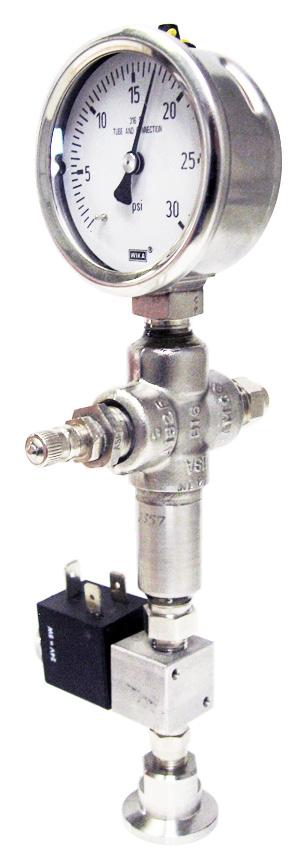
6 3.2 MAKEUP OF A LEAK STANDARD NOTE For available calibrated leak standard configurations, please contact a LACO Technologies sales engineer. Figure 2: Sample Leak Standard INLET PORT OR FILL VALVE The presence and types of inlet ports or fill valves depends upon the requirements and style of the leak standard. Leaks standards that require periodic re-pressurizing are typically supplied with a pressure gauge as part of the leak standard, while leak standards that have an external gas pressure source will not (with some exceptions) have a pressure gauge supplied. Still, other leak standards have factory-sealed fill valves and are designed to be re-pressurized only by the factory PRESSURE GAUGE A pressure gauge may be supplied with the leak standard and is typically supplied with leak standards designed to be re-filled by the customer. For refill instructions, see Section 4.2 REFILLING LEAK ELEMENT LACO Technologies uses four types of leak elements: Micro-tube capillary (a physical orifice) Metal capillary (a physical orifice) Glass permeation (a solid glass membrane) Teflon permeation (a solid Teflon membrane) 4
7 3.2.4 RESERVOIR LACO USER MANUAL - CALIBRATED LEAK STANDARDS All leak standards require a supply of gas; some have a built-in reservoir that contain a supply of gas, while others, having no built-in reservoir, need an independent, regulated supply. These are typically called open-style leak standards OUTLET PORT/CONNECTION Depending upon the leak style, the outlet port of the leak standard is connected to a vacuum system, leak detector, or some other process system. Or, a sniffer probe is placed near or inside the port ISOLATION VALVE An isolation valve at the outlet port may be supplied for convenience in operating the leak standard. Leak standards are available in many types and configurations. Proper use and care of a leak standard is dependent upon its type and style. 5
8 4. BASIC OPERATION 4.1 USING INFORMATION ON LABEL All leak standards include a calibration label bearing important calibration information; where size permits, important physical data regarding the leak standard is also included. In all cases, such information is also found on the calibration certificate. Figure 3: Leak Calibration Label Calibrated Leak Standard Mod No: Sample Leak Ser No: Sample SN Cal No: Cal Date: 1 Jan 2010 Due Date: 1 Jan 2011 Leak Rate 5.00 x 10⁻⁷ (atmcc/sec) 3085 West Directors Row Salt Lake City, UT lacotech.com Temp: 23.0 C Temp Coef: 2.0%/ C Cal Gas: Helium Depl Rate: 15%/year ±8.0% into vac Table 4: Label Information COMPONENT MODEL NUMBER SERIAL NUMBER CALIBRATION NUMBER CALIBRATION TEMPERATURE DESCRIPTION A number that denotes the specifications of the leak standard, including (but not limited to) leak element type, calibration gas, nominal leak rate, number of calibration points, isolation valve type, reservoir type, and connection type. A unique number that identifies the leak standard. A number unique to the calibration of the leak standard and its resulting data, and which identifies that calibration. The temperature at which the calibration was performed. Because temperature affects leak rate (see Temperature Coefficient below), calibration temperature is an important factor. Leak standards should be used within a window of ±10 C of the calibration temperature. 6
9 Table 4: Label Information COMPONENT TEMPERATURE COEFFICIENT DESCRIPTION A constant that allows for a leak rate correction when the leak standard is used at a temperature other than the calibration temperature. The correction is made using the following equation. EQUATION 1: TEMPERATURE COEFFICIENT (CONT D) WHERE: EXAMPLE: QCOR is corrected leak rate (in the same leak rate unit that is on the label), QCAL is leak rate on calibration label, C T is temperature coefficient on label (%/ C), T is ambient temperature at time of leak standard use ( C), TCAL is calibration temperature on label ( C). The label on a leak standard shows a leak rate of 2.00 x 10⁻⁶ atmcc/sec, a calibration temperature of 23.0 C, and a temperature coefficient of 2.0%/ C; the ambient temperature during use of the leak standard is 21.0 C. The corrected leak rate value, according to the above equation, is: CALIBRATION GAS CALIBRATION PRESSURE Gas used in the leak standard and gas used in calibration. Gas pressure needed to achieve the leak rate on the label. For openstyle or refillable leak standards, this pressure must be supplied during use. Do not exceed this pressure, as doing so may damage the leak standard and/or cause personal injury. Pressure in leak standards supplied with a pressure gauge should be monitored and refilled using the supplied gauge as the pressure reference (not a different gauge), as calibration of the leak standard was performed using the supplied gauge. Open-style leak standards not supplied with a pressure gauge should be pressurized using a reference pressure gauge that has been calibrated traceable to national and international standards (e.g. NIST). In many cases, the calibration pressure is denoted in relative terms (e.g. PSIG), meaning atmospheric pressure variations (due to elevation) affect this value. A correction factor to the pressure may need to be applied in these cases. The calibration certificate will note when a correction factor may be needed, and document LF-110, Addendum to Calibration Certificate Leaks with Pressure Gauges is included with the certificate as a reference for making this correction. See Section 10. APPENDIX A: LEAKS WITH PRESSURE GAUGES for details. 7
10 Table 4: Label Information COMPONENT DEPLETION RATE DESCRIPTION This applies to leak standards with reservoirs. Such leak standards have an included gas supply that depletes over time. The leak rate of all leak standards is dependent largely upon the pressure of the gas supply; as that supply diminishes, so does the leak rate. The depletion rate on the label, expressed in terms of percent of leak rate per unit time, allows the user to account for this depletion and estimate a corrected value (as well as determine an adequate recalibration interval; see below). The correction is performed using the following equation. EQUATION 2: WHERE: QCOR is corrected leak rate (in the same leak rate unit as on the label), QCAL is leak rate on calibration label, DR is depletion rate on label (usually %/year), T is approximate time in months since calibration. EXAMPLE: The label on a leak standard shows a leak rate of 2.00 x 10⁻⁵ atmcc/sec, with a depletion rate of 5.0%/year and a calibration date of Jan. 1, If the current date is July 1, 2004, the corrected leak rate of the leak standard is Depletion rate is an important factor in determining recalibration intervals for leak standards. In general, the higher the depletion rate, the lower the recalibration interval should be. Many leak standards are equipped with an isolation valve; while storing such a leak standard with the isolation valve closed may reduce the depletion rate in some cases, this technique should not be considered an alternative to recalibration, or justification to disregard depletion rate. Where depletion rate is a significant issue, a special valve, called a zero-volume valve, can be supplied with new leak standards. When kept closed during non-use, a zerovolume valve effectively reduces the depletion rate to zero. 8
11 Table 4: Label Information COMPONENT LEAK RATE DESCRIPTION The measured value of the leak rate of the leak standard, as determined by calibration. Leak rate values are also expressed in terms of the outlet pressure conditions, which are typically vacuum or atmosphere. APPENDIX B: LEAKS FLOWING TO ATMOSPHERE describes corrections that may be required for leaks flowing to atmospheric pressure. The table below includes conversions between different leak rate units. Table 5: Leak Rate Conversion CONVERT FROM MULTIPLY BY CONVERT TO atm-cc/sec mbar-liter/sec atm-cc/sec 0.76 torr-liter/sec torr-liter/sec 1.33 mbar-liter/sec Pa-M3/sec 9.87 atm-cc/sec To convert from volumetric flow units to mass flow units use the following Equation 3. EQUATION 3: WHERE: EXAMPLE: QMASS is the mass leak rate in grams/year, QVOL is the volumetric leak rate in atmcc/sec, MW is the molecular weight of the gas, grams/mole, T is the absolute temperature, K (typically 298), is the ideal gas constant 31,500 converts seconds to years and cc to liters. A leak standard of R134a refrigerant has a volumetric leak rate of 1.00 x 10⁻⁵ atmcc/sec. It s molecular rate is grams/mole. Using equation 3 above, the mass leak rate is 1.31 grams per year, or, dividing by the molecular weight, MW, the molar leak rate is moles per year at 298 K. 9
12 Table 4: Label Information COMPONENT UNCERTAINTY DESCRIPTION Expressed as a percent of the leak rate. All measurements, including leak rate measurements, have a degree of uncertainty associated with them. This number defines the window, centered at the calibrated leak rate value, in which the true leak rate likely falls. For example, if a leak standard has a calibrated leak rate of 2.00 x 10⁻⁷ cc/sec and its uncertainty is ±10%, the true leak rate is likely between 1.80 x 10⁻⁷ and 2.20 x 10⁻⁷ cc/sec. NOTE The uncertainty is an expression of the calibration uncertainty, and is a function of the calibration process, not a physical property of the calibrated leak standard. All LACO leak standards are backed our lifetime product warranty and include a NIST traceable, A2LA accredited calibration certificates to ISO and ANSI Z standards. For more information, see section Section 6. CALIBRATION OF LEAKS. 4.2 REFILLING Leak standards with a built-in pressure gauge may require being repressurized periodically (due to gas depletion; see above). Re-pressurization is recommended when the gas pressure shown on the gauge is more than 2% change from the calibration pressure (as indicated on the calibration label and certificate). Leak standards that do not have a pressure gauge should not be refilled; rather, it should be returned to the factory for recalibration. If re-pressurization is necessary, the following steps should be carefully followed to avoid damaging the leak standard, altering the calibration, or causing personal injury. Only clean, dry gas of 99.99% purity or better should be used. Ensure that all valves, hoses, and piping are clean and particle free before using them to refill leak standards. 10
13 4.2.1 REFILLING WITH A VACUUM PUMP Figure 4: Refilling a Leak Standard with a Vacuum Pump Leak Standard 1. After ensuring that the fill valve is closed, remove the protective cap from the valve. 2. Connect the fill valve to a configuration similar to the diagram above. 3. With the vent valve and gas supply valve closed, start the vacuum pump and open the vacuum valve; allow several seconds to adequately evacuate all air from the system. Vacuums below 1 torr are sufficient. 4. Close the vacuum valve. 5. Open the fill valve on the leak standard. 6. Open the gas supply valve and slowly increase pressure using the regulator until the leak standard pressure gauge indicates the desired pressure. Let sit for 1-2 minutes to minimize thermal effects. Adjust regulator if necessary. 7. Tightly close fill valve and close gas supply valve. 8. Slowly open vent valve to release pressure in the system 9. Remove the leak standard and replace protective cap on fill valve. 11
14 4.2.2 REFILLING WITHOUT A VACUUM PUMP Figure 5: Refilling a Leak Standard without a Vacuum Pump Leak Standard NOTE: Use this procedure only if a vacuum pump is not available 1. After ensuring that the fill valve is closed, remove the protective cap from the valve. 2. Loosely connect the fill valve to a configuration similar to the diagram above. 3. With the fill valve closed, open the gas supply valve and purge the connecting tube of air by allowing the calibration gas (at low pressure) to flow through the line and the loose connection for several seconds. 4. Tighten the fill valve connection. 5. Adjust the regulator to the approximate pressure required in the leak standard. 6. Open the fill valve and wait 1-2 minutes to minimize thermal effects. 7. Adjust pressure as needed. 8. Close fill valve. 9. Close regulator and remove leak standard. 12


15 4.3 USE IN VACUUM AND SNIFFING APPLICATIONS USE APPROPRIATE CONNECTIONS Leak standards that leak into vacuum should be connected to the vacuum system with an appropriate connection. For example, flange connections should use a clean, properly sized and centered oring, with a proper clamp, and tapered thread connections should be sealed with Teflon tape or other thread-sealing substance LEAK STANDARD EXPOSURE Avoid connecting leak standards to vacuum systems where an oil-sealed rotary vane pump will be continually pumping on, or exposed to, the leak standard. Over time oil may backstream from the pump to the leak standard and contaminate it with oil. A leak standard that has oil at its outlet port is likely contaminated and should be returned to the factory for recalibration and/or repair USING SNIFFER PROBES Leak standards that leak into air (atmosphere) can be subject to many errors when used to calibrate a sniffer leak detector. An appropriate sized probe should be used to minimize errors. Readings can be affected depending on sniffer probe location, or if a sniffer probe is used with a leak standard with vacuum connections. 4.4 DUAL RESERVOIR LEAK STANDARDS Some halogen leak standards use a dual-reservoir to contain refrigerant in both gas and liquid form. These leak standards require special instructions and care. Figure 6: Sample Halogen Leak Standard 13
16 Pressure may be adjusted to obtain any leak rate that is within the range specified on the calibration curve supplied with the calibration certificate (and/or attached to the leak standard). Pressure, as indicated on the gauge, must match the pressure value corresponding to the desired leak rate from the calibration curve. To increase pressure: insure that the leak standard is upright and sitting flat; slowly open the Increase valve while monitoring the pressure gauge; when the desired pressure is reached, close the valve. Do not exceed the maximum pressure of the gauge, as this may damage the gauge. To decrease pressure: slowly open the decrease valve; when the desired pressure is reached, close the valve. Do not freeze; if possible, store and use at room temperature. Do not expose to temperatures greater than 120 F, as explosion may occur. Do not attempt to recharge the primary reservoir with refrigerant. If recharging is necessary (as indicated by the inability to reach the highest calibration pressure), return it to the factory. Take special care not to touch the leak port, as this may lead to plugging of the capillary leak element. 4.5 OPEN STYLE HELIUM LEAK STANDARDS Open style leak standards that use helium as the tracer gas must have helium properly supplied to the inlet of the leak standard in order for the leak to perform properly. For example, if the leak standard was calibrated with 100% helium at a specified pressure, then it is important that any air that is in the helium supply line is properly removed, otherwise the helium supplied to the leak element of the leak standard will be diluted with the existing air in the supply line even when the correct helium pressure is supplied. In general, the same principles that apply to filling a helium reservoir leak standard as outlined in section apply to supplying helium to an open style leak standard. Use the following guidelines when supplying helium to the inlet of an open style helium leak standard. 1. Always ensure helium supply lines have been cleaned and purged and free from any moisture, oils, or particle contamination. In addition to having clean supply lines it is desirable to also provide particulate filtration as well. 14
17 2. If the leak standard is to be mounted to the customer part to simulate a leak, ensure that the leak standard is protected from damage (from abusive or careless handling) or contamination (particles or liquids). In these applications the helium supplied to the leak is intended to be the same as it is supplied to the actual part under test conditions. It is important that the leak standard see the same source of helium using the same filling protocol as is used during a normal leak test on the part. This will ensure that the leak standard responds to the system in the same way that an actual leak on the part will respond. 3. When connecting the leak standard to the helium source for the first time use one of the following methods to ensure air is removed from the supply lines. See section for additional details. a. Evacuate the line between the helium source isolation valve and the leak standard to an absolute pressure no higher than 1 torr (1.3 mbar) prior to supplying the helium to the leak standard. b. If no vacuum pump is available, use helium to purge the line between the helium source isolation valve and the leak standard by loosening the connection to the leak standard and allowing helium to flow through the line for a few seconds. When doing this take care not to contaminate the test area with helium as this could potential impact leak rate readings. 4. If the leak standard is to be connected to an intermittent supply of helium, controlled by an isolation valve, then it is recommended that the helium supply line be configured with a three-way valve and vacuum pump. 5. When replacing the helium supply, such as when changing out a gas bottle, ensure that the supply lines are purged or evacuated as outlined in section 3 above. 15
18 5. MAINTENANCE LACO USER MANUAL - CALIBRATED LEAK STANDARDS Store leak standards at moderate temperatures; do not expose leak standards to temperatures less than -20 C or greater than 150 C, or store them for long periods of time at extreme temperatures. Store leak standards in a clean, dry area; protect from dust, moisture, oil, and other potential contaminants. Place cap or other clean covering over leak port during storage. Protective carrying/storage cases are available from factory. Leak standards with a permeation leak element should be stored with the isolation valve (if equipped with one) open. Do not attempt to clean a potentially contaminated leak element; if operability is in question, return the item to vendor for repair evaluation. Ensure that flanges, threads, and other connecting surfaces are protected from scratches, dings, etc. 6. CALIBRATION OF LEAKS All LACO leak standards are backed our lifetime product warranty and include a NIST traceable, A2LA accredited calibration certificates to ISO and ANSI Z standards. LACO uses several methods to measure and calibrate leak standards. The calibration method selected for any given leak depends on the calibration gas, range of the leak standard, the outlet conditions of the leak standard (vacuum or atmospheric pressure), and the desired uncertainty. LACO uses two types of calibration methods: primary, and secondary or transfer standard methods. The primary calibration methods incorporate measurements of basic physical properties such as time, volume, and pressure. These methods measure the leak rate of the leak standard under test by measuring the pressure or volume change induced by gas flowing into a known system. The secondary calibration methods use a calibration transfer standard that has been calibrated on a primary system or at a primary standards laboratory. The leak rate of the leak standard under test is measured and compared to that of the known reference standard. The actual calibration method used on a particular leak standard is referenced by calling out the calibration procedure on the certificate of calibration. 16
19 7. SHIPPING INSTRUCTIONS Leak standards equipped with a pressurized gas reservoir may be subject to special shipping requirements. Consult local and federal requirements to insure that you are in compliance when shipping and transporting leak standards. When returning a leak standard to LACO for repair or calibration contact our sales team to obtain shipping information and a Return Materials Authorization (RMA) number. Always package the leak standard in a sealed package to protect it from dust and moisture. 8. WARRANTY INFORMATION LACO calibrated leak standards are warranted to be free from defects over the lifetime of the standard. Pressure gauges are warranted for one year. The warranty does not cover damage to leak standards due to mishandling or improper use. The warranty is only valid while the leak standard is calibrated at LACO Technologies, Inc. on the recommended calibration interval, typically yearly. If a warranty request is made, LACO Technologies, at its own discretion, will repair or replace the leak standard, including labor and materials. Leaks that are found to be nonfunctional at time of calibration shall be repaired free of charge. The customer, however, is responsible for the calibration cost. The customer is responsible for any and all shipping charges. 17
20 9. APPENDIX A: LEAKS WITH PRESSURE GAUGES This appendix applies to calibrated leaks supplied with reservoir pressure gauges and for calibrated leaks without reservoirs where the customer supplies a pressure gauge. The leak rate of gas leak standards is related to the absolute gas pressure applied to the leak element. A typical bourdon tube pressure gauge supplied on calibrated leaks measures gauge or relative pressure, which changes with elevation. Use the following formulas to convert the pressure reported on the calibration certificate to the correct pressure at your elevation (barometric pressure). 9.1 CALCULATE ABSOLUTE PRESSURE FROM CALIBRATION CERTIFICATE EQUATION 4: WHERE: P(absolute, atm)= P(atmospheric) + P(leak)/14.7 P(atmospheric) = atmospheric (barometric) pressure at calibration reported on calibration certificate in atmospheres. P(leak) = gas pressure reported on the calibration certificate in psig. 9.2 CALCULATE THE GAUGE PRESSURE FOR LOCAL ATMOSPHERIC (BAROMETRIC) PRESSURE EQUATION 5: P(leak, psig) = (P(absolute) P(atmospheric)) x 14.7 WHERE: P(absolute) = pressure calculated from Equation 4 in atmospheres. P(atmospheric) = local atmospheric pressure measured from a barometer or Table 6 below, in atmospheres. Table 6: Elevation vs. Atmospheric Pressure ELEVATION (FEET) AVERAGE ATMOSPHERIC PRESSURE (ATM) 0 (sea level) , , ,
21 Table 6: Elevation vs. Atmospheric Pressure ELEVATION (FEET) AVERAGE ATMOSPHERIC PRESSURE (ATM) 4, , , , , , , APPENDIX B: LEAKS FLOWING TO ATMOSPHERE This appendix applies to calibrated leaks that flow to atmospheric pressure where the atmospheric pressure during the calibration of the leak may be different compared to the atmospheric pressure during the use of the leak. The leak rate of gas leak standards is related to the absolute gas pressure applied to the leak element and the atmospheric pressure at the leak outlet. A correction must be made to leaks used at a different atmospheric pressure from the calibration atmospheric pressure. The atmospheric pressure can generally be estimated by knowing the elevation. Use the following formulas to correct the leak rate for your atmospheric conditions CONVERT PRESSURE TO ABSOLUTE PRESSURE EQUATION 6: WHERE: P 1 = P(atmospheric) + P(leak)/14.7 P 1 = absolute pressure applied to the leak in atmospheres. P(atmospheric) = atmospheric (barometric) pressure at calibration reported on calibration certificate in atmospheres. P(leak) = gas pressure reported on the calibration certificate in psig 19
22 10.2 CALCULATE THE LEAK CONSTANT, K EQUATION 7: WHERE: Q = K ( P 1 2 P 2 2 ) for viscous flow leaks, or K = Q / ( P 1 2 P 2 2 ) Q (atmcc/sec) = leak rate of the gas under calibration conditions P 1 (atm) = absolute pressure applied to the upstream side of the leak calibration certificate in atmospheres (see Equation 6 above). P 2 (atm) = atmospheric pressure reported on the calibration certificate. K = leak constant 10.3 CALCULATE THE CORRECTED LEAK RATE Using Equations 6 and 7 above, the leak constant K, and Table 7 below, calculate the corrected leak rate. Calculate P 1 from equation 1 above using atmospheric pressure from Table 6 below. Use atmospheric pressure from Table 6 for P 2. Table 7: Leak Rate Calculation STEP CALIBRATION CERTIFICATE READS: CURRENT CONDITIONS: STEP 1 STEP 2 DESCRIPTION Leak Rate: 5.0 x 10⁻³ atmcc/sec Pressure: 20 psig Air Barometric Pressure: 0.85 atmospheres Barometric Pressure: 1 atm (sea level) P 1 = (0.85) + 20/14.7 = 2.21 atm At current conditions: P 1 = (1.0) + 20/14.7 = 2.36 atm STEP 3 Q (corrected) = 1.20 x 10⁻³ ( ) = 5.49 x 10 3 atmcc/sec 20
23 21
24 CONTACT US PHONE/FAX Toll Free: Phone: Fax: ADDRESS LACO Technologies, Inc West Directors Row Salt Lake City, UT WEB SMT revc1
GPP model GPPT model GPC model CLP model
 CHOOSING A CALIBRATOR FOR HELIUM LEAK DETECTORS Unique Vacuum Solutions deals with four models of Calibrated Leak Standards for calibrating Helium Leak Detectors and Leak Testing Systems so that one is
VIC offers a variety of Calibrated Gas Leaks
 CALIBRATED GAS LEAKS VIC offers a high quality line of calibrated gas leaks traceable to National Institute of Standards Technology (NIST). Calibrated gas leaks are used to provide a controlled delivery
Finding Leak Testing Success Through Calibration and Validation. Paul Chamberlain President, CEO
 Finding Leak Testing Success Through Calibration and Validation Paul Chamberlain President, CEO 2 Overview Confidence in Your Leak Test Results Sources of Uncertainty Pressure decay leak testing Helium
VACUUM CHAMBER MANUAL
 VACUUM CHAMBER MANUAL INDUSTRIAL VACUUM CHAMBERS CONTACT US PHONE/FAX Toll Free: 800.465.1004 Phone: 801.486.1004 Fax: 801.486.1007 ADDRESS LACO Technologies, Inc. 3085 West Directors Row Salt Lake City,
DPC-30 DPC-100. Reference Manual
 DPC-30 DPC-100 Reference Manual 1. Introduction 1.1 Description The Martel DPC Digital Pneumatic Calibrator improves upon traditional dial gauge pneumatic calibrators. The Martel DPC improves accuracy,
INSTRUCTIONS FOR MODELS SG3897 AND SG3898 CROSS PURGE ASSEMBLIES
 INSTRUCTIONS FOR MODELS SG3897 AND SG3898 CROSS PURGE ASSEMBLIES THIS BOOKLET CONTAINS PROPRIETARY INFORMATION OF ADVANCED SPECIALTY GAS EQUIPMENT CORP. AND IS PROVIDED TO THE PURCHASER SOLELY FOR USE
GILMONT ACCUCAL FLOWMETERS
 OPERATING MANUAL GILMONT ACCUCAL FLOWMETERS 28W092 Commercial Ave. Barrington, IL U.S.A. 60010-2392 (847) 381-4888 (847) 381-7053 (Fax) 800-962-7142 www.barnant.com e-mail: barnant@barnant.com A-1299-0766
Section 3- Repair and Calibration Procedures
 Section 3- Repair and Calibration Procedures 1. Refrigerant Removal Procedures 2. Scale/PC Board Recalibration Procedure 3. PC Board Configuration Procedure of AR400 4. Scale Tare Procedure 5. Gauge Calibration
Generating Calibration Gas Standards
 Technical Note 1001 Metronics Inc. Generating Calibration Gas Standards with Dynacal Permeation Devices Permeation devices provide an excellent method of producing known gas concentrations in the PPM and
OPERATION MANUAL NTF-15
 OPERATION MANUAL NTF-15 Nitrogen Tire Filling Valve Stem Caps (Qty=200) Order P/N 436075 RTI Technologies, Inc 10 Innovation Drive York, PA 17402 800-468-2321 www.rtitech.com 035-81235-00 (Rev B) TABLE
OPERATION MANUAL NTF-60 Plus
 OPERATION MANUAL NTF-60 Plus Nitrogen Tire Filling Valve Stem Caps (Qty=200) Order P/N 436075 RTI Technologies, Inc 10 Innovation Drive York, PA 17402 800-468-2321 www.rtitech.com 035-81264-00 (Rev A)
METHOD 25A - DETERMINATION OF TOTAL GASEOUS ORGANIC CONCENTRATION USING A FLAME IONIZATION ANALYZER
 1250 METHOD 25A - DETERMINATION OF TOTAL GASEOUS ORGANIC CONCENTRATION USING A FLAME IONIZATION ANALYZER 1.0 Scope and Application. 1.1 Analytes. Analyte CAS No. Sensitivity Total Organic Compounds N/A
Detector Carrier Gas Comments Detector anode purge or reference gas. Electron Capture Nitrogen Maximum sensitivity Nitrogen Argon/Methane
 Gas requirements Gases for packed columns The carrier gas you use depends upon the type of detector and the performance requirements. Table 520-1 lists gas recommendations for packed column use. In general,
LOW PRESSURE EFFUSION OF GASES revised by Igor Bolotin 03/05/12
 LOW PRESSURE EFFUSION OF GASES revised by Igor Bolotin 03/05/ This experiment will introduce you to the kinetic properties of low-pressure gases. You will make observations on the rates with which selected
Operation Manual - PN A MENSOR MODEL 73 SHOP AIR BOOSTER
 Operation Manual - PN 0017946001 A MENSOR MODEL 73 SHOP AIR BOOSTER Mensor Model 73 Shop Air Booster System (750 psi Version) April 23, 2012 Trademarks / Copyright Mensor is a registered trademark of Mensor
MAINTENANCE & ASSEMBLY INSTRUCTIONS FUSIBLE LINK. Inline Thermal Check Valve
 MAINTENANCE & ASSEMBLY INSTRUCTIONS IOM-FL 12-16 ISO Registered Company FUSIBLE LINK Inline Thermal Check Valve MODEL FL-200 REFERENCE DATA: FL-200 Series Assembly Drawing No. A88-60200-00. INSTALLATION:
CORESTA RECOMMENDED METHOD N 6
 CORESTA RECOMMENDED METHOD N 6 DETERMINATION OF VENTILATION DEFINITIONS AND MEASUREMENT PRINCIPLES (2015 Revision September 2016) 1. SCOPE This CORESTA Recommended Method specifies a method for the determination
Mooney * Noise Controller Installation, Operation, and Maintenance Manual
 GE Oil & Gas Mooney * Noise Controller Installation, Operation, and Maintenance Manual imagination at work Scope This manual provides instructions for installation, operation and maintenance of the Mooney
RDK-408D2 Cold Head. Technical Manual. SHI-APD Cryogenics Inc Vultee Street Allentown, PA U.S.A. Revision A: September 2005
 RDK-408D2 Cold Head Technical Manual SHI-APD Cryogenics Inc. 1833 Vultee Street Allentown, PA 18103-4783 U.S.A. Revision A: September 2005 (Reference SHI Manual: December 18, 2003 266404A CD32ZZ-160A)
INSTALLATION & MAINTENANCE INSTRUCTIONS
 DESCRIPTION / IDENTIFICATION The QBX series valve uses Proportion-Air closed loop technology for Pressure control. It gives an output pressure proportional to an electrical command signal input. The QB1X
Inert Air (N2) Systems Manual
 Systems Manual") INSTRUCTION MANUAL Inert Air (N2) Systems Manual N2-MANUAL 2.10 READ AND UNDERSTAND THIS MANUAL PRIOR TO OPERATING OR SERVICING THIS PRODUCT. GENERAL INFORMATION Positive pressure nitrogen gas pressurizing
INSTRUCTION MANUAL Inert Air (N2) Systems Manual N2-MANUAL 2.10 READ AND UNDERSTAND THIS MANUAL PRIOR TO OPERATING OR SERVICING THIS PRODUCT. GENERAL INFORMATION Positive pressure nitrogen gas pressurizing
FUGITIVE EMISSIONS EXPERIMENTAL MEASUREMENTS AND EQUIVALENCY
 FUGITIVE EMISSIONS EXPERIMENTAL MEASUREMENTS AND EQUIVALENCY ABSTRACT Jay Abrahimzadeh Joe Steinke Control Components Inc. Fugitive Emissions requirements, compliance, and use have gained momentum in the
METHOD 21 - DETERMINATION OF VOLATILE ORGANIC COMPOUND LEAKS. 1.2 Scope. This method is applicable for the
 1151 METHOD 21 - DETERMINATION OF VOLATILE ORGANIC COMPOUND LEAKS 1.0 Scope and Application. 1.1 Analytes. Analyte Volatile Organic Compounds (VOC) CAS No. No CAS number assigned 1.2 Scope. This method
LRS(H)4 USER MANUAL. Read the complete manual before installing and using the regulator.
4 USER MANUAL. Read the complete manual before installing and using the regulator.") LRS(H)4 USER MANUAL Read the complete manual before installing and using the regulator. WARNING INCORRECT OR IMPROPER USE OF THIS PRODUCT CAN CAUSE SERIOUS PERSONAL INJURY AND PROPERTY DAMAGE. Due to the
LRS(H)4 USER MANUAL Read the complete manual before installing and using the regulator. WARNING INCORRECT OR IMPROPER USE OF THIS PRODUCT CAN CAUSE SERIOUS PERSONAL INJURY AND PROPERTY DAMAGE. Due to the
RS(H)10,15 USER MANUAL. Read the complete manual before installing and using the regulator.
10,15 USER MANUAL. Read the complete manual before installing and using the regulator.") RS(H)10,15 USER MANUAL Read the complete manual before installing and using the regulator. WARNING INCORRECT OR IMPROPER USE OF THIS PRODUCT CAN CAUSE SERIOUS PERSONAL INJURY AND PROPERTY DAMAGE. Due to
RS(H)10,15 USER MANUAL Read the complete manual before installing and using the regulator. WARNING INCORRECT OR IMPROPER USE OF THIS PRODUCT CAN CAUSE SERIOUS PERSONAL INJURY AND PROPERTY DAMAGE. Due to
Instruction Manual. CG16K Barometrically Compensated Capsule Dial Gauge. CG16K Capsule Dial Gauge, 0 to 25 mbar
 Instruction Manual D356-10-880 Issue G Original CG16K Barometrically Compensated Capsule Dial Gauge Description CG16K Capsule Dial Gauge, 0 to 1040 mbar CG16K Capsule Dial Gauge, 0 to 125 mbar CG16K Capsule
NB/NBR NITROGEN BOOSTER FOR AVIATION SERVICE
 NB/NBR NITROGEN BOOSTER FOR AVIATION SERVICE INSTALLATION, OPERATION & MAINTENANCE MANUAL INTERFACE DEVICES, INC. 230 Depot Road, Milford, CT 06460 Ph: (203) 878-4648, Fx: (203) 882-0885, E-mail: info@interfacedevices.com
Yoke Block Instruction Manual
 Yoke Block Instruction Manual ! WARNING IMPORTANT: READ MANUAL COMPLETELY BEFORE OPERATING THIS DEVICE This manual contains instructions on periodically required checks to be performed by the user. These
Lab 3 Introduction to Quantitative Analysis: Pumps and Measurements of Flow
 Georgia Institute of Technology School of Earth and Atmospheric Sciences EAS 4641, Spring 2008 Lab 3 Introduction to Quantitative Analysis: Pumps and Measurements of Flow Purpose of Lab 3: 1) To gain a
G96 Series BASOTROL Dual Operator Valve
 Installation Instructions 9. Issue Date February 22, 2013 G96 Series BASOTROL Dual Operator Valve Applications The G96 valves are combination, dual operator, automatic valves available with or without
HEAT EXCHANGE AND TRANSFER, INC. 500 Superior Street Carnegie, PA (412) Fax: (412)
 Fax: (412)") SECTION Bypass Oil Sampling Station (B.O.S.S 1000) GENERAL.......................... SAFETY........................... Hazards............................... Personal Protective Equipment........... PRODUCT
SECTION Bypass Oil Sampling Station (B.O.S.S 1000) GENERAL.......................... SAFETY........................... Hazards............................... Personal Protective Equipment........... PRODUCT
36E DSI, HSI & Proven Pilot Two-Stage Combination Gas Valve INSTALLATION INSTRUCTIONS
 INLET PRESS TAP WTE-RODGERS 36E96-314 DSI, HSI & Proven Pilot Two-Stage Combination Gas Valve INSTALLATION INSTRUCTIONS Operator: Save these instructions for future use! FAILURE TO READ AND FOLLOW ALL
INSTRUCTIONS FOR MODEL SG6500 GAS HEATERS
 INSTRUCTIONS FOR MODEL SG6500 GAS HEATERS THIS BOOKLET CONTAINS PROPRIETARY INFORMATION OF ADVANCED SPECIALTY GAS EQUIPMENT CORP. AND IS PROVIDED TO THE PURCHASER SOLELY FOR USE IN CONJUNCTION WITH MODEL
Operating Manual. Model 25200B/25202B Refrigerant Recovery Unit. (Not for use in automotive R-134a applications)
") Operating Manual Model 25200B/25202B Refrigerant Recovery Unit (Not for use in automotive R-134a applications) ROBINAIR Refrigerant Recovery Unit Model: 25200B /25202B Series Type of Equipment: Recovery
Operating Manual Model 25200B/25202B Refrigerant Recovery Unit (Not for use in automotive R-134a applications) ROBINAIR Refrigerant Recovery Unit Model: 25200B /25202B Series Type of Equipment: Recovery
PRS(TC)4,8 USER MANUAL. Read the complete manual before installing and using the regulator.
4,8 USER MANUAL. Read the complete manual before installing and using the regulator.") PRS(TC)4,8 USER MANUAL Read the complete manual before installing and using the regulator. WARNING INCORRECT OR IMPROPER USE OF THIS PRODUCT CAN CAUSE SERIOUS PERSONAL INJURY AND PROPERTY DAMAGE. Due to
PRS(TC)4,8 USER MANUAL Read the complete manual before installing and using the regulator. WARNING INCORRECT OR IMPROPER USE OF THIS PRODUCT CAN CAUSE SERIOUS PERSONAL INJURY AND PROPERTY DAMAGE. Due to
SUBSTATION MAINTENANCE ELECTRICAL OPERATING PROCEDURE
 Page 1 of 6 A. PURPOSE AND SCOPE This procedure establishes safe working practices for handling sulfur hexafluoride (SF 6 ) gas and release minimization practices. This document also specifies methods
LOW PRESSURE EFFUSION OF GASES adapted by Luke Hanley and Mike Trenary
 ADH 1/7/014 LOW PRESSURE EFFUSION OF GASES adapted by Luke Hanley and Mike Trenary This experiment will introduce you to the kinetic properties of low-pressure gases. You will make observations on the
INSTALLATION, OPERATION AND MAINTENANCE MANUAL. Model Sanitary Vent SECTION I
 INSTALLATION, OPERATION AND MAINTENANCE MANUAL Model 1100 Sanitary Vent IOM-1100 03-17 ISO Registered Company SECTION I I. DESCRIPTION AND SCOPE The Model 1100 is a stainless steel sanitary vent designed
Pressure Regulators. Operating Instructions. Instrumentation
 Pressure Regulators Operating Instructions FAILURE OR IMPROPER SELECTION OR IMPROPER USE OF THIS PRODUCT CAN CAUSE DEATH, PERSONAL INJURY AND PROPERTY DAMAGE. This document and other information from the
BGA244 Binary Gas Analyzer
 Quick Start Guide Revision 1.0 Certification Warranty Service certifies that this product met its published specification at the time of shipment. This product is warranted against defects in materials
Purge Star & Ring Purge Systems
 March 2013 Operator s Manual Purge Star & Ring Purge Systems Additional instruction for Purge Star Single Hose, Purge Star Double (bypass) Hose and Ring Purge with bypass hose and gas dump valve feature.
Full Internal Relief Valves Instruction Manual
 Full Internal Relief Valves Instruction Manual MEV200FIR & MEV300FIR Application: Designed for use in mobile LPG & NH 3 containers as a primary pressure relief valve for bobtail and transport trailer installations.
CO 2. (R744) Service Station Presentation. Contents. Goals Basic functions Specification Recovery R477 Vacuum Charge Safety Other features Prototype
 Service Station Presentation. Contents. Goals Basic functions Specification Recovery R477 Vacuum Charge Safety Other features Prototype") (R744) Service Station Presentation Contents Goals Basic functions Specification Recovery R477 Vacuum Charge Safety Other features Prototype Page 1 (R744) Service Station Goals Usability Full automatic
(R744) Service Station Presentation Contents Goals Basic functions Specification Recovery R477 Vacuum Charge Safety Other features Prototype Page 1 (R744) Service Station Goals Usability Full automatic
OXY Integral. INTERCON ENTERPRISES INC Tel: Fax: Internet:
 OXY Integral INTERCON ENTERPRISES INC Tel: 800 665 6655 Fax: 604 946 5340 E-Mail: sales@intercononline.com Internet: www.intercononline.com Manual Integral 2006 1 INDEX 2-3 PREFACE 4 INTRODUCTION 5 Principle
The Helium Leak Detector
 The Helium Leak Detector Helium Leak Detector Main Components The main components of a helium leak detector are: 1. The analyzed, which enables to separate the tracer gas from other gases inside leak detector.
HYDROVEX TTT Membrane Flow Regulator
 HYDROVEX TTT Membrane Flow Regulator INSTALLATION, OPERATION AND MAINTENANCE MANUAL PROJECT EQUIPMENT LOCATION EQUIPMENT DESCRIPTION HYDROVEX TTT REFERENCE N OF THE SUPPLIER MODEL N SERIAL N DATE OF FABRICATION
Technical Information
 Technical Information Installation, Operation, Installation, Operation and Maintenance and Maintenance Manual Manual Balston Model 75700-K728 Nitrogen Generator Figure 1-75700-K728 Overall Dimensions These
LRS(H)4 Pressure-Reducing Regulator User Manual
4 Pressure-Reducing Regulator User Manual") LRS(H)4 Pressure-Reducing Regulator User Manual Read the complete manual before installing and using the regulator. 2 Safe Product Selection When selecting a product, the total system design must be considered
LRS(H)4 Pressure-Reducing Regulator User Manual Read the complete manual before installing and using the regulator. 2 Safe Product Selection When selecting a product, the total system design must be considered
DTG - LCD Digital Temperature Gauge USER MANUAL
 DTG - LCD USER MANUAL Page 1 of 7 USERS GUIDE page 1. Description 3 2. Function 3 3. Safety Instruction 3 3.1. Safety Conventions 3 3.2. Proper Use 3 4. Installation 4 4.1. Unpacking 4 4.2. Storage 4 4.3.
Applications of a Magnetic Sector Process Mass Spectrometer to the Analysis of Variable Vacuum Samples
 Applications of a Magnetic Sector Process Mass Spectrometer to the Analysis of Variable Vacuum Samples Outline of Presentation Introduction Process Gas Analysis Magnetic Sector Mass Spectrometer Standard
PAPR Flow Tester. instructions. part no WARNING
 PAPR Flow Tester part no. 488903 instructions WARNING This manual, including warnings and cautions inside, must be carefully read and followed by all persons who use or maintain the product, including
SAFETY MANUAL FOR FLAMMABLE PRODUCT TRANSFER
 SAFETY MANUAL FOR FLAMMABLE PRODUCT TRANSFER SUPPLIMENT TO eom IMPORTANT READ THIS MANUAL BEFORE PRODUCT INSTALLATION, OPERATION, INSPECTION & MAINTENANCE Tougher and more rigid guidelines are being established
VB-7213 Series. Application. Features. Applicable Literature. 1/2" to 2" Screwed NPT Stem Up Open, Two-Way Valves General Instructions
 VB-7213 Series 1/2" to 2" Screwed NPT Stem Up Open, Two-Way Valves General Instructions Application VB-7213 series single seat, stem up open, two-way valves control water from 20 to 281 F (-7 to 138 C)
453 Series Steam Heated Vaporizing Regulator
 ADI 0453A Certified ISO 9001:2000 453 Series Steam Heated Vaporizing Regulator INSTALLATION AND OPERATION INSTRUCTIONS Before Installing or Operating, Read and Comply with These Instructions Controls Corporation
Bulletin TCR-104 & 109 Filling and adding to the Glycol pressure system
 Bulletin 061013 TCR-104 & 109 Filling and adding to the Glycol pressure system 1. Glycol System and air On this model the glycol system is a closed system, the glycol is not exposed to the air. No external
TESCOM 50-4X Series Safety, Installation & Start-Up Procedures
 Operations & Service Manual TESCOM 50-4X Series Safety, Installation & Start-Up Procedures Do not attempt to select, install, use or maintain this product until you have read and fully understood this
GA / 3.02 TL 4 TL 6. Cat. No Calibrated leaks GA / 3.02 TL 4 TL 6. Cat. No
 O P E R A T I N G I N S T R U C T I O N S GA 10.18 / 3.02 TL 4 TL 6 Cat. No. 155 65 155 66 Calibrated leaks O P E R A T I N G I N S T R U C T I O N S GA 10.18 / 3.02 TL 4 TL 6 Cat. No. 155 65 155 66 Calibrated
RD(H)20/25 Pressure-Reducing Regulator User Manual
20/25 Pressure-Reducing Regulator User Manual") RD(H)20/25 Pressure-Reducing Regulator User Manual Read the complete manual before installing and using the regulator. 2 Safe Product Selection When selecting a product, the total system design must be
RD(H)20/25 Pressure-Reducing Regulator User Manual Read the complete manual before installing and using the regulator. 2 Safe Product Selection When selecting a product, the total system design must be
Introductory Lab: Vacuum Methods
 Introductory Lab: Vacuum Methods Experiments in Modern Physics (P451) In this lab you will become familiar with the various components of the lab vacuum system. There are many books on this topic one of
Instruction Manual 742 5/1/2009. Eclipse Ratio Regulators ES Series Version 1
 Instruction Manual 742 5/1/2009 Eclipse Ratio Regulators ES Series Version 1 Copyright Copyright 1997 by Eclipse, Inc. All rights reserved worldwide. This publication is protected by federal regulation
VB-7263 Series. Application. Features. Applicable Literature
 TAC 1354 Clifford Avenue P. O. Box 2940 Loves Park, IL 61132-2940 www.tac.com VB-7263 Series 1/2" to 2" Screwed NPT Stainless Steel Trim with Teflon Disc Stem Up Closed, Two-Way Valves General Instructions
EASTERN ENERGY SERVICES PTE LTD. 60 Kaki Bukit Place #02-19 Eunos Tech Park Singapore, SG Singapore Telephone: Fax:
 2 Table Of Contents 1. Introduction 3 2. About this Manual 3 3. Contacting YZ Systems 3 4. Vessel Components 4 5. Specifications 5 6. Application 6 7. Theory of Operation 7 8. DuraSite Installation & Use
Table of Contents. Operating Instructions. Resource v.2 Conserving Regulator
 Operating Instructions Table of Contents Resource v.2 Conserving Regulator Safety Information Device Precautions Introduction Product Features Product Specifications Feature Illustrations Set Up Usage
Sterile Visual Flow Indicator
 Sterile Visual Flow Indicator Sanitary Process Connection Installation / Operation / Maintenance Manual P.O. Box 1116 Twinsburg, OH 44087 Phone: 330/405-3040 Fax: 330/405-3070 E-mail: view@ljstar.com Web
GM Series Dual-Block Multi-Function Gas Control Valves
 Installation Sheets Manual 121 Gas Combustion Combination Controls and Systems Section G Technical Bulletin GM Issue Date 0297 GM Series Dual-Block Multi-Function Gas Control Valves Figure 1: GM Series
G196 Series BASOTROL Redundant Combination Gas Valve with Manual Shutoff Valve
 Installation Instructions Issue Date August 19, 2008 G196 Series BASOTROL Redundant Combination Gas Valve with Manual Shutoff Valve Application The G196 valves are suitable for use with natural gas, Liquefied
INSTRUCTIONS FOR CONVERTING CONDENSING GAS MOBILE HOME FURNACES MODEL SERIES: CMA3*, CMC1*, VMA3*, VMC1*
 INSTRUCTIONS FOR CONVERTING CONDENSING GAS MOBILE HOME FURNACES MODEL SERIES: CMA3*, CMC1*, VMA3*, VMC1* THIS KIT CONTAINS: AOPS7741 (NATURAL TO PROPANE CONVERSION PARTS FOR MODEL SIZE, 50) AOPS7742(NATURAL
BioAerosol Nebulizing Generator. Operation and Maintenance User Manual
 BioAerosol Nebulizing Generator Operation and Maintenance User Manual INTRODUCTION The BANG or BioAerosol Nebulizing Generator is a unique nebulizer for the generation of aqueous aerosols at a low air
Gas Lines. Technical Manual. Sumitomo (SHI) Cryogenics of America, Inc Vultee Street Allentown, PA U.S.A.
 Cryogenics of America, Inc Vultee Street Allentown, PA U.S.A.") Gas Lines Technical Manual Sumitomo (SHI) Cryogenics of America, Inc. 1833 Vultee Street Allentown, PA 18103-4783 U.S.A. Revision F: April 2008 261320A TABLE OF CONTENTS Page DESCRIPTION...1 SPECIFICATIONS...2
Gas Lines Technical Manual Sumitomo (SHI) Cryogenics of America, Inc. 1833 Vultee Street Allentown, PA 18103-4783 U.S.A. Revision F: April 2008 261320A TABLE OF CONTENTS Page DESCRIPTION...1 SPECIFICATIONS...2
User s Guide Temperature Sensor Converter TSC-599
 User s Guide Temperature Sensor Converter TSC-599 ILX Lightwave Corporation 31950 Frontage Road Bozeman, MT, U.S.A. 59715 U.S. & Canada: 1-800-459-9459 International Inquiries: 406-556-2481 Fax 406-586-9405
FPG8601 Force Balanced Piston Gauge
 FPG8601 Force Balanced Piston Gauge Reference Level Calibration System for very low pressure Pressure range: 0 to 15 kpa gauge, absolute and absolute differential Standard resolution: 0.010 Pa, high resolution
OPERATING INSTRUCTIONS
 OPERATING INSTRUCTIONS MODEL GS2000 / GS2001 OIL-LESS REFRIGERANT RECOVERY UNIT NATIONAL REFRIGERATION PRODUCTS 985 WHEELER WAY LANGHORNE, PA 19047 (215) 638-8909 FAX (215) 638-9270 R01099 GS2000.DOC NRP-OM-GS2000
SERIES 30. Spring Operated Tank Blanketing Valve PROTECTOSEAL.
 SERIES 30 PROTECTOSEAL 1 2" NPT inlet and outlet standard Direct acting valve mechanism Optional flanged or threaded inlet and outlet connections available Inlet gas pressures from 10 PSIG to 200 PSIG
G196 Series BASOTROL Redundant Combination Gas Valve with Manual Shutoff Valve
 Installation Instructions Issue Date March 13, 2013 G196 Series BASOTROL Redundant Combination Gas Valve with Manual Shutoff Valve Application The G196 valves are suitable for use with natural gas, Liquefied
THE MF-400 SERIES. Operating and Service Manual. Series includes all variants of MF-400/401
 THE MF-400 SERIES Operating and Service Manual Series includes all variants of MF-400/401 Issue A October 2013 1 TABLE OF CONTENTS 1. Description... 3 2. Installation... 3 3. Operation... 4 4. Special
VB-7323 Series. Application. Features. Applicable Literature. 1/2 to 2 Screwed NPT Three-Way Diverting Valves General Instructions
 VB-7323 Series 1/2 to 2 Screwed NPT Three-Way Diverting Valves General Instructions Application VB-7323 series three-way diverting valves control hot or chilled water in heating or air conditioning systems.
VBS-9263 Series. Application. Features. Applicable Literature
 TAC 1354 Clifford Avenue P. O. Box 2940 Loves Park, IL 61132-2940 www.tac.com VBS-9263 Series 1/2" and 3/4" Screwed NPT 316 Stainless Steel Stem Up Closed, Two-Way Valves General Instructions Application
L 100. Bubble-Tube Level System. Installation, Operation and Maintenance Instructions
 L 100 Bubble-Tube Level System Installation, Operation and Maintenance Instructions Figure 1 Contents Section Description Page 1.0 Introduction 2 2.0 Specifications 3 3.0 Installation 3 4.0 Warranty 6
RHPS Series RD(H)F40 User Manual. Read the complete manual before installing and using the regulator.
F40 User Manual. Read the complete manual before installing and using the regulator.") RHPS Series RD(H)F40 User Manual Read the complete manual before installing and using the regulator. 2 WARNING Before removing a regulator from the system for service, you must depressurize system purge
RHPS Series RD(H)F40 User Manual Read the complete manual before installing and using the regulator. 2 WARNING Before removing a regulator from the system for service, you must depressurize system purge
Model Secure-Gard Pilot Operated Vent Valve SECTION II. Remove all packing material inside and outside of the valve prior to installation.
 INSTALLATION, OPERATION AND MAINTENANCE MANUAL (IOM) IOM - 1049 01-17 Model 1049 Secure-Gard Pilot Operated Vent Valve ISO Registered Company SECTION I I. DESCRIPTION AND SCOPE The Model 1049 Secure-Gard
EAS Basic Soil Gas Sampler
 EAS Basic Soil Gas Sampler Please Read The Following Important Information before Starting The EAS Basic Soil Gas Sampler has the traditional design where a pump or evacuated canister can be to purge the
Gas and Vacuum Tubing Connection Kit for Manual Operation, No
 LABCONCO CORPORATION 8811 Prospect Ave, Kansas City, MO 64132 (816) 333-8811, Fax (816) 363-0130, (800) 821-5525 Gas and Vacuum Tubing Connection Kit for Manual Operation, No. 5245100 Operation The Gas
Digital Vacuum Regulator
 Temperature Control for Research and Industry Digital Vacuum Regulator User s Manual Model 300 INDEX SECTION PAGE 1. QUICK OPERATING INSTRUCTIONS........................... 3 Safety Notices.................................................
U S E R M A N U A L CAUTION. SAVE THESE INSTRUCTIONS Federal (USA) law restricts this device to sale by or on the order of a physician.
 law restricts this device to sale by or on the order of a physician.") U S E R M A N U A L 1600 SERIES OXYGEN REGULATOR 168715G (Shown) SAVE THESE INSTRUCTIONS Federal (USA) law restricts this device to sale by or on the order of a physician. 300 Held Drive Tel: (+001) 610-262-6090
U S E R M A N U A L 1600 SERIES OXYGEN REGULATOR 168715G (Shown) SAVE THESE INSTRUCTIONS Federal (USA) law restricts this device to sale by or on the order of a physician. 300 Held Drive Tel: (+001) 610-262-6090
Rejuvenation Instructions
 Rejuvenation Instructions #401 Air Systems UPR This NRI covers the following: Understanding the applications and operation of flow meters. Understand the application and operation of test pressure gauges.
Revision 2013 Vacuum Technology 1-3 day Good Vacuum Practice 1 Day Course Outline
 Revision 2013 Vacuum Technology 1-3 day Good Vacuum Practice 1 Day Course Outline This training course outline is intended to cover the following: Introduction to vacuum Measurement Lubricated rotary pumps
Instruction Bulletin Addendum For Pressure-Balanced In Situ Oxygen Probes
 Instruction Bulletin Addendum For Pressure-Balanced In Situ Oxygen Probes Instruction Bulletin Addendum IB PB1000 Part no. Serial no. Order no. Oxymitter 4000 Applicability: Used with pressure-balancing
36E DSI and HSI Two-Stage Combination Gas Valve INSTALLATION INSTRUCTIONS
 INLET PRESS TAP WTE-RODGERS 36E54-214 DSI and HSI Two-Stage Combination Gas Valve INSTALLATION INSTRUCTIONS Operator: Save these instructions for future use! FAILURE TO READ AND FOLLOW ALL INSTRUCTIONS
TITAN FLOW CONTROL, INC.
 PREFACE: This manual contains information concerning the installation, operation, and maintenance of Titan Flow Control (Titan FCI) Simplex Basket Strainers. To ensure efficient and safe operation of Titan
Instruction Manual No. 742, 8/98
 Instruction Manual No. 742, 8/98 Eclipse Ratio Regulators ES Series COPYRIGHT Copyright I997 by Eclipse Combustion, Inc. All rights reserved worldwide. This publication is protected by federal regulation
with O 2 Controller Instruction Manual
 14500 Coy Drive, Grass Lake, Michigan 49240 734-475-2200 E-mail: sales@coylab.com www.coylab.com Hypoxic Cabinets (In-Vivo / In-Vitro) with O 2 Controller Instruction Manual Index Page Warranty 2 Warnings
VB-7211 Series. Application. Features. Applicable Literature. 1/2" to 1-1/4" Union End NPT Stem Up Open, Two-Way Valves General Instructions
 TAC 1354 Clifford Avenue P. O. Box 2940 Loves Park, IL 61132-2940 www.tac.com VB-7211 Series 1/2" to 1-1/4" Union End NPT Stem Up Open, Two-Way Valves General Instructions Application VB-7211 series stem
METHOD 2E - DETERMINATION OF LANDFILL GAS PRODUCTION FLOW RATE. NOTE: This method does not include all of the
 287 METHOD 2E - DETERMINATION OF LANDFILL GAS PRODUCTION FLOW RATE NOTE: This method does not include all of the specifications (e.g., equipment and supplies) and procedures (e.g., sampling and analytical)
Constant Pressure Crude Oil Container Model CPCCP
 Installation, Operations, and Maintenance Manual Constant Pressure Crude Oil Container Model CPCCP The information in this manual has been carefully checked for accuracy and is intended to be used as a
INSTRUCTION MANUAL GAS TRAK
 INSTRUCTION MANUAL GAS TRAK 166 Keystone Drive Montgomeryville, PA 18936 Telephone: 215-641-2700 Fax: 215-641-2714 INT-0234 rev A1 TABLE OF CONTENTS SERVICE 3 LIMITED WARRANTY 3-4 USER RESPONSIBILITY 4-5
TECHNICAL INFORMATION
 TECHNICAL INFORMATION Installation, Operation, and Maintenance Balston Model 75-77 Nitrogen Generator Figure 1-75-77 Overall Dimensions These instructions must be thoroughly read and understood before
THE BP-301 SERIES. Operating and Service Manual. Series includes all variants of BP-301 (LF 0.1Cv / MF 0.5Cv)
") THE BP-301 SERIES Operating and Service Manual Series includes all variants of BP-301 (LF 0.1Cv / MF 0.5Cv) Issue B October 2015 1 TABLE OF CONTENTS 1. Description... 3 2. Installation... 3 3. Operation...
THE BP-301 SERIES Operating and Service Manual Series includes all variants of BP-301 (LF 0.1Cv / MF 0.5Cv) Issue B October 2015 1 TABLE OF CONTENTS 1. Description... 3 2. Installation... 3 3. Operation...
WIKA INSTRUMENT CORPORATION
 WIKA INSTRUMENT CORPORATION Instruction Manual DIFFERENTIAL PRESSURE GAUGE Series 1500 Series 1000 Series 300 WIKA Instrument Corporation 1000 Wiegand Boulevard Lawrenceville, GA 30043 1-888-945-2872 http://www.wika.com
CSA Sample Draw Aspirator Adapter Operator s Manual
 30-0951-CSA Sample Draw Aspirator Adapter Operator s Manual Part Number: 71-0367 Revision: 0 Released: 4/30/15 www.rkiinstruments.com WARNING Read and understand this instruction manual before operating
Mini-Pro CO2 Sensor User s Manual - ANALOG MODEL -
 Mini-Pro CO2 Sensor User s Manual - ANALOG MODEL - Table of Contents 1. Introduction 3 2. Instrument Setup 4 2.1 Instrument Checklist 4 2.2 Optional Accessories 4 2.3 Gas Concentration Ranges Available