Vale of Rheidol 2-6-2
|
|
|
- Harold York
- 5 years ago
- Views:
Transcription

1 Vale of Rheidol Owners Handbook For the Vale of Rheidol tank Locomotive
2 Operating Instructions IMPORTANT: Read these instructions carefully before operating the locomotive The following items are required for running this engine and are not included with the model. Fuel Butane gas. See Gas System on page 21 Water See 'Filling the boiler' on page 9 General Lubricating oil See 'Lubrication' on page 10 SAFETY PRECAUTIONS This is a working model locomotive using steam under pressure and highly flammable fuel. Provided it is operated with reasonable care and attention, no problems should arise. It is intended for use out of doors and must only be operated in a well-ventilated area. Whilst the locomotive is in use, hot gasses are exhausted up the chimney and excess steam frequently blows off through the safety valve even when stationary, so operator and spectators should not bend over the model. As you will appreciate, this is not a toy and is therefore unsuitable for young unsupervised children. Follow manufacturer s recommendations regarding the safe storage of Butane gas canisters. Some areas of the model will get quite hot whilst it is operating, so a pair of gloves is provided in the tool kit for your protection. Always have to hand either a fire extinguisher or wet cloth when operating the model. 2
3 VoR Instruction Booklet CONTENTS Tool kit & Un-packing the model Page 4 Running in Page 6 Access to controls Page 6 Identification of parts of the locomotive Page 7 Preparing for operation Page 8 1. Filling the Gas Tank Page 8 2. Filling the Boiler Page 9 3. Lubrication Page Lighting the Burner Page 11 Running the locomotive Page 12 Radio control system Page 13 Driving the locomotive Page 14 Water top-up system Page 16 Steam whistle Page 18 Trouble shooting & maintenance Page 18 Storage between operating sessions Page 19 Steam leaks Page 19 Regulator not shutting Page 21 Radio control Page 21 Gas system Page 22 Water top-up system Page 24 Boiler and Gas Tank Certificate, Pages 25 & 26 (EC Declaration Of Conformity). 3

4 4 TOOL KIT The following items are included with your locomotive. One 60ml bottle of special steam oil for use in the cylinder lubricator. One 60ml syringe with plastic tube for filling the boiler with water. One water top up pump bottle. One gas filling adapter. One set of spare washers and O rings. One Allen key for cylinder socket cap screws. One set of etched brass name and number plates. One set (4 items) of dummy fire irons and shovels. One spare gas jet. One set (4 items) of dummy brake pipes One pair of protective gloves. One cleaning duster. UN-PACKING THE MODEL To prevent damage during transit, certain items are removed and packed separately. Carefully lift out the locomotive and fit the loose items as follows using the photographs in this booklet for reference. 1) The dummy steam dome sits over the boiler filler plug/top-up valve on top of the boiler and is a push fit over the O ring fitted round the outside of the filler plug. The dome also has a separate polished brass plug that sits in the hole on top. This is to give access to the water top-up valve during service. 2) The polished brass safety valve bonnet sits over the safety valve just in front of the cab. 3)The two dummy coal loads sit in the coal bunkers in front of the cab. They have cut-outs on their underside to sit over the lubricator cap on the left hand side and the gas filler valve (if the large capacity tank is fitted) on the right. If the small gas tank is fitted, the filler valve is much lower in the cab. Note that they are handed and have a locating boss on their underside, the curved edge of which sits against the curved side of the dummy firebox top. The one with the longer locating boss fits in the left hand bunker, over the lubricator. Buffer beam fixing screws

5 4) A set of dummy brake pipes are supplied and you will need to decide which, if any, you would like to fit. The fitment of them to the prototype locomotives varied over the years and if you require your model to represent a particular locomotive or era, check which pipes it carried. There are two straight pipes and two with curved feed pipes. The curved ones go on the left of the centre buffer and the straight ones on the right. To fit them, you will need to remove the front and rear buffer beams. These comprise of a steel buffer beam with etched brass overlay and are fastened to the chassis by a pair of brass cheese head screws and nuts. The brake pipes are lost wax brass castings and are already painted red for you, but will require the hoses and, for some versions, the upstand pipe, painting black. To fasten them to the buffer beams, the lug at the bottom fits into a hole in the bottom of the buffer beam and the threaded stud fits through the hole with a nut on the inside. Once the brake pipes are fitted, carefully replace the buffer beams with the original fixing screws. 5)The dummy fire irons and shovels can be painted as required and were normally kept on the tank tops, just in front of the coal bunkers. They can be glued in place if required and the use of an epoxy adhesive such as Devcon is recommended. 6) A set of etched brass name and number plates are supplied, and these should be painted before fitting. The paint should be applied to the background and left to dry fully. Once dry, snip the required plates from the etch with a pair of sharp tin snips, and clean up the edges with a fine file or wet and dry paper. Finally, lay a sheet of fine wet and dry paper on a flat surface and lightly rub the front face of the plate onto it. This will remove any traces of paint from the raised lettering and edges. The shed code and smoke box number plates, both of which fit on the smoke box door, have the raised letter and numbers, painted white. For fixing the plates to the locomotive, we recommend a light 5
6 smear of Devcon or similar, epoxy adhesive and the plate should be held in position with Sellotape until the adhesive has fully cured. As the positioning of the plates on the locomotives varied over the years, you should check with pictures or reference books for the particular era you wish to depict. The loco s were numbered as follows. No.7 Owain Glyndwr, No.8 Llewellyn and No.9 Prince of Wales. RUNNING IN All locomotives are test run before leaving the factory, but will require several hours of running in, when new, to overcome initial tightness and allow valves etc. to 'bed in' completely. It is recommended that the model is run with light loads for the first few hours of operation. Also, the loco will waste a proportion of it's water and steam until 'run in' due to leaking slide valves, a tendency to prime more, and simply overcoming the initial tightness of the moving parts. As the model heats up and cools down each time you raise steam, screws and nuts have a tendency to stretch and loosen a little so you will also need to make regular checks and 'nip up' any that become loose. Most are quite visible and easy to get to however if there is any steam leaking from the valve chests on top of the cylinders, refer to the Trouble Shooting section. ACCESS TO THE CONTROLS For normal operation, all main controls are accessible without the need to remove any part of the locomotive, however, for ease of servicing, the cab roof hinges up. Lift the front of the roof vertically, then it will hinge forward, over to the front of the cab. The gas regulator is located in the right hand side of the cab. The displacement lubricator is positioned in the left hand coal bunker under the dummy coal load. The gas filler valve is situated in the right hand coal bunker under the dummy coal load. The switch for the locomotive R/C equipment is on the underside of the right hand side tank, just in front of the bunker. 6
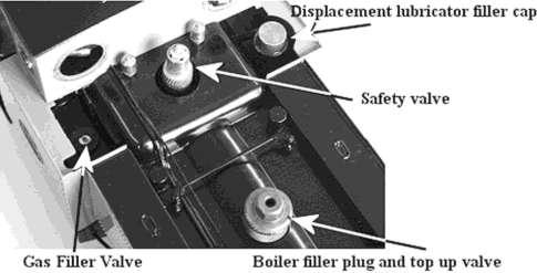
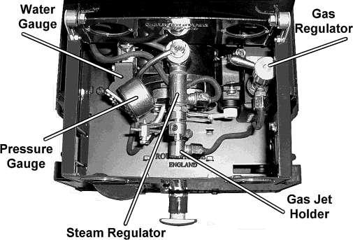
7 IDENTIFICATION OF PARTS OF THE LOCOMOTIVE 7
8 PREPARING FOR OPERATION The locomotive must be serviced before being operated. It is important to perform all the following operations. NOTE, check that the batteries in both the R/C transmitter and the locomotive are in good condition before attempting to operate the model - see the Radio Control section later on. 1) FILLING THE GAS TANK The filling of the gas tank should only be carried out in a wellventilated area, where there are no naked lights or other lighted locomotives close by. Ordinary Butane or Iso-butane gas (as used in gas cigarette lighters) is the preferred fuel, though for economy, the larger canisters as used for blowlamps or camping stoves etc. are better. The larger canisters have an EN417 threaded self sealing valve on top and require a special adapter to couple up to the filler valve on the locomotive and one is supplied in your tool kit. Mixed gasses are also available and may be used if ordinary butane or iso-butane are not available, but see the Gas System section for more information on this subject. Before attempting to fill the gas tank, make sure that the gas control valve is closed by turning it clockwise and that there are no other operating locomotives or naked flames nearby. The filler valve for the gas tank is the coal bunker on the right hand side and is accessed by lifting out the dummy coal load. Ensure that the gas canister is fitted with a correct adaptor then invert it and place its nozzle over the gas filler valve. Support the locomotive from underneath in the area of the tank, and press the canister down. The gas will be heard hissing as it enters the tank and a small amount will escape around the valve. This is quite normal and is the tank venting as the liquid enters. After about 20 to 30 seconds on the small tank and 40 to 50 seconds on the large tank, liquid gas will emerge from the valve showing that the tank is full. Remove the canister immediately. Filling times will vary depending on the temperature of the locomotive and are for guidance only. 8
9 2) FILLING THE BOILER There are two methods of filling the boiler 1/ Quick filling when cold. The dummy steam dome on top of the boiler can be lifted completely off to access the filler plug. The dome is a substantial and heavy item, being machined from solid brass. Take care not to drop it onto the locomotive, as the weight of it may damage the model. There is also a separate, removable plug in the top of the dome which is used when operating the top up system. Take care not to lose it. Remove the filler plug/filler valve assembly by unscrewing it with the large knurled body. Using the 60 ml syringe and plastic tube supplied, fill the boiler right to the top with clean water. Distilled water is recommended if available. As an alternative to distilled water if this is unavailable, clean tap water can be used in soft water areas. Also, rain water or water from a dehumidifier can be used provided that it is adequately filtered. Many people now use rain water passed through a coffee or wine making filter to remove any particles or debris in the water. Do not use deionised water as this may cause long term damage to the boiler and fittings. There has to be a space above the water to allow steam to be raised so, insert the end of the plastic pipe into the boiler and withdraw 30 ml of water with the syringe. Replace the filler plug finger tight then place the dummy steam dome over it. Note that there is a rubber O ring around the body of the filler plug. This is to retain the dome during normal operation. 2/ Pump bottle when hot or cold. Lift out the brass plug in the top of the steam dome, to give access to the top up valve. Fill the plastic pump bottle with clean water and pass the end of the plastic tube down through the hole in the dome and into the socket in the top of the top up valve. The socket has a slight taper in it, and a little downward pressure on the tube will ensure a good seal. 9
10 Pump the handle on the bottle to inject water into the boiler whilst maintaining this downward pressure. Keep pumping until the water level in the water gauge is almost at the top of the glass. Remove the plastic tube and replace the brass plug in the top of the dome. Note that a small amount of water will remain in the top of the valve but will evaporate away as the valve heats up. 3) LUBRICATION Regular lubrication of all working parts is important and should be carried out before each operating session. There are two types of lubrication required: The external moving linkages and bearings are lubricated with a medium oil such as motor engine oil, and the internal steam mechanisms such as cylinders, pistons and valves are lubricated with a special steam oil that is mixed with the steam. Infrequent external lubrication will allow parts to run dry, and over oiling can form pools around operating parts that attract dirt and grit. If too thin an oil is used it will evaporate very quickly as the loco gets hot leading to dry running. We recommend the use of a motor oil for external lubrication. When carrying out general lubrication, do not forget the regulator spindles (see Trouble Shooting section for further details of oiling the regulators). Internal lubrication is achieved by steam oil that is mixed with the steam in the displacement lubricator, housed in the left-hand side bunker. Lift out the dummy coal load and remove the knurled cap from the top. Slacken the knurled drain screw, located on the bottom of the lubricator beneath the foot plate, two or three turns but do not remove it. Any water in the lubricator will run out through the drain screw. Tighten the drain screw and refill with the steam oil supplied, then replace the cap and finally, the dummy coal load. Take time filling the lubricator, especially when cold, as the oil takes time to run down and may trap an air bubble. Both cap and drain screw are fitted with O rings and need only be closed finger tight. NOTE: Only special steam oil as supplied should be used in the lubricator and under no circumstances should ordinary oil be substituted, or damage may result. 10
11 4) LIGHTING THE BURNER WARNING: Before lighting read the section on the gas system under Troubleshooting later on and be aware of potential problems. If the gas system is not operating correctly, shut it off immediately or damage may result. Move the locomotive to another location before lighting. Butane is heavier than air and small pockets of gas can collect around the locomotive during filling. To light the burner, hold a lighted match or cigarette lighter over the top of the chimney and slowly open the gas regulator by turning it anti-clockwise. The gas should ignite almost immediately with a pop as the flame travels down the chimney and into the boiler tube. The burner should be audible but not too loud. NOTE as stated above, the gas regulator should be opened slowly until the burner ignites. If opened too quickly or too far, particularly when the engine is cold or if the gas tank has just been filled, it is possible that the flame may not ignite correctly, or may not travel back into the boiler flue but stay in the smoke box. If this should happen, the burner will sound quite different to normal and the blue flame will be visible in the smoke box if viewed down the chimney from a safe height. Should this happen, turn off the gas immediately or damage may result and then re-light it. If the problem persists and it is not possible to ignite the burner correctly, then a dirty jet should be suspected and cleaned as detailed in the Troubleshooting section. For the first couple of minutes keep the burner on low. This is important, as until it warms up, the flame will be a little unstable and turning it up too much could cause it to go out. Also, with a completely full tank, liquid gas could be drawn off instead of vaporized gas, which can also extinguish the flame. After a couple of minutes, the gas control valve can be opened more to speed up steam raising. Open the gas regulator slowly. The full range of adjustment (closed to fully open) is achieved within the first half to three quarters of a turn of the gas regulator knob any more is unnecessary. 11
12 RUNNING THE LOCOMOTIVE When full working pressure has been reached (between 35 and 40psi), the safety valve will start to blow off steam. Steam generation can be controlled by the gas valve in the right hand cab doorway. If the safety valve blows off frequently during running, then too much steam is being produced, which wastes water and gas. Turning down the burner will decrease the amount of steam created. Conversely, if steam pressure is not maintained during a run, then the burner should be turned up. After a few minutes of running it may be noticed that the gas pressure through the burner has increased. This is due to the gas tank becoming warmer and so increasing the gas pressure. Simply turn the gas down this may need to be performed several times during a run. The art of balancing steam generation to the operational requirement by the adjustment of the gas control valve will quickly be learned. The standard gas tank has a duration of about 25 minutes, though this will vary depending on the gas valve setting. The boiler should not be allowed to run dry, and the gas tank capacity is such that the gas should run out before the water but it is good practice to keep an eye on the water gauge as a check. When the gas is fully used up, the steam pressure in the boiler will be seen to gradually drop until the loco comes to a halt. Should the water expire before the gas is fully used, the pressure will drop rapidly and the loco will stop. Check the pressure gauge and water gauge if there is no steam pressure or visible water, turn off the gas. No damage will result if the gas is turned off immediately and the engine left to cool. Never add cold water to a hot, empty boiler in an attempt to cool it and never re-fill the gas tank without first checking the water level in the boiler. Ensure that the gas valve is completely turned off before refilling the gas tank. 12

13 RADIO CONTROL SYSTEM The locomotive is operated by a four channel radio control system. There are two main control levers on the radio transmitter, each of which is bi-directional and controls two functions. Speed and direction are controlled by the left hand lever. Left to right for forward or reverse (mid gear in the centre position) and up and down for regulator open or close. The right hand lever operates the steam whistle and drain cocks if fitted. Left to right for drain cocks open or closed (both drain cocks and chimney exhaust together in the centre position) and up and down for whistle valve open or close. Each control lever has two smaller trimmer levers, three of which (items 3, 4 and 6 in the illustration) should not be altered though the steam regulator trimmer (item 1), may require adjustment as referred to in a later chapter. For more information on using the Radio Control equipment, see the manufacturer s instruction booklet supplied with the Radio Control Set. INSERTINGTHE BATTERIES Batteries must be fitted to the locomotive before it can be run. To do this we need to remove the Left-Hand Side Tank. It is held in position by a single screw (the Side Tank Retaining Screw) which is located under the front footplate in front of the cylinder. U s i n g a s m a l l screwdriver, carefully remove this screw and place it safe. There is a weight in the front of the side tank that you need to be aware of before removing the side tank. Gently lift the side tank 13


14 up at the front and then ease it forward, taking care to hold onto the weight that is located in the front of the side tank. Batteries can now be fitted into the battery holder. The side tank can now be replaced. Hold the side tank as shown in the picture above. First, locate the tab at the upper rear of the side tank into its corresponding slot. D R I V I N G T H E LOCOMOTIVE First, turn on the transmitter and then switch on the receiver on the locomotive with the switch under the right hand side tank. You will then be able to gently sit the side tank down onto the three top slots and then into the remaining rear, bottom slot. Finally, replace the Side Tank Retaining Screw. Open the drain cocks 14
15 if fitted, by moving the right hand control lever fully over to the left. This will direct all exhaust out of the two pipes, facing forward, below the cylinders Select the desired direction of travel by moving the left hand lever fully over to either the left for forward or the right for reverse, and then slowly open the regulator a little by moving the left hand lever upwards. The locomotive will now move slowly off and the speed can be controlled by moving the lever slowly up or down. The regulator is quite sensitive and should be used with care. When the cylinders are cold, there will be a certain amount of water in the steam pipes and cylinders that will cause the locomotive to be a little jerky on initial movement. This is condensed steam and is a condition commonly known as priming and is quite normal. After a few moments, this will clear from the system as the cylinders quickly warm up and running will become smooth. The drain cocks can now be closed and the exhaust will exit from the chimney. If drain cocks are not fitted, the condensate will exhaust inside the chimney and drop down between the rails from a vent hole in the base of the smoke box. During the run, there will always be a small amount of condensate and oil dropping down through this vent hole whether drain cocks are fitted or not. Some of this will fall onto the hot super-heater inside the smoke box and can be heard as occasional spitting and popping and is quite normal. The art of fine control will soon be learnt with a little practice. The drain cocks, if fitted, can be opened and closed at any time, but it is good practice to open them before moving off, whenever the locomotive has been stationary for any length of time. With the right hand lever in the mid position, steam will exhaust from both the drain cock pipes beneath the cylinders and up the chimney at the same time. NOTE: Always keep the reversing lever fully over in the required direction when the engine is moving. The model is fitted with a 15
16 simple reversing valve gear and is not capable for 'notching up' (altering the valve cut off). Always bring the locomotive to a halt by closing the regulator before changing direction. Always ensure that the regulator is closed and the reversing lever is in the middle position (mid gear) before switching off the transmitter. Always switch off the receiver and transmitter when not in use to preserve battery life. It is good practice to switch on the transmitter before the receiver and switch off the receiver before the transmitter. In this way, the radio receiver is never on when the transmitter is switched off and so should always be under your control. When the batteries are getting low, a poor signal between transmitter and receiver will result and control of the engine will become erratic. The batteries should be replaced immediately. WATER TOP UP SYSTEM A water top up system is fitted to this model. This enables the water level in the boiler to be monitored and topped up to keep the engine in steam for long periods. Once the locomotive is in operation as detailed in the previous sections, water can be added to the boiler at any time during the run as follows. Fill the water pump bottle from your usual water supply. Bring the locomotive to a halt in a convenient place and carefully remove the brass plug from the top of the steam dome. NOTE: this will be hot and a pair of cotton gloves is provided in the tool kit. Push the end of the plastic tube down through the hole in the top of the steam dome and into the socket in the top of the water filling 16

17 valve. Whilst still holding the pipe in position and exerting slight downward pressure, pump the handle and this will inject water into the boiler. You will sometimes see water and air bubbles passing through the sight glass as you pump so allow the level to settle after a few pumps. Carefully pull the plastic pipe out of the water filling valve whilst steadying the engine. Sometimes, small particles of dirt will find their way in with the water and may cause the water filling valve to leak back a little when the pipe is removed. If this should happen, re-connect the pipe and give a further pump or two of water to clear it. As the filler valve sits vertically on top of the boiler, a small amount of water will remain in the socket once the plastic pipe has been removed and will boil off as the fittings return to normal operating temperature. This is quite normal. Replace the brass plug in the steam dome. 17
18 Once you start running your loco you will see the water level in the gauge slowly dropping. Note that air bubbles may sometimes form in the gauge giving a false reading but these can be pushed out by connecting the pipe from the water pump to the water filling connector and injecting some water. It is better to pump small amounts of water into the boiler at frequent intervals as this maintains a more even boiler pressure and prevents long waits while the cold water heats up and pressure returns to normal operating level. Aim to keep the water level between ½ and ¾ up the gauge and refill the gas tank as detailed earlier whenever it is empty. In this way, you can keep the loco in steam and at working pressure as long as you like. Don t forget to re-fill the displacement lubricator about every 45 minutes. STEAM WHISTLE The radio controlled steam whistle, if fitted, is mounted under the left hand side of the cab footplate and is operated by the right hand control stick on the transmitter. The control stick is normally at the bottom of its movement and pushing it up will open the whistle valve. It can be operated at any time provided there is sufficient steam pressure in the boiler, and the locomotive can be stationary or moving. The whistle incorporates a restrictor valve to keep the volume and pitch reasonably consistent over a wide range of boiler pressures and to reduce steam consumption. TROUBLESHOOTING & MAINTENANCE On a working model of this nature, it is important to keep all working parts well lubricated as detailed in the lubrication section. With constant heating up, cooling down and the stresses of hard work, screws etc. can work loose so, it is good practice to check all fixings and cylinder screws regularly, particularly when the model is new, but remember, never over tighten. 18
19 STORAGE BETWEEN OPERATING SESSIONS At the end of an operating session, it is good practice to clean the locomotive carefully with a clean soft cloth, and to oil all bright metal parts. Do not leave fuel or water in the tank or boiler for long periods. Do not store in places where the temperature may drop below freezing as water may still be present in the pipework. Ensure all controls are closed and the valve gear in mid gear. Ensure that radio control equipment is switched off. Remove batteries from the locomotive and the transmitter. Periodically it may be necessary to wash off all traces of dirt and old oil from the moving parts with paraffin (not thinners). This will remove any accumulations of dirt or grit. After washing with paraffin, leave to dry thoroughly overnight before re-oiling. It is most important that clean oil is applied and allowed to penetrate fully into all moving parts before the locomotive is run again. Manually moving the locomotive back and forth will assist in distributing the oil fully. Under normal operating conditions this procedure should not be required more than once or twice per year. STEAM LEAKS The cylinders are fitted with '0' rings in the glands sealing the piston and valve rods. These can be adjusted with a spanner if steam leaks develop. They should only be tightened just enough to stop the leak, as over tightening will affect the running of the model. Cylinder front and rear covers are retained by small brass cheese head screws (4 per cover) and these can be lightly nipped up from time to time, if steam can be seen leaking past the gaskets that seal them. The cylinder valve chests are sealed by O rings and should not require attention however, in the unlikely event of a leak developing at the joint, proceed as follows. Remove the relevant tank side as detailed in the radio control section. 19
 radio control on/off switch.")
 batteries.")
20 Inside the side tanks. Right hand side. 1) radio control on/off switch. 2) reversing servo. 3) receiver. Left hand side. 5) batteries. 6) whistle valve servo. 20
21 Remove the dummy cylinder cover by springing it gently outwards from the bottom then lifting the top off the back side of the valve chest. You will now see the four countersunk brass screws that fix the valve chest to the cylinder block. Carefully nip these down. There are access holes in the side tank base panels above, for access to the inside screws but it may be necessary to remove the battery pack or receiver first. REGULATOR NOT SHUTTING The steam regulator seating and seal can, after a period of time become worn or compressed so that when the lever on the radio control is fully closed, the locomotive still moves. To overcome this, a trimmer is fitted to the transmitter. This is the small lever at the side of the main control lever (see diagram earlier) and is set at the factory to the top of its slot. As wear takes place in the regulator, it can slowly be moved down the slot to compensate. When it reaches the bottom, it is time to reset it to the top and adjust the linkage between the servo and the regulator in the cab. If adjustment does not cure this problem, the internal '0' ring is probably damaged and requires replacement. Contact the factory for further advice. Periodic oiling of the gland will help keep the regulator working freely. Place a spot of motor oil between the gland nut and the regulator arm and work the regulator a few times. RADIO CONTROL The radio control equipment is housed in the side tanks. To access it, the outer side tank must be removed. Lay the locomotive on its side on a protective cloth with the side to be removed uppermost. Remove the cheese head screw that passes up through the front footplate, between the cylinder and the front step. It locates by tags, three along the top and two into the front of the coal bunkers. Carefully slide the outer side tank cover forward then upwards about 3mm then lift it clear. There is a large and heavy brass block in the front of the side tank, into which the retaining screw fastens and this sits loosely in the tank. Take care as you lift the tank away, not to drop this out as it may cause damage to the model. If the radio control gives problems, always check the batteries first and replace if necessary. 21
22 The radio control system is carefully set up during assembly of the locomotive. Do not alter any of the factory settings and ensure all trimmers are in the correct position as detailed in the Radio Control System section earlier. If problems occur whilst running the locomotive near other R/C engines, check that yours is on a different frequency. For more information on using the radio control equipment, see the manufacturer s instruction booklet supplied with the Radio Control Set. GAS SYSTEM Internally fired locomotives are fitted with our 'FG' type gas burner, which is set up and fully tested at the factory. This system is designed for use with Butane or Iso-Butane gas. Mixed gasses, i.e. Butane with a proportion of Propane mixed in, are available, and may be used if straight Butane is unavailable. These come in a variety of mixes ranging from 90/10 to 60/40 with one of the most common being 70/30. The figures refer to the proportions of the mix i.e. 70/30 contains 70% butane and 30% propane. If using mixed gasses, always choose the one with the largest proportion of butane. The addition of propane slightly alters the gasses properties. This can make the burner a little more difficult to light when cold or after filling the gas tank. Always open the regulator very slowly when lighting, and only just sufficient for ignition to take place. Opening too much too soon may extinguish the flame until the burner reaches normal operating temperature. The tiny jet in these units can become blocked by small particles of dirt making the burner difficult to light, burn weakly at normal operating temperatures*, burn in the smokebox or fail completely. If any of these should happen, clean out the jet as follows. (* On very cold days, a burner may start off burning weakly due to the temperature of the gas but should increase to its normal level as the engine warms up. This is quite normal) Carefully, disconnect the gas pipe from the gas jet holder using a 22
23 2BA spanner. Note when connecting or disconnecting the gas pipe and gas jet holder, do not use excessive force. Always hold the end of the gas burner near the air holes to support it otherwise it is possible to cause damage by bending the body. Slacken the screw retaining the gas jet holder and slide it out to the rear. Remove the jet from the jet holder using a 4BA spanner. Wash out the jet in fast evaporating thinner (Cellulose or similar). Blow through the jet from the front, which should clear most blockages. Although the hole through the jet is tiny, if you hold it up to the light you should be able to see quite clearly if it is blocked or not. If in doubt, fit a new jet. A spare gas jet is included with the toolkit. Do not use wire to clean the jet as this can damage the precision hole and may upset the delicate balance of the gas system. Reassemble in the reverse order, putting a small amount of PTFE tape round the thread of the jet. Ensure all connections are tight. When re-positioning the gas jet holder in the burner, ensure that it is pushed in as far as it will go. The gas regulator has a spindle O ring housed inside the body which may need lubrication from time to time if the control becomes spongy in operation, making precise gas control difficult. As stated in the lighting instructions earlier, the full range of adjustment for normal burner operation is achieved within the first full rotation of the regulator knob, and it should only be unscrewed more than this for maintenance purposes and when the tank is empty, and there are no naked lights nearby. To lubricate it, remove the knurled knob which is retained by a M3 socket grub screw (M1.5 AF Allen key required) in the side. This grub screw is accessed by first removing the brass lever which is screwed into the same hole. Beneath the knob is a back-lash spring which will slide off the spindle. Unscrew the hexagon retaining nut then screw the spindle out of the body. 23
24 The O ring can now be lubricated. Replace the spindle followed by the retaining nut. Slide the backlash spring over the spindle and replace the knob. Note that the grub screw that holds the knob in place tightens into a groove near the end of the spindle and should be in a position that allows the side handle to be screwed in and operate the regulator without fouling other controls or the cab side. WATER TOP-UP SYSTEM Over a period of time the end of the plastic filling tube that pushes in the boiler top-up valve will become a loose fit due to the heat of the fitting. To cure this, simply cut approximately 6mm from the end of the tube when necessary. Gas Regulator (Internal Parts) Regulator Body O ring to be lubricated Hexagon Retaining Nut Back-Lash Spring Regulator Spindle White PTFE Washer Knurled Knob 24
25 ROUNDHOUSE ENGINEERING CO. LTD. Units 6-9 Churchill Business Park. Churchill Road. Wheatley. Doncaster. DN1 2TF. England Telephone Fax EC Declaration Of Conformity I hereby declare that the model described: Model: Vale of Rheidol Serial No.: Conforms to the Pressure Equipment Directive 97/23/EC All components and assemblies have been designed and manufactured according to sound engineering practice (SEP) Description and specification of equipment covered Steam Generator and associated pipe work and fittings Model: Type 11 boiler Test pressure: 5.4 bar Volume: 248 ml Max working pressure: 2.7 bar Safety valve set pressure: 2.7 bar Maximum filling volume: 225 ml Year of manufacture: Same as Test Date. Serial No.: Test date: Vessel for Group 1 gasses and associated pipe work and fittings. Model: Type A K gas tank Serial No.: Test pressure: 34 bar Volume: ml Test date: Maximum permissible working pressure: 17 bar Maximum working temperature: 65 degrees C Intended use: storage of Liquefied Petroleum Gas (LPG) Year of manufacture: Same as Test Date. Signed R. Loxley (director) Dated.. 25
26 Please refer to the owner s handbook for your particular model of locomotive, for details on correct use of these pressure vessels. Pressure vessel care and maintenance Gas tank The gas tank is used for the storage of LPG (liquefied petroleum gas) in the form of butane, iso-butane or as set out in the owners handbook. The tank is fitted with a self-venting filler valve which contains no serviceable parts. Should the filler valve become defective in any way, it must be replaced with a new item. It is recommended that the gas tank should undergo the following checks, carried out by a competent person, club, society or pressure vessel manufacturer, every year:- 1) thorough visual inspection. And every five to ten years:- 1) hydrostatic pressure test to not less than 1.5 and not more than 2 times the maximum working pressure. Boiler The boiler is fitted with a safety valve to prevent the steam pressure rising above the maximum allowable working pressure. This is pre-set to open at between 2.38 bar (35 psi) and 2.72 bar (40 psi) and must not be adjusted to increase this value. If the safety valve becomes defective in any way, it should be replaced or returned to the factory for service and calibration. It is recommended that the boiler should undergo the following checks, carried out by a competent person, club, society, or pressure vessel manufacturer, every one to two years:- 1) thorough visual inspection. 2) hydrostatic pressure test to not less than 1.5 and not more than 2 times the maximum working pressure. 3) steam test to check the correct functioning of all steam controls, gauge and safety valve. 26
. Gas Jet Holder. 6). Gas Pipe. 7). Gas Burner fixing screw. 8). Air Inlet Holes.")
27 Gas Burner 1). Superheater Pipe. 2). Lubricator Pipe. 3). Gas Jet Holder retaining screw. 4). Gas Jet. 5). Gas Jet Holder. 6). Gas Pipe. 7). Gas Burner fixing screw. 8). Air Inlet Holes. 27

28 SERVICE AND PARTS If' any problems arise with this model which are not covered in these operating instructions or, spare parts are required, owners should first contact their local dealer. Your ROUNDHOUSE dealer is; If your dealer is unable to help, you may contact the Factory directly: ROUNDHOUSE ENGINEERING CO. LTD. Units 6-9 Churchill Business Park. Churchill Road. Wheatley. Doncaster. DN1 2TF. England Telephone Fax e- ONLINE
FOWLER Owners Handbook
 FOWLER Owners Handbook Operating Instructions IMPORTANT: Read these instructions carefully before operating the locomotive. The following items are required for running this engine and are not included
ACCUCRAFT UK LTD Unit 4, Long Meadow Industrial Estate, Pontrilas, Herefordshire. HR2 0UA Tel:
 1 ACCUCRAFT UK LTD Unit 4, Long Meadow Industrial Estate, Pontrilas, Herefordshire. HR2 0UA Tel: 01981 241380 www.accucraft.uk.com SAFETY FIRST OPERATING INSTRUCTIONS FLYING SCOTSMAN All our locomotives
Instruction Manual. B&O WITH SLOPE BACK TENDER Live Steam
 Instruction Manual B&O 0-4-0 WITH SLOPE BACK TENDER Live Steam AML is proud to offer the famous B&O 0-4-0 of the Baltimore Waterfront. Four switchers were built in 1912 by Baldwin for the B&O. Initially
Instruction Manual - War Department Baldwin Live Steam Instruction Manual
 Instruction Manual - War Department Baldwin 4-6-0 Live Steam Instruction Manual ACCUCRAFT UK LTD PINEWOOD COTTAGE BROCKHURST CHURCH STRETTON SHROPSHIRE S6Y 6QY TEL/FAX: +44 (0) 1694 723799 www.accucraft.uk.com
Instruction Manual. WSL #3 Heisler Live Steam
 Instruction Manual WSL #3 Heisler Live Steam Prototype Information Heisler No. 3, a three-feet, was built in 1900. Listed as builder s No. 1041, it carried 160lbs. boiler pressure, weighed 74,000lbs.,
ACCUCRAFT UK LTD Unit 8, Mynd Industrial Estate Church Stretton, Shropshire. SY6 6EA Tel:
 SAFETY FIRST ACCUCRAFT UK LTD Unit 8, Mynd Industrial Estate Church Stretton, Shropshire. SY6 6EA Tel: 01694 723799 www.accucraft.uk.com OPERATING INSTRUCTIONS GWR 61XX PRAIRIE TANK LOCOMOTIVE No 6106
ACCUCRAFT UK LTD Unit 8, Mynd Industrial Estate Church Stretton, Shropshire. SY6 6EA Tel:
 ACCUCRAFT UK LTD Unit 8, Mynd Industrial Estate Church Stretton, Shropshire. SY6 6EA Tel: 01694 723799 www.accucraft.uk.com OPERATING INSTRUCTIONS BR (Ex LSWR) B4 TANK LOCOMOTIVE No 30089 SAFETY FIRST
Code AWC20HP Air Compressor
 Code 951816 AWC20HP Air Compressor Index of Contents Index of Contents 02 Declaration of Conformity 02 What s Included 03 Safety Precautions 03 Specifications (AWC20HP Air Compressor) 04 Assembly Instructions
Instruction Manual D&RGW K-37 LIVE STEAM
 Instruction Manual D&RGW K-37 LIVE STEAM ACCUCRAFT COMPANY 33268 Central Avenue Union City, CA 94587 Tel: 510-324-3399 Fax: 510-324-3366 Copyright 2013 NOTES: Prototype Information The K-37 s were originally
D&RGW K #463
 Instruction Manual - D&RGW K-27 Live Steam ACCUCRAFT TRAINS 33268 Central Avenue Union City, CA 94587 Tel: (510) 324-3399 Fax: (510) 324-3366 Info@accucraft.com D&RGW K-27 2-8-2 #463 Instruction Manual
Instruction Manual D&RGW K-36 LIVE STEAM
 Instruction Manual D&RGW K-36 LIVE STEAM ACCUCRAFT COMPANY 33268 Central Avenue Union City, CA 94587 Tel: 510-324-3399 Fax: 510-324-3366 Email: info@accucraft.com Copyright 2009 NOTES: Prototype Information
RS(H)10,15 USER MANUAL. Read the complete manual before installing and using the regulator.
10,15 USER MANUAL. Read the complete manual before installing and using the regulator.") RS(H)10,15 USER MANUAL Read the complete manual before installing and using the regulator. WARNING INCORRECT OR IMPROPER USE OF THIS PRODUCT CAN CAUSE SERIOUS PERSONAL INJURY AND PROPERTY DAMAGE. Due to
RS(H)10,15 USER MANUAL Read the complete manual before installing and using the regulator. WARNING INCORRECT OR IMPROPER USE OF THIS PRODUCT CAN CAUSE SERIOUS PERSONAL INJURY AND PROPERTY DAMAGE. Due to
BSA6T and BSA64T Stainless Steel Bellows Sealed Stop Valves Installation and Maintenance Instructions
 1843950/3 IM-P184-03 ST Issue 3 BSA6T and BSA64T Stainless Steel Bellows Sealed Stop Valves Installation and Maintenance Instructions 1. General safety information 2. General product information 3. Installation
ST 18 Aluminium Gas Model
 ST 18 Aluminium Gas Model Operators Manual Issue 5 For correct operation of this autoclave it is essential that the chamber be filled with water up to the height of the studs before every use. DIXONS SURGICAL
Assembly Drawing: W-311B-A01, or as applicable Parts List: W-311B-A01-1, or as applicable Special Tools: , , &
 REDQ Regulators Model 411B Barstock Design Powreactor Dome Regulator OPERATION AND MAINTENANCE Contents Scope..............................1 Installation..........................1 General Description....................1
SEQUENTIAL SHOWER VALVE INSTRUCTION MANUAL PLEASE LEAVE THIS MANUAL WITH THE END USER
 SEQUENTIAL SHOWER VALVE INSTRUCTION MANUAL PLEASE LEAVE THIS MANUAL WITH THE END USER CONTENTS 1. INTRODUCTION & SAFETY 1 2. DIMENSIONS 2 3. TECHNICAL DATA 3 4. OPERATION 4 5. COMPONENTS 5 6. SITE INSTALLATION
THE BP-301 SERIES. Operating and Service Manual. Series includes all variants of BP-301 (LF 0.1Cv / MF 0.5Cv)
") THE BP-301 SERIES Operating and Service Manual Series includes all variants of BP-301 (LF 0.1Cv / MF 0.5Cv) Issue B October 2015 1 TABLE OF CONTENTS 1. Description... 3 2. Installation... 3 3. Operation...
THE BP-301 SERIES Operating and Service Manual Series includes all variants of BP-301 (LF 0.1Cv / MF 0.5Cv) Issue B October 2015 1 TABLE OF CONTENTS 1. Description... 3 2. Installation... 3 3. Operation...
ST 18 Aluminium Gas Model
 DIXONS SURGICAL INSTRUMENTS LTD, 1 ROMAN COURT HURRICANE WAY, WICKFORD BUSINESS PARK WICKFORD, ESSEX, SS11 8YB, UK TEL: +44 (0)1268 764614 - FAX: +44 (0)1268 764615 EMAIL: info@dixons-uk.com - WEB: http://www.dixons-uk.com
AIR COMPRESSOR OPERATING INSTRUCTION AND PARTS LIST
 AIR COMPRESSOR OPERATING INSTRUCTION AND PARTS LIST OIL-LESS TYPE IMPORTANT: PLEASE READ CAREFULLY BEFORE STARTING OPERATIONS. THE CONTENTS ARE FOR GENERAL INFORMATION OF ALL THE SIMILAR MODELS. Record
Crosby style JCE Safety Valve Installation, Maintenance and Adjustment Instructions CROSBY
 CROSBY Table of contents 1. Installation 1 1.1. Drainage 1 1.2. Discharge pipework 1 1.3. Preparation for installation 1 2. Pressure adjustment 1 3. Maintenance 1 4. Dismantling 1 4.1. All valve types
Installation and operating manual. Pneumatic control station LK product no: PCS 1-10
 LK product no: PCS 1-10 Article no: 74503 Revision:8 Article no: 74503 Revision: 8 2 (23) Contents 1. General information... 5 2. Safety precautions... 5 2.1 Significance of symbols... 5 2.2 Explanatory
Instruction Manual. Chesapeake & Ohio / Virginian Railway Allegheny Live Steam
 Instruction Manual Chesapeake & Ohio / Virginian Railway Allegheny 2-6-6-6 Live Steam Prototype Information The debate as to which is the largest steam locomotive ever built goes on to this day. Its always
Installation Instructions
 Installation Instructions COLONY SOFT 7.0 Centerset Lavatory Faucet 7.0 with Speed Connect Drain Congratulations on purchasing your American Standard faucet with the Speed Connect drain, a features found
Contents. Stainless Steel Side Block. 1.1 Separating the Side Block. Stainless Steel Side Block Reassembly of. Assembly from the Helmet Shell
 Separating the Side Block Assembly from the Helmet Shell Contents SSB-1 SSB-3 SSB-5 SSB-5 SSB-7 1.1 Separating the Side Block Assembly from the Helmet Shell 1.2 Side Block Assembly Replacement 1.3 Defogger
THE MF-400 SERIES. Operating and Service Manual. Series includes all variants of MF-400/401
 THE MF-400 SERIES Operating and Service Manual Series includes all variants of MF-400/401 Issue A October 2013 1 TABLE OF CONTENTS 1. Description... 3 2. Installation... 3 3. Operation... 4 4. Special
ATD LB PRESSURE BLASTER INSTRUCTION MANUAL
 ATD-8402 90LB PRESSURE BLASTER INSTRUCTION MANUAL SAVE THESE INSTRUCTIONS SAFETY INSTRUCTIONS FOR SANDBLASTER 1. Before opening the tank release the air pressure on the sand tank. To do this, turn off
LITTLE MAX MODEL 50G 50,000 BTU PROPANE TORCH
 LITTLE MAX MODEL 50G 50,000 BTU PROPANE TORCH INSTRUCTION MANUAL MODEL 50G PROPANE TORCH ASSEMBLY, TESTING, AND OPERATING INSTRUCTIONS PLEASE READ AND RETAIN THIS INFORMATION FOR FUTURE REFERENCE DO NOT
RARS5000 AIR BODY SAW OWNER S OPERATING MANUAL
 RARS5000 AIR BODY SAW OWNER S OPERATING MANUAL DESCRIPTION 1. No mar 2. No mar tip 3. Housing grip 4. Trigger 5. Air inlet 6. Air inlet plug 7. Plastic board Important! It is essential that you read the
LRS(H)4 USER MANUAL. Read the complete manual before installing and using the regulator.
4 USER MANUAL. Read the complete manual before installing and using the regulator.") LRS(H)4 USER MANUAL Read the complete manual before installing and using the regulator. WARNING INCORRECT OR IMPROPER USE OF THIS PRODUCT CAN CAUSE SERIOUS PERSONAL INJURY AND PROPERTY DAMAGE. Due to the
LRS(H)4 USER MANUAL Read the complete manual before installing and using the regulator. WARNING INCORRECT OR IMPROPER USE OF THIS PRODUCT CAN CAUSE SERIOUS PERSONAL INJURY AND PROPERTY DAMAGE. Due to the
THE HF-300 SERIES. Operating and Service Manual. Series includes all variants of HF-300/301
 THE HF-300 SERIES Operating and Service Manual Series includes all variants of HF-300/301 Issue A July 2015 1 TABLE OF CONTENTS 1. Description... 3 2. Installation... 3 3. Operation... 4 3.1. Spring Loaded...
V-24 OXYGEN LANCE VALVE
 INSTRUCTIONS for F-4737-U May, 2009 V-24 OXYGEN LANCE VALVE w/ C -Size Inlet w/ B -Size Inlet V-24 Oxygen Lance with 1/8" Pipe Holder... 9728D65... 2218939 V-24 Oxygen Lance with 1/4" Pipe Holder... 9728A65...
Pressure Dump Valve Service Kit for Series 2300 Units
 Instruction Sheet Pressure Dump Valve Service Kit for Series 00 Units. Overview The Nordson pressure dump valve is used to relieve hydraulic pressure instantly in Series 00 applicator tanks when the unit
Steam Locomotive Operating Procedures SVLS Locomotive 1973 Steam Up
 Steam Locomotive Operating Procedures SVLS Locomotive 1973 Steam Up These procedures have been developed to help both the novice and experienced engineer prepare the steam engine for service. While some
Budget Range Operators Handbook
 Budget Range Operators Handbook BAMBI AIR COMPRESSORS LTD 152 Thimble Mill Lane Heartlands Birmingham B7 5HT United Kingdom Tel: 0121 322 2299 Fax: 0121 322 2297 Email: sales@bambi-air.co.uk www.bambi-air.co.uk
APPROVED FOR USE IN SOUTH AFRICA STAINLESS STEEL STOVE
 AUTOMATIC GAS COOKER TWO BURNER STAINLESS STEEL STOVE THIS IS A LOW PRESSURE APPLIANCE TO BE USED ONLY WITH A 2.8kPa APPROVED SANS 1237 REGULATOR. REGULATOR NOT INCLUDED. PLEASE READ THESE INSTRUCTIONS
Pressure Dump Valve Service Kit for Series 3000 Units
 Instruction Sheet Pressure Dump Valve Service Kit for Series 000 Units. Overview The Nordson pressure dump valve is used to relieve hydraulic pressure instantly in Series 00, 400, 500, and 700 applicator
Installation & Operation Manual Proven Quality since 1892
 Content 1. ERIKS operating companies 2. Product description 3. Requirements for maintenance staff 4. Transport and storage 5. Function 6. Application 7. Installation 8. Maintenance 9. Service and repair
100L AIR COMPRESSOR MODEL NO: TIGER 16/1010 PART NO: OPERATION & MAINTENANCE INSTRUCTIONS LS01/13
 100L AIR COMPRESSOR MODEL NO: TIGER 16/1010 PART NO: 2244025 OPERATION & MAINTENANCE INSTRUCTIONS LS01/13 INTRODUCTION Thank you for purchasing this product. Before attempting to use this product, please
PRS(TC)4,8 USER MANUAL. Read the complete manual before installing and using the regulator.
4,8 USER MANUAL. Read the complete manual before installing and using the regulator.") PRS(TC)4,8 USER MANUAL Read the complete manual before installing and using the regulator. WARNING INCORRECT OR IMPROPER USE OF THIS PRODUCT CAN CAUSE SERIOUS PERSONAL INJURY AND PROPERTY DAMAGE. Due to
PRS(TC)4,8 USER MANUAL Read the complete manual before installing and using the regulator. WARNING INCORRECT OR IMPROPER USE OF THIS PRODUCT CAN CAUSE SERIOUS PERSONAL INJURY AND PROPERTY DAMAGE. Due to
P5513. Users Manual. Pneumatic Comparison Test Pump. Test Equipment Depot Washington Street Melrose, MA TestEquipmentDepot.
 Test Equipment Depot - 800.517.8431-99 Washington Street Melrose, MA 02176 TestEquipmentDepot.com P5513 Pneumatic Comparison Test Pump Users Manual PN 3963372 November 2010 2010 Fluke Corporation. All
Manual Actuated Boiler Blowdown Valves
 Manual Actuated Boiler Blowdown Valves Installation and Maintenance Instructions 1. Safety information 2. General product information 3. Installation 4. Operation 5. Maintenance 6. Spare parts p.1 1. Safety
VERTICAL AIR COMPRESSORS
 VERTICAL AIR COMPRESSORS MODEL NO: VE15C150, VE18C150, VE25C150 PART NO: 2226010, 2226020, 2226025 OPERATION & MAINTENANCE INSTRUCTIONS LS0715 INTRODUCTION Thank you for purchasing this CLARKE Vertical
Float Operated Level Controllers
 CONTENTS Float Operated Level Controllers IM0015 Nov. 2014 PAGE Introduction 1 Scope 1 Description 1 Specification 1 Control Installation 2 INTRODUCTION Side Mount Back Mount Prior to installing, the instructions
24L AIR COMPRESSOR OPERATION & MAINTENANCE INSTRUCTIONS MODEL NO: RANGER 7/240 PART NO: LS0913
 24L AIR COMPRESSOR MODEL NO: RANGER 7/240 PART NO: 2242000 OPERATION & MAINTENANCE INSTRUCTIONS LS0913 INTRODUCTION Thank you for purchasing this CLARKE 24L Air Compressor. Please read this manual fully
VERTICAL AIR COMPRESSORS
 VERTICAL AIR COMPRESSORS MODEL NO: VE11C150, VE15C150, VE18C150 PART NO: 2226005, 2226000, 2226015 OPERATION & MAINTENANCE INSTRUCTIONS LS0615 INTRODUCTION Thank you for purchasing this CLARKE Vertical
Model VR6 System. Installation, Operation & Maintenance
 Model VR6 System Installation, Operation & Maintenance General: All Archer Instruments chlorination systems are carefully designed and tested for years of safe, accurate field service. All Archer Instruments
Welcome to your new Firepod It will only work properly on Propane Gas (Also known as LPG and Patio Gas) with the special regulator supplied
 with the special regulator supplied") Welcome to your new Firepod It will only work properly on Propane Gas (Also known as LPG and Patio Gas) with the special regulator supplied To enjoy your Firepod safely please read the instructions and
Welcome to your new Firepod It will only work properly on Propane Gas (Also known as LPG and Patio Gas) with the special regulator supplied To enjoy your Firepod safely please read the instructions and
Chemical Injection Technologies Installation/Service Bulletin
 Bulletin 4002 Chemical Injection Technologies Installation/Service Bulletin SUPERIOR Series CL-16/26/56 Automatic Switchover Gas Chlorinator - Installation & Operation IMPORTANT!! READ THESE PRECAUTIONS
OPERATING INSTRUCTIONS
 0/05 OPERATING INSTRUCTIONS for gas pressure regulators PN0 with integrated slam shut valve (SSV) and integrated limited capacity safety relief valve (RV) MR 25 F0, MR 25 SF0 p e 20 kpa - 0 MPa (0,2-0
Assembly-, installation- and maintenance instruction manual for bladder accumulators IBV / EBV , top reparable
 Page 1 von 8 Assembly-, installation- and maintenance instruction manual for bladder accumulators IBV / EBV 100-575, top reparable Content Seite 0 Legend 2 1 Overview 2 2 Accumulator assembly and installation
! WARNING. Model PFC-1-G (direct acting) PFC-1-GR (reverse acting) Modulating Pneumatic Liquid Level Controls INSTRUCTION MANUAL MM-110B
 PFC-1-GR (reverse acting) Modulating Pneumatic Liquid Level Controls INSTRUCTION MANUAL MM-110B") INSTRUCTION MANUAL MM-110B Model PFC-1-G (direct acting) PFC-1-GR (reverse acting) Modulating Pneumatic Liquid Level Controls APPLICATIONS: Use with other pneumatic devices, for liquid level sensing in
INSTRUCTION MANUAL MM-110B Model PFC-1-G (direct acting) PFC-1-GR (reverse acting) Modulating Pneumatic Liquid Level Controls APPLICATIONS: Use with other pneumatic devices, for liquid level sensing in
3/8" Dr. Air Butterfly Impact Wrench
 8192106 3/8" Dr. Air Butterfly Impact Wrench Owner s Manual Read and understand all instructions before use. Retain this manual for future reference. Specifications Construction: Polished aluminum and
Operation and Maintenance Instructions
 Hydratight Limited Bentley Road South Darlaston West Midlands WS10 8LQ United Kingdom Tel: +44 121 50 50 600 Fax: +44 121 50 50 800 E-mail: enquiry@hydratight.com Website: www.hydratight.com TOP COLLAR
SAPAG. Safety valves, type 5700 Storage, Use, Operation and Maintenance Instructions. IMPORTANT NOTICE
 SAPAG IMPORTANT NOTICE Contents Important notice 1 0 Valve identification 2 1 Storage 2 2 Installation 2 3 Operation 2 4 Maintenance 3 4.1 Dismantling 3 4.2 Inspection 3 4.3 Repair 3 4.4 Assembly 4 4.5
24L AIR COMPRESSOR MODEL NO: TIGER 11/250 PART NO: OPERATION & MAINTENANCE INSTRUCTIONS LS01/13
 24L AIR COMPRESSOR MODEL NO: TIGER 11/250 PART NO: 2244010 OPERATION & MAINTENANCE INSTRUCTIONS LS01/13 INTRODUCTION Thank you for purchasing this product. Before attempting to use this product, please
FILTER REGULATORS MODEL NO: CAT155 & CAT156 FITTING & MAINTENANCE INSTRUCTIONS PART NO: & ORIGINAL INSTRUCTIONS
 FILTER REGULATORS MODEL NO: CAT155 & CAT156 PART NO: 3120169 & 3120170 FITTING & MAINTENANCE INSTRUCTIONS ORIGINAL INSTRUCTIONS GC0117 INTRODUCTION Thank you for purchasing this CLARKE Filter/Regulator.
5 Gallon Pressure Pot with HVLP Spray Gun and Hose
 California Air Tools 5 Gallon Pressure Pot with HVLP Spray Gun and Hose Model No. 365 Technical Data Type of feed.pressure Maximum pressure in the tank... 0,413Mpa (60PSI) Working pressure in the tank.0,
WARNING: FOR OUTDOOR USE ONLY
 Certified to CSA International 4.96 US For Outdoor Gas Fireplaces A HIGHER STANDARD IN QUALITY AND APPEARANCE SAFE AND BEAUTIFUL OUTDOOR LARGO FIRE PIT FOR PROPANE AND *NATURAL GAS OWNER S MANUAL WARNING:
SPECIFICATIONS Type: Twin stack, single phase Tank: 4 gallon Air Output: PSI; PSI Max PSI: 125 PSI HP: 1.
 2 GALLON TWIN STACK AIR COMPRESSOR Model: 9526 DO NOT RETURN TO STORE. Please CALL 800-348-5004 for parts and service. CALIFORNIA PROPOSITION 65 WARNING: You can create dust when you cut, sand, drill or
OPERATION & MAINTENANCE INSTRUCTIONS
 1 /2 REVERSIBLE AIR DRILL MODEL NO: CAT123 PART NO: 3110879 OPERATION & MAINTENANCE INSTRUCTIONS GC1110 INTRODUCTION Thank you for purchasing this CLARKE product. Before attempting to use this product,
INSTALLATION INSTRUCTIONS MANUAL ON/OFF SAFETY VALVE/PILOT KIT MODEL GA9050A-1 (F0235)
") P/N 126905-01 Rev. B 11/2016 INSTALLATION INSTRUCTIONS MANUAL ON/OFF SAFETY VALVE/PILOT KIT MODEL GA9050A-1 (F0235) For All Single, Dual and Triple Burner Natural and Propane/LP Gas Logs P126905-01 For
P/N 126905-01 Rev. B 11/2016 INSTALLATION INSTRUCTIONS MANUAL ON/OFF SAFETY VALVE/PILOT KIT MODEL GA9050A-1 (F0235) For All Single, Dual and Triple Burner Natural and Propane/LP Gas Logs P126905-01 For
THE BP-690 SERIES. Operating and Service Manual. Series includes all variants of BP-LF/MF-690/691
 THE BP-690 SERIES Operating and Service Manual Series includes all variants of BP-LF/MF-690/691 Issue B April 2015 1 TABLE OF CONTENTS 1. Description... 3 2. Installation... 3 3. Operation... 4 4. Special
LIQUIP DRYBREAK COUPLER. API800 Series MAINTENANCE INSTRUCTIONS
 LIQUIP DRYBREAK COUPLER API800 Series MAINTENANCE INSTRUCTIONS API LOADING COUPLER TO API RP1004 June 2015 Issue: F M:\Product-Info\API8xx\6-Service-Maintenance\API800 MAINTENANCE INSTRUCTIONS 40183.doc
24L AIR COMPRESSOR MODEL NO: TIGER 8/260 PART NO:
 24L AIR COMPRESSOR MODEL NO: TIGER 8/260 PART NO: 1499490 OPERATION & MAINTENANCE INSTRUCTIONS ORIGINAL INSTRUCTIONS LS0918 - ISS 2 INTRODUCTION Before attempting to use this product, please read this
AIR RATCHET WRENCH MODEL NO: CAT21B & CAT90 OPERATING & MAINTENANCE INSTRUCTIONS PART NO: & GC05/14
 AIR RATCHET WRENCH MODEL NO: CAT21B & CAT90 PART NO: 3110400 & 3110846 OPERATING & MAINTENANCE INSTRUCTIONS GC05/14 INTRODUCTION Thank you for purchasing this CLARKE Air-Powered Ratchet Wrench. Before
EASTERN ENERGY SERVICES PTE LTD. 60 Kaki Bukit Place #02-19 Eunos Tech Park Singapore, SG Singapore Telephone: Fax:
 2 Table Of Contents 1. Introduction 3 2. About this Manual 3 3. Contacting YZ Systems 3 4. Vessel Components 4 5. Specifications 5 6. Application 6 7. Theory of Operation 7 8. DuraSite Installation & Use
Installation, Operating, Maintenance and Safety Instructions for. Pressurised water systems for boats
 FLOMAX-SYSTEM DOC532/11 Installation, Operating, Maintenance and Safety Instructions for FLOMAX-SYSTEM Pressurised water systems for boats CW343A FloMax System 12 volt d.c. CW344A FloMax System 24 volt
COMPRESSOR OPERATION & MAINTENANCE INSTRUCTIONS MODEL NO: WARRIOR 55 PART NO: (110V) , (230V) , LS0512
 , (230V) , LS0512") COMPRESSOR MODEL NO: WARRIOR 55 PART NO: (110V) 2323010, (230V) 2322020, OPERATION & MAINTENANCE INSTRUCTIONS LS0512 INTRODUCTION Thank you for purchasing this CLARKE Compressor. Before attempting to use
COMPRESSOR MODEL NO: WARRIOR 55 PART NO: (110V) 2323010, (230V) 2322020, OPERATION & MAINTENANCE INSTRUCTIONS LS0512 INTRODUCTION Thank you for purchasing this CLARKE Compressor. Before attempting to use
15ME-014 INSTRUCTION MANUAL OF STERN TUBE SEALING TYPE EVK2RV. URL
 15ME-014 E INSTRUCTION MANUAL OF STERN TUBE SEALING TYPE EVK2RV URL http://www.kemel.com CONTENTS [A] Installation [B] Piping [C] Inspection [D] Handling [E] Parts replacement intervals [F] Handling check
bathrooms.com Concentric Thermostatic Shower Mixers Cleaning and Care Installation Manual Contents
 bathrooms.com Concentric Thermostatic Shower Mixers Contents Page 3 - General Information & Safety Page 4 - Installation Page 5 - Concentric Valve Set-up Page 6 - Exposed fitting of Concentric Mixer Valves
24L OIL FREE AIR COMPRESSOR MODEL NO: TIGER 7/250 PART NO: OPERATION & MAINTENANCE INSTRUCTIONS LS10/13
 24L OIL FREE AIR COMPRESSOR MODEL NO: TIGER 7/250 PART NO: 2244030 OPERATION & MAINTENANCE INSTRUCTIONS LS10/13 INTRODUCTION Thank you for purchasing this product. Before attempting to use this product,
INFLATOR TDUX-IT-16 AND GAS CYLINDER E
 INFLATOR TDUX-IT-16 AND GAS CYLINDER E7512-0160 Operating manual Inflator TDUX-IT-16 together with the special gas cylinder E7512-0160 is specifically designed for inflating TDUX duct seals. The inflator
SUMMITTM 400 & 600. Natural Gas Barbecues. Step-By-Step Guide
 SUMMITTM 400 & 600 Natural Gas Barbecues Step-By-Step Guide W E B E R W E B E R W E B E R W E B E R Summit 400 NG Summit 600 NG CANADIAN GAS ASSOCIATION R A P P R O V E D WARNING: Follow all leak check
Latvin Luxury Shower Panel. Telephone Product Specification. ~ Minimum Working Pressure 1.0 bar ~ Maximum Working Pressure 3.
 Product Specification ~ Minimum Working Pressure 1.0 bar ~ Maximum Working Pressure 3.0 bar Latvin Luxury Shower Panel ~ Fixing Centres 150mm +/- 10mm ~ Outlet size 1/2" Bottom Outlet Always maintain a
WHEATLEY WHEATLEY SERIES 500 SWING CHECK VALVE. Installation, Operation and Maintenance Manual
 WHEATLEY SERIES 500 SWING CHECK VALVE STANDARD INTEGRAL SEAT & OPTIONAL REMOVABLE SEAT 2" FP - 6" FP 150# - 1500# 8" FP - 12" FP 150# - 900# API 6D and B16.34 2" FP - 4" FP 5000# DRILLING PRODUCTION VALVE
MODEL 200 KNIFE GATE VALVES INSTALLATION & MAINTENANCE MANUAL
 MODEL 200 KNIFE GATE VALVES INSTALLATION & MAINTENANCE MANUAL Index 1. List of components / General arrangement 2. Description 3. Handling 4. Installation 5. Actuators / Operation 6. Maintenance a. Changing
CRP INSTALLATION, OPERATING AND MAINTENANCE INFORMATION FOR INLINE SAMPLING VALVES
 CRP INSTALLATION, OPERATING AND MAINTENANCE INFORMATION FOR INLINE SAMPLING VALVES Sampling Valves Installation Commissioning and Operating Instructions SD IL 300 & SD IL 400 Inline Sampling Valve This
OPERATION MANUAL Please read this Operation Manual carefully before use, and file for future reference.
 English Lubrication Free Air Turbine Handpiece with Water Spray OPERATION MANUAL Please read this Operation Manual carefully before use, and file for future reference. OM-T0286E 001 Thank you for purchasing
310 SERIES TILT-TO-LOAD ROTATOR. The Specialist In Drum Handling Equipment
 OPERATOR S MANUAL FOR MORSE TILT-TO-LOAD DRUM ROTATOR SAFETY INFORMATION: While Morse Manufacturing Co. drum handling equipment is engineered for safety and efficiency, a high degree of responsibility
SEries 29 Hydrant valves installation, operation & maintenance manual
 Instruction for use Thank you for selecting an AVK product. With correct use, it will give long and reliable service. This manual has been prepared to assist you install, operate and maintain the valve
KTM OM-2 SPLIT BODY FLOATING BALL VALVES INSTALLATION AND MAINTENANCE INSTRUCTIONS
 Before installation these instructions must be fully read and understood SECTION 1 - STORAGE 1.1 Preparation and preservation for storage All valves should be properly packed in order to protect the parts
You have decided to buy an LP 10 E by STEYR SPORTWAFFEN the new dimension of match air pistols!
 Congratulations! You have decided to buy an LP 10 E by STEYR SPORTWAFFEN the new dimension of match air pistols! The world-beating air pistol with electronic trigger! The STEYR LP 10 probably is the most
SAILTEC, INC CONGER COURT, OSHKOSH, WI USA
 OK to make this valve hand tight. Pin Mount Style Integral lies 4-5 Degrees above Horizontal. If you store your Hunter "bow down" you will get air-lock in the Integral. Slot Mount Style Pump Body "Down"
Regulators repair and maintenance. XS Compact 2nd stage. January 2014 Rev XSC /3 Ed. C /14 1
 XS Compact 2nd stage January 2014 Rev XSC /3 Ed. C /14 1 XS Compact 2nd stage WARNING! This manual is intended for use by expert technicians who have already received training in equipment repairs and
TABLE OF CONTENTS SAFETY FIRST!...3 BASIC OPERATION...4 ADJUSTMENTS...5. Cocking Pressure...5. Three-Way Valve Adjustment...6
 TABLE OF CONTENTS SAFETY FIRST!...3 BASIC OPERATION...4 ADJUSTMENTS...5 Cocking Pressure...5 Three-Way Valve Adjustment...6 External Three-Way adjustment...6 In-Line Regulator...6 Ram to Cocking Block
Paintball Marker. User s Manual. 530 South Springbrook Road Newberg, OR 97132
 Paintball Marker User s Manual 530 South Springbrook Road Newberg, OR 97132 Component Concepts, Inc., 530 South Springbrook Road, Newberg, OR 97132 Phone: (503) 554-8095 Fax: (503) 554-9370 www.phantomonline.com
LNVx Gas Conversion Kit Instructions
 TB134 Issue 1.0 Nov 2018 Applies to models: LNVx LNVx Gas Conversion Kit Instructions +44 (0) 1460 53535 info@powrmatic.co.uk www.powrmatic.co.uk General Information Heater conversion between gases will
HORNE 20 THERMOSTATIC MIXING VALVE TYPE H-2003
 PO Box 7, Rankine Street Johnstone, Renfrewshire Scotland. PA5 8BD Tel: 01505 321 455 Fax: 01505 336 287 Email: technical@horne.co.uk Web: www.horne.co.uk HORNE 20 THERMOSTATIC MIXING VALVE TYPE H-2003
Installation Instructions
 Installation Instructions COLONY SOFT 7.0 Single Control Lavatory Faucet with Speed Connect Drain Congratulations on purchasing your American Standard faucet with the Speed Connect drain, a feature found
RC 195 Receiver-Controller
 Document No. 129-082 RC 195 Receiver-Controller Product Description The POWERS RC 195 Receiver-Controller is a pneumatic instrument that receives one, two or three pneumatic inputs. It produces a pneumatic
Installation Instructions
 LP and High Altitude LP Gas Conversion Kit For United States Installations Installation Instructions For Model Series *G6/PGF1 Furnaces, *L1/PGC1 Furnaces, and *R4/PPG1 Gas/Electric Appliances using Honeywell
Cleaning rod: spring steel, stainless steel or carbon fibre cleaning rod - only use a one-piece rod. Avoid using snakes.
 Telemark Biathlon Where performance and precision come together http://telemarkbiathlon.com Rifle Cleaning Date : July 19, 2013 Anschutz Rifle Manual - Click Here Izhmash 7-3 Rifle Manual - still looking
OPERATOR S MANUAL Ar-Gone Weld Gas Analyzer
 July 2011 OPERATOR S MANUAL Ar-Gone Weld Gas Analyzer WARNING! Before operating this product, read and understand this Operator s Manual. Become familiar with the potential hazards of this unit. Contact
SERVICE MANUAL SALAMANDER BROILERS RADIANT AND INFRARED 36RB 36IRB VULCAN C36RB C36IRB WOLF
 SERVICE MANUAL SALAMANDER BROILERS RADIANT AND INFRARED VULCAN 36RB 36IRB WOLF C36RB C36IRB This Manual is prepared for the use of trained Vulcan Service Technicians and should not be used by those not
256 Pneumatic Pressure Indicator
 256 Pneumatic Pressure Indicator 51425699 Copyright 2002 Slope Indicator Company. All Rights Reserved. This equipment should be installed, maintained, and operated by technically qualified personnel. Any
HOT SHOT OPERATING INSTRUCTIONS AND OWNER S MANUAL. Model SPC-500. (Propane Torch)
") OPERATING INSTRUCTIONS AND OWNER S MANUAL Model # SPC-500 READ INSTRUCTIONS CAREFULLY: Read and follow all instructions. Place instructions in a safe place for future reference. Do not allow anyone who
OPERATING INSTRUCTIONS AND OWNER S MANUAL Model # SPC-500 READ INSTRUCTIONS CAREFULLY: Read and follow all instructions. Place instructions in a safe place for future reference. Do not allow anyone who
G7S Hand Pump Owner s Manual
 G7S Hand Pump Owner s Manual Copyright Air Venturi 2018 Version 4-18 Specifications 24.80 inches long closed 43.31 inches long extended 4500 psi/310 bar max pressure Features Integral manometer (pressure
AIR HAMMERS MODEL NO: CAT138/CAT139 OPERATING & MAINTENANCE INSTRUCTIONS PART NO: / GC064
 AIR HAMMERS MODEL NO: CAT138/CAT139 PART NO: 3120152 /3120153 OPERATING & MAINTENANCE INSTRUCTIONS GC064 INTRODUCTION Thank you for purchasing this CLARKE Air Hammer. Before attempting to use this product,
TURBO SET 1000 E D $'9 5(9
 TURBO SET 1000 Instructions for use and maintenance HOW TO GAS WELD WITH TURBO SET 1000 With gas welding always work methodically : before starting a weld ensure that the parent metal in the weld area
AIR COMPRESSOR OPERATION & MAINTENANCE INSTRUCTIONS MODEL NO: CHAMP 3 PART NO: LS0115
 AIR COMPRESSOR MODEL NO: CHAMP 3 PART NO: 2225222 OPERATION & MAINTENANCE INSTRUCTIONS LS0115 INTRODUCTION Thank you for purchasing this CLARKE Air Compressor. Please read this manual fully before use