INSTRUCTIONS FOR THE INSTALLATION, COMMISSIONING AND MAINTENANCE
|
|
|
- Vivien Webster
- 5 years ago
- Views:
Transcription

1 BALL VALVE FULLY WELDED TECHNICAL MANUAL INSTRUCTIONS FOR THE INSTALLATION, COMMISSIONING AND MAINTENANCE MT 040/E 1 Edition 01/10/15 rev.02
2 TABLE OF CONTENTS 1.0 INTRODUCTION 1.1 MAIN SPECIFICATIONS 1.2 VALVE CONTROL 1.3 WARNINGS CONCERNING THE USE 2.0 INSTALLATION 2.1 GENERAL WARNINGS 2.2 GENERAL REQUIREMENTS 2.3 SPECIAL REQUIREMENTS 2.4 CONDITIONS OF USE 3.0 COMMISSIONING 3.1 PRESSURIZATION 3.2 INSPECTION OF THE EXTERNAL TIGHTNESS 3.3 INSPECTION OF THE INTERNAL TIGHTNESS 4.0 MAINTENANCE 4.1 GENERAL INSTRUCTIONS 4.2 REPLACEMENT OF THE FIRE SAFE RING (58) or OF THE O-RING (56) (112)-(169) 5.0 LUBRICATION 6.0 EMERGENCY SEAL 7.0 STORAGE 8.0 SUGGESTED SPARE PARTS 2
3 1.0 INTRODUCTION This manual aims to provide essential information for the installation, commissioning and maintenance of the Fully Welded ball valves. Moreover we consider it necessary to herewith provide a brief illustration of the valves main specifications. 1.1 MAIN SPECIFICATIONS The Fully Welded ball valves are cut-off devices fit for the use both on gaseous fluids and liquids for a wide range of pressures. The main specifications of these valves are: steel body with tail pieces fit for the flanged coupling and with machining for butt welding; parts in direct contact with the fluid treated with a nickel (or chromium)-based coating; soft insert on the seat for a better tightness also for uses on gaseous fluids; double block and bleed type seal seats. 1.2 VALVE CONTROL The valve opening and closing operations are performed with the lever control or with different types of controls; please kindly refer to the specific use and maintenance instructions for these last ones. 3
4 1.3 WARNINGS CONCERNIG THE USE The Fully Welded ball valves are fit to be used completely opened or completely closed: therefore they shall not be used for lamination. The position of the valve may be determined when the valve is assembled as follows: valve with lever control: the lever is in the direction of flow with open valve or perpendicular to the flow with closed valve; valve with hand wheel control or different control: the open and close position is specified by indicators placed on the control itself (see figure 1). Figure 1 4
5 2.0 INSTALLATION 2.1 GENERAL WARNINGS Before the installation, commissioning, or maintenance, the operators shall: o examine the safety devices applicable to the installation where they have to work; o obtain the necessary authorizations to work, when required; o equip oneself with the necessary individual protections (helmet, goggles, etc ); o make sure that the area where they have to work is equipped with the required collective protections and with the necessary safety signs. The handling of the equipment and of its components shall be carried out after evaluating that the lifting devices are fit for the loads to be lifted (lifting capacity and functionality). The handling of the equipment shall be carried out by using the lifting eyes arranged on the equipment itself. The use of motorized means is reserved to the personnel in charge of this. In case the installation of the system and of its accessories requires the application of compression fittings, these shall be installed by following the instructions of the compression fittings manufacturer. The choice of the compression fittings shall be compatible with the use specified for the equipment and with the plant specifications, where required. The commissioning shall be carried out by properly trained personnel. During the commissioning, not strictly necessary personnel shall be moved away and the prohibition area shall be properly signalled (signs, barriers, etc ). 5
6 2.2 GENERAL INSTRUCTIONS The valve installation shall be carried out in compliance with the prescriptions (laws or regulations) in force in the place of installation. In particular the specifications of natural gas plants shall be in compliance with the law provisions or regulations in force in the place of installation, or at least in compliance with the EN or EN regulations (we remind that the installation in compliance with such laws minimizes the risk of fire hazard). The valve is delivered without external pressure limiting devices; therefore it shall be installed by making sure that the operating pressure of the unit, where it is installed, never exceeds the value of the permissible maximum pressure (MOP). Only for limited periods of time peaks with value equal to 1.1 x MOP are permitted. The user, in case he considers it necessary, shall install suitable pressure limiting devices; he shall moreover arrange suitable venting or draining system to discharge the pressure and fluid inside the plant before carrying out any inspection or maintenance operation. We wish to remind, however, that the special design of the seal seats allows discharging to the line any overpressure that may be generated in the body cavity among the seal seats. 6
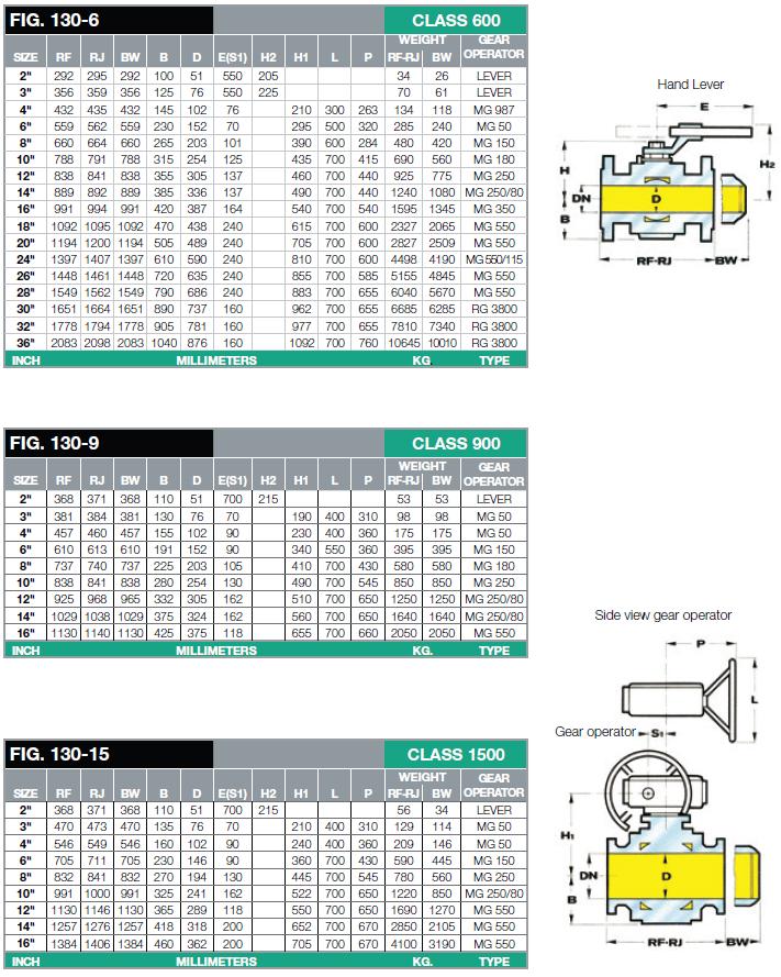
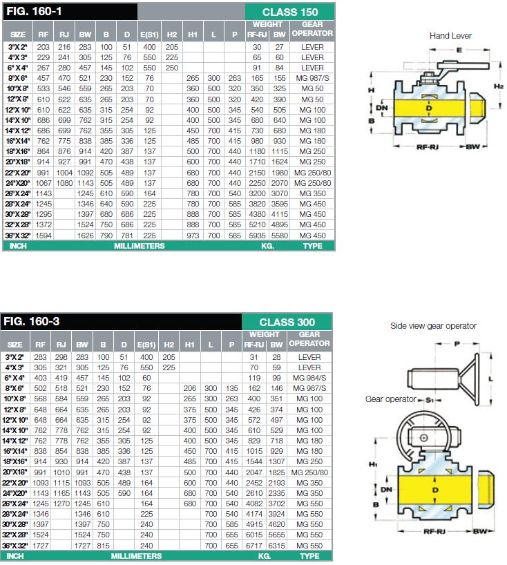
7 2.3 SPECIAL INSTRUCTIONS Before installing the valve it is necessary to be sure that: the valve may be inserted in the arranged space and it is sufficiently accessible for the following maintenance operations (see table 2); the upstream and downstream pipelines are at the same level as the inlet and outlet connections and they can support the weight of the valve; the pipeline inlet/outlet flanges are parallel to the valve seal surfaces; the inside of the valve is clean and the valve itself was not damaged during the transport; the upstream pipeline was cleaned in order to expel residual impurities such welding slag, sand, varnish waste, water, etc.. The valve does not have a preferential flow direction; therefore it may be installed in any position (vertical or horizontal flow). Starting from DN 150, the valve is equipped with its own supports; the user shall manufacture the plant so that it may support the valve itself and not overload the connections to the pipelines with further stresses. The connections to the inlet and outlet pipelines may be carried out: by means of standardized flanges the sizes and types of which are showed on the data plate ( see chapter 2.4 ); the choice of the connecting screws and of the seal gaskets shall be made by the installer who shall consider such information and the conditions of use in the place of installation; by means of a butt welding; in this case the installer shall take the necessary precautions in order to avoid thermally stressing the valve during the welding operations. During the welding operations the valve temperature shall not exceed the 130 value. We recommend, during the installation phase, to keep the ball in a fully open position, in order to prevent the seal seats and the ball surface from being damaged by foreign bodies or impurities. After the installation, open and close the valve in order to check its correct operation. 7

8 Table 2 8
9 9
10 10

11 11
12 2.4 CONDITIONS OF USE We recommend checking, before commissioning, that the conditions of use are in compliance with the equipment specifications. Such specifications are reported on the identification plates of each valve (figure 3). Figure 3 In particular we would like you to draw your attention to the following specifications: MOP max. permissible pressure at max. temperature; MOP min. permissible pressure at min. temperature; Tmin. And Tmax. design temperature (the minimum and maximum values are shown); the inlet and outlet connections class. Moreover, the user shall check that the used materials and the applied surface treatments, if any, are compatible with the expected use. Considering the valve geometric specifications, during the design phase no stresses due to traffic, wind, or seismic events were taken into consideration; therefore, the user shall take proper precautions in order to limit the effects of such events on the assembly, when these are expected. 12
 by means of the upstream process valve or of other systems arranged for this. 3.")


13 3.0 COMMISSIONING 3.1 PRESSURIZATION After the installation check that the connections to the line are correctly executed and that the vents and drainages on the plant, if any, are closed. Slowly pressurize the plant (or the plant section) by means of the upstream process valve or of other systems arranged for this. 3.2 CONTROL OF THE EXTERNAL TIGHTNESS The tightness test of the valve connections to the plant shall be carried out according to the provisions in force in the place of installation. The external tightness is ensured when coating the element under pressure with a foaming agent, no bubbles appear. In case of liquids, the tightness is ensured where there are no visible leaks from the connections. 3.3 CONTROL OF THE INTERNAL TIGHTNESS Thanks to the double block and bleed type of the seats, it is possible to check the internal tightness without disassembling the valve from the plant and without depressurizing the line where the valve is installed (see figure 4). After placing the valve in a fully open or closed position, keep the pressure in the line, open the drainage (pos.13 of fig.4) and check that there is no constant fluid leak from it. Figure 4 13
14 4.0 MAINTENANCE 4.1 GENERAL INSTRUCTIONS The inspection and maintenance interventions are strictly linked to the quality of transported fluid. It is therefore advisable to perform a preventive maintenance, of which periodicity, if not established by the regulations, is relevant to: the quality of the transported fluid; the cleanness and preservation state of the pipelines in the plant; in general, after the first start of the plants, more frequent maintenance services are required because of the poor cleanness inside the pipelines. The periodical maintenance concerns also the state of the external surfaces of the valve. In particular the surface protections shall be restored (usually the varnishing) in case they are worn. Before performing any intervention, make sure that the plant section where you operate has been upstream and downstream cut-off and that the pressure in the concerned pipeline section has been discharged. Besides, we recommend discharging the pressure from the valve body through the drain valve placed on the body of the valve itself (see pos. 13 figure 4). Moreover, make sure to have a series of recommended spare parts. The spare parts shall be Pietro Fiorentini Spa genuine spare parts. NOTE. The use of non genuine spare parts relieves the manufacturer from any liability. 14
15 4.2 REPLACEMENT OF THE FIRE SAFE RING (58) OR OF THE O-RING (56)-(112)- (169) The below mentioned operations may be carried out without removing the valve from the line. Check that the valve is completely closed (or open). Discharge the pressure from the valve body by leaving the drain valve open (13) REPLACEMENT OF THE O-RING (56) for DN 2"- 4" CLASS and DN 2"- 3" CLASS 600 WITH LEVER (figure 5) Unscrew the nut (52), remove the washer (75), with lever hub (74), unscrew the nut (48), remove the Belleville washer (49), the stem clamp (66), the second Belleville washer (49), unloosen the screws (18), remove the gland flange (33), the gland (50) and the O-ring (56) Clean and lubricate the O-ring seat and assemble the new O-ring (56) Assemble the gland (50), the gland flange (33), tighten the screws (18), assemble the Belleville washer (49), the stem clamp (66), the second Belleville washer (49), tighten the nut (48), assemble the lever hub (74), the washer (75) and tighten the nut (50). Close the drain valve (13). Figure 5 15
, the stem clamp (66) and the second Belleville washer (49), unloose the screws (18), remove the gland flange (33), the gland (50) and the fire safe ring (58). 4.2.")
16 4 2.2 REPLACEMENT OF THE FIRE SAFE RING (58) for DN 6" CLASS WITH LEVER ( figure 6 ) Remove the snap pin (71) the lever (47), and the lever hub (74), unscrew the nut (48), remove the Belleville washer (49), the stem clamp (66) and the second Belleville washer (49), unloose the screws (18), remove the gland flange (33), the gland (50) and the fire safe ring (58) Clean and assemble the new fire safe ring (58) Assemble the gland (50), the gland flange (33), tighten the screws (18). Assemble the Belleville washer (49), the clamp stem (66), the second Belleville washer (49), tighten the nut (48), assemble the lever hub (74) the lever (47) and the snap pin (71). Close the drain valve (13). Figure 6 16
17 4.2.3 REPLACEMENT OF THE O-RING (56) for DN 2" - 4 CLASS and DN 2"- 3" CLASS 600 WITH CONTROL ( figure 7 ) Unloose the screws (10) and remove the control Unloose the screws (15) remove the flange (34), the centring ring (130), unloose the screws (18), remove the gland flange (33), the gland (50) and the O-ring (56) Clean and lubricate the O-ring seat and assemble the new O-ring (56) Assemble the gland (50), the gland flange (33), tighten the screws (18), assemble the centring ring (130), the flange (34) and tighten the screws (15) Reposition the control and tighten the screws (10). Close the drain valve. In order to assemble the control, make reference to the relevant documentation. Figure 7 17
18 4.2.4 REPLACEMENT OF THE FIRE SAFE RING (58) AND OF THE O-RING (112)- (169) for DN 6" - 24" CLASS and DN 4" CLASS 600 WITH CONTROL ( figure 8 ) Unloose the screws (10) and remove the control Remove the tongue (11), the o-ring (169), unloose the screws (15), remove the flange (34), the O-ring (112), the gland (50) and the fire safe ring (58) Clean the seat of the fire safe ring (58), the slots of the O-rings (112)-(169) on the flange (34), assemble the new fire safe ring (58) and the new O-rings (112)-(169) Assemble the gland (50), the flange (34), tighten the screws (15) and assemble the stem key (11) Reposition the control and tighten the screws (10). In order to assemble the control, make reference to the relevant documentation. Figure 8 18
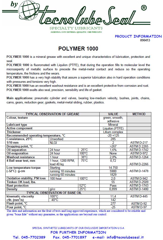
19 5.0 LUBRICATION The valves are already lubricated during the assembly phase (with the most suitable product for the operation if it is specified in the order) for the following reasons: 1) ease the components assembly 2) improve manoeuvrability 3) ease the preservation in case of warehouse storage. As regards the choice of lubricants, it is necessary to pay attention to the type of fluid to be cut-off, we suggest using the following listed lubricants in the below mentioned cases: a) oxygen: Molycote, Z powder, Fonblin oil, Safety Oxy Lube 200 EP (Tecnolube Seal), other lubricants or greases may generate explosive mixtures. b) Food products: Vaseline or similar non toxic materials. In all other cases, use products compatible with the expected conditions of use (temperatures) following the manufacturers suggestions and paying attention not to use corrosive products damaging the rubber parts. For all applications on gas (oxygen excluded), we suggest to use POLYMER 1000 grease (marketed by Tecnolube Seal) o similar products. For special applications we suggest to require information specifying in detail the type of fluid to be cut-off and the operating conditions 19
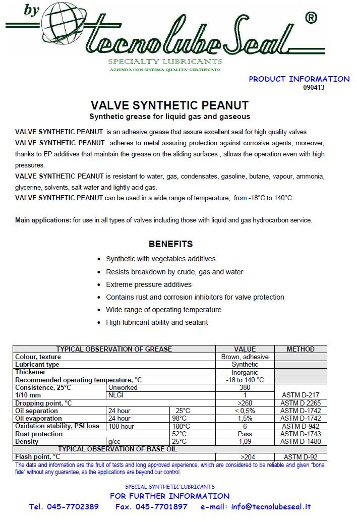
20 6.0 EMERGENCY SEAL For the emergency seal of the seats and of the stem (when required) we suggest to use VALVE PEANUT LUBE grease (trade mark TECNOLUBE SEAL), or similar lubricants. To inject the grease into the emergency lubricator (62) you must unloose the plug (1) of fig. 9 with a 360 rotation; inject the grease with a special injection pump. In order to inject the grease, it is necessary to use a pump with a max. operating pressure higher than 20 bar of the valve max. operating pressure at the moment of lubrication Figure 9 20
21 7.0 STORAGE The Fully Welded ball valves do not require specific precautions in case of storage for long periods; anyway it is recommended to pay attention to: avoid with ventilation, driers or heating, the formation of it condenses; the store has to be dry, deprived of dust and well ventilated and the temperature of the store, avoiding the freezing is up to +30 C; the present escorts must have consumed for first to get some times of storage the more possible brief; keep the valves in the original packing; keep the protections applied in the factory on the flanged connections; keep the valve in the closed position to safeguard the state of the tightness and valve seats; store the rubber parts away from direct sun light, in order to avoid a fast aging; particularly it will need to respect the directives for the storage of the rubbers (DIN 7716); protect the tightness seat from dust or other material. In case this happens, before installing it, carefully clean the tightness and ball seats. 8.0 SUGGESTED SPARE PARTS For the Fully Welded ball valves, the suggested spare parts are usually: the gaskets of the various joints (usually O ring); the fire safe ring. When ordering the spare parts, list: Type of valve Serial no. Year of manufacture Type of fluid used Part no. (position) Quantity 21
22 22
23 23

24 24

25 25
26 26

27 27
28 I dati sono indicativi e non impegnativi. Ci riserviamo di apportare eventuali modifiche senza preavviso. The data are not binding. We reserve the right to make modifications without prior notice. Pietro Fiorentini S.p.A. UFFICI COMMERCIALI: OFFICES: I MILANO Italy - Via Rosellini, 1 - Phone (10 linee a.r.) - Telefax sales@fiorentini.com I ARCUGNANO (VI) Italy - Via E. Fermi, 8/10 - Phone (10 linee a.r.) - Telefax arcugnano@fiorentini.com I NAPOLI Centro direzionale - Isola G 1 Phone Telefax napoli@fiorentini.com ASSISTENZA POST-VENDITA E SERVIZIO RICAMBI: SPARE PARTS AND AFTER-SALES SERVICE: I ARCUGNANO (VI) Italy - Via E. Fermi, 8/10 - Phone (10 linee a.r.) - Telefax service@fiorentini.com 28
MANUALLY OPERATED VALVE VLM SYNCROFLUX TECHNICAL MANUAL MT042/E
 MANUALLY OPERATED VALVE VLM SYNCROFLUX TECHNICAL MANUAL MT042/E INSTALLATION, COMMISSIONING AND MAINTENANCE INSTRUCTIONS CONTENTS 1.0 INTRODUCTION 1.1 MAIN CHARACTERISTICS 1.2 VALVE CONTROL 2.0 INSTALLATION
HBC/975 TECHNICAL MANUAL MT052/E INSTALLATION START-UP AND MAINTENANCE INSTRUCTION
 GAS SAFETY CUT-OFF DEVICE HBC/975 TECHNICAL MANUAL MT052/E INSTALLATION START-UP AND MAINTENANCE INSTRUCTION www.mvandc.com PRECAUTIONS GENERAL PRECAUTIONS - The apparatus described in this manual is a
CARTRIDGE FILTERS TECHNICAL MANUAL MT 080. Installation, commissioning and maintenance instructions. 08/02 Edition
 CARTRIDGE FILTERS TECHNICAL MANUAL MT 080 Installation, commissioning and maintenance instructions 08/02 Edition 1 2 CONTENTS 1.0 PAGE INTRODUCTION 1.1 MAIN FEATURES 1.2 OPERATION 1.3 CLOSING OF HEAD WITH
MT-239-E ENGLISH PRESSURE REGULATOR STAFLUX MINI TECHNICAL MANUAL INSTALLATION, COMMISSIONING AND MAINTENANCE INSTRUCTIONS
 MT-239-E ENGLISH PRESSURE REGULATOR STAFLUX MINI TECHNICAL MANUAL INSTALLATION, COMMISSIONING AND MAINTENANCE INSTRUCTIONS Technical manual MT 239-E 1 STAFLUX MINI Technical manual MT 239-E 2 Technical
Manual Actuated Boiler Blowdown Valves
 Manual Actuated Boiler Blowdown Valves Installation and Maintenance Instructions 1. Safety information 2. General product information 3. Installation 4. Operation 5. Maintenance 6. Spare parts p.1 1. Safety
PV4 and PV6 Piston Valves
 1181250/1 IM-P118-05 ST Issue 1 PV4 and PV6 Piston Valves Installation and Maintenance Instructions 1. Safety information 2. General product information 3. Installation 4. Commissioning 5. Operation 6.
Un-Pressurized Orefice Fittings FIO EZ. Parts List and Operation Instructions TECHNICAL MANUAL. Dn 2-6 Class Lbs
 Un-Pressurized Orefice Fittings FIO EZ Parts List and Operation Instructions TECHNICAL MANUAL Dn 2-6 Class 150-600 Lbs US US 2 FIO EZ - MT 108-US - 05-2016 FIO EZ Important Instructions US Pietro Fiorentini
Installation & Operation Manual Proven Quality since 1892
 Content 1. ERIKS operating companies 2. Product description 3. Requirements for maintenance staff 4. Transport and storage 5. Function 6. Application 7. Installation 8. Maintenance 9. Service and repair
WHEATLEY WHEATLEY SERIES 500 SWING CHECK VALVE. Installation, Operation and Maintenance Manual
 WHEATLEY SERIES 500 SWING CHECK VALVE STANDARD INTEGRAL SEAT & OPTIONAL REMOVABLE SEAT 2" FP - 6" FP 150# - 1500# 8" FP - 12" FP 150# - 900# API 6D and B16.34 2" FP - 4" FP 5000# DRILLING PRODUCTION VALVE
Needle valve. Contents. User s Manual. (1) Be sure to read the following warranty clauses of our product 1. (2) General operating instructions 2
 Be sure to read the following warranty clauses of our product 1. (2) General operating instructions 2") Serial No. H-V024-E-7 Needle valve User s Manual Contents (1) Be sure to read the following warranty clauses of our product 1 (2) General operating instructions 2 (3) General instructions for transportation,
Serial No. H-V024-E-7 Needle valve User s Manual Contents (1) Be sure to read the following warranty clauses of our product 1 (2) General operating instructions 2 (3) General instructions for transportation,
FTGS14 Ball Float Steam Trap DN15 (½") to DN25 (1")
 to DN25 (1)") 1458050/5 IM-P145-12 ST Issue 5 FTGS14 Ball Float Steam Trap DN15 (½") to DN25 (1") Installation and Maintenance Instructions 1. Safety information 2. General product information 3. Installation 4. Commissioning
1458050/5 IM-P145-12 ST Issue 5 FTGS14 Ball Float Steam Trap DN15 (½") to DN25 (1") Installation and Maintenance Instructions 1. Safety information 2. General product information 3. Installation 4. Commissioning
APT14, APT14HC and APT14SHC Spares 2
 6120251/7 IM-P612-06 ST Issue 7 APT14, APT14HC and APT14SHC Spares 2 Installation and Maintenance Instructions 1. Safety information 2. Replacement of trap and outlet check valve mechanism 3. Replacement
UIB30 and UIB30H Sealed Inverted Bucket Steam Traps for use with Pipeline Connectors
 1130050/4 IM-P113-02 ST Issue 4 UIB30 and UIB30H Sealed Inverted Bucket Steam Traps for use with Pipeline Connectors Installation and Maintenance Instructions 1. Safety information 2. General product information
INSTRUCTION MANUAL Pressure Relief Device LPT
 INSTRUCTION MANUAL Pressure Relief Device LPT 5COV475800 LPT REV00 CONTENT: 1 SAFETY 1.1 Safety instructions 2 1.2 Specified applications 2 1.3 Safety notes on the equipment operation 2 2 PRESSURE RELIEF
BSA6T and BSA64T Stainless Steel Bellows Sealed Stop Valves Installation and Maintenance Instructions
 1843950/3 IM-P184-03 ST Issue 3 BSA6T and BSA64T Stainless Steel Bellows Sealed Stop Valves Installation and Maintenance Instructions 1. General safety information 2. General product information 3. Installation
Installation, Operation and Maintenance Manual for Back Pressure Regulator
 Installation, Operation and Maintenance Manual for Back Pressure Regulator Model 8860 2009 Groth Corporation IOM-8860 Rev. B 12541 Ref. ID: 95565 Page 2 of 13 Table of Contents I. INTRODUCTION 3 II. DESIGN
SRV66 Sanitary Pressure Reducing Valve
 1866350/4 IM-P186-09 CH Issue 4 SRV66 Sanitary Pressure Reducing Valve Installation and Maintenance Instructions 1. Safety information 2. General product information 3. Installation 4. Operation 5. Commissioning
FLANGED TWO-PIECE BALL VALVES
 INTRODUCTION This instruction manual includes installation, operation, and maintenance information for FNW flanged split-body ball valves. This manual addresses lever operated ball valves only. Please
AVM7 Stainless Steel Thermostatic Air Vent
 1231850/4 IM-P123-23 ST Issue 4 AVM7 Stainless Steel Thermostatic Air Vent Installation and Maintenance Instructions 1. Safety information 2. General product information 3. Installation 4. Commissioning
BTM7, BTS7 and BTS7.1 Stainless Steel Thermostatic Clean Steam Traps
 1801050/10 IM-P180-05 ST Issue 10 BTM7, BTS7 and BTS7.1 Stainless Steel Thermostatic Clean Steam Traps Installation and Maintenance Instructions 1. Safety information 2. General product information 3.
THE HF-300 SERIES. Operating and Service Manual. Series includes all variants of HF-300/301
 THE HF-300 SERIES Operating and Service Manual Series includes all variants of HF-300/301 Issue A July 2015 1 TABLE OF CONTENTS 1. Description... 3 2. Installation... 3 3. Operation... 4 3.1. Spring Loaded...
KBV21i and KBV40i Key Operated Boiler Blowdown Valves Installation and Maintenance Instructions
 4059051/3 IM-P405-48 EMM Issue 3 KBV21i and KBV40i Key Operated Boiler Blowdown Valves Installation and Maintenance Instructions 1. Safety information 2. General product information 3. Installation 4.
Mounting and Operating Instructions EB 2558 EN. Self-operated Pressure Regulators. Type Pressure Build-up Regulator
 Self-operated Pressure Regulators Type 2357-31 Pressure Build-up Regulator with safety function and integrated excess pressure valve Type 2357-31 with non-return unit at port C Ports A and B with soldering
HM and HM34 Inverted Bucket Steam Traps Installation and Maintenance Instructions
 0670350/4 IM-S03-11 ST Issue 4 HM and HM34 Inverted Bucket Steam Traps Installation and Maintenance Instructions 1. Safety information 2. General product information HM Series 3. Installation 4. Commissioning
KTM OM-2 SPLIT BODY FLOATING BALL VALVES INSTALLATION AND MAINTENANCE INSTRUCTIONS
 Before installation these instructions must be fully read and understood SECTION 1 - STORAGE 1.1 Preparation and preservation for storage All valves should be properly packed in order to protect the parts
USER INSTRUCTIONS. NAF Duball DL Ball Valves. Installation Operation Maintenance. Experience In Motion. flowserve.com
 USER INSTRUCTIONS NAF Duball DL Ball Valves FCD NFENIM4167-01-A4 01/17 Installation Operation Maintenance 1 Experience In Motion Contents SAFETY 3 1 General 3 2 Lifting 4 3 Receiving Inspection 4 4 Installation
SAPAG. Safety valves, type 5700 Storage, Use, Operation and Maintenance Instructions. IMPORTANT NOTICE
 SAPAG IMPORTANT NOTICE Contents Important notice 1 0 Valve identification 2 1 Storage 2 2 Installation 2 3 Operation 2 4 Maintenance 3 4.1 Dismantling 3 4.2 Inspection 3 4.3 Repair 3 4.4 Assembly 4 4.5
FLANGED TWO-PIECE BALL VALVES
 INTRODUCTION This instruction manual includes installation, operation, and maintenance information for FNW flanged split-body ball valves. This manual addresses lever operated ball valves only. Please
SA Control Valve types: BM, BMF, BX, SB, NS, KA, KB, KC (Normally open) BMRA, BMFRA, BXRA, SBRA, NSRA, KX, KY (Normally closed)
 BMRA, BMFRA, BXRA, SBRA, NSRA, KX, KY (Normally closed)") 0366055/7 IM-S21-01 CH Issue 7 SA Control Valve types: BM, BMF, BX, SB, NS, KA, KB, KC (Normally open) BMRA, BMFRA, BXRA, SBRA, NSRA, KX, KY (Normally closed) Installation and Maintenance Instructions
0366055/7 IM-S21-01 CH Issue 7 SA Control Valve types: BM, BMF, BX, SB, NS, KA, KB, KC (Normally open) BMRA, BMFRA, BXRA, SBRA, NSRA, KX, KY (Normally closed) Installation and Maintenance Instructions
WHEATLEY Series 500 Swing Check Valve
 Document Number: TC003001-13 Revision: 02 WHEATLEY Series 500 Swing Check Valve Installation, Operation, and Maintenance Manual TABLE OF CONTENTS BILL OF MATERIALS...3 SCOPE...5 INSTALLATION AND OPERATION
Assembly-, installation- and maintenance instruction manual for bladder accumulators IBV / EBV , top reparable
 Page 1 von 8 Assembly-, installation- and maintenance instruction manual for bladder accumulators IBV / EBV 100-575, top reparable Content Seite 0 Legend 2 1 Overview 2 2 Accumulator assembly and installation
MSC-P and MSC-N Manifolds for Steam Distribution and Condensate Collection
 1170850/1 IM-P117-36 ST Issue 1 MSC-P and MSC-N Manifolds for Steam Distribution and Condensate Collection Installation and Maintenance Instructions 1. Safety information 2. General product information
Mounting and operating instructions EB 2530 EN. Self-operated Pressure Regulator. Pressure Reducing Valve Type M 44-2
 Self-operated Pressure Regulator Pressure Reducing Valve Type M 44-2 Type M 44-2, connection G 1 4, K VS = 0.15 Type M 44-2, connection G 1, K VS = 6 Fig. 1 Type M 44-2 Pressure Reducing Valve Mounting
INSTALLATION, MAINTENANCE & OPERATING INSTRUCTIONS 2-4 REDUCED PORT/ FULL PORT (5700/6700) ANSI CLASS 150/300/600/900/1500/2500 TRUNNION BALL VALVES
 ANSI CLASS 150/300/600/900/1500/2500 TRUNNION BALL VALVES") PBV-USA,Inc. 12735 Dairy Ashford. Stafford, Texas USA 77477 281-340-5400; 800-256-6193 FAX: 281-340-5499 INDUSTRIAL BALL VALVES IM0 69 April 2001 Rev 9 INSTALLATION, MAINTENANCE & OPERATING INSTRUCTIONS
PBV-USA,Inc. 12735 Dairy Ashford. Stafford, Texas USA 77477 281-340-5400; 800-256-6193 FAX: 281-340-5499 INDUSTRIAL BALL VALVES IM0 69 April 2001 Rev 9 INSTALLATION, MAINTENANCE & OPERATING INSTRUCTIONS
BT6HC Hygienic Sanitary Balanced Pressure Steam Trap for High Capacity and CIP/SIP Applications
 1800350/6 IM-P180-12 ST Issue 6 BT6HC Hygienic Sanitary Balanced Pressure Steam Trap for High Capacity and CIP/SIP Applications Installation and Maintenance Instructions 1. Safety information 2. General
MST21 Stainless Steel Balanced Pressure Thermostatic Steam Trap
 1250650/6 IM-P125-07 ST Issue 6 MST21 Stainless Steel Balanced Pressure Thermostatic Steam Trap Installation and Maintenance Instructions 1. Safety information 2. General product information 3. Installation
KBV21i and KBV40i Air Actuated Boiler Blowdown Valves
 4059051/1 IM-P405-48 AB Issue 1 KBV21i and KBV40i Air Actuated Boiler Blowdown Valves Installation and Maintenance Instructions 1. Safety information 2. General product information 3. Installation 4. Commissioning
Spirax SafeBloc TM DBB3 Double Block and Bleed Bellows Sealed Stop Valve. 1. Safety information. 2. General product information. 3.
 1849050/3 IM-P184-09 ST Issue 3 Spirax SafeBloc TM DBB3 Double Block and Bleed Bellows Sealed Stop Valve Installation and Maintenance Instructions 1. Safety information 2. General product information 3.
S1, S2, S3, S5, S6, S7, S8, S12 and S13 Separators
 0231150/8 IM-P023-55 ST Issue 8 S1, S2, S3, S5, S6, S7, S8, S12 and S13 Separators Installation and Maintenance Instructions 1. Safety information 2. General product information 3. Installation 4. Commissioning
MODEL 200 KNIFE GATE VALVES INSTALLATION & MAINTENANCE MANUAL
 MODEL 200 KNIFE GATE VALVES INSTALLATION & MAINTENANCE MANUAL Index 1. List of components / General arrangement 2. Description 3. Handling 4. Installation 5. Actuators / Operation 6. Maintenance a. Changing
Dri-Line Mk2 Spirax-Monnier Compressed Air Drain Trap
 0509950/2 IM-P050-21 CH Issue 2 Dri-Line Mk2 Spirax-Monnier Compressed Air Drain Trap Installation and Maintenance Instructions 1. Safety information 2. General product information 3. Installation and
Spilt body Flange ball valve. TC-205MFF-PN1640 User Manual English Version. Document No: TC-205MFF-PN1640.Ur-manual. Date: 2007/04/2617. Version: 1.
 Spilt body Flange ball valve TC-205MFF-PN1640 Series PED Category I,II TC-205MFF-PN1640 User Manual English Version Use for company in Europe who will place the product on the market, please amend which
Steam Trap BK BK 212-ASME. Original Installation Instructions English
 Steam Trap BK 212.. BK 212-ASME EN English Original Installation Instructions 810609-02 1 Contents Page Important Notes Usage for the intended purpose... 3 Safety note... 3 Danger... 3 Attention... 3 Application
DISASSEMBLY AND ASSEMBLY INSTRUCTIONS FOR LIQUID RING COMPRESSORS
 DISASSEMBLY AND ASSEMBLY INSTRUCTIONS FOR LIQUID RING COMPRESSORS SA INTRODUCTION These instructions are for the maintenance personnel for maintenance and repair of compressors series SA. Disassembly and
CVS10 Sanitary Check Valves
 0299050/4 IM-P029-11 ST Issue 4 CVS10 Sanitary Check Valves Installation and Maintenance Instructions 1. Safety information CVS10 with soft seat 2. General product information 3. Operation 4. Installation
S1, S2, S3, S5, S6, S7, S8, S12 and S13 Separators Installation and Maintenance Instructions
 PREVIOUS REFERENCE NO. IMP02355 0231150/13 IMF0501ENISS2 CMGT S1, S2, S3, S5, S6, S7, S8, S12 and S13 Separators Installation and Maintenance Instructions 1. Safety information 2. General product information
6301 TYPE CAST IRON SAFETY VALVES
 Pressure (bar) 6301 TYPE CAST IRON SAFETY VALVES FEATURES The 6301 type safety valve is a device designed to protect installations against possible overpressure. It operates automatically and closes when
Apollo Standard Port, Full Port & One Piece Flanged Ball Valves Installation, Operation, & Maintenance Manual
 I854000.D Apollo Standard Port, Full Port & One Piece Flanged Ball Valves Installation, Operation, & Maintenance Manual Introduction This manual presents guidelines for the Installation, Operation and
Engineering Data Sheet
 Page 1 of 6 CE MARKING AND THE PRESSURE EQUIPMENT DIRECTIVE 97/23/EC Valves must be installed into a well designed system and it is recommended that the system be inspected in accordance with the appropriate
SV5 Safety Valve Installation and Maintenance Instructions
 3120036/3 IM-S13-12 CH Issue 3 SV5 Safety Valve Installation and Maintenance Instructions 1. General specification 2. Supply 3. Before fitting the valve 4. Installation 5. Damage prevention 6. Commissioning
WKM Model 320F Floating Ball Valve
 Date: 4 WKM Model 320F Floating Ball Valve Installation, Operation, and Maintenance Manual 1 Date: 4 All the information contained in this manual is the exclusive property of Cameron. Any reproduction
Assembly Drawing: W-311B-A01, or as applicable Parts List: W-311B-A01-1, or as applicable Special Tools: , , &
 REDQ Regulators Model 411B Barstock Design Powreactor Dome Regulator OPERATION AND MAINTENANCE Contents Scope..............................1 Installation..........................1 General Description....................1
Spiratec ST14, ST16 and ST17 Sensor Chambers and sensors
 0862050/1 IM-P086-18 MI Issue 1 Spiratec ST14, ST16 and ST17 Sensor Chambers and sensors Installation and Maintenance Instructions 1. Safety Information 2. General product information 3. Installation 4.
Steam Trap BK 15 (DN40, DN 50) Original Installation Instructions English
 Original Installation Instructions English") Steam Trap BK 15 (DN40, DN 50) EN English Original Installation Instructions 810682-03 1 Contents Page Important Notes Usage for the intended purpose... 4 Safety note... 4 Danger... 4 Attention... 4 Application
Steam Trap BK 15 (DN40, DN 50) EN English Original Installation Instructions 810682-03 1 Contents Page Important Notes Usage for the intended purpose... 4 Safety note... 4 Danger... 4 Attention... 4 Application
INSTALLATION, OPERATION & MAINTENANCE MANUAL
 INSTALLATION, OPERATION & MAINTENANCE MANUAL AWWA C500 SOLID WEDGE GATE VALVE 2 72 NRS and OS&Y Series 100 and Series 105 TABLE OF CONTENTS SECTION PAGE # Equipment List 2 General 3 Receipt and Inspection
SA121, SA122, SA123, SA128 and SA1219 Self-acting Temperature Control Systems (Dial Adjustment)
") 3820050/4 IM-P382-01 CH Issue 4 SA121, SA122, SA123, SA128 and SA1219 Self-acting Temperature Control Systems (Dial Adjustment) Installation and Maintenance Instructions 1. Safety information 2. Use 3.
3820050/4 IM-P382-01 CH Issue 4 SA121, SA122, SA123, SA128 and SA1219 Self-acting Temperature Control Systems (Dial Adjustment) Installation and Maintenance Instructions 1. Safety information 2. Use 3.
M33F ISO, M33S ISO and M33V ISO Ball Valves Installation and Maintenance Instructions
 BAC13365 IM-P133-65 CMGT Issue 2 M33F ISO, M33S ISO and M33V ISO Ball Valves Installation and Maintenance Instructions 1. Safety information 2. General product information 3. Installation 4. Commissioning
Mounting and Operating Instructions EB 3007 EN. Self-operated Pressure Regulators. Differential Pressure Regulators (opening) Type Type 42-25
 Type Type 42-25") Self-operated Pressure Regulators Differential Pressure Regulators (opening) Type 42-20 Type 42-25 Type 42-20 Differential Pressure Regulator Type 42-25 Differential Pressure Regulator Mounting and Operating
Self-operated Pressure Regulators Differential Pressure Regulators (opening) Type 42-20 Type 42-25 Type 42-20 Differential Pressure Regulator Type 42-25 Differential Pressure Regulator Mounting and Operating
S and SF Inverted Bucket Steam Traps
 0772150/6 IM-P077-02 ST Issue 6 S and SF Inverted Bucket Steam Traps Installation and Maintenance Instructions 1. Safety information 2. General product information 3. Installation 4. Commissioning 5. Operation
SCA Series Inverted Bucket Steam Traps
 0770050/5 IM-P077-06 ST Issue 5 SCA Series Inverted Bucket Steam Traps Installation and Maintenance Instructions 1. General safety information 2. General product information 3. Installation 4. Commissioning
Dri-Line Mk3 Monnier Compressed Air Drain Trap
 5044050/2 IM-P504-24 CH Issue 2 Dri-Line Mk3 Monnier Compressed Air Drain Trap Installation and Maintenance Instructions 1. Safety information 2. General product information 3. Installation and Operation
RS(H)10,15 USER MANUAL. Read the complete manual before installing and using the regulator.
10,15 USER MANUAL. Read the complete manual before installing and using the regulator.") RS(H)10,15 USER MANUAL Read the complete manual before installing and using the regulator. WARNING INCORRECT OR IMPROPER USE OF THIS PRODUCT CAN CAUSE SERIOUS PERSONAL INJURY AND PROPERTY DAMAGE. Due to
RS(H)10,15 USER MANUAL Read the complete manual before installing and using the regulator. WARNING INCORRECT OR IMPROPER USE OF THIS PRODUCT CAN CAUSE SERIOUS PERSONAL INJURY AND PROPERTY DAMAGE. Due to
CP10 Sensor Installation and Maintenance Instructions
 4030150/9 IM-P403-26 EMM Issue 9 CP10 Sensor Installation and Maintenance Instructions 1. Safety information 2. General product information 3. Installation 4. Maintenance 5. Spare parts Copyright 2017
1.0 - OPENING AND CLOSING THE DOOR
 The purpose of this manual is to provide the user with instructions on how to safely open and close, how to conduct routine maintenance, and how to install the PEI TWINLOCK Closure on a pressure vessel.
AVC32 Carbon Steel Air Vent for Steam Systems
 1234050/4 IM-P123-14 ST Issue 4 AVC32 Carbon Steel Air Vent for Steam Systems Installation and Maintenance Instructions 1. Safety information 2. General product information 3. Installation 4. Commissioning
Atmospheric relief valve type 1100 Installation and maintenance instructions
 SAPAG 1. Description Sapag atmospheric relief valves type 1100 have been selected for installation because of their performance features, reliability and ease of maintenance. They are designed to protect
DCV10 Stainless Steel Disc Check Valve for use with Condensate Pumps
 6018050/1 IM-P601-33 ST Issue 1 DCV10 Stainless Steel Disc Check Valve for use with Condensate Pumps Installation and Maintenance Instructions 1. Safety information 2. General product information 3. Installation
Telefon (+45) Telefax (+45)
 Telefax (+45)") Uni-Valve A /S VENTILER & INSTRUMENTER Telefon (+45) 43 43 82 00 Telefax (+45) 43 43 74 75 mail@uni-valve.com www.uni-valve.com UNI-S83 / S84 3/4-way ball valve Installation and Operating manual 3/4-WAY
Uni-Valve A /S VENTILER & INSTRUMENTER Telefon (+45) 43 43 82 00 Telefax (+45) 43 43 74 75 mail@uni-valve.com www.uni-valve.com UNI-S83 / S84 3/4-way ball valve Installation and Operating manual 3/4-WAY
G type DUCTED EXHAUST SAFETY VALVE 2871 AND 288X SERIES. Model/Ref:
 Model/Ref: 28713 www.lauridsenindustri.com CHARACTERISTICS The G type safety valves are dedicated to protect the equipment from potential overpressure. They are automatic and close when the pressure conditions
M45 ISO Ball Valve DN25 to 150 Installation and Maintenance Instructions
 BAC 13310 IM-P133-42 ST Issue 2 M45 ISO Ball Valve DN25 to 150 Installation and Maintenance Instructions 1. General safety information 2. General product information 3. Installation 4. Commissioning 5.
1200B2 Series Service Regulators. Instruction Manual
 00B Series Service Regulators Instruction Manual 00B Series Service Regulators 0 Elster American Meter 00B Series Service Regulators General Information The 00B Series Service Regulators are available
TSS21 Sealed Thermostatic Steam Tracer Trap
 1255050/4 IM-P125-10 ST Issue 4 TSS21 Sealed Thermostatic Steam Tracer Trap Installation and Maintenance Instructions 1. Safety information 2. General product information 3. Installation 4. Commissioning
INSTALLATION, OPERATION and MAINTENANCE MANUAL
 INSTALLATION, OPERATION and MAINTENANCE MANUAL TRUNNION MOUNTED BALL VALVE NEXTECH I ValvTechnologies, Inc. 5904 Bingle Road Houston, Texas 77092 U.S.A. Email: sales@valv.com www.valv.com 705_Nextech IOM
CA10S, CA14 and CA14S Air and Gas Traps
 1448150/9 IM-P148-13 ST Issue 9 CA10S, CA14 and CA14S Air and Gas Traps Installation and Maintenance Instructions 1. Safety information 2. General product information 3. Installation 4. Commissioning 5.
PULSAR4 Pressure regulating valve (Unloader)
") Ultimo aggiornamento: 20/04/18 PULSAR4 Pressure regulating valve (Unloader) At gun closure, the waterflow is discharged in bypass reducing the pressure in the system upstream of the valve. Technical manual:
Ultimo aggiornamento: 20/04/18 PULSAR4 Pressure regulating valve (Unloader) At gun closure, the waterflow is discharged in bypass reducing the pressure in the system upstream of the valve. Technical manual:
INSTALLATION, USE AND MAINTENANCE MANUAL STEEL BALL VALVES
 INSTALLATION, USE AND MAINTENANCE MANUAL EN - 1 INDEX: 1. FOREWORD Pag. 3 2. OPERATION CONDITIONS Pag. 3 3. RISK ASSESSMENT Pag. 3 LIMITS OF USE 4. TRASPORTATION AND STORAGE/WEARHOUSING Pag. 3 TRASPORTATION
BCV31 DN40 - Blowdown Control Valve
 4034850/5 IM-P403-71 AB Issue 5 BCV31 DN40 - Blowdown Control Valve Installation and Maintenance Instructions 1. Safety information 2. Application 3. Technical data 4. Operation 5. Installation 6. Flow
Differential Pressure Regulator Type Type 45-6 (0.1 to 1 bar, DN 15) Mounting and Operating Instructions EB 3226 EN
 Mounting and Operating Instructions EB 3226 EN") Differential Pressure Regulator Type 45-6 Type 45-6 (0.1 to 1 bar, DN 15) Mounting and Operating Instructions EB 3226 EN Edition March 2008 Contents Contents Page 1 Design and principle of operation...................
Differential Pressure Regulator Type 45-6 Type 45-6 (0.1 to 1 bar, DN 15) Mounting and Operating Instructions EB 3226 EN Edition March 2008 Contents Contents Page 1 Design and principle of operation...................
Regulator from 1800 B series
 Regulator from 1800 B series Regulator from 1800 B series Measuring of industrial gases frequently requests a precise pressure regulation for the purpose of dosage and proccesing. UNIS FAGAS has two kinds
TP1 and TP2 Temporary Cone Shaped Strainers
 1698051/2 IM-P169-07 ST Issue 2 TP1 and TP2 Temporary Cone Shaped Strainers Installation and Maintenance Instructions TP1 1. Safety information 2. General product information 3. Installation and commissioning
AE14 Automatic Air Vents for Liquid Systems Installation and Maintenance Instructions
 1490050/7 IM-P149-06 CMGT Issue 7 AE14 Automatic Air Vents for Liquid Systems Installation and Maintenance Instructions 1. General safety information 2. General product information 3. Installation 4. Commissioning
SA121, SA122, SA123, SA128 and SA1219 Self-acting Temperature Control Systems (Knob Adjustment)
") 3810050/5 IM-P381-01 CH Issue 5 SA121, SA122, SA123, SA128 and SA1219 Self-acting Temperature Control Systems (Knob Adjustment) Installation and Maintenance Instructions 1. Safety information 2. Use 3.
3810050/5 IM-P381-01 CH Issue 5 SA121, SA122, SA123, SA128 and SA1219 Self-acting Temperature Control Systems (Knob Adjustment) Installation and Maintenance Instructions 1. Safety information 2. Use 3.
RJ check valves Installation and Maintenance Instructions
 3.531.5275.200 Issue 3-2015 RJ check valves Installation and Maintenance Instructions The PED Directive 97/23/EC is repealed and replaced by the new PED Directive 2014/68/EU with effect from 19 July 2016.
DF1 and DF2 Diffusers
 1550650/4 IM-P155-07 ST Issue 4 and Diffusers Installation and Maintenance Instructions 1. Safety information 2. General product information 3. Installation 4. Commissioning 5. Operation 6. Maintenance
APCO ARV CLEAN WATER AIR RELEASE VALVES. Model 50A
 APCO ARV CLEAN WATER AIR RELEASE VALVES Model 50A Instruction D12013 February 2017 Instructions These instructions provide installation, operation and maintenance information for APCO ARV Clean Water Air
CAST IRON SAFETY VALVE TYPE 6301
 CHARACTERISTICS The 6301 safety valve is dedicated to protect the equipment from potential overpressure. This is an automatic device that closes when the pressure conditions are back to normal. It is a
MF2M Monnier Miniature Compressed Air Filter
 5040050 / 2 IM-P504-02 CH Issue 2 MF2M Monnier Miniature Compressed Air Filter Installation and Maintenance Instructions 1. Safety information 2. General product information 3. Installation and commissioning
Wafer Check Valve. Contents. User s Manual. (1) Be sure to read the following description of our product warranty 1
 Be sure to read the following description of our product warranty 1") Serial No. H-V066-E-3 Wafer Check Valve User s Manual Contents (1) Be sure to read the following description of our product warranty 1 (2) General operating instructions 2 (3) General instructions for
Serial No. H-V066-E-3 Wafer Check Valve User s Manual Contents (1) Be sure to read the following description of our product warranty 1 (2) General operating instructions 2 (3) General instructions for
THE BP-301 SERIES. Operating and Service Manual. Series includes all variants of BP-301 (LF 0.1Cv / MF 0.5Cv)
") THE BP-301 SERIES Operating and Service Manual Series includes all variants of BP-301 (LF 0.1Cv / MF 0.5Cv) Issue B October 2015 1 TABLE OF CONTENTS 1. Description... 3 2. Installation... 3 3. Operation...
THE BP-301 SERIES Operating and Service Manual Series includes all variants of BP-301 (LF 0.1Cv / MF 0.5Cv) Issue B October 2015 1 TABLE OF CONTENTS 1. Description... 3 2. Installation... 3 3. Operation...
VB85/ Pressure regulating valve (Unloader)
") Ultimo aggiornamento: 20/09/12 VB85/160 280 Pressure regulating valve (Unloader) At gun closure, the waterflow is discharged in bypass reducing the pressure in the system upstream of the valve. Technical
Ultimo aggiornamento: 20/09/12 VB85/160 280 Pressure regulating valve (Unloader) At gun closure, the waterflow is discharged in bypass reducing the pressure in the system upstream of the valve. Technical
PULSAR4 Pressure regulating valve (Unloader)
") Ultimo aggiornamento: 15/12/11 PULSAR4 Pressure regulating valve (Unloader) At gun closure, the waterflow is discharged in bypass reducing the pressure in the system upstream of the valve. Technical manual:
Ultimo aggiornamento: 15/12/11 PULSAR4 Pressure regulating valve (Unloader) At gun closure, the waterflow is discharged in bypass reducing the pressure in the system upstream of the valve. Technical manual:
Diaphragm Pressure Keeping Valve
 Product: Diaphragm pressure keeping valve Type: 620.D 622.D 623.D 624.D 625.D 626.D 627.D Please state here the exact type and serial number of your diaphragm pressure keeping valve. (can be read off the
Installation, operation & maintenance manual - original version
 Installation, operation & maintenance manual - original version AVK gate valves for water and wastewater Series 01, 02, 06, 12, 15, 18, 20, 26, 32, 33, 36, 38, 50, 55 and 636 COPYRIGHT AVK GROUP A/S 2018
CA44, CA44S, CA46 and CA46S Air and Gas Traps
 1484450/3 IM-P148-37 ST Issue 3 CA44, CA44S, CA46 and CA46S Air and Gas Traps Installation and Maintenance Instructions 1. Safety information 2. General product information 3. Installation 4. Commissioning
TD45 Thermodynamic Steam Trap Installation and Maintenance Instructions
 0685255/1 IM-P068-47 ST Issue 1 TD45 Thermodynamic Steam Trap Installation and Maintenance Instructions 1 General safety information 2 General product information 3 Installation 4 Commissioning 5 Operation
INSTALLATION, OPERATION AND MAINTENANCE MANUAL. Model Sanitary Vent SECTION I
 INSTALLATION, OPERATION AND MAINTENANCE MANUAL Model 1100 Sanitary Vent IOM-1100 03-17 ISO Registered Company SECTION I I. DESCRIPTION AND SCOPE The Model 1100 is a stainless steel sanitary vent designed
PRS(TC)4,8 USER MANUAL. Read the complete manual before installing and using the regulator.
4,8 USER MANUAL. Read the complete manual before installing and using the regulator.") PRS(TC)4,8 USER MANUAL Read the complete manual before installing and using the regulator. WARNING INCORRECT OR IMPROPER USE OF THIS PRODUCT CAN CAUSE SERIOUS PERSONAL INJURY AND PROPERTY DAMAGE. Due to
PRS(TC)4,8 USER MANUAL Read the complete manual before installing and using the regulator. WARNING INCORRECT OR IMPROPER USE OF THIS PRODUCT CAN CAUSE SERIOUS PERSONAL INJURY AND PROPERTY DAMAGE. Due to
PC3_ and PC4_ Pipeline Connectors
 1283050/4 IM-P128-06 ST Issue 4 PC3_ and PC4_ Pipeline Connectors Installation and Maintenance Instructions 1. Safety information 2. Description PC30 shown 3. Installation 4. Welding of pipeline connector
M10HTi ISO Tobacco Ball Valve Screwed, SW, BW and Flanged versions
 IM-P133-75 ST Issue 1 M10HTi ISO Tobacco Ball Valve Screwed, SW, BW and Flanged versions Installation and Maintenance Instructions 1. Safety information 2. General product information 3. Installation 4.
Pure-Flo Handwheel Operated Valves (903, 913, 963) Instruction Manual
 Instruction Manual") PFMM-08 Pure-Flo Handwheel Operated Valves (903, 913, 963) Instruction Manual This manual provides installation, operation and maintenance instructions for Pure-Flo Diaphragm Valves (with 903, 913, 963
PFMM-08 Pure-Flo Handwheel Operated Valves (903, 913, 963) Instruction Manual This manual provides installation, operation and maintenance instructions for Pure-Flo Diaphragm Valves (with 903, 913, 963