|
|
|
- Sharyl Lambert
- 5 years ago
- Views:
Transcription
1
2
3
4
5
6
7

, rebound, air spring pressure.")
8 Worldwide FOX.SHOX ( ) FORK FLOAT 27.5 Travel 5.5 in./140 mm 5.9 in./150 mm 6.3 in./160mm Features/Adjustments Factory FIT CTD w/adj; 140, 150, 160; Kashima Coated or anodized upper tubes, 1.5 tapered steerer, lever actuated Climb/Trail/Descend (3 position), Trail adjust range (1, 2, 3), rebound, air spring pressure. Factory FIT CTD Remote; 140, 150, 160; Kashima Coated or anodized upper tubes, 1.5 tapered steerer, remote actuated Climb/Trail/Descend (3 position), rebound, air spring pressure. Performance FIT CTD; 140, 150, 160; Anodized upper tubes, 1.5 tapered steerer, lever actuated Climb/Trail/Descend (3 position), rebound, air spring pressure. Evolution CTD; 140, 150, 160; Anodized upper tubes, 1.5 tapered steerer, lever actuated Climb/Trail/Descend (3 position), rebound, air spring pressure. Evolution CTD Remote; 140, 150, 160; Anodized upper tubes, 1.5 tapered steerer, remote actuated Climb/Trail/Descend (3 position), rebound, air spring pressure. Lower leg 15QR thru axle system, post style disc brake mounting Spring Air Riding style Trail, AM Sections Before You Ride Setting Fork Air Pressure Adjusting Rebound Climb, Trail, Descend Adjusting Trail Mode Using the CTD Remote Before You Ride Make sure that your fork is ready to ride 1. Check that quick-release levers are properly adjusted and tightened. 2. Inspect the entire exterior of your fork. The fork should not be used if any of the exterior parts appear to be damaged. Contact your local dealer or FOX for further inspection and repair. 3. Check your headset adjustment. If loose, adjust it accordingly to your bicycle manufacturer's recommendations. 4. Check that all brake cables or hoses are properly fastened. 5. Test the proper operation of your front and rear brakes on level ground. 6. Before every race or ride, clean the outside of your fork with only mild soap and water, and wipe dry with a soft dry rag. Do not spray water directly into the seal/upper tube junction. Do not use a high pressure washer on your fork. Setting Fork Air Pressure 34 FLOAT maximum air pressure is 110psi Sag should be set to 15 20% of total fork travel 1. Unscrew the blue air cap on top of the left fork leg counter-clockwise to expose the schrader valve. 2. Attach a FOX High Pressure Pump to the schrader valve. 3. Pump your fork to the appropriate pressure as listed in the 'Suggested starting points for setting sag' table below, then remove the pump. 4. Using your forks sag setting o-ring on the left upper tube (or temporarily install a zip tie to the upper tube), slide the o-ring (or zip tie) down against the fork dust wiper.
, position your bike next to a wall or table to support yourself. Mount your bicycle.")
 down against the fork dust wiper. 8. Dismount your bike without bouncing, to avoid further moving the o-ring or zip tie.")
9 5. Rotate the CTD lever to the Descend mode (the riders 1 o'clock position). If you have a Remote CTD fork, click the black release lever once to set the fork to Descend mode. 6. Dressed to ride (including a filled hydration pack, if you use one), position your bike next to a wall or table to support yourself. Mount your bicycle. Assume your riding position for at least 10 seconds, allowing the suspension to fully settle. Make sure you distribute your weight evenly between the saddle, handlebars and pedals. 7. While in your riding position, slide the o-ring (or zip tie) down against the fork dust wiper. 8. Dismount your bike without bouncing, to avoid further moving the o-ring or zip tie. Measure the distance between the dust wiper and the o-ring or zip tie. This is your sag measurement. Suggested sag measurements are listed in the table below. 9. Add or remove air pressure until your sag measurement is between 15-20% of your forks total travel. 10. Repeat steps 2-8 and recheck sag measurement. 11.When sag measurement is correct, screw the blue air cap on clockwise until snug. Suggested Starting Points for Setting Sag Rider Weight lbs/kgs 140mm 150mm 160mm psi 45psi 45psi psi 50psi 50psi psi 55psi 55psi psi 65psi 65psi psi 70psi 70psi psi 75psi 75psi psi 80psi 80psi psi 90psi 90psi psi 100psi 100psi psi 110psi 110psi Suggested Sag Measurements Travel 15% sag (Firm) 20% sag (Plush) 5.5 in./140mm.82 in./21mm 1.1 in./28mm 5.9 in./150mm.88 in./22mm 1.2 in./30mm 6.3 in./160mm.95 in./24mm 1.3 in./32mm Adjusting Rebound Rebound controls how fast the fork extends after compressing The red rebound adjuster is located at the bottom of the right fork leg. Rebound controls the rate of speed at which the fork extends after compressing. Turning the knob clockwise (in) slows down rebound; turning the knob counter-clockwise (out) speeds up rebound. Rebound damping should only be set after first setting your air pressure by measuring sag. 1. Make sure your CTD fork is in Descend mode (fully counter-clockwise). 2. Starting with the rebound adjuster fully open (counter-clockwise) push on the fork to compress it and feel its return speed. 3. Increase rebound damping by turning the red rebound knob in clockwise until when tested, the fork returns quickly but does not top out. Top out is felt when a fork fully extends too quickly and comes to an abrupt stop when it reaches full extension (you will hear/feel a small noise). Top out should be avoided through proper rebound setting. Climb, Trail, Descend Easy on-the-fly adjustments for unprecedented control and performance The blue CTD lever lets you to switch between the Climb, Trail, and Descend modes. Each mode is optimized for each specific type of terrain, providing exceptional performance and riding enjoyment with your fork. CTD allows for complete rider control as one can experiment using different modes on various different types of terrain. Climb Mode:
. This setting is most useful for climbing and sprinting.")


10 Rotate the blue CTD lever fully clockwise to set the fork in Climb mode. Climb mode is a very firm low-speed compression setting (not designed to be a solid lockout). This setting is most useful for climbing and sprinting. Trail Mode: Rotate the blue CTD lever to the middle setting to set the fork in Trail mode. Trail mode offers less compression damping than Climb mode. Use this setting when pedaling on undulating terrain, and for preventing excessive travel in technical riding situations (such as low-speed drops). Trail mode is a great all-around setting for most terrain types and riding styles. Descend Mode: Rotate the blue CTD lever fully counter-clockwise to set the fork to Descend mode. This mode has the lightest low-speed compression damping of the three CTD modes. Descend mode offers the most plush ride to ensure optimal traction over varied terrain. Adjusting Trail Mode


11 FIT CTD w/trail Adjust models allow for added fine tuning Factory CTD w/trail Adjust model forks feature a three-position Trail Adjust control that regulates low-speed compression damping only in Trail mode. For firmer low-speed compression in Trail mode, turn the black Trail Adjust knob clockwise. For lighter low-speed compression, turn the Trail Adjust knob counter-clockwise. Trail adjustments (soft, medium, firm) only function in Trail mode. Using the CTD Remote Easy on-the-fly adjustments for unprecedented control and performance The CTD Remote lets you to switch between the Climb, Trail, and Descend modes while riding. Each mode is optimized for a specific type of terrain, providing best performance and riding enjoyment. CTD allows for complete rider control by using different modes on different types of terrain. Climb Mode: Push the silver lever down to its lowest position to set the fork in Climb mode.
12 Climb mode is a very firm low-speed compression setting (not designed to be a solid lockout). This setting is most useful for climbing and sprinting. Trail Mode: From Climb mode, push the black release lever once and then push the silver lever down one click to the middle position to engage Trail mode. From Descend mode, push the silver lever down one click to the middle position to engage Trail mode. Trail mode offers less compression damping than Climb mode. Use this setting when pedaling on undulating terrain, and for preventing excessive travel in technical riding situations (such as low-speed drops). Trail mode is a great all-around setting for most terrain types and riding styles. Descend Mode: Push the black release lever in any setting to set the fork to Descend mode. Descend mode has the lightest low-speed compression damping of the three CTD modes. Descend mode offers the most plush ride to ensure optimal traction over varied terrain. FOX Factory, Inc FOX.SHOX

13 SHOCK FLOAT CTD Travel 5.50 x x x x x x x x 2.50 Features/Adjustments Factory FLOAT CTD w/adj BV; Kashima Coated or anodized air sleeve and body, lever actuated Climb/Trail/Descend (3 position), Trail adjust range (1, 2, 3), rebound, air spring pressure. Factory FLOAT CTD Remote BV; Kashima Coated or anodized air sleeve body, remote actuated Climb/Trail/Descend (3 position), rebound, air spring pressure. Performance FLOAT CTD BV; Anodized air sleeve and body, lever actuated Climb/Trail/Descend (3 position), rebound, air spring pressure. Evolution FLOAT CTD Remote; Anodized air sleeve and body, remote actuated Climb/Trail/Descend (3 position), rebound, air spring pressure. Evolution FLOAT CTD; Anodized air sleeve and body, lever actuated Climb/Trail/Descend (3 position), rebound, air spring pressure. Spring Air Riding style XC, Trail Sections Installing Your Shock Before You Ride Setting Shock Air Pressure Adjusting Rebound Climb, Trail, Descend Adjusting Trail Mode Using the CTD Remote Service Intervals Installing Your Shock Check for clearance before riding. If you are installing your shock on a bike for which the shock was not original equipement, follow the steps below to ensure proper clearance before riding.

14 1. Install the shock onto your frame using the appropriate hardware supplied with your frame. 2. Remove the air cap and let all air out of the main air chamber. 3. Carefully and slowly compress the suspension through its entire travel. 4. Check that no part of your shock contacts any portion of your frame or linkage as it cycles through its travel. 5. Pressurize your main air chamber to between psi to prepare to set sag as described in the "Setting Shock Air Pressure" section below. Before You Ride Make sure that your shock is ready to ride 1. Clean the outside of your shock with mild soap and water and wipe dry with a soft rag. Do not use any solvents or de-greasers as these products can damage the shock's exterior finish. Do not use a high pressure washer or spray water directly at the seal/shock body junction. 2. Inspect the exterior of your shock. The shock should not be used if any of the exterior parts appear to be damaged Contact your local FOX dealer or FOX directly for further inspection or repair. 3. Make sure that your quick-release levers (or thru-axles) are properly adjusted and tightened. 4. Check your headset adjustment. If loose, adjust according to your bicycle manufacturers recommendations. 5. Check that all brake cables or hoses are properly fastened. 6. Test the proper operation of your front and rear brakes on lever ground. Setting Shock Air Pressure FLOAT CTD shocks have a maximum pressure of 300psi Sag should be set to 15 20% of total shock travel 1. Unscrew the black air cap to expose the schrader valve. 2. Slide your shocks sag setting o-ring up against the shock dust wiper.
, position your bike next to a wall or table to support yourself. Mount your bicycle.")
15 3. Rotate the CTD lever to the Descend mode (fully counter-clockwise). If you have a FLOAT CTD Remote shock, click the black release lever once to set the shock to Descend mode. 4. Dressed to ride (including a filled hydration pack, if you use one), position your bike next to a wall or table to support yourself. Mount your bicycle. Assume your riding position for at least 10 seconds, allowing the suspension to fully settle. Make sure you distribute your weight evenly between the saddle, handlebars and pedals. 5. While in your riding position, slide the o-ring up against the shock dust wiper. 6. Dismount your bike without bouncing, to avoid further moving the o-ring. Measure the distance between the dust wiper and the o-ring. This is your sag measurement. Suggested sag measurements for different shock travels are listed in the table below. 7. Add or remove air pressure until your sag measurement is between 15-20% of your shocks total travel. 8. Repear steps 2-6 and recheck sag measurement. 9. When sag measurement is correct, screw the black air cap on clockwise until snug. Suggested Sag Measurements Shock Travel 15% Sag (Firm) 20% Sag (Plush) 1.00 in./25mm 0.15 in./3.7mm 0.20 in./5.0mm 1.25 in./32mm 0.19 in./4.8mm 0.25 in./6.4mm 1.50 in./38mm 0.23 in./5.7mm 0.30 in./7.6mm 1.75 in./44mm 0.27 in./6.6mm 0.35 in./8.8mm 2.00 in./51mm 0.30 in./7.6mm 0.40 in./10.2mm 2.25 in./57mm 0.34 in./8.5mm 0.45 in./11.4mm 2.50 in./64mm 0.40 in./9.6mm 0.50 in./12.8mm Adjusting Rebound Rebound controls how fast the shock extends after compressing
 slows down rebound, turning the red rebound knob counter-clockwise (out) speeds up rebound.")
 push down on the saddle to compress the shock and feel its return speed. 3.")
16 Rebound controls the rate of speed at which the shock extends after compressing. Turning the red rebound knob clockwise (in) slows down rebound, turning the red rebound knob counter-clockwise (out) speeds up rebound. Rebound damping should only be set after first setting your air pressure by measuring sag. 1. Make sure your CTD adjuster is set in Descend mode (fully counter-clockwise). 2. Starting with the rebound adjuster in the fully open position (counter-clockwise) push down on the saddle to compress the shock and feel its return speed. 3. Increase rebound damping by turning the red rebound knob clockwise (when viewed from the end of the shock with the air valve) until when tested, the shock returns quickly but does not top out. Top out is felt when a shock fully extends too quickly and comes to an abrupt stop when it reaches full extension (you will hear/feel a small noise). Top out should be avoided through proper rebound setting. Climb, Trail, Descend Easy on-the-fly adjustments for unprecedented control and performance The blue CTD lever lets you to switch between the Climb, Trail, and Descend modes. Each mode is optimized for each specific type of terrain, providing exceptional performance and riding enjoyment with your shock. CTD allows for complete rider control as one can experiment using different modes on various different types of terrain. Climb Mode: Rotate the blue CTD lever fully clockwise to set the shock in Climb mode. Climb mode is a very firm low-speed compression setting (not designed to be a solid lockout). This setting is most useful for climbing and sprinting. Trail Mode:
.")
17 Rotate the blue CTD lever to the middle setting to set the shock in Trail mode. Trail mode offers less compression damping than Climb mode. Use this setting when pedaling on undulating terrain, and for preventing excessive travel in technical riding situations (such as low-speed drops). Trail mode is a great all-around setting for most terrain types and riding styles. Descend Mode: Rotate the blue CTD lever fully counter-clockwise to set the shock to Descend mode. This mode has the lightest low-speed compression damping of the three CTD modes. Descend mode offers the most plush ride to ensure optimal traction over varied terrain. Adjusting Trail Mode FLOAT CTD w/adj models allow for added fine tuning

 only function in Trail mode.")
18 FLOAT CTD w/adj model shocks feature a three-position Trail Adjust control that regulates low-speed compression damping only in Trail mode. 1 is the softest setting, 2 is the medium setting, and 3 is the firmest setting. To adjust Trail mode, first gently pull out on the black Trail adjust knob and turn it, lining up the arrow with your desired Trail mode setting number. Trail adjustments (1, 2, 3) only function in Trail mode. Using the CTD Remote Easy on-the-fly adjustments for unprecedented control and performance

19 The CTD Remote lets you to switch between the Climb, Trail, and Descend modes while riding. Each mode is optimized for a specific type of terrain, providing best performance and riding enjoyment. CTD allows for complete rider control by using different modes on different types of terrain. Climb Mode: Push the silver lever down to its lowest position to set the fork in Climb mode. Climb mode is a very firm low-speed compression setting (not designed to be a solid lockout). This setting is most useful for climbing and sprinting. Trail Mode: From Climb mode, push the black release lever once and then push the silver lever down one click to the middle position to engage Trail mode. From Descend mode, push the silver lever down one click to the middle position to engage Trail mode. Trail mode offers less compression damping than Climb mode. Use this setting when pedaling on undulating terrain, and for preventing excessive travel in technical riding situations (such as low-speed drops). Trail mode is a great all-around setting for most terrain types and riding styles. Descend Mode: Push the black release lever in any setting to set the fork to Descend mode. Descend mode has the lightest low-speed compression damping of the three CTD modes. Descend mode offers the most plush ride to ensure optimal traction over varied terrain. Service Intervals
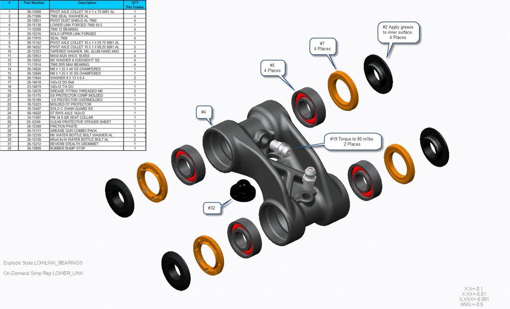
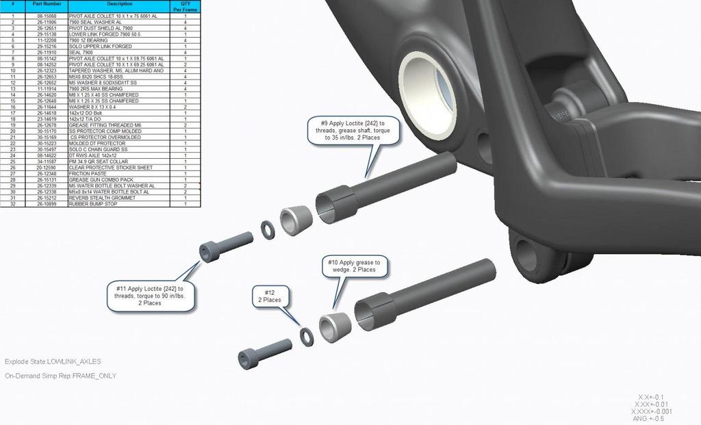
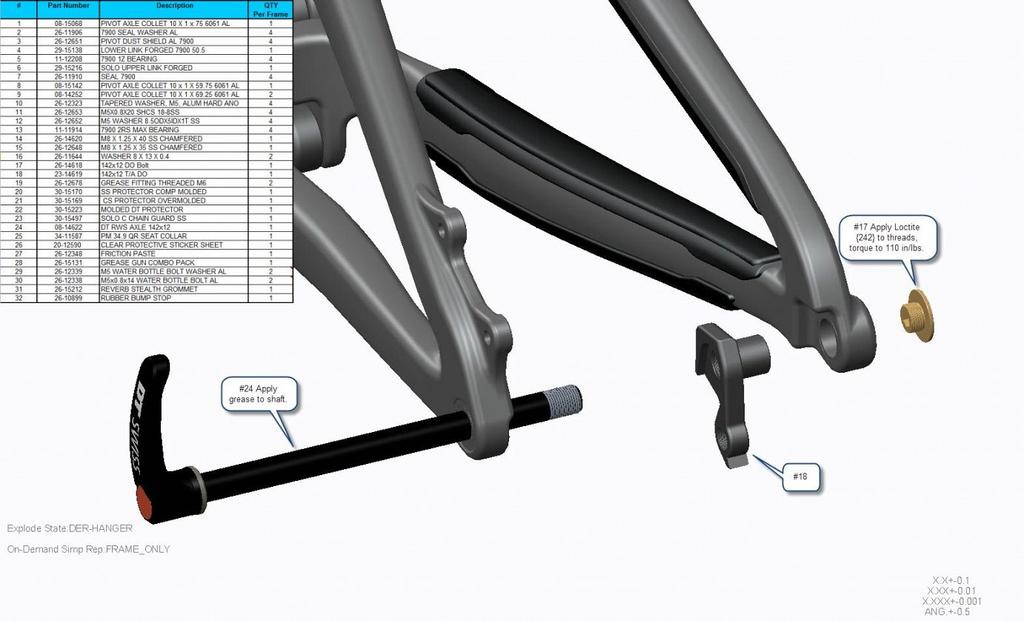
MACH 6 TECH SCHEMATIC
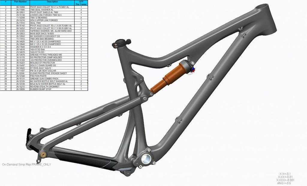
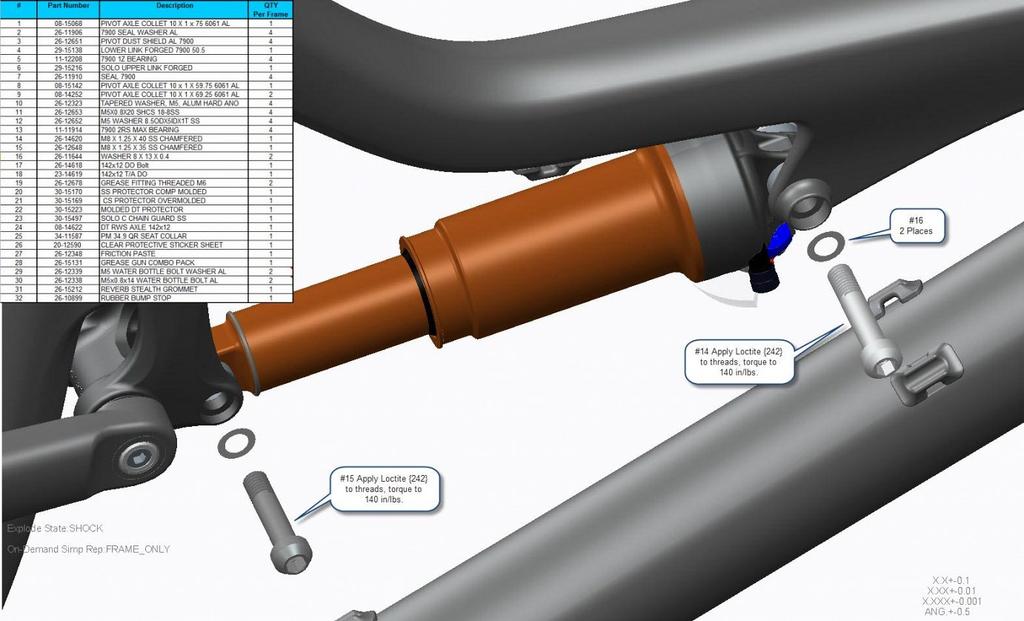
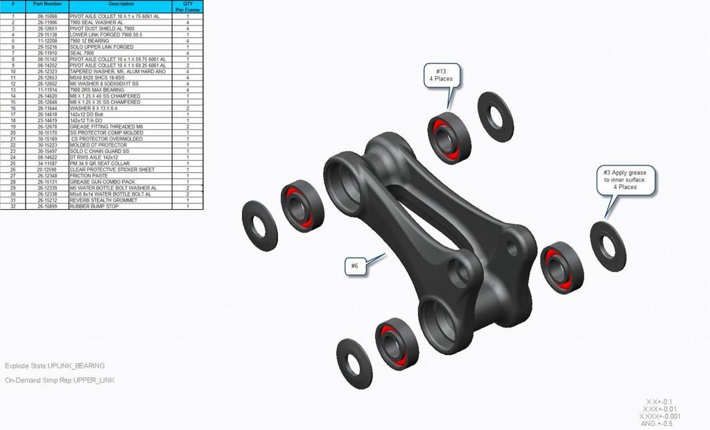
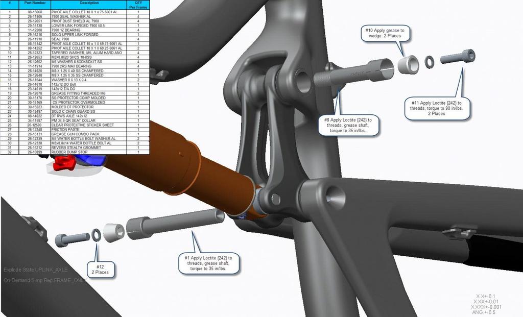
 MACH 6 TECH SCHEMATIC 13 2 1 4 3 5 6 12 11 Item no. Qty 1 4 2 4 3 1 4 1 5 2 6 2 7 4 8 4 9 1 10 1 11 1 12 1 13 1 7 8 Description Mach Rocker V3 Upper Bolt Grey DW Link V2 Fwd Bearing Pivot rear der hanger
Spot Rollik 607 Suspension Setup Guide Table of Contents
 Spot Rollik 607 Suspension Setup Guide Table of Contents Warning Intended Use A. Rear Shock Pressure/Sag Setting B. Rear Shock Rebound Setting C. Rear Shock Compression Adjustment D. Rear Shock Volume
SUSPENSION SETUP GUIDE
 For your Pivot suspension equipped bike to pedal and descend at its best, it is important to tune the suspension properly. Use this guide to familiarize yourself with the Pivot suspension setup procedures
REAR SHOCK TUNING GUIDE
 REAR SHOCK TUNING GUIDE ridefox.com Sag setting To achieve the best performance from your FOX suspension, adjust the air pressure to attain your proper sag setting. Sag is the amount your suspension compresses
Mayhem and Living Link Frames Assembly Instructions and Suspension Setup Manual
 Mayhem and Living Link Frames Assembly Instructions and Suspension Setup Manual Table of Contents Warning Intended Use Frame Geometry Component Compatibility Frame Assembly Section Tools Required A. Internally
REAR SHOCK TUNING GUIDE
 REAR SHOCK TUNING GUIDE ridefox.com Sag setting To achieve the best performance from your FOX suspension, adjust the air pressure to attain your proper sag setting. Sag is the amount your suspension compresses
TECHNICAL SUPPORT DOCUMENT 2018 CARBON MODELS 650B / 29 WARRANTY SMALL PARTS FRAME SPEC/SERVICING
 2018 CARBON MODELS 650B / 29 WARRANTY SMALL PARTS FRAME SPEC/SERVICING 2018 CARBON MODELS 650B / 29 PG.i NORCO BICYCLES NEW PURCHASE CONSUMER WARRANTY PROGRAM - EFFECTIVE ON ALL 2017 MODEL YEAR BICYCLES
Final Assembly Instructions Bikes with Quill Stems
 Final Assembly Instructions Bikes with Quill Stems Thank you for buying your new bicycle from L.L.Bean. Read these instructions carefully before beginning the final assembly. Prior to shipping, our expert
Have questions? Chat with us live at raleighusa.com or call us at , 8am 5pm PST
 1 2 Have questions? Chat with us live at raleighusa.com or call us at 1-800-251-8435, 8am 5pm PST The bicycle you have purchased is a complex piece of equipment that must be properly assembled and maintained
Final Assembly Instructions Bikes with Threaded Headsets
 Final Assembly Instructions Bikes with Threaded Headsets Thank you for buying your new bicycle from L.L.Bean. Read these instructions carefully before beginning the final assembly. Prior to shipping, our
TECHNICAL SUPPORT DOCUMENT 2018 CARBON MODELS 650B / 29 WARRANTY SMALL PARTS FRAME SPEC/SERVICING
 2018 CARBON MODELS 650B / 29 WARRANTY SMALL PARTS FRAME SPEC/SERVICING 2018 CARBON MODELS 650B / 29 PG.i WARRANTY INFORMATION OWNERSHIP REGISTER YOUR BIKE The original owner must register his / her new
Model year 2014 USER MANUAL
 Model year 2014 USER MANUAL WARRANTY Terms and conditions BOS MTB offers warranty on its products on the following terms : BOS MTB guarantees to the original purchaser that the BOS product for which they
Final Assembly Instructions Bikes with Threaded Headsets
 Final Assembly Instructions Bikes with Threaded Headsets Thank you for buying your new bicycle from L.L.Bean. Read these instructions carefully before beginning the final assembly. Prior to shipping, our
CRUZBIKE Quest 2.0 Assembly
 CRUZBIKE Quest 2.0 Assembly CRUZBIKE Quest 2.0 Assembly... 1 General notes on assembly... 2 Un box and evaluate the frame and major parts... 2 Unfold the rear swing arm and arrange the frame... 3 Rear
Santa Fe Cycles Assembly Guide Introduction
 Santa Fe Cycles Assembly Guide Introduction Congratulations on your purchase of your new Santa Fe bicycle. You have purchased a bicycle that has many features and qualities. Please take a few minutes and
PARTS SCHEMATIC FIREBIRD NUMBER PART NAME DESCRIPTION Torque *
 PARTS SCHEMATIC www.pivotcycles.com 480-467-2920 FIREBIRD NUMBER PART NAME DESCRIPTION Torque * 15 FP-LNK-LL-GLD-V5-R1 LINK LOWER GOLD VER5 REV1 16 FP-BRG-6802-LLBMAX 6802 LLB MAX 17 FP-SLV-LL-25MM SLEEVE
Parts List. 7. Handlebars 8. Grips 9. Handlebar Stem 10. Front Brake 11. Front Wheel 12. Crank 13. Chain
 Woodworm Cruise Parts List 1. Free Wheel with Rear Hub 2. Fenders 3. Fender Stay 4. Quick Release 5. Saddle 6. Seat Post 7. Handlebars 8. Grips 9. Handlebar Stem 10. Front Brake 11. Front Wheel 12. Crank
GENIUS SCOTT 2011 BIKE OWNERS MANUAL
 SCOTT 2011 BIKE OWNERS MANUAL E SCOTT SPORTS SA 17 RTE DU CROCHET 1762 GIVISIEZ SWITZERLAND 2009 SCOTT SPORTS SA, ALL RIGHTS RESERVED SCOTT-SPORTS.COM CONTENT Genius Concept P. 004 Geometry Genius P. 005
Installation Instructions
 Owner s Manual Installation Instructions It is extremely important that your ROCK SHOX fork is installed correctly by a qualified technician with proper tools. Improperly installed forks are extremely
SCOTT GENIUS USER MANUAL 2016
 SCOTT GENIUS USER MANUAL 2016 All rights reserved 2016 SCOTT Sports SA Distribution: SSG (Europe) Distribution Center SA, P.E.D. Zone C1, Rue du Kiell 60, 6790 Aubange, Belgium v6.1/30082016 WWW.SCOTT-SPORTS.COM
SUPERIOR TEAM/XP CRB BF-M03 SERVICE MANUAL
 SUPERIOR TEAM/XP CRB BF-M03 SERVICE MANUAL Superior would like to congratulate you on the purchase of your new bicycle. We place a great emphasis on the choice of materials and their processing so as to
Have questions? Chat with us live at raleighusa.com or call us at , 8am 5pm PST
 1 2 Have questions? Chat with us live at raleighusa.com or call us at 1-800-251-8435, 8am 5pm PST The bicycle you have purchased is a complex piece of equipment that must be properly assembled and maintained
scott 2012 bike owners manual SCOTT SPORTS SA 17 RTE DU CROCHET 1762 GIVISIEZ SWITZERLAND 2011 SCOTT SPORTS SA, ALL RIGHTS RESERVED SCOTT-SPORTS.
 scott 2012 bike owners manual GENIUS E SCOTT SPORTS SA 17 RTE DU CROCHET 1762 GIVISIEZ SWITZERLAND 2011 SCOTT SPORTS SA, ALL RIGHTS RESERVED SCOTT-SPORTS.COM content Concept...P. 004 Geometry... P. 005
MTB Hardtail Range. 29 CS & 29 C Team & , 604 & , 802, 805 & , 905 & 909. Supplementary Service Manual 2016 Edition 1
 MTB Hardtail Range 29 CS & 29 C Team 405 529 & 629 603, 604 & 605 801, 802, 805 & 806 901, 905 & 909 Supplementary Service Manual 2016 Edition 1 Table of Contents 1.0 Introduction 2.0 Geometry: 2.1: 29
Troubleshooting Guide
 Troubleshooting Guide This troubleshooting guide outlines quick fixes to the most common technical questions about the ElliptiGO. If the problem persists or you feel uncomfortable performing these actions,
SCOTT GENIUS USER MANUAL
 SCOTT GENIUS USER MANUAL All rights reserved 2016 SCOTT Sports SA Distribution: SSG (Europe) Distribution Center SA, P.E.D. Zone C1, Rue du Kiell 60, 6790 Aubange, Belgium v6.2/15122016 WWW.SCOTT-SPORTS.COM
OWNER S MANUAL 2014 YETI 575. YETI CYCLES 621 Corporate Circle, Unit B Golden, CO
 OWNER S MANUAL 2014 YETI 575 YETI CYCLES 621 Corporate Circle, Unit B Golden, CO 80401 888.576.9384 www.yeticycles.com TABLE OF CONTENTS BRAND OVERVIEW 06 FRAME FEATURES 08 GEOMETRY 10 MAINTENANCE SCHEDULE
UNPACKING AND ASSEMBLING YOUR DIAMONDBACK ROAD BIKE
 EMAIL SIGNUP BIKE REG SEARCH BIKES THE RIDE HEALTH FITNESS SKILLS SHOP MAINTENANCE CYCLING 101 RIDERS LIKE YOU TEAMS SUPPORT UNPACKING AND ASSEMBLING YOUR DIAMONDBACK ROAD BIKE 1. Begin by carefully cutting
OWNERS MANUAL UNAIR DUAIR ENGLISH
 OWNERS MANUAL UNAIR DUAIR ENGLISH TABLE OF CONTENTS Overview 3 Important safety information 4 Before every ride 5 Rear shock installation 6 Air pressure and SAG 7 Exchangeable air chamber 8 Adjusting rebound
Have questions? Chat with us live at raleighusa.com or call us at , 8am 5pm PST
 1 2 Have questions? Chat with us live at raleighusa.com or call us at 1-800-251-8435, 8am 5pm PST The bicycle you have purchased is a complex piece of equipment that must be properly assembled and maintained
1999 CANNONDALE SUPER V SL TM, SUPER V RAVEN TM, SUPER V FREERIDE TM, AND SUPER V RAVEN TM FREERIDE TM
 1999 CANNONDALE SUPER V SL TM, SUPER V RAVEN TM, SUPER V FREERIDE TM, AND SUPER V RAVEN TM FREERIDE TM Owner s Manual Supplement Congratulations and thanks for purchasing the world s most innovative and
Lefty Ocho. Owner s manual supplement CANNONDALE USA CANNONDALE EUROPE CANNONDALE UK
 Warning! Read this supplement and your cannondale bicycle owner s manual. Both contain important safety information. Keep both for future reference. Owner s manual supplement WWW.CANNONDALE.COM 08 Cycling
model - CYPRESS DX W
 Contents model - CYPRESS DX W Maintenenace manual Read and Save these instructions Welcome Contents 1 Preparing Nothing makes us happier than seeing people out riding bikes. For over thirty years Giant
EZee Glider Manual. Tools needed for Assembly: Wrench (included) Philips Screwdriver (not included) Assembly Instructions
 Philips Screwdriver (not included) Assembly Instructions") EZee Glider Manual Congratulations on your purchase of the EZee Glider! Your glider is designed for years of nearly carefree use by your child. These instructions include how to set up your glider and
EZee Glider Manual Congratulations on your purchase of the EZee Glider! Your glider is designed for years of nearly carefree use by your child. These instructions include how to set up your glider and
7130 Lancer Rear Drive Magnetic Commercial Indoor Cycling Bike
 7130 Lancer Rear Drive Magnetic Commercial Indoor Cycling Bike Owner s Manual Made in Taiwan INDEX IMPORTANT SAFETY INFORMATION... 1 EXPLODED DRAWING... 2 PARTS LIST... 3 ASSEMBLY INSTRUCTION... 4-9 USER
MTB Hardtail Range 29 CS & 29 C Team 403 & Series Men s & Compact 800 Series Men s & Compact 29er Series 901, 905 & 909
 MTB Hardtail Range 29 CS & 29 C Team 403 & 405 600 Series Men s & Compact 800 Series Men s & Compact 29er Series 901, 905 & 909 Supplementary Service Manual 2018 Edition 1 Table of Contents 1.0 Introduction
MODEL: COMMUTER / ROAD BIKE
 STEP BY STEP BUILD GUIDE MODEL: COMMUTER / ROAD BIKE TABLE OF CONTENTS TOOLS 1 LET S GET STARTED 2 INSTALLING THE QUILL STEM 3 INSTALLING THE FRONT FENDER 4 INSTALLING THE QUICK RELEASE 5 INSTALLING THE
SCOTT GENIUS LT USER MANUAL
 SCOTT GENIUS LT USER MANUAL All rights reserved 2017 SCOTT Sports SA Distribution: SSG (Europe) Distribution Center SA, P.E.D. Zone C1, Rue du Kiell 60, 6790 Aubange, Belgium v6.3/040717 WWW.SCOTT-SPORTS.COM
Mini Glider Manual. Your Glider comes partially assembled. The front wheel and the handlebars require assembly.
 Mini Glider Manual Congratulations on your purchase of the Mini Glider! Your glider is designed for years of nearly carefree use by your child. These instructions include how to set up your glider and
MAGNETIC INDOOR CYCLING BIKE
 MAGNETIC INDOOR CYCLING BIKE SF-B1805 USER MANUAL IMPORTANT! Please retain owner s manual for maintenance and adjustment instructions. Your satisfaction is very important to us, PLEASE DO NOT RETURN UNTIL
SCOTT SPARK USER MANUAL
 SCOTT SPARK USER MANUAL All rights reserved 2017 SCOTT Sports SA Distribution: SSG (Europe) Distribution Center SA, P.E.D. Zone C1, Rue du Kiell 60, 6790 Aubange, Belgium v6.3/040717 WWW.SCOTT-SPORTS.COM
GENIUS SCOTT 2013 BIKE OWNERS MANUAL
 SCOTT 2013 BIKE OWNERS MANUAL SCOTT SPORTS SA 17 RTE DU CROCHET 1762 GIVISIEZ SWITZERLAND 2011 SCOTT SPORTS SA, ALL RIGHTS RESERVED SCOTT-SPORTS.COM E CONTENT Genius Concept...P. 004 Geometry/Technical
BELT DRIVE INDOOR CYCLING BIKE SF-B1712
 BELT DRIVE INDOOR CYCLING BIKE SF-B1712 USER MANUAL IMPORTANT! Read all instructions carefully before using this product. Retain owner s manual for future reference. For customer service, please contact:
3. Fit. 1 Owner s manual
 3. Fit NOTE: Correct fit is an essential element of bicycling safety, performance and comfort. Making the adjustments to your bicycle which result in correct fit for your body and riding conditions requires
TECHNICAL SUPPORT DOCUMENT FULL SUSPENSION MODELS C7 C9 WARRANTY SMALL PARTS FRAME SPEC/SERVICING
 2016-2018 FULL SUSPENSION MODELS C7 C9 WARRANTY SMALL PARTS FRAME SPEC/SERVICING 2016-2018 FULL SUSPENSION MODELS C7 C9 PG.i WARRANTY INFORMATION COMPLETE BIKES ONE YEAR LIMITED WARRANTY NORCO Bicycles
E-trike Li Assembly Guide
 PREPARATION 1. Read this assembly manual BEFORE commencing assembly. 2. Carefully remove all the components and packaged hardware from the shipping boxes. 3. Unpack the contents of the large double box
ASSEMBLY GUIDE AROUND THE BLOCK - 1, 3, 7, & 21 SPEED SIXTHREEZERO
 ASSEMBLY GUIDE AROUND THE BLOCK - 1, 3, 7, & 21 SPEED SIXTHREEZERO OUR COMMITMENT We want you to love your bike as much as we do. If you run into any issues, no matter how small, let us know and we ll
EZ-3 USX HD Supplemental Owner s Manual
 EZ-3 USX HD Supplemental Owner s Manual Find us online at SunSeeker.Bike Revised 2/2016 CONGRATULATIONS! Congratulations and welcome to the Sun Seeker family! You have selected one of the most comfortable
TABLE OF CONTENTS. INTRODUCTION...2 About off road, stunt, downhill and freeriding...2 Service and modifications...2
 OWNER S MANUAL FSR TABLE OF CONTENTS INTRODUCTION...2 About off road, stunt, downhill and freeriding...2 Service and modifications...2 BIKE SETUP SPECIFICATIONS....3 Seatpost height...3 Front derailleur
INTRODUCTION TABLE OF CONTENTS 1. ENGLISH INTRODUCTION...PAGE 1 GEOMETRY / FRAME SPECIFICATIONS...PAGE 2-3 FRAME FEATURES...
 TABLE OF CONTENTS INTRODUCTION...PAGE GEOMETRY / FRAME SPECIFICATIONS...PAGE - FRAME FEATURES...PAGE -5 SEAT POST SET-UP...PAGE -5 FRAME HARDWARE KITS...PAGE 6-9 REPLACEABLE DERAILLEUR HANGER...PAGE 0-
BackCountry ebikes 2019 MULE Assembly
 BackCountry ebikes 2019 MULE Assembly Required Tools: Cutting Pliers (to cut box poly strapping and heavy bike banding) Scissors (to remove bubble wrap) Allen wrenches (3mm, 4mm, 5mm, 6mm) Wrenches (10mm,
2016 LEFTY OWNER S MANUAL SUPPLEMENT
 133095 2016 LEFTY OWNER S MANUAL SUPPLEMT About This Supplement Cannondale Owner s Manual Supplements provide important model specific safety, maintenance, and technical information. They are not replacements
Ladies Shopper Bike Assembly Manual 28C03
 Ladies Shopper Bike Assembly Manual 28C03 Ecosmo Ltd 1 Know your bike 1. Wheel 2. Rear Derailleur 3. Chain 4. Crank Set 5. Pedal 6. Seat Quick Lock 7. Saddle and Post 8. Frame 9. Front Light 10. Front
Final Assembly Instructions Bikes with 16 Wheel Size
 Final Assembly Instructions Bikes with 16 Wheel Size Thank you for buying your new bicycle from L.L.Bean. Read these instructions carefully before beginning the final assembly. Prior to shipping, our expert
PARTS SCHEMATIC MACH 429 CARBON NUMBER PART NAME DESCRIPTION Torque *
 PARTS SCHEMATIC www.pivotcycles.com 480-467-2920 MACH 429 CARBON 1 NUMBER PART NAME DESCRIPTION Torque * 1 FP-CLM-MECH-HT-V1 CLAMP MECHANICAL HEADTUBE 2 FP-SCW-FLT-M5*10 M5X10 FLAT HEAD BOLT 3 FP-CLM-MECH-TT-V1
INDOOR CYCLING BIKE SF-B1110 USER MANUAL
 INDOOR CYCLING BIKE SF-B1110 USER MANUAL IMPORTANT! Read all instructions carefully before using this product. Retain owner s manual for future reference. For customer service, please contact: support@sunnyhealthfitness.com
Detroit Speed, Inc. Rear Coilover Conversion Kit Camaro/Firebird P/N: &
 Detroit Speed, Inc. Rear Coilover Conversion Kit 1982-02 Camaro/Firebird P/N: 042440 & 042441 The Detroit Speed Inc., Rear Coilover Conversion Kit allows the latest in coilover spring/shock technology
Assembly Tools. Assembly will take about an hour
 Assembly Guide Assembly Tools Included in your parts box: Pedals Toolkit (4+5mm combo Allen wrench, 13+15mm combo open-end wrench) Touch-up paint Spare fuses (for battery) Assembly will take about an hour
TABLE OF CONTENTS INTRODUCTION
 R3 DISC MANUAL TABLE OF CONTENTS Introduction... 1 Frame Features... 2 Fork Preparation... 3 Small Parts... 5 Frame Preparation... 6 Brake Housing Installation... 7 Mechanical Cable Routing... 9 Electric
Folding Dual Suspension MTB. Instruction Manual
 Folding Dual Suspension MTB Instruction Manual Introduction The Stowabike Folding MTB has been made to last and with proper maintenance, it will give you years of enjoyable rides and journeys. The following
SUPERIOR TEAM XF CRB BF-1601 SERVICE MANUAL
 SUPERIOR TEAM XF CRB BF-1601 SERVICE MANUAL Superior would like to congratulate you on the purchase of your new bicycle. We place a great emphasis on the choice of materials and their processing so as
Genius lt. scott 2011 bike owners manual
 scott 2011 bike owners manual J Genius lt SCOTT SPORTS SA 17 RTE DU CROCHET 1762 GIVISIEZ SWITZERLAND 2009 SCOTT SPORTS SA, ALL RIGHTS RESERVED SCOTT-SPORTS.COM CONTENT Genius LT Concept P. 004 Geometry
This is the Quick Start Guide for the Optibike Pioneer Allroad electric bicycle. The Guide provides for basic information required to ride the
 This is the Quick Start Guide for the Optibike Pioneer Allroad electric bicycle. The Guide provides for basic information required to ride the Allroad. It is not intended to be an extensive manual. It
MODEL: FIXIE / TRACK
 STEP BY STEP BUILD GUIDE MODEL: FIXIE / TRACK TABLE O F CON TENTS TOOLS 1 LET S GET STARTED 2 INSTALLING THE HANDLEBAR 3 INSTALLING THE FRONT WHEEL 4 ALIGNING THE STEM 5 INSTALLING THE SEATPOST 6 OPTIMIZING
owner s manual 2013 yeti 575 YETI CYCLES 600 Corporate Circle, Unit D Golden, CO
 owner s manual 2013 yeti 575 YETI CYCLES 600 Corporate Circle, Unit D Golden, CO 80401 888.576.9384 www.yeticycles.com Table of Contents Brand Overview 06 Frame Features 08 Geometery 10 Maintenance Schedule
LEFTY OCHO OWNER S MANUAL SUPPLEMENT Rev. 1
 13493 Rev. 1 LEFTY OCHO OWNER S MANUAL SUPPLEMENT Read this supplement and your Cannondale Bicycle Owner s Manual. Both contain important safety information. Keep both for future reference. ENGLISH Explicit
PARTS SCHEMATIC. MACH 5.7 CARBON NUMBER PART NAME DESCRIPTION Torque * CONFIGURATION B CONFIGURATION A
 PARTS SCHEMATIC www.pivotcycles.com 480-467-2920 MACH 5.7 CARBON NUMBER PART NAME DESCRIPTION Torque * 1 FP-BLT-M8*38-BLU BOLT 8X38 BLUE 13 Nm (10 lb ft) 2 MACH CARBON DOWNTUBE GUARD MACH 5.7 CARBON DOWNTUBE
owner s manual 2012 yeti sb66
 owner s manual 2012 yeti sb66 YETI CYCLES 600 Corporate Circle, Unit D Golden, CO 80401 888.576.9384 www.yeticycles.com Table of Contents Brand Overview 06 Frame Features 08 Geometery 10 Maintenance Schedule
Thank you for purchasing a WIKE BOX BIKE!
 Thank you for purchasing a WIKE BOX BIKE! Contents Safety.....3 Front wheel.4 Kickstand..5 Handle Bar & Box 6 Seat post and Saddle 7 Final pre-ride check 8 Tools needed to assemble Bike: -High table or
Thank you for purchasing the Hollander II Bike from Made.com
 Thank you for purchasing the Hollander II Bike from Made.com Please take time to identify the hardware as well as the individual components of this product. As you unpack and prepare for assembly, place
SANTA CRUZ BICYCLES Cable Routing Procedure MY17
 SANTA CRUZ BICYCLES Cable Routing Procedure MY17 Copyright Santa Cruz Bicycles 2017 TABLE OF CONTENTS SAFETY INSTRUCTIONS... 3 CABLE ROUTING... 3 INTRODUCTION...3 TOOLS AND SUPPLIES...3 REAR DERAILLEUR
Detroit Speed, Inc. A-body Rear Coilover Conversion Kit A-body (Moser Rear Axle) P/N: , , , , ,
 P/N: , , , , ,") Detroit Speed, Inc. A-body Rear Coilover Conversion Kit 1964-1972 A-body (Moser Rear Axle) P/N: 042411, 042412, 042413, 042417, 042418, 042419 The Detroit Speed, Inc. A-body Rear Coilover Conversion Kit
Detroit Speed, Inc. A-body Rear Coilover Conversion Kit 1964-1972 A-body (Moser Rear Axle) P/N: 042411, 042412, 042413, 042417, 042418, 042419 The Detroit Speed, Inc. A-body Rear Coilover Conversion Kit
TABLE OF CONTENTS FRAME FEATURES INTRODUCTION
 S3 DISC MANUAL TABLE OF CONTENTS Introduction...1 Frame Features...2 Fork Preparation...3 Small Parts...5 Frame Preparation...6 Brake Housing Installation...7 Mechanical Cable Routing...9 Electric Cable
Using Your Bike Friday : Folding Rear Rack
 Using Your Bike Friday : Folding Rear Rack Green Gear Cycling, Inc. 3364 W. 11th Ave. Eugene, OR 97402 800-777-0258 USA & Canada +1-541-687-0487 Int l +1-541-687-0403 Fax www.bikefriday.com info@bikefriday.com
Notes on Tuning and Maintenance of Ibis Bicycles, Rev. D (Mojos Edition) Reprinting Permitted if Source Quoted
 Reprinting Permitted if Source Quoted") Instruction Manual Notes on Tuning and Maintenance of Ibis Bicycles, Rev. D (Mojos Edition) Reprinting Permitted if Source Quoted Bike Set-Up Tips and Tricks Cable Routing Cable Routing for Mojo HD and
Instruction Manual Notes on Tuning and Maintenance of Ibis Bicycles, Rev. D (Mojos Edition) Reprinting Permitted if Source Quoted Bike Set-Up Tips and Tricks Cable Routing Cable Routing for Mojo HD and
OWNER S MANUAL 2013 YETI SB95-C. YETI CYCLES 621 Corporate Circle, Unit B Golden, CO
 OWNER S MANUAL 2013 YETI SB95-C YETI CYCLES 621 Corporate Circle, Unit B Golden, CO 8001 888.576.938 www.yeticycles.com TABLE OF CONTENTS BRAND OVERVIEW 06 FRAME FEATURES 08 GEOMETERY 10 MAINTENANCE SCHEDULE
1. General Safety Information. Silvio V2.2 Assembly Instructions Assembly. Adjust to the rider.
 Silvio V. Assembly Instructions support@cruzbike.com. General Safety Information WARNING to avoid serious injuries:. If you are unsure about fitting, testing and adjusting brakes or gearing on a bicycle,
USER GUIDE TO POWER ASSISTED BIKES
 USER GUIDE TO POWER ASSISTED BIKES 1 PAGE CONTENTS Page. 3 Unpacking Page. 3-4 Easy steps to get started Page. 5 General Assembly Instructions Page. 6 Aligning H/Bars, Page. 7 Tightening pedals onto Crank
owner s manual 2012 yeti sb95
 owner s manual 2012 yeti sb95 YETI CYCLES 600 Corporate Circle, Unit D Golden, CO 80401 888.576.9384 www.yeticycles.com Table of Contents Brand Overview 06 Frame Features 08 Geometery 10 Maintenance Schedule
CLIMB-IT HYDRA REMOTE PURE LOCKOUT A I R U-TURN PURE
 2003 REMOTE PURE CLIMB-IT HYDRA LOCKOUT DeLite CONTROL A I R U-TURN PURE Congratulations! You have the best in suspension components on your bicycle! This manual contains important information about the
NINER. RKT 9 RDO Big wheels and big ambitions Niner has created a community of cyclists who are BIKE TEST / NINER RKT 9 RDO. 46
 NINER RKT 9 RDO Big wheels and big ambitions Niner has created a community of cyclists who are fiercely loyal to its brand and for good reason. They have grown from a niche company into a strong contender
SG-7R46 SG-7R45 BR-IM41-R CJ-7S40 WARNING CAUTION SERVICE INSTRUCTIONS. Inter-7 Hub. Inter-M Brake Cassette joint NOTE:
 t WARNING It is important to completely understand the operation of your bicycle's brake system. Improper use of your bicycle's brake system may result in a loss of control or an accident, which could
MAINTENANCE PROCEDURE FOR X 650
 MAINTENANCE PROCEDURE FOR X 650 X 650 25. juli 2005-1/6 MAINTENANCE PROCEDURE FOR X 650 2 ND STAGE WARNING: This maintenance procedure is only for appointed Scubapro technicians that completed a course
HELMETS SAVE LIVES!!! ALWAYS WEAR A PROPERLY FITTED HELMET WHEN YOU RIDE YOUR SCOOTER. DO NOT RIDE AT NIGHT. AVOID RIDING IN WET CONDITIONS.
 HELMETS SAVE CORRECT FITTING - MAKE SURE YOUR HELMET COVERS YOUR FOREHEAD. LIVES!!! ALWAYS WEAR A PROPERLY FITTED HELMET WHEN YOU RIDE YOUR SCOOTER. DO NOT RIDE AT NIGHT. AVOID RIDING IN WET CONDITIONS.
BICYCLE ASSEMBLY INSTRUCTIONS. dutchcycles.com.au. Distribution Centre
 BICYCLE ASSEMBLY INSTRUCTIONS dutchcycles.com.au Distribution Centre Shed 68, 400-422 Somerville Road, Tottenham, VIC 3012 email: service@dutchcycles.com.au BICYCLE COMPONENTS KEY INTRODUCTION CONGRATULATIONS
Instruction Manual: VelectriX Foldaway
 Instruction Manual: VelectriX Foldaway CONTENTS Safe Riding Recommendations Page 2 Pre-Ride Checklist Page 3 Display and Controls Page 4 Quick Guide to Folding Page 6 Battery Instructions Page 7 Maintenance
Contents. Assembly. Setup. Crush Mode/ Plush Mode Onboard Frame Storage Maintenance and Small Parts Safety
 Owner s Manual Contents Assembly Frame fittings Fastener torque Fork compatibility Drivetrain compatibility ISCG Mount Setup Fork Shock install & orientation, air springs vs coil springs Suspension sag,
ASSEMBLY GUIDE: Izip & Ezip Electric Bicycles with Rack-Top Mounted Batteries ( RTMB Bicycles )
") ASSEMBLY GUIDE: Izip & Ezip Electric Bicycles with Rack-Top Mounted Batteries ( RTMB Bicycles ) Please Refer to your Owner s Manual for Detailed Setup Instructions Technical & Customer Service: 1-800-377-4532
ASSEMBLY GUIDE: Izip & Ezip Electric Bicycles with Rack-Top Mounted Batteries ( RTMB Bicycles ) Please Refer to your Owner s Manual for Detailed Setup Instructions Technical & Customer Service: 1-800-377-4532
SECTION 1 UNPACKING INSTRUCTIONS
 ANDEAN USER GUIDE SECTION 1 UNPACKING INSTRUCTIONS 2 REMOVE PART BOX, ACCESSORY BOX AND SADDLE AND SEATPOST. SET ACCESORIES AND SEAT ASIDE FOR FINAL. PARTS BOX ACCESORY BOX 3 UNSTRAP WHEEL BLOCKS AND HANDLEBAR
2011 Marin Rift Zone 2011 Marin Mount Vision Service Manual Edition 1: January 2011
 2011 Marin Rift Zone 2011 Marin Mount Vision Service Manual Edition 1: January 2011 Page 23 Table of Contents 1.0 Introduction 2.0 Marin Geometry: 2.1 Rift Zone 2.2 Mount Vision 3.0 Preparations for riding:
GENERAL SUSPENSION FORK MANUAL
 GENERAL SUSPENSIN K MANUAL WARNING! Carefully read, understand and follow the instructions provided in this manual, and keep it in a safe place for future reference. If you have any doubt whatsoever regarding
ASSEMBLY GUIDE TRUE GRIT. LaufCycling.com
 ASSEMBLY GUIDE TRUE GRIT LaufCycling.com Congratulations on your True Grit! We understand you are in a hurry to go riding a.s.a.p. - but please take a deep breath and read this installation guide first.
GAMBLER SCOTT 2011 BIKE OWNERS MANUAL
 SCOTT 2011 BIKE OWNERS MANUAL D SCOTT SPORTS SA 17 RTE DU CROCHET 1762 GIVISIEZ SWITZERLAND 2009 SCOTT SPORTS SA, ALL RIGHTS RESERVED SCOTT-SPORTS.COM CONTENT Gambler Concept P. 004 Geometry/Technical
SPM INDOOR TRAINING CYCLE ASSEMBLY MANUAL MODEL: SPM
 SPM INDOOR TRAINING CYCLE ASSEMBLY MANUAL MODEL: SPM Questions? As a quality exercise equipment supplier we are committed to your complete satisfaction. If you have questions, or find missing or damaged
TECHNICAL SPECIFICATIONS CHASSIS» 76
 TECHNICAL SPECIFICATIONS CHASSIS» 76 CHASSIS 690 SUPERMOTO 2007 690 SUPERMOTO PRESTIGE 2007 Frame Fork Spring travel front Rear suspension Spring travel rear Front brake Rear brake Chromoly trellis frame,
STRONGMAN. High Security U-Lock 100% HARD. ENGLISH 2-x DEUTSCH x-x ESPANOL x-x ITALIANO x-x JAPANESE x-x FRENCH x-x. LOCKS BY KNOG
 STRONGMAN High Security U-Lock 100% HARD LOCKS BY KNOG www.knog.com.au ENGLISH 2-x DEUTSCH x-x ESPANOL x-x ITALIANO x-x JAPANESE x-x FRENCH x-x ENGLISH CONTENTS Strongman components 4 How to lock your
Operator s Manual. All-Terrain Wheelchair
 Operator s Manual All-Terrain Wheelchair By Brandon Calavan Ana Groff Steve Benn Dylan Rinker Sebastian Pineo Team 1 Faculty Advisor: John Enderle Teaching Assistant: Sarah Brittain Client: Melody Kettle
OWNER S MANUAL YETI SB4.5
 OWNER S MANUAL YETI SB4.5 TABLE OF CONTENTS BRAND OVERVIEW 06 FRAME FEATURES 08 GEOMETRY 10 MAINTENANCE SCHEDULE 12 SETUP OVERVIEW 12 SHOCK SETUP 14 DERAILLEUR HANGER INSTALL 16 CABLE/LINE SETUP 18 TECHNICAL
Assembly - Frame Fittings
 Owner s Manual Contents Assembly Frame fittings Fastener torque Fork compatibility Drivetrain compatibility ISCG Mount Setup Fork Shock install & orientation, air springs vs coil springs Suspension sag,
User manual. Velo-Plus². Van Raam BV Aaltenseweg CM Varsseveld The Netherlands 06.13
 Velo-Plus² Van Raam BV Aaltenseweg 56 7051 CM Varsseveld The Netherlands 06.13 Contents Contents... Contact details manufacturer... Conformity... Introduction... Delivery... Intended usage... Safety measures...