Oral Presentation Final Product Display The Races ASCE State Section Meeting Mobilization Product Performance...
|
|
|
- Alvin Kelley
- 6 years ago
- Views:
Transcription


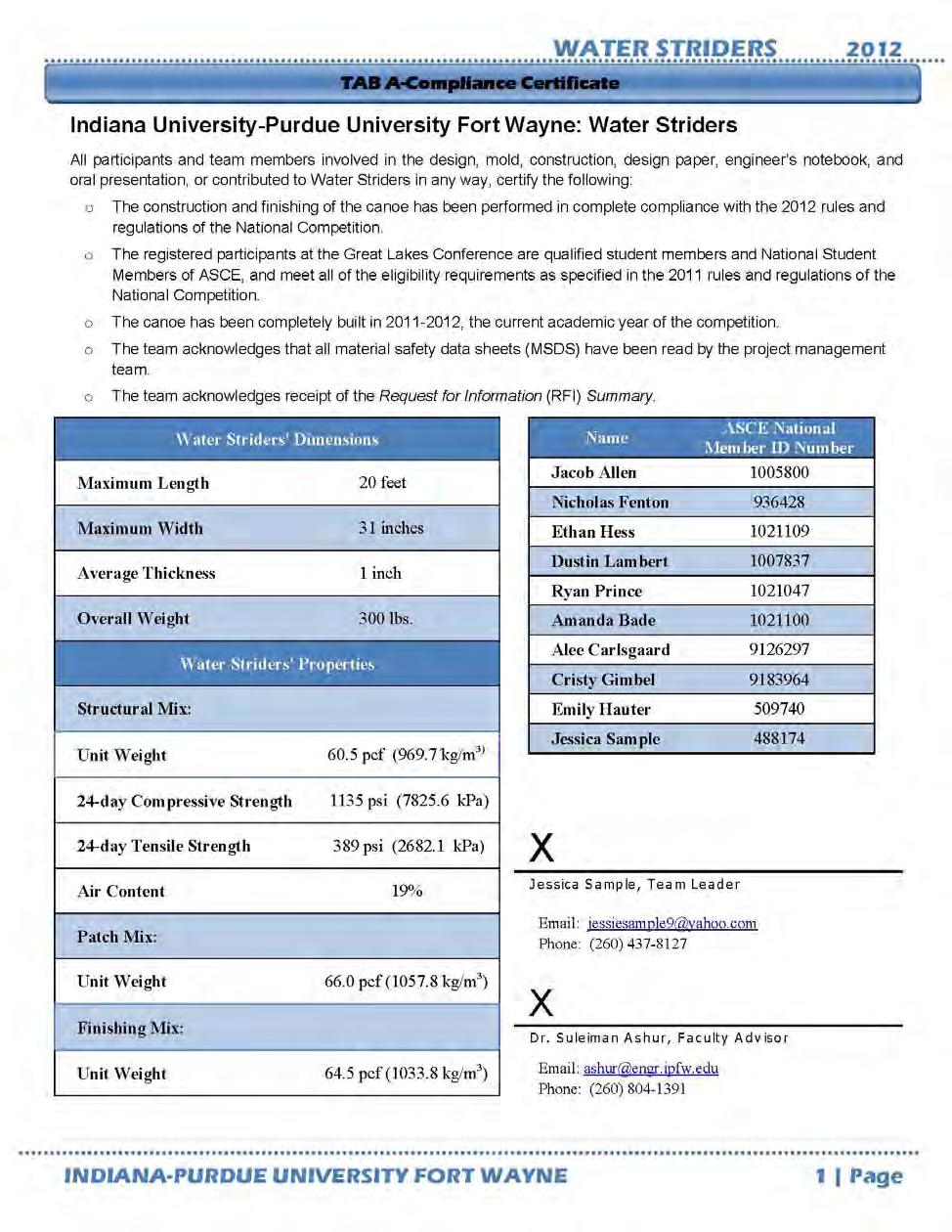
1
2 Table of Contents Acknowledgements... 4 Abstract... 4 Introduction... 5 Problem Statement... 5 Background... 6 Scope... 6 Spring Semester Goals... 7 Project Breakdown... 7 Constraints and Limitations... 7 Rules and Regulations... 7 Parametric Study... 8 Mold Construction... 9 Phase 1: AutoCAD Patterns... 9 Phase 2: Base Construction Phase 3: Skeleton Construction Exterior mold Interior Mold Phase 4: Mold Surface Exterior Mold Interior Mold Phase 5: Surface Finishing Phase 6: Creating the Graphics Casting Canoe Preparation Casting Curing Mold Removal Finishing Other Project Deliverables Concrete Canoe Design Report... 26
3 Oral Presentation Final Product Display The Races ASCE State Section Meeting Mobilization Product Performance Conclusions on Final Design Appendix A Appendix B Appendix C Appendix D Appendix E
4 Acknowledgements The senior design team would again like to acknowledge and thank a few businesses and individuals that aided in the construction of the concrete canoe. First, and foremost, the design team would like to thank Dr. Mohammed Alhassan for his assistance, guidance, knowledge, and encouragement throughout Semester II of Senior Design. Dr. Alhassan provided continuous direction regarding the entire design and build of the project. Dr. Suleiman Ashur, the coadvisor, also provided advice and support, as well as being the mediator between the American Society of Civil Engineers (ASCE) student organization and the senior design team. We would also like to thank Mark Mackenzie, the Quality Control Plant Manager at Erie Haven, for his knowledge and guidance regarding materials to be used in the concrete mix designs, as well as providing contacts for various companies. There are also several students that assisted in the concrete canoe casting, and de-molding of the canoe: Ryan Prince, Zach Estes, Nicholas Fenton, and Dustin Lambert. Also, a concrete canoe team was established to race the canoe at competition. The canoe team consisted of: Jacob Allen, Nicholas Fenton, Ethan Hess, Dustin Lambert, Ryan Prince, Amanda Bade, Alee Carlsgaard, Cristy Gimbel, Emily Hauter, and Jessica Sample. The design team is so grateful for the help and assistance of these individuals. There were also several companies that donated materials or monetary values this semester that were essential to completing the mold construction, canoe construction, transportation of the canoe, and competing in the 2012 Great Lakes Conference. The companies that donated materials or monetary values were Lafarge, GRACE Construction Products, Haydite, Speedway Redi Mix, Direct Colors, American Structurepoint, I-69 Trailer, Engineering Resources, and Three Rivers Running Company. The full list of companies and the material(s) they donated can be found in Appendix A. Without the help, assistance, guidance, and/or donation from these individuals and companies, the concrete canoe would have been much more challenging, if possible at all. Abstract As the Indiana-Purdue University Fort Wayne (IPFW) student chapter of American Society of Civil Engineers (ASCE) continues to grow, so does the desire to participate in civil engineering conferences. This year, the IPFW ASCE student chapter proposed that the senior civil engineering students design, test, and build a concrete canoe for the Concrete Canoe competition at the Regional ASCE Student Chapter Conference. This conference allows the civil engineering students at IPFW to be recognized for their engineering abilities compared to the other engineering schools around the nation. The 2012 concrete canoe was chosen as a senior design project to establish a strong foundation for future civil engineering students to design, build, and compete successfully in ASCE competitions.
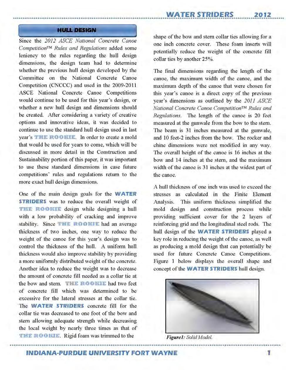
5 The first semester of the year (Fall 2011) was dedicated to the analysis and design of the concrete canoe, and establishing the schedule and budget to create a successful canoe in the time required. The second semester of the year (Spring 2012) was devoted to executing the canoe design to produce the final product to compete in the ASCE Student Chapter Conference. To create the final product, various steps were involved: building the wood interior and exterior mold, casting the canoe, finishing, establishing a transportation plan, and preparing for all the competition requirements. The canoe competition involved a final product display, racing the canoe, a design paper, and an oral presentation. IPFW competed successfully on April 20, 2012 against other engineering schools in the Midwest area and achieved impressive results in all of the canoe competitions. Introduction Problem Statement Since the early 1970 s the student organizations of American Society of Civil Engineers (ASCE) have conducted the concrete canoe competition. In the fall of 2010, the IPFW student chapter of ASCE decided to enter their first concrete canoe competition in the spring of This school year, the senior design team will tackle designing and building the canoe for the competition in the spring of In order to design and produce a successful concrete canoe for competition, the senior design team had to review and interpret the rules and regulations as stated in the 2012 ASCE National Concrete Canoe Competition Rules and Regulations. According to the rules and regulations of the competition, the development of the canoe can be broken down into these four categories: analysis, development and testing, project management and construction, and innovation and sustainability. In the first semester, the canoe design was analyzed for buoyancy and strength. The concrete mix designs were tested to meet the specifications according to the competition. Team members explored new options in sustainable materials required for the concrete mix design. In the spring semester, senior design team learned leadership skills, along with practical experience in project management and construction. The newest technologies and innovative ideas were implemented in the construction of the canoe whenever possible, and the design team explored various alternatives and developed a transportation plan for the canoe. The completion of the concrete canoe included various aspects of civil engineering and involved a combination of management, construction, concrete design, environmental topics, communication, and transportation of the final product.
6 Background For years, universities from around the world have competed in designing, building and racing concrete canoes. The first ASCE national canoe competition occurred in 1988, and 22 years later, the IPFW ASCE student chapter participated in their first competition at the University of Wisconsin-Milwaukee in Spring of Each year ASCE comes out with new rules and regulations to make the competition more challenging and to ensure previous canoe designs are altered. Dimensions, concrete mix design variables and percentage of sustainable materials are some of the factors that can be varied from year to year. Despite some complications with the concrete canoe, the experience provided a good foundation for the IPFW concrete canoe design. Considering this is a competition, the design team analyzed the winning aspects from the top performing canoes from previous years. Scope As defined in the Design of a Concrete Canoe for the 2012 ASCE Student Conference, the scope of the entire project was as follows: 1. The canoe will be delivered to the host s place of competition in April of Funding will be provided by IPFW ASCE, not by the canoe build and design team. 3. Finite Element Analysis (FEA) and hand calculations will be done before mold design can be finalized. 4. FEA will determine stress and displacements on canoe. 5. Mold design will meet required dimensions as specified in the rules. 6. Mold will be designed and built for ease of casting and de-molding. 7. Mold will be created in such a way that it is transportable to competition. 8. Concrete mix design will meet all criteria as set out in the rules. 9. Several mix designs will be tested before construction of canoe to find the optimal design. 10. Concrete mix designs will use sustainable materials when possible. 11. Transport canoe to competition without compromising the integrity of the canoe.
7 Spring Semester Goals To construct the canoe for the 2012 ASCE Great Lakes Conference, the design team had to establish a list of goals to be completed in the 2012 Spring Semester. The goals for this semester were as follows: 1. Build the concrete canoe according to the design established in the Fall Semester, as defined in Design of a Concrete Canoe for the 2012 ASCE Student Conference. 2. Transport the canoe safely from Fort Wayne, Indiana to the 2012 Great Lakes Conference held at Bradley University in Peoria, Illinois. 3. Compete successfully at the 2012 Great Lakes Conference. Project Breakdown Since the 2011 Fall Semester was dedicated to the design of the concrete canoe, the 2012 Spring Semester was devoted to constructing the canoe according to the design. The design of the canoe was divided into four main tasks: finite element analysis (FEA), concrete mix design, mold design, and construction management. To achieve the Spring Semester goals as stated above, a parametric study was done to optimize the thickness of the canoe before construction. The construction of the canoe involved various tasks: mold construction, casting the canoe, removing the mold, finishing the canoe, preparing for competition, transporting the canoe, and competing in the 2012 ASCE Great Lakes Conference. Each member of the senior design team was actively involved in completing these tasks. Constraints and Limitations Rules and Regulations The 2012 Rules and Regulations contain over sixty pages of competition parameters, with thirteen sections specifically outlining each significant segment of the competition. The thirteen sections are defined as follows: 1. General Rules and Regulations: provides a summary of what each school must do to be qualified and general information about the competition. 2. Canoe: provides the specification for the canoe to be built, such as dimensions, structural materials that can be used, and defining which canoes will be allowed to race. 3. Concrete: provides specification for the concrete mix design. This section was used in developing the concrete mix design. 4. Reinforcement: provides specifications for the various materials that be used as reinforcement, as well as the percent open-area allowed for the reinforcement. 5. Finishing: provides the specifications for the various materials that may be used to finish the surface of the canoe.
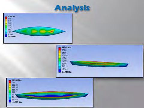
8 6. Design Paper: determines the topics that must covered in the design paper, such as concrete and composite development and testing, project management, innovations and sustainable aspects of the design. 7. Engineer s Notebook: intended to serve as a technical document, which contains the supportive information for the design and construction of the canoe. 8. Oral Presentation: contains the details for presentation to be given at the host school during the conference. 9. Final Product (Canoe and Cutaway Section): describes the various aspects of the Final Product judging and to provide guidance to the judges on the criteria for the assessment. 10. Product Display: provides the details as to limitations on how to set up the display featuring the tabletop display, concrete cylinder(s), sample(s) of concrete aggregate(s), seat and/or mats, and the Engineer s Notebook. 11. Race Rules and Regulations: this provides a guideline as to how the races will be conducted, including the rules of the races. 12. National Qualifying Rules: allows for teams that would like to be eligible to participate at the national level to follow the nation rules. 13. Overall Scoring: provides the scoring breakdown and how the scoring will take place. For the full set of the 2012 ASCE National Concrete Canoe Competition Rules and Regulations, please visit: Parametric Study Additional finite element analysis was conducted to determine the most optimal and economical thickness for the canoe. Finite element analysis to determine the stress within the canoe can be found in the Fall Semester senior design team s paper: Design of a Concrete Canoe for the 2012 ASCE Student Conference. From that analysis, case 2 was found to be the most critical case because it had the highest tensile stresses. This case consisted of 4 people in the canoe, weighing 200 pounds each, and the water pressure up to the rim of the canoe. It was found that the maximum principle tensile stress was 51 psi. To determine the most optimal and economical thickness for the canoe; a parametric study was conducted. The parametric study used the same forces as in case 2, but increased the thickness from 1 to 2 and decreased the thickness from 1 to ½. All the forces remained constant throughout the parametric study. The maximum principle tensile stress was recorded for each thickness analyzed. The maximum tensile stress is the most critical stress because concrete is weakest under tension so the maximum tensile stress was controlling. The results can be seen in Figure 1.
9 Maximum Tensile Stress (psi) Tensile Stress versus Canoe Thickness Canoe Thickness (in) Figure 1: Parametric Study. The results found that the 1 thickness was both optimal and economical for the concrete canoe. If the thickness was increased the maximum principle tensile stress would not decrease by very much (change in stress from 1 to 2 was a 20 psi decrease). When the thickness decreased, the maximum principle tensile stress would increase exponentially (change in stress from 1 to ½ was a 320 psi increase). The 1 thickness was the most optimal and economical because it is using the least amount of concrete, and has a low maximum tensile principle stress. Mold Construction The mold construction for the spring 2012 concrete canoe began as soon as finals were over during the Fall 2011 semester. Since the design was finalized, the materials would need to be estimated and then purchased. The primary materials used in the construction of the mold were medium density fiberboard (MDF), dimensional lumber (2x4), 5mm hardwood plywood. The mold construction was broken down into six phases: 1) Drawing AutoCAD patterns 2) Base Construction 3) Skeleton construction 4) creating the surface of the mold 5) surface finishing and 6) creating the graphics. Phase 1: AutoCAD Patterns The first phase of the mold construction was to draw the interior and exterior cross sections using AutoCAD in order to create patterns to be printed off and cut out. These patterns were drawn at one foot increment cross sections using AutoCAD and then they were printed off at a 1:1 scale. The exterior cross sections used from last year s specifications were easy to

10 manipulate, creating the necessary patterns. The interior mold cross sections were simply the dimensions of the exterior that have been offset by one inch for the thickness of the hull plus 5mm for the thickness of the plywood. After each pattern was printed and cut out of the paper, the corresponding interior and exterior cross section patterns were compared to each other to ensure correct hull thickness at each respected one foot increment along the length of the skeleton. Once this process was complete, the second phase of the mold construction could begin. This process can be seen below in Figure 2. Figure 2: Patterns drawn in AutoCAD. Phase 2: Base Construction A strong base to support both the mold and the canoe during casting and/or curing would need to be constructed to ensure the mold does not flex much and the complete structure can be moved around if needed since other people will be using the laboratory space during our canoe construction phase. The base was divided into four sections along the length that correspond to the length of each section that the mold will be divided into. The middle two base sections are each six feet long while the two end sections are five feet long. The overall width of the base is four feet and the base top sits approximately 22 inches from the floor. Each of the sections was created in the same manor. The four legs of the section were made out of 4x4 dimensional lumbers. 2x4 s connected each of the legs at both the top and bottom of each leg for lateral stability. Four inch wheels were purchased to allow each base section to roll. These wheels were mounted to the bottom of each leg. MDF was used as the base top and was
11 simply cut to fit the top. During casting, the mold will be joined together with mechanical fasteners through the 2x4 s that face each other of each section. As base sections are completed, the sections of the exterior mold could begin fabrication to reduce time and to maximize labor usage. The base can be seen in Figure 3, along with the skeleton of the canoe. Phase 3: Skeleton Construction Exterior mold The patterns created on AutoCAD were arranged onto the MDF for the purposes of maximizing the wood usage, reducing the waste and minimizing the cost. All of the patterns for both the interior and exterior were labeled to reduce the confusion as to which side of the canoe hull each section belongs. Each pattern was then traced onto the MDF and then each pattern was cut out of the MDF. All of the pieces cut out of the MDF had specific dimensions and belonged to a specific part of the mold. The combination of all of the MDF pieces would make up the skeleton of the mold. Each section of the base would be a platform for two of the mold section since the mold (base on the design) would be able to separate down its length. Therefore, two pieces of MDF was cut so that when combined, they would be the same size as each base section. Each of the skeleton pieces would be arranged to their respected position and place onto each respected mold section. Each of the skeleton pieces would be fixed to each mold section with drywall screws, glue and reinforces with more pieces of MDF in each corner of each skeleton piece. There was a piece of MDF that would be cut (created on AutoCAD, pattern cut out) to fit the top, leading exterior edge of the canoe. Every single exterior mold section was created in the same manor. Throughout this process, all of the sections must be checked to ensure that the entire structure is in alignment. Interior Mold After the patterns were cut out of the MDF, they were arranged in order by their respected position. Since the interior mold was separated into six, equally-spaced section of three feet, each skeleton piece was fixed to a three feet long, six inch wide piece of MDF. Lateral supports were cut and fixed to each skeleton section. 2x4 s were cut approximately three feet in length and mounted to the MDF three foot lengths and will be used as handles or lifting points for each section. All of the sections must be checked to ensure that the entire structure is in alignment.

12 Phase 4: Mold Surface Figure 3: Skeleton of canoe being constructed on top of base. Exterior Mold Applying the plywood surface was the most difficult part of this construction process. All of the 5mm plywood was cut to two feet wide sections, and then soaked in water for a minimum of 24 hours. After the wood was saturated, the wood was measured as to where the wood would begin to bend as it is pressed into the curvature of the skeleton. Once the measurements were taken, the wood was scored using a carpenter s knife approximately half the depth of the thickness. Each plywood section was then pressed into place, and then nailed down with pneumatic brad gun. Each piece of plywood was then trimmed to the edge of the mold. Some sections may need to be patched with more plywood due to the effects of trying to bend a two dimensional surface into a three dimensional shape. Once each section is completed and all patches have been made, the final phase is ready to begin. Throughout this process, all of the sections must be checked to ensure that the entire structure is in alignment. Interior Mold Through trial and error, it was determined that the best way to wrap each interior mold section with the plywood is do it in three pieces. Two of these pieces would start at the top edge of each interior mold section and be wrapped to the curvature of the mold section. The third

13 piece would be cut to join each side of the mold section from the curved surfaces. Each of the three pieces should be reinforced from the inside to ensure these pieces do not separate or shift during casting. This process is repeated for all interior mold sections. The applying of the plywood can be seen in Figure 4. Figure 4: Applying the soaked plywood to the canoe skeleton. Phase 5: Surface Finishing Finishing the surface of the mold was the same for all of the interior and exterior sections. This process began by aligning all of the sections together for both the interior mold and the exterior mold. All of the mold sections were fastened together and then marked to show how each section lines up to each other. Joint compound was applied to the plywood of both the interior mold and exterior mold, filling in any gaps, cracks, nail holes or any other imperfections. All of the surfaces were sanded until the desired quality had been achieved, as seen in Figure 5. Finally, the plywood was coated with spray adhesive and be allowed to become tacky. A thin layer of plastic (saran wrap) was applied to the surface to give a final, finished surface to the exterior of the canoe as well as ease the de-molding process, and can be seen in Figure 6.


14 Figure 4: Sanding the wood with the joint compound applied. Figure 5: Thin layer of plastic applied to the exterior mold.

 and 4) a water strider on the inside floor of the canoe. After each graphic was cut out of the vinyl, it was nailed to the mold using a pneumatic nail gun.")
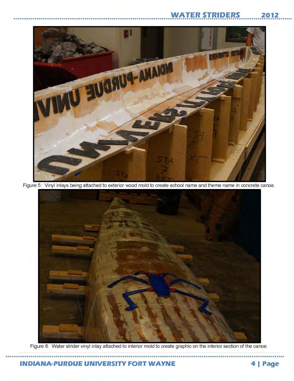
15 Phase 6: Creating the Graphics The graphics were created by mounting vinyl inlays to either the interior mold or the exterior mold depending on the specified location of the graphic. The graphics included with this year s canoe design are 1) large blue eyes at the bow 2) the name of our school spelled out completely 3) the name of this year s canoe (Water Strider) and 4) a water strider on the inside floor of the canoe. After each graphic was cut out of the vinyl, it was nailed to the mold using a pneumatic nail gun. Figures 7 and 8 show the vinyl inlays process. Figure 7: The water strider inlay being cut out of vinyl. Figure 8: The vinyl inlays for the school name and canoe name being attached.
 functioned as one unit. The interior mold needed to be reinforced from the top by connecting all sections with 2x4 s that ran the length.")
16 Casting Canoe Preparation In preparation for casting the canoe, both the interior and exterior mold sections were inspected to ensure that all sections were mechanically fastened together so than each mold (interior and exterior) functioned as one unit. The interior mold needed to be reinforced from the top by connecting all sections with 2x4 s that ran the length. The exterior mold sections were screwed to each other, then to the base so the mold would not move. All of the seams between each mold section (both exterior and interior molds) were filled in with joint compound or putty then covered with plastic so concrete would not leak out between sections. To finalize the mold preparation, the interior and the exterior mold sections were wiped down with a vegetable oil to ensure the concrete would not bond to the mold. All of the reinforcing was pre-cut prior to casting so the time that it took for placement of the reinforcing was minimized. For this year s canoe design, two layers of fiberglass reinforcing mesh were used along with five rows of longitudinal steel reinforcing rods (1/8 inch thick). The reinforcing mesh was dropped in perpendicular to the length of the canoe and cut so that a few inched of the mess was exposed, so that the mesh could be pulled up during pouring after the interior mold had been bolted into place. Each of the reinforcing mesh sections overlapped six inches in any direction. The steel reinforcing rods were measured, trimmed and wire-tied together so that placement would be quick and easy. To ensure there was at least a 1/8 inch amount of concrete covering the reinforcing mesh and steel rods, some steel chairs were crafted out of the steel ties and bent so that when the reinforcing mesh is placed on the chairs, the mesh will sit a minimum of 1/8 inch from the surface of the exterior mold, as seen in Figure 9. Figure 9: Steel chairs placed in mold.

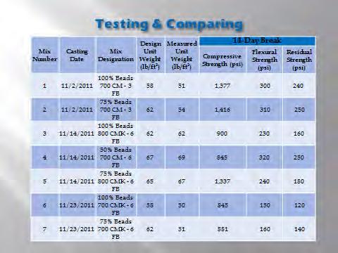
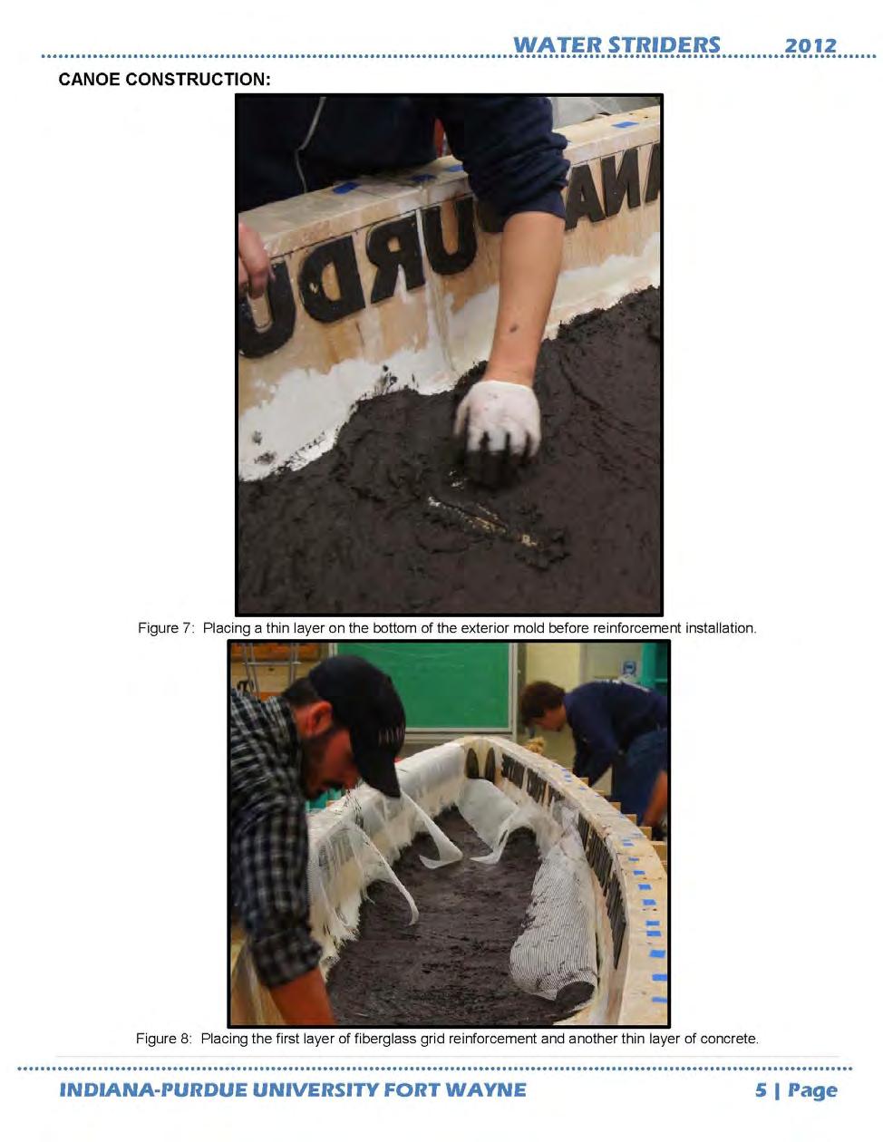
17 The interior mold section was 18 feet long while the exterior mold section was 20 feet long, leaving a one foot solid hull at both the bow and stern. There needed to be some extra concrete in these two areas of the hull, but this amount was too much. To reduce the amount of concrete needed for these two sections of the hull, each end was filled in with rigid foam that was cut in a way to maintain a one inch concrete cover. This foam was to be inserted after the interior mold section was fitted into place during casting and while the concrete was being poured up the sides, between the interior and exterior molds. Casting After each of the concrete batches was mixed, test cylinders, beams and unit weight measurements were taken for quality assurance. At one and a quarter cubic feet per batch, the number of batches required was estimated to be five which was to include the concrete for the test cylinders and beams as well as the entire canoe. The amount of concrete estimated to finish the canoe was around five cubic feet with an average of around 60 pounds per cubic foot unit weight which means that the canoe was estimated to weigh around 300 pounds. After the tests were completed for each batch, the concrete was poured into the exterior mold until the concrete covered the reinforcing chairs completely at which point the first layer of reinforcing mesh was placed and then pressed down so that concrete seeped through the holes of the mesh. Then, more concrete was poured into the mold until another 1.8 inch of concrete covered the first layer of reinforcing mesh. The reinforcing rods were then placed into the concrete on top of the mesh. The reinforcing rods were basically sandwiched between the two layers of the reinforcing mesh. After the steel rods were dropped into place, the final layer of reinforcing mesh was placed. Concrete was then spread over the mesh while working the concrete through the holes of the mesh to ensure that there would not be any voids around the reinforcing layers. Figures 10 and 11 show this process. Figure 10: First layer of concrete being placed.

18 Figure 11: Reinforcing fiberglass mesh being added, along with steel bars. After all of the reinforcing was placed, concrete was continuously poured into the mold until the depth of the concrete at the bottom of the mold achieved a minimum of one inch but not more than 1-1/8 inch. Concrete was casted up each side of the exterior mold until the concrete began to settle. The interior mold was then lifted and set into place. The alignment of the interior mold relative to the exterior mold was checked to be sure it was in position from the side and down the length. When the interior mold was verified that it was correctly aligned, the interior mold should be bolted to the exterior mold so that the interior mold would not shift during the remainder of the casting process. After the interior and exterior molds were joined, the casting continued by pouring the concrete in between the mold sections. To aid in consolidation, a concrete vibrator was placed on top of the interior mold structure. Tapping the sides of the exterior mold and churning the concrete also helped to consolidate the concrete. Regardless of the efforts, some voids in the canoe hull were expected due to the design of the mold. The concrete was poured into the mold until the concrete reached the top of both of the molds (the top of the mold was used as a reference point which was the actual top edge of the canoe). As the bow and stern ends were filled up with concrete, the foam pieces that were pre-cut were simply pushed into place and then concrete was filled around them. After the concrete was poured to the top edge of the canoe, the concrete was smoothed out with a trowel. This concludes the casting of the canoe, but other steps were taken to ensure proper curing of the canoe. Figures 12, 13, and 14 explain this process.


19 Figure 12: The interior mold being attached to the exterior mold. Figure 13: Pouring concrete down the sides of the molds.

20 Figure 14: Rigid foam wedge being placed in the bow. Curing While the concrete cured inside the mold, wet burlap was placed on any exposed surface (to the air) and plastic was laid over the burlap. The concrete was cured for a minimum of 14 days before the removal of the interior mold to ensure proper strength. After the interior mold was removed, wet burlap was again placed on any exposed surface with plastic on top of the burlap. The canoe was cured for a minimum of 28 days before the canoe was removed from the mold completely since concrete typically achieves the majority of its strength after this amount of curing time has lapsed. After the canoe was completely removed from the mold, further curing was not deemed necessary. Mold Removal As previously stated, the interior mold was removed fourteen days after the pour. The stern portion of the mold was disassembled in an effort to allow for easy removal of the five other interior mold sections. The sections were pulled vertically out after the handles were cut into the sections. Once the entire interior mold was removed, wetted burlap and plastic were once again placed back over the canoe to continue in the curing process. Twenty-eight days after the pour, the exterior mold sections were removed with the help of our faculty advisors and a few ASCE student chapter members. Despite covering the mold in a layer of vegetable oil, the canoe seemed to be stuck to the walls of the mold. A crow bar was needed in order to separate the mold sections and the canoe enough that people could pull them apart with their hands. The two bow sections were removed first without any damaged to the mold


21 pieces or the canoe. The problem was discovered that the inlays were not pulling out of the walls of the canoe. Since the inlays had been nailed to the wall of the mold the team had to separate the mold from the nails and inlays. The team used the crow bar once again to start the careful separation of canoe from mold. The base pieces of the mold broke due to the lack of strength of the wood used in the construction. It was determined in order to safely de-mold the canoe the mold would need to be disassembled. The skeleton pieces were removed to allow for the wood skin to be peeled back from the canoe. During the whole mold removal, the team was careful to not put any forces on the canoe, that would cause it to crack or break. The canoe was placed on two mattresses with the bow and stern supported by blocks of high density foam. Figures 15 and 16 display the mold removal. Figure 15: Starting to de-mold with crow bar. Figure 16: Removing the exterior mold from the canoe.

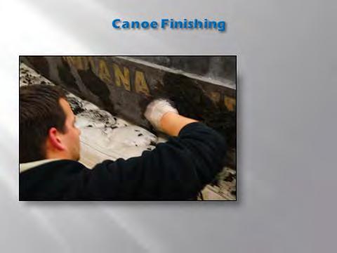
22 Finishing The first step in finishing the canoe was to fill in any voids that were present on the interior of the canoe with a patch mix. Once the patch mix had cured for 7 days the team rough sanded the interior of the canoe with 80 grit sand paper. The canoe was flipped to expose the whole exterior and the process was repeated. The vinyl inlays were carefully removed from the canoe. The edges of the inlays were cleaned up using a dremel tool. A white concrete inlay mix was placed into all of the inlays. After 7 days, the canoe was rough sanded a second time, with 150 grit sand paper, to even out the new inlays with the rest of the canoe. The team then spread a black slurry mix all over the canoe to fill in any small voids that presented themselves during the rough sanding step. The team wet sanded with 220 grit sand paper over the entire canoe to give the surface a very smooth feel. The eyes and the water strider were painted with a blue concrete stain. The letters for the school and canoe name were first painted black and then outlined in white using epoxy concrete paint. The canoe had the black concrete stain painted on it to allow for a uniform black color. Finally, the design team applied a clear coat on the canoe to give the concrete canoe a shiny, finished look. Figures 17 through 23 display the different finishing stages. Figure 17: The design team with the unfinished canoe.


23 Figure 18: The patch mix being applied where needed. Figure 19: The design team starting to rough sand the canoe.


24 Figure 20: The design team wet-sanding the canoe. Figure 21: Applying the blue stain to the water strider graphic.


25 Figure 22: Applying the concrete paint to the lettering. Figure 23: The final canoe product with two coats of the clear sealer applied.
26 Other Project Deliverables The concrete canoe competition involved not only designing and building a concrete canoe, but various other aspects. The competition was judged on four main categories: a design report, an oral presentation, final product display, and the races. The senior design team also presented the concrete canoe design at the 2012 ASCE State Section Meeting. Concrete Canoe Design Report As explained previously, the design report was one of the four main categories that the competition was judged upon. It was worth 25% of the overall competition, and therefore it was imperative to complete this design report according to the specifications as laid out in the 2012 ASCE NCCC Rules and Regulations. The design report was to cover various areas related to the design and construction of the concrete canoe such as the concrete and composite development and testing, project management, innovations and sustainable aspects. The design report had to be mailed and received by the judges no later than March 1, The design team worked on the paper collectively to complete the report requirements, as well as send it to the judges by the deadline. The design report had an extremely stringent format to follow, and had to contain the following sections: report cover, table of contents, executive summary, hull design, structural analysis, development and testing, construction, project management, sustainability, organization chart, project schedule, design drawing, references, mixture proportions, and a bill of materials. The final 2012 IPFW Design Report is attached to Appendix B. Oral Presentation The oral presentation was the second category in the overall canoe competition, and was also worth 25% of the scoring. The oral presentation was a live, five minute technical presentation highlighting the various aspects of the project followed by a seven minute question and answer period with the judges. The oral presentation gave the design team the opportunity to explain to the judges, in person, the design concept and construction process. The final 2012 IPFW Oral Presentation is attached in Appendix C. Figure 24 shows Amanda and Jacob giving the oral presentation at Conference.

27 Figure 24: Amanda Bade and Jacob Allen giving the oral presentation at Conference. Final Product Display The final product display contained various parts, and also contributed to 25% of the overall scoring. It involved not only the displaying the final concrete canoe product, but also setting up a tabletop display, creating a cutaway section to explain the construction process, and completing an Engineer s Notebook that contained pictures of the construction process, and standards for the materials used in the concrete canoe. At competition, the judges base part of the final product display scoring on aesthetics. The concrete canoes were all assembled in a common area, and placed on display stands. The senior design team asked IPFW ASCE student members to take the lead on building the display stand for the canoe. Nicholas Fenton, the ASCE student chapter president built the canoe display based on this year s canoe theme: Water Striders. Figure 25 below, shows the final canoe product display, to look like a Water Strider.


28 Figure 25: Final Product Display. The product display also included a tabletop display which was to include concrete cylinders of the different mixes used in the canoe construction, samples of the concrete aggregates, samples of the reinforcement used in the canoe, a poster display conveying information in the design paper such as photographs and charts, a cutaway section of the canoe, and the Engineer s Notebook. Figure 26 shows the tabletop display, and Figure 27 shows the cutaway section. The cutaway section of the canoe was a three-foot section serving as a representative of both the raw and finished canoe. It was created to show concrete placement, finishing of the canoe at various stages, and display how the interior and exterior mold created the desired shape of the bow and also achieve the consistent one-inch thickness. Figure 26: Tabletop display.

29 Figure 27: Cutaway section. The Engineer s Notebook, as displayed in Figure 26 on the tabletop display, was a technical document which contained supportive information related to the design and construction of the canoe. It also included a compliance certificate to ensure the registered participants of the canoe team met all eligibility requirements. The Engineer s Notebook also followed a strict format, and contained the following sections: Table of Contents, Compliance Certificate, Construction Photographs including mold construction, canoe construction and finishing the canoe, Hull Thickness/Reinforcement and Percent Open Area Calculations, and Material Technical Data Sheets of all the materials used in the concrete canoe final product. The final 2012 IPFW Engineer s Notebook is attached in Appendix D. The Races The final 25% of the canoe competition scoring came from racing the canoe. The races involved five different competitions: a men s endurance, a women s endurance, a men s sprint, a women s sprint, and finally, a coed sprint. The IPFW canoe racing team consisted of ten of the IPFW ASCE Student Chapter members, including three from the senior design team: Amanda Bade, Jacob Allen, and Jessica Sample. The canoe racing team started practicing for the races in early February right up until the week before Conference. Practices involved either working at out the IPFW Student Athletic Center, or taking canoe up to Blue Lake, in Churubusco, Indiana, as seen in Figure 28.


30 Figure 28: Practicing rowing at Blue Lake. The endurance races at the competition consisted of either two men or two women and a 600 meter course. The men s sprint and women s sprint involved either two men or two women and a 200 meter course. The coed sprint race included two men and two women and a 400 meter course. The races were competed against other schools in the conference. Figure 29 below shows the coed race. Figure 29: The coed race at Conference.
31 ASCE State Section Meeting As previously discussed, the concrete canoe design was presented at the annual ASCE State Section meeting held in Carmel, Indiana. Every year, the ASCE holds a meeting for all the ASCE members in Indiana, and the meeting includes lunch, awards, and presentations by senior design teams from various Indiana Engineering Schools. As a way to prepare for the Concrete Canoe Competition, two members of the senior design team, Jacob Allen and Jessica Sample, participated in the senior design competition. Every senior design team that presented received a one hundred dollar check for their ASCE Student Chapter Organization, while the winning senior design team won a plaque. Although the IPFW senior design team did not win the competition, the canoe design presentation was complimented and the hard work of the team was acknowledged. The presentation given was the same presentation given at Conference, and is attached in Appendix C. A handout was passed around to explain the four different the categories the competition was judged on, and is attached in Appendix E. Mobilization The team also had to develop a way to transport the canoe safely to the conference. The canoe was transported in a trailer. The team decided to create a box with padding that the canoe could sit in. The padding was essential because it had to absorb any vibrations caused by the vehicle or imperfections in the roads, during transit. Any vibrations would cause stress in the canoe and if the stress became too great it would crack the canoe. The box was designed to both hold the canoe in the trailer, and to make it easy to move the canoe. The box was constructed out of particle board, 2 x 4 boards, 2 x 6 boards, and screws. Particle board was used as the base of the box and the 2 x 4 boards were used as reinforcement under the particle board. Then the 2 x 6 boards were placed around the perimeter on the top to create a lip so the canoe doesn t slide off. It was constructed in three 7 section, giving a total length for the box to be 21. This allowed for a 4 clearance at either end, because the canoe is 20 in length. The width of the box was 42, giving a 3 clearance on either side of the canoe because the canoe is 36. Six handles were placed on both sides of the box in order to create an easy way to lift the box to move the box with the canoe in it. These handles were made out of nylon rope and securely tied to prevent the rope from breaking loose. For the comfort of the people caring the box and canoe, the nylon rope was also thread through ¾ PVC pipe. A picture of the final transportation box can be found in Figure 30.

32 Figure 30: The canoe in the transportation box. Three different materials were used to help cushion the canoe in transit. Within the box, two materials were used. First, the box was lined with two layers of bubble wrap. Second, the box was lined with two layers of 9¼ fiberglass attic insulation. This was above the 6 lip from the 2 x 6 boards, but once the canoe was placed in the box, the canoe compressed the two layers of fiberglass attic insulation to 5. The canoe was set into the box upside down, as seen in Figure 30. The canoe was upside down because this will prevent the canoe from rocking from side to side, and the canoe would be stronger because the walls will form an arc. Most stress within an arc are compressive stress and concrete is much stronger in compression then tension. This will help prevent cracking during transit. The canoe in the box can be seen above in figure something. Two bed mattresses were placed under the box, in the trailer. Additional fiberglass attic insulation was added to areas around the box to insure the canoe would not move. Finally, the canoe was strapped down to the box in order to prevent the canoe from bouncing. This method provided much success. The canoe arrived at conference with no damage. Product Performance Once the canoe was transported to the Conference location, the concrete canoe team (as listed in the Acknowledgements) set up the final product display. The judges passed back the scores for the design papers. The design team received a perfect score, with no deductions. After the judges assessed the final product display, the race portion of the competition began. A swamp test was first conducted to be sure every school s concrete canoe floated. The swamp test consisted of putting the canoe in the lake, filling it with water, and allowing the judges to
33 observe the canoe float to the top. Following the swamp test, came the races in the following order: women s endurance, men s endurance, women s sprint, men s sprint, and coed sprint. The results from the races are as follows: 5 th in the Women s Endurance Race 5 th in the Men s Endurance Race 8 th in the Women s Sprint Race 6 th in the Men s Sprint Race 3 rd in the Coed Sprint Race The results of the canoe competition were not revealed until the Awards Ceremony of the Conference. The IPFW design team and concrete canoe team received the following: 3 rd Best Design Paper (with no deductions) 5 th Overall for the Concrete Canoe 3 rd Overall for the ASCE Conference The IPFW ASCE Student Chapter Members who attended the Great Lakes Conference were very proud of these accomplishments. The design and construction of the concrete canoe was an overall success, and the product performed as the senior design team expected. Conclusions on Final Design In conclusion, the team designed and created a successful final product for the 2012 ASCE National Concrete Canoe Competition Regional Conference held at Bradley University. The team built the mold according to the Fall 2011 design. The mold functioned as designed until it was to be removed. There were graphics stapled to the top of the mold that was not part of the design that when combined with the frictional force from the weight of the canoe, resulted in the team having to destroy the mold to remove it from the canoe. The casting of the canoe went smoothly and as planned. The finishing was reduced considerably from the previous year. The design paper was a complete success with zero deductions. The oral presentation successfully conveyed all the design team s design concepts to the judges. The final product display was impressive to say the least with a minor deduction from the table display. The outcome of the races was respectable for the first year racing in this competition. The design and construction of the concrete canoe was an overall success, and the product performed as the senior design team expected. Overall, this project was a success and this project set the bar high for future ASCE concrete canoe competitions for IPFW to participate in. To follow up on the concrete canoe as to how it was designed please refer to the Design Report of this project that was posted in December 2011 on the IPFW engineering website.
34 Appendix A
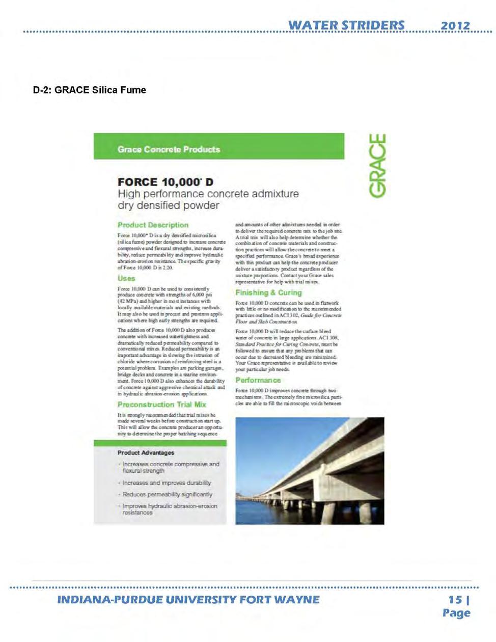
35 Table A.1: Companies and Donations. Company Donation(s) Lafarge Portland Cement GRACE Construction Products Reinforcing fibers, silica fume Haydite Lightweight aggregate-expanded shale Speedway Redi Mix Concrete Color Dye Directs Colors Concrete Stain American Structurepoint Monetary I-69 Trailer Trailer for Transport Engineering Resources Monetary Three Rivers Running Company Wetsuits
36 Appendix B
37

38

39
40

41

42

43
44

45

46

47
48

49

50
51

52
53

54

55
56 Appendix C

57

58


59

60


61


62

63


64


65

66


67
68 Appendix D
69
70
71

72

73
74
75
76

77

78

79
80
81
82
83
84
85
86
87

88

89
90
91
92
93
94
95
96
97
98
99
100
101
102
103
104
105
106
107
108
109 Appendix E

110
Soling Building Tips II
 Soling Building Tips II Prepared: Arthur Deane Jan 20, 2002 adeane@ic.net Introduction The following are some lessons learned and experience gained in building a Soling kit. The plan developed is based
2016 NAU ASCE CONCRETE CANOE POLARIS NORTHERN ARIZONA UNIVERSITY CHELSIE KEKAULA COLTON MCCONNELL BRENT LIPAR EVAN KAICHI EMILY MELKESIAN
 2016 NAU ASCE CONCRETE CANOE NORTHERN ARIZONA UNIVERSITY CHELSIE KEKAULA COLTON MCCONNELL BRENT LIPAR EVAN KAICHI EMILY MELKESIAN 1 Project Description Design and construct a concrete canoe Maximum length/width:
Cc: Bridget Bero, Ph.D., P.E., Wilbert Odem, Ph.D., P.E., and Alarick Reiboldt, EIT, CENE 486 Instructors
 To: Mark Lamer, P.E., CENE 486 Grading Instructor From: North Star Engineering: ASCE 2015-16 Concrete Canoe Team Date: January 25 th, 2016 Re: Technical Advising Meeting #1 Chelsie Kekaula Reinforcement
FLORIDA GULF COAST UNIVERSITY 2015
 FLORIDA GULF COAST UNIVERSITY 2015 60057 ENGINEER S NOTEBOOK TABLE OF CONTENTS TAB A: COMPLIANCE COMPLIANCE CERTIFICATE 1 ASCE NATIONAL MEMBER ID NUMBERS 1 TABLE 1: DIMENSIONS AND SPECIFICATIONS OF CANOE
LoneStar Fiberglass Pools. Do-It-Yourself. Installation Manual
 LoneStar Fiberglass Pools Do-It-Yourself Installation Manual Chris 1/3/2008 Do-It-Yourself The installation of a LoneStar Fiberglass pool is a much simpler task than most people think. What is important
Service Bulletin 70. Subject: Vertical fin cracks. Applicability: All Sportsman aircraft
 Subject: Vertical fin cracks Applicability: All aircraft Issue: Inspection of the vertical fin and aft fuselage bulkheads B and C, repair of vertical fin and bulkheads and reinforcement of vertical fin
CONQUEST Quick Facts Hull Design: Table of Contents
 Table of Contents Hull Design 1 Analysis 2 Development & Testing 3 Project Management & Construction 5 Organization Chart 7 Project Schedule 8 Design Drawings w/ Bill of Materials 9 Appendix A: References
EXECUTIVE SUMMARY. It s a Trap! The University of Michigan. consistently placed fourth or fifth overall at regional competition.
 TABLE OF CONTENTS Executive Summary. i Analysis 1 Development & Testing... 2 Project Management 3 Construction 4 Innovation and Sustainability.. 6 Organization Chart.. 7 Project Schedule.. 8 Design Drawing..
HCMTCB MATERIALS SAMPLING & TESTING PERFORMANCE CHECKLIST
 HCMTCB MATERIALS SAMPLING & TESTING PERFORMANCE CHECKLIST Release Date: January 7, 2014 Sampling Coarse Aggregate PERFORMANCE CHECKLIST AASHTO T-2 Sampling of Aggregates Sampling From A Stockpile 1 When
Tex-414-A, Air Content of Freshly Mixed Concrete by the Volumetric Method
 by the Volumetric Method Contents: Section 1 Overview...2 Section 2 Apparatus...3 Section 3 Sampling Requirements...5 Section 4 Procedures...6 Section 5 Calculation...9 Section 6 Archived Versions...10
An individual LEAP Response is required for this event and must be submitted at event check-in (see LEAP Program).
.") DRAGSTER OVERVIEW Participants design and produce a race-worthy CO 2 -powered dragster according to stated specifications, using only specified materials. Special design requirements will be posted for
DRAGSTER OVERVIEW Participants design and produce a race-worthy CO 2 -powered dragster according to stated specifications, using only specified materials. Special design requirements will be posted for
Trim Tab Wind Vane for boats with transom mounted rudders
 Trim Tab Wind Vane for boats with transom mounted rudders If your boat has a transom mounted rudder, you can build this self-steering windvane for around $150, using regular wood working tools and some
American Flagpole & Flag Co. 1(800)
") SENTRY CONCEALED HALYARD-REVOLVING TRUCK GROUND SET INSTALLATIONS INSTRUCTIONS 1. Dig foundation as detailed in SECTION A FOUNDATION SPECIFICATIONS, set sleeve in enter of hole with top 2 above grade.
SENTRY CONCEALED HALYARD-REVOLVING TRUCK GROUND SET INSTALLATIONS INSTRUCTIONS 1. Dig foundation as detailed in SECTION A FOUNDATION SPECIFICATIONS, set sleeve in enter of hole with top 2 above grade.
DIY Shallow Water Anchor Assembly Instructions for Rods, T-grips, Stainless Tips, Stainless Couplers, and the 4-in-1 Paddle
 DIY Shallow Water Anchor Assembly Instructions for Rods, T-grips, Stainless Tips, Stainless Couplers, and the 4-in-1 Paddle All Shallow Water Anchor Parts First, start by laying out and identifying all
A PRODUCT OF THE UNIVERSITY OF MICHIGAN CONCRETE CANOE TEAM
 A PRODUCT OF THE 2007-2008 UNIVERSITY OF MICHIGAN CONCRETE CANOE TEAM TABLE OF CONTENTS Report: Appendices: Executive Summary... i Hull Design... 1 Analysis... 2 Mix Development and Testing... 3 Project
Surfboard Repairs Chapter 7
 Surfboard Repairs Chapter 7 The Complete Surfing Guide for Coaches - Bruce "Snake" Gabrielson Repair Problems Boards continuously get bumped, hit rocks, break fins, get dropped, and many other things that
Pakboats PakCanoe Assembly Instructions
 Pakboats PakCanoe Assembly Instructions Note: Please read these assembly instructions carefully before assembling the canoe. a A. Assembling the canoe Note: Don't be afraid to get into the canoe while
DETERMINING OPTIMUM RESIDUAL ASPHALT CONTENT (RAC) FOR POLYMER-MODIFIED SLURRY SEAL (MICROSURFACING) MIXTURES
 FOR POLYMER-MODIFIED SLURRY SEAL (MICROSURFACING) MIXTURES") Test Procedure for DETERMINING OPTIMUM RESIDUAL ASPHALT CONTENT (RAC) FOR POLYMER-MODIFIED SLURRY SEAL (MICROSURFACING) MIXTURES TxDOT Designation: Tex-240-F Effective Date: December 2004 1. SCOPE 1.1
Test Procedure for DETERMINING OPTIMUM RESIDUAL ASPHALT CONTENT (RAC) FOR POLYMER-MODIFIED SLURRY SEAL (MICROSURFACING) MIXTURES TxDOT Designation: Tex-240-F Effective Date: December 2004 1. SCOPE 1.1
(Specification changes are highlighted in yellow)
") APPENDIX II SCRUTINEERING (Specification changes are highlighted in yellow) 101. ICF Canoe Polo Kayak Manufacturers Scheme 1.1. - After January 1 st 2015 - All new composite canoe polo kayaks manufactured
APPENDIX II SCRUTINEERING (Specification changes are highlighted in yellow) 101. ICF Canoe Polo Kayak Manufacturers Scheme 1.1. - After January 1 st 2015 - All new composite canoe polo kayaks manufactured
RESISTANCE OF COMPACTED ASPHALT MIXTURE TO MOISTURE INDUCED DAMAGE (Kansas Test Method KT-56)
") 5.9.56 RESISTANCE OF COMPACTED ASPHALT MIXTURE TO MOISTURE INDUCED DAMAGE (Kansas Test Method ) 1. SCOPE This test covers preparation of specimens and measurement of the change of tensile strength resulting
5.9.56 RESISTANCE OF COMPACTED ASPHALT MIXTURE TO MOISTURE INDUCED DAMAGE (Kansas Test Method ) 1. SCOPE This test covers preparation of specimens and measurement of the change of tensile strength resulting
1982 Hydrostream Viking Restoration
 1982 Hydrostream Viking Restoration Part 2c: The Rebuild Daniel W. Rickey Winnipeg, Manitoba Canada daniel@cancercare.mb.ca 2000-09-22 Introduction Part one of this report showed how the shoddy manufacturing
Method of Making and Curing Concrete Specimens in the Field for Compression and Flexural Tests
 Method of Making and Curing Concrete Specimens in the Field for Compression and Flexural Tests 1. Scope: This is the procedure for making and curing concrete specimens to be used for compression and flexural
FINALIZATION OF THE HAND DUG WELL. Version : April 2009 Published by : Foundation Connect International Autors : Henk Holtslag & John de Wolf
 ST 1.6 FINALIZATION OF THE HAND DUG WELL Version : April 2009 Published by : Foundation Connect International Autors : Henk Holtslag & John de Wolf Disclaimer This manual is part of the main manual, named
TEST FOR STABILOMETER VALUE OF BITUMINOUS MIXTURES
 Test Procedure for TEST FOR STABILOMETER VALUE OF BITUMINOUS MIXTURES TxDOT Designation: Tex-208-F Effective Date: February 2005 1. SCOPE 1.1 Use this test method to determine the Hveem stability value
Dornier Do R 4 Super-Wal
 Dornier Do R 4 Super-Wal Model Aviation Laddie Mikulasko s Dornier Do R 4 Super-Wal Build the multiengine, record-setting seaplane. Article, plans, instructions, and photos by Laddie Mikulasko. Complete
Vacuum Bagging Wings Instruction Manual Purdue University
 Vacuum Bagging Wings Instruction Manual Purdue University Note: Do not leave the vacuum pump running unattended! Revision: Original Release 10/31/15 Vacuum bagged wings are quick to build, light weight,
Puffin Sport Assembly and User Information
 Puffin Sport Assembly and User Information ScanSport, Inc. / Pakboats Post Office Box 700 May Street Enfield, New Hampshire 03748 USA Phone: (888) 863-9500 (toll free) From outside the US: +1 (603) 632-9500
Big Ride ASSEMBLY AND INSTALLATION INSTRUCTIONS * * C A U T I O N * *
 Big Ride ASSEMBLY AND INSTALLATION INSTRUCTIONS * * C A U T I O N * * S.R. SMITH BIG RIDE SLIDES ARE MANUFACTURED FOR INSTALLATION AND USE ON INGROUND SWIMMING POOLS ONLY. THE BIG RIDE IS NEVER TO BE INSTALLED
WHITE WOLF. X-ray View MID POWER MODEL ROCKET KIT BUILDING INSTRUCTIONS KIT SPECIFICATIONS:
 WHITEWOLF-38 PARTS LIST 1 - Nose Cone 1-17" Airframe 1-6" Motor Tube 3 - Aft Fins 3 - Forward Fins 2 - Centering Rings 1-15" Parachute 2 - launch lugs 1-12 Kevlar Shock Cord 1 - Motor Retention >>(screw/washer)
Trogear Bowsprit Through Hull Installation Manual
 Trogear Marine Products, LLC www.trogear.com info@trogear.com 866-616-2978 Trogear Bowsprit Through Hull Installation Manual Congratulations on your purchase of the Trogear Bowsprit which can be installed
NEW DESIGNS. Print in Landscape Mode with ¼ inch borders. Hinges (2) degrees. 1 Seating Type Optional
 degrees. 1 Seating Type Optional") 2017 IDEAS NEW DESIGNS Ken Simpson Designs Drawn 06-01-2017 Rev. 07-02-2017 The SPORTSMAN 10'L x 36 W x 15 H 475 pound Capacity Print in Landscape Mode with ¼ inch borders. Hinges (2) 36 30 8 degrees Click
2017 IDEAS NEW DESIGNS Ken Simpson Designs Drawn 06-01-2017 Rev. 07-02-2017 The SPORTSMAN 10'L x 36 W x 15 H 475 pound Capacity Print in Landscape Mode with ¼ inch borders. Hinges (2) 36 30 8 degrees Click
Team Insert Valve Sample Specification The Insert Valve shall conform to the following:
 Team Insert Valve Sample Specification The Insert Valve shall conform to the following: The Ductile Iron 250 p.s.i.g. Insert Valve shall be a Resilient Wedge Gate Valve designed for use in potable water,
NAVIGATOR PROP BUILDING INSTRUCTIONS & PHOTOS
 NAVIGATOR PROP BUILDING INSTRUCTIONS & PHOTOS Science under the ice Ice sheet At regional competitions the ice is simulated by 8 ft x 4 ft ½-inch foam sheeting (Home Depot part #703990 [in store only],
Table of. Contents. Appendices Appendix A: References... A-1 Appendix B: Mixture Proportions... B-1 Appendix C: Bill of Materials...
 Table of Contents Executive Summary... i Project Management... 1 Organizational Chart... 2 Hull and Structural Analysis... 3 Development and Testing... 4 Construction... 7 Project Schedule... 9 Design
OWNER S MANUAL ALWAYS WEAR A GOVERNMENT APPROVED FLOATATION DEVICE WHEN FISHING. Know the limits of your ability and the limits of your equipment.
 OWNER S MANUAL ALWAYS WEAR A GOVERNMENT APPROVED FLOATATION DEVICE WHEN FISHING. Know the limits of your ability and the limits of your equipment. Changes in air temperature and elevation could cause the
PETERSEN 161-SERIES HIGH PRESSURE LIFTING AIR BAGS OPERATING INSTRUCTIONS WARNING!
 PETERSEN 161-SERIES HIGH PRESSURE LIFTING AIR BAGS OPERATING INSTRUCTIONS WARNING! Read and understand instructions before using Petersen Plugs. Failure to comply may result in property damage, serious
SECTION 48 - TRAFFIC STRIPES AND PAVEMENT MARKINGS TABLE OF CONTENTS
 SECTION 48 - TRAFFIC STRIPES AND PAVEMENT MARKINGS TABLE OF CONTENTS Section Page 48-1 GENERAL...48.1 48-2 THERMOPLASTIC TRAFFIC STRIPES AND PAVEMENT MARKINGS...48.1 48-3 PAINTED TRAFFIC STRIPES AND PAVEMENT
IEEE Southeastcon 2014 Student Hardware Competition Rules
 IEEE Southeastcon 2014 Student Hardware Competition Rules I. Introduction In Kentucky, collegiate basketball is serious business and we d like to bring the thrill to you in a lighthearted competition.
Installation Instructions For Flat Seated Bolted Type RAH Series Disk Holders
 Installation Instructions For Flat Seated Bolted Type RAH Series Disk Holders RA Series Rupture Disks 1. WARNING a) Read the complete instructions before attempting to install the rupture disk and holder
Build a Milk Carton Boat for the
 Milk Carton Boat Building Guide - 2017 Build a Milk Carton Boat for the Here s How PICK A CATEGORY The Valleyfair Milk Carton Boat Race is divided into two boat categories. A boat can be used for only
34. Aft view of the boat at it s highest point.
 32. The repaired holes. Still looks pretty ugly, though maybe not quite as bad. The epoxy probably isn t strong enough to make any difference in strength, but you never know of a piece of masking tape.
other tables and stations. A plexiglass sheet was placed on a table top to provide the smooth flat surface to lay up the fiberglass on.
 Fiberglassing After hot wire cutting our four airfoils for testing, it was decided that greater strength was needed. The foam airfoils do not have the required strength to withstand the forces of the wind
STATIONARY TRUCK INTERNAL HALYARD V-CLEAT FLAGPOLES FOR QUICK AND PROFESSIONAL INSTALLATION READ ALL INSTRUCTIONS BEFORE PROCEEDING
 9390 South 300 West, Sandy, Utah 84070 801-562-0123 800-782-0500 ColonialFlag.com STATIONARY TRUCK INTERNAL HALYARD V-CLEAT FLAGPOLES FOR QUICK AND PROFESSIONAL INSTALLATION READ ALL INSTRUCTIONS BEFORE
GLIDING ON AIR (1 Hour)
") GLIDING ON AIR (1 Hour) Addresses NGSS Level of Difficulty: 4 Grade Range: 3-5 OVERVIEW In this activity, the students will construct a simple hovercraft. They will learn how friction helps or hinders
GLIDING ON AIR (1 Hour) Addresses NGSS Level of Difficulty: 4 Grade Range: 3-5 OVERVIEW In this activity, the students will construct a simple hovercraft. They will learn how friction helps or hinders
Design Two. Adjustable Art Table. October 28, Team 9 Bruce Bassi Kristen Haldeman Richard Sierra
 Design Two Adjustable Art Table October 28, 2005 Team 9 Bruce Bassi Kristen Haldeman Richard Sierra Client Coordinator: Dr. Brooke Hallowell Supervising Professor: Dr. John D. Enderle Funding: National
University of Michigan Drekar Design Report D R E K A R. University of Michigan Design Paper
 D R E K A R University of Michigan 2013 Design Paper TABLE OF CONTENTS Executive Summary ii Project Management 1 Organization Chart 2 Hull Design and Structural Analysis 3 Development and Testing 5 Construction
Log Balance Beam. Product: (4 ), (6 )
, (6 )") Log Balance Beam A naturally appearing log with a sculpted bark finish makes for a very unique Log Balance Beam. Fabricated and themed from GFRC concrete to create a great look and feel. Available in 4
Log Balance Beam A naturally appearing log with a sculpted bark finish makes for a very unique Log Balance Beam. Fabricated and themed from GFRC concrete to create a great look and feel. Available in 4
1/10 th Scale 1956 Ted Jones Classic Hydroplane
 1/10 th Scale 1956 Ted Jones Classic Hydroplane Preparation These plans show outside sheeting of 3/32 balsa laminated with 1/64 birch ply. This makes a light and strong skin for this boat. Optionally you
Auburn University, TIGERPILLAR. Table of Contents. Tab A: Compliance Certificate... 2
 Auburn University, TIGERPILLAR Table of Contents Tab A: Compliance Certificate... 2 Tab B: Construction Photographs Mold Construction... 3 Concrete Placement... 7 Finishing Techniques... 12 Tab C: Hull
Peinert Dolphin. Assembly
 Peinert Dolphin Assembly The Dolphin is easily rigged; there are only four removable parts - the seat, the foot stretcher, the rigger arm, and the fin. Removal and installation of the seat. If the seat
8-GUN CORVETTE ASSEMBLY INSTRUCTIONS
 8-GUN CORVETTE ASSEMBLY INSTRUCTIONS THE HULL STEP 1 Fasten the Deck to the Hull. Find the hull. This is a large, pink, ship-shaped piece of insulating foam board. This will form the base of your model
SAMOSET COUNCIL PINEWOOD DERBY RULES AND REGULATIONS
 SAMOSET COUNCIL PINEWOOD DERBY RULES AND REGULATIONS ALL CARS MUST PASS INSPECTION TO QUALIFY FOR THE RACE These rules and regulations will be the adopted by all Pack and District level Pinewood Derby
Pitts Model 12 Wing Leading edge Installation
 Pitts Model 12 Wing Leading edge Installation This procedure is used to install molded plywood leading edges included in the Pitts Model 12 kit. Nine (9) molded leading edge section are require per aircraft;
Troyer s Gourd Rack 8 unit F R H O P
 B E A D I M-N L Vertical Parts F R H O P Horizontal Parts C G J Updated 11/16 Parts List A: Top of Pole B: Bottom of Pole C: 48 Ground Stake D: Top Perch rods 48 long E: Hub F: Rope Winder w/ attached
TESTING APPLICATION STANDARD (TAS)
") TESTING APPLICATION STANDARD (TAS) No. 00(A)-9 TEST PROCEDURE FOR WIND AND WIND DRIVEN RAIN RESISTANCE AND/OR INCREASED WINDSPEED RESISTANCE OF SOFFIT VENTILATION STRIP AND CONTINUOUS OR INTERMITTENT VENTILATION
TESTING APPLICATION STANDARD (TAS) No. 00(A)-9 TEST PROCEDURE FOR WIND AND WIND DRIVEN RAIN RESISTANCE AND/OR INCREASED WINDSPEED RESISTANCE OF SOFFIT VENTILATION STRIP AND CONTINUOUS OR INTERMITTENT VENTILATION
ATT-66/96, DENSITY TEST, ASBC CONTROL STRIP METHOD
 1.0 Scope ATT-66/96, DENSITY TEST, ASBC CONTROL STRIP METHOD 1.0 SCOPE This test procedure describes the method of determining the required minimum number of "passes" with approved compaction equipment,
Analysis of Shear Lag in Steel Angle Connectors
 University of New Hampshire University of New Hampshire Scholars' Repository Honors Theses and Capstones Student Scholarship Spring 2013 Analysis of Shear Lag in Steel Angle Connectors Benjamin Sawyer
Blazer Marine, Whiplash Sport 40
 Blazer Marine, Whiplash Sport 40 Thank you for choosing to build the Whiplash 40. We have spent over 12 years perfecting this design, and finally we are making it available to the world. We are excited
Peinert ZEPHYR. Assembly. The Zephyr is easily rigged; there are only three removable parts - the seat, the foot stretcher, and the rigger arm.
 Peinert ZEPHYR Assembly The Zephyr is easily rigged; there are only three removable parts - the seat, the foot stretcher, and the rigger arm. Removal and installation of the seat. If the seat is in the
Concrete Ladder Golf
 Concrete Ladder Golf Due Date: Paper must be received by March 1. Email your submission to ASCEConference2015@gmail.com Overview Students will compete in a single round elimination ladder golf tournament.
Manual 1: working with cutting films. MANUAL 1. Working with cutting films. March 2017
 Manual 1: working with cutting films. MANUAL 1 R Working with cutting films March 2017 Manual 1: working with cutting films. R 1 NECESSARY TOOLS It goes without saying that you need the right tools if
Revisions to the Regulations for Agility Trials
 Revisions to the Regulations for Agility Trials Effective January 2, 2018 Equipment changes may be done prior to January 2, 2018, but must be completed by January 2, 2018 This insert is issued as a supplement
2015 SAFE RACER CHALLENGE
 Supported By: MARYLAND ENGINEERING CHALLENGES www.thebmi.org 2015 SAFE RACER CHALLENGE Whitney, Bailey, Cox & Magnani Wallace Montgomery and Associates Employee Team Elementary School Level Grades 2 to
Crystal Spring Feeder Protocols
 Crystal Spring Feeder Protocols Installation Instructions Starting Weaned Pigs Management Instructions Gro Master 402.493.4550 3838 North 108th Omaha, NE 68164 Crystal Spring Feeder Protocols Installation
Pre-Paint>Fuselage>Empennage>Fit vertical tail fin. Objectives of this task: Materials and equipment required: Fit the spar extender
 Pre-Paint>Fuselage>Empennage>Fit vertical tail fin Objectives of this task: To fit the vertical tail fin to the fuselage, including fitting the static probe, static tube, optional strobe light wiring and
GENERAL GUIDELINES FOR PROPER RIGGING PRACTICES AND INSPECTION & REMOVAL CRITERIA FOR SLINGS PER OSHA
 GENERAL GUIDELINES FOR PROPER RIGGING PRACTICES AND INSPECTION & REMOVAL CRITERIA FOR SLINGS PER OSHA 1910.184 SAFE OPERATING PRACTICES -.Whenever any sling is used, the following practices shall be observed:
Swivel, harness, PVC, bearing, tow strap, bungee (0.6lbs)
") Testing Proof 1. Weight (The total weight of the device should be less than 70lbs) A bathroom scale has been used to measure the weight of the device. A.J. was weighed on the scale (134.8lbs) before holding
Testing Proof 1. Weight (The total weight of the device should be less than 70lbs) A bathroom scale has been used to measure the weight of the device. A.J. was weighed on the scale (134.8lbs) before holding
POP UP ANCHOR. Part Number Spectrum Lane ~ Missoula MT ~
 POP UP ANCHOR Part Number 153169 7100 Spectrum Lane ~ Missoula MT 59808 800.791.8056 ~ www.spectrumproducts.com You have purchased a Spectrum Products Pop Up Lane Rope Anchor. Providing the unit is installed
CAPE CORAL CARDBOARD BOAT REGATTA
 CAPE CORAL CARDBOARD BOAT REGATTA Presented by the Rotary Club of Cape Coral Saturday April 21st (Rain date 4/22), 2018 at Four Freedoms Park, Cape Coral, FL Boat Builder Registration Form Registration
General Build Instructions for Mach 1 BT50 and BT55 Single Fin Kits. Needed Items for Assembly
 General Build Instructions for Mach 1 BT50 and BT55 Single Fin Kits 60-80 grit sandpaper Hobby knife Tape measure Scissors CA Super glue 30-minute epoxy 5-minute epoxy Masking tape 1/16 drill bit Needed
Installation of Nylon Putting NP50
 Installation of Nylon Putting NP50 1. Layout of Green and Existing Ground Preparation Step 1: Determine the size and shape of your green as well as any chipping stations and/or sand traps. Step 2: Measure
Item 404 Driving Piling
 Item Driving Piling 1. DESCRIPTION Drive piling. 2. EQUIPMENT 2.1. Driving Equipment. Use power hammers for driving piling with specified bearing resistance. Use power hammers that comply with Table 1.
INDEX. Specifications 1. Important Safety Precautions 2. Operating Instructions 3, 4. Optional Extras (Meal Tray & Footrest) 5.
 5.") INDEX Specifications 1 Important Safety Precautions 2 Operating Instructions 3, 4 Optional Extras (Meal Tray & Footrest) 5 Air System 6 Service & Maintenance 7 Warranty / Service Contract 8 SPECIFICATIONS
INDEX Specifications 1 Important Safety Precautions 2 Operating Instructions 3, 4 Optional Extras (Meal Tray & Footrest) 5 Air System 6 Service & Maintenance 7 Warranty / Service Contract 8 SPECIFICATIONS
P-04 Stainless Steel Corrugated Hoses and Metal Bellows Expansion Joints
 Guideline No.P-04 (201510) P-04 Stainless Steel Corrugated Hoses and Metal Bellows Expansion Joints Issued date: 20 th October 2015 China Classification Society Foreword This Guideline is a part of CCS
UCLA CONCRETE CANOE SPONSORSHIP PROPOSAL
 UCLA CONCRETE CANOE 2017-18 SPONSORSHIP PROPOSAL Letter from the President 1 Letter from the Project Managers 2 Project History & Description 3 Projected Budget 5 How To Get Involved 5 Sponsorship Packages
CHEMICAL. Straight cut rod is provided in the materials listed below and includes nuts / washers.
 161 STRAIGHT CUT ROD Straight cut rod is provided in the materials listed below and includes nuts / washers. Straight Rod 22-1/2 Bent Rod A 307 THREADED ANCHOR ROD, ZINC PLATED (ASTM B633, CLEAR CHROMATE)
Basket for Janice. by Beth Hester. GH Productions, Inc. The Basket Maker s Catalog
 Basket for Janice by Beth Hester GH Productions, Inc. The Basket Maker s Catalog Materials are available from your basketry supply store or contact: The Basket Maker s Catalog GH Productions, Inc. 521
BENDING CONDUIT / TUBING USING HAND BENDERS
 www.learnnec.net 408-866 - 7890 Electrical Code training and consultation based on NEC 2008 BENDING CONDUIT / TUBING USING HAND BENDERS The ability to bend conduit and tubing is a requirement for all electricians.
INTERNATIONAL SKATING UNION
 INTERNATIONAL SKATING UNION Communication No. 2128 SHORT TRACK SPEED SKATING PADDING MEASURES TO INCREASE SAFETY FOR SKATERS (This Communication will replace ISU Communication No. 1726, as of June 1, 2018)
L.Ph. Bolander & Sons 1355 Evans Ave. 800/
 L.Ph. Bolander & Sons 1355 Evans Ave. 800/434-5611 San Francisco, Ca. 94124 Fax 415/648-0402 GOUNDSET ALUMINUM FLAGPOLE INSTALLATION INSTRUCTIONS STEP 1: DIG THE HOLE TO THE DIMENSIONS LISTED BELOW STEP
Constitution Instructions
 Constitution Instructions This kit will build a 1:48 scale hull for the USS Constitution frigate. The kit contains the following parts. 1/8 deck with laser etched deck lines 1/8 railing Ribs Center keel
How do you build a cardboard boat?
 How do you build a cardboard boat? 2015/2016 Campaign Kick-Off 8 th Annual Cardboard Boat Race Saturday, September 12, 2015 Dundee Lake Park Cardboard Boat Race 2015/2016 1 Boat Construction Rules The
--- March 12 th, Dear Colleague, Parent, and Team-Member:
 --- March 12 th, 2015 Dear Colleague, Parent, and Team-Member: Virginia Western Community College, School of STEM, is pleased to invite you to our Spring Night of Robots, Thursday, April 23 rd, 6 to 8:30
PVP2006-ICPVT
 Proceedings of PVP2006 / ICPVT-11: 11 th International Conference on Pressure Vessel Technology July 23-37, 2006, Vancouver, Canada PVP2006-ICPVT11-93020 DESIGN OF A LARGE RECTANGULAR FLANGE Bharat Batra,
THE AMERICAN BARN DOOR KITE
 THE AMERICAN BARN DOOR KITE Oregon Kitemaker s Retreat January 2007 Rod Beamguard 4104 NW 112 th Way Vancouver, WA 98685-3578 (360) 574-8050 home (360) 750-9833 office kytfevr@wa-net.com PLANFORM BARN
ITEM 400 STRUCTURAL EXCAVATION AND BACKFILL
 AFTER MARCH 1, 2012 ITEM 400 STRUCTURAL EXCAVATION AND BACKFILL 400.1 Description. This item shall govern for all excavation required for the construction of all structures, except pipe or box sewers for
U.S. COAST GUARD APPROVED to ASTM F EXCLUSIVELY PHENOLIC FIRE INTEGRITY COMPOSITE GRATING
 U.S. COAST GUARD APPROVED to ASTM F3059-15 EXCLUSIVELY PHENOLIC FIRE INTEGRITY COMPOSITE GRATING FIRE INTEGRITY COMPOSITE GRATING DURAGRID Phenolic Grating continues to set the world offshore standard
PART II Building the MDV-1
 21 PART II Building the MDV-1 The MDV-1 is a simple, easily driven, seaworthy boat intended for both rowing and power propulsion. Its general-purpose design is suitable for inshore waters around the world.
SECTION 48 - TRAFFIC STRIPES AND PAVEMENT MARKINGS TABLE OF CONTENTS
 SECTION 48 - TRAFFIC STRIPES AND PAVEMENT MARKINGS TABLE OF CONTENTS Section Page 48-1 GENERAL... 48.1 48-2 THERMOPLASTIC TRAFFIC STRIPES AND PAVEMENT MARKINGS... 48.1 48-3 PAINTED TRAFFIC STRIPES AND
Risk Control at United Fire Group
 In the United States, falls are the leading cause of fatalities on a construction site. Employers and employees need to do the following: Where protection is required, select fall protection systems appropriate
Vibration isolation system 1VIS10W. User manual
 Vibration isolation system 1VIS10W User manual Standa 2014 Table of contents 1. General information 3 1.1. Introduction 3 1.1.1. Safety 5 1.2. Location of the table 5 1.3. Air supply requirements 5 2.
NHL & NHLPA Future Goals Program Hockey Scholar TM
 Curriculum Guide NHL & NHLPA Future Goals Program Hockey Scholar TM Your local NHL team has made it all the way to the Stanley Cup Final and now you just need to win 4 games to bring home the cup! You
Wooden Canoe. Building a One-Off Wood & Canvas Canoe. Ray Arcand: A Living Link to the Past. Issue 134, April 2006 Volume 29, No.
 Wooden Canoe Issue 134, April 2006 Volume 29, No. 2 Building a One-Off Wood & Canvas Canoe Courses, Classes, Early Summer Ray Arcand: A Living Link to the Past WCHA Annual Report Building a One-Off Wood
-Round Down- Description & Overview. VEX Classroom Competition Round Down
 -Round Down- Description & Overview Round Down is a head-to-head robotics competition designed and scaled to be run in a classroom environment by a single teacher. This game provides a challenge for designers
County of Sacramento Standard Construction Specifications January 1, 2008 TECHNICAL PROVISIONS
 County of Sacramento Standard Construction Specifications January 1, 2008 TECHNICAL PROVISIONS SECTION 48 TRAFFIC STRIPES AND PAVEMENT MARKINGS 48-1 GENERAL Traffic stripes and pavement markings shall
The Outer Seal is highly abrasion resistant and provides mechanical stiffness to the splice in order to better match the cable stiffness.
 The Sealing Compound encapsulates the electrical splices, provides a strain relief for the conductors, acts as a water block, eliminates air voids which tend to act as pumps to draw in water during pressure
SkillsUSA California
 CO2 Dragsters Engineering Competition Objective To design, engineer, fabricate, and race a CO2 powered dragster. About The Competition This is an open contest to all SkillsUSA members, regardless of regional
SPOOLER INSTRUCTIONS. STEP 12 If you are going to paint your posts, that should be done at this time.
 STEP 4 Starting where you marked the end post location, move down your fence line 6 feet and make another mark. This mark is where your second upright post will be installed. Continuing down the fence
2018 Lucerne Seafair Milk Carton Derby Presented by Safeway/Albertsons BOAT BUILDING GUIDE
 2018 Lucerne Seafair Milk Carton Derby Presented by Safeway/Albertsons BOAT BUILDING GUIDE Pick Your Strategy Do you have a need for speed? Do you like to make your own wind? If Yes, maybe consider building
FIELD EVENTS DIAGRAMS
 FIELD EVENTS DIAGRAMS Landing System Approach HIGH JUMP The declination in the high jump approach shall not exceed 1:100 (1%). The approach shall consist of a semicircle or rectangle of unvarying surface.